KR100872242B1 - Portable hybrid computer - Google Patents
Portable hybrid computerDownload PDFInfo
- Publication number
- KR100872242B1 KR100872242B1KR1020020051610AKR20020051610AKR100872242B1KR 100872242 B1KR100872242 B1KR 100872242B1KR 1020020051610 AKR1020020051610 AKR 1020020051610AKR 20020051610 AKR20020051610 AKR 20020051610AKR 100872242 B1KR100872242 B1KR 100872242B1
- Authority
- KR
- South Korea
- Prior art keywords
- hdd
- cover
- button
- stylus
- coupled
- Prior art date
- Legal status (The legal status is an assumption and is not a legal conclusion. Google has not performed a legal analysis and makes no representation as to the accuracy of the status listed.)
- Expired - Fee Related
Links
Images


Classifications
- G—PHYSICS
- G06—COMPUTING OR CALCULATING; COUNTING
- G06F—ELECTRIC DIGITAL DATA PROCESSING
- G06F15/00—Digital computers in general; Data processing equipment in general
- G06F15/02—Digital computers in general; Data processing equipment in general manually operated with input through keyboard and computation using a built-in program, e.g. pocket calculators
- G—PHYSICS
- G11—INFORMATION STORAGE
- G11B—INFORMATION STORAGE BASED ON RELATIVE MOVEMENT BETWEEN RECORD CARRIER AND TRANSDUCER
- G11B33/00—Constructional parts, details or accessories not provided for in the other groups of this subclass
- G11B33/12—Disposition of constructional parts in the apparatus, e.g. of power supply, of modules
- G11B33/121—Disposition of constructional parts in the apparatus, e.g. of power supply, of modules the apparatus comprising a single recording/reproducing device
- G11B33/123—Mounting arrangements of constructional parts onto a chassis
- G—PHYSICS
- G06—COMPUTING OR CALCULATING; COUNTING
- G06F—ELECTRIC DIGITAL DATA PROCESSING
- G06F1/00—Details not covered by groups G06F3/00 - G06F13/00 and G06F21/00
- G06F1/16—Constructional details or arrangements
- G06F1/1613—Constructional details or arrangements for portable computers
- G06F1/1626—Constructional details or arrangements for portable computers with a single-body enclosure integrating a flat display, e.g. Personal Digital Assistants [PDAs]
- G—PHYSICS
- G06—COMPUTING OR CALCULATING; COUNTING
- G06F—ELECTRIC DIGITAL DATA PROCESSING
- G06F1/00—Details not covered by groups G06F3/00 - G06F13/00 and G06F21/00
- G06F1/16—Constructional details or arrangements
- G06F1/1613—Constructional details or arrangements for portable computers
- G06F1/1632—External expansion units, e.g. docking stations
- G—PHYSICS
- G06—COMPUTING OR CALCULATING; COUNTING
- G06F—ELECTRIC DIGITAL DATA PROCESSING
- G06F1/00—Details not covered by groups G06F3/00 - G06F13/00 and G06F21/00
- G06F1/16—Constructional details or arrangements
- G06F1/1613—Constructional details or arrangements for portable computers
- G06F1/1633—Constructional details or arrangements of portable computers not specific to the type of enclosures covered by groups G06F1/1615 - G06F1/1626
- G06F1/1656—Details related to functional adaptations of the enclosure, e.g. to provide protection against EMI, shock, water, or to host detachable peripherals like a mouse or removable expansions units like PCMCIA cards, or to provide access to internal components for maintenance or to removable storage supports like CDs or DVDs, or to mechanically mount accessories
- G06F1/1658—Details related to functional adaptations of the enclosure, e.g. to provide protection against EMI, shock, water, or to host detachable peripherals like a mouse or removable expansions units like PCMCIA cards, or to provide access to internal components for maintenance or to removable storage supports like CDs or DVDs, or to mechanically mount accessories related to the mounting of internal components, e.g. disc drive or any other functional module
- G—PHYSICS
- G06—COMPUTING OR CALCULATING; COUNTING
- G06F—ELECTRIC DIGITAL DATA PROCESSING
- G06F1/00—Details not covered by groups G06F3/00 - G06F13/00 and G06F21/00
- G06F1/16—Constructional details or arrangements
- G06F1/1613—Constructional details or arrangements for portable computers
- G06F1/1633—Constructional details or arrangements of portable computers not specific to the type of enclosures covered by groups G06F1/1615 - G06F1/1626
- G06F1/1656—Details related to functional adaptations of the enclosure, e.g. to provide protection against EMI, shock, water, or to host detachable peripherals like a mouse or removable expansions units like PCMCIA cards, or to provide access to internal components for maintenance or to removable storage supports like CDs or DVDs, or to mechanically mount accessories
- G06F1/166—Details related to functional adaptations of the enclosure, e.g. to provide protection against EMI, shock, water, or to host detachable peripherals like a mouse or removable expansions units like PCMCIA cards, or to provide access to internal components for maintenance or to removable storage supports like CDs or DVDs, or to mechanically mount accessories related to integrated arrangements for adjusting the position of the main body with respect to the supporting surface, e.g. legs for adjusting the tilt angle
- G—PHYSICS
- G06—COMPUTING OR CALCULATING; COUNTING
- G06K—GRAPHICAL DATA READING; PRESENTATION OF DATA; RECORD CARRIERS; HANDLING RECORD CARRIERS
- G06K13/00—Conveying record carriers from one station to another, e.g. from stack to punching mechanism
- G06K13/02—Conveying record carriers from one station to another, e.g. from stack to punching mechanism the record carrier having longitudinal dimension comparable with transverse dimension, e.g. punched card
- G06K13/08—Feeding or discharging cards
- G06K13/0806—Feeding or discharging cards using an arrangement for ejection of an inserted card
- G06K13/0825—Feeding or discharging cards using an arrangement for ejection of an inserted card the ejection arrangement being of the push-push kind
- G—PHYSICS
- G11—INFORMATION STORAGE
- G11B—INFORMATION STORAGE BASED ON RELATIVE MOVEMENT BETWEEN RECORD CARRIER AND TRANSDUCER
- G11B33/00—Constructional parts, details or accessories not provided for in the other groups of this subclass
- G11B33/12—Disposition of constructional parts in the apparatus, e.g. of power supply, of modules
- G11B33/121—Disposition of constructional parts in the apparatus, e.g. of power supply, of modules the apparatus comprising a single recording/reproducing device
- G11B33/123—Mounting arrangements of constructional parts onto a chassis
- G11B33/124—Mounting arrangements of constructional parts onto a chassis of the single recording/reproducing device, e.g. disk drive, onto a chassis
- G—PHYSICS
- G06—COMPUTING OR CALCULATING; COUNTING
- G06F—ELECTRIC DIGITAL DATA PROCESSING
- G06F2200/00—Indexing scheme relating to G06F1/04 - G06F1/32
- G06F2200/16—Indexing scheme relating to G06F1/16 - G06F1/18
- G06F2200/163—Indexing scheme relating to constructional details of the computer
- G06F2200/1632—Pen holder integrated in the computer
Landscapes
- Engineering & Computer Science (AREA)
- Theoretical Computer Science (AREA)
- Computer Hardware Design (AREA)
- General Engineering & Computer Science (AREA)
- Physics & Mathematics (AREA)
- General Physics & Mathematics (AREA)
- Human Computer Interaction (AREA)
- Computing Systems (AREA)
- Casings For Electric Apparatus (AREA)
- Facsimiles In General (AREA)
Abstract
Translated fromKoreanDescription
Translated fromKorean도 1은 종래 다수개의 디바이스들을 장착할 수 있는 프레임을 갖는 휴대형 컴퓨터의 분해 사시도.1 is an exploded perspective view of a portable computer having a frame capable of mounting a plurality of conventional devices.
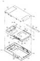
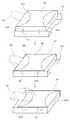
도 2는 본 발명 실시 예에 따른 휴대 가능한 복합형 컴퓨터를 나타낸 분해 사시도.2 is an exploded perspective view showing a portable hybrid computer according to an embodiment of the present invention.
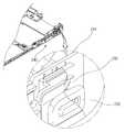
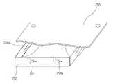
도 3은 본 발명 실시 예에 따른 리어 커버에 다수개의 디바이스를 결합한 상태를 나타낸 사시도.3 is a perspective view showing a state in which a plurality of devices are coupled to the rear cover according to an embodiment of the present invention.
도 4 및 도 5는 본 발명 실시 예에 따른 버튼 어셈블리의 분해 사시도.4 and 5 are exploded perspective views of the button assembly according to an embodiment of the present invention.
도 6은 본 발명 실시 예에 따른 버튼 어셈블리의 체결 전/후 상태를 나타낸 도면.6 is a view showing a state before and after fastening the button assembly according to an embodiment of the present invention.
도 7은 본 발명 실시 예에 따른 전원 스위치의 분해 사시도.7 is an exploded perspective view of a power switch according to an embodiment of the present invention.
도 8은 본 발명 실시 예에 따른 전원 스위치의 결합 상태도.8 is a combined state diagram of a power switch according to an embodiment of the present invention.
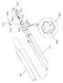
도 9는 본 발명에 따른 스타일러스 홀더의 분해 사시도.9 is an exploded perspective view of the stylus holder according to the present invention.
도 10은 본 발명 실시 예에 따른 스타일러스 홀더의 동작 상태도.10 is an operational state diagram of a stylus holder according to an embodiment of the present invention.
도 11은 본 발명 실시 예에 따른 스타일러스의 수납/인출 상태도.11 is a storage / withdrawal state of the stylus according to an embodiment of the present invention.
도 12 및 도 13은 본 발명 실시 예에 따른 하드디스크드라이브 착탈장치를 나타낸 분해사시도.12 and 13 are exploded perspective view showing a hard disk drive detachment apparatus according to an embodiment of the present invention.
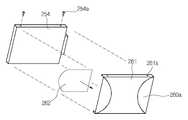
도 14는 본 발명 실시 예에 따른 하드디스크드라이브의 절연 및 분리 구조의 분해 사시도14 is an exploded perspective view of an insulating and separating structure of a hard disk drive according to an exemplary embodiment of the present invention.
도 15 내지 도 17은 본 발명 실시 예에 따른 하드디스크드라이브의 절연 및 분리 구조의 결합 공정을 나타낸 도면.15 to 17 are views illustrating a coupling process of an insulating and separating structure of a hard disk drive according to an exemplary embodiment of the present invention.
도 18은 본 발명 실시 예에 따른 하드디스크드라이브가 브라켓에 슬라이딩 결합 동작 상태를 나타낸 도면.18 is a view showing a sliding coupling operation state on the bracket of the hard disk drive according to an embodiment of the present invention.
도 19는 본 발명 실시 예에 따른 하드디스크드라이브의 결합 상태도.19 is a combined state diagram of a hard disk drive according to an embodiment of the present invention.
도 20은 본 발명 실시 예에 따른 경사각도 조절장치의 동작 상태도.20 is an operational state diagram of the inclination angle adjustment device according to an embodiment of the present invention.
도 21은 본 발명 실시 예에 따른 경사각도 조절장치의 분해 사시도.Figure 21 is an exploded perspective view of the inclination angle adjustment device according to an embodiment of the present invention.
도 22는 본 발명 실시 예에 따른 경사각도 조절장치의 결합 공정을 나타낸 도면.22 is a view showing a coupling process of the tilt angle adjusting device according to an embodiment of the present invention.
도 23은 본 발명 실시 예에 따른 경사각도 조절장치의 동작 상태도.Figure 23 is an operating state diagram of the inclination angle adjustment device according to an embodiment of the present invention.
* 도면의 주요부분에 대한 부호의 설명 *Explanation of symbols on the main parts of the drawings
100...웹 패드110...프런트 커버100 ...
120...강화유리121...양면 테이프120 Tempered
121...LCD 패널126...디지타이저 패널121
170...경사각도조절장치200...스타일러스170 ... Tilt angle adjuster 200 ... Stylus
210...리어커버220...스타일러스 홀더210.Rear
230...전원 스위치240...버튼 어셈블리230
250...HDD 브라켓254...HDD250 ... HDD Bracket 254 ... HDD
265...배터리 수납장치265 battery holder
본 발명은 휴대 가능한 컴퓨터에 관한 것으로, 보다 상세하게는 이종의 패널을 갖는 웹 패드 내부에 메인보드와 더불어, 컴퓨팅 기능 수행을 위해 필요한 장치들이 용이하게 결합될 수 있도록 한 휴대 가능한 복합형 컴퓨터에 관한 것이다.BACKGROUND OF THE INVENTION 1. Field of the Invention The present invention relates to a portable computer. More particularly, the present invention relates to a portable hybrid computer that allows a device necessary for performing computing functions to be easily combined with a main board inside a web pad having heterogeneous panels. will be.
보다 상세하게는, 웹 패드에 복수의 패널 및 시스템 본체를 내장하고, 시스템 구동 제어를 위한 버튼 어셈블리와, HDD 착탈 및 스타일러스 홀더를 실장하는 리어 커버를 구비한 휴대 가능한 복합형 컴퓨터에 관한 것이다.More particularly, the present invention relates to a portable hybrid computer having a plurality of panels and a system main body embedded in a web pad, a button assembly for system driving control, and a rear cover for mounting and removing a HDD and a stylus holder.
시대의 흐름에 맞추어 현재 사용하고 있는 대부분들의 시스템은 작고 가벼우며 휴대하기에 편리한 특징을 가지고 있다. 노트북 개인용 컴퓨터(Note Book Personal Computer), 개인용 디지털 단말기(PDA; Personal Digital Assistance), 스마트 폰(Smart Phone)등이 그것들이다.In line with the times, most systems in use today are small, light and portable. These include note book personal computers, personal digital assistants, and smart phones.
통상 휴대용 컴퓨터인 노트북 컴퓨터나 휴대용 디지털 단말기는 크게 두 가지 형태를 갖는다. 한 형태는 기본 입력장치인 키보드가 설치되어 있는 형태로 키보드를 중심으로 조작이 이루어지며, 펜은 포인팅 디바이스로 보조 기능을 하도록 구성된 키보드 패드 타입이 있으며, 또 다른 형태는 이동 중에 작업이 편리하도록 한 손으로 컴퓨터를 잡고 다른 손으로 펜이나 손만으로 컴퓨터를 조작할 수 있는 터치 패드 타입의 형태를 갖는다.Notebook computers or portable digital terminals, which are typically portable computers, have two types. One type is equipped with a keyboard, which is a basic input device, and the operation is performed around the keyboard, and the pen has a keyboard pad type configured to serve as a pointing device. It has a form of a touch pad that can hold a computer with a hand and operate the computer with only a pen or hand with the other hand.
여기서, 노트북 컴퓨터로 지칭되는 휴대용 컴퓨터는 일반 데스크탑형 컴퓨터에 비해 가볍고 부피가 작으며, 쉽게 휴대할 수 있어 일반 데스크탑형 컴퓨터에서는 얻을 수 없는 많은 편리함을 얻을 수 있다. 또한, 컴퓨터 사용에 있어서 장소의 제약을 거의 받지 않아 컴퓨터의 활용 범위를 한층 확장시키고 있다.Here, a portable computer, referred to as a notebook computer, is lighter and smaller in volume than a general desktop computer, and can be easily carried, thereby providing a lot of conveniences that cannot be obtained in a general desktop computer. In addition, the use of the computer is hardly restricted by the place, and the use range of the computer is further expanded.
도 1은 종래 월릿 PC의 분해 사시도이다.1 is an exploded perspective view of a conventional wallet PC.
도 1을 참조하면, 종래의 월릿 PC(10)의 하드웨어는 프런트 하우징(20), 리어 하우징(30), 프레임(40), 스크린(60), 그리고 보드(70) 등으로 구성된다. 상기 프레임(40), 스크린(60), 그리고 보드(70) 등은, 상기 프런트 하우징(20)과 리어 하우징(30)의 결합에 의해서 형성되는, 내부 공간에 설치된다. 상기 스크린(60)과 보드(70)는 상기프레임(40)에 결합되어, 상기 내부 공간에 설치된다. 상기 스크린(60)과 보드(70)는 상기 프런트 하우징(20) 또는 리어 하우징(30)에 직접 결합되지 않는 구조를 가지고 있다. 이 구조는 외부로부터 상기 하우징들(20,30)에 충격이 가해졌을 때, 그 충격이 상기 스크린(60)과 보드(70)에 직접 전달되지 않도록 한다. 이 구조는 외부의 충격에 의해서 상기 스크린(60)과 보드(70)가 파손되는 것을 방지할 수 있다. 상기 프레임(40)은 상기 프런트 하우징(20) 및 리어 하우징(30)에 안착되는 구조로 형성된다. 이 프레임(40)은 스크류(76)에 의해서 상기 프런트 하우징(20)에 결합된다. 상기 스크류(76)는 상기 프레임(40)에 형성된 고정 리브를 통하여, 상기 프런트 하우징(20)에 형성된, 보스(24)에 결합된다.Referring to FIG. 1, the hardware of a conventional wallet PC 10 includes a
이러한 종래 월릿 PC에서, 상기 프레임(40)은, 오직 하나의 상기 스크류(76)에 의해서, 상기 프런트 하우징(20)에 결합되도록 구성된 것이다. 물론, 상기 프레 임(40)은 상기 리어 하우징(30)에 결합되도록 구성할 수 있으며, 다른 다양한 방법으로 상기 프레임(40)을 상기 프런트 하우징(20) 또는 리어 하우징(30)에 결합시킬 수 있다.In this conventional wallet PC, the
상기 프레임(40)은 서로 반대되는 면인 제 1 면(42)과 제 2 면(44)을 갖고 있다. 상기 제 1 면(42)과 제 2 면(44)은 상기 프레임(40)상에서 임의의 면이 될 수 있다. 상기 제 1 면(42)에는 상기 스크린(60)이 결합되고, 상기 제 2 면(44)에는 상기 보드(70)가 결합된다. 상기 스크린(60)의 표시 화면은 상기 프런트 하우징(20)에 형성된 오프닝(22)을 통하여 외부로 노출된다. 상기 스크린(60)과 보드(70)를 상기 프레임(40)에 결합시키기 위한 구성은 다양한 방법이 사용될 수 있다.The
종래에는 다수 개의 서포팅 리브들(46)을 사용하였다. 상기 서포팅 리브들(46)은 상기 프레임(40)의 측면으로부터 형성된다. 즉, 상기 서포팅 리브들(46)은 상기 제 1 면(42)과 제 2 면(44)의 측면으로부터 형성된다. 이와 같은 구성은 상기 프레임(40)상에 다수 개의 디바이스들을 적층되는 형태로 결합시킬 수 있다는 것을 의미한다. 이 방법은, 이 분야의 종사자들이라면, 용이하게 실현할 수 있을 것이다. 상기 보드(70)는 상기 제 2 면(44)으로부터 일정한 높이를 유지하도록 할 수 있다. 이는 상기 보드(70)의 양면에 전자 회로가 설치되는 경우에 효과적으로 사용될 수 있다. 이 구성도 다양한 방법으로 얻을 수 있다.Conventionally, a plurality of supporting
종래에서는 상기 제 2 면(44) 상에 리브들(48)을 형성하여 상기 보드(70)를 지지하도록 하였다.In the related art, ribs 48 are formed on the
상기 프레임(40)에는 배터리 케이스(52)가 일체로 형성된다. 이 배터리 케이스(52)에는 배터리(도시 않음)가 장착된다. 이 배터리는 상기 리어 하우징(30)에 설치된 도어(32)를 통하여 상기 배터리 케이스(52)에/로부터 장착/탈착된다.The
종래에는, 상기 배터리 케이스(52)가 위치되는, 상기 프런트 하우징(20)의 내면에 스피커를 설치할 수 있도록, 스피커 장착부(28)를 형성하였다. 이 구조는 상기 월릿 PC(10)의 내부 공간을 효율적으로 사용할 수 있도록 하고, 상기 스피커의 조립 또는 분해를 용이하게 할 수 있도록 한다. 상기 스피커는 상기 월릿 PC(10)를 분해하지 않고도, 상기 도어(32)를 통하여 결합 또는 분해할 수 있다. 상기 보드(70)에 배터리 단자들(74)을 설치할 수 있다. 상기 배터리 단자들(74)은 상기 보드(70)를 상기 프레임(40)에 결합시킬 때, 상기 배터리 케이스(52)에 바로 결합시킬 수 있도록 한다. Conventionally, the
상기 보드(70)에는 다양한 기능을 갖는 스위치들(72)이 설치될 수 있다. 예컨대, 상기 월릿 PC(10)는 간단한 조작을 통하여 시스템을 사용할 수 있도록 구현되므로, 다양한 기능 버튼들이 제공된다. 이 스위치들(72)은 상기 프런트 하우징(20)에 설치되는 버튼들(26)에 의해서 작동된다. 상기 버튼들(26)과 스위치들(27)의 구성 및 작동은 생략한다. 상기 월릿 PC(10)는, 소형으로 제작되기 때문에, 작은 공간에 전자 회로를 구성해야 하는 어려움이 있다. 상기 스위치들(72)을 작동시키는 상기 버튼들(26)의 위치는 상기 스위치들(72)에 각각 대응되도록 구성된다. 상기 스위치들(72)은 각각 대응되는 상기 버튼들(26)의 운동 범위에 있어야 한다. 만일, 상기 스위치들(72)이 상기 버튼들(26)의 운동 범위에 들지 않는다면, 상기 스위치들(72)은 작동되지 않을 것이다. 종래에서는 상기 스위치들(72)이 상기 버튼들(26)의 운동 범위에 있지 않을 경우, 미디엄들(mediums)(50)을 사용하였다. 상기 미디엄들(50)은 상기 프레임(40)에 일체로 형성된다. 이 미디엄들(50)은 상기 스위치들(72)과 버튼들(26) 사이에 각각 위치된다. 외부에서 사용자가 소정 기능을 작동시키기 위하여, 상기 버튼들(26) 중에서 어느 하나를 누르면, 그 버튼과 대응되는 미디엄이 동작된다. 그러면, 이 미디엄과 대응되는 스위치가 작동된다. 상기 미디엄들(50)에 의해서, 스위치들(72)이 버튼들(26)의 운동 범위에서 벗어나는 위치에 설치되어도, 상기 스위치들(72)의 동작이 정상적으로 수행된다.The
상기 월릿 PC(10)는 스타일러스(stylus)(80)로 스크린(60)상에 데이터를 입력하는 방식을 사용할 수 있다. 상기 스타일러스(80)는 펜(pen) 또는 펜 첨필(pen stylus) 등으로 불리기도 한다. 스타일러스 입력 방식에는 다양한 형태의 기술이 사용될 수 있다. 예컨대, 스타일러스 입력 방식에서 컨덕티브 스타일러스(conductive stylus)를 사용하는 기술이 있다. 상기 컨덕티브 스타일러스는 코드(cord)에 의해서 월릿 PC에 연결된다. 상기 코드는, 스크린 상의 쓰기 기능(write function)이 가능하도록, 상기 스타일러스와 월릿 PC를 전기적으로 연결하는 내부 컨덕터(conductor)를 가지고 있다. 본 실시예의 월릿 PC(10)는 코드가 필요 없는 스크린 쓰기 기술(screen write technology)을 사용한다. 이와 같은 기술에 사용되는 스크린은 터치 스크린(touch screen)으로 불리기도 한다. 또, 종래의 월릿 PC(10)는 상기 스타일러스(80)를 월릿 PC(10)의 내부에 장착할 수 있도록 한다. 상기 스타일러스(80)는 상기 프레임(40)에 형성된 서포터(54)에 장착된 다. 상기 서포터(54)는 다양한 형태로 구성할 수 있다. 상기 서포터(54)는 상기 스타일러스(80)의 외주면과 동일한 형상의 내부면을 갖도록 형성된다. 상기 스타일러스(80)는 상기 서포터(54)에 장착되었을 때, 훅(hook)(56)에 의해서 고정되어 임의로 상기 서포터(54)로부터 이탈되지 않도록 한다. 상기 훅(56)은 상기 스타일러스(80)의 외주면상에 형성된 그루브(82)에 결합되어, 상기 스타일러스(80)가 상기 서포터(54)로부터 이탈하지 않도록 한다. 상기 훅(56)은 상기 스타일러스(80)가 상기 서포터(54)에/으로부터 장착/착탈되는 방향으로 형성된다. 이 훅(56)은 자유단의 형태로 형성된다. 이 자유단의 구조에 의해서, 상기 훅(56)은 상기 서포터(54)의 내부면상에서 탄성적으로 운동할 수 있다. 또, 이 훅(56)은 상기 스타일러스(80)의 외주면과 접촉되는 방향으로 돌출되도록 형성된다.The
상기 프런트 하우징(20)에는 제 1 노치(29)가 형성되고, 상기 리어 하우징(30)에는 제 2 노치(34)가 형성된다. 이 제 1노치(29) 및 제 2 노치(34)는, 상기 프런트 하우징(20)과 리어 하우징(30)이 결합되었을 때, 오프닝을 형성한다. 이 제 1 노치(29) 및 제 2 노치(34)에 의한 오프닝을 통하여, 상기 스타일러스(80)는 상기 서포터(54)에/로부터 장착/착탈된다.A
월릿 PC(10)의 스크린(60)과 보드(70)는 프레임(40)에 결합되어 상기 월릿 PC(10)의 내부에 위치된다. 상기 스크린(60)과 보드(70)는 상기 월릿 PC(10)의 프런트 하우징(20) 및 리어 하우징(30)과 결합 관계를 갖지 않는다. 상기 프레임(40)은 상기 프런트 하우징(20)에 하나의 스크류(76)에 의해서 결합되고, 상기 스크린(60) 및 보드(70)는 상기 프레임(40)에 의해서 지지된다. 상기 스크린(60)이 상기 프런트 하우징(20)에 접촉되는 부분에는 탄성 성질을 갖는 절연체(도시 안됨)를 사용할 수 있다. 또한, 상기 프레임(40)에는 배터리 케이스(52)를 일체로 형성할 수 있다. 이 배터리 케이스(52)에 설치되는 배터리 단자들(74)(도 2참조)은 상기 보드(70)에 설치할 수 있다. 상기 배터리 단자들(74)은 상기 보드(70)를 상기 프레임(40)에 장착할 때, 바로 결합된다.The
그러나, 종래에는 일측 케이스(top 또는 bottom case)에서 시작하여 스크린, 보드 등이 순차적으로 결합되고 나머지 케이스가 체결되는 공정이다. 이러한 공정은 제조 공정에서 모든 부품을 한 번에 결합해야 하고, 보드 또는 스크린 부분만을 수리할 때에도 모두 분해해야 하는 문제가 있다.However, in the related art, a screen, a board, and the like are sequentially coupled to each other, starting from one top or bottom case, and the remaining cases are fastened. This process has a problem in that all parts must be joined at once in the manufacturing process, and all of them must be disassembled when only the board or screen part is repaired.
또한 하부 케이스측의 충돌에 대비한 서포팅 리브가 존재하나 스크린에 직접적으로 가해지는 충격에는 약하다. 즉, 스크린이 월릿 PC의 오프닝 부분을 통해 개방되어 있기 때문에 외부로부터 이물질 유입 가능성이 크고, 또 직접적인 충격으로 인해 파손의 문제가 발생하게 된다.
In addition, there is a supporting rib in case of a collision on the lower case side, but it is weak in the impact applied directly to the screen. That is, since the screen is opened through the opening part of the wallet PC, foreign matter may be introduced from the outside, and a problem of damage may occur due to a direct impact.
상기와 같은 문제점을 해소하기 위하여 안출된 본 발명은, 복수의 디스플레이 패널 및 시스템 본체가 내부에 설치시키고 웹 패드 기능과 노트북 기능을 함께 가능하도록 한 휴대 가능한 복합형 컴퓨터를 제공함에 그 목적이 있다.The present invention has been made in order to solve the above problems, it is an object of the present invention to provide a portable hybrid computer that has a plurality of display panel and the system main body installed therein and enable both the web pad function and the notebook function.
본 발명의 다른 목적은 프런트 커버에 패널을 실장하고, 리어 커버에 각 종 기능 제어를 위한 버튼 어셈블리, 전원 스위치 및 하드디스크드라이브 착탈장치, 스타일러스 홀더, 경사각도 조절장치를 일체로 갖는 휴대 가능한 복합형 컴퓨터를 제공함에 그 목적이 있다.Another object of the present invention is to mount a panel on the front cover, a portable assembly having a button assembly for controlling various functions on the rear cover, a power switch and a hard disk drive detachable device, a stylus holder, tilt angle adjustment device integrally The purpose is to provide a computer.
상세하게 버튼 어셈블리는 리어 커버와 훅크 및 훅크 걸림홈 방식으로 체결할 수 있도록 함에 있다.In detail, the button assembly can be fastened to the rear cover and the hook and hook hook groove method.
상세하게 전원 스위치는 전원 스위치를 소정 힘으로 눌러 전원 온시킴과 동시에 텐션 작용에 의해 원 위치를 복원되도록 함에 있다.In detail, the power switch is to turn on the power by pressing the power switch with a predetermined force and to restore the original position by the tension action.
상세하게 하드디스크드라이브 착탈장치는 하드디스크를 슬라이딩 방식을 결합함과 동시에, 직접 커넥터 접속이 가능케 함에 있다.In detail, the hard disk drive detachment device combines a sliding method of the hard disk and at the same time enables direct connector connection.
상세하게 스타일러스 홀더는 스타일러스를 푸쉬-푸쉬 방식으로 수납/인출되도록 함에 있다.Specifically, the stylus holder is intended to receive / draw the stylus in a push-push manner.
상게하게 경사각도 조절장치는 경사조절레버에 소정의 작동감을 전달해 주어 일정 경사 각도 전/후에서 꺽이고 접혀질 수 있도록 함에 있다.The inclination-angle adjusting device is provided so as to transmit a predetermined feeling of operation to the inclination control lever so that it can be folded and folded before and after a predetermined inclination angle.
본 발명은 프런트 커버와 리어 커버에 실장되는 디바이스들을 분리시켜 결합시켜 줌으로써, 제품의 유지 및 보수를 편리하게 할 수 있도록 한 휴대 가능한 복합형 컴퓨터를 제공함에 그 목적이 있다.
It is an object of the present invention to provide a portable hybrid computer which can separate and couple devices mounted on a front cover and a rear cover to facilitate maintenance and repair of a product.
상기한 목적 달성을 위한 본 발명에 따른 휴대 가능한 복합형 컴퓨터는,Portable computer according to the present invention for achieving the above object,
전면에 강화 유리를 부착시키고 상기 강화 유리로부터 소정 이격된 내부에 이종의 디스플레이 패널을 실장하는 프런트 커버와;A front cover attaching tempered glass to a front surface and mounting heterogeneous display panels in a predetermined spaced distance from the tempered glass;
상기 프런트 커버와 대향하여 상기 패널 구동을 위한 메인보드를 내부 일측에 실장하는 리어 커버와;A rear cover mounted on an inner side of the main board for driving the panel to face the front cover;
상기 리어 커버의 우측면으로 각 종 기능 제어를 위한 버튼 어셈블리 및 전원 온/오프를 위한 전원 스위치와, 스타일러스를 푸쉬-푸쉬 방식으로 수납/인출하기 위한 스타일러스 홀더와, 리어 커버의 내부 타측에 HDD의 착/탈을 위한 HDD 착탈장치를 일체로 실장하는 것을 특징으로 한다.On the right side of the rear cover, a button assembly for controlling various functions, a power switch for power on / off, a stylus holder for storing / drawing the stylus in a push-push manner, and attaching an HDD to the other side of the rear cover It is characterized in that the HDD detachment device for mounting / detaching integrally.
바람직하게, 상기 버튼 어셈블리는, 상기 리어 커버의 일측에 다수개가 해당 기능 수행을 위해 설치된 누름 조작 수단 및 세로 방향으로 회전 조작을 위한 회전 조작 수단을 포함하는 버튼 커버와; 상기 버튼 커버와 상기 버튼 커버의 각 조작수단과 대응하는 스위치 접점을 갖는 버튼 기판을 훅크 및 훅크 걸림 홈으로 결합하기 위한 제 1체결수단과; 상기 버튼 커버의 하부 및 상기 버튼 커버의 하부를 지지하기 위해 웹 패드 커버에 서로 대응하여 돌출 형성된 훅크 및 훅크 걸림 돌기를 갖는 제 2체결 수단을 포함하는 것을 특징으로 한다.Preferably, the button assembly, a button cover comprising a plurality of push operation means installed on one side of the rear cover for performing the corresponding function and a rotation operation means for rotating operation in the vertical direction; First fastening means for engaging the button substrate having a switch contact corresponding to the button cover and each operation means of the button cover with a hook and a hook engaging groove; And a second fastening means having hooks and hook catching protrusions protruding to correspond to each other on the web pad cover to support the lower part of the button cover and the lower part of the button cover.
바람직하게, 상기 전원 스위치는 내향 돌출된 텐션 돌기 홈 및 이에 경사지게 연장된 텐션 바를 일체로 갖는 전원 스위치와; 상기 전원 스위치와 대응하는 곡면 조립체에 결합되어 상기 텐션 돌기 홈에 체결되어 탄성력에 의한 압입/복원되는 버튼 기판의 텐션 돌기를 포함하는 것을 특징으로 한다.Preferably, the power switch includes: a power switch integrally having an inwardly projecting tension protrusion groove and an inclined tension bar; And a tension protrusion of the button substrate coupled to the curved assembly corresponding to the power switch and fastened to the tension protrusion groove to be pressed / restored by an elastic force.
바람직하게, 상기 스타일러스 홀더는 디지타이저 패널에 대응하여 입력하기 위한 스타일러스와; 커버 내부에 스타일러스를 수납시키기 위해, 스타일러스를 통과시켜 수납되는 펜 통과; 사용자의 수납/인출 동작에 따른 스타일러스이 연동할 때 상기 스타일러스의 수납 및 인출을 위해 상기 스타일러스를 푸쉬-푸쉬 방식으로 전/후 이동시켜 주는 푸쉬-푸쉬 버튼을 포함하는 것을 특징으로 한다.Preferably, the stylus holder comprises a stylus for input corresponding to the digitizer panel; A pen passage through which the stylus is received to receive the stylus inside the cover; And a push-push button for moving the stylus back and forth in a push-push manner for storing and withdrawing the stylus when the stylus is interlocked according to a user's storing / drawing operation.
바람직하게, 상기 푸쉬-푸쉬 버튼은 스타일러스가 수납될 때 펜 팁을 압입시켜 고정하기 위한 펜 팁 압입부와; 스타일러스에 전달되는 외부 힘에 의해 상기 펜 팁 압입부를 탄성력으로 압입/복원 동작으로 전/후 이동시키는 커버에 고정된 푸쉬 버튼부를 포함하는 것을 특징으로 한다.Preferably, the push-push button comprises: a pen tip push-in for pressing and fixing the pen tip when the stylus is received; It characterized in that it comprises a push button fixed to the cover for moving the pen tip indentation portion by the external force transmitted to the stylus to the front / rear in the indentation / restoration operation with elastic force.
바람직하게, 상기 펜 팁 압입부의 내부 전면에서 수납되는 스타일러스의 팁 외주변을 압입하는 압입 바와; 상기 펜 팁 압입부 및 푸쉬 버튼부의 배면 및 측면에 서로 대응하여 형성되고 상기 펜 팁 압입부의 전/후 회동을 가이드하기 위한 가이드 돌기 및 홈과; 상기 펜 팁 압입부 및 푸쉬 버튼부 사이에서 상기 펜 팁 압입부의 전/후 회동을 위해 소정의 탄성력에 의한 압입/복원력을 전달하는 탄성 수단과; 상기 펜 팁 압입부의 전/후 방향 회동이 전달되는 외부 힘에 연동하도록 상기 펜 팁 압입부 및 푸쉬 버튼부에 대응하여 형성되고, 펜 팁 압입부의 푸쉬 동작시 후 방향 위치에서 체결되어 정지시키고, 펜 팁 압입부의 새로운 푸쉬 동작시 상기 체결 상태가 분리시켜 펜 팁 압입부를 전 방향으로 밀쳐주는 멈춤돌기 및 멈춤홈을 포함하는 것을 특징으로 한다.Preferably, the indentation bar for press-in the outer periphery of the tip of the stylus accommodated in the inner front of the pen tip indentation; Guide protrusions and grooves formed to correspond to the back and side surfaces of the pen tip pressing portion and the push button portion, and for guiding forward / backward rotation of the pen tip pressing portion; Elastic means for transmitting a pressing / restoring force by a predetermined elastic force for the front / rear rotation of the pen tip pressing portion between the pen tip pressing portion and the push button portion; The pen tip indentation part is formed to correspond to the pen tip indentation part and the push button part so as to cooperate with the external force transmitted to the front / rear rotation. When the new push operation of the tip push-in portion, the fastening state is characterized in that it comprises a stop projection and the stop groove for pushing the pen tip indentation in all directions.
바람직하게, 상기 HDD 착탈장치는 HDD(HDD)를 수납하고 리어 커버에 결합되는 HDD 브라켓과; 접속을 위한 커넥터를 갖고 HDD 브라켓에 착/탈되는 HDD와; 상기 HDD 브라켓과 HDD 양측에 복수개를 서로 대향하게 형성된 착탈돌기 가이드 홈 및 착탈돌기를 갖되, 상기 착탈돌기 가이드 홈을 L자 형상으로 형성시켜 상기 착탈돌 기 가이드 홈으로 착탈돌기가 슬라이딩 결합될 수 있도록 한 것을 특징으로 한다.Preferably, the HDD detachable device includes an HDD bracket for accommodating the HDD (HDD) and coupled to the rear cover; An HDD attached / removed to / from the HDD bracket having a connector for connection; A plurality of detachable protrusion guide grooves and detachable protrusions are formed on both sides of the HDD bracket and the HDD so as to face each other, and the detachable protrusion guide grooves are formed in an L shape so that the detachable protrusions can be slid to the detachable protrusion guide grooves. It is characterized by one.
바람직하게, HDD용 커넥터 측으로 슬라이딩 될 수 있도록 양 측면에 가이드 홈을 가공한 HDD 브라켓과; 상기 HDD 브라켓에 착탈되고, 외부의 힘에 의해 상기 착탈돌기 가이드 홈을 따라 상기 메인 보드에 구비된 하드디스크 드라이브용 커넥터와 접속되도록 이동하는 착탈 돌기를 갖는 하드디스크 드라이브와; 상기 HDD 브라켓의 결합된 하드 디스크 드라이브의 절연을 위한 부착되는 절연 필름과; 상기 절연 필름이 내측에 부착되고 좌/우측면이 하드 디스크 드라이드의 가이드 돌기에 체결되어, 하드 디스크 드라이드의 배향면에 결합되는 노출된 필름 고정판을 포함하는 것을 특징으로 한다.Preferably, the HDD bracket having a guide groove on both sides so as to slide toward the connector for the HDD; A hard disk drive detachably attached to the HDD bracket and having a detachable protrusion moved by an external force to be connected to a connector for a hard disk drive provided on the main board along the detachable protrusion guide groove; An insulating film attached for insulation of the hard disk drive coupled to the HDD bracket; The insulating film is attached to the inside and the left / right side is fastened to the guide projection of the hard disk drive, characterized in that it comprises an exposed film fixing plate coupled to the orientation surface of the hard disk drive.
바람직하게, 상기 HDD 착탈장치는 하드 디스크 드라이브의 분리를 위해 상기 필름 고정판에 분리 손잡이를 갖는 것을 특징으로 한다.Preferably, the HDD detachment device is characterized in that the separation handle on the film fixing plate for the separation of the hard disk drive.
바람직하게, 상기 리어 커버의 상부 저면 양측에 휴대용 컴퓨터의 사용 상태에 따라 지면에 대해 경사 각도를 조절시켜 주기 위한 경사각도 조절 장치를 더 포함하고, 상기 경사각도 조절장치는, 헤드 부위에서 전/후 회동을 지지하는 회전축 삽입홈 및 회전 정도에 따라 작동감을 주기 위한 탄성편 걸림돌기를 갖고 리어 커버에 결합되며 일정 각도 전/후로 회동하는 경사각도 조절 레버와; 상기 경사각도 조절 레버의 회동을 가이드하기 위한 회전축과; 상기 경사각도 조절 레버의 회동을 일정 각도에서 전/후 회동시켜 주기 위한 판 스프링과; 상기 경사 각도 조절 레버의 일정 각도 이상의 회동을 제한하기 위한 스톱퍼를 포함하는 것을 특징으로 한다.Preferably, the inclination angle adjustment device for adjusting the inclination angle with respect to the ground in accordance with the use state of the portable computer on both sides of the upper bottom of the rear cover, the inclination angle adjustment device, before / after the head portion An inclination angle adjustment lever which is coupled to the rear cover and has an elastic piece engaging protrusion for giving a feeling of operation according to the degree of rotation and a rotation shaft insertion groove for supporting rotation; A rotating shaft for guiding the rotation of the tilt angle adjusting lever; A leaf spring for rotating the tilt angle adjusting lever forward and backward at a predetermined angle; It characterized in that it comprises a stopper for limiting the rotation of the tilt angle adjustment lever more than a predetermined angle.
이하 첨부된 도면을 참조하여 설명하면 다음과 같다.Hereinafter, with reference to the accompanying drawings as follows.
도 2는 본 발명 실시 예에 따른 휴대 가능한 복합형 컴퓨터의 분해 사시도이고, 도 3은 본 발명에 따른 리어커버의 결합 상태도이며, 도 4내지 도 8은 버튼 어셈블리 및 전원 스위치의 결합 구조를 나타낸 도면이고, 도 9내지 도 11은 스타일러스 홀더를 나타낸 도면이며, 도 12 내지 도 19는 하드디스크드라이브의 착탈 장치를 나타낸 도면이고, 도 20 내지 도 23은 경사각도 조절장치를 나타낸 도면이다.2 is an exploded perspective view of a portable hybrid computer according to an exemplary embodiment of the present invention, FIG. 3 is a diagram illustrating a coupling state of a rear cover according to the present invention, and FIGS. 4 to 8 are views illustrating a coupling structure of a button assembly and a power switch. 9 to 11 are views showing a stylus holder, FIGS. 12 to 19 are views showing a detachable device of a hard disk drive, and FIGS. 20 to 23 are views showing an inclination angle adjusting device.
도 2를 참조하면, 프런트 커버(110) 상부에 양면 테이프로 부착된 강화 유리(120)와, 프런트 커버 내부에 적층되어 결합된 LCD 패널(123) 및 디지타이저 패널(126)과, LCD 패널(123)의 가장자리와 강화 유리(120) 사이에 밀착되어 부착되는 부직포 개스킷(125)과, 리어 커버(210) 내부 일측에 메인 보드(180), 일측면으로 버튼 어셈블리(240), 전원 스위치(230) 및 스타일러스 홀더(220), 내부 타측에 하드디스크드라이브를 수납하는 HDD 브라켓(250), 배터리 브라켓(265)을 일체로 갖는 구성이다.Referring to FIG. 2, the tempered
상기와 같은 본 발명에 따른 휴대 가능한 복합형 컴퓨터에 대하여 첨부된 도면을 참조하여 설명하면 다음과 같다.Referring to the accompanying drawings, a portable hybrid computer according to the present invention as described above is as follows.
도 2를 참조하여 휴대 가능한 복합형 컴퓨터의 이종의 디스플레이 패널 결합장치에 대하여 상세하게 설명하면 다음과 같다. 설명의 편의를 위해 세로 방향이 가로 방향 보다 긴 포트레이트 방향을 디폴트 모드로 하여 설명하기로 한다.Referring to Figure 2 will be described in detail with respect to the heterogeneous display panel coupling device of a portable hybrid computer. For convenience of description, a portrait direction having a longer vertical direction than a horizontal direction will be described as a default mode.
웹 패드(100)는 크게 프런트 커버(Front cover)(110)와 리어 커버(rear cover)(210)로 구성되고, 프런트 커버(110)에는 서로 다른 종류의 디스플레이 패널(122,126)과 상기 디스플레이 패널을 보호 및 지지하기 위한 부재 등을 포함하며, 리어 커버(210)에는 시스템 동작을 위한 메인보드(Main board, 180), 하드디스크 드라이브(이하 HDD라 약칭함) 및 배터리(Battery), 스타일러스 홀더(220) 등이 결합된다.The
여기서, 프런트 커버(110)는 플라스틱 재질이고, 리어 커버(210)는 마그네슘 재질로 하여 내부에서 발생되는 열의 방열 및 경량화시켜 준다.Here, the
먼저, 프런트 커버(110)는 내부가 개방된 구조를 갖고 전면 외측 둘레면으로 강화 유리 삽입홈(111a)이 형성되어, 전면으로 강화 유리(120)를 부착시키고, 내부에 LCD 패널(121) 및 디지타이저 패널(122)이 결합된다.First, the
리어 커버(210)에는 시스템 구동을 위한 시스템 본체(HDD, 메인보드 등) 및 배터리 브라켓(265) 및 HDD 브라켓(250), 스타일러스(200)가 수납되는 스타일러스 홀더(220), 그리고 각 종 기능 제어를 위한 버튼(242,243) 및 전원스위치(230)가 결합된다.The
여기서, 상기 프런트 커버(110)에 실장되는 전면 강화 유리(120)와 LCD 패널(121)은 먼지 등의 이물질이 유입되면 제품에 악 영향을 미치므로, 내부에 먼지 등의 이물질이 유입되는 것을 방지하기 위해, 상기 크리닝 룸(cleaning room)에서 강화 유리(120)와 LCD 패널(121)의 결합 공정을 수행한다.Here, the front tempered
프런트 커버의 구성요소 결합 구조를 설명하면 다음과 같다.Referring to the component coupling structure of the front cover as follows.
도 2에 도시된 바와 같이, 강화 유리(120)는 소정의 강도를 갖는 투명한 재질로 이루어지며, 프런트 커버(110)의 전면 강화 유리 삽입홈(111a)에 부착된다. 실시 예로서, 부착부재는 양면 테이프 등이 해당된다. 상기 양면 테이프(120b)는 가로 대비 세로의 폭이 다른 띠 모양을 이루며, 강화 유리(120)의 저면 외측 테두리 면에 먼저 부착되고, 양면 테이프(121)가 부착된 강화 유리(120)는 프런트 커버(110)의 전면 외측 둘레면에 형성된 강화 유리 삽입홈(111a)에 부착되어 고정된다. 이로써, 강화 유리(120)는 프런트 커버(110)에 별도의 나사 체결 없이 밀착 고정하게 된다.As shown in FIG. 2, the tempered
그리고, LCD 패널을 지지하기 위한 외주변 프레임(123)의 좌/우측으로는 고정 프레임(124)을 나사(101)로 체결해 준다. 즉, 외주변 프레임(123)의 좌/우측 모서리에 형성된 나사구멍(102)과 고정 프레임(124)의 나사구멍(102)을 대향시킨 후 LCD 패널(122)의 전면에서 후면 방향으로 나사(101)를 이용하여 체결하여 준다.The fixing
이러한 LCD 패널(122)과 외주변 프레임(123) 사이에 띠 모양의 부직포 개스킷(gasket)(125)을 부착시키고, 프런트 커버(110)에 밀착시키면 LCD 패널(121)에 부착된 부직포 개스킷(125)은 상기 강화 유리(120)의 테두리에 부착된 양면 테이프(121)에 부착된다. 그리고, 고정 프레임(124)의 상/하에 가공된 나사구멍(102)을 통해서 나사(101)로 프런트 커버(110)의 보스(111b)에 체결하여 줌으로써, LCD 패널(122)을 프런트 커버(110)에 고정시켜 준다.A band-shaped
그리고 양면 테이프(121)는 외부 영역으로는 강화 유리와 강화 유리 삽입홈(111a)을 일체화시켜 고정하고, 내부 영역으로는 강화 유리(120)와 부직포 개스킷(125)이 부착된다.The double-
이와 같이, LCD 패널(110)은 외부에 소정 두께를 갖는 부직포 개스킷(125), 양면 테이프(121), 강화 유리(120)에 의해 전면이 밀봉된 상태에 놓이기 때문에 외부로부터의 이물질 유입을 차단할 수 있다.As such, the
그리고, 디지타이저 패널(126)을 LCD 패널의 배면으로 적층시켜 주기 위해 프레임(123, 124)에 형성된 나사구멍(102)을 통해서 나사(101)로 체결하여 줌으로써, LCD 패널(122)과 디지타이저 패널(126)이 적층되어 결합된다. 이러한 LCD 체결 구조는 LCD 패널(122)을 일차로 내부에서 프레임으로 지지한 후, 내부 보스에 체결함으로써, 나사 체결 구조가 프런트 커버(110)의 전면으로 노출되지 않는다.In addition, the
또한, 프런트 커버(110)의 전면으로 강화 유리(120)를 결합하기 때문에, LCD 패널(110)에 외부 충격을 분산시켜 전달하지 않을 뿐만 아니라, 양면 테이프(121)가 외부 충격에 대해 소정의 완충 작용을 하여 패널에 전달되는 충격을 최소화한다. 또한 LCD 패널(110)의 전면 및 측면 부위에서 LCD 패널(110)의 표시 부분을 밀봉해 줌으로써, 이물질의 유입을 차단하여 제품의 신뢰성을 향상시켜 줄 수 있다.In addition, since the tempered
그리고, 프런트 커버(110)에 결합되는 이종의 디스플레이 패널(122,126)의 특정 부분이 쳐지는 것을 지지하기 위해, 프런트 커버(110)의 내부에 패널이 결합되면 상기 디스플레이 패널의 배면 중심부를 경유하는 "L" 자 형태로 지지해 주는 지지부재(미도시)를 프런트 커버(110)에 나사(101)로 체결해 준다. 이로써, 패널 체결 작업은 완료된다.In addition, when the panel is coupled to the inside of the
그리고, LCD 패널(121)의 구동을 위한 인버터 회로기판과 인버터 케이블을 접속시키고, LCD 인버터 회로기판 및 디지타이저 제어기판을 디지타이저 패널(122) 배면에 위치 및 결합시킨다. 또한 LCD 패널(121) 및 디지타이저 패널(122)에는 상 부 내측에 인버터를 설치하여 적정 전압을 각각 공급해 주며, 인버터에 전기적으로 보조 배터리를 연결하여, 주 배터리의 교체시에나 배터리의 용량 부족시 최소한의 작업을 위해 LCD 패널(121)에 전원을 공급해 줄 수 있다.The inverter circuit board and the inverter cable for driving the
이러한 이종의 디스플레이 패널(121,122)을 내장한 프런트 커버(110)는 리어 커버(210)와 결합되는데, 상기 리어 커버(210)에는 메인보드(180), 상기 메인보드와 전기적으로 접속된 HDD 및 배터리가 함께 결합된다. 상기 HDD는 HDD 브라켓(250) 및 배터리는 배터리 브라켓(265)에 각각 결합된다.The
또한 스타일러스(200)를 수납/인출하기 위한 스타일러스 홀더(220)를 실장하며, 일측으로 각 종 기능 제어를 위한 버튼 및 스위치를 포함하는 버튼 어셈블리(240)를 결합시켜 준다.In addition, the
리어 커버(210)에 장착된 메인보드(180)의 하단에는 CD-ROM 드라이브, 및 플로피 디스크 드라이브 등과 인터페이스하기 위한 디스크 드라이브 소켓이 전기적으로 접속되며, 상기 디스크 드라이브 소켓을 사용하지 않을 경우 이물질의 유입을 방지하기 위해 드라이브 커넥터를 결합할 때 열리고 드라이브 커넥터를 분리시킬 때 닫히는 소켓 보호레버를 포함한다.At the bottom of the
메인보드(180)에는 상단 우측으로 PCMCIA 카드 수납부(183)와 USB 포트, 그 중심부에 시리얼 통신 포트, 랜 포트를 포함하는 통신 포트(184)가 전기적으로 접속되어 있으며, 우측으로 DC 입력 잭 및 적외선 통신을 위한 적외선 통신 포트(IrDA: Infrared Data Association)가 연결된다. 그리고 통신 포트를 보호하기 위한 포트 커버가 결합된다.The
프런트 커버(110)와 대향 결합되는 리어 커버(210)에 실장되는 하드디스크 드라이브, 스타일러스, 버튼 어셈블리의 결합 구조를 기술하면 다음과 같다.A coupling structure of a hard disk drive, a stylus, and a button assembly mounted on the
한편, 리어 커버(210)의 상부 우측에는 버튼 어셈블리(240) 및 스타일러스 홀더(220)가 결합되고, 하부 일측에는 HDD 착탈장치, 저면 상단부에는 경사각도 조절장치가 결합되는데, 이러한 결합 구조에 대하여 설명하면 다음과 같다.Meanwhile, the
먼저, 도 4 내지 도 7을 참조하여 버튼 어셈블리의 결합 구조에 대하여 설명하기로 한다.First, the coupling structure of the button assembly will be described with reference to FIGS. 4 to 7.
버튼 어셈블리(240)는 리어 커버(210)의 상부 우측에 결합되고, 버튼 어셈블리(210)의 내측으로 스타일러스(200)를 수납하기 위해 스타일러스 홀더(220)가 결합된다.The
버튼 어셈블리(240)는 우측 상단부에 다수개의 기능 버튼이 결합된다. 이러한 기능 버튼은 전원 스위치, 퀵 버튼, 탭(Tap) 버튼, Esc 버튼, 개인정보 관리 버튼(242)을 포함하는 누름 조작수단과 조그 스위치(243) 등으로 구성된 회전 조작수단이다. 상기 조그 스위치는 중심을 기준으로 상/하 방향으로 이동하여, OSD 조정을 위해 엔터 및 상/하 방향에 대응하는 업/다운 기능으로 레벨 조정 및 메뉴 이동을 수행한다. 또한, 기능 버튼 중의 하나인 개인정보 관리버튼은 전원 오프시 또는 다른 프로그램 실행시에, 팝업 메뉴로 동작하여, 팝업 메뉴 상에서의 정보를 화면상에 제공해 줄 수 있도록 해 준다. 이러한 팝업 메뉴 정보로는 사용자의 개인 정보 또는 스케쥴 정보 등을 포함한다.The
도 3에 도시된 바와 같이, 리어 커버(210)의 우측 상단 제 4곡면 조립체(144)에는 전원 스위치(230)가 결합되고, 상단면으로 스타일러스 홀더(220)에 수납되는 스타일러스(200)가 관통할 수 있는 펜 관통구멍(220a)이 형성되어 있다.As shown in FIG. 3, the
버튼 어셈블리(240)는 우측 상단부에 다수개의 기능 버튼을 갖는 버튼 커버(241)와, 다수개의 접점 스위치를 갖는 버튼 기판(244)으로 구성되며, 상기 버튼 커버(241)에는 전원 버튼, 퀵 버튼, 탭(Tap) 버튼, Esc 버튼, 개인정보 관리 버튼를 포함하는 버튼(242), 조그 다이얼(243) 등의 기능 버튼이 형성되며, 각 버튼은 결합 구조에 의해 소정의 탄성력을 제공받는다.The
또한 버튼 커버(241)는 각 종 기능 버튼(242)이 일체로 형성되며, 조그 다이얼(243)은 별도로 결합된다. 버튼 커버(241)에는 상기 버튼 기판(244)과 결합되기 위한 기판 고정 훅크(245), 하단부에 내향 돌출된 제 1훅크 걸림홈(246) 및 제 2훅크 걸림턱(247)이 형성되며, 일측에 안착 돌기 홈(248)이 형성된다. 이에 대향하는 버튼 기판(244)에는 훅크 홈(244a)이 형성되어 있으며, 또 상기 버튼 어셈블리(240)가 결합되는 리어 커버(210)에는 지그재그로 형성된 제 1 및 제 2훅크(246a,246b), 그리고 좌/우에는 안착홈(248)과 결합되는 안착 돌기(248a)가 형성되어 있다.In addition, the
그러면, 버튼 커버(241)와 버튼 기판(244)의 결합시에는, 버튼 커버(241)에 버튼 기판(244)을 밀착시키면 상기 버튼 커버(241)에 형성된 기판 고정 훅크(245)가 버튼 기판(242)의 훅크 홈(245a)에 걸려 결합되며, 버튼 커버(241)의 각 기능 버튼이 버튼 기판(242)의 접점 스위치와 대응하며, 조그 다이얼(243)을 조그 접점 스위치와 대응하도록 결합하게 된다.Then, when the
이러한 버튼 어셈블리(240)를 도 5에 도시된 바와 같이 리어 커버(210)에 위치시킨 후, 상기 버튼 커버(241)를 도 6과 같이 일정 경사(θ=30도)지게 하여 리어 커버(210)의 결합부분에 위치시킨다. 이때 버튼 커버(241)의 하단 중심부에 내향 돌출된 제 1훅크 걸림홈(246)을 리어 커버(210)의 중심부에 내향 돌출된 제 1훅크(246a)에 끼운 후, 상기 버튼 커버(241)를 세우면 상기 제 1훅크(246a)의 좌/우측에서 외향 돌출된 제 2훅크(247a)에 상기 버튼 커버(241)의 제 2훅크 걸림턱(247)이 걸려진다. 즉, 제 1훅크 걸림홈(246) 및 제 2훅크 걸림턱(247)은 버튼 커버의 하단에서 동일 선상으로 소정 이격되어 내향되게 돌출되고, 이에 대응하는 제 1 훅크(246a)와 제 2훅크(247a)가 지그재그로 형성되어 있으므로, 결합시 서로 간에 지지하는 힘이 발생된다.After the
여기서, 제 1훅크(246a) 및 제 2훅크(247a)는 리어 커버(210)를 몰리브덴으로 사출 성형하기 때문에, 많은 나사의 체결 작업이 없고 간단한 금형으로 체결 수단으로서 기능을 수행하게 된다.Here, since the
이때, 버튼 커버(241)의 일측에 형성된 안착홈(248)에는 리어커버(210)로부터 상향 돌출된 안착돌기(248a)가 끼워지고, 나사를 나사 관통구멍에 체결하여 줌으로써, 상기 훅크 방식의 결합 부분과 함께 버튼 어셈블리를 고정시켜 준다.At this time, the mounting
또한, 전원 스위치(230)에는 내향 돌출된 텐션 돌기 홈(233) 및 그 홈(233)의 양측에 형성된 훅크(234), 그리고 상기 텐션 돌기 홈(233)으로부터 좌측에 연장되어 경사지게 형성된 텐션 바(235)를 포함한다.In addition, the
그리고, 도 7에 도시된 바와 같이, 곡면 조립체(144)의 전원 스위치 가이드 홈(231)을 통해 전원 스위치(233)를 끼워 결합하면, 상기 전원 스위치(233)의 양측면에 형성된 훅크(234)가 전원 스위치 가이드 홈(231)에 끼워져 걸리고, 전원 스위치(233)에 내향 돌출된 텐션 돌기 홈(233)이 버튼 기판(244)의 텐션 돌기(236) 사이로 끼워져 전원 스위치(233)의 결합이 완료된다. 여기서, 도 4에 도시된 바와 같이 텐션 돌기(236)는 일측에 내삽된 스프링(237)과 연동한다.As shown in FIG. 7, when the
이러한 상태에서 전원 스위치(233)를 온/오프 시킬 경우, 전원 스위치(233)를 약간 누른 상태에서 우측으로 밀치면 전원 스위치 가이드 홈(231)을 따라 우측으로 이동하고, 동시에 텐션 돌기 홈(231)에 끼워진 텐션 돌기(236)가 스프링을 압입시키면서 이동하고, 동시에 전원 스위치의 내측에 형성된 텐션 바(235)가 버튼 기판(244)과 면 접촉하여 소정의 탄성 복원력을 가지게 된다. 이로써 전원 스위치는 접점되어 기능 제어가 가능하게 된다.When the
여기서, 전원 스위치(230)의 동작 상태를 알려주기 위해 발광 다이오드가 온/오프되며, 발광된 상태는 투명한 전원 스위치를 통해서 외부로 방사된다.Here, the light emitting diode is turned on / off to inform the operation state of the
그리고, 압입되는 스프링(237)의 복원력에 의해 텐션 돌기(236)가 다시 반대 방향(좌측)으로 이동하므로 텐션 돌기 홈(233)을 원 위치로 이동시켜 줌과 아울러, 상기 텐션 돌기 홈(233)의 일측에 형성된 텐션 바(235)에 전달되는 탄성 복원력에 의해 다시 원 위치로 전원 스위치(233)를 다시 원 위치로 이동하는데 일조를 한다. 한편, 버튼 기판(244)의 타측에는 조그 다이얼(243)이 결합되며, 중심을 기준으로 상/하 방향으로 이동하여, OSD 조정을 위해 엔터 및 상/하 방향에 대응하는 업/다 운 기능으로 레벨 조정 및 메뉴 이동을 수행한다.In addition, since the
한편, 스타일러스(200)를 수납하기 위한 홀더(220)에 대하여 도 9내지 도 11을 참조하여 설명하면 다음과 같다.Meanwhile, the
스타일러스(200)를 수납하기 위해서, 도 2와 같이 리어 커버(210)의 상부 우측으로 스타일러스 홀더(220)와 여러 가지의 기능 버튼 및 조그 스위치가 결합된다. 그리고, 리어 커버(210)의 우측 상단 곡면 조립체(144)에는 우측면으로 전원 스위치가 설치되고, 상단면으로 스타일러스 홀더(220)에 수납되는 스타일러스(200)가 관통할 수 있는 펜 관통구멍(220a)이 형성되어 있다.In order to accommodate the
스타일러스 홀더(220)는 도 9에 도시된 바와 같이, 스타일러스가 관통되는 펜 통(221)과, 상기 펜 통(221)의 끝단에 삽입되고 펜 팁을 압입하는 펜 팁 압입부(223) 및 리어 커버에 고정되고 탄성력에 의한 압입/복원력을 상기 펜 팁 압입부(223)에 전달하는 푸쉬 버튼(224)을 포함하는 푸쉬-푸쉬 버튼(222)으로 구성된다.As shown in FIG. 9, the
이러한 스타일러스 홀더에 스타일러스를 수납하는 동작을 보면, 상기 곡면 조립체(144)에 형성된 펜 관통구멍(220a) 및 이에 연장되는 펜 통(221)에 스타일러스(200)가 관통되어 삽입되면, 삽입된 스타일러스(200)의 펜 팁이 푸쉬-푸쉬 버튼(222)의 펜 팁 압입부(223)에 압입되어 수납된다.When the stylus is stored in the stylus holder, when the
여기서, 펜 팁 압입부(223)는 내부에 펜 팁 수납홈(223a)을 갖고, 상기 펜 팁 수납홈(223a)으로 펜 팁이 수납되면 상기 펜 팁 수납홈(223a)의 내측 둘레면으로 설치된 압입 바(223b)가 스타일러스(200)의 펜 팁을 소정의 탄성력으로 압입시 켜 지지한다.Here, the pen
그리고, 도 10의 (a)(b)에 도시된 바와 같이, 펜 팁 압입부(223)는 푸쉬 버튼부(224)에 대해 외부의 힘이 유입되는 순간 마다 푸쉬-푸쉬 방식으로 동작하고, 스타일러스를 스타일러스 홀더(220)로 수납 및 인출하게 된다.And, as shown in (a) (b) of FIG. 10, the pen
이러한 펜 팁 압입부(223)와 푸쉬 버튼부(224) 사이에는 펜 팁 압입부가 전/후 이동할 수 있도록 스프링(224b)이 압입 및 복원되며, 펜 팁 압입부(223)와 푸쉬 버튼부(224)의 좌/우 측면에는 가이드를 위한 홈(224a) 및 돌기(223c)가 형성되어 전/후 이동을 가이드하게 된다.The
그리고, 스타일러스(200)를 수납할 때, 펜 팁이 결합된 펜 팁 압입부(223)가 상기 가이드 홈 및 돌기(223c,224a)에 의해 후 방향으로 완전하게 밀리면 푸쉬 버튼부(224)에 결합되고, 내부의 스프링(224b)은 압입된다. 이때 펜 팁 압입부(223)의 일측면에서 회동하는 멈춤 돌기(223d)가 푸쉬 버튼부(224)의 내부 가이드 턱(224c)을 따라서 그 끝단에 형성된 멈춤 홈(224e)에 걸려 도 10의 (b)와 같이 펜 팁 압입부(223)가 멈추게 된다.When the
반대로, 스타일러스(200)를 인출하려고 하면 스타일러스 홀더(220)에 삽입된 스타일러스(200)를 한 번 더 밀면, 펜 팁을 수납한 펜 팁 압입부(223)가 다시 후 방향으로 밀린다. 이때 상기 멈춤 홈(224e)에 걸린 멈출돌기(223d)가 이탈하고, 이에 따라 펜 팁 압입부(223)는 푸쉬 버튼부(224)로부터 전방향으로 이동하여, 스타일러스(200)를 사용자가 손으로 잡을 수 있을 정도만큼 앞으로 밀어줌으로써, 도 11의 (b)와 같이 스타일러스가 인출된다.On the contrary, when the
여기서, 펜 팁 압입부(223)의 멈춤 돌기(223d)는 T자 형상으로서, 수직(1)한 반구형 회전축(223e)이 45도의 반구 형상으로 경사져 스프링(223b)을 결합되는 내부에 끼워져 스프링 사이에 끼워지고, 수평(??)한 멈춤 바(223f)는 그 전단에 상향 돌출된 돌기가 푸쉬 버튼부(224)의 내부 가이드 턱(224c)을 따라서 가이드된 후 "V"자 형상의 멈춤 홈(224e)에 걸리고, 반대로 펜 팁 압입부(223)에 외부힘이 가해지면 멈춤 홈(224e)으로부터 돌기가 이탈하여 상기 가이드 턱(224c)의 외측면을 따라 다시 원 위치로 이동하게 된다.Here, the
도 10의 (a)와 같이 스타일러스(200)를 장착할 경우, 스타일러스(200)를 펜 통(221)으로 관통시키면 스타일러스(200)의 펜 팁 부분이 푸쉬-푸쉬 버튼(222)의 펜 팁 압입부(223)에 압입되어 고정된다. 이때 펜 팁 압입부(223)가 외부 힘에 의해 안쪽으로 밀린 후 푸쉬 버튼부(224)에 삽입된다. 이때 멈춤돌기의 회전축(223e)이 회전하여 45도로 튀틀린 상태로 놓이며, 펜 팁 압입부(223)의 끝단에 돌출된 멈춤 돌기(223d)가 가이드 턱에 가이드된 후 푸쉬 버튼부(224)의 멈춤 홈(224e)에 걸려 고정된다. 더블어, 펜 팁 압입부(223)와 푸쉬 버튼부(224) 상호간에는 내부의 스프링(224b)이 압입되어 상호간에 탄성력을 전달해 준다.When the
그리고 도 10의 (b)와 같이 스타일러스(200)를 인출할 경우, 스타일러스(200)를 전 방향으로 한 번 푸쉬시키면, 펜 팁이 수납된 펜 팁 압입부(223)가 푸쉬 버튼부(224) 방향으로 밀리면서, 상기 멈춤돌기(223d)가 멈춤 홈(224e)으로부터 이탈된다. 이때 펜 팁 압입부(223)와 푸쉬 버튼부(224)의 상호간에 작용한 탄성력에 의해 펜 팁 압입부(223)가 전방향으로 밀려서 이동하고, 스타 일러스(200)를 스타일러스 홀더(220)의 전단으로 최초의 수납 위치로 밀어 줌으로써, 스타일러스(200)는 사용자가 잡을 수 있는 정도까지 외부로 나오게 된다.In addition, when the
이러한 푸쉬-푸쉬 동작의 다른 실시 예로서, 스타일러스(200)가 스타일러스 홀더(220)에 수납 및 인출될 때의 푸쉬-푸쉬 동작으로 전원 스위치의 온/오프와 연동될 수 있도록 함에 있다. 즉, 푸쉬 버튼부(224)의 내부에 전원 스위치를 장착한 후 스타일러스의 인출 및 수납시에 펜 팁 압입부(223)와 연동하여, 전원 스위치가 온/오프될 수 있도록 해 준다.As another example of such a push-push operation, the push-push operation when the
한편, 도 11 내지 도 20은 하드 디스크 드라이브의 착탈 구조와 그 구조에서의 HDD의 절연 및 분리구조를 나타낸 도면이다.11 to 20 are diagrams illustrating a detachable structure of a hard disk drive and an insulation and detachment structure of an HDD in the structure.
도 11에 도시된 바와 같이, 하드 디스크 드라이브(245)는 리어 커버(210)의 하부 일측에는 착탈 가능한 구조로 결합되는데, HDD(245)를 수납하기 위한 HDD 착탈장치는 다음과 같다.As shown in FIG. 11, the
HDD 착탈장치는 크게 HDD 브라켓(250), 이에 수납되는 HDD(254), HDD 덮개(255)로 구성된다.The HDD detachment apparatus is largely comprised of an
HDD 브라켓(250)은 HDD 커넥터(181)와의 결합을 위해 일측이 개방된 HDD 수납홈(253)을 갖고, 내측면 상/하부에는 HDD(254)의 착탈을 위해 L자 형상의 착탈돌기 가이드 홈(251)이 형성된다. 또 외측면의 좌/우측 중심부에 하향 돌출된 훅크(252)와, 외측면 상/하부에 안착 홈(257) 및 나사 관통구멍(259)이 각각 형성된다.The
리어 커버(210)의 하부 일측에 개방된 부위에는 HDD 브라켓(250)이 결합되 며, HDD 브라켓 결합구멍(250a)의 좌/우측 중심부에는 상기 HDD 브라켓(250)의 훅크(252)가 걸리도록 하는 훅크 걸림홈(252a) 및 내향 돌출된 안착돌기(미도시)가 돌출 형성된다.The
그러면, 상기 HDD 브라켓(250)을 HDD 브라켓 결합구멍(250a)의 내측에서 외부 방향으로 결합하면, HDD 브라켓(250)은 억지 끼움 형태로 HDD 브라켓 결합구멍(250a)에 끼워지며, 동시에 상기 HDD 브라켓(250)의 훅크(252)는 훅크 걸림홈(252a)에 걸리고, 외부의 안착홈(257)이 안착돌기에 각각 끼워진다.Then, when the
그리고, HDD 브라켓(250)은 리어 커버(210)에 완전히 고정하기 위해 내측에서 나사 관통구멍(259) 및 나사구멍(259a)을 통해서 나사(258)로 체결하여 고정한다.In addition, the
HDD(254)의 결합 동작을 보면, HDD 브라켓(250)의 내부 HDD 수납홈(253)에 HDD(254)를 결합하기 위해서, 상기 HDD(254)의 외측 상/하부에 돌출된 착탈 돌기(254a)를 L 자 형상의 착탈돌기 가이드 홈(254)에 끼우고, 전 방향으로 밀면 착탈돌기(254a)는 L자 형상의 착탈돌기 가이드 홈(254)을 따라 슬라이딩 이동하게 됨으로써, HDD(254)가 전 방향으로 슬라이딩되면서 밀착된다. 이때 HDD(254)의 숫 커넥터(254b)가 메인보드(180)의 HDD용 암 커넥터(181)에 접속된다. 즉, L자 형상의 착탈돌기 가이드 홈(254a)의 수직한 부분을 따라 HDD 착탈돌기(254)를 삽입한 후, 수평한 부분을 따라 전 방향으로 밀치면 HDD(254)에 구비된 HDD 숫 커넥터(254b)가 메인보드에 연결된 HDD용 암 커넥터(181)에 접속하게 된다. 이는 별도의 나사 체결 없이 HDD를 HDD 수납장치에 수납시킬 수 있는 효과가 있다. 또한 메인보드의 커넥터(181)와 HDD 숫 커넥터(254b) 상호간이 별도의 케이블 없이 직접 접속시켜 줄 수 있다.In the coupling operation of the
이러한 HDD 수납 홈(253)은 HDD(254)의 길이와 L 자 형상의 착탈돌기 가이드 홈(254a)을 더한 길이와 거의 동일하며 HDD가 완전하게 결합되면 L자 형상의 착탈돌기 홈(251)의 길이 만큼 HDD 수납홈(253)의 뒷 부분에 공간이 남게 된다.The HDD
마지막으로, 도 12와 같이 리어 커버(210)의 외측에서 HDD 덮개(255)로 이용하여 덮어줌으로써, HDD 덮개(255)의 측면에 형성된 덮개 결착돌기(256)가 덮개 결착돌기 홈(256a)에 끼워지고 반대측에서 나사(258)로 체결하여, HDD(254)의 수납 작업은 완료하게 된다.Finally, the
이때, HDD 덮개(255)의 배면 후단부에 돌출된 이탈 방지턱(255a)이 메인보드(180)와 접속한 HDD(254)의 후단면에 걸쳐짐으로써, HDD가 전기적으로 분리되어 후 방향으로 이탈 및 분리되는 것을 방지해 준다.At this time, the
그리고, 도 14 내지 도 20을 참조하여 HDD 절연 및 분리 구조에 대하여 설명하면 다음과 같다.A description will be given of the HDD insulation and isolation structure with reference to FIGS. 14 to 20.
도 14에 도시된 바와 같이, HDD(254)의 절연을 위한 절연 필름(260), 절연 필름(260)의 고정을 위한 "ㄷ"자형 필름 고정판(261), HDD(254)의 분리를 위한 분리 손잡이(262)를 포함한다.As shown in FIG. 14, the
상기 절연 필름(260)은 HDD의 상단면과 같은 크기로 하고 그 양측 고정부(260a)가 접혀 질 수 있는 구조를 갖는다. 필름 고정판(261)은 양측이 내향되게 절곡되어 절곡된 부위에 상기 HDD(254)의 착탈돌기(254a)에 대응하게 착탈돌 기 관통구멍(261a)이 형성된다.The insulating
도 15와 같이 절연 필름(260)의 중심부는 필름 고정판(261)의 내면으로 밀착되고 그 양측 고정부(260a)는 필름 고정판(261)의 양측으로 접혀져서 부착제 등에 의해 부착된다.As shown in FIG. 15, the center of the insulating
상기 필름 고정판(261) 내면에 밀착된 절연 필름(260)에는 도 16과 같이 HDD(254)가 체결되는 반대측으로 분리 손잡이(262)가 부착하고, 분리 손잡이(264)의 일부분은 절연 필름 고정판(261)의 외부에 노출되도록 한다.The separation handle 262 is attached to the insulating
이때 절연필름이 부착된 절연필름 고정판(261)은 HDD의 상단면 및 좌/우측면에 밀착되며, 착탈돌기(254a)로 착탈돌기 관통구멍(261a)을 통하여 체결하면 도 17과 같이 절연필름 고정판(261)은 HDD(254)에 고정된다. 여기서 착탈 돌기(254a)는 나사이다.At this time, the insulating
즉, 착탈 돌기(254a)를 HDD(254)로부터 분리시키고, 상기 필름 고정판(261)을 HDD(254) 상부에 위치시킨 후 복수개의 착탈돌기 관통구멍(261a)을 통해 상기 분리된 복수개의 착탈돌기(254a)를 원 위치로 체결하게 되면 필름 고정판(261)이 HDD(254)에 밀착되고 일체로 결합된다. 이때 HDD(254)의 회로 소자와 필름 고정판(261) 사이에는 절연 필름(260)이 놓이게 되며, 분리 손잡이(262)는 HDD 외부에 노출된다.That is, the
이러한 HDD(254)는 도 18과 같이 HDD 브라켓(250) 상에 위치시킨 후, 힘(F1) 방향으로 밀치면 HDD(254)의 착탈돌기(254a)는 HDD 브라켓(250)의 착탈돌기 가이드홈(251)을 따라 전 방향(F1)으로 슬라이딩되어 결합된다. 이때 HDD(254)가 HDD 브 라켓(250)에 결합됨에 따라 커넥터 상호간은 접속하게 된다.The
그리고, 도 19와 같이 HDD(254)가 체결된 HDD 브라켓(250)을 덮개(255)로 덮어주게 됨으로써, 이탈 방지턱(255a)은 HDD(254)의 이탈을 방지하게 된다.As shown in FIG. 19, the
여기서, HDD 분리 손잡이(262)는 HDD 덮개(255)의 내부에 위치하게 됨으로써, HDD 덮개(255)를 분리시킬 경우 분리 손잡이(262)는 도 17과 같이 외부에 노출되며, 노출된 분리 손잡이(262)를 잡아당길 경우 커넥터 상호간이 분리되고 HDD(254)는 HDD 브라켓(250)으로부터 후 방향(F2)으로 이탈하여 분리된다. 이로써, HDD의 분리는 쉽게 가능해 진다.Here, the HDD removal handle 262 is located inside the
이러한 절연 필름(260)은 HDD(254)를 충격이나 전기적으로 보호하게 되며, 필름 고정판(261)은 스테인레스 재질이다. 실시 예로서, 분리 손잡이는 HDD에 전기적으로 영향을 주지 않는 위치에 부착하거나 결합시켜 사용할 수도 있다.The insulating
한편, 웹 패드를 장변 또는 단변으로 사용할 경우 웹 패드를 바닥면에 대해서 일정 경사를 줄 수 있도록 하는 경사 조절 장치를 결합하게 된다.On the other hand, when the web pad is used as a long side or a short side, the web pad is combined with an inclination adjusting device to give a predetermined inclination with respect to the floor.
도 20 내지 도 23은 본 발명에 따른 웹 패드의 경사 각도 조절 장치를 나타낸 도면이다.20 to 23 is a view showing the inclination angle adjusting apparatus of the web pad according to the present invention.
도 20의 (a)는 웹 패드를 경사 각도 조절 장치에 의해 경사 각도의 사용 상태도이고, (b)는 웹 패드의 저면에 결합된 경사각도 조절장치를 나타낸 도면이다.Figure 20 (a) is a state diagram using the tilt angle of the web pad by the tilt angle adjusting device, (b) is a view showing a tilt angle adjusting device coupled to the bottom of the web pad.
이러한 웹 패드 즉, 휴대용 컴퓨터를 사용 모드에 따라 랜드 스케이프 또는 포트레이트 모드로 사용하게 된다. 이때 사용자의 사용 편의를 위해서 웹 패드의 사용 방향에 대해 전체의 경사 각도를 조절할 수 있는 도 20과 같은 경사 조절 장 치를 제공하고자 한다.The web pad, that is, the portable computer, is used in landscape or portrait mode depending on the usage mode. At this time, for convenience of the user to provide a tilt control device as shown in Figure 20 that can adjust the overall tilt angle with respect to the use direction of the web pad.
실시 예로서, 웹 패드를 장변(또는 단변)으로 사용할 때 경사를 조절하기 위해서 리어 커버(210)의 저면 상부에는 양측으로 경사각도 조절장치(170)가 설치된다. 이러한 경사각도 조절 장치(170)는 웹 패드를 장변으로 사용할 경우에 패널 경사각도를 조절하기 위한 것이다.In an embodiment, in order to adjust the inclination when the web pad is used as a long side (or short side), the inclination
도 21 및 도 22를 참조하면, 리어 커버(110)의 배면에서 바닥면에 대해 일정 각도만큼 전/후로 회동하는 경사각도 조절 레버(171), 상기 경사각도 조절 레버의 회동을 위한 회전축(172)과, 경사각도 조절 레버(171)의 일정 경사각도에서 접히고 꺾임을 조절하도록 탄성력을 전달하는 판 스프링(173)과, 경사각도 조절 레버(171)를 일정 경사각도에서 정지시켜 주기 위한 스톱퍼(174)로 구성된다.Referring to FIGS. 21 and 22, an inclination
여기서, 경사각도 조절레버(171)의 헤드부분에는 좌/우 회전축(172)이 결합되는 회전축 삽입홈(171a), 레버의 회전 정도에 따라 탄성편과 연동시켜 주기 위한 탄성편 걸림돌기(171b)가 형성된다.Here, the head portion of the inclination
상기 판 스프링(173)은 몸체 부분이 판 스프링 안착부(175)에 안착되고 그 좌/우측 걸림돌기(173c)가 판 스프링 안착부(175)의 내측 턱에 걸려 결합되며, 2단 절곡된 탄성편(173a)이 "V"자 형상으로 하여 경사각도 조절레버(171)의 탄성편 걸림돌기(171b)와 결합된다.The
스톱퍼(174)는 좌/우측 단에 외향 돌출된 스톱퍼 고정돌기(174a)가 판 스프링 안착부(175)의 좌/우에 형성된 스톱퍼 고정돌기 홈(175b)에 억지 끼움으로 끼워져 고정된다.The
판 스프링 안착부(175)는 레버 결합홈(170a)의 상단부에 형성되고 그 중심부에 스톱퍼 지지돌기(175a)가 상향 돌출되어, 판 스프링(173)의 몸체에 형성된 지지돌기 관통구멍(173b)을 관통하여, 스톱퍼(174)의 중심부분에 끼워져 스톱퍼(174)의 이동을 방지한다.The leaf
이러한 경사 조절 장치는 경사 조절 장치를 리어 커버에 결합할 때에는, 도 22의 (a)(b)와 같이, 판 스프링(173)의 몸체 부분이 리어 커버(210)의 상단 레버 결합홈(170a)의 일측에 형성된 판 스프링 안착부(175)에 안착되어, 판 스프링 안착부(175)의 걸림 턱 및 판 스프링(173)의 걸림 돌기(173c)가 결합되어 판 스프링(173)이 판 스프링 안착부(175)에 안착, 고정된다.When the inclination adjustment device is coupled to the inclination adjustment device to the rear cover, as shown in Fig. 22 (a) (b), the body portion of the
이때, 판 스프링 안착부(175)의 중심부에 상향 돌출된 스톱퍼 지지돌기(175a)가 판 스프링(173)의 몸체 중앙에 형성된 지지돌기 관통구멍(173b)을 통해서 관통되어 돌출된다. 그러면, 스톱퍼(174)를 판 스프링 안착부(175)에 위치시킨 후 억지 끼움으로 끼워지고, 좌/우측 스톱퍼 고정돌기(174a)가 스톱퍼 고정돌기 홈(175b)에 끼위진다. 동시에 상기 스톱퍼 지지돌기(175a)가 스톱퍼(174)의 중심 지지홈에 끼워진다. 이로써, 판 스프링 안착부(175)에 판 스프링 몸체가 안착되고 그 위로 스톱퍼가 끼워지는 구조가 된다.At this time, the
그리고, 경사 조절 레버(171)의 헤드부분 좌/우에 형성된 레버 착탈홈(171c)으로 회전축(172)에 위치시킨 후, 억지끼움 형식으로 경사 조절 레버(171)를 내부 방향으로 밀면, 도 22의 (c)와 같이 회전축(171)에 회전축 결합홈(171a)이 결합된다.Then, after positioning the
이때 상기 판 스프링(173)의 일측에 연장된 탄성편(173a)이 상기 경사 조절 레버(171)의 헤드 상단 탄성편 걸림돌기(171b)에 결합되며, 경사 조절 레버(171)를 레버 결합홈(170a)에 안착시켜 줌으로써, 경사 조절 장치가 리어 커버(210)에 완전히 결합된다.At this time, the
도 23을 참조하면, 웹 패드(100)를 일정 경사 각도로 사용하고자 할 경우, 리어 커버(210)에 하부에 구비된 경사 조절 레버(171)를 일정 각도 잡아당기면, 경사 조절 레버(171)의 상단 탄성편 걸림돌기(171b)에는 판 스프링(173)의 탄성편(173a)에 의해 젖히고자 하는 반대의 방향으로 장력을 전달해 줌으로써, 탄성편 걸림돌기(171b)가 반대 방향으로 이동하려고 할 때, 회전축(172) 중심으로 회전하는 경사 조절 레버(171)는 젖히고자 하는 방향으로 스스로 이동하여 스톱퍼(174)에 접촉하여 멈추게 된다. 여기서, 스톱퍼(174)는 경사 조절 레버(171)의 완충 및 멈춤을 위해 고무 재질로 사용한다.Referring to FIG. 23, when the
그리고, 도 23의 (b) 상태를 중심으로 도 23의 (a) 및 (c) 상태로 회동하기 위해서, 탄성편 걸림돌기(171b) 및 탄성편(173a)은 서로 대응하는 형상으로 "V" 자 형상으로 결합되어, 회전축(172)에 의해 경사각도 조절 레버(171)가 소정 각도 이동할 때 회전축(172)에 대해 반대의 힘을 전달해 줌으로써, 경사각도 조절 레버(171)가 젖혀지고 접혀지는 동작을 가능케 한다.And in order to rotate to the state of FIGS. 23A and 23C centering on the state of FIG. 23B, the elastic
그러면, 도 20의 (b)에 도시된 바와 같이 경사 조절 장치에 의해 일정 경사 각도로 위치한 상태에서 웹 패드를 사용할 수 있다.Then, the web pad can be used in a state of being positioned at a predetermined inclination angle by the inclination adjusting device as shown in FIG. 20 (b).
반대로, 도 23의 (a)에 도시된 바와 같이 바닥면에 대해 경사 조절 장치(170)의 경사각도를 없게 하여 사용할 경우이다. 이때에는 도 23의 (b)에서, 상기 경사 조절 레버(171)를 다시 원 위치로 잡아당기면, 경사 조절 레버(171)의 헤드측 탄성편 걸림돌기(171b)에는 판 스프링(173)의 탄성편(173a)에 의해 원 위치로 돌아가려는 방향의 반대의 힘을 전달받음으로써, 경사 조절 레버(171)는 탄성편(173a)이 밀치는 힘에 의해 레버 결합홈(170a)으로 삽입된다.On the contrary, as shown in (a) of FIG. 23, the inclination angle of the
이와 같이, 웹 패드의 경사 각도를 조절하기 위해서, 경사각도 조절레버(171)를 일정 경사각도 만큼 젖혔을 때 내부의 탄성편(173a) 및 탄성편 걸림돌기(171b)에 의해 원하는 경사각도 만큼 이동시켜 주어, 일정 경사 각도로 사용 가능케 해 준다. 반대로, 경사각도 조절 레버(171)의 경사 각도를 없게 하기 위해서, 경사각도 조절 레버(171)를 잡아당기면, 내부의 탄성편(173a) 및 탄성편 걸림돌기(171b)에 의해 상기 경사각도 조절 레버(171)가 리어 커버(210)의 레버 결합홈(170a)으로 삽입됨으로써, 경사각도 없이 웹 패드를 사용할 수 있게 된다. As described above, in order to adjust the inclination angle of the web pad, when the inclination
그리고, 상기 경사각도 조절 레버(171)의 헤드 양측 면에는 상기 경사각도 조절 레버(171)를 탈/착시켜 주기 위한 레버 착탈 홈(171a)이 형성되어 있으므로, 경사각도 조절 레버(171)를 직립시킨 후 잡아당기면 상기 레버 착탈 홈(171a)이 회전축(172)으로부터 빠지게 된다. 즉 회전축(172)으로 경사각도 조절 레버(171)의 레버 착탈홈(171a)이 억지로 끼워져 있으므로, 회전축(172)으로부터 잡아당길 경우 분리가 가능하다.Further, since the
상기와 같은 휴대 가능한 복합형 컴퓨터에 대하여 첨부된 도면을 참조하여 설명하면 다음과 같다.The portable portable computer as described above will be described with reference to the accompanying drawings.
웹 패드(100)에는 LCD 패널(121)과 디지타이저 패널(122), 그리고 시스템 운용을 위한 메인보드(180)가 하나의 패드로 결합된다. 더불어, 리어 커버에 각종 기능 제어를 위한 버튼 어셈블리, HDD를 착탈시켜 주는 장치, 배터리 착탈 장치, 스타일러스의 인출 및 수납을 위한 스타일러스 홀더, 웹 패드의 경사 조절을 위한 경사 각도 조절을 장치를 결합시켜 줌으로써, 휴대용 컴퓨터 기능을 하는 단일 패드를 제공한다.In the
또한 웹 패드(100)에 탈착이 가능한 키보드부를 결합시켜 주거나 통신 포트를 통해서 인터페이스 가능케 함에 따라 노트북 컴퓨터로도 가능하다.In addition, by combining the removable keyboard portion on the
이에 따라 웹 패드(100) 단독으로 휴대하면서 스타일러스(200)를 이용하여 사용할 수도 있고, 선택적으로 키보드를 웹 패드(100)에 장착시켜 필요시 키보드 및 마우스와 스타일러스(200)를 이용하여 웹 패드(100)를 이용할 수 있도록 함으로써, 사용자가 간단한 문서의 편집 및 웹을 액세스하고자 할 경우에는 스타일러스(200)를 이용하여 웹 패드(100)에 입력하고자 하는 문자를 입력하거나 특정 메뉴를 선택하면, 해당 기능을 수행할 수 있다. 즉, 스타일러스(200)를 이용하여 입력하고자 하는 문자를 입력하거나 특정 메뉴를 선택시에는 상기 스타일러스(200)에서 발생하는 고주파 신호(RF signal)에 대응하는 디지타이저 패널(126)의 좌표를 디지타이저 제어부에서 해독한 후, 메인보드(180)로 전달해 준다. 그러면 메인보드(180)가 상기 입력된 정보에 대응하는 동작을 수행하도록 제어하게 된다.Accordingly, while carrying the
또한 키보드 및 마우스 등의 입력 장치를 이용하여 키 신호를 입력하면, USB 포트 및 키보드 커넥터를 통해서 입력된 키 신호는 USB 버스를 통해서 중앙 처리부에 전달된다. 중앙 처리부는 상기 키 신호에 응답하여 LCD 패널(121)에 표시해 준다.When a key signal is input using an input device such as a keyboard and a mouse, the key signal input through the USB port and the keyboard connector is transferred to the central processing unit through the USB bus. The central processor displays the
이러한 웹 패드(100)만을 이용할 경우 사용하고자 하는 화면 모드로 디스플레이 정보를 변경하면, 화면 모드가 포트레이트 모드 또는 랜드스케이프 모드로 변경된다. 즉, 디스플레이 정보에서 1024*768로 선택 또는 768*1024로 선택할 경우 해당 화면 모드로 디스플레이 상태가 변경된다.
When only the
이상에서 설명한 바와 같이, 본 발명에 따른 휴대 가능한 복합형 컴퓨터는, 하나의 패드에 LCD 패널과 디지타이저 패널과 이의 시스템 동작을 위한 메인 시스템을 실장해 줌으로써, 단일 패드로 컴퓨터 기능이 가능하고 휴대가 간편한 노트 형태의 컴퓨터를 제공함에 있다.As described above, the portable hybrid computer according to the present invention is equipped with an LCD panel, a digitizer panel, and a main system for operating the system thereof on one pad, thereby enabling computer functions with a single pad and being easy to carry. To provide a notebook computer.
또한 프런트 커버에 디스플레이 패널을 실장하고, 리어 커버에 시스템 운용을 위한 메인보드, 버튼 어셈블리, HDD, 배터리, 스타일러스 홀더를 실장함으로써, 프런트 커버와 리어 커버를 구조적으로 분리하여 유지 보스를 편리하게 할 수 있는 효과가 있다.In addition, by mounting a display panel on the front cover and a motherboard, button assembly, HDD, battery, and stylus holder for system operation on the rear cover, the front cover and the rear cover can be structurally separated to facilitate maintenance bosses. It has an effect.
또한, 버튼 어셈블리를 훅크 방식을 체결할 수 있도록 하여, 체결 작업을 간편하게 할 수 있는 효과가 있다.In addition, it is possible to fasten the hook assembly to the button assembly, there is an effect that can simplify the fastening operation.
또한 HDD를 슬라이딩 방식을 체결하여 줌으로써, HDD의 결합에 따른 나사 체 결 작업을 하지 않고 결합할 수 있는 효과가 있다.In addition, by fastening the sliding method of the HDD, there is an effect that can be combined without the screw fastening work according to the combination of the HDD.
또한, 커버 내부에 설치되는 스타일러스 홀더로부터 스타일러스의 인출/수납을 푸쉬-푸쉬 방식으로 제공함으로써, 스타일러스의 이탈에 따른 분실을 최소화하고, 내부에 설치되므로 외관을 깨끗하게 가져갈 수 있는 효과가 있다.
In addition, by providing the withdrawal / storage of the stylus from the stylus holder installed in the cover in a push-push method, it minimizes the loss due to the detachment of the stylus, there is an effect that can be brought clean because it is installed inside.
Claims (26)
Translated fromKoreanPriority Applications (4)
| Application Number | Priority Date | Filing Date | Title |
|---|---|---|---|
| KR1020020051610AKR100872242B1 (en) | 2002-08-29 | 2002-08-29 | Portable hybrid computer |
| US10/375,073US6788532B2 (en) | 2002-08-29 | 2003-02-28 | Portable computer of multifunction type |
| EP03006226AEP1411416A3 (en) | 2002-08-29 | 2003-03-20 | Portable computer of multifunction type |
| CNB031577628ACN1238778C (en) | 2002-08-29 | 2003-08-28 | Multi-functional protable computer |
Applications Claiming Priority (1)
| Application Number | Priority Date | Filing Date | Title |
|---|---|---|---|
| KR1020020051610AKR100872242B1 (en) | 2002-08-29 | 2002-08-29 | Portable hybrid computer |
Publications (2)
| Publication Number | Publication Date |
|---|---|
| KR20040020152A KR20040020152A (en) | 2004-03-09 |
| KR100872242B1true KR100872242B1 (en) | 2008-12-05 |
Family
ID=31973575
Family Applications (1)
| Application Number | Title | Priority Date | Filing Date |
|---|---|---|---|
| KR1020020051610AExpired - Fee RelatedKR100872242B1 (en) | 2002-08-29 | 2002-08-29 | Portable hybrid computer |
Country Status (4)
| Country | Link |
|---|---|
| US (1) | US6788532B2 (en) |
| EP (1) | EP1411416A3 (en) |
| KR (1) | KR100872242B1 (en) |
| CN (1) | CN1238778C (en) |
Families Citing this family (77)
| Publication number | Priority date | Publication date | Assignee | Title |
|---|---|---|---|---|
| US6050943A (en) | 1997-10-14 | 2000-04-18 | Guided Therapy Systems, Inc. | Imaging, therapy, and temperature monitoring ultrasonic system |
| US7914453B2 (en) | 2000-12-28 | 2011-03-29 | Ardent Sound, Inc. | Visual imaging system for ultrasonic probe |
| JP2004014032A (en)* | 2002-06-07 | 2004-01-15 | Toshiba Corp | Electronics |
| JP4048435B2 (en) | 2003-10-23 | 2008-02-20 | ソニー株式会社 | Electronics |
| US6937463B2 (en)* | 2004-01-21 | 2005-08-30 | D-Link Corporation | Support having adjustable width |
| KR100530927B1 (en)* | 2004-05-21 | 2005-11-23 | (주)우전테크 | Sliding apparatus for mobile phone |
| KR20050115148A (en)* | 2004-06-03 | 2005-12-07 | 삼성전자주식회사 | Portable computer for changing display mode according to attachment/detachment of pen and control method thereof |
| WO2006010678A2 (en)* | 2004-07-26 | 2006-02-02 | Siemens Aktiengesellschaft | Communication device |
| US7393325B2 (en) | 2004-09-16 | 2008-07-01 | Guided Therapy Systems, L.L.C. | Method and system for ultrasound treatment with a multi-directional transducer |
| US9011336B2 (en) | 2004-09-16 | 2015-04-21 | Guided Therapy Systems, Llc | Method and system for combined energy therapy profile |
| US7824348B2 (en) | 2004-09-16 | 2010-11-02 | Guided Therapy Systems, L.L.C. | System and method for variable depth ultrasound treatment |
| US10864385B2 (en) | 2004-09-24 | 2020-12-15 | Guided Therapy Systems, Llc | Rejuvenating skin by heating tissue for cosmetic treatment of the face and body |
| US8535228B2 (en) | 2004-10-06 | 2013-09-17 | Guided Therapy Systems, Llc | Method and system for noninvasive face lifts and deep tissue tightening |
| US8444562B2 (en) | 2004-10-06 | 2013-05-21 | Guided Therapy Systems, Llc | System and method for treating muscle, tendon, ligament and cartilage tissue |
| US20120165848A1 (en) | 2010-08-02 | 2012-06-28 | Guided Therapy Systems, Llc | System and method for treating cartilage |
| US11235179B2 (en) | 2004-10-06 | 2022-02-01 | Guided Therapy Systems, Llc | Energy based skin gland treatment |
| US9827449B2 (en) | 2004-10-06 | 2017-11-28 | Guided Therapy Systems, L.L.C. | Systems for treating skin laxity |
| US11883688B2 (en) | 2004-10-06 | 2024-01-30 | Guided Therapy Systems, Llc | Energy based fat reduction |
| US8133180B2 (en) | 2004-10-06 | 2012-03-13 | Guided Therapy Systems, L.L.C. | Method and system for treating cellulite |
| US20060111744A1 (en) | 2004-10-13 | 2006-05-25 | Guided Therapy Systems, L.L.C. | Method and system for treatment of sweat glands |
| US8690779B2 (en) | 2004-10-06 | 2014-04-08 | Guided Therapy Systems, Llc | Noninvasive aesthetic treatment for tightening tissue |
| US9694212B2 (en) | 2004-10-06 | 2017-07-04 | Guided Therapy Systems, Llc | Method and system for ultrasound treatment of skin |
| JP2008522642A (en)* | 2004-10-06 | 2008-07-03 | ガイデッド セラピー システムズ, エル.エル.シー. | Method and system for beauty enhancement |
| JP5094402B2 (en) | 2004-10-06 | 2012-12-12 | ガイデッド セラピー システムズ, エル.エル.シー. | Method and system for ultrasonic tissue processing |
| US7758524B2 (en) | 2004-10-06 | 2010-07-20 | Guided Therapy Systems, L.L.C. | Method and system for ultra-high frequency ultrasound treatment |
| US11724133B2 (en) | 2004-10-07 | 2023-08-15 | Guided Therapy Systems, Llc | Ultrasound probe for treatment of skin |
| US11207548B2 (en) | 2004-10-07 | 2021-12-28 | Guided Therapy Systems, L.L.C. | Ultrasound probe for treating skin laxity |
| US7436674B2 (en)* | 2005-04-12 | 2008-10-14 | Hewlett-Packard Development Company, L.P. | Electronic device display panel |
| WO2006116480A2 (en) | 2005-04-25 | 2006-11-02 | Guided Therapy Systems, L.L.C. | Method and system for enhancing computer peripheral saftey |
| US8013803B2 (en)* | 2006-02-10 | 2011-09-06 | Xavier Huante | Double sided video monitor |
| JP4921006B2 (en) | 2006-03-20 | 2012-04-18 | 富士通株式会社 | Electronic equipment and unit products |
| US9566454B2 (en) | 2006-09-18 | 2017-02-14 | Guided Therapy Systems, Llc | Method and sysem for non-ablative acne treatment and prevention |
| JP4241805B2 (en)* | 2006-11-22 | 2009-03-18 | 船井電機株式会社 | Power switch mounting structure for thin display devices |
| TWI335542B (en)* | 2007-04-20 | 2011-01-01 | Prologium Technology Co Ltd | Electric supplying sheath |
| JP2010526589A (en) | 2007-05-07 | 2010-08-05 | ガイデッド セラピー システムズ, エル.エル.シー. | Method and system for modulating a mediant using acoustic energy |
| US20150174388A1 (en) | 2007-05-07 | 2015-06-25 | Guided Therapy Systems, Llc | Methods and Systems for Ultrasound Assisted Delivery of a Medicant to Tissue |
| TWI341966B (en)* | 2007-08-24 | 2011-05-11 | Asustek Comp Inc | Portable computer and fixing structure thereof |
| TWM335402U (en)* | 2007-12-14 | 2008-07-01 | Wistron Corp | Fixing structure, pen clip and electronic device |
| US12102473B2 (en) | 2008-06-06 | 2024-10-01 | Ulthera, Inc. | Systems for ultrasound treatment |
| KR20110091832A (en) | 2008-06-06 | 2011-08-12 | 얼테라, 인크 | Tissue Imaging and Treatment Systems |
| US7697281B2 (en)* | 2008-09-05 | 2010-04-13 | Apple Inc. | Handheld computing device |
| US8023261B2 (en) | 2008-09-05 | 2011-09-20 | Apple Inc. | Electronic device assembly |
| US8783801B2 (en)* | 2008-09-09 | 2014-07-22 | Arcelik Anonim Sirketi | Household appliance |
| US20100157519A1 (en)* | 2008-12-22 | 2010-06-24 | Doczy Paul J | Peripheral device carrier |
| CA2748362A1 (en) | 2008-12-24 | 2010-07-01 | Michael H. Slayton | Methods and systems for fat reduction and/or cellulite treatment |
| US8715186B2 (en) | 2009-11-24 | 2014-05-06 | Guided Therapy Systems, Llc | Methods and systems for generating thermal bubbles for improved ultrasound imaging and therapy |
| US8913395B2 (en) | 2010-02-02 | 2014-12-16 | Apple Inc. | High tolerance connection between elements |
| US8797721B2 (en) | 2010-02-02 | 2014-08-05 | Apple Inc. | Portable electronic device housing with outer glass surfaces |
| CN102131357B (en)* | 2010-02-02 | 2015-03-18 | 苹果公司 | Handheld Device Housing |
| US8607444B2 (en)* | 2010-03-06 | 2013-12-17 | Apple Inc. | Method for forming a housing of an electronic device |
| US8264837B2 (en)* | 2010-04-19 | 2012-09-11 | Apple Inc. | Systems and methods for cover assembly retention of a portable electronic device |
| US9504446B2 (en) | 2010-08-02 | 2016-11-29 | Guided Therapy Systems, Llc | Systems and methods for coupling an ultrasound source to tissue |
| US8857438B2 (en) | 2010-11-08 | 2014-10-14 | Ulthera, Inc. | Devices and methods for acoustic shielding |
| US9235240B2 (en) | 2010-11-11 | 2016-01-12 | Apple Inc. | Insert molding around glass members for portable electronic devices |
| US9182789B2 (en) | 2011-03-01 | 2015-11-10 | Apple Inc. | Transparent electronic device components with opaque edge coverings |
| JP5093541B1 (en)* | 2011-06-27 | 2012-12-12 | Necインフロンティア株式会社 | Control device for information processing device |
| CN102858118B (en)* | 2011-06-30 | 2015-04-29 | 环旭电子股份有限公司 | Combination structure of pen-shaped object and casing |
| US20130012816A1 (en) | 2011-07-10 | 2013-01-10 | Guided Therapy Systems, Llc | Methods and systems for controlling acoustic energy deposition into a medium |
| WO2013012641A1 (en) | 2011-07-11 | 2013-01-24 | Guided Therapy Systems, Llc | Systems and methods for coupling an ultrasound source to tissue |
| US9263663B2 (en) | 2012-04-13 | 2016-02-16 | Ardent Sound, Inc. | Method of making thick film transducer arrays |
| US8971049B1 (en) | 2012-06-22 | 2015-03-03 | Motion Computing, Inc. | Portable electronic device having integrated peripheral expansion module |
| US9510802B2 (en) | 2012-09-21 | 2016-12-06 | Guided Therapy Systems, Llc | Reflective ultrasound technology for dermatological treatments |
| CN104027893B (en) | 2013-03-08 | 2021-08-31 | 奥赛拉公司 | Apparatus and method for multifocal ultrasound therapy |
| WO2014146022A2 (en) | 2013-03-15 | 2014-09-18 | Guided Therapy Systems Llc | Ultrasound treatment device and methods of use |
| US9871898B2 (en) | 2013-05-08 | 2018-01-16 | Apple Inc. | Ceramic cover for electronic device housing |
| TWM473553U (en)* | 2013-06-19 | 2014-03-01 | Wistron Corp | Electronic device and stylus storage mechanism thereof |
| JP5594417B2 (en)* | 2013-09-13 | 2014-09-24 | カシオ計算機株式会社 | Electronics |
| US9411364B2 (en)* | 2013-10-28 | 2016-08-09 | Htc Corporation | Electronic assembly and electronic apparatus |
| WO2015160708A1 (en) | 2014-04-18 | 2015-10-22 | Ulthera, Inc. | Band transducer ultrasound therapy |
| US10605476B2 (en)* | 2015-10-26 | 2020-03-31 | Wenzhou Mtlc Electric Appliances Co., Ltd | Monitoring circuit and monitoring apparatus including the monitoring circuit |
| ES2939604T3 (en) | 2016-01-18 | 2023-04-25 | Ulthera Inc | Compact ultrasonic device having an annular ultrasonic array peripherally electrically connected to a flexible printed circuit board |
| PL3981466T3 (en) | 2016-08-16 | 2023-11-20 | Ulthera, Inc. | Systems and methods for cosmetic ultrasound treatment of skin |
| TWI797235B (en) | 2018-01-26 | 2023-04-01 | 美商奧賽拉公司 | Systems and methods for simultaneous multi-focus ultrasound therapy in multiple dimensions |
| US11944849B2 (en) | 2018-02-20 | 2024-04-02 | Ulthera, Inc. | Systems and methods for combined cosmetic treatment of cellulite with ultrasound |
| US12377293B2 (en) | 2019-07-15 | 2025-08-05 | Ulthera, Inc. | Systems and methods for measuring elasticity with imaging of ultrasound multi-focus shearwaves in multiple dimensions |
| EP4365709A4 (en)* | 2021-09-01 | 2024-11-20 | Samsung Electronics Co., Ltd. | ELECTRONIC DEVICE WITH POCKET CLIP STRUCTURE TO SUPPORT THE COMPONENT |
| US20240276655A1 (en)* | 2023-02-13 | 2024-08-15 | Charles Jarod Gharamti | Novel touch screen assembly using improved bonding method |
Citations (5)
| Publication number | Priority date | Publication date | Assignee | Title |
|---|---|---|---|---|
| JPH07306835A (en)* | 1994-05-11 | 1995-11-21 | Matsushita Electric Ind Co Ltd | Mobile terminal |
| KR20000065850A (en)* | 1999-04-09 | 2000-11-15 | 윤종용 | Trigger processing method of subscriber based or group based intelligent network in switching system |
| KR20000074397A (en)* | 1999-05-20 | 2000-12-15 | 윤종용 | Portable computer with function of power control by combination or separation of stylus |
| KR20010001938A (en)* | 1999-06-09 | 2001-01-05 | 윤종용 | Fixing Structure For LCD Module In Wireless Telecommunication Terminal |
| JP2001175608A (en)* | 1999-12-16 | 2001-06-29 | Olympus Optical Co Ltd | Portable information terminal device |
Family Cites Families (6)
| Publication number | Priority date | Publication date | Assignee | Title |
|---|---|---|---|---|
| US5799068A (en)* | 1992-06-29 | 1998-08-25 | Elonex I.P. Holdings Ltd. | Smart phone integration with computer systems |
| US6188571B1 (en)* | 1997-11-03 | 2001-02-13 | Aiwa Raid Technology, Inc. | High density RAID subsystem with highly integrated controller |
| KR100281537B1 (en)* | 1998-04-03 | 2001-03-02 | 윤종용 | Handheld Computers with Frames for Mounting Multiple Devices |
| US6128196A (en)* | 1998-04-27 | 2000-10-03 | Stratus Computer, Inc. | Circuit board chassis |
| JP2002093136A (en)* | 2000-09-04 | 2002-03-29 | Internatl Business Mach Corp <Ibm> | Portable electronic equipment, disk drive device, loading body, and housing of computer device |
| TW558038U (en)* | 2002-04-11 | 2003-10-11 | Cheng-Chun Chang | Improved internal cassette body of computer withdrawal device |
- 2002
- 2002-08-29KRKR1020020051610Apatent/KR100872242B1/ennot_activeExpired - Fee Related
- 2003
- 2003-02-28USUS10/375,073patent/US6788532B2/ennot_activeExpired - Fee Related
- 2003-03-20EPEP03006226Apatent/EP1411416A3/ennot_activeWithdrawn
- 2003-08-28CNCNB031577628Apatent/CN1238778C/ennot_activeExpired - Fee Related
Patent Citations (5)
| Publication number | Priority date | Publication date | Assignee | Title |
|---|---|---|---|---|
| JPH07306835A (en)* | 1994-05-11 | 1995-11-21 | Matsushita Electric Ind Co Ltd | Mobile terminal |
| KR20000065850A (en)* | 1999-04-09 | 2000-11-15 | 윤종용 | Trigger processing method of subscriber based or group based intelligent network in switching system |
| KR20000074397A (en)* | 1999-05-20 | 2000-12-15 | 윤종용 | Portable computer with function of power control by combination or separation of stylus |
| KR20010001938A (en)* | 1999-06-09 | 2001-01-05 | 윤종용 | Fixing Structure For LCD Module In Wireless Telecommunication Terminal |
| JP2001175608A (en)* | 1999-12-16 | 2001-06-29 | Olympus Optical Co Ltd | Portable information terminal device |
Also Published As
| Publication number | Publication date |
|---|---|
| EP1411416A3 (en) | 2010-03-24 |
| US20040042168A1 (en) | 2004-03-04 |
| KR20040020152A (en) | 2004-03-09 |
| US6788532B2 (en) | 2004-09-07 |
| CN1238778C (en) | 2006-01-25 |
| CN1489017A (en) | 2004-04-14 |
| EP1411416A2 (en) | 2004-04-21 |
Similar Documents
| Publication | Publication Date | Title |
|---|---|---|
| KR100872242B1 (en) | Portable hybrid computer | |
| KR100655549B1 (en) | Portable hybrid computer | |
| CN1316396C (en) | Portable computer and application thereof | |
| US5751547A (en) | Electronic device system including a portable electronic device having a handwriting input device locked to an expansion station when the power switch of the portable electronic device is turned on | |
| US6985355B2 (en) | Desktop computer appliance | |
| US6944012B2 (en) | Tablet computer keyboard and system and method incorporating same | |
| US8446359B2 (en) | Instrument-activated sub-surface computer buttons and system and method incorporating same | |
| JP3245861B2 (en) | Docking system | |
| KR20040033223A (en) | Portable computer system | |
| JP2001034364A (en) | Docking station for plural devices | |
| JP2000089855A (en) | Function extension device and electronic unit | |
| JP2001067146A (en) | Locking device for computer expansion unit | |
| JPH10105281A (en) | Module lock mechanism | |
| KR100891863B1 (en) | Hard disk drive removal device for computer | |
| KR20040034197A (en) | Attachable/detachable apparatus for stylus of portable computer | |
| KR20040034198A (en) | Button assembly of portable computer | |
| KR20040034199A (en) | Portable computer system | |
| KR20040034192A (en) | Control apparatus for slant angle of portable computer | |
| KR20040034193A (en) | Structure for power switch of portable computer | |
| CN100361041C (en) | Electronic device and unit mounting mechanism | |
| KR100493676B1 (en) | Portable computer system and its assembly method | |
| WO2004066131A1 (en) | Information processor | |
| JP2000124640A (en) | Relay device | |
| JPH07271472A (en) | Keyboard and display part for computer system | |
| JPH1124787A (en) | Installing device for portable electronic equipment |
Legal Events
| Date | Code | Title | Description |
|---|---|---|---|
| PA0109 | Patent application | St.27 status event code:A-0-1-A10-A12-nap-PA0109 | |
| R18-X000 | Changes to party contact information recorded | St.27 status event code:A-3-3-R10-R18-oth-X000 | |
| PG1501 | Laying open of application | St.27 status event code:A-1-1-Q10-Q12-nap-PG1501 | |
| A201 | Request for examination | ||
| PA0201 | Request for examination | St.27 status event code:A-1-2-D10-D11-exm-PA0201 | |
| D13-X000 | Search requested | St.27 status event code:A-1-2-D10-D13-srh-X000 | |
| D14-X000 | Search report completed | St.27 status event code:A-1-2-D10-D14-srh-X000 | |
| E902 | Notification of reason for refusal | ||
| PE0902 | Notice of grounds for rejection | St.27 status event code:A-1-2-D10-D21-exm-PE0902 | |
| P11-X000 | Amendment of application requested | St.27 status event code:A-2-2-P10-P11-nap-X000 | |
| P13-X000 | Application amended | St.27 status event code:A-2-2-P10-P13-nap-X000 | |
| PN2301 | Change of applicant | St.27 status event code:A-3-3-R10-R13-asn-PN2301 St.27 status event code:A-3-3-R10-R11-asn-PN2301 | |
| E701 | Decision to grant or registration of patent right | ||
| PE0701 | Decision of registration | St.27 status event code:A-1-2-D10-D22-exm-PE0701 | |
| GRNT | Written decision to grant | ||
| PR0701 | Registration of establishment | St.27 status event code:A-2-4-F10-F11-exm-PR0701 | |
| PR1002 | Payment of registration fee | St.27 status event code:A-2-2-U10-U11-oth-PR1002 Fee payment year number:1 | |
| PG1601 | Publication of registration | St.27 status event code:A-4-4-Q10-Q13-nap-PG1601 | |
| R18-X000 | Changes to party contact information recorded | St.27 status event code:A-5-5-R10-R18-oth-X000 | |
| R18-X000 | Changes to party contact information recorded | St.27 status event code:A-5-5-R10-R18-oth-X000 | |
| LAPS | Lapse due to unpaid annual fee | ||
| PC1903 | Unpaid annual fee | St.27 status event code:A-4-4-U10-U13-oth-PC1903 Not in force date:20111129 Payment event data comment text:Termination Category : DEFAULT_OF_REGISTRATION_FEE | |
| PC1903 | Unpaid annual fee | St.27 status event code:N-4-6-H10-H13-oth-PC1903 Ip right cessation event data comment text:Termination Category : DEFAULT_OF_REGISTRATION_FEE Not in force date:20111129 | |
| PN2301 | Change of applicant | St.27 status event code:A-5-5-R10-R13-asn-PN2301 St.27 status event code:A-5-5-R10-R11-asn-PN2301 | |
| PN2301 | Change of applicant | St.27 status event code:A-5-5-R10-R13-asn-PN2301 St.27 status event code:A-5-5-R10-R11-asn-PN2301 |