KR100869000B1 - Dust compression method of vacuum cleaner and dust compression device of vacuum cleaner - Google Patents
Dust compression method of vacuum cleaner and dust compression device of vacuum cleanerDownload PDFInfo
- Publication number
- KR100869000B1 KR100869000B1KR1020040105486AKR20040105486AKR100869000B1KR 100869000 B1KR100869000 B1KR 100869000B1KR 1020040105486 AKR1020040105486 AKR 1020040105486AKR 20040105486 AKR20040105486 AKR 20040105486AKR 100869000 B1KR100869000 B1KR 100869000B1
- Authority
- KR
- South Korea
- Prior art keywords
- dust
- dust collecting
- flow path
- compression
- collecting unit
- Prior art date
- Legal status (The legal status is an assumption and is not a legal conclusion. Google has not performed a legal analysis and makes no representation as to the accuracy of the status listed.)
- Expired - Fee Related
Links
Images


Classifications
- A—HUMAN NECESSITIES
- A47—FURNITURE; DOMESTIC ARTICLES OR APPLIANCES; COFFEE MILLS; SPICE MILLS; SUCTION CLEANERS IN GENERAL
- A47L—DOMESTIC WASHING OR CLEANING; SUCTION CLEANERS IN GENERAL
- A47L9/00—Details or accessories of suction cleaners, e.g. mechanical means for controlling the suction or for effecting pulsating action; Storing devices specially adapted to suction cleaners or parts thereof; Carrying-vehicles specially adapted for suction cleaners
- A47L9/10—Filters; Dust separators; Dust removal; Automatic exchange of filters
- B—PERFORMING OPERATIONS; TRANSPORTING
- B04—CENTRIFUGAL APPARATUS OR MACHINES FOR CARRYING-OUT PHYSICAL OR CHEMICAL PROCESSES
- B04C—APPARATUS USING FREE VORTEX FLOW, e.g. CYCLONES
- B04C5/00—Apparatus in which the axial direction of the vortex is reversed
- B04C5/14—Construction of the underflow ducting; Apex constructions; Discharge arrangements ; discharge through sidewall provided with a few slits or perforations
- B04C5/185—Dust collectors
- A—HUMAN NECESSITIES
- A47—FURNITURE; DOMESTIC ARTICLES OR APPLIANCES; COFFEE MILLS; SPICE MILLS; SUCTION CLEANERS IN GENERAL
- A47L—DOMESTIC WASHING OR CLEANING; SUCTION CLEANERS IN GENERAL
- A47L9/00—Details or accessories of suction cleaners, e.g. mechanical means for controlling the suction or for effecting pulsating action; Storing devices specially adapted to suction cleaners or parts thereof; Carrying-vehicles specially adapted for suction cleaners
- A47L9/10—Filters; Dust separators; Dust removal; Automatic exchange of filters
- A47L9/106—Dust removal
- A47L9/108—Dust compression means
- A—HUMAN NECESSITIES
- A47—FURNITURE; DOMESTIC ARTICLES OR APPLIANCES; COFFEE MILLS; SPICE MILLS; SUCTION CLEANERS IN GENERAL
- A47L—DOMESTIC WASHING OR CLEANING; SUCTION CLEANERS IN GENERAL
- A47L9/00—Details or accessories of suction cleaners, e.g. mechanical means for controlling the suction or for effecting pulsating action; Storing devices specially adapted to suction cleaners or parts thereof; Carrying-vehicles specially adapted for suction cleaners
- A47L9/10—Filters; Dust separators; Dust removal; Automatic exchange of filters
- A47L9/16—Arrangement or disposition of cyclones or other devices with centrifugal action
- A47L9/1608—Cyclonic chamber constructions
- A—HUMAN NECESSITIES
- A47—FURNITURE; DOMESTIC ARTICLES OR APPLIANCES; COFFEE MILLS; SPICE MILLS; SUCTION CLEANERS IN GENERAL
- A47L—DOMESTIC WASHING OR CLEANING; SUCTION CLEANERS IN GENERAL
- A47L9/00—Details or accessories of suction cleaners, e.g. mechanical means for controlling the suction or for effecting pulsating action; Storing devices specially adapted to suction cleaners or parts thereof; Carrying-vehicles specially adapted for suction cleaners
- A47L9/10—Filters; Dust separators; Dust removal; Automatic exchange of filters
- A47L9/16—Arrangement or disposition of cyclones or other devices with centrifugal action
- A47L9/165—Construction of inlets
- A—HUMAN NECESSITIES
- A47—FURNITURE; DOMESTIC ARTICLES OR APPLIANCES; COFFEE MILLS; SPICE MILLS; SUCTION CLEANERS IN GENERAL
- A47L—DOMESTIC WASHING OR CLEANING; SUCTION CLEANERS IN GENERAL
- A47L9/00—Details or accessories of suction cleaners, e.g. mechanical means for controlling the suction or for effecting pulsating action; Storing devices specially adapted to suction cleaners or parts thereof; Carrying-vehicles specially adapted for suction cleaners
- A47L9/10—Filters; Dust separators; Dust removal; Automatic exchange of filters
- A47L9/16—Arrangement or disposition of cyclones or other devices with centrifugal action
- A47L9/1658—Construction of outlets
- A47L9/1666—Construction of outlets with filtering means
- A—HUMAN NECESSITIES
- A47—FURNITURE; DOMESTIC ARTICLES OR APPLIANCES; COFFEE MILLS; SPICE MILLS; SUCTION CLEANERS IN GENERAL
- A47L—DOMESTIC WASHING OR CLEANING; SUCTION CLEANERS IN GENERAL
- A47L9/00—Details or accessories of suction cleaners, e.g. mechanical means for controlling the suction or for effecting pulsating action; Storing devices specially adapted to suction cleaners or parts thereof; Carrying-vehicles specially adapted for suction cleaners
- A47L9/10—Filters; Dust separators; Dust removal; Automatic exchange of filters
- A47L9/16—Arrangement or disposition of cyclones or other devices with centrifugal action
- A47L9/1683—Dust collecting chambers; Dust collecting receptacles
- A—HUMAN NECESSITIES
- A47—FURNITURE; DOMESTIC ARTICLES OR APPLIANCES; COFFEE MILLS; SPICE MILLS; SUCTION CLEANERS IN GENERAL
- A47L—DOMESTIC WASHING OR CLEANING; SUCTION CLEANERS IN GENERAL
- A47L9/00—Details or accessories of suction cleaners, e.g. mechanical means for controlling the suction or for effecting pulsating action; Storing devices specially adapted to suction cleaners or parts thereof; Carrying-vehicles specially adapted for suction cleaners
- A47L9/10—Filters; Dust separators; Dust removal; Automatic exchange of filters
- A47L9/16—Arrangement or disposition of cyclones or other devices with centrifugal action
- A47L9/1691—Mounting or coupling means for cyclonic chamber or dust receptacles
- Y—GENERAL TAGGING OF NEW TECHNOLOGICAL DEVELOPMENTS; GENERAL TAGGING OF CROSS-SECTIONAL TECHNOLOGIES SPANNING OVER SEVERAL SECTIONS OF THE IPC; TECHNICAL SUBJECTS COVERED BY FORMER USPC CROSS-REFERENCE ART COLLECTIONS [XRACs] AND DIGESTS
- Y10—TECHNICAL SUBJECTS COVERED BY FORMER USPC
- Y10S—TECHNICAL SUBJECTS COVERED BY FORMER USPC CROSS-REFERENCE ART COLLECTIONS [XRACs] AND DIGESTS
- Y10S15/00—Brushing, scrubbing, and general cleaning
- Y10S15/08—Dust bags and separators
- Y—GENERAL TAGGING OF NEW TECHNOLOGICAL DEVELOPMENTS; GENERAL TAGGING OF CROSS-SECTIONAL TECHNOLOGIES SPANNING OVER SEVERAL SECTIONS OF THE IPC; TECHNICAL SUBJECTS COVERED BY FORMER USPC CROSS-REFERENCE ART COLLECTIONS [XRACs] AND DIGESTS
- Y10—TECHNICAL SUBJECTS COVERED BY FORMER USPC
- Y10S—TECHNICAL SUBJECTS COVERED BY FORMER USPC CROSS-REFERENCE ART COLLECTIONS [XRACs] AND DIGESTS
- Y10S55/00—Gas separation
- Y10S55/03—Vacuum cleaner
Landscapes
- Engineering & Computer Science (AREA)
- Mechanical Engineering (AREA)
- Filters For Electric Vacuum Cleaners (AREA)
- Addition Polymer Or Copolymer, Post-Treatments, Or Chemical Modifications (AREA)
- Prevention Of Fouling (AREA)
- Processing Of Solid Wastes (AREA)
Abstract
Description
Translated fromKorean도 1은 일반적인 업라이트형 진공청소기의 외관구성을 나타낸 사시도.1 is a perspective view showing the appearance of a general upright vacuum cleaner.
도 2는 일반적인 진공청소기용 집진유니트를 분해하여 나타낸 분해 사시도.Figure 2 is an exploded perspective view showing an exploded dust collecting unit for a general vacuum cleaner.
도 3은 본 발명의 바람직한 실시예가 채용된 업라이트형 진공청소기의 외관 구성을 나타낸 사시도.Figure 3 is a perspective view showing the appearance of an upright vacuum cleaner employing a preferred embodiment of the present invention.
도 4는 본 발명의 바람직한 실시예가 채용된 진공청소기용 집진유니트를 분해하여 나타낸 분해 사시도.Figure 4 is an exploded perspective view showing an exploded dust collecting unit for a vacuum cleaner employing a preferred embodiment of the present invention.
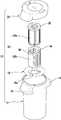
도 5는 본 발명에 의한 진공청소기의 먼지압축장치를 분해하여 나타낸 분해 사시도.5 is an exploded perspective view showing an exploded dust compression apparatus of the vacuum cleaner according to the present invention.
도 6a는 본 발명에 의한 진공청소기의 먼지압축장치가 집진유니트와 결합된 상태를 보인 사시도.Figure 6a is a perspective view showing a state in which the dust compression device of the vacuum cleaner according to the present invention is combined with the dust collecting unit.
도 6b는 본 발명에 의한 진공청소기의 먼지압축장치가 먼지압축시의 모습을 보인 사시도.Figure 6b is a perspective view showing the state of the dust compression device of the vacuum cleaner according to the present invention at the time of dust compression.
도 7은 본 발명에 의한 진공청소기 먼지압축장치의 요부구성인 분지부와 유로제어부가 청소 수행시의 결합상태를 보인 종단면도.Fig. 7 is a longitudinal sectional view showing a combined state of a branch part and a flow path control part of the vacuum cleaner dust compression apparatus according to the present invention when cleaning is performed.
도 8은 본 발명에 의한 진공청소기 먼지압축장치의 요부구성인 분지부와 유로제어부가 먼지 압축시의 결합상태를 보인 종단면도.Fig. 8 is a longitudinal sectional view showing a combined state of the branch part and the flow path control part of the vacuum cleaner dust compression apparatus according to the present invention during dust compression.
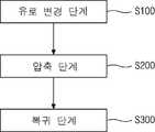
도 9는 본 발명에 의한 진공청소기 먼지압축방법의 흐름도.9 is a flow chart of a vacuum cleaner dust compression method according to the present invention.
* 도면의 주요 부분에 대한 부호의 설명 *Explanation of symbols on the main parts of the drawings
100. 흡입노즐체200. 본체100.
270. 집진장착부290. 토출부270.
300. 집진유니트310. 집진통300.
312. 흡입가이드314. 손잡이312.
316. 토출관320. 상면커버316.
322. 배기리브324. 착탈홈322.
350. 필터조립체360. 압축부350.
362. 분리판364. 슬라이더362.Separator 364. Slider
364'. 이탈방지플랜지368. 가이드364 '. Detachment flange 368.Guide
370. 분지부372. 메인유로370.
374. 모터연결유로376. 집진유로374.
378. 압축유로380. 유로제어부378.
382. 유로차폐봉384. 제어손잡이382. Euro Barrels 384. Control Knobs
390. 압축유도부392. 가로관390.
394. 압축부재396. 세로관394.
P . 먼지압축장치 S . 스프링 P. Dust Compressor S. spring
본 발명은 진공청소기에 관한 것으로, 보다 상세하게는 진공청소기 집진유니트의 내부에 집진된 이물을 압축하는 진공청소기의 먼지압축방법과 이러한 먼지압축에 사용되는 먼지압축장치에 관한 것이다.BACKGROUND OF THE INVENTION 1. Field of the Invention The present invention relates to a vacuum cleaner, and more particularly, to a dust compression method of a vacuum cleaner for compressing foreign matter collected in a vacuum cleaner dust collecting unit, and a dust compression device used for such a dust compression.
도 1에는 일반적인 업라이트형 진공청소기의 외관구성을 보인 사시도가 도시되어 있다.1 is a perspective view showing the external configuration of a general upright vacuum cleaner.
도시된 바와 같이 업라이트형 진공청소기는 바닥면을 따라 이동하면서 이물을 포함하는 공기를 흡입하는 흡입노즐체(60)와, 상기 흡입노즐체(60)를 통하여 이물을 포함하는 공기를 흡입하기 위한 흡입력을 발생하는 수단이 내장된 본체(70), 그리고 상기 본체(70)의 상부에 설치되고 청소기 사용시에 사용자가 파지하기 위한 조작부(72)를 포함하는 구성을 가진다.As shown in the upright vacuum cleaner, the
상기 흡입노즐체(60)의 외관은 하측에 구비되는 노즐하부커버(60')와 상측에 구비되는 노즐상부커버(60")로 구성되며, 상기 노즐하부커버(60')에 외부공기의 주(主)흡입통로가 되는 흡입구(미도시)가 형성된다. 그리고, 상기 흡입노즐체(60)의 양측에는 상기 본체(70)가 용이하게 이동하도록 하는 이동바퀴(62)가 구비됨이 일반적이다.The external appearance of the
상기 본체(70)는 흡입노즐체(60)에 대하여 일정각도 범위 내에서 회동 가능하도록 구성된다. 즉, 상기 본체(70)는 흡입노즐체(60)에 대하여 후방으로 일정한 경사각도의 범위 내에서 회동 가능하도록 결합되는데, 이러한 본체(70)의 회동을 제어하기 위해 상기 흡입노즐체(60)의 상면 후단부에는 회동레버(64)가 구비된다.The
또한, 상기 본체(70)의 전면에는 상기 집진유니트(10)를 본체(70) 외부로 인출시 사용되는 착탈노브(76)와, 상기 본체(70)의 후방으로 일정부분 함몰된 집진장착부(78)가 형성된다. 상기 집진장착부(78) 내부에는 상기 집진유니트(10)가 선택적으로 착탈 가능하도록 삽입된다. 그리고, 상기 집진장착부(78)의 하부에는 사용자에 의해서 선택적으로 점등 가능하도록 구비되어 청소기 전방을 밝혀주는 램프(L)가 설치된다.In addition, the front surface of the
그리고, 상기 램프(L)의 우측면(도 1에서 볼 때)에는 상기 집진유니트(10)에서 필터링 된 공기가 상기 본체(70) 외부로 토출되도록 하는 토출부(79)가 구비된다. 그리고, 상기 토출부(79)의 내측에는 배기필터(미도시)가 구비되어 외부(실내공간)로 토출되는 공기의 이물을 다시 걸러냄으로써 실내공간으로 보다 쾌적한 공기가 배출되도록 한다.In addition, a
도 2에는 일반적인 진공청소기용 집진유니트를 분해하여 나타낸 분해 사시도가 도시되어 있다. 도면에 도시된 바와 같이, 상기 집진유니트(10)에는 크게 원통모양으로 형성되어 이물이 집진되는 집진통(11)과, 상기 집진통(11)의 상면에 선택적으로 착탈 가능하도록 구비되어 상기 집진통(11)의 내부를 차폐하는 상면커버(20)로 구성되며, 상기 집진통(11)의 외주면에는 흡입가이드(14)가 형성된다.2 is an exploded perspective view showing an exploded dust collecting unit for a general vacuum cleaner. As shown in the figure, the
상기 흡입가이드(14)는 일단이상기 집진통(11)의 외측으로 소정부분 돌출되고 내부가 천공 형성되어, 상기 집진통(11) 내부로 유입되는 공기가 집진통(11)의 내벽을 따라 접선방향으로 유동할 수 있도록 안내한다. 따라서 상기 흡입가이드(14)는 상기 집진통(11)의 외면에 비스듬히 일정부분 경사지게 형성된다.One end of the suction guide 14 A predetermined portion protrudes to the outside of the
상기 흡입가이드(14)의 타측 외주면에는 상방으로 함몰 성형된 손잡이(15)가 형성된다. 상기 손잡이(15)는 사용자가 상기 진공청소기의 본체(70)로부터 집진유니트(10)를 착탈시에 용이하게 파지할 수 있도록 하기 위함이다.The other outer peripheral surface of the
상기 집진통(11)의 내측면에는 유입된 이물 중에서 상대적으로 질량이 큰 이물이 하측에 분리될 수 있도록 하는 분리판(16)이 성형된다. 즉, 상기 분리판(16)의 외주면에 형성되어 상기 집진통(11)의 상부와 하부가 연통되도록 하는 낙하부(16a)에 의해서 질량이 큰 이물은 상기 집진통(11)의 하측에 낙하되어 쌓이게 된다. 즉, 상기 분리판(16)은 상기 집진통(11)의 내부공간을 상·하로 구획한다.The inner side surface of the
상기 상면커버(20)와 분리판(16) 사이에는 집진유니트(10) 내부에 유입된 이물중에 미세한 먼지를 필터링하는 필터조립체(30)가 구비된다. 상기 필터조립체(30)는 내부필터(30a) 및 외부필터(30b)로 크게 구성되며, 상기 외부필터(30b)는 내부필터(30a)를 수용한 상태로 상기 상면커버(20)에 착탈 가능하게 장착된다.A
상기 내부필터(30a)는 대략 내부가 천공된 원통형상으로 성형되어, 집진통(11)내부로 유입된 이물중에서 미세한 이물을 필터링하는 역할을 수행한다. 그리고, 상기 내부필터(30a)의 상·하부에는 탄성부재로 성형되어 상기 내부필터(30a)가 상대물과 압착되도록 함으로써 공기 누설을 방지하는 씰링부(32)가 구비된다.The
한편, 외부필터(30b)는 상기 내부필터(30a)의 외경보다 조금 큰 내경을 가지고 대략 원통모양으로 성형된다. 그리고 상기 외부필터(30b)의 상부 외주면에는 소 정의 길이로 돌출 성형되어 상기 외부필터(30b)가 상기 상면커버(20)의 저면에 결합되도록 하는 체결리브(34)와, 상기 외부필터(30b)의 회동범위가 제한되도록 하는 정지돌기(36)가 구비된다.On the other hand, the
그러나, 상기와 같은 종래의 구성에서는 다음과 같은 문제점이 있다.However, the above conventional configuration has the following problems.
즉, 집진통(11)의 내부 공간은 한정되어 있으므로 청소 수행시에 집진된 이물을 자주 비워야하는 불편함이 있다.That is, since the internal space of the
또한, 집진통(11) 내부의 이물을 비울시에 먼지가 비산되어 사용편의성이 저하되므로 바람직하지 못하다.In addition, dust is scattered when the foreign matter inside the
상기와 같은 종래 기술에서의 문제점을 해결하기 위한 본 발명의 목적은, 모터에 의해 발생된 흡입력의 유동 경로를 변경하여 집진유니트 내부에 집진된 이물을 압축함으로써, 제한된 집진통 내부공간의 효율을 높이고, 먼지를 비울시에 먼지의 비산이 방지되도록 하는 진공청소기의 먼지압축방법과 이러한 먼지압축에 사용되는 먼지압축장치를 제공하는 것에 있다.An object of the present invention for solving the above problems in the prior art, by changing the flow path of the suction force generated by the motor to compress the foreign matter collected in the dust collection unit, thereby increasing the efficiency of the limited space inside the dust collector In addition, the present invention provides a method of compressing dust in a vacuum cleaner that prevents dust from scattering when emptying dust, and a dust compressing apparatus used for such dust compression.
상기와 같은 목적을 달성하기 위한 본 발명의 특징에 따르면, 본 발명은진공청소기 집진유니트의 일측에 구비된 분지부의 유로를 선택적으로 개방하여 공기유동경로를 변경하는 유로변경단계와; 흡입력을 발생하는 모터에 전원을 인가하여, 상기 집진유니트(300) 내부의 공기를 배출시킴으로써, 상기 집진유니트 내부에 구비된 분리판으로 집진된 이물을 압축하는 압축단계와; 상기 모터에 전원을 차단하여 상기 분리판이 원위치로 복귀되도록 하는 복귀단계를 포함하는 것을 특징으로 한다.According to a feature of the present invention for achieving the above object, the present invention A flow path changing step of selectively opening the flow path of the branch part provided on one side of the vacuum cleaner dust collecting unit to change the air flow path; A compression step of compressing foreign matter collected by a separator provided in the dust collecting unit by applying power to a motor generating suction force and discharging the air inside the
한편, 본 발명에 의한 진공청소기의 먼지압축장치는, 다수개의 유로가 분지되어 형성되고, 상기 유로의 일측은 흡입력을 발생하는 모터와 이물을 집진하는 집진유니트에 각각 연결되어 공기의 유동을 안내하는 분지부와; 상기 분지부의 내부에 회동 가능하도록 삽입되어 상기 유로의 개방을 선택적으로 제어하는 유로제어부와; 상기 분지부의 일측과 일단이 연통되도록 연결되고, 타단은 상기 집진유니트의 일측과 연통되어 상기 집진유니트 내부의 이물을 압축시에, 상기 집진유니트 내부의 공기 배출을 안내하는 압축유도부와; 상기 집진유니트의 내부 일측에 탄성력을 가지도록 구비되고, 공기가 상기 압축 유도부(390)로 배출되는 과정에서 하방으로 유동함으로써 상기 집진유니트 내부의 이물을 압축하는 압축부를 포함하여 구성됨을 특징으로 한다.On the other hand, the dust compressor of the vacuum cleaner according to the present invention, a plurality of flow paths are formed by branching, one side of the flow path is connected to a motor generating a suction force and a dust collecting unit for collecting foreign matter respectively to guide the flow of air Branches; A flow path control part inserted into the branch part to be rotatable to selectively control the opening of the flow path; One end of the branch portion is connected to communicate with each other, and the other end communicates with one side of the dust collecting unit to compress the foreign material in the dust collecting unit, and guides the air discharge inside the dust collecting unit; It is provided to have an elastic force on one side of the dust collection unit, characterized in that it comprises a compression unit for compressing the foreign matter inside the dust collection unit by flowing downward in the process of air is discharged to the
이와 같은 구성에 의하면, 집진유니트 내부의 이물을 압축하여 집진유니트의 한정된 내부공간을 효율적으로 활용함으로써 사용편의성이 증대되는 이점이 있다.According to such a configuration, there is an advantage in that the convenience of use is increased by compressing the foreign matter inside the dust collecting unit and efficiently utilizing the limited internal space of the dust collecting unit.
도 3에는 본 발명의 바람직한 실시예가 채용된 업라이트형 진공청소기의 외관 구성을 나타낸 사시도가 도시되어 있다. 그러나, 종래기술에 의한 업라이트형 진공청소기의 외관 구성과 동일하므로 별도의 구성 설명은 생략하기로 한다.3 is a perspective view showing an external configuration of an upright vacuum cleaner employing a preferred embodiment of the present invention. However, since it is the same as the external configuration of the upright vacuum cleaner according to the prior art, a description of a separate configuration will be omitted.
이하에서는 본 발명에 의한 먼지압축장치의 구성을 도면을 참조하여 살펴보기로 한다. 도 4에는 본 발명의 바람직한 실시예가 채용된 진공청소기용 집진유니트를 분해하여 나타낸 분해 사시도가 도시되어 있다. 도면에 도시된 바와 같이 상기 집진유니트(300)는 집진장착부(270)의 내부에 착탈 가능하게 장착되어, 상기 흡입노즐체(100)로부터 흡입되는 공기중의 이물을 필터링하는 역할을 수행한다.Hereinafter, the configuration of the dust compression apparatus according to the present invention will be described with reference to the drawings. 4 is an exploded perspective view showing an exploded view of a dust collecting unit for a vacuum cleaner employing a preferred embodiment of the present invention. As shown in the figure, the
상기 집진유니트(300)는 일반적으로 싸이클론 방식에 의하여 이물을 걸러내거나, 별도의 필터를 통하여 이물을 걸러서 포집하거나, 또는 싸이클론방식 및 필터방식을 동시에 실시하여 이물을 그 내부에 포집할 수 있도록 구성된다.The
상기 집진유니트(300)는 크게 원통모양으로 형성되어 이물이 집진되는 집진통(310)과, 상기 집진통(310)의 상면에 선택적으로 착탈 가능하도록 구비되어 상기 집진통(310)의 내부를 차폐하는 상면커버(320)를 포함하여 구성된다.The
상기 집진통(310)의 외주면에는 흡입가이드(312)가 형성된다. 상기 흡입가이드(312)는 일단이 상기 집진통(310)의 외측으로 소정부분 돌출되며, 집진통(310) 내부로 유입되는 공기가 집진통(310)의 내벽을 따라 접선방향으로 유동할 수 있도록 안내한다. 따라서 상기 흡입가이드(312)는 상기 집진통(310)의 외면에 비스듬히 일정부분 경사지게 형성된다.The
그리고, 상기 흡입가이드(312)의 타측 외주면에는 상방으로 함몰 성형된 손잡이(314)가 형성된다. 상기 손잡이(314)는 사용자가 상기 본체(200)로부터 집진유니트(300)를 착탈시에 용이하게 파지할 수 있도록 하기 위함이다.In addition, a
상기 집진통(310)의 하부 외주면에는 관형상을 가지고 상기 집진통(310) 내부로 연통되는 토출관(316)이 형성된다. 상기 토출관(316)은 상기 집진통(310)의 내부에서 절곡 성형되어 소정의 높이를 가지며, 상기 토출관(316)의 내부에는 아래에서 설명할 스프링(S)이 삽입된다. 그리고, 절곡 성형부의 일측에는 아래에서 상세히 설명할 압축부(360)가 장착된다.A
상기 상면커버(320)의 중앙에는 소정의 높이로 돌출되고 그 내부가 천공된 배기리브(322)가 구비된다. 상기 배기리브(322)는 집진유니트(300) 내부에서 필터링된 공기가 상부로 배기되도록 안내하게 된다. 상기 배기리브(322)의 전방에는 소정의 깊이로 함몰 성형된 착탈홈(324)이 구비된다. 상기 착탈홈(324)은 착탈노브(260)에 의해서 구속됨으로써 상기 집진유니트(300)가 상기 본체(200)의 외부로 이탈되지 않도록 구속하게 된다.An
한편, 상기 상면커버(320)의 하부에는 상기 집진유니트(300) 내부에 유입된 이물중에서 미세한 먼지를 필터링하는 필터조립체(350)가 구비된다. 상기 필터조립체(350)는 상면커버(320)의 저면에 착탈 가능하게 장착되며, 크게 내부필터(350a) 및 외부필터(350b)를 포함하여 구성된다.On the other hand, the lower portion of the
상기 필터조립체(350)는 공기가 강하게 유동되는 것을 고려하여 일정 이상의 강도가 확보되고, 세척시 형태를 유지할 수 있는 재질의 것으로 성형됨이 바람직하다. 예를 들면, 섬유재로 활용이 가능한 폴리에스테르 등의 플라스틱재질로 형성할 수도 있다.The
상기 내부필터(350a)는 대략 내부가 천공된 원통형상으로 성형되어, 상기 집진통(310)내부로 유입된 이물중에서 미세한 이물을 필터링하는 역할을 수행한다. 그리고, 상기 내부필터(350a)의 하부 일측에는 탄성부재로 성형되어, 상기 내부필터(350a)가 외부필터(350b)의 일측과 압착되도록 함으로써 공기 누설이 방지되도록 하는 씰링부(352)가 구비된다.The
그리고, 상기 내부필터(350a)의 상부 일측에는 필터조립체(350)를 상기 상면커버(320)에 장착시에 상기 필터조립체(350)의 회동범위가 제한되도록 하는 정지돌 기(354)와, 상기 내부필터(350a)가 상기 외부필터(350b)의 내부에서 유동되지 않도록 고정하는 고정돌기(355)가 구비된다.On the upper side of the
상기 외부필터(350b)는 상기 내부필터(350a)의 외경보다 조금 큰 내경을 가지는 원통모양으로 성형된다. 상기 외부필터(350b)의 상부에는 외주방향으로 돌출 성형되어 상기 외부필터(350b)가 상면커버(320) 저면에 결합되도록 하는 체결리브(358)와, 상기 정지돌기(354)가 안착되도록 함몰 성형된 안착홈(356), 상기 고정돌기(355)가 삽입되어 내부필터(350a)의 회동을 구속하는 고정홈(359)이 구비된다.The
한편, 상기 필터조립체(350)의 하부에는 본 발명의 요부구성인 압축부(360)가 설치된다. 상기 압축부(360)는 상기 집진유니트(300)의 내부 공간을 상하로 구획하는 분리판(362)과, 상기 분리판(362)의 저면에 결합된 원통모양의 슬라이더(364)와, 상기 슬라이더(364)의 하단부를 구속하며 상기 슬라이더(364)의 상하 유동을 안내하는 가이드(368)와, 상기 가이드(368)의 내부에서 소정의 탄성력을 발생하는 스프링(S)을 포함하는 구성을 가진다.On the other hand, the lower portion of the
상기 분리판(362)은 집진유니트(300) 내부 중앙에 위치하며 상기 분리판(362) 하측에 낙하된 무거운 이물이 상기 분리판(362) 상측으로 역행하지 않도록 차폐하는 역할과, 이물제거장치 작동시에 이물을 압축하는 역할을 동시에 수행하게 된다.The
그리고, 상기 분리판(362)의 일측에는 상기 흡입가이드(312)로부터 유입된 이물을 포함하는 공기가 상기 집진통(310)의 내주면을 따라서 맴돌이되다가 상기 집진통(310)의 하부로 낙하되도록 안내하는 낙하부(362')가 형성된다. 따라서 상기 낙하부(362')는 공기의 유동방향에 대하여 대응되도록 개구됨이 바람직하다.In addition, one side of the
상기 분리판(362)의 저면에는 상기 슬라이더(364)의 상단부가 스크류 결합된다. 따라서, 상기 분리판(362)이 먼지압축을 위해 하방으로 유동시에 상기 슬라이더가 동시에 유동 가능하게 된다.An upper end of the
상기 슬라이더(364)의 하단부에는 외주방향으로 소정의 길이를 가지고 돌출 성형된 이탈방지플랜지(364')가 구비된다. 상기 이탈방지플랜지(364')는 상기 슬라이더(364)와 일체로 성형되어 아래에서 설명할 가이드(368)의 일측에 간섭됨으로써 상기 슬라이더(364)가 가이드(368) 상방으로 이탈되지 않도록 구속하게 된다.A lower end portion of the
그리고, 상기 슬라이더(364)의 하부에는 상기 가이드(368)가 구비된다. 상기 가이드(368)는 슬라이더(364)의 상하 유동을 가이드하는 것으로, 그 내경크기는 상기 이탈방지플랜지(364')의 외경과 대응되며, 상단부의 내경은 상기 슬라이더(364)의 외경보다 조금 크게 형성된다. 따라서, 상기 이탈방지플랜지(364')는 가이드(368)의 상부 저면에 간섭되어 상기 슬라이더(364)의 이탈이 방지되는 것이다.The
상기 가이드(368)의 내부에는 소정의 탄성력을 가지는 스프링(S)이 구비된다. 상기 스프링(S)은 슬라이더(364)를 상방으로 탄성 지지함으로써 상기 분리판(362)이 상기 집진유니트(300) 내부에서 항상 중앙에 위치하도록 지지하며, 상기 분리판(362)의 하방 유동에 의해서 먼지압축이 완료시에 탄성복원력으로 상기 분리판(362)을 원위치로 복귀시키게 된다.A spring S having a predetermined elastic force is provided inside the
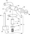
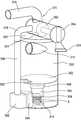
한편, 상기 본체의 내부 일측에는 먼지압축장치(P)가 더 구비된다. 도 5에는 본 발명에 의한 진공청소기의 먼지압축장치를 분해하여 나타낸 분해 사시도가 도시 되어 있고, 도 6a에는 본 발명에 의한 진공청소기의 먼지압축장치가 집진유니트와 결합된 상태를 보인 사시도가 도시되어 있으며, 도 6b에는 본 발명에 의한 진공청소기의 먼지압축장치가 먼지압축시의 모습을 보인 사시도가 도시되어 있다.On the other hand, the inner side of the main body is further provided with a dust compression device (P). 5 is an exploded perspective view showing an exploded view of the dust compressor of the vacuum cleaner according to the present invention, and FIG. 6A is a perspective view showing a state in which the dust compression device of the vacuum cleaner according to the present invention is coupled with a dust collecting unit. 6B is a perspective view showing a state in which the dust compression device of the vacuum cleaner according to the present invention is compressed.
이들 도면에 도시된 바와 같이, 상기 먼지압축장치(P)는 다수개의 유로가 분지되어 형성된 분지부(370)와, 상기 분지부의 내부에 회동 가능하도록 삽입되어 상기 유로의 개방을 선택적으로 제어하는 유로제어부(380)와, 상기 분지부와 토출관에 양단부가 연통되어 이물 압축시에 공기유동을 안내하는 압축유도부(390)와 전술한 압축부(360)를 포함하여 구성된다.As shown in these figures, the dust compression device (P) is a
상기 분지부(370)는 흡입력을 발생하는 모터(미도시)와 상기 집진유니트(300)에 각각 연결되어 공기의 유동을 안내하는 역할을 수행하며, 상기 분지부(370)의 우측 하부에는 메인유로(372)가 구비된다. 상기 메인유로(372)는 일단이 차폐된 원통형상을 가지고 그 내부에 상기 유로제어부(380)를 수용하여 공기 흐름방향을 제어할 수 있도록 하는 것으로 상기 집진장착부(270)의 상부에 장착된다.The
상기 메인유로(372)의 상부 외주면에는 대략 'ㄱ'모양으로 절곡 형성되어 상기 모터와 메인유로(372)의 내부공간이 연통되도록 연결하는 모터연결유로(374)가 형성된다. 상기 모터연결유로(374)에는 상기 모터에 의해서 발생된 흡입력이 전달되어 집진유니트(300)에서 이물이 필터링되도록 안내할 뿐만 아니라 먼지압축장치(P)의 작동시에도 상기 모터와 연결된 상태를 유지하게 된다.The upper outer circumferential surface of the
상기 메인유로(372)의 하부 외주면에는 집진유로(376)가 형성된다. 상기 집진유로(376)는 상기 상면커버(320)에 구비된 배기리브(322)에 대응되는 크기로 천 공 성형되어, 상기 집진유니트(300)가 집진장착부(270)에 삽입 장착시에 상기 배기리브(322)와 연통되도록 접촉하며, 상기 집진유니트(300)에 의해서 필터링된 공기가 상부로 배기되도록 안내하게 된다.A
상기 메인유로(372)의 좌측(도 5에서 볼 때) 외주면에는 내부가 천공된 상태로 '┎' 모양으로 절곡 성형된 압축유로(378)가 구비된다. 상기 압축유로(378)는 상기 압축유도부(390)의 상단부와 연결됨으로써 상기 모터압축장치(P)가 작동시에 상기 모터에서 발생된 흡입력이 상기 집진유니트(300)의 하부로 전달되도록 유도하게 된다.On the left side (as shown in FIG. 5) of the
한편, 상기 유로제어부(380)는 메인유로(372)의 내부에 삽입된 상태로 소정의 각도만큼 회동하여 상기 압축유로(378)와 집진유로(376)를 선택적으로 차폐하는 유로차폐봉(382)과, 상기 유로차폐봉(382)의 단부에서 연장 형성되고 상기 진공청소기의 외부로 노출(도 3 참조)되어, 사용자가 상기 유로차폐봉(382)을 선택적으로 회동 가능하도록 하는 제어손잡이(384)를 포함하여 구성된다.On the other hand, the
상기 유로차폐봉(382)은 상기 모터의 흡입력 손실을 방지하기 위해 상기 메인유로(372) 내부에 삽입된 상태에서 소정의 밀폐력을 포함함이 바람직하며, 이를 위하여 상기 유로차폐봉(382)과 메인유로(372)가 억지끼움방식으로 결합되거나, 상기 유로차폐봉(382)의 외주면 일측에 밀폐력을 가지는 고무재질의 탄성부재(미도시)를 구비할 수도 있을 것이다.The flow
즉, 상기 유로차폐봉(382)과 메인유로(372) 사이에 밀폐력이 발생된 상태에서 상기 유로차폐봉(382) 내부에 천공 형성된 '┬' 모양의 관이 소정의 각도로 회 동함으로써 상기 압축유로(378)와 집진유로(376)를 선택적으로 차폐 가능하게 되는 것이다.That is, the compression is performed by rotating a '┬' shaped tube formed in the
상기 압축유도부(390)는 대략 정육면체의 상자모양으로 형성되고 그 내부에 가로방향의 관이 형성된 가로관(392)과, 상기 가로관(392)의 상면에서 상부로 원통 형상을 가지고 연장 형성되어 상기 압축유로(378)의 단부와 결합되는 세로관(396)을 포함하여 구성된다.The
상기 가로관(392)의 우측단부는 상기 집진통(310)의 내부 하측에 형성된 토출관(316)의 단부와 대응되도록 형성되며, 상기 집진장착부(270)의 내부공간으로 노출(도 3 참조)됨으로써, 상기 집진유니트(300)를 집진장착부(270)에 장착시에 상기 토출관(316)에 삽입된다. 따라서 상기 가로관(392)의 우측면을 둘러서 공기 누설의 방지를 위해 고무재질로 형성된 압착부재(394)가 구비됨이 바람직하다.The right end of the
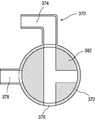
이하에서는 상기와 같이 구성되는 진공청소기 및 먼지압축장치의 작용에 대하여 도 3 내지 도 9를 참조하여 상세히 살펴보기로 한다. 도 7과 도 8에는 본 발명에 의한 진공청소기 먼지압축장치의 요부구성인 분지부와 유로제어부가 청소 수행시와 먼지 압축시의 결합상태를 보인 종단면도가 도시되어 있으며, 도 9에는 본 발명에 의한 진공청소기 먼지압축방법의 흐름도가 도시되어 있다.Hereinafter, the operation of the vacuum cleaner and the dust compression device configured as described above will be described in detail with reference to FIGS. 3 to 9. 7 and 8 are a longitudinal cross-sectional view showing a combined state of the branch portion and the flow path control unit when the cleaning and dust compression, which is a main component of the vacuum cleaner dust compression apparatus according to the present invention, and FIG. The flow chart of the vacuum cleaner dust compression method is shown.
먼저, 전원을 인가하여 진공청소기를 작동시키면, 상기 본체(200)에 내장된 모터(미도시)에 의해 흡입력이 발생된다. 이렇게 흡입력이 발생되면 상기 흡입노즐체(100)에 의하여 이물을 포함한 공기가 흡입되고, 흡입된 이물을 포함한 공기는 상기 집진유니트(300)의 흡입가이드(312)를 통해서 집진통(310) 내부로 유입된다.First, when a vacuum cleaner is operated by applying power, suction power is generated by a motor (not shown) built in the
이때, 상기 유로차폐봉(382)의 내부에 형성된 '┰'형 관은 도 7과 같이 '├'와 같은 상태로 놓이게 되어 상기 모터연결유로(374)와 집진유로(376)는 연통되며, 상기 압축유로(378)는 차폐된다.At this time, the '┰' type tube formed in the
상기 흡입가이드(312)를 통해서 집진통(310) 내부로 유입된 이물을 포함하는 공기는 상기 집진통(310)의 내벽을 따라서 회전하면서 맴돌이되며 상대적으로 질량이 큰 이물은 상기 낙하부(342)를 통과하여 분리판(340)의 하측에 쌓이게 되고, 상대적으로 질량이 적은 이물은 상기 필터조립체(350)의 외주면을 따라 회전하다가 상기 필터조립체(350)에 의해서 필터링된다.The air containing the foreign matter introduced into the
상기 필터조립체(350)를 통과한 공기는 상기 배기리브(322)와 집진유로(376)를 지나 상기 모터연결유로(374)를 통과하면서 상기 집진유니트(300)의 외부로 배출된다. 상기 집진유니트(300)의 외부로 배출된 공기는 모터(미도시)를 경유한 다음 상기 본체(200)의 외면에 장착된 토출부(290)를 통해서 청소기 외부로 토출되면서 청소는 수행된다.Air passing through the
한편, 상기 집진통(310) 내부에 많은 이물이 쌓이게 되면 상기 먼지압축장치(P)를 작동시켜 이물을 압축시키게 된다. 상기 먼지압축장치(P)를 작동시키기 위해서는 먼저, 상기 본체(200)의 좌측면(도 3에서 볼 때)에 돌출된 제어손잡이(384)를 반시계방향으로 90°회전시키게 된다(S100:유로변경단계).On the other hand, when a large amount of foreign matter is accumulated inside the
이때, 상기 유로차폐봉(382)도 동시에 회동되어 도 8과 같은 상태 즉, 상기 집진유로(376)는 차폐되고 상기 압축유로(378)는 개방된 상태가 되며, 상기 압축유로(378)는 상기 모터연결유로(374)와 연통되게 된다.At this time, the flow
상기 제어손잡이(384)의 조작에 의해서 공기유동경로의 변경이 완료되면 흡입력을 발생하는 모터(미도시)에 전원을 인가하여, 상기 집진유니트(300) 내부에 구비된 분리판(362)으로 집진된 이물을 압축하게 된다(S200:압축단계)When the change of the air flow path is completed by the operation of the
이러한 압축단계(S200)는 상기 모터에서 발생된 흡입력이 상기 모터연결유로(374)와 유로차폐봉(382), 압축유로(378), 압축유도부(390)를 순차적으로 거쳐서 상기 집진통(310)의 하부에 전달됨으로써 실행되며, 상기 집진통(310)의 하부에 전달된 흡입력은 상기 분리판(362)이 하방으로 슬라이딩되도록 함으로써 상기 분리판(362)의 저면이 집진된 이물을 압축 가능하도록 한다.In the compression step (S200), the suction force generated by the motor is sequentially passed through the
그리고, 상기 분리판(362)이 하부로 슬라이딩됨과 동시에 상기 슬라이더(364)도 하방으로 유동되며, 상기 슬라이더(364)의 하단부에 절곡 성형된 이탈방지플랜지(364')는 도 6b와 같이 상기 스프링(S)을 하방으로 누름으로써 상기 스프링(S)에는 탄성복원력이 발생된다.The
상기 집진통(310) 내부의 이물이 압축 완료되면 상기 모터에 전원을 차단하여 상기 분리판(362)이 원위치로 복귀되도록 한다(S300:복귀단계). 즉, 상기 모터의 전원이 차단되면 상기 집진통(310) 하부에 작용하던 흡입력이 제거되어 상기 스프링(S)은 원상으로 복귀됨과 동시에 상기 이탈방지플랜지(364')를 상방으로 밀어올리게 되어 상기 분리판(362)은 도 6a와 같이 원상태로 회복된다.When the foreign material inside the
그런 다음, 상기 제어손잡이(384)를 다시 시계방향으로 90°회전시켜 상기 유로차폐봉(382)이 도 7과 같은 상태가 되도록 한다. 이로써 상기 먼지압축장치(P)의 작동은 완전히 완료되며, 청소 수행이 가능한 상태가 된다.Thereafter, the
그리고, 상기 먼지압축장치(P)는 청소 수행중에도 상기 제어손잡이(384)를 회동시켜 일시적으로 작동 가능함은 물론이다.In addition, the dust compressor P may be temporarily operated by rotating the
이러한 본 발명의 범위는 상기에서 예시한 실시예에 한정되지 않고, 상기와 같은 기술범위 안에서 당업계의 통상의 기술자에게 있어서는 본 발명을 기초로 하는 다른 많은 변형이 가능할 것이다.The scope of the present invention is not limited to the above-exemplified embodiments, and many other modifications based on the present invention will be possible to those skilled in the art within the above technical scope.
상기와 같은 본 발명에 의한 진공청소기의 먼지압축장치는 집진유니트 내부에 쌓인 이물이 제어손잡이를 회동하는 조작에 의해서 유로가 변경됨으로써 모터로부터 발생된 흡입력으로 압축되도록 구성하였다.The dust compressor of the vacuum cleaner according to the present invention as described above is configured to compress foreign matter accumulated in the dust collecting unit by suction force generated from the motor by changing the flow path by the operation of rotating the control handle.
따라서, 제한된 집진통의 내부 공간을 효율적으로 활용함으로써 청소 수행시에 집진된 이물을 자주 비워야하는 불편함이 해소되는 이점이 있다.Therefore, there is an advantage in that the inconvenience of frequently emptying the collected foreign matter during cleaning is effectively utilized by effectively utilizing the internal space of the limited dust collecting container.
그리고, 집진통 내부의 이물이 압축됨으로써 이물을 비울시에 발생되는 먼지의 비산이 방지되어 사용편의성이 증대되는 이점이 있다.In addition, since the foreign matter inside the dust collecting container is compressed, the dust generated when emptying the foreign matter is prevented, thereby increasing the convenience of use.
또한, 필터조립체로In addition, the filter assembly
뿐만 아니라, 모터의 흡입력을 이용하여 먼지를 압축하므로 사용자의 육체적 피로를 덜 수 있게되어 제품만족도 향상도 기대할 수 있다.In addition, by using the suction power of the motor to compress the dust can reduce the physical fatigue of the user can be expected to improve the product satisfaction.
Claims (8)
Translated fromKoreanPriority Applications (14)
| Application Number | Priority Date | Filing Date | Title |
|---|---|---|---|
| KR1020040105486AKR100869000B1 (en) | 2004-12-14 | 2004-12-14 | Dust compression method of vacuum cleaner and dust compression device of vacuum cleaner |
| EP07121397AEP1929917B1 (en) | 2004-12-14 | 2005-12-09 | Vacuum cleaner |
| ES05111927TES2351508T3 (en) | 2004-12-14 | 2005-12-09 | POWDER COLLECTION UNIT OF A VACUUM CLEANER AND DUST COMPRESSION PROCEDURE FOR A POWDER COLLECTION UNIT. |
| DE602005026463TDE602005026463D1 (en) | 2004-12-14 | 2005-12-09 | vacuum cleaner |
| DE602005024227TDE602005024227D1 (en) | 2004-12-14 | 2005-12-09 | Dust collector for vacuum cleaners and method for dust compaction for dust collectors |
| EP07121394AEP1929916B1 (en) | 2004-12-14 | 2005-12-09 | Vacuum cleaner |
| DE602005021406TDE602005021406D1 (en) | 2004-12-14 | 2005-12-09 | vacuum cleaner |
| EP05111927AEP1671570B1 (en) | 2004-12-14 | 2005-12-09 | Dust collecting unit of vacuum cleaner and dust compressing method for dust collecting unit |
| ES07121397TES2358450T3 (en) | 2004-12-14 | 2005-12-09 | VACUUM CLEANER. |
| US11/297,435US7481868B2 (en) | 2004-12-14 | 2005-12-09 | Dust compressing apparatus and method for dust collecting unit of vacuum cleaner |
| AT05111927TATE484992T1 (en) | 2004-12-14 | 2005-12-09 | DUST COLLECTOR FOR VACUUM CLEANERS AND METHOD FOR DUST COMPACTION FOR DUST COLLECTORS |
| RU2005138845/12ARU2311110C2 (en) | 2004-12-14 | 2005-12-13 | Dust compacting apparatus (versions) and method of dust compaction for dust collecting apparatus of vacuum cleaner |
| US11/929,219US7600293B2 (en) | 2004-12-14 | 2007-10-30 | Vacuum cleaner |
| US11/929,271US7510587B2 (en) | 2004-12-14 | 2007-10-30 | Vacuum cleaner |
Applications Claiming Priority (1)
| Application Number | Priority Date | Filing Date | Title |
|---|---|---|---|
| KR1020040105486AKR100869000B1 (en) | 2004-12-14 | 2004-12-14 | Dust compression method of vacuum cleaner and dust compression device of vacuum cleaner |
Related Child Applications (2)
| Application Number | Title | Priority Date | Filing Date |
|---|---|---|---|
| KR1020070099032ADivisionKR100936066B1 (en) | 2007-10-02 | 2007-10-02 | Vacuum cleaner |
| KR1020070099035ADivisionKR100936067B1 (en) | 2007-10-02 | 2007-10-02 | Vacuum cleaner |
Publications (2)
| Publication Number | Publication Date |
|---|---|
| KR20060067146A KR20060067146A (en) | 2006-06-19 |
| KR100869000B1true KR100869000B1 (en) | 2008-11-17 |
Family
ID=35811694
Family Applications (1)
| Application Number | Title | Priority Date | Filing Date |
|---|---|---|---|
| KR1020040105486AExpired - Fee RelatedKR100869000B1 (en) | 2004-12-14 | 2004-12-14 | Dust compression method of vacuum cleaner and dust compression device of vacuum cleaner |
Country Status (7)
| Country | Link |
|---|---|
| US (3) | US7481868B2 (en) |
| EP (3) | EP1671570B1 (en) |
| KR (1) | KR100869000B1 (en) |
| AT (1) | ATE484992T1 (en) |
| DE (3) | DE602005021406D1 (en) |
| ES (2) | ES2351508T3 (en) |
| RU (1) | RU2311110C2 (en) |
Families Citing this family (43)
| Publication number | Priority date | Publication date | Assignee | Title |
|---|---|---|---|---|
| KR100595564B1 (en)* | 2004-07-16 | 2006-07-03 | 엘지전자 주식회사 | Vacuum cleaner |
| KR100869003B1 (en)* | 2005-05-12 | 2008-11-17 | 엘지전자 주식회사 | Vacuum cleaner |
| KR100869004B1 (en)* | 2005-05-16 | 2008-11-17 | 엘지전자 주식회사 | Vacuum cleaner |
| US8978197B2 (en) | 2009-03-13 | 2015-03-17 | Lg Electronics Inc. | Vacuum cleaner |
| US8404034B2 (en) | 2005-12-10 | 2013-03-26 | Lg Electronics Inc. | Vacuum cleaner and method of controlling the same |
| US8281455B2 (en) | 2005-12-10 | 2012-10-09 | Lg Electronics Inc. | Vacuum cleaner |
| US8012250B2 (en) | 2005-12-10 | 2011-09-06 | Lg Electronics Inc. | Vacuum cleaner |
| US8544143B2 (en)* | 2005-12-10 | 2013-10-01 | Lg Electronics Inc. | Vacuum cleaner with removable dust collector, and methods of operating the same |
| US7749295B2 (en)* | 2005-12-10 | 2010-07-06 | Lg Electronics Inc. | Vacuum cleaner with removable dust collector, and methods of operating the same |
| US7785396B2 (en)* | 2005-12-10 | 2010-08-31 | Lg Electronics Inc. | Vacuum cleaner with removable dust collector, and methods of operating the same |
| US7987551B2 (en) | 2005-12-10 | 2011-08-02 | Lg Electronics Inc. | Vacuum cleaner |
| US7770253B2 (en)* | 2005-12-10 | 2010-08-10 | Lg Electronics Inc. | Vacuum cleaner with removable dust collector, and methods of operating the same |
| KR100876694B1 (en)* | 2006-09-06 | 2008-12-31 | 엘지전자 주식회사 | How to control the vacuum cleaner |
| US7882592B2 (en) | 2005-12-10 | 2011-02-08 | Lg Electronics Inc. | Vacuum cleaner |
| US20070289444A1 (en)* | 2006-06-14 | 2007-12-20 | Toshiba Tec Kabushiki Kaisha | Vacuum cleaner having a filter capable of collecting dust |
| KR20080000188A (en)* | 2006-06-27 | 2008-01-02 | 엘지전자 주식회사 | Dust collection unit of the vacuum cleaner |
| KR100789837B1 (en)* | 2006-07-18 | 2008-01-02 | 엘지전자 주식회사 | Cyclone dust collector |
| EP1906280A3 (en)* | 2006-09-28 | 2011-02-23 | Jtekt Corporation | Program writing method of numerical controller, numerical controller and cutting machine controlled thereby |
| US20100106852A1 (en)* | 2007-10-24 | 2010-04-29 | Kindig Bradley D | Systems and methods for providing user personalized media content on a portable device |
| EP1949842B1 (en) | 2007-01-24 | 2015-03-04 | LG Electronics Inc. | Vacuum cleaner |
| RU2375951C2 (en)* | 2007-01-24 | 2009-12-20 | ЭлДжи ЭЛЕКТРОНИКС ИНК. | Vacuum cleaner (versions) |
| EP1949967B1 (en) | 2007-01-24 | 2015-03-25 | LG Electronics Inc. | Dust collector of a vacuum cleaner |
| US20080264014A1 (en)* | 2007-04-30 | 2008-10-30 | Samsung Gwangju Electronics Co. Ltd. | Dust compressing apparatus of vacuum cleaner |
| US7785381B2 (en)* | 2007-04-30 | 2010-08-31 | Samsung Gwangju Electronics Co., Ltd. | Dust collecting apparatus with combined compacting and filter cleaning for a vacuum cleaner |
| US20080264015A1 (en)* | 2007-04-30 | 2008-10-30 | Samsung Gwangju Electronics Co., Ltd | Dust compressing apparatus of vacuum cleaner |
| US7611558B2 (en)* | 2007-04-30 | 2009-11-03 | Samsung Gwangju Electronics Co., Ltd. | Dust compressing apparatus of vacuum cleaner |
| KR100889109B1 (en)* | 2007-07-23 | 2009-03-17 | 엘지전자 주식회사 | Dust collection apparatus of vacuum cleaner |
| US20100132317A1 (en)* | 2008-11-21 | 2010-06-03 | Thien J Philip | Dust separator |
| GB2466625B (en)* | 2008-12-23 | 2012-10-03 | Vax Ltd | Dust receptacle for a vacuum cleaner |
| US20100192776A1 (en)* | 2009-02-03 | 2010-08-05 | Jang-Keun Oh | Dust separating apparatus having adjustable dust collecting space |
| US8528163B2 (en) | 2009-02-12 | 2013-09-10 | Lg Electronics Inc. | Vacuum cleaner |
| US8151409B2 (en) | 2009-02-26 | 2012-04-10 | Lg Electronics Inc. | Vacuum cleaner |
| US8713752B2 (en) | 2009-03-13 | 2014-05-06 | Lg Electronics Inc. | Vacuum cleaner |
| US8107983B2 (en)* | 2009-03-16 | 2012-01-31 | Telefonaktiebolaget L M Ericsson | Systems and method for coordinated multipoint downlink transmissions |
| US8370992B2 (en)* | 2009-11-01 | 2013-02-12 | Lg Electronics Inc. | Vacuum cleaner |
| US8474092B2 (en)* | 2009-11-01 | 2013-07-02 | Lg Electronics Inc. | Vacuum cleaner |
| US20120011679A1 (en)* | 2009-11-03 | 2012-01-19 | Lg Electronics Inc. | Vacuum cleaner |
| KR101750310B1 (en)* | 2010-12-28 | 2017-07-03 | 엘지전자 주식회사 | Vacuum Cleaner |
| WO2012113414A1 (en)* | 2011-02-22 | 2012-08-30 | Aktiebolaget Electrolux | Vacuum cleaner |
| USD673155S1 (en)* | 2011-06-16 | 2012-12-25 | Pfu Limited | Scanner |
| US8978207B2 (en)* | 2013-03-15 | 2015-03-17 | Electrolux Home Care Products, Inc. | Vacuum cleaner edge cleaning system |
| EP3323334B1 (en) | 2016-11-17 | 2019-06-05 | Black & Decker Inc. | Vacuum cleaner |
| KR102733608B1 (en)* | 2019-11-29 | 2024-11-21 | 엘지전자 주식회사 | Cleaner |
Citations (3)
| Publication number | Priority date | Publication date | Assignee | Title |
|---|---|---|---|---|
| KR950016642A (en)* | 1993-12-03 | 1995-07-20 | 이헌조 | Dust bag crimping device of vacuum cleaner |
| KR960001804B1 (en)* | 1993-12-31 | 1996-02-05 | 엘지전자주식회사 | Dust Compactor for Cyclone Vacuum Cleaner |
| KR100595564B1 (en) | 2004-07-16 | 2006-07-03 | 엘지전자 주식회사 | Vacuum cleaner |
Family Cites Families (9)
| Publication number | Priority date | Publication date | Assignee | Title |
|---|---|---|---|---|
| SE421171B (en) | 1980-04-18 | 1981-12-07 | Electrolux Ab | DEVICE BY A LIFT CLEANER |
| JPS5936520A (en) | 1982-08-26 | 1984-02-28 | Morita Kogyo Kk | Method for stowing dust by compression |
| JPH05317215A (en) | 1992-05-21 | 1993-12-03 | Mitsubishi Electric Home Appliance Co Ltd | Vacuum cleaner |
| KR960000180B1 (en) | 1993-06-15 | 1996-01-03 | 현대전자산업주식회사 | Resist Pattern Formation Method by Silation |
| JP3004536B2 (en) | 1994-05-30 | 2000-01-31 | シャープ株式会社 | Electric vacuum cleaner |
| JP3476076B2 (en)* | 2000-08-10 | 2003-12-10 | シャープ株式会社 | Electric vacuum cleaner |
| DE60121652T2 (en)* | 2000-03-24 | 2007-07-26 | Sharp K.K. | Electric vacuum cleaner |
| DE60237744D1 (en) | 2001-08-08 | 2010-11-04 | Panasonic Corp | Vacuum cleaner with dust sealants |
| JP4078154B2 (en) | 2002-08-29 | 2008-04-23 | 株式会社東芝 | Electric vacuum cleaner |
- 2004
- 2004-12-14KRKR1020040105486Apatent/KR100869000B1/ennot_activeExpired - Fee Related
- 2005
- 2005-12-09ESES05111927Tpatent/ES2351508T3/enactiveActive
- 2005-12-09EPEP05111927Apatent/EP1671570B1/ennot_activeNot-in-force
- 2005-12-09ESES07121397Tpatent/ES2358450T3/enactiveActive
- 2005-12-09USUS11/297,435patent/US7481868B2/enactiveActive
- 2005-12-09EPEP07121394Apatent/EP1929916B1/ennot_activeNot-in-force
- 2005-12-09DEDE602005021406Tpatent/DE602005021406D1/enactiveActive
- 2005-12-09DEDE602005026463Tpatent/DE602005026463D1/enactiveActive
- 2005-12-09DEDE602005024227Tpatent/DE602005024227D1/enactiveActive
- 2005-12-09EPEP07121397Apatent/EP1929917B1/ennot_activeNot-in-force
- 2005-12-09ATAT05111927Tpatent/ATE484992T1/ennot_activeIP Right Cessation
- 2005-12-13RURU2005138845/12Apatent/RU2311110C2/ennot_activeIP Right Cessation
- 2007
- 2007-10-30USUS11/929,271patent/US7510587B2/enactiveActive
- 2007-10-30USUS11/929,219patent/US7600293B2/enactiveActive
Patent Citations (3)
| Publication number | Priority date | Publication date | Assignee | Title |
|---|---|---|---|---|
| KR950016642A (en)* | 1993-12-03 | 1995-07-20 | 이헌조 | Dust bag crimping device of vacuum cleaner |
| KR960001804B1 (en)* | 1993-12-31 | 1996-02-05 | 엘지전자주식회사 | Dust Compactor for Cyclone Vacuum Cleaner |
| KR100595564B1 (en) | 2004-07-16 | 2006-07-03 | 엘지전자 주식회사 | Vacuum cleaner |
Also Published As
| Publication number | Publication date |
|---|---|
| ATE484992T1 (en) | 2010-11-15 |
| EP1929916B1 (en) | 2010-05-19 |
| US20060123750A1 (en) | 2006-06-15 |
| EP1929917B1 (en) | 2011-02-16 |
| US7600293B2 (en) | 2009-10-13 |
| KR20060067146A (en) | 2006-06-19 |
| US7481868B2 (en) | 2009-01-27 |
| ES2351508T3 (en) | 2011-02-07 |
| RU2311110C2 (en) | 2007-11-27 |
| DE602005026463D1 (en) | 2011-03-31 |
| US20080052870A1 (en) | 2008-03-06 |
| RU2005138845A (en) | 2007-06-20 |
| ES2358450T3 (en) | 2011-05-10 |
| EP1929917A2 (en) | 2008-06-11 |
| EP1671570B1 (en) | 2010-10-20 |
| EP1671570A1 (en) | 2006-06-21 |
| US7510587B2 (en) | 2009-03-31 |
| US20080052868A1 (en) | 2008-03-06 |
| EP1929916A2 (en) | 2008-06-11 |
| DE602005024227D1 (en) | 2010-12-02 |
| DE602005021406D1 (en) | 2010-07-01 |
| EP1929916A3 (en) | 2008-10-15 |
| EP1929917A3 (en) | 2008-10-15 |
Similar Documents
| Publication | Publication Date | Title |
|---|---|---|
| KR100869000B1 (en) | Dust compression method of vacuum cleaner and dust compression device of vacuum cleaner | |
| KR100871484B1 (en) | Dust collection unit for vacuum cleaner | |
| US7398578B2 (en) | Cyclone dust collecting device for use in a vacuum cleaner | |
| KR100880492B1 (en) | Dust collection unit for vacuum cleaner | |
| EP1825798B1 (en) | Vacuum cleaner and dust separator of the same | |
| KR101248722B1 (en) | Dust Collector and Vacuum Cleaner Having the Same | |
| KR102409218B1 (en) | Cyclone dust collector and vacuum cleaner having the same | |
| AU2007201420A1 (en) | Dust collector of vacuum cleaner | |
| CN109843137B (en) | Vacuum cleaner with a vacuum cleaner head | |
| KR100936067B1 (en) | Vacuum cleaner | |
| KR20220046312A (en) | Cleaner station, cleaner system including same, and residual dust removal method using the cleaner system | |
| KR100936066B1 (en) | Vacuum cleaner | |
| KR100996561B1 (en) | Vacuum cleaner | |
| KR100833360B1 (en) | Dust collection unit for vacuum cleaner | |
| KR101199662B1 (en) | Dust and dirt collecting unit for vacuum cleaner | |
| KR100932761B1 (en) | Dust collection assembly of vacuum cleaner | |
| KR101119407B1 (en) | Vacuum cleaner | |
| KR101257560B1 (en) | Auto cleaner | |
| KR20060018714A (en) | Dust collection unit of vacuum cleaner | |
| KR20060064116A (en) | Dust collection unit for vacuum cleaner | |
| KR20060107626A (en) | Dust collection assembly of vacuum cleaner | |
| KR20060064117A (en) | Dust collection unit for vacuum cleaner | |
| KR20060107627A (en) | Dust collection assembly of vacuum cleaner | |
| KR20060018014A (en) | Dust collection assembly of vacuum cleaner |
Legal Events
| Date | Code | Title | Description |
|---|---|---|---|
| PA0109 | Patent application | St.27 status event code:A-0-1-A10-A12-nap-PA0109 | |
| PG1501 | Laying open of application | St.27 status event code:A-1-1-Q10-Q12-nap-PG1501 | |
| A201 | Request for examination | ||
| PA0201 | Request for examination | St.27 status event code:A-1-2-D10-D11-exm-PA0201 | |
| A107 | Divisional application of patent | ||
| PA0107 | Divisional application | St.27 status event code:A-0-1-A10-A18-div-PA0107 St.27 status event code:A-0-1-A10-A16-div-PA0107 | |
| D13-X000 | Search requested | St.27 status event code:A-1-2-D10-D13-srh-X000 | |
| D14-X000 | Search report completed | St.27 status event code:A-1-2-D10-D14-srh-X000 | |
| E902 | Notification of reason for refusal | ||
| PE0902 | Notice of grounds for rejection | St.27 status event code:A-1-2-D10-D21-exm-PE0902 | |
| P11-X000 | Amendment of application requested | St.27 status event code:A-2-2-P10-P11-nap-X000 | |
| P13-X000 | Application amended | St.27 status event code:A-2-2-P10-P13-nap-X000 | |
| PN2301 | Change of applicant | St.27 status event code:A-3-3-R10-R13-asn-PN2301 St.27 status event code:A-3-3-R10-R11-asn-PN2301 | |
| E701 | Decision to grant or registration of patent right | ||
| PE0701 | Decision of registration | St.27 status event code:A-1-2-D10-D22-exm-PE0701 | |
| GRNT | Written decision to grant | ||
| PR0701 | Registration of establishment | St.27 status event code:A-2-4-F10-F11-exm-PR0701 | |
| PR1002 | Payment of registration fee | St.27 status event code:A-2-2-U10-U11-oth-PR1002 Fee payment year number:1 | |
| PG1601 | Publication of registration | St.27 status event code:A-4-4-Q10-Q13-nap-PG1601 | |
| R18-X000 | Changes to party contact information recorded | St.27 status event code:A-5-5-R10-R18-oth-X000 | |
| R18-X000 | Changes to party contact information recorded | St.27 status event code:A-5-5-R10-R18-oth-X000 | |
| PR1001 | Payment of annual fee | St.27 status event code:A-4-4-U10-U11-oth-PR1001 Fee payment year number:4 | |
| FPAY | Annual fee payment | Payment date:20121026 Year of fee payment:5 | |
| PR1001 | Payment of annual fee | St.27 status event code:A-4-4-U10-U11-oth-PR1001 Fee payment year number:5 | |
| FPAY | Annual fee payment | Payment date:20131024 Year of fee payment:6 | |
| PR1001 | Payment of annual fee | St.27 status event code:A-4-4-U10-U11-oth-PR1001 Fee payment year number:6 | |
| FPAY | Annual fee payment | Payment date:20141024 Year of fee payment:7 | |
| PR1001 | Payment of annual fee | St.27 status event code:A-4-4-U10-U11-oth-PR1001 Fee payment year number:7 | |
| PN2301 | Change of applicant | St.27 status event code:A-5-5-R10-R13-asn-PN2301 St.27 status event code:A-5-5-R10-R11-asn-PN2301 | |
| FPAY | Annual fee payment | Payment date:20151023 Year of fee payment:8 | |
| PR1001 | Payment of annual fee | St.27 status event code:A-4-4-U10-U11-oth-PR1001 Fee payment year number:8 | |
| PR1001 | Payment of annual fee | St.27 status event code:A-4-4-U10-U11-oth-PR1001 Fee payment year number:9 | |
| PR1001 | Payment of annual fee | St.27 status event code:A-4-4-U10-U11-oth-PR1001 Fee payment year number:10 | |
| PR1001 | Payment of annual fee | St.27 status event code:A-4-4-U10-U11-oth-PR1001 Fee payment year number:11 | |
| FPAY | Annual fee payment | Payment date:20191014 Year of fee payment:12 | |
| PR1001 | Payment of annual fee | St.27 status event code:A-4-4-U10-U11-oth-PR1001 Fee payment year number:12 | |
| PN2301 | Change of applicant | St.27 status event code:A-5-5-R10-R13-asn-PN2301 St.27 status event code:A-5-5-R10-R11-asn-PN2301 | |
| PR1001 | Payment of annual fee | St.27 status event code:A-4-4-U10-U11-oth-PR1001 Fee payment year number:13 | |
| PR1001 | Payment of annual fee | St.27 status event code:A-4-4-U10-U11-oth-PR1001 Fee payment year number:14 | |
| PC1903 | Unpaid annual fee | St.27 status event code:A-4-4-U10-U13-oth-PC1903 Not in force date:20221111 Payment event data comment text:Termination Category : DEFAULT_OF_REGISTRATION_FEE | |
| PC1903 | Unpaid annual fee | St.27 status event code:N-4-6-H10-H13-oth-PC1903 Ip right cessation event data comment text:Termination Category : DEFAULT_OF_REGISTRATION_FEE Not in force date:20221111 |