KR100868846B1 - Nano wire grid polarizer and its manufacturing method - Google Patents
Nano wire grid polarizer and its manufacturing methodDownload PDFInfo
- Publication number
- KR100868846B1 KR100868846B1KR1020060022408AKR20060022408AKR100868846B1KR 100868846 B1KR100868846 B1KR 100868846B1KR 1020060022408 AKR1020060022408 AKR 1020060022408AKR 20060022408 AKR20060022408 AKR 20060022408AKR 100868846 B1KR100868846 B1KR 100868846B1
- Authority
- KR
- South Korea
- Prior art keywords
- conductive metal
- metal layer
- pattern
- resin layer
- grid
- Prior art date
- Legal status (The legal status is an assumption and is not a legal conclusion. Google has not performed a legal analysis and makes no representation as to the accuracy of the status listed.)
- Expired - Fee Related
Links
Images


Classifications
- G—PHYSICS
- G02—OPTICS
- G02B—OPTICAL ELEMENTS, SYSTEMS OR APPARATUS
- G02B5/00—Optical elements other than lenses
- G02B5/30—Polarising elements
- G02B5/3025—Polarisers, i.e. arrangements capable of producing a definite output polarisation state from an unpolarised input state
- G02B5/3058—Polarisers, i.e. arrangements capable of producing a definite output polarisation state from an unpolarised input state comprising electrically conductive elements, e.g. wire grids, conductive particles
- B—PERFORMING OPERATIONS; TRANSPORTING
- B82—NANOTECHNOLOGY
- B82Y—SPECIFIC USES OR APPLICATIONS OF NANOSTRUCTURES; MEASUREMENT OR ANALYSIS OF NANOSTRUCTURES; MANUFACTURE OR TREATMENT OF NANOSTRUCTURES
- B82Y40/00—Manufacture or treatment of nanostructures
- G—PHYSICS
- G02—OPTICS
- G02B—OPTICAL ELEMENTS, SYSTEMS OR APPARATUS
- G02B5/00—Optical elements other than lenses
- G02B5/18—Diffraction gratings
- G02B5/1847—Manufacturing methods
- G—PHYSICS
- G02—OPTICS
- G02F—OPTICAL DEVICES OR ARRANGEMENTS FOR THE CONTROL OF LIGHT BY MODIFICATION OF THE OPTICAL PROPERTIES OF THE MEDIA OF THE ELEMENTS INVOLVED THEREIN; NON-LINEAR OPTICS; FREQUENCY-CHANGING OF LIGHT; OPTICAL LOGIC ELEMENTS; OPTICAL ANALOGUE/DIGITAL CONVERTERS
- G02F1/00—Devices or arrangements for the control of the intensity, colour, phase, polarisation or direction of light arriving from an independent light source, e.g. switching, gating or modulating; Non-linear optics
- G02F1/01—Devices or arrangements for the control of the intensity, colour, phase, polarisation or direction of light arriving from an independent light source, e.g. switching, gating or modulating; Non-linear optics for the control of the intensity, phase, polarisation or colour
- G02F1/13—Devices or arrangements for the control of the intensity, colour, phase, polarisation or direction of light arriving from an independent light source, e.g. switching, gating or modulating; Non-linear optics for the control of the intensity, phase, polarisation or colour based on liquid crystals, e.g. single liquid crystal display cells
- G02F1/133—Constructional arrangements; Operation of liquid crystal cells; Circuit arrangements
- G02F1/1333—Constructional arrangements; Manufacturing methods
- G02F1/1335—Structural association of cells with optical devices, e.g. polarisers or reflectors
- G02F1/133528—Polarisers
Landscapes
- Physics & Mathematics (AREA)
- Engineering & Computer Science (AREA)
- General Physics & Mathematics (AREA)
- Chemical & Material Sciences (AREA)
- Optics & Photonics (AREA)
- Manufacturing & Machinery (AREA)
- Crystallography & Structural Chemistry (AREA)
- Nanotechnology (AREA)
- Nonlinear Science (AREA)
- Condensed Matter Physics & Semiconductors (AREA)
- Mathematical Physics (AREA)
- Polarising Elements (AREA)
Abstract
Translated fromKoreanDescription
Translated fromKorean도 1은 통상적인 와이어 그리드 편광자의 작용원리를 나타낸 개략도;1 is a schematic view showing the principle of operation of a conventional wire grid polarizer;
도 2는 통상적인 반사형 편광자로서의 와이어 그리드 편광자의 작용원리를 더욱 상세히 나타낸 모식도;2 is a schematic diagram showing in more detail the principle of operation of a wire grid polarizer as a conventional reflective polarizer;
도 3은 통상적인 와이어 그리드 편광자의 개략적인 모양을 나타낸 모식도;3 is a schematic diagram showing a schematic shape of a conventional wire grid polarizer;
도 4는 종래기술에 따라 포토마스크 노광과 에칭법을 이용한 와이어 그리드 편광자의 제조공정을 나타낸 모식도;4 is a schematic diagram showing a manufacturing process of a wire grid polarizer using a photomask exposure and etching method according to the prior art;
도 5는 종래기술에 따라 나노 임프린팅법과 에칭법을 이용한 와이어 그리드 편광자의 제조공정을 나타낸 모식도;5 is a schematic diagram showing a manufacturing process of a wire grid polarizer using a nanoimprinting method and an etching method according to the prior art;
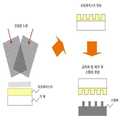
도 6은 간섭 리쏘그래피 방법을 이용하여 스템퍼를 제작하는 공정의 모식도;6 is a schematic diagram of a process for fabricating a stamper using an interference lithography method;
도 7은 본 발명의 일 실시형태에 따른 나노 와이어 그리드 편광자의 제조공정을 나타낸 모식도;7 is a schematic diagram illustrating a manufacturing process of a nanowire grid polarizer according to an embodiment of the present invention;
도 8은 본 발명의 다른 실시형태에 따른 나노 와이어 그리드 편광자의 제조공정을 나타낸 모식도; 및8 is a schematic diagram showing a manufacturing process of a nanowire grid polarizer according to another embodiment of the present invention; And
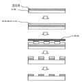
도 9는 본 발명의 실시형태에 따른 나노 와이어 그리드 편광자의 구조를 예시한 단면도.9 is a cross-sectional view illustrating a structure of a nanowire grid polarizer according to an embodiment of the present invention.
<도면의 주요 부분에 대한 부호의 설명><Explanation of symbols for the main parts of the drawings>
801, 901 : 기재801, 901
701, 802, 902 : 수지층701, 802, 902: resin layer
702, 803, 903 : 전도성 금속층702, 803, 903: conductive metal layer
703 : 점착필름703: adhesive film
710, 810 : 스템퍼710, 810: Stamper
904 : 보호층904: protective layer
본 발명은 나노 와이어 그리드 편광자 및 그 제조방법에 관한 것이다. 특히, 가시광선 영역에서 양호한 편광분리성능을 가지는 나노 크기의 와이어 그리드 편광자 및 그 제조방법에 대한 것이다.The present invention relates to a nano wire grid polarizer and a method of manufacturing the same. In particular, the present invention relates to a nano-sized wire grid polarizer having a good polarization separation performance in the visible light region and a manufacturing method thereof.
편광자 혹은 편광소자란 자연광과 같은 비편광된 빛 중에서 특정한 진동방향을 갖는 직선 편광을 끌어내는 광학소자를 의미한다. 광학소자 중의 한 종류인 와이어 그리드 편광자는도 1에 예시한 바와 같이 전도성 와이어 그리드(wire grid)를 이용하여 편광을 만들어내는 광학소자이다. 이는 다른 편광자에 비해 높은 편광분리성능을 가지기 때문에 110 여년 전부터 적외선 영역의 파장대에 있어 유용한 반사형 편광자로 사용되어 왔다.The polarizer or the polarizer refers to an optical device that derives linearly polarized light having a specific vibration direction among unpolarized light such as natural light. One type of optical device, the wire grid polarizer, is an optical device that generates polarized light using a conductive wire grid as illustrated in FIG. 1 . Since it has higher polarization separation performance than other polarizers, it has been used as a reflective polarizer useful in the wavelength range of the infrared region for more than 110 years.
즉,도 2와 같이 와이어 그리드 편광자는 와이어 그리드 간 간격, 즉 피치 (pitch)가 입사광의 파장보다 충분히 작을 경우 비편광 상태의 빛이 입사될 때 전도성의 와이어 그리드와 직교하는 벡터를 가지는 성분, 즉 P 편광(혹은 TM(Transverse Magnetic) 편광)은 투과하고 와이어 그리드와 평행한 벡터를 가지는 성분, 즉 S 편광(혹은 TE(Transverse Electric) 편광)은 반사시키게 된다. 하지만, 와이어 그리드 간 피치가 충분히 작지 못할 경우에는 입사광을 편광시키지 못하고 회절시키게 되어 원하는 효과를 기대하기 어렵게 된다.That is,as shown inFIG. 2 , the wire grid polarizer has a component having a vector orthogonal to the conductive wire grid when light in an unpolarized state is incident when the distance between the wire grids, that is, the pitch is smaller than the wavelength of the incident light, that is, P-polarized light (or Transverse Magnetic polarized light) transmits and reflects a component having a vector parallel to the wire grid, that is, S-polarized light (or Trans-electric Electric (TE) polarized light). However, when the pitch between the wire grids is not small enough, the incident light is not polarized and diffracted, making it difficult to expect a desired effect.
이러한 와이어 그리드 편광자의 성능을 결정하는 요인 중 가장 중요한 것으로는 와이어 그리드 간 간격 피치와 입사광 파장과의 관계이다.The most important factor that determines the performance of the wire grid polarizer is the relationship between the gap pitch between the wire grids and the incident light wavelength.
미국 특허 제6,122,103호 등의 문헌에 의해 알려진 바에 의하면,도 3과 같은 와이어 그리드 편광자에서 와이어 그리드의 피치(p)가 입사광 파장의 1/2에서 2배의 범위, 즉 전이영역(transition region)에 있을 때에는 특정 파장의 빛에 대해 편광분리성능이 크게 저하되는 것으로 알려져 있다. 즉, 레일리 공명(Rayleigh resonance)으로 알려진 이러한 현상에서 편광분리성능이 일어날 수 있는 가장 긴 파장은 다음과 같은 식으로 표현된다.As known from U.S. Patent No. 6,122,103 and the like, in the wire grid polarizer as shown inFIG. 3 , the pitch p of the wire grid is in the range of 1/2 to twice the incident light wavelength, that is, in the transition region. When present, it is known that polarization separation performance is greatly reduced for light of a specific wavelength. In other words, in this phenomenon known as Rayleigh resonance, the longest wavelength at which polarization separation performance can occur is expressed by the following equation.

여기서, p : 와이어 그리드 피치Where p is the wire grid pitch
n : 기재의 굴절률 n: refractive index of the substrate
θ : 빛의 입사각 θ: incident angle of light
즉, 와이어 그리드 편광자가 가시광선 영역에서 충분한 편광분리성능을 나타내기 위해서는 레일리 공명이 일어날 수 있는 최대 파장 λmax가 가시광선 영역 빛의 파장보다 짧아져야 한다. 예를 들면, 빛의 입사각이 75도 이내의 범위일 경우 양호한 편광분리성능이 나타날 수 있는 와이어 그리드 피치는 이론적으로 기재 굴절률에 따라 150nm ~ 200nm 정도가 최대값으로 알려져 있다.That is, in order for the wire grid polarizer to exhibit sufficient polarization separation performance in the visible light region, the maximum wavelength λmax that Rayleigh resonance can occur must be shorter than the wavelength of the visible light region. For example, when the angle of incidence of light is within a range of 75 degrees, the wire grid pitch that may exhibit good polarization separation performance is theoretically known to have a maximum value of about 150 nm to 200 nm depending on the refractive index of the substrate.
하지만, 이 정도의 피치를 가지는 나노 와이어 그리드를 제조하기 위해서는 고가의 마스크 제작이 필요하고 전자선이나 X-선 리쏘그래피 등 제조방법이 복잡하고 효율이 낮으며 대면적으로 제조하기 어려운 복잡한 공정이 필요하기 때문에 디스플레이용 액정표시장치 등에 사용될 수 없었으며 작은 크기의 광학소자로만 그 적용이 한정되어 왔다.However, in order to manufacture a nanowire grid having such a pitch, it is necessary to manufacture expensive masks, and complex manufacturing methods such as electron beams and X-ray lithography are complicated, low efficiency, and complicated processes that are difficult to manufacture in large areas. Therefore, it could not be used for a liquid crystal display device for a display and its application has been limited only to an optical element of a small size.
구체적으로, 종래의 와이어 그리드 편광자는 대표적으로 다음의 두 가지 방법으로 제조되었다.Specifically, conventional wire grid polarizers are typically manufactured by the following two methods.
하나의 방법은도 4에 예시되어 있다. 이 방법에 따르면, 유리나 석영 등의 무기물 기재에 전도성 금속막을 형성하고, 그 위에 포토레지스트층을 형성한 후, 이 포토레지스트층을 포토마스크에 의하여 선택적으로 노광하고 현상하여 패턴화한다. 이어서, 패턴화된 포토레지스트층을 이용하여 포토레지스트층의 아래에 적층된 전도성 금속막을 식각하여 전도성 금속막층을 패턴화한다. 이어서, 상기 포토레지스트층을 제거한다.One method is illustrated in FIG.4 . According to this method, a conductive metal film is formed on an inorganic substrate such as glass or quartz, a photoresist layer is formed thereon, and the photoresist layer is selectively exposed, developed and patterned by a photomask. Subsequently, the conductive metal film stacked below the photoresist layer is etched using the patterned photoresist layer to pattern the conductive metal film layer. Next, the photoresist layer is removed.
다른 하나의 방법은도 5에 예시되어 있다. 이 방법에 따르면, 무기물 기재 에 전도성 금속막을 형성하고 그 위에 포토레지스트층을 형성한 후, 이 포토레지스트층을 스템퍼에 의해 가압하여 변형시키고, 노광 및 현상에 의하여 패턴화한다. 이어서, 패턴화된 포토레지스트층을 이용하여 포토레지스트층의 아래에 적층된 전도성 금속막층을 식각하여 전도성 금속막층을 패턴화하고, 포토레지스트층을 제거한다.Another method is illustrated in FIG.5 . According to this method, after forming a conductive metal film on an inorganic substrate and forming a photoresist layer thereon, the photoresist layer is deformed by pressing with a stamper and patterned by exposure and development. Subsequently, the conductive metal film layer laminated under the photoresist layer is etched using the patterned photoresist layer to pattern the conductive metal film layer, and the photoresist layer is removed.
이와 같이, 종래 기술에 따른 와이어 그리드 편광자의 제조 방법은 전도성 금속막층을 패턴화하기 위하여 전도성 금속막층 상에 포토레지스트층 형성, 포토레지스트층의 패턴화, 및 포토레지스트층의 제거 단계를 거쳐야 하기 때문에 공정이 복잡하고 고비용인 문제가 있다. 또한, 종래기술의 방법에서 사용되는 포토마스크 또는 스템퍼는 전자빔이나 X선 등을 이용하여 제조되기 때문에 작은 면적으로 제조될 수밖에 없었다. 그러므로, 종래 기술에 의해서는 와이어 그리드 편광자를 대면적으로 제조할 수 없었다.As described above, the wire grid polarizer manufacturing method according to the related art requires a photoresist layer formed on the conductive metal film layer, a patterned photoresist layer, and a photoresist layer removed to pattern the conductive metal film layer. The process is complex and expensive. In addition, since the photomask or stamper used in the conventional method is manufactured by using an electron beam or X-ray, etc., it has to be manufactured with a small area. Therefore, the wire grid polarizer cannot be manufactured in a large area by the prior art.
따라서, 본 발명은 가시광선 영역에서 양호한 편광분리성능을 가지며, 저비용으로 대면적을 구현할 수 있는 나노 와이어 그리드 편광자 및 그 제조 방법을 제공하는 데 그 목적이 있다.Accordingly, an object of the present invention is to provide a nanowire grid polarizer having a good polarization separation performance in the visible light region and realizing a large area at low cost and a method of manufacturing the same.
상기의 기술적 과제를 달성하기 위하여, 본 발명은 수지층에 나노 크기로 그리드 패턴을 형성하는 단계와, 상기 패턴이 형성된 수지층 상면에 전도성 금속층을 형성하는 단계와, 상기 패턴의 볼록부에 형성된 전도성 금속층만을 선택적으로 제 거하는 단계를 포함하는 나노 와이어 그리드 편광자의 제조 방법을 제공한다.In order to achieve the above technical problem, the present invention comprises the steps of forming a grid pattern with a nano-sized resin layer, forming a conductive metal layer on the upper surface of the resin layer formed with the pattern, the conductivity formed in the convex portion of the pattern It provides a method of manufacturing a nano-wire grid polarizer comprising the step of selectively removing only the metal layer.
또한, 본 발명은 상기 방법에 의하여 제조된, 나노 크기로 그리드 패턴화된 수지층 및 상기 그리드 패턴화된 수지층 사이의 오목부에 형성된 전도성 금속층을 포함하는 나노 와이어 그리드 편광자를 제공한다.The present invention also provides a nanowire grid polarizer comprising the conductive metal layer formed in the recess between the grid patterned resin layer and the nano-scale patterned resin layer prepared by the method.
또한, 본 발명은 상기 방법에 의하여 제조된, 기재, 상기 기재 상면에 나노 크기로 그리드 패턴화된 전도성 금속층을 포함하는 나노 와이어 그리드 편광자를 제공한다.In another aspect, the present invention provides a nanowire grid polarizer comprising a substrate, a nano-scale grid patterned conductive metal layer prepared on the substrate, by the method.
이하, 본 발명을 상세히 설명한다.Hereinafter, the present invention will be described in detail.
본 발명의 제1 실시상태에 따른 나노 와이어 그리드 편광자는 지지체로 기능하는 기재, 상기 기재 상면에 나노 크기로 그리드 패턴화된 수지층 및 상기 그리드 패턴화된 수지층 사이의 오목부에 형성된 전도성 금속층을 포함하도록 구성된다.The nanowire grid polarizer according to the first exemplary embodiment of the present invention may include a substrate functioning as a support, a conductive metal layer formed on a concave portion between the grid patterned resin layer and the grid patterned resin layer having a nano size on an upper surface of the substrate. It is configured to include.
본 발명에 있어서, 상기 기재와 수지층은 일체로 형성되거나, 별도로 형성될 수 있다.In the present invention, the substrate and the resin layer may be integrally formed or separately formed.
상기 수지층을 기재와 일체로 형성하는 경우, 상기 수지층은 지지체의 역할을 함과 동시에 패턴이 형성될 수 있는 성형 수지 역할을 모두 할 수 있는 플라스틱과 같은 광학적으로 투명한 유기소재를 사용하는 것이 바람직하다. 상기 수지층의 비제한적인 예로는, 폴리에스터계, 폴리에테르설폰계, 폴리카보네이트계, 폴리에스터나프테네이트계 또는 우레탄아크릴레이트, 에폭시아크릴레이트, 에스터아크릴레이트 등을 포함하는 폴리아크릴레이트계 수지 등을 들 수 있다. 이와 같은 재료로 이루어진 수지층을 이용하는 경우 별도의 기재를 사용하지 않을 수 있다.When the resin layer is integrally formed with the substrate, it is preferable that the resin layer uses an optically transparent organic material such as plastic, which can both serve as a support and also serve as a molding resin in which a pattern can be formed. Do. Non-limiting examples of the resin layer is a polyester, polyether sulfone, polycarbonate, polyester naphthenate-based or polyacrylate-based resin including urethane acrylate, epoxy acrylate, ester acrylate, etc. Etc. can be mentioned. When using a resin layer made of such a material, a separate substrate may not be used.
상기 수지층을 기재와 별도로 형성하는 경우, 본 발명에 따른 나노 와이어 그리드 편광자는 기재 및 이 기재 상면에 나노 크기로 그리드 패턴화된 수지층을 포함하도록 구성된다.When the resin layer is formed separately from the substrate, the nanowire grid polarizer according to the present invention is configured to include a substrate and a resin pattern grid-patterned to a nano size on an upper surface of the substrate.
여기서, 상기 기재는 편광자의 지지체 역할을 하는 것으로서 광학적으로 투명한 유기 또는 무기물 소재인 것이 바람직하다. 특히, 유리, 또는 석영 등의 무기물, 또는 폴리에스터, 폴리염화비닐, 폴리카보네이트, 폴리메틸메타아크릴레이트, 폴리스타이렌, 폴리에스터설폰, 및 폴리에테르케톤 등에서 선택된 유기수지를 1종 단독 또는 2종 이상을 혼합하여 제조된 필름 또는 시트 형태인 것을 사용할 수 있다.Herein, the substrate serves as a support of the polarizer, and is preferably an optically transparent organic or inorganic material. In particular, an inorganic material such as glass or quartz, or an organic resin selected from polyester, polyvinyl chloride, polycarbonate, polymethyl methacrylate, polystyrene, polyester sulfone, and polyether ketone, etc. It may be used in the form of a film or sheet prepared by mixing.
또한, 상기 기재 상면에 형성되는 수지층은 나노 크기의 미세 패턴이 쉽게 형성될 수 있고, 상기 기재와의 접착이 우수하며, 스템퍼에 의해 미세 패턴을 형성하는 경우 경화 후 금형인 스템퍼로부터 용이하게 분리될 수 있도록 낮은 점도를 갖는 투명한 액상의 광경화성 수지인 것이 바람직하다. 그 바람직한 점도는 300cps 이하, 보다 바람직하게는 100 ~ 200 cps이다.In addition, the resin layer formed on the upper surface of the substrate may be easily formed nano-scale fine pattern, excellent adhesion with the substrate, when forming a fine pattern by the stamper, easy from the stamper which is a mold after curing It is preferable that it is a transparent liquid photocurable resin having a low viscosity so that it can be separated easily. The preferable viscosity is 300 cps or less, More preferably, it is 100-200 cps.
상기 광경화성 수지의 비제한적인 예로는, 우레탄아크릴레이트, 에폭시아크릴레이트, 에스터아크릴레이트 등이 있으며, 이들을 1종 단독 혹은 2종 이상 혼합하여 사용할 수 있다. 이때, 효율적이고 신속한 광경화를 위하여 라디칼 발생형 모노머, 광개시제 등을 더 혼합하여 사용할 수 있다.Non-limiting examples of the photocurable resins include urethane acrylate, epoxy acrylate, ester acrylate, and the like, and these may be used alone or in combination of two or more thereof. In this case, for efficient and rapid photocuring, a radical generating monomer, a photoinitiator, or the like may be further mixed and used.
본 발명에 있어서, 상기 수지층의 나노 그리드 패턴은 나노 그리드 형상으로 미세 패턴화된 금형인 스템퍼에 의해 가압, 및 열경화 또는 광경화시켜 형성될 수 있다. 여기서, 나노 그리드 패턴이란 와이어 그리드의 간격, 즉 피치가 1000nm이하인 것을 의미한다. 상기 스템퍼의 나노 그리드 패턴은 간섭 리쏘그래피에 의해 형성하는 것이 마스크가 필요 없고 대면적의 패턴을 쉽게 만들 수 있어 편광자의 나노 그리드 패턴화에 바람직하게 이용될 수 있다. 상기 스템퍼의 금형 재료의 비제한적인 예로는 니켈, 크롬, 로듐 등과 같은 금속이나, 에폭시, 실리콘 등과 같은 유기재료가 이용될 수 있다.In the present invention, the nano grid pattern of the resin layer may be formed by pressing, thermosetting or photocuring by a stamper which is a mold finely patterned to a nano grid shape. Here, the nano grid pattern means that the interval of the wire grid, that is, the pitch is 1000 nm or less. The nano grid pattern of the stamper is formed by interference lithography, which does not require a mask and can easily make a large area pattern, and thus can be preferably used for nanogrid patterning of polarizers. Non-limiting examples of the mold material of the stamper may be a metal such as nickel, chromium, rhodium, or an organic material such as epoxy, silicon, or the like.
본 발명에 있어서, 상기 수지층 표면의 오목부에 형성되는 전도성 금속층은 본 발명의 편광소자의 그리드 부분에 전기 전도성을 부여하여 편광분리성능을 나타내게 하는 것으로 전기 전도성 및 광학 성능이 우수한 금속재료를 사용하는 것이 바람직하다. 상기 전도성 금속층의 비제한적인 예로는, 은, 구리, 크롬, 백금, 금, 니켈, 알루미늄 등을 들 수 있으나, 특히 은, 금 또는 알루미늄 등이 전기 전도성 및 광학 성능이 우수하여 보다 바람직하게 사용될 수 있다.In the present invention, the conductive metal layer formed on the concave portion of the resin layer surface is used to provide electrical conductivity to the grid portion of the polarizing device of the present invention to exhibit polarization separation performance using a metal material excellent in electrical conductivity and optical performance It is desirable to. Non-limiting examples of the conductive metal layer may include silver, copper, chromium, platinum, gold, nickel, aluminum, and the like, but silver, gold, or aluminum may be particularly preferably used because of excellent electrical conductivity and optical performance. have.
본 발명에 있어서, 상기 전도성 금속층의 형성 방법으로는 특별히 제한되지 않으나, 예를 들면 스퍼터링(sputtering)이나 열증착(heat evaporation) 혹은 전자선 증착(E-beam evaporation)등의 방법을 이용하여 형성할 수 있다. 특히 열증착이나 전자선 증착 방법의 경우 나노패턴 수지층과 증발된 증착원의 진행 방향이 수직이 아닌, 일정 각도를 가지면서 증착되는 경사증착(oblique deposition) 방법을 사용하여 증착할 수도 있다. 이때 형성되는 전도성 금속층의 두께는 그리드 패턴의 피치 등에 의해 결정되나 기본적으로 투과율 1% 이하의 두께가 바람직하며, 구체적으로는 30nm 내지 300nm, 더욱 바람직하게는 50nm 내지 300nm 정도이다. 상기한 범위에서 편광자의 입사광에 대한 편광분리성능이 우수하기 때문이다.In the present invention, the method of forming the conductive metal layer is not particularly limited, but may be formed using a method such as sputtering, heat evaporation, or electron beam evaporation. have. In particular, in the case of the thermal deposition or electron beam deposition method, the nanopattern resin layer and the evaporation deposition source may be deposited using an oblique deposition method that is deposited at a predetermined angle, not vertical. The thickness of the conductive metal layer formed at this time is determined by the pitch of the grid pattern or the like, but the thickness of the transmittance is preferably 1% or less, specifically, about 30 nm to 300 nm, more preferably about 50 nm to 300 nm. It is because the polarization separation performance with respect to the incident light of a polarizer in the said range is excellent.
본 발명의 제1 실시상태에 있어서, 편광자는 후술하는 방법에 의하여 수지층 전면상에 형성된 전도성 금속층중 볼록부의 전도성 금속층을 제거함으로써 제조될 수 있다.In the first embodiment of the present invention, the polarizer can be manufactured by removing the conductive metal layer of the convex portion of the conductive metal layer formed on the entire surface of the resin layer by the method described below.
또한, 본 발명의 제2 실시상태에 따른 편광자는 기재 및 금속층을 포함하도록 구성되는 것으로서, 진술한 제1 실시상태에 따른 편광자에서 수지층을 제거함으로써 제조될 수 있다.In addition, the polarizer according to the second exemplary embodiment of the present invention is configured to include a substrate and a metal layer, and may be manufactured by removing the resin layer from the polarizer according to the first exemplary embodiment.
본 발명에 따른 편광자의 상면에는 보호층이 추가적으로 형성된 것이 바람직한 바, 상기 보호층은 편광소자의 직접적인 외부 노출에 따른 물성 저하를 방지하는 역할을 할 수 있다. 상기 보호층을 형성할 수 있는 재료의 비제한적인 예로는 에폭시아크릴레이트 등을 들 수 있다. 상기 보호층은 코팅 방법 등에 의하여 형성될 수 있다. 필요에 따라 상기 보호층에 접착, 대전방지, 내마모 등의 기능을 추가로 부여할 수 있는 첨가제를 더 포함할 수 있다.It is preferable that a protective layer is additionally formed on the upper surface of the polarizer according to the present invention, and the protective layer may serve to prevent physical property degradation due to direct external exposure of the polarizer. Non-limiting examples of the material from which the protective layer can be formed include epoxy acrylate and the like. The protective layer may be formed by a coating method or the like. If necessary, the protective layer may further include an additive that can additionally provide functions such as adhesion, antistatic, and abrasion resistance.
또한, 본 발명의 나노 와이어 그리드 편광자의 제조 방법은 (a) 수지층에 나노 크기로 그리드 패턴을 형성하는 단계, (b) 상기 패턴이 형성된 수지층 상면에 전도성 금속층을 형성하는 단계 및 (c) 상기 패턴의 볼록부에 형성된 전도성 금속층만을 선택적으로 제거하는 단계를 포함하도록 구성된다.In addition, the method of manufacturing a nanowire grid polarizer of the present invention comprises the steps of (a) forming a grid pattern on the resin layer in nano size, (b) forming a conductive metal layer on the upper surface of the resin layer on which the pattern is formed and (c) And selectively removing only the conductive metal layer formed on the convex portion of the pattern.
상기 단계 (c)에 있어서, 상기 전도성 금속층을 선택적으로 제거하는 단계는 상기 요철 형성된 전도성 금속층의 볼록부를 기계적 혹은 화학적 습식에칭 방법을 통해 상기 요철부 중 볼록부에 형성된 전도성 금속층만을 선택적으로 제거하는 단 계를 포함한다.In the step (c), selectively removing the conductive metal layer may include selectively removing only the conductive metal layer formed on the convex portion of the convex portion through a mechanical or chemical wet etching method. It includes the system.
본 단계에서, 상기 기계적 제거 방법은 상기 전도성 금속층 상면에 점착제가 코팅된 점착 필름을 합판하는 단계 및 상기 합판된 점착 필름을 상기 나노 그리드 패턴의 폭방향과 평행하게 떼어내어 상기 패턴의 볼록부에 형성된 전도성 금속층만을 제거하는 단계를 포함한다. 이에 따라, 상기 그리드 패턴의 볼록부에 형성된 전도성 금속층만이 선택적으로 제거될 수 있다.In this step, the mechanical removal method is a step of plywood the pressure-sensitive adhesive coated film on the conductive metal layer and peeled off the laminated adhesive film in parallel with the width direction of the nano-grid pattern formed on the convex portion of the pattern Removing only the conductive metal layer. Accordingly, only the conductive metal layer formed on the convex portion of the grid pattern may be selectively removed.
본 단계에서, 상기 화학적 습식에칭 방법은 상기 (b) 단계로 얻어진 결과물을 전도성 금속층 제거용 에칭용액에 일정시간 침지시켜 상기 패턴의 볼록부에 형성된 전도성 금속층만을 제거하는 단계를 포함한다. 이에 따라, 그리드 패턴의 볼록부에 형성된 전도성 금속층만이 선택적으로 제거될 수 있다.In this step, the chemical wet etching method includes removing only the conductive metal layer formed on the convex portion of the pattern by immersing the resultant obtained in the step (b) in the etching solution for removing the conductive metal layer for a predetermined time. Accordingly, only the conductive metal layer formed on the convex portion of the grid pattern can be selectively removed.
특히, 오목부의 깊이 대 너비의 종횡비(aspect ratio)가 크고, 즉 폭이 좁고 골이 깊은 패턴에서, 사용되는 에칭액과 전도성 금속층 표면과의 접촉각이 클 경우 단순히 패턴부를 미리 최적화된 에칭용액에 일정시간 침지시킨 후 제거하는 것만으로도 패턴의 볼록부 상에 형성된 금속층만을 더욱 효과적으로 제거할 수 있다. 이에 따라, 상기 종횡비는 2:1 이상, 바람직하게는 3:1 내지 10:1인 것이 좋으며, 이때 사용되는 에칭용액은 전도성 금속층의 종류에 따라 달라질 수 있으며, 당업자는 당업계의 공지된 기술을 이용하여 전도성 금속층의 종류에 따라 에칭용액을 용이하게 선택할 수 있다. 예를 들어 상기 전도성 금속층으로 알루미늄을 사용하는 경우 CH3COOH:HNO3:H3PO4가 20:3:77의 부피비로 혼합된 에칭용액에 편광자를 침지하고, 꺼 내어 탈이온수(D.I. water)로세척함으로써 볼록부의 전도성 금속층을 제거할 수 있다.In particular, in the case where the depth-to-width aspect ratio of the recess is large, that is, in a narrow and deep pattern, the contact angle between the etching liquid used and the surface of the conductive metal layer is large, the pattern portion is simply subjected to a predetermined time in a pre-optimized etching solution. Only by dipping and removing, only the metal layer formed on the convex portion of the pattern can be more effectively removed. Accordingly, the aspect ratio is 2: 1 or more, preferably 3: 1 to 10: 1, the etching solution used may vary depending on the type of the conductive metal layer, those skilled in the art The etching solution can be easily selected according to the type of the conductive metal layer. For example, when aluminum is used as the conductive metal layer, a polarizer is immersed in an etching solution in which CH3 COOH: HNO3 : H3 PO4 is mixed at a volume ratio of 20: 3: 77, and taken out of DI water. in By washing, the conductive metal layer of the convex portion can be removed.
본 발명에서는, 상기 기계적 혹은 화학적 습식 에칭을 통해 그리드 패턴의 볼록부에 형성된 전도성 금속층만 선택적으로 제거함으로써 다른 방법에 의하여는 얻을 수 없는 특유한 형태를 갖는 전도성 금속층을 얻을 수 있다.In the present invention, by selectively removing only the conductive metal layer formed on the convex portion of the grid pattern through the mechanical or chemical wet etching, it is possible to obtain a conductive metal layer having a unique shape that cannot be obtained by other methods.
이하, 본 발명에 따른 나노 와이어 그리드 편광자 및 그 제조 방법의 바람직한 실시형태를 첨부된 도면을 참조하여 보다 상세하게 설명한다.Hereinafter, preferred embodiments of the nanowire grid polarizer and the manufacturing method thereof according to the present invention will be described in more detail with reference to the accompanying drawings.
도 6은 간섭 리쏘그래피를 이용하여 나노 크기로 미세 패턴화된 스템퍼를 제작하는 공정을 개략적으로 보인 모식도이다.FIG. 6 is a schematic diagram illustrating a process of fabricating a nano-patterned patterned stamper using interference lithography. FIG.
상기 스템퍼의 금형 재료로는 니켈, 크롬, 로듐 등과 같은 금속이나, 에폭시, 실리콘 등과 같은 유기 재료를 이용할 수 있으나, 이에 한정되지 않는다.The mold material of the stamper may be a metal such as nickel, chromium, rhodium, or an organic material such as epoxy or silicon, but is not limited thereto.
상기 스템퍼로는 간섭 리쏘그래피에 의하여 대면적으로 제조된 스템퍼를 이용하는 것이 바람직하나, 이에 한정되지 않는다. "간섭 리쏘그래피(interference lithography)"란 두 개 이상의 간섭광을 이용하여 정상파(standing wave)를 발생시켜 일정한 간격을 주기적으로 가지는 패턴을 포토레지스트에 형성시키는 공정으로, 마스크가 필요 없고 대면적의 미세 패턴을 쉽게 만들 수 있는 장점을 갖는 패턴 형성법을 일컫는다.It is preferable to use a stamper manufactured in a large area by interference lithography as the stamper, but is not limited thereto. "Interference lithography" is the process of generating standing waves using two or more interference lights to form patterns with periodic intervals in the photoresist. It refers to a pattern formation method having the advantage of making a pattern easily.
상기 간섭 리쏘그래피를 본 발명에 따른 수지층을 패턴화하는 데 이용되는 스템퍼의 제작에 이용함으로써 나노 크기의 금형을 갖는 스템퍼를 대면적으로 제조할 수 있다. 이에 따라, 대면적으로 패턴화된 수지층을 효율적으로 제작할 수 있 고, 또한 이와 같은 방법을 이용하여 나노 와이어 그리드 편광자를 대면적으로 제작할 수 있다.The above-mentioned interference lithography can be used to fabricate a stamper used for patterning the resin layer according to the present invention, whereby a stamper having a nano-sized mold can be produced in a large area. As a result, a large-area patterned resin layer can be efficiently produced, and a nano-wire grid polarizer can be produced in large-area using such a method.
또한, 상기 간섭 리쏘그래피로 형성된 스템퍼의 패턴은 일정한 간격을 갖는 그리드(grid) 형상인 것이 바람직하다. 다만, 동일한 형상이 일정한 간격으로 형성되어 있으면 그 형상에는 특별히 한정되지 않는다. 그러나 깊이 대 너비의 종횡비(aspect ratio)가 큰 형상일수록 본 발명에 의한 편광자의 제작에 용이하다. 특히, 상기 패턴은 가시광선 영역에서 양호한 편광분리성능을 나타낼 수 있을 정도의 나노 그리드 형상을 형성하기 위하여 깊이 및 너비가 수십 내지 수백 나노미터, 구체적으로는 150nm 내지 200nm인 것이 바람직하다.In addition, the pattern of the stamper formed by the interference lithography is preferably a grid shape with a constant interval. However, the same shape is not particularly limited as long as it is formed at regular intervals. However, the larger the shape of the depth-to-width aspect ratio is, the easier it is to fabricate the polarizer according to the present invention. In particular, the pattern is preferably in the depth and width of several tens to several hundred nanometers, specifically 150nm to 200nm to form a nano-grid shape that can exhibit a good polarization separation performance in the visible light region.
도 7은 본 발명의 일 실시형태에 따라 특히, 전도성 금속층을 패턴화하는 방법을 개략적으로 보인 모식도이다.7 is a schematic diagram schematically illustrating a method of patterning a conductive metal layer, in particular, in accordance with one embodiment of the present invention.
단계 S1에서는, 지지체 역할을 할 수 있는 동시에 패턴이 형성될 수 있는 폴리에스터, 폴리에테르설폰, 폴리카보네이트, 폴리에스터나프테네이트, 폴리아크릴레이트 등의 투명한 플라스틱 유기 수지층(701)을 준비한다.In step S1, a transparent plastic
단계 S2에서는, 나노 크기로 패턴화된 스템퍼(710)를 이용하여 상기 수지층을 가압하고 열경화 또는 광경화한 후, 상기 수지층(701)으로부터 스템퍼(710)를 분리하여 미세 패턴을 형성한다.In step S2, after pressing the resin layer using a
단계 S3에서는, 상기 수지층(701)의 표면 전면에 걸쳐 전도성 금속층(702)을 형성시킨다. 전도성 금속층(702)으로는 은, 구리, 크롬, 백금, 금, 니켈, 알루미늄 등을 사용할 수 있으며, 바람직하게는 전기 전도성 및 광학 성능이 우수한 은, 금, 또는 알루미늄 등을 사용할 수 있다. 본 발명의 하나의 실시상태에서는 증착물질로 알루미늄을 사용하였고, 스퍼터링 방법을 이용하여 초기진공도 1.8 ~ 2.4×10⁻⁶Torr, RF 200 ~ 300W, Ar 25sccm, 작업진공도 3 ~ 9 mmTorr에서 60 ~ 180초동안 상기 수지층 상면에 알루미늄을 증착시킬 수 있다. 증착된 전도성 금속층(702)의 두께는 30nm ~ 300nm, 바람직하게는 50nm ~ 300nm, 더욱 바람직하게는 50nm~100nm의 범위로 조절한다. 상기한 범위에서 가시광선의 편광분리성능이 우수하기 때문이다.In step S3, the
단계 S4에서는, 점착제(Pressure Sensitive Adhesive; PSA)가 코팅된 점착필름(703)을 라미네이터 등을 이용하여 전도성 금속층(702)이 형성된 수지층(701) 면에 합판시킨다. 이때, 종횡비(aspect ratio), 즉 깊이 대 너비의 형상비(a:b)가 큰 그리드 패턴의 요철부 중 볼록부(c)에는 점착필름(703)이 닿게 되고 합판 시 일정한 압력을 받게 된다. 반면에 그리드 패턴의 요철부 중 오목부(d)는 점착필름(703)과 접촉이 없이 그 상태를 유지하게 된다.In step S4, the pressure sensitive adhesive (PSA) -coated
단계 S5에서, 상기 점착필름(703)을 그리드 패턴의 폭방향과 평행하게 떼어내면 합판 시 일정한 압력을 받은 요철부의 볼록부(c)의 전도성 금속층(702)은 소성변형 및 접착력에 의한 파괴가 발생하여 점착필름(703)과 함께 제거된다. 이때, 그리드 패턴의 폭방향과 평행한 방향으로 점착필름(703)을 제거해야 양호한 형상으로 볼록부(c)에 증착된 전도성 금속층(702)만을 선택적으로 제거할 수 있다. 이때, 사용되는 점착필름(703)의 접착박리강도는 1,000 kgf/25mm 이하, 상기 PSA 두 께는 10㎛ 이하인 것이 적당하며, 이는 수지층(701) 패턴의 종횡비 및 합판 시 압력, 전도성 금속층(702)과 수지층(701)과의 접착력 등에 의해 달라질 수 있다.In step S5, when the
도 8은 본 발명의 다른 실시형태에 따라 특히, 전도성 금속층을 패턴화하는 방법을 개략적으로 보인 모식도이다.8 is a schematic diagram schematically illustrating a method of patterning a conductive metal layer, in particular, in accordance with another embodiment of the present invention.
단계 S1에서는, 지지체 역할을 하는 것으로 유리나 석영 등의 무기물 기재나 광학적으로 투명한 유기소재, 예를 들면 폴리에스터, 폴리염화비닐, 폴리카보네이트, 폴리메틸메타아크릴레이트, 폴리스타이렌, 폴리에스터설폰, 폴리에테르케톤 수지를 1종 단독, 또는 2종 이상 혼합하여 제조된 필름 혹은 시트 형태의 투명한 기재(801)와 간섭 리쏘그래피를 이용하여 나노 크기의 미세 패턴이 형성된 스템퍼(810)를 준비하고, 상기 기재(801)와 스템퍼(810) 사이에 광경화성 수지층(802)을 상기 스템퍼(810)의 패턴부에 부은 후 상기 투명한 기재를 압착한다.상기 광경화성 수지의 비제한적인 예로는 우레탄아크릴레이트, 에폭시아크릴레이트, 에스터아크릴레이트 등의 단독 수지, 또는 2종 이상의 혼합 수지가 있으며, 이것에 이소보닐 아크릴레이트 등과 같은 라디칼 발생형 모노머, 벤조인 메틸에텔, 벤조페논, α-하이드록시시클로페닐케톤 등과 같은 광개시제를 더 혼합하여 사용할 수 있다.In step S1, an inorganic substrate such as glass or quartz or an optically transparent organic material, such as polyester, polyvinyl chloride, polycarbonate, polymethylmethacrylate, polystyrene, polyestersulfone, polyetherketone, which serve as a support A
단계 S2에서는, 상기 기재(801) 측으로부터 자외선 조사(UV exposure)를 통해 상기 수지층(802)과 광경화 반응시켜 상기 수지층(802)을 경화시키고, 단계 S3에서 스템퍼(810)를 제거하여 상기 기재(801) 위에 나노 크기의 미세 패턴이 형성된 수지층(802)을 형성시킨다.In step S2, the
단계 S4에서는, 상기 수지층(802)의 표면 전면에 걸쳐 전도성 금속층(803)을 스퍼터링 또는 열증착에 의해 형성시킨다. 전도성 금속층(803)으로는 은, 구리, 크롬, 백금, 금, 니켈, 알루미늄 등을 사용할 수 있으며, 바람직하게는 전기 전도성 및 광학 성능이 우수한 은, 금, 또는 알루미늄 등을 사용할 수 있다. 본 발명의 하나의 실시상태에서는 증착물질로 알루미늄을 사용하고, 전자선 증착(E beam evaporation) 방법을 이용하여 초기진공도 3.3×10⁻⁷Torr, 작업진공도 5×10⁻⁷Torr 에서 300 ~ 500초동안 상기 수지층 상면(802)에 알루미늄을 증착시킬 수 있다. 이때 증착된 전도성 금속층(803)의 두께는 30nm ~ 300nm, 바람직하게는 50nm ~ 100nm의 범위로 조절한다.In step S4, the
단계 S5에서는, 화학적 습식에칭 방법을 이용하여 전도성 금속층(803)을 제거한다. 이때, 사용된 전도성 금속층(803)을 제거할 수 있는 에칭용액은 전도성 금속층(803)의 종류에 따라 달라질 수 있다. 본 발명의 하나의 실시상태에서는 전도성 금속층(803)인 알루미늄을 에칭할 수 있는 것으로서, CH3COOH:HNO3:H3PO4 = 20:3:77의 부피비로 혼합된 에칭용액을 사용할 수 있다. 상기 에칭용액에 상기 전도성 금속층(803)이 형성된 편광소자를 30 ~ 60초 동안 침지시킨 후 꺼내어 탈이온수(D.I.water)로 세척한다. 이때, 종횡비가 크고 사용되는 에칭액과 전도성 금속층(803) 표면과의 접촉각이 클 경우에 상기 에칭용액에 일정시간, 바람직하게는 30초 동안 침지 후 제거하게 되면 패턴의 볼록부 상에 형성된 금속층(803)만이 선택적으로 제거된다.In step S5, the
이상과 같이, 간섭 리쏘그래피를 이용하여 스템퍼를 만든 후 패턴을 전사시 키고, 패턴 전면에 전도성 금속층을 형성시킨 후, 이를 선택적으로 제거시키면 기존의 공정에 비해 보다 저비용으로도 9와 같은 편광분리성능이 우수한 대면적의 나노 와이어 그리드 편광자(900)를 제조할 수 있다. 이때, 필요에 따라도 9(b)와 같이 전도성 금속층(903) 상에 보호층(904)을 형성시킬 수 있다. 또한,(c)와 같이 남아 있던 수지층(902)을 제거한 후 보호층(904)을 형성시킬 수도 있다. 여기서, 상기 보호층(904)으로는 에폭시아크릴레이트 등의 재료로 이루어질 수 있으며, 보호층은 코팅방법 등에 의하여 형성될 수 있다. 필요한 경우 상기 보호층에는 접착, 대전방지, 내마모 등의 추가 기능을 부여할 수 있다. 또한, 본 발명의 수지층(902)의 요철부 중 오목부에 형성된 전도성 금속층(903)의 형상은 편광자에 우수한 편광분리 성능을 부여할 수 있는 것이면 특별히 제한되지 않으며, 삼각, 사각, 사다리꼴 등의 다각형상, 반타원 형상, 원호 형상 등으로 다양하게 형성시킬 수 있다.As described above, after the stamper is made using interference lithography, the pattern is transferred, and the conductive metal layer is formed on the entire surface of the pattern, and then selectively removed to remove the polarization as shown inFIG. 9 at a lower cost than the conventional process. A large-area nanowire grid polarizer 900 having excellent performance can be manufactured. In this case, the
이상에서 살펴본 바와 같이, 본 발명의 나노 와이어 그리드 편광자의 제조방법에 의하면 가시광선 영역에서 양호한 편광분리 성능을 가지며, 저비용의 간단한 공정으로 대면적의 나노 와이어 그리드 편광자를 얻을 수 있다. 이에 따라, 본 발명의 나노 와이어 그리드 편광자는 액정표시장치, 광픽업 장치, 현미경용 편광필름, 및 액정 프로젝터 등 광학기기에 유용하게 이용될 수 있다.As described above, according to the method of manufacturing the nanowire grid polarizer of the present invention, it has a good polarization separation performance in the visible light region and a large area nanowire grid polarizer can be obtained by a simple process of low cost. Accordingly, the nanowire grid polarizer of the present invention may be usefully used in optical devices such as liquid crystal display devices, optical pickup devices, microscope polarizing films, and liquid crystal projectors.
Claims (19)
Translated fromKoreanPriority Applications (1)
| Application Number | Priority Date | Filing Date | Title |
|---|---|---|---|
| KR1020060022408AKR100868846B1 (en) | 2006-03-09 | 2006-03-09 | Nano wire grid polarizer and its manufacturing method |
Applications Claiming Priority (1)
| Application Number | Priority Date | Filing Date | Title |
|---|---|---|---|
| KR1020060022408AKR100868846B1 (en) | 2006-03-09 | 2006-03-09 | Nano wire grid polarizer and its manufacturing method |
Publications (2)
| Publication Number | Publication Date |
|---|---|
| KR20070092368A KR20070092368A (en) | 2007-09-13 |
| KR100868846B1true KR100868846B1 (en) | 2008-11-14 |
Family
ID=38689724
Family Applications (1)
| Application Number | Title | Priority Date | Filing Date |
|---|---|---|---|
| KR1020060022408AExpired - Fee RelatedKR100868846B1 (en) | 2006-03-09 | 2006-03-09 | Nano wire grid polarizer and its manufacturing method |
Country Status (1)
| Country | Link |
|---|---|
| KR (1) | KR100868846B1 (en) |
Cited By (1)
| Publication number | Priority date | Publication date | Assignee | Title |
|---|---|---|---|---|
| KR101806563B1 (en)* | 2011-10-28 | 2017-12-07 | 엘지이노텍 주식회사 | Method of manufacturing a nanowire |
Families Citing this family (11)
| Publication number | Priority date | Publication date | Assignee | Title |
|---|---|---|---|---|
| JP4795214B2 (en)* | 2006-12-07 | 2011-10-19 | チェイル インダストリーズ インコーポレイテッド | Wire grid polarizer and manufacturing method thereof |
| KR100927955B1 (en)* | 2007-10-18 | 2009-11-25 | 미래나노텍(주) | Nano wire grid polarizer unit and its manufacturing method |
| KR101795045B1 (en)* | 2011-07-15 | 2017-11-08 | 엘지이노텍 주식회사 | Base nano mold and method of manufacturing a nano mold using the same |
| CN103969729A (en)* | 2013-01-24 | 2014-08-06 | 威克力投资有限公司 | Polarizer and its preparation method |
| KR102226116B1 (en) | 2014-09-12 | 2021-03-11 | 삼성디스플레이 주식회사 | Wire grid polarizer and method for fabricating the same |
| CN107203017A (en)* | 2017-07-06 | 2017-09-26 | 深圳市华星光电技术有限公司 | The preparation method of nanometer wiregrating polaroid |
| US20190011770A1 (en)* | 2017-07-06 | 2019-01-10 | Shenzhen China Star Optoelectronics Technology Co., Ltd. | Method of manufacturing nanowire grid polarizer |
| CN109677240A (en)* | 2018-12-21 | 2019-04-26 | 苏州蓝沛光电科技有限公司 | Electric heating windshield device and preparation method thereof |
| JP2021009174A (en)* | 2019-06-28 | 2021-01-28 | 旭化成株式会社 | Wire grid polarizing plate |
| JP7394020B2 (en)* | 2020-05-25 | 2023-12-07 | デクセリアルズ株式会社 | Polarizing plate and its manufacturing method, and optical equipment |
| CN112349869B (en)* | 2021-01-06 | 2021-03-30 | 浙江宏禧科技有限公司 | Method for preparing OLED anode by nanoimprint lithography |
Citations (4)
| Publication number | Priority date | Publication date | Assignee | Title |
|---|---|---|---|---|
| KR20040106982A (en)* | 2003-06-10 | 2004-12-20 | 엘지전자 주식회사 | Wire-grid polarizer and the fabrication method |
| JP2005172955A (en) | 2003-12-08 | 2005-06-30 | Hitachi Maxell Ltd | Polarizer, polarizer manufacturing method, and projection-type liquid crystal display device |
| JP2005202104A (en) | 2004-01-15 | 2005-07-28 | Nikon Corp | Polarizing element manufacturing method, polarizing element, image projecting apparatus manufacturing method, and image projecting apparatus |
| JP2006003447A (en) | 2004-06-15 | 2006-01-05 | Sony Corp | Polarized light separating element and manufacturing method thereof |
- 2006
- 2006-03-09KRKR1020060022408Apatent/KR100868846B1/ennot_activeExpired - Fee Related
Patent Citations (4)
| Publication number | Priority date | Publication date | Assignee | Title |
|---|---|---|---|---|
| KR20040106982A (en)* | 2003-06-10 | 2004-12-20 | 엘지전자 주식회사 | Wire-grid polarizer and the fabrication method |
| JP2005172955A (en) | 2003-12-08 | 2005-06-30 | Hitachi Maxell Ltd | Polarizer, polarizer manufacturing method, and projection-type liquid crystal display device |
| JP2005202104A (en) | 2004-01-15 | 2005-07-28 | Nikon Corp | Polarizing element manufacturing method, polarizing element, image projecting apparatus manufacturing method, and image projecting apparatus |
| JP2006003447A (en) | 2004-06-15 | 2006-01-05 | Sony Corp | Polarized light separating element and manufacturing method thereof |
Cited By (1)
| Publication number | Priority date | Publication date | Assignee | Title |
|---|---|---|---|---|
| KR101806563B1 (en)* | 2011-10-28 | 2017-12-07 | 엘지이노텍 주식회사 | Method of manufacturing a nanowire |
Also Published As
| Publication number | Publication date |
|---|---|
| KR20070092368A (en) | 2007-09-13 |
Similar Documents
| Publication | Publication Date | Title |
|---|---|---|
| KR100868846B1 (en) | Nano wire grid polarizer and its manufacturing method | |
| KR100806513B1 (en) | Method of patterning conductive layers, method of manufacturing polarizers, and polarizers manufactured using the same | |
| US7561332B2 (en) | Applications and fabrication techniques for large scale wire grid polarizers | |
| CN114829986B (en) | Optical Super Surface Film | |
| US8840258B2 (en) | Antireflection structure formation method and antireflection structure | |
| JP5096735B2 (en) | Wire grid polarizer and method for manufacturing the same, and retardation film and liquid crystal display device using the same | |
| JP4340086B2 (en) | Nanoprinting stamper and fine structure transfer method | |
| WO2009148138A1 (en) | Mold for nanoimprinting, process for producing the same, and processes for producing molded resin having fine rugged structure on surface and for producing wire-grid polarizer | |
| JP5026759B2 (en) | Wire grid polarizing plate and manufacturing method thereof | |
| JP5909046B2 (en) | Near-field exposure method | |
| CN101437980A (en) | Application and manufacturing technique of large-scale wire grid polarizer | |
| JP2007041555A (en) | Color filter device and manufacturing method thereof | |
| TW201351062A (en) | Method for fabricating micron- and nano-scale conductor grids for transparent electrodes and polarizers by roll-to-roll lithography | |
| JP2007523468A (en) | Method and apparatus for forming a three-dimensional nanoscale structure | |
| CN103149615A (en) | Preparation method of multilayer metal grating | |
| KR100943402B1 (en) | Method of forming and repairing a lithographic template having a gap defect | |
| JP2002286906A (en) | Antireflection method, antireflection structure and antireflection structural body having antireflection structure and method for manufacturing the same | |
| JP2009186929A (en) | Wire grid type polarizing element and display device using the same | |
| JP2009046742A (en) | Metal wire pattern manufacturing method, backlight system, and liquid crystal display using them | |
| CN104297835B (en) | A kind of preparation method of wire grid polarizer | |
| JP2006201540A (en) | Wire grid polarizing plate and manufacturing method thereof | |
| CN104459865A (en) | Wire grid polarizer, manufacturing method of wire grid polarizer and display device | |
| JP5774536B2 (en) | Near-field exposure mask and pattern forming method | |
| KR20080082116A (en) | Method for manufacturing a lattice polarizer | |
| JP7595197B2 (en) | Method for preparing and use of a super-resolution lens based on a metal-dielectric stripe array |
Legal Events
| Date | Code | Title | Description |
|---|---|---|---|
| PA0109 | Patent application | St.27 status event code:A-0-1-A10-A12-nap-PA0109 | |
| PN2301 | Change of applicant | St.27 status event code:A-3-3-R10-R13-asn-PN2301 St.27 status event code:A-3-3-R10-R11-asn-PN2301 | |
| A201 | Request for examination | ||
| P11-X000 | Amendment of application requested | St.27 status event code:A-2-2-P10-P11-nap-X000 | |
| P13-X000 | Application amended | St.27 status event code:A-2-2-P10-P13-nap-X000 | |
| PA0201 | Request for examination | St.27 status event code:A-1-2-D10-D11-exm-PA0201 | |
| PG1501 | Laying open of application | St.27 status event code:A-1-1-Q10-Q12-nap-PG1501 | |
| D13-X000 | Search requested | St.27 status event code:A-1-2-D10-D13-srh-X000 | |
| D14-X000 | Search report completed | St.27 status event code:A-1-2-D10-D14-srh-X000 | |
| E902 | Notification of reason for refusal | ||
| PE0902 | Notice of grounds for rejection | St.27 status event code:A-1-2-D10-D21-exm-PE0902 | |
| E13-X000 | Pre-grant limitation requested | St.27 status event code:A-2-3-E10-E13-lim-X000 | |
| P11-X000 | Amendment of application requested | St.27 status event code:A-2-2-P10-P11-nap-X000 | |
| P13-X000 | Application amended | St.27 status event code:A-2-2-P10-P13-nap-X000 | |
| E701 | Decision to grant or registration of patent right | ||
| PE0701 | Decision of registration | St.27 status event code:A-1-2-D10-D22-exm-PE0701 | |
| GRNT | Written decision to grant | ||
| PR0701 | Registration of establishment | St.27 status event code:A-2-4-F10-F11-exm-PR0701 | |
| PR1002 | Payment of registration fee | St.27 status event code:A-2-2-U10-U11-oth-PR1002 Fee payment year number:1 | |
| PG1601 | Publication of registration | St.27 status event code:A-4-4-Q10-Q13-nap-PG1601 | |
| PR1001 | Payment of annual fee | St.27 status event code:A-4-4-U10-U11-oth-PR1001 Fee payment year number:4 | |
| FPAY | Annual fee payment | Payment date:20121011 Year of fee payment:5 | |
| PR1001 | Payment of annual fee | St.27 status event code:A-4-4-U10-U11-oth-PR1001 Fee payment year number:5 | |
| FPAY | Annual fee payment | Payment date:20131018 Year of fee payment:6 | |
| PR1001 | Payment of annual fee | St.27 status event code:A-4-4-U10-U11-oth-PR1001 Fee payment year number:6 | |
| FPAY | Annual fee payment | Payment date:20141017 Year of fee payment:7 | |
| PR1001 | Payment of annual fee | St.27 status event code:A-4-4-U10-U11-oth-PR1001 Fee payment year number:7 | |
| PN2301 | Change of applicant | St.27 status event code:A-5-5-R10-R13-asn-PN2301 St.27 status event code:A-5-5-R10-R11-asn-PN2301 | |
| FPAY | Annual fee payment | Payment date:20150923 Year of fee payment:8 | |
| PR1001 | Payment of annual fee | St.27 status event code:A-4-4-U10-U11-oth-PR1001 Fee payment year number:8 | |
| R18-X000 | Changes to party contact information recorded | St.27 status event code:A-5-5-R10-R18-oth-X000 | |
| P22-X000 | Classification modified | St.27 status event code:A-4-4-P10-P22-nap-X000 | |
| FPAY | Annual fee payment | Payment date:20160928 Year of fee payment:9 | |
| PR1001 | Payment of annual fee | St.27 status event code:A-4-4-U10-U11-oth-PR1001 Fee payment year number:9 | |
| FPAY | Annual fee payment | Payment date:20170919 Year of fee payment:10 | |
| PR1001 | Payment of annual fee | St.27 status event code:A-4-4-U10-U11-oth-PR1001 Fee payment year number:10 | |
| P22-X000 | Classification modified | St.27 status event code:A-4-4-P10-P22-nap-X000 | |
| FPAY | Annual fee payment | Payment date:20181016 Year of fee payment:11 | |
| PR1001 | Payment of annual fee | St.27 status event code:A-4-4-U10-U11-oth-PR1001 Fee payment year number:11 | |
| R18-X000 | Changes to party contact information recorded | St.27 status event code:A-5-5-R10-R18-oth-X000 | |
| R18-X000 | Changes to party contact information recorded | St.27 status event code:A-5-5-R10-R18-oth-X000 | |
| R18-X000 | Changes to party contact information recorded | St.27 status event code:A-5-5-R10-R18-oth-X000 | |
| PR1001 | Payment of annual fee | St.27 status event code:A-4-4-U10-U11-oth-PR1001 Fee payment year number:12 | |
| PR1001 | Payment of annual fee | St.27 status event code:A-4-4-U10-U11-oth-PR1001 Fee payment year number:13 | |
| PR1001 | Payment of annual fee | St.27 status event code:A-4-4-U10-U11-oth-PR1001 Fee payment year number:14 | |
| PR1001 | Payment of annual fee | St.27 status event code:A-4-4-U10-U11-oth-PR1001 Fee payment year number:15 | |
| PR1001 | Payment of annual fee | St.27 status event code:A-4-4-U10-U11-oth-PR1001 Fee payment year number:16 | |
| PC1903 | Unpaid annual fee | St.27 status event code:A-4-4-U10-U13-oth-PC1903 Not in force date:20241108 Payment event data comment text:Termination Category : DEFAULT_OF_REGISTRATION_FEE | |
| PC1903 | Unpaid annual fee | St.27 status event code:N-4-6-H10-H13-oth-PC1903 Ip right cessation event data comment text:Termination Category : DEFAULT_OF_REGISTRATION_FEE Not in force date:20241108 |