KR100867608B1 - Foldable handheld terminal - Google Patents
Foldable handheld terminalDownload PDFInfo
- Publication number
- KR100867608B1 KR100867608B1KR1020070083754AKR20070083754AKR100867608B1KR 100867608 B1KR100867608 B1KR 100867608B1KR 1020070083754 AKR1020070083754 AKR 1020070083754AKR 20070083754 AKR20070083754 AKR 20070083754AKR 100867608 B1KR100867608 B1KR 100867608B1
- Authority
- KR
- South Korea
- Prior art keywords
- main body
- panel
- display
- panels
- folded
- Prior art date
- Legal status (The legal status is an assumption and is not a legal conclusion. Google has not performed a legal analysis and makes no representation as to the accuracy of the status listed.)
- Expired - Fee Related
Links
Images


Classifications
- H—ELECTRICITY
- H04—ELECTRIC COMMUNICATION TECHNIQUE
- H04B—TRANSMISSION
- H04B1/00—Details of transmission systems, not covered by a single one of groups H04B3/00 - H04B13/00; Details of transmission systems not characterised by the medium used for transmission
- H04B1/38—Transceivers, i.e. devices in which transmitter and receiver form a structural unit and in which at least one part is used for functions of transmitting and receiving
- H—ELECTRICITY
- H04—ELECTRIC COMMUNICATION TECHNIQUE
- H04M—TELEPHONIC COMMUNICATION
- H04M1/00—Substation equipment, e.g. for use by subscribers
- H04M1/02—Constructional features of telephone sets
- H04M1/0202—Portable telephone sets, e.g. cordless phones, mobile phones or bar type handsets
- H04M1/0206—Portable telephones comprising a plurality of mechanically joined movable body parts, e.g. hinged housings
- H04M1/0208—Portable telephones comprising a plurality of mechanically joined movable body parts, e.g. hinged housings characterized by the relative motions of the body parts
- H04M1/0214—Foldable telephones, i.e. with body parts pivoting to an open position around an axis parallel to the plane they define in closed position
- H04M1/0216—Foldable in one direction, i.e. using a one degree of freedom hinge
- G—PHYSICS
- G06—COMPUTING OR CALCULATING; COUNTING
- G06F—ELECTRIC DIGITAL DATA PROCESSING
- G06F1/00—Details not covered by groups G06F3/00 - G06F13/00 and G06F21/00
- G06F1/16—Constructional details or arrangements
- G06F1/1613—Constructional details or arrangements for portable computers
- G06F1/1615—Constructional details or arrangements for portable computers with several enclosures having relative motions, each enclosure supporting at least one I/O or computing function
- G06F1/1616—Constructional details or arrangements for portable computers with several enclosures having relative motions, each enclosure supporting at least one I/O or computing function with folding flat displays, e.g. laptop computers or notebooks having a clamshell configuration, with body parts pivoting to an open position around an axis parallel to the plane they define in closed position
- G—PHYSICS
- G06—COMPUTING OR CALCULATING; COUNTING
- G06F—ELECTRIC DIGITAL DATA PROCESSING
- G06F1/00—Details not covered by groups G06F3/00 - G06F13/00 and G06F21/00
- G06F1/16—Constructional details or arrangements
- G06F1/1613—Constructional details or arrangements for portable computers
- G06F1/1633—Constructional details or arrangements of portable computers not specific to the type of enclosures covered by groups G06F1/1615 - G06F1/1626
- G06F1/1637—Details related to the display arrangement, including those related to the mounting of the display in the housing
- G06F1/1652—Details related to the display arrangement, including those related to the mounting of the display in the housing the display being flexible, e.g. mimicking a sheet of paper, or rollable
- G—PHYSICS
- G06—COMPUTING OR CALCULATING; COUNTING
- G06F—ELECTRIC DIGITAL DATA PROCESSING
- G06F1/00—Details not covered by groups G06F3/00 - G06F13/00 and G06F21/00
- G06F1/16—Constructional details or arrangements
- G06F1/1613—Constructional details or arrangements for portable computers
- G06F1/1633—Constructional details or arrangements of portable computers not specific to the type of enclosures covered by groups G06F1/1615 - G06F1/1626
- G06F1/1662—Details related to the integrated keyboard
- G06F1/1666—Arrangements for reducing the size of the integrated keyboard for transport, e.g. foldable keyboards, keyboards with collapsible keys
- G—PHYSICS
- G06—COMPUTING OR CALCULATING; COUNTING
- G06F—ELECTRIC DIGITAL DATA PROCESSING
- G06F1/00—Details not covered by groups G06F3/00 - G06F13/00 and G06F21/00
- G06F1/16—Constructional details or arrangements
- G06F1/1613—Constructional details or arrangements for portable computers
- G06F1/1633—Constructional details or arrangements of portable computers not specific to the type of enclosures covered by groups G06F1/1615 - G06F1/1626
- G06F1/1675—Miscellaneous details related to the relative movement between the different enclosures or enclosure parts
- G06F1/1681—Details related solely to hinges
- H—ELECTRICITY
- H04—ELECTRIC COMMUNICATION TECHNIQUE
- H04M—TELEPHONIC COMMUNICATION
- H04M1/00—Substation equipment, e.g. for use by subscribers
- H04M1/02—Constructional features of telephone sets
- H04M1/0202—Portable telephone sets, e.g. cordless phones, mobile phones or bar type handsets
- H04M1/026—Details of the structure or mounting of specific components
- H04M1/0266—Details of the structure or mounting of specific components for a display module assembly
- H04M1/0268—Details of the structure or mounting of specific components for a display module assembly including a flexible display panel
Landscapes
- Engineering & Computer Science (AREA)
- Computer Hardware Design (AREA)
- Theoretical Computer Science (AREA)
- Physics & Mathematics (AREA)
- Signal Processing (AREA)
- Human Computer Interaction (AREA)
- General Engineering & Computer Science (AREA)
- General Physics & Mathematics (AREA)
- Mathematical Physics (AREA)
- Computer Networks & Wireless Communication (AREA)
- Telephone Set Structure (AREA)
Abstract
Translated fromKoreanDescription
Translated fromKorean본 발명은 접이식 휴대용 단말기에 관한 것으로서, 특히 휴대폰 및 초소형 휴대 PC(Ultra Mobile Personal Computer) 등의 기능을 가진 정보통신단말기를 수첩이나 지갑 크기로 접어서 간편히 휴대할 수 있는 접이식 휴대용 단말기에 관한 것이다.BACKGROUND OF THE INVENTION 1. Field of the Invention The present invention relates to a foldable portable terminal, and more particularly, to a foldable portable terminal that can be easily carried by folding an information and communication terminal having a function such as a mobile phone and an ultra-mobile personal computer into a notebook or a wallet.
휴대폰이나 노트북과 같은 휴대용 컴퓨터는 대표적인 휴대용 단말기로서, 그 경계는 차츰 허물어져 가고 있으며, 통신모듈, CPU, 키보드 등이 구비된 본체부 및 이 본체부의 화상신호를 화상으로 출력하는 표시부를 구비하여 휴대폰의 휴대성을 강조하면서도 휴대용 컴퓨터의 기능을 온전하게 구현한 UMPC(Ultra-Mobile Person Computer)가 개발되고 있는 추세이다.A portable computer such as a mobile phone or a notebook is a representative portable terminal, and its boundaries are gradually being broken down. The mobile phone includes a main body including a communication module, a CPU, a keyboard, and the like and a display unit for outputting image signals of the main body as images. The UMPC (Ultra-Mobile Person Computer) that emphasizes the portability of the portable computer and fully implements the functions of the portable computer is being developed.
UMPC와 같은 휴대용 단말기를 소형화하는데 요구되는 기술적인 요인 중 하나는 커다란 크기의 표시부를 소형화하여 휴대성을 높이는데 있다. 즉, 사용자는 가급적 큰 표시부를 원하지만, 이처럼 큰 표시부를 갖는 휴대용 단말기는 휴대하기에 매우 불편하기 때문에 큰 표시부를 어떻게 소형화하여 휴대하기 편리하게 하느냐가 매우 중요하다.One of the technical factors required to miniaturize a portable terminal such as a UMPC is to increase portability by miniaturizing a large display unit. That is, a user wants a large display unit as much as possible, but since a portable terminal having such a large display unit is very inconvenient to carry, it is very important how to make the large display unit small and convenient to carry.
큰 표시부를 소형화하여 휴대할 수 있게 하기 위해서 복수의 LCD 패널이 절첩가능하도록 힌지연결된 접이식 구조의 표시부가 제시되어 있지만, 이는 힌지연결된 부분에서 LCD 패널이 일체로 연결되지 않고 단절되므로 사용자로 하여금 시각적인 불편함을 초래한다.In order to miniaturize and carry a large display part, a display part of a folding structure hinged so that a plurality of LCD panels are foldable has been presented, but this is because the LCD panel is disconnected from the hinged part without being integrally connected to the user. It causes discomfort.
이에 따라 최근에는 단단한 재질의 LCD 패널을 대신하여 필름이나 유기박막 등과 같이 구부러지기 쉬운 기판을 사용한 플렉시블 디스플레이(Flexible display)를 응용한 표시부가 개발되고 있으며, 상술한 플렉시블 디스플레이는 구부리거나 두루마리 형태로 변형이 가능할 뿐만 아니라 우수한 디스플레이 특성을 나타내기 때문에 종래의 LCD 패널을 대신하는 획기적인 기술로 인정받고 있다.Accordingly, in recent years, a display unit using a flexible display using a flexible substrate such as a film or an organic thin film instead of a rigid LCD panel has been developed, and the aforementioned flexible display is bent or deformed. Not only is this possible but also shows excellent display characteristics, and it is recognized as a breakthrough technology in place of the conventional LCD panel.
그러나, 상술한 플렉시블 디스플레이를 두루마리 형태로 말아서 휴대할 경우에, 사용자로 하여금 휴대하기가 불편할 뿐만 아니라 플렉시블 디스플레이의 최소곡률반경(플렉시블 디스플레이의 파손이 방지되는 최소의 곡률반경) 이하로 말아서 휴대할 수 없으므로 작은 크기로 휴대할 수 없다는 단점이 있다.However, when carrying the rolled-up flexible display in the form of a roll, it is not only inconvenient for the user to carry, but also rolled and carried below the minimum curvature radius of the flexible display (minimum curvature radius to prevent breakage of the flexible display). There is a disadvantage that it can not be carried in a small size.
또한, 두루마리 형태의 플렉시블 디스플레이를 휴대하는 중 외부의 충격에 의해 플렉시블 디스플레이가 최소곡률반경 이하로 굽혀지면 고가의 플렉시블 디스플레이가 파손된다는 문제점 있다.In addition, there is a problem that expensive flexible display is damaged if the flexible display is bent below the minimum curvature radius by an external impact while carrying the scroll-type flexible display.
따라서 플렉시블 디스플레이를 사용한 표시부를 본체부와 함께 휴대하기 편리하게 함과 동시에 플렉시블 디스플레이의 파손을 방지할 수 있는 UMPC의 필요성이 대두되고 있다.Accordingly, there is a need for a UMPC capable of carrying a display unit using a flexible display together with a main body and preventing damage to the flexible display.
상기한 문제점들을 해결하기 위하여, 본 발명은 절첩식의 본체부와 표시부를 모두 펼친 상태에서는 노트북과 유사한 크기의 디스플레이와 키보드를 제공할 수 있고, 본체부와 표시부를 절첩한 상태에서는 휴대폰처럼 작은 크기가 되어 휴대가 간편하게 할 수 있으며, 특히 표시부를 구성하는 플렉시블 디스플레이의 파손을 방지할 수 있는 접이식 휴대용 단말기를 제공한다.In order to solve the above problems, the present invention can provide a display and keyboard of a size similar to a notebook in the folded state of the main body portion and the display portion, and a small size as a mobile phone in the state of folding the body portion and the display portion The portable terminal can be easily carried out, and in particular, a folding portable terminal capable of preventing damage to the flexible display constituting the display unit is provided.
이러한 기술적 과제를 달성하기 위하여, 본 발명은, 복수단으로 절첩가능한 본체부와; 복수단으로 절첩가능한 표시부 및; 상기 본체부의 일단부와 상기 표시부의 일단부를 힌지연결하는 연결부를 포함한다.In order to achieve the above technical problem, the present invention, the main body portion can be folded in multiple stages; A display unit foldable in multiple stages; And a connection part hingedly connected to one end portion of the main body portion and one end portion of the display portion.
여기서, 상기 본체부는 상호적으로 힌지연결되어 절첩가능한 복수의 본체패널과, 상기 각 본체패널의 상면에 구비된 다수의 입력키를 포함하여 이루어지고, 상기 표시부는 상호적으로 힌지연결되어 절첩가능한 복수의 표시패널과, 상기 각 표시패널의 상면에 전체적으로 부착되어 상기 본체부로부터 화상신호를 전달받아 화상을 출력하는 플렉시블 디스플레이를 포함하여 이루어지며, 상기 연결부는 상기 본체부의 전단부에 상기 표시부가 양방향으로 회동가능하게 연결한다.Here, the main body portion includes a plurality of body panels foldable hinged mutually and a plurality of input keys provided on the upper surface of each of the body panel, the display portion is hinged to each other foldable And a flexible display which is attached to an upper surface of each display panel and receives a video signal from the main body, and outputs an image. Connect rotatably.
한편, 상기 복수의 본체패널은 제1본체패널과, 상기 제1본체패널의 상면으로 절첩가능하도록 상기 제1본체패널의 일단부에 힌지연결되는 제2본체패널 및 상기 제1본체패널에 상면에 절첩된 제2본체패널의 하면으로 절첩가능하도록 상기 제1본 체패널의 타단부에 연결수단을 개재해서 힌지연결되는 제3본체패널을 포함하여 구성된다.On the other hand, the plurality of main body panels on the upper surface to the first body panel, the second body panel hinged to one end of the first body panel to be foldable to the upper surface of the first body panel and the first body panel. And a third body panel hinged to the other end of the first body panel via a connecting means so as to be foldable to the bottom surface of the folded second body panel.
한편, 상기 복수의 표시패널은 제1표시패널과, 상기 제1표시패널의 상부 또는 하부로 절첩가능하도록 상기 제1표시패널의 일단부에 제1굽힘수단을 개재해서 힌지연결되는 제2표시패널 및 상기 제1표시패널의 상부 또는 하부에 절첩된 제2표시패널의 하면 또는 상면으로 절첩가능하도록 상기 제1본체패널의 타단부에 제2굽힘수단을 개재해서 힌지연결되는 제3표시패널을 포함하여 구성된다.The plurality of display panels may include a first display panel and a second display panel hinged to one end of the first display panel via a first bending means so as to be foldable up or down of the first display panel. And a third display panel hinged to the other end of the first body panel via a second bending means to be foldable to a lower surface or an upper surface of the second display panel folded on the upper or lower portion of the first display panel. It is configured by.
여기서, 상기 제1, 2굽힘수단은 한 쌍의 탄력성 커버부재와, 상기 한 쌍의 탄력성 커버부재의 사이에 굽힘방향으로 배열된 다수의 쐐기형 지지편과, 상기 다수의 쐐기형 지지편의 사이마다 배열된 꽃봉오리형 탄성편을 포함하여 구성되며, 상기 복수의 표시패널 상면에 전체적으로 부착된 플렉시블 디스플레이의 최소곡률반경 이하로의 굽힘을 방지한다.Here, each of the first and second bending means includes a pair of elastic cover members, a plurality of wedge-shaped support pieces arranged in a bending direction between the pair of elastic cover members, and each of the plurality of wedge-shaped support pieces. It includes a bud-shaped elastic piece arranged to prevent bending below the minimum curvature radius of the flexible display as a whole attached to the upper surface of the plurality of display panels.
한편, 상기 힌지수단은 힌지몸체와, 상기 힌지몸체로부터 신축가능하게 연장된 가변 길이형 연결봉으로 구성된 힌지유닛이 복수개 연결되어 구성된다.On the other hand, the hinge means is composed of a hinge unit and a plurality of hinge units consisting of a variable length connecting rod extending from the hinge body to extend.
한편, 상기 본체부의 본체패널 하면 또는 상기 표시부의 표시패널 하면에는 추가모듈 장착부가 구비되고, 상기 추가모듈 장착부에는 평판형 추가모듈이 장착된다.On the other hand, an additional module mounting portion is provided on the lower surface of the main body panel or the lower surface of the display panel of the display portion, and a flat type additional module is mounted on the additional module mounting portion.
한편, 상기 본체부가 상기 표시부의 상면으로 회동 시 상기 복수의 본체패널은 대응되는 상기 복수의 표시패널의 상면으로 각각 절첩되고, 상기 본체부가 상기 표시부의 하면으로 회동 시 상기 복수의 본체패널은 대응되는 상기 복수의 표시패 널의 하면으로 각각 절첩될 수 있다.On the other hand, when the main body portion is rotated to the upper surface of the display unit, the plurality of main body panels are folded to the upper surface of the corresponding plurality of display panels, respectively, and when the main body portion is rotated to the lower surface of the display unit is Each of the plurality of display panels may be folded.
여기서, 상기 본체부 또는 상기 표시부에는 적어도 하나의 착탈식 손잡이가 구비된다.Here, the main body portion or the display portion is provided with at least one removable handle.
한편, 상기 복수의 본체패널은 제1'본체패널과, 상기 제1'본체패널의 상면으로 절첩가능하도록 상기 제1'본체패널의 일단부에 힌지연결되는 제2'본체패널을 포함하여 구성되고, 상기 복수의 표시패널은 제1'표시패널과, 상기 제1'표시패널의 상부 또는 하부로 절첩가능하도록 상기 제1'표시패널의 일단부에 제1'굽힘수단을 개재해서 힌지연결되는 제2'표시패널으로 구성될 수 있다.Meanwhile, the plurality of main body panels includes a first main body panel and a second main body panel hinged to one end of the first main body panel to be foldable to an upper surface of the first main body panel. The plurality of display panels may be hingedly connected to a first 'display panel and a first' bending means at one end of the first 'display panel to be foldable to the upper or lower portion of the first' display panel. 2 'display panel.
한편 상기 입력키는 키패널과, 일단이 상기 키패널의 하면 일측에 회전가능하게 결합되고 타단이 상기 본체패널에 슬라이딩가능하게 결합된 제1연결막대와, 일단이 상기 키패널의 하면 타측에 슬라이딩가능하게 결합되고 타단이 상기 본체패널에 회전가능하게 결합되며 상기 제1연결막대와 교차하여 축결합되는 제2연결막대 및 상기 제1연결막대의 일부분과 상기 제2연결막대의 일부분에 각각 연결된 복원스프링을 포함하여 구성될 수 있다.Meanwhile, the input key may include a key panel, a first connecting rod having one end rotatably coupled to one side of the bottom surface of the key panel and the other end slidably coupled to the main body panel, and one end sliding to the other side of the bottom surface of the key panel. A second connection rod and a second connection rod which are coupled to each other and rotatably coupled to the main body panel and axially coupled to the first connection rod, and restored to a portion of the first connection rod and a portion of the second connection rod, respectively. It may be configured to include a spring.
또한, 상기 입력키는 키패널과, 양단이 상기 키패널의 하면 일측과 상기 본체패널에 각각 슬라이딩가능하게 결합된 제1연결막대와, 양단이 상기 키패널의 하면 타측과 상기 본체패널에 각각 회전가능하게 결합되며 상기 제1연결막대와 교차하여 축결합되는 제2연결막대 및 상기 제1연결막대의 일부분과 상기 제2연결막대의 일부분에 각각 연결된 복원스프링을 포함하여 구성될 수도 있다.The input key may include a key panel, a first connecting bar that is slidably coupled to one side of the lower surface of the key panel, and the main body panel, and both ends of which are rotated on the other side of the lower surface of the key panel and the main body panel, respectively. It may be configured to include a second connecting rod that is possibly coupled and axially coupled to the first connecting rod and a restoring spring connected to a portion of the first connecting rod and a portion of the second connecting rod, respectively.
상기와 같은 본 발명에 따르면, 본체부와 표시부를 펼친 상태에서는 노트북과 유사한 크기의 디스플레이와 키보드를 제공할 수 있고, 본체부와 표시부를 절첩한 상태에서는 휴대폰처럼 작은 크기가 되므로 휴대가 간편하다는 효과가 있다.According to the present invention as described above, it is possible to provide a display and keyboard of a size similar to a notebook in a state in which the main body portion and the display portion are unfolded, and in a state in which the main body portion and the display portion are folded, the size is small as a mobile phone, so that the portableness is easy. There is.
또한, 표시부의 각 표시패널을 연결하는 굽힘수단에 의해 플렉시블 디스플레이가 최소곡률반경 이하로 굽혀지는 것이 방지되므로, 플렉시블 디스플레이의 파손을 방지할 수 있는 효과가 있다.In addition, since the flexible display is prevented from bending below the minimum curvature radius by bending means connecting the display panels of the display unit, the flexible display can be prevented from being damaged.
또한, 힌지몸체와 가변 길이형 연결봉으로 구성된 힌지유닛에 의해 본체부와 표시부를 펼친상태에서 서로 마주보게 하여 절첩하거나, 복수단으로 본체부를 절첩한 후 본체부의 외측을 감싸도록 표시부를 절첩하는 등 여러 가지 방식으로 본체부와 표시부를 상호적으로 절첩하여 사용할 수 있다는 효과가 있다.In addition, the hinge unit composed of a hinge body and a variable length connecting rod is folded to face each other in an unfolded state of the main body portion and the display portion, or to fold the display portion so as to surround the outside of the main body portion after folding the main body portion in multiple stages. There is an effect that the main body and the display can be folded and used in various ways.
또한, 본체부 또는 표시부에 구비된 추가모듈 장착부에 디지털카메라, 외장형 배터리 등의 평판형 추가모듈을 장착하여 사용할 수 있는 효과가 있다.In addition, there is an effect that can be used by mounting a flat plate additional module, such as a digital camera, an external battery, such as an additional module mounting portion provided in the main body or display.
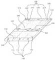
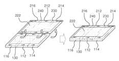
본 실시예의 접이식 휴대용 단말기는 도 1에 도시된 바와 크게 본체부(100), 표시부(200), 연결부(300)를 포함하여 구성된다.The folding portable terminal of the present embodiment includes a
상기 본체부(100)는 상호적으로 힌지연결되어 절첩가능한 복수의 본체패널(112, 114, 116)과, 각 본체패널(112, 114, 116)의 상면에 구비된 다수의 입력키(도 2의 122)를 갖는 키보드부(120)를 포함하여 이루어지고, 상기 표시부(200)는 상호적으로 힌지연결되어 절첩가능한 복수의 표시패널(212, 214, 216)과, 각 표시패널(212, 214, 216)의 상면에 전체적으로 부착되어 본체부(100)로부터 화상신호를 전달받아 화상을 출력하는 플렉시블 디스플레이(222)를 포함하여 이루어지며, 상기 연결부(300)는 본체부(100)의 전단부와 표시부(200)의 후단부를 연결하여 본체부(100)가 표시부(200)의 상면 또는 하면으로 회동가능하게 연결한다.The
먼저, 복수의 본체패널(112, 114, 116)과 다수의 입력키(도 2의 122)를 갖는 키보드부(120)가 구비된 본체부(100)에 대하여 설명하도록 한다.First, a
본체부(100)는 메인보드, 메인보드에 장착되는 CPU, 각종 데이터를 저장하는 하드디스크와 같은 저장수단, 그래픽카드, 메모리칩, 사운드를 지원하는 PCB, 통신을 하기 위한 통신모듈을 포함하여 구성된다.The
이처럼 다수의 하드웨어가 구비된 본체부(100)는, 도 1 및 도 2에 도시된 바와 같이, 상호적으로 힌지연결되어 절첩가능한 복수의 본체패널(112, 114, 116) 및 각 본체패널(112, 114, 116)의 상면에 구비된 다수의 입력키(122)로 이루어진다.As shown in FIGS. 1 and 2, the
예컨대 상기 복수의 본체패널(112, 114, 116)은, 도 2에 도시된 바와 같이, 중앙부분에 위치된 제1본체패널(112)과, 제1본체패널(112)의 상면으로 절첩가능하도록 제1본체패널(112)의 일단부에 힌지연결되는 제2본체패널(114) 및 제1본체패널(112)에 상면에 절첩된 제2본체패널(114)의 하면으로 절첩가능하도록 제1본체패널(112)의 타단부에 연결수단(130)을 개재해서 힌지연결되는 제3본체패널(116)로 구성되며, 상술한 제1, 2, 3본체패널(112, 114, 116)은 동일한 크기 및 넓이로 구성되는 것이 바람직하다.For example, as illustrated in FIG. 2, the plurality of
제1본체패널(112)의 일단부, 즉 도 2에서의 우측단부에는 다수의 힌지수 단(118)이 소정 간격으로 배열되어 구비되며, 제2본체패널(114)은 상기 다수의 힌지수단(118)을 통해 제1본체패널(112)의 우측단부에서 제1본체패널(112)의 상면으로 절첩될 수 있도록 회동하게 된다.At one end of the
상기 힌지수단(118)의 내부에는 유연한 필름선(미도시) 등이 구비되어, 제1본체패널(112)과 제2본체패널(114)을 서로 기계적으로 연결하는 것 이외에도 제1본체패널(112)과 제2본체패널(114)이 서로 전기적으로 연결될 수 있게 한다. 이러한 힌지수단(118)에 의해 제1본체패널(112)과 제2본체패널(114)이 서로 절첩되거나 펼쳐진 상태가 될 수 있음은 물론이고, 제1본체패널(112)과 제2본체패널(114)이 서로 전기적으로 연결될 수 있다.Inside the hinge means 118 is provided with a flexible film line (not shown), the
한편, 제1본체패널(112)의 타단부, 즉 도 2에서의 좌측단부에는 연결수단(130)이 구비되며, 제3본체패널(116)은 상기 연결수단(130)을 통해 제2본체패널(114)의 하면에 절첩될 수 있도록 회동하게 된다.On the other hand, the other end of the
상기 연결수단(130)은 제1본체패널(112)과 제3본체패널(116)이 서로 이격되어 위치될 수 있도록 소정의 폭을 갖도록 형성되고, 유연하게 구부러질 수 있는 소재로 이루어지는 것이 바람직하다. 이는, 제1본체패널(112)의 상면에 절첩된 제2본체패널(114)의 두께에 대응하여 제3본체패널(116)이 제2본체패널(114)의 하면에 절첩될 수 있도록 하기 위함이다.The
이러한 연결수단(130)은 상술한 힌지수단(118)과 마찬가지로 제1본체패널(112)과 제3본체패널(116)을 서로 연결하는 것 이외에도 제1본체패널(112)과 제3본체패널(116)이 서로 전기적으로 연결될 수 있게 한다.The connecting means 130, like the hinge means 118 described above, in addition to connecting the
이때, 상기 연결수단(130)의 상면에는 멤브레인(membrane) 스위치(122M)와 같이 유연하게 구부러질 수 있는 입력수단을 장착할 수 있으며, 이러한 입력수단에는 키보드부(120) 상에서 자주 사용되지 않는 F1,..., F12 키를 배정하는 것이 바람직하다.At this time, the upper surface of the connecting means 130 may be equipped with an input means that can be flexibly bent, such as a membrane switch (122M), such input means F1 which is not frequently used on the
한편, 각각의 본체패널(112, 114, 116)의 상면에는 다수의 입력키(도 2의 122)를 갖는 키보드부(120)가 구비된다.On the other hand, the upper surface of each of the
키보드부(120)에 구비된 입력키(122)는 제1, 2, 3본체패널(112, 114, 116)이 서로 절첩된 상태에서는 본체부(100)의 전체적인 두께를 최소화하기 위해 입력키(122)의 높이가 최소화되고, 제1, 2, 3본체패널(112, 114, 116)이 펼쳐친 상태에서는 사용하기 편리하도록 입력키(122)가 상방으로 탄성적으로 돌출되는 것이 바람직하다.The
예를 들면, 도 5의 (a)에 도시된 바와 같이, 제1, 2, 3본체패널(112, 114, 116)이 서로 절첩된 상태에서는 각각의 입력키(122)가 상호간의 가압에 의해 각 본체패널(112, 114, 116)의 내부로 압입되어 각 본체패널(112, 114, 116)의 표면으로부터 돌출된 입력키(122)의 높이가 1mm 내외로 낮은 상태가 되고, 도 9의 (a)에 도시된 바와 같이, 제1, 2, 3본체패널(112, 114, 116)이 펼쳐진 상태에서는 입력키(122)가 각 본체패널(112, 114, 116)의 상방측으로 탄성적 돌출되어 각 본체패널(112, 114, 116)의 표면으로부터 돌출된 입력키(122)의 높이가 5mm 내외로 높은 상태가 되도록 하는 것이다.For example, as shown in FIG. 5A, when the first, second and
일예로 도 11a에 도시된 바와 같이, 상기 입력키(122)는 키패널(122a)과, 일 단이 키패널(122a)의 하면 일측에 회전가능하게 결합되고 타단이 본체패널의 상면 일측에 슬라이딩가능하게 결합된 제1연결막대(122b)와, 일단이 키패널(122a)의 하면 타측에 슬라이딩가능하게 결합되고 타단이 본체패널의 상면 타측에 회전가능하게 결합되며 제1연결막대(122b)와 교차하여 축결합되는 제2연결막대(122c)와, 일측이 제1연결막대(122b)의 일단에 연결되고 타측이 제2연결막대(122c)의 일단에 연결되어 키패널(122a)이 상방으로 복원되게 하는 스파이럴 스프링(122d)으로 구성할 수 있다.For example, as shown in FIG. 11A, the
이때, 키패널(122a)의 하면 일측에는 제1연결막대(122b)의 일단이 회전되기 위한 제1회전몸체가 구비되고, 키패널(122a)의 하면 타측에는 제2연결막대(122c)의 일단이 슬라이딩되기 위한 제1슬라이딩몸체가 구비된다.At this time, a first rotating body for rotating one end of the first connecting
또한, 본체패널의 상면에는 제1연결막대(122b)의 타단이 슬라이딩되기 위한 제2슬라이딩몸체 및 제2연결막대(122c)의 타단이 회전되기 위한 제2회전몸체가 구비된다.In addition, an upper surface of the main body panel is provided with a second sliding body for sliding the other end of the first connecting
상술한 바와 같은 구성의 입력키(122)에 따르면, 사용자가 키패널(122a)를 하방으로 가압함에 따라 키패널이 수직하방으로 내려가게 되고, 키패널이 수직하방으로 내려감에 따라 제1연결막대(122b)와 제2연결막대(122c)의 교차점이 본체패널에 마련된 전기스위치 접촉부(122e)를 누르게 된다.According to the
한편, 키패널(122a)의 상방으로의 복원은 제1연결막대(122b)의 일단과 제2연결막대(122c)의 일단에 각각 연결된 복원스프링에 의해서, 제1연결막대(122b)의 일단과 제2연결막대(122c)의 일단이 서로 가까워지는 방향으로 당겨져서 키패 널(122a)의 상방으로의 복원이 이루어진다.On the other hand, restoring upward of the
다른 일예로 도 11b에 도시된 바와 같이, 상기 입력키(122)는 키패널(122a)과, 양단이 키패널(122a)의 하면 일측과 본체패널의 상면 일측에 각각 슬라이딩가능하게 결합된 제1연결막대(122b)와, 양단이 키패널(122a)의 하면 타측과 본체패널의 상면 타측에 각각 회전가능하게 결합되며 제1연결막대(122b)와 교차하여 축결합되는 제2연결막대(122c)와, 일측이 제1연결막대(122b)의 일단에 연결되고 타측이 제2연결막대(122c)의 일단에 연결되어 키패널(122a)이 상방으로 복원되게 하는 스파이럴 스프링(122d)으로 구성할 수 있다.As another example, as shown in FIG. 11B, the
상술한 바와 같은 구성의 입력키(122)에 따르면, 사용자가 키패널(122a)를 하방으로 가압함에 따라 키패널이 우측 하방으로 경사지게 내려가게 되고, 키패널이 우측 하방으로 경사지게 내려감에 따라 제1연결막대(122b)와 제2연결막대(122c)의 교차점이 본체패널에 마련된 전기스위치 접촉부(122e)를 누르게 된다.According to the
이처럼 키패널(122a)이 경사진 방향으로 내려가는 점을 이용하여, 키보드부의 좌측에 위치된 입력키(122)는 우측하방으로 경사지게 압입되도록 하고, 키보드부의 우측에 위치된 입력키(122)는 좌측하방으로 경사지게 압입되도록 하면, 사용자가 키보드부를 사용함에 있어 왼쪽 손과 오른쪽 손의 편의성이 증가된다는 이점이 있다.In this way, the
상술한 바와 같은 입력키(122)의 구성에 따르면, 제1, 2, 3본체패널(112, 114, 116)이 서로 절첩되어 각각의 입력키(122)(122)가 상호간의 가압의해 가압되어 각 본체패널(112, 114, 116)의 내부로 압입되고, 제1, 2, 3본체패널(112, 114, 116)이 펼쳐진 상태에서는 입력키(122)(122)가 각 본체패널(112, 114, 116)의 상방측으로 탄성적 돌출될 수 있다.According to the configuration of the
상술한 바와 같이, 제1, 2, 3본체패널(112, 114, 116)을 절첩한 상태에서는 입력키(122)의 높이가 낮아 전체적으로 두께가 얇아지므로 휴대성이 높아지고, 펼친 상태에서는 입력키(122)의 높이가 높아 사용자가 사용하기 편리하게 된다.As described above, in the folded state of the first, second and
한편, 각 본체패널(112, 114, 116)의 상면 일부에는 터치패드(122T)나 볼마우스(미도시) 등과 같이 다양한 입력장치를 설치하여 사용자로 하여금 편의성을 제공할 수 있음은 물론이다.On the other hand, a part of the upper surface of each of the main body panels (112, 114, 116) can be provided to the user by providing a variety of input devices such as a touch pad (122T) or a ball mouse (not shown).
상술한 바와 같은 본체부(100)는, 내부에 구비된 다수의 하드웨어를 통해 고속의 자동 계산, 자동제어, 데이터 처리, 사무 관리, 언어나 영상정보 처리 등 입력자료를 받아들여 처리하고 그 정보를 저장하고 검색하여 결과를 출력하며, 통신모듈을 통한 통신을 가능하게 한다.As described above, the
다음으로, 복수의 표시패널(212, 214, 216)과, 플렉시블 디스플레이(222)가 구비된 표시부(200)에 대하여 설명하도록 한다.Next, the
표시부(200)는 도 1 및 도 3에 도시된 바와 같이, 상호적으로 힌지연결되어 절첩가능한 복수의 표시패널(212, 214, 216)과, 각 표시패널(212, 214, 216)의 상면에 전체적으로 부착되어 상기 본체부(100)의 출력정보를 시각적으로 표시하는 플렉시블 디스플레이(222)를 포함하여 이루어지며, 이러한 표시부(200)는 상술한 본체부(100)가 표시부(200)의 상면 또는 하면으로 회동가능하게 연결된다.As shown in FIGS. 1 and 3, the
표시부(200)가 본체부(100)의 전단부에 양방향으로 회동가능하게 연결되는 것은 후술하게 될 연결부(300)에 의해 이루어질 수 있으며, 이 연결부(300)에 의한 본체부(100)와 표시부(200)의 연결관계에 대해서는 연결부(300)에 대한 설명시 상세하게 하도록 한다.The
한편, 도 3에 도시된 바와 같이, 상기 복수의 표시패널(212, 214, 216)은 중앙부분에 위치된 제1표시패널(212)과, 제1표시패널(212)의 상부 또는 하부로 절첩가능하도록 제1표시패널(212)의 일단부에 제1굽힘수단(230)을 개재해서 힌지연결되는 제2표시패널(214) 및 제1표시패널(212)의 상부 또는 하부에 절첩된 제2표시패널(214)의 하면 또는 상면으로 절첩가능하도록 제1표시패널(212)의 타단부에 제2굽힘수단(240)을 개재해서 힌지연결되는 제3표시패널(216)로 구성된다.As shown in FIG. 3, the plurality of
이와 같이, 제1표시패널(212), 제2표시패널(214) 및 제3표시패널(216)로 구성된 표시부(200)와 상술한 본체부(100)의 절첩관계에 대하여 설명하면 다음과 같다.As described above, the folding relationship between the
우선, 도 6a에 도시된 바와 같이, 제2본체패널(114)을 제1본체패널(112)의 상면으로 절첩시키고, 제1본체패널(112)의 상면에 절첩된 제2본체패널(114)의 하면으로 제3본체패널(116)을 절첩시켜서 본체부(100)가 전체적으로 3단절첩된 상태에서, 상기 본체부(100)가 제1표시패널(212)의 상면측으로 절첩되어 안착되도록 한다.First, as shown in FIG. 6A, the
그런 다음, 제1표시패널(212)의 일단부, 즉 도 6a에서의 우측단부에 제1굽힘수단(230)을 개재해서 연결된 제2표시패널(214)을 상기 본체부(100)의 최상면인 제3본체패널(116)의 하면으로 절첩시킨다. 이때, 상기 제1굽힘수단(230)은 소정의 폭을 갖도록 형성되고, 유연하게 구부러질 수 있는 소재로 이루어지는 것이 바람직하다. 이는, 제1표시패널(212)에 안착된 본체부(100)의 두께에 대응하여 제2표시패널(214)이 본체부(100)의 최상면에 절첩될 수 있도록 하기 위함이다.Then, the
그런 다음, 제1표시패널(212)의 타단부, 즉 도 6a에서의 좌측단부에 제2굽힘수단(240)을 개재해서 연결된 제3표시패널(216)을 상기 본체부(100)의 최상면에 절첩된 제2표시패널(214)의 하면에 절첩시킨다. 이때, 제2굽힘수단(240)은 제1굽힘수단(230)과 마찬가지로 소정의 폭을 갖도록 형성되고 유연하게 구부러질 수 있는 소재로 이루어지며, 이는, 본체부(100) 및 제2표시패널(214)의 두께에 대응하여 제2표시패널(214)의 하면에 제3표시패널(216)이 절첩될 수 있도록 하기 위함이다.Then, the
상술한 바와 같이, 표시부(200)가 3단절첩된 본체부(100)를 감싸는 구조이기 때문에, 표시부(200)의 상면에 전체적으로 부착된 플렉시블 디스플레이(222)는 최소곡률반경을 유지할 수 있으며, 이에 따라, 외부의 충격에 의해 플렉시블 디스플레이(222)가 과도하게 굽혀지거나 접혀서 발생하는 파손을 방지할 수 있게 된다.As described above, since the
한편, 본체부(100)가 제1표시패널(212)의 상면측으로 절첩되어 안착된 것에 대해 설명하였지만, 도 6b에 도시된 바와 같이, 상기 본체부(100)가 제1표시패널(212)의 하면측으로 절첩되어 안착될 수 있음은 물론이다.Meanwhile, although the
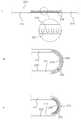
제1표시패널(212)과 제2표시패널(214)을 연결하는 제1굽힘수단(230) 및 제1표시패널(212)과 제3표시패널(216)을 연결하는 제2굽힘수단(240)의 구성은 한 쌍의 탄력성 커버부재(232)와, 이들 사이에 굽힘방향으로 배열된 다수의 쐐기형 지지 편(234)과, 다수의 쐐기형 지지편(234)의 사이마다 배열된 꽃봉오리형 탄성편(236)으로 이루어질 수 있다.First bending means 230 connecting the
즉, 금속이나 고무처럼 탄력성이 있는 한 쌍의 탄력성 커버부재(232)의 사이 내부에 삼각 형태의 쐐기형 지지편(234)이 굽힘방향으로 배열되고, 그 사이마다 꽃봉오리형 탄성편(236)가 배열되는 것이다.That is, a triangular wedge-shaped
이와 같이 구성된 제1, 2굽힘수단(230, 240)은 플렉시블 디스플레이(222)가 도 4의 (a)와 같이 굽혀지는 경우에는 꽃봉오리형 탄성편(236)이 닫히는 방향으로 복원력이 작용하여 플렉시블 디스플레이(222)가 일직선으로 복원되게 하는 힘이 작용하고, 도 4의 (b)와 같이 굽혀지는 경우에는 꽃봉오리형 탄성편(236)이 열리는 방향으로 복원력이 작용하여 플렉시블 디스플레이(222)가 일직선으로 복원되게 하는 힘이 작용하게 된다. 이때, 쐐기형 지지편(234)이나 꽃봉오리형 탄성편(236)이 없이 하나의 탄력성 커버부재(232) 또는 한 쌍의 탄력성 커버부재(232)만으로 굽힘수단을 구성할 수도 있음은 물론이다.When the
따라서 제1, 2굽힘수단(230, 240)은 아무런 외력이 없을 시 일직선 상태를 유지하고, 어느 한쪽으로 구부리는 힘이 가해지면 균등한 곡률반경으로 구부러져서 플렉시블 디스플레이(222) 화면이 균등한 곡률반경으로 구부러지게 한다.Accordingly, the first and second bending means 230 and 240 maintain a straight state when there is no external force, and when a bending force is applied to either side, the first and second bending means 230 and 240 are bent in an equal curvature radius, so that the screen of the
또한, 표시부(200)의 각 표시패널(212, 214, 216)이 절첩되어 제1, 2굽힘수단(230, 240)이 구부러지는 경우에 제1, 2굽힘수단(230, 240)에 비정상적인 외력이 가해지더라도 플렉시블 디스플레이(222)가 최소곡률반경 이하로 구부러지는 것을 방지하게 된다.In addition, when the
여기서, 표시부(200)의 절첩된 상태가 유지될 수 있도록 각 표시패널(212, 214, 216)에는 적어도 하나의 접착수단(도 1의 520)이 구비되며, 이러한 접착수단(520)으로는 막대자석을 사용할 수 있다. 이와 같은 접착수단(520)은 본체부(100)의 각 본체패널(112, 114, 116)에도 동일하게 적용될 수 있다.Here, each
한편, 제1, 2굽힘수단(230, 240)의 내부에는 유연한 필름선(미도시) 등이 구비되어, 각 표시패널(212, 214, 216) 간의 전기적인 연결이나 각 표시패널(212, 214, 216)에 구비되는 기타 장치, 예를 들면 스피커(도 1의 510), 마이크(도 1의 520)나 스크린터치를 가능하게 하는 전기적 연결 및 후술하는 평판형 추가모듈(400)에 제공되는 전기적 연결도 제공할 수 있다.On the other hand, inside the first and second bending means 230 and 240 are provided with a flexible film line (not shown), such as electrical connection between each display panel (212, 214, 216) or each display panel (212, 214) , 216, other devices, for example, a speaker (510 of FIG. 1), a microphone (520 of FIG. 1) or the electrical connection to enable the screen touch and the electrical provided to the flat
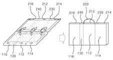
한편, 도 9에 도시된 바와 같이, 표시부(200)의 각 표시패널(212, 214, 216) 하면에는 추가모듈 장착부(250)가 구비되고, 상기 추가모듈 장착부(250)에는 평판형 추가모듈(400)이 장착될 수 있다.On the other hand, as shown in Figure 9, the lower surface of each
표시부(200)의 각 표시패널(212, 214, 216) 하면에 부착될 수 있는 평판형 추가모듈(400)로는 통신용 모듈, 추가 배터리, 디지털 카메라, 초소형 프로젝터, MP3P, 게임 모듈, 신용카드 꽂이, 돈지갑 등 다양하다. 이때, 평판형 추가모듈(400)은 표시패널의 사이즈와 동일한 것이 바람직하다.The flat panel
상술한 추가모듈 장착부(150)는 표시부(200)의 각 표시패널(212, 214, 216) 하면 이외에도 본체부(100)의 각 본체패널(112, 114, 116) 하면에도 구비될 수 있음은 물론이다.The additional module mounting unit 150 may be provided on the lower surface of each of the
상술한 바와 같은 표시부(200)는, 본체부(100)로부터 전달되는 데이터 또는 화상신호 등의 출력정보를 제공받아 사용자가 시각적으로 인식할 수 있도록 플렉시블 디스플레이(222)를 통해 화상으로 출력하게 된다.As described above, the
다음으로, 본체부(100)와 표시부(200)를 연결하는 연결부(300)에 대하여 설명하도록 한다.Next, the
상기 연결부(300)는 본체부(100)의 전단부와 표시부(200)의 후단부를 연결하여 본체부(100)가 표시부(200)의 상면 또는 하면으로 회동가능하게 연결하는 부분으로, 힌지몸체(310a, 310b) 및 이 힌지몸체(310a, 310b)로부터 신축가능하게 연장되는 가변 길이형 연결봉(320a, 320b)으로 구성된 힌지유닛(330a, 330b)으로 구성된다.The
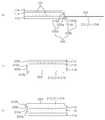
이러한 연결부(300)는, 도 5 및 도 7에 도시된 바와 같이, 하나의 힌지유닛(330a)이 본체부(100) 측에 고정설치되고, 다른 하나의 힌지유닛(330b)은 표시부(200) 측에 고정설치되어 구성될 수 있다.5 and 7, the
본체부(100) 측에 고정설치된 힌지유닛(330a)의 가변 길이형 연결봉(320a)의 일단부는 제1본체패널(112)의 상단부에 고정되고, 타단부에는 힌지몸체(310a)가 결합되며, 표시부(200) 측에 고정설치된 힌지유닛(330b)의 가변 길이형 연결봉(320b)의 일단부는 상기 본체부(100) 측에 고정설치된 힌지유닛(330a)의 힌지몸체(310a)에 회동가능하게 고정되고, 타단부에는 힌지몸체(310b)가 결합되며, 이 힌지몸체(310b)는 제1표시패널(212)의 후단부에 회동가능하게 고정된다.One end of the variable
각 힌지유닛(330a, 330b)의 힌지몸체(310a, 310b)들은 임의의 각도로 고정될 수 있도록, 단계적으로 각도가 변화할 수 있는 톱니바퀴형 클러치나 단계적으로 각도를 조정할 수 있는 각도 조정 놉(knob)으로 고정할 수 있는 구조를 갖는 것이 바람직하다.The
상술한 바와 같이 구성된 연결부(300)에 의해서, 도 5에 도시된 바와 같이, 가변 길이형 연결봉(320a , 320b)이 신장된 상태에서는 다단으로 절첩된 상태의 본체부(100)가 제1표시패널(212)의 상면 또는 하면으로 절첩될 수 있고, 도 7에 도시된 바와 같이, 가변 길이형 연결봉(320a, 320b)이 수축된 상태에서는 펼쳐진 상태의 본체부(100)가 제1표시패널(212)의 상면 또는 하면 전체에 절첩될 수 있다.As shown in FIG. 5, when the variable
도 6a에 도시된 바와 같이, 다단으로 절첩된 상태의 본체부(100)가 제1표시패널(212)의 상면으로 절첩된 경우에는 제3본체패널(116)의 하면에 휴대폰 키(a) 및 소형 디스플레이 창(b)을 구비하여 접이식 휴대용 단말기를 펼치지 않고도 휴대폰과 같이 통화를 할 수 있게 하며, 도 6b에 도시된 바와 같이, 다단으로 절첩된 상태의 본체부(100)가 제1표시패널(212)의 하면으로 절첩된 경우에는 제1표시패널(212) 부분의 플렉시블 디스플레이(222)만 작동하도록 하여 이동 중에 좁은 화면의 영상을 볼 수 있게 한다.As shown in FIG. 6A, when the
또한, 도 8a에 도시된 바와 같이, 펼쳐진 상태의 본체부(100)가 제1표시패널(212)의 상면 전체에 절첩된 경우에는 접이식 휴대용 단말기를 노트북처럼 펼쳐서 사용하다가 노트북처럼 접어서 휴대할 수 있으므로 노트북 형태로 자주 접었다 펴서 사용하는 경우에 편리하여 접이식 휴대용 단말기를 노트북처럼 사용할 수 있고, 도 8b에 도시된 바와 같이, 펼쳐진 상태의 본체부(100)가 제1표시패널(212)의 하면 전체에 절첩된 경우에는 접이식 휴대용 단말기의 넓은 화면만 필요로 하는 경우에 편리하게 사용할 수 있다.In addition, as shown in FIG. 8A, when the
한편, 도 8a에서와 같이 접이식 휴대용 단말기를 노트북처럼 사용하는 경우에 착탈식 손잡이(202)를 구비하여 사용자가 손으로 잡고 휴대하거나 이동할 수 있도록 하는 것이 바람직하다.On the other hand, when using a folding portable terminal as shown in Figure 8a as a notebook, it is preferable to have a
상술한 연결부(300)는 본체부(100)와 표시부(200)를 기계적으로 연결하는 것뿐만 아니라 본체부(100)와 표시부(200) 간의 전기적인 연결을 가능하게 하는 고유연성 필름선(미도시) 등이 구비되어 본체부(100)의 화상신호가 표시부(200)로 전달되어 출력될 수 있도록 한다.The
상기에 설명한 접이식 휴대용 단말기는 본체부(100)와 표시부(200) 모두 3단으로 절첩되는 구조로 설명하였지만,Although the above-described foldable portable terminal has been described in a structure in which both the
제1'본체패널(112') 및 상기 제1'본체패널(112')의 상면으로 절첩가능하도록 제1'본체패널(112')의 일단부에 힌지연결되는 제2'본체패널(114')로 이루어진 본체부(100')와, 제1'표시패널(212') 및 상기 제1'표시패널(212')의 상부 또는 하부로 절첩가능하도록 제1'표시패널(212')의 일단부에 제1'굽힘수단(230')을 개재해서 힌지연결되는 제2'표시패널(214')로 이루어진 표시부(200')로 구성되어 본체부(100')와 표시부(200')가 각 2단으로 절첩되는 구조로 구성될 수 있음은 물론이고, 본체부와 표시부가 서로 다른 갯수로 나누어져 절첩되는 구조로 구성될 수 있음은 물론이다.A second 'body panel 114' hingedly connected to one end of the first 'body panel 112' to be foldable to the first surface of the first body panel 112 'and the first body panel 112'. One end of the first 'display panel 212' so as to be foldable up or down of the main body portion 100 'and the first' display panel 212 'and the first' display panel 212 '. Is composed of a display portion 200 'consisting of a second display panel 214' hinged via a first 'bending means 230' to the body portion 100 'and the display portion 200'. Of course, it can be configured as a structure that is folded in two stages, of course, the body portion and the display portion can be configured to be folded into a different number of different structures.
이상에서 본 발명의 실시예에 대하여 상세하게 설명하였지만 본 발명의 권리 범위는 이에 한정되는 것은 아니고 다음의 청구범위에서 정의하고 있는 본 발명의 기본 개념을 이용한 당업자의 여러 변형 및 개량 형태 또한 본 발명의 권리범위에 속하는 것이다.Although the embodiments of the present invention have been described in detail above, the scope of the present invention is not limited thereto, and various modifications and improvements of those skilled in the art using the basic concepts of the present invention defined in the following claims are also provided. It belongs to the scope of rights.
도 1은 본 발명의 실시예에 따른 접이식 휴대용 단말기의 펼친 상태를 나타내는 사시도.1 is a perspective view showing an unfolded state of a foldable portable terminal according to an embodiment of the present invention.
도 2는 본 발명의 실시예에 따른 접이식 휴대용 단말기의 본체부를 나타내는 평면도.2 is a plan view showing a main body of a foldable portable terminal according to an embodiment of the present invention.
도 3은 본 발명의 실시예에 따른 접이식 휴대용 단말기의 표시부를 나타내는 평면도.3 is a plan view showing a display unit of a foldable portable terminal according to an embodiment of the present invention.
도 4는 본 발명의 실시예에 따른 접이식 휴대용 단말기의 굽힘수단을 나타내는 개략도.Figure 4 is a schematic diagram showing the bending means of the foldable portable terminal according to an embodiment of the present invention.
도 5는 본 발명의 실시예에 따른 접이식 휴대용 단말기의 접힘 상태를 나타내는 개략도.5 is a schematic view showing a folded state of a foldable portable terminal according to an embodiment of the present invention.
도 6a 및 도 6b는 본 발명의 실시예에 따른 접이식 휴대용 단말기의 접힘 상태를 나타내는 사시도.6A and 6B are perspective views illustrating a folded state of a foldable portable terminal according to an embodiment of the present invention.
도 7은 본 발명의 실시예에 따른 접이식 휴대용 단말기의 접힘 상태를 나타내는 개략도.7 is a schematic diagram showing a folded state of a foldable portable terminal according to an embodiment of the present invention.
도 8a 및 도 8b는 본 발명의 실시예에 따른 접이식 휴대용 단말기의 접힘 상태를 나타내는 사시도.8A and 8B are perspective views illustrating a folded state of a foldable portable terminal according to an embodiment of the present invention.
도 9는 본 발명의 실시예에 따른 접이식 휴대용 단말기에 평판형 추가모듈이 장착된 것을 나타내는 사시도.Figure 9 is a perspective view showing that the flat additional module is mounted on the folding portable terminal according to an embodiment of the present invention.
도 10은 본 발명의 다른 실시예에 따른 접이식 휴대용 단말기의 접힘 상태를 나타내는 사시도.10 is a perspective view showing a folded state of a foldable portable terminal according to another embodiment of the present invention.
도 11a 및 도 11b는 본 발명의 다른 실시예에 따른 접이식 휴대용 단말기의 입력키의 작동 상태를 나타내는 개략도.11A and 11B are schematic views showing an operating state of an input key of a foldable portable terminal according to another embodiment of the present invention.
<도면의 주요 부분에 대한 부호의 설명><Explanation of symbols for the main parts of the drawings>
100:본체부112:제1본체패널100: main body 112: first body panel
114:제2본체패널116:제3본체패널114: second body panel 116: third body panel
122:입력키130:연결수단122: input key 130: connection means
150:추가모듈 장착부200:표시부150: additional module mounting part 200: display part
212:제1표시패널214:제2표시패널212: first display panel 214: second display panel
216:제3표시패널222:플렉시블 디스플레이216: third display panel 222: flexible display
230:제1굽힘수단232:탄력성 커버부재230: first bending means 232: elastic cover member
234:쐐기형 지지편236:꽃봉오리형 탄성편234: wedge type support piece 236: bud type elastic piece
240:제2굽힘수단300:연결부240: second bending means 300: connection portion
310a, 310b:힌지몸체320a, 320b:가변 길이형 연결봉310a, 310b:
330a, 330b:힌지유닛400:평판형 추가모듈330a, 330b: Hinge unit 400: Flat additional module
Claims (12)
Translated fromKoreanPriority Applications (1)
| Application Number | Priority Date | Filing Date | Title |
|---|---|---|---|
| KR1020070083754AKR100867608B1 (en) | 2007-08-21 | 2007-08-21 | Foldable handheld terminal |
Applications Claiming Priority (1)
| Application Number | Priority Date | Filing Date | Title |
|---|---|---|---|
| KR1020070083754AKR100867608B1 (en) | 2007-08-21 | 2007-08-21 | Foldable handheld terminal |
Publications (1)
| Publication Number | Publication Date |
|---|---|
| KR100867608B1true KR100867608B1 (en) | 2008-11-10 |
Family
ID=40283837
Family Applications (1)
| Application Number | Title | Priority Date | Filing Date |
|---|---|---|---|
| KR1020070083754AExpired - Fee RelatedKR100867608B1 (en) | 2007-08-21 | 2007-08-21 | Foldable handheld terminal |
Country Status (1)
| Country | Link |
|---|---|
| KR (1) | KR100867608B1 (en) |
Cited By (20)
| Publication number | Priority date | Publication date | Assignee | Title |
|---|---|---|---|---|
| CN102262845A (en)* | 2010-05-31 | 2011-11-30 | 纬创资通股份有限公司 | Electronic device that provides planar support for a display panel |
| WO2012167204A2 (en) | 2011-06-03 | 2012-12-06 | Microsoft Corporation | Flexible display flexure assembly |
| KR20130057029A (en)* | 2011-11-23 | 2013-05-31 | 삼성전자주식회사 | Display device and control method thereof |
| KR20150024172A (en)* | 2013-08-26 | 2015-03-06 | 삼성전자주식회사 | foldable electronic device having flexible display |
| EP2960747A3 (en)* | 2014-06-24 | 2016-04-27 | Samsung Electronics Co., Ltd | Flexible device and folding unit thereof |
| US9470404B2 (en) | 2014-05-13 | 2016-10-18 | Samsung Display Co., Ltd. | Foldable display apparatus |
| US9798359B2 (en) | 2014-02-21 | 2017-10-24 | Samsung Electronics Co., Ltd. | Foldable device |
| EP3258675A1 (en)* | 2016-06-15 | 2017-12-20 | LG Electronics Inc. | Mobile terminal |
| KR101831175B1 (en) | 2009-04-22 | 2018-02-26 | 삼성전자주식회사 | An electronic apparatus with a flexible display having a body enabling further functionality |
| KR101857062B1 (en) | 2014-07-31 | 2018-05-11 | 삼성전자주식회사 | Flexible device and method for performing interfacing thereof |
| WO2018194605A1 (en)* | 2017-04-20 | 2018-10-25 | Hewlett-Packard Development Company, L.P. | Foldable hinge for electronic devices |
| KR20190033647A (en)* | 2011-09-30 | 2019-03-29 | 애플 인크. | Flexible electronic devices |
| JP2020013163A (en)* | 2013-08-20 | 2020-01-23 | 株式会社半導体エネルギー研究所 | Display device |
| WO2020055203A1 (en)* | 2018-09-13 | 2020-03-19 | 오준수 | Foldable multimedia terminal |
| KR20200067804A (en)* | 2019-06-25 | 2020-06-12 | 삼성전자주식회사 | foldable electronic device having flexible display |
| US11068074B2 (en) | 2014-07-31 | 2021-07-20 | Samsung Electronics Co., Ltd. | Flexible device and interfacing method thereof |
| WO2022010195A1 (en)* | 2020-07-08 | 2022-01-13 | 삼성전자 주식회사 | Multi-foldable electronic device |
| JP2022028707A (en)* | 2019-09-17 | 2022-02-16 | 株式会社半導体エネルギー研究所 | Display |
| US11675394B2 (en) | 2017-12-28 | 2023-06-13 | Samsung Display Co., Ltd. | Display device |
| US12153472B2 (en) | 2014-02-21 | 2024-11-26 | Samsung Electronics Co., Ltd. | Foldable device |
Citations (2)
| Publication number | Priority date | Publication date | Assignee | Title |
|---|---|---|---|---|
| KR20010106091A (en)* | 1999-12-17 | 2001-11-29 | 이케다 데루타카 | Keyboard switch |
| JP2004109382A (en)* | 2002-09-17 | 2004-04-08 | Brother Ind Ltd | Foldable display, input device with foldable display and keyboard, and personal computer with the input device |
- 2007
- 2007-08-21KRKR1020070083754Apatent/KR100867608B1/ennot_activeExpired - Fee Related
Patent Citations (2)
| Publication number | Priority date | Publication date | Assignee | Title |
|---|---|---|---|---|
| KR20010106091A (en)* | 1999-12-17 | 2001-11-29 | 이케다 데루타카 | Keyboard switch |
| JP2004109382A (en)* | 2002-09-17 | 2004-04-08 | Brother Ind Ltd | Foldable display, input device with foldable display and keyboard, and personal computer with the input device |
Cited By (59)
| Publication number | Priority date | Publication date | Assignee | Title |
|---|---|---|---|---|
| KR101831175B1 (en) | 2009-04-22 | 2018-02-26 | 삼성전자주식회사 | An electronic apparatus with a flexible display having a body enabling further functionality |
| CN102262845A (en)* | 2010-05-31 | 2011-11-30 | 纬创资通股份有限公司 | Electronic device that provides planar support for a display panel |
| EP2715477A4 (en)* | 2011-06-03 | 2015-03-11 | Microsoft Corp | Flexible display flexure assembly |
| CN103620516A (en)* | 2011-06-03 | 2014-03-05 | 微软公司 | Flexible display flexure assembly |
| KR20140026547A (en)* | 2011-06-03 | 2014-03-05 | 마이크로소프트 코포레이션 | Flexible display flexure assembly |
| KR101955050B1 (en)* | 2011-06-03 | 2019-03-06 | 마이크로소프트 테크놀로지 라이센싱, 엘엘씨 | Flexible display flexure assembly |
| US9176535B2 (en) | 2011-06-03 | 2015-11-03 | Microsoft Technology Licensing, Llc | Flexible display flexure assembly |
| RU2596469C2 (en)* | 2011-06-03 | 2016-09-10 | МАЙКРОСОФТ ТЕКНОЛОДЖИ ЛАЙСЕНСИНГ, ЭлЭлСи | Flexible assembly of flexible display |
| TWI566214B (en)* | 2011-06-03 | 2017-01-11 | 微軟技術授權有限責任公司 | Flexible display flexure assembly |
| WO2012167204A2 (en) | 2011-06-03 | 2012-12-06 | Microsoft Corporation | Flexible display flexure assembly |
| US11675390B2 (en) | 2011-09-30 | 2023-06-13 | Apple Inc. | Flexible electronic devices |
| US10739908B2 (en) | 2011-09-30 | 2020-08-11 | Apple Inc. | Flexible electronic devices |
| KR20190033647A (en)* | 2011-09-30 | 2019-03-29 | 애플 인크. | Flexible electronic devices |
| US11994906B2 (en) | 2011-09-30 | 2024-05-28 | Apple Inc. | Flexible electronic devices |
| KR102151778B1 (en)* | 2011-09-30 | 2020-09-04 | 애플 인크. | Flexible electronic devices |
| KR101879615B1 (en)* | 2011-11-23 | 2018-07-19 | 삼성전자주식회사 | Display device and control method thereof |
| KR20130057029A (en)* | 2011-11-23 | 2013-05-31 | 삼성전자주식회사 | Display device and control method thereof |
| JP2020013163A (en)* | 2013-08-20 | 2020-01-23 | 株式会社半導体エネルギー研究所 | Display device |
| EP4170463A1 (en)* | 2013-08-26 | 2023-04-26 | Samsung Electronics Co., Ltd. | Foldable electronic device including flexible display element |
| CN108628406B (en)* | 2013-08-26 | 2021-09-03 | 三星电子株式会社 | Foldable electronic device comprising a flexible display element |
| US9811119B2 (en) | 2013-08-26 | 2017-11-07 | Samsung Electronics Co., Ltd. | Foldable electronic device including flexible display element |
| US11048302B2 (en) | 2013-08-26 | 2021-06-29 | Samsung Electronics Co., Ltd. | Foldable electronic device including flexible display element |
| US11726528B2 (en) | 2013-08-26 | 2023-08-15 | Samsung Electronics Co., Ltd. | Foldable electronic device including flexible display element |
| KR101663728B1 (en)* | 2013-08-26 | 2016-10-07 | 삼성전자주식회사 | foldable electronic device having flexible display |
| EP3693832A1 (en)* | 2013-08-26 | 2020-08-12 | Samsung Electronics Co., Ltd. | Foldable electronic device including flexible display element |
| CN108628406A (en)* | 2013-08-26 | 2018-10-09 | 三星电子株式会社 | Foldable electronic device including flexible display element |
| US12204375B2 (en) | 2013-08-26 | 2025-01-21 | Samsung Electronics Co., Ltd. | Foldable electronic device including flexible display element |
| KR20150024172A (en)* | 2013-08-26 | 2015-03-06 | 삼성전자주식회사 | foldable electronic device having flexible display |
| US10423196B2 (en) | 2014-02-21 | 2019-09-24 | Samsung Electronics Co., Ltd. | Foldable device |
| US10120415B2 (en) | 2014-02-21 | 2018-11-06 | Samsung Electronics Co., Ltd. | Foldable device |
| US12153472B2 (en) | 2014-02-21 | 2024-11-26 | Samsung Electronics Co., Ltd. | Foldable device |
| US9798359B2 (en) | 2014-02-21 | 2017-10-24 | Samsung Electronics Co., Ltd. | Foldable device |
| US10901464B2 (en) | 2014-02-21 | 2021-01-26 | Samsung Electronics Co., Ltd. | Foldable device |
| US11567540B2 (en) | 2014-02-21 | 2023-01-31 | Samsung Electronics Co., Ltd. | Foldable device |
| US9470404B2 (en) | 2014-05-13 | 2016-10-18 | Samsung Display Co., Ltd. | Foldable display apparatus |
| EP2960747A3 (en)* | 2014-06-24 | 2016-04-27 | Samsung Electronics Co., Ltd | Flexible device and folding unit thereof |
| US9823699B2 (en) | 2014-06-24 | 2017-11-21 | Samsung Electronics Co., Ltd. | Flexible device and folding unit thereof |
| US11068074B2 (en) | 2014-07-31 | 2021-07-20 | Samsung Electronics Co., Ltd. | Flexible device and interfacing method thereof |
| KR20180050631A (en)* | 2014-07-31 | 2018-05-15 | 삼성전자주식회사 | Flexible device and method for performing interfacing thereof |
| KR101857062B1 (en) | 2014-07-31 | 2018-05-11 | 삼성전자주식회사 | Flexible device and method for performing interfacing thereof |
| KR102271289B1 (en) | 2014-07-31 | 2021-07-01 | 삼성전자주식회사 | Flexible device and method for performing interfacing thereof |
| EP3258675A1 (en)* | 2016-06-15 | 2017-12-20 | LG Electronics Inc. | Mobile terminal |
| CN107526395A (en)* | 2016-06-15 | 2017-12-29 | Lg 电子株式会社 | Mobile terminal |
| US10061358B2 (en) | 2016-06-15 | 2018-08-28 | Lg Electronics | Mobile terminal |
| US11553612B2 (en) | 2017-04-20 | 2023-01-10 | Hewlett-Packard Development Company, L.P. | Foldable hinge for electronic devices |
| WO2018194605A1 (en)* | 2017-04-20 | 2018-10-25 | Hewlett-Packard Development Company, L.P. | Foldable hinge for electronic devices |
| CN110178452A (en)* | 2017-04-20 | 2019-08-27 | 惠普发展公司,有限责任合伙企业 | Foldable hinge for electronic equipment |
| US11675394B2 (en) | 2017-12-28 | 2023-06-13 | Samsung Display Co., Ltd. | Display device |
| US11836011B2 (en) | 2018-09-13 | 2023-12-05 | June Soo Oh | Foldable multimedia terminal |
| WO2020055203A1 (en)* | 2018-09-13 | 2020-03-19 | 오준수 | Foldable multimedia terminal |
| KR102273675B1 (en)* | 2019-06-25 | 2021-07-07 | 삼성전자주식회사 | foldable electronic device having flexible display |
| KR20200067804A (en)* | 2019-06-25 | 2020-06-12 | 삼성전자주식회사 | foldable electronic device having flexible display |
| JP7143499B2 (en) | 2019-09-17 | 2022-09-28 | 株式会社半導体エネルギー研究所 | Display device |
| JP2022028707A (en)* | 2019-09-17 | 2022-02-16 | 株式会社半導体エネルギー研究所 | Display |
| KR20210084393A (en)* | 2020-06-04 | 2021-07-07 | 삼성전자주식회사 | foldable electronic device having flexible display |
| KR102345995B1 (en) | 2020-06-04 | 2022-01-03 | 삼성전자주식회사 | foldable electronic device having flexible display |
| KR20220006213A (en)* | 2020-07-08 | 2022-01-17 | 삼성전자주식회사 | Multi foldable electronic device |
| WO2022010195A1 (en)* | 2020-07-08 | 2022-01-13 | 삼성전자 주식회사 | Multi-foldable electronic device |
| KR102732900B1 (en) | 2020-07-08 | 2024-11-22 | 삼성전자주식회사 | Multi foldable electronic device |
Similar Documents
| Publication | Publication Date | Title |
|---|---|---|
| KR100867608B1 (en) | Foldable handheld terminal | |
| EP0932861B1 (en) | Hand-held computer and communications apparatus | |
| US7253802B2 (en) | User interface | |
| CN105830140B (en) | folding device | |
| CN101388918B (en) | Electronic equipment | |
| EP1578089B1 (en) | A hinge mechanism for a portable, foldable electronic device compirising at least two use positions | |
| US7522944B2 (en) | Portable communication apparatus | |
| JP5574680B2 (en) | Portable display device | |
| KR20040021366A (en) | Portable information phone with expansion data inputting unit | |
| JP2018519716A (en) | Unlocking device for portable terminal and portable terminal | |
| CN111107189A (en) | Rotating shaft mechanism and electronic equipment | |
| US8082631B2 (en) | Folding mechanism for compact device | |
| JP2004109382A (en) | Foldable display, input device with foldable display and keyboard, and personal computer with the input device | |
| EP2746894A2 (en) | Flexible apparatus structure | |
| JP2004118803A (en) | Input device with foldable display and keyboard, and personal computer with the input device | |
| KR20170142597A (en) | Flexible display module and one side folding apparatus with it | |
| TWI612870B (en) | Protective case with keyboard and combination of protective case and electronic device | |
| JP2005141715A (en) | Portable terminal device | |
| KR100378120B1 (en) | Folder type mobile phone | |
| KR100796944B1 (en) | Elastic module using an integrated spring wound in both directions in a winding shape and a slide device of a sliding type mobile phone having the same | |
| JP2004110305A (en) | Input device with foldable display and keyboard, and personal computer with the input device | |
| KR101117783B1 (en) | Mobile communication terminal with keys increased | |
| JP2004110303A (en) | Input device with foldable display and keyboard, and personal computer with the input device | |
| CN120045026A (en) | Protective sleeve of flat-plate type electronic equipment | |
| JP2004110304A (en) | Input device with foldable display and keyboard, and personal computer with the input device |
Legal Events
| Date | Code | Title | Description |
|---|---|---|---|
| A201 | Request for examination | ||
| PA0109 | Patent application | St.27 status event code:A-0-1-A10-A12-nap-PA0109 | |
| PA0201 | Request for examination | St.27 status event code:A-1-2-D10-D11-exm-PA0201 | |
| D13-X000 | Search requested | St.27 status event code:A-1-2-D10-D13-srh-X000 | |
| D14-X000 | Search report completed | St.27 status event code:A-1-2-D10-D14-srh-X000 | |
| E902 | Notification of reason for refusal | ||
| PE0902 | Notice of grounds for rejection | St.27 status event code:A-1-2-D10-D21-exm-PE0902 | |
| E13-X000 | Pre-grant limitation requested | St.27 status event code:A-2-3-E10-E13-lim-X000 | |
| P11-X000 | Amendment of application requested | St.27 status event code:A-2-2-P10-P11-nap-X000 | |
| P13-X000 | Application amended | St.27 status event code:A-2-2-P10-P13-nap-X000 | |
| E701 | Decision to grant or registration of patent right | ||
| PE0701 | Decision of registration | St.27 status event code:A-1-2-D10-D22-exm-PE0701 | |
| GRNT | Written decision to grant | ||
| PR0701 | Registration of establishment | St.27 status event code:A-2-4-F10-F11-exm-PR0701 | |
| PR1002 | Payment of registration fee | St.27 status event code:A-2-2-U10-U11-oth-PR1002 Fee payment year number:1 | |
| PG1601 | Publication of registration | St.27 status event code:A-4-4-Q10-Q13-nap-PG1601 | |
| FPAY | Annual fee payment | Payment date:20111102 Year of fee payment:4 | |
| PR1001 | Payment of annual fee | St.27 status event code:A-4-4-U10-U11-oth-PR1001 Fee payment year number:4 | |
| FPAY | Annual fee payment | Payment date:20121031 Year of fee payment:5 | |
| PR1001 | Payment of annual fee | St.27 status event code:A-4-4-U10-U11-oth-PR1001 Fee payment year number:5 | |
| R18-X000 | Changes to party contact information recorded | St.27 status event code:A-5-5-R10-R18-oth-X000 | |
| LAPS | Lapse due to unpaid annual fee | ||
| PC1903 | Unpaid annual fee | St.27 status event code:A-4-4-U10-U13-oth-PC1903 Not in force date:20131104 Payment event data comment text:Termination Category : DEFAULT_OF_REGISTRATION_FEE | |
| PC1903 | Unpaid annual fee | St.27 status event code:N-4-6-H10-H13-oth-PC1903 Ip right cessation event data comment text:Termination Category : DEFAULT_OF_REGISTRATION_FEE Not in force date:20131104 | |
| PN2301 | Change of applicant | St.27 status event code:A-5-5-R10-R13-asn-PN2301 St.27 status event code:A-5-5-R10-R11-asn-PN2301 | |
| R18-X000 | Changes to party contact information recorded | St.27 status event code:A-5-5-R10-R18-oth-X000 | |
| R18-X000 | Changes to party contact information recorded | St.27 status event code:A-5-5-R10-R18-oth-X000 | |
| R18-X000 | Changes to party contact information recorded | St.27 status event code:A-5-5-R10-R18-oth-X000 |