KR100866380B1 - Estimation method of robot's magnetic position based on object recognition - Google Patents
Estimation method of robot's magnetic position based on object recognitionDownload PDFInfo
- Publication number
- KR100866380B1 KR100866380B1KR1020070015026AKR20070015026AKR100866380B1KR 100866380 B1KR100866380 B1KR 100866380B1KR 1020070015026 AKR1020070015026 AKR 1020070015026AKR 20070015026 AKR20070015026 AKR 20070015026AKR 100866380 B1KR100866380 B1KR 100866380B1
- Authority
- KR
- South Korea
- Prior art keywords
- robot
- node
- equation
- estimating
- candidate node
- Prior art date
- Legal status (The legal status is an assumption and is not a legal conclusion. Google has not performed a legal analysis and makes no representation as to the accuracy of the status listed.)
- Expired - Fee Related
Links
Images


Classifications
- B—PERFORMING OPERATIONS; TRANSPORTING
- B25—HAND TOOLS; PORTABLE POWER-DRIVEN TOOLS; MANIPULATORS
- B25J—MANIPULATORS; CHAMBERS PROVIDED WITH MANIPULATION DEVICES
- B25J13/00—Controls for manipulators
- B25J13/08—Controls for manipulators by means of sensing devices, e.g. viewing or touching devices
- B25J13/088—Controls for manipulators by means of sensing devices, e.g. viewing or touching devices with position, velocity or acceleration sensors
- B—PERFORMING OPERATIONS; TRANSPORTING
- B25—HAND TOOLS; PORTABLE POWER-DRIVEN TOOLS; MANIPULATORS
- B25J—MANIPULATORS; CHAMBERS PROVIDED WITH MANIPULATION DEVICES
- B25J19/00—Accessories fitted to manipulators, e.g. for monitoring, for viewing; Safety devices combined with or specially adapted for use in connection with manipulators
- B25J19/02—Sensing devices
- B25J19/021—Optical sensing devices
- B25J19/023—Optical sensing devices including video camera means
- G—PHYSICS
- G05—CONTROLLING; REGULATING
- G05D—SYSTEMS FOR CONTROLLING OR REGULATING NON-ELECTRIC VARIABLES
- G05D1/00—Control of position, course, altitude or attitude of land, water, air or space vehicles, e.g. using automatic pilots
- G05D1/20—Control system inputs
- G05D1/24—Arrangements for determining position or orientation
- G05D1/243—Means capturing signals occurring naturally from the environment, e.g. ambient optical, acoustic, gravitational or magnetic signals
- G—PHYSICS
- G05—CONTROLLING; REGULATING
- G05D—SYSTEMS FOR CONTROLLING OR REGULATING NON-ELECTRIC VARIABLES
- G05D1/00—Control of position, course, altitude or attitude of land, water, air or space vehicles, e.g. using automatic pilots
- G05D1/20—Control system inputs
- G05D1/24—Arrangements for determining position or orientation
- G05D1/246—Arrangements for determining position or orientation using environment maps, e.g. simultaneous localisation and mapping [SLAM]
Landscapes
- Engineering & Computer Science (AREA)
- Aviation & Aerospace Engineering (AREA)
- Radar, Positioning & Navigation (AREA)
- Remote Sensing (AREA)
- Physics & Mathematics (AREA)
- General Physics & Mathematics (AREA)
- Automation & Control Theory (AREA)
- Robotics (AREA)
- Mechanical Engineering (AREA)
- Multimedia (AREA)
- Human Computer Interaction (AREA)
- Manipulator (AREA)
Abstract
Translated fromKoreanDescription
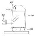
Translated fromKorean도1은 본 발명에 따른 물체인식을 바탕으로 자기위치를 추정하는 로봇의 구조도이다.1 is a structural diagram of a robot for estimating a magnetic position based on object recognition according to the present invention.
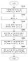
도2는 본 발명에 따른 물체인식을 바탕으로 한 로봇의 자기위치 추정 방법의 기본 순서도이다.2 is a basic flowchart of a method for estimating a magnetic position of a robot based on object recognition according to the present invention.
도3은 본 발명에 따른 로봇 중심의 물체 인식 및 물체 위치 개념도이다.3 is a conceptual view of robot-centered object recognition and object position according to the present invention.
도4는 본 발명에 따른 환경 중심의 물체 위치 개념도이다.4 is a conceptual diagram of an object-centered object position according to the present invention.
도5는 본 발명에 따른 로봇 중심의 물체 위치와 환경 중심의 물체 위치간의 관계도이다.5 is a relationship diagram between the object position in the robot center and the object position in the environment according to the present invention.
도6은 본 발명에 따른 물체인식을 바탕으로 한 로봇의 자기위치 추정 방법에서 사용되는 위상학적 지도의 예시도이다.6 is an exemplary diagram of a topological map used in a method for estimating a magnetic position of a robot based on object recognition according to the present invention.
도7은 파티클 필터링에 기반한 위치 추정 방법의 순서도이다.7 is a flowchart of a position estimation method based on particle filtering.
도8은 본 발명의 제1 실시예에 따른 물체인식을 바탕으로 한 로봇의 자기위치 추정 방법의 순서도이다.8 is a flowchart of a method for estimating a magnetic position of a robot based on object recognition according to the first embodiment of the present invention.
도9는 본 발명의 제2 실시예에 따른 물체인식을 바탕으로 한 로봇의 자기위치 추정 방법의 순서도이다.9 is a flowchart of a method for estimating a magnetic position of a robot based on object recognition according to a second embodiment of the present invention.
도10은 본 발명의 제3 실시예에 따른 물체인식을 바탕으로 한 로봇의 자기위치 추정 방법의 순서도이다.10 is a flowchart of a method for estimating a magnetic position of a robot based on object recognition according to a third embodiment of the present invention.
본 발명은 이동 로봇이 기준좌표가 주어진 동작 환경내에서 로봇 스스로 자기의 위치를 추정(estimation)하는 방법에 관한 것으로, 이동 로봇이 환경내의 개별 물체들을 비전 센서에 의해 인식을 하고 주어진 지도(맵)를 기반으로 센서의 입력을 분석하여 자기의 위치를 추정(estimation)하는 방법에 대한 발명이다.The present invention relates to a method in which a mobile robot estimates its own position in an operating environment given a reference coordinate. The mobile robot recognizes individual objects in the environment by a vision sensor and provides a map. The present invention relates to a method of estimating a magnetic position by analyzing a sensor input based on the method.
산업용 로봇에서 시작한 로봇은 최근에는 임의의 환경에서도 동작할 수 있는 지능로봇의 형태로 그 응용 영역을 넓혀가고 있다. 이러한 지능로봇은 청소로봇을 비롯하여, 경비로봇, 위험물 탐지 로봇, 가사 도우미 로봇 및 교육 로봇등이 있을 수가 있다. 이러한 로봇이 주어진 환경에서 사람에게 서비스를 제공하기 위해서는 로봇 주행기술의 확보는 필수적이며, 그 중에서 로봇이 자기 위치를 추정해야 하는 자기위치추정(self-localization) 기술은 핵심적 요소 기술이 된다.Robots, starting with industrial robots, have recently been expanding their applications in the form of intelligent robots that can operate in any environment. Such intelligent robots may include cleaning robots, security robots, dangerous goods detection robots, housework helper robots, and educational robots. In order to provide services to people in a given environment, it is essential to secure robot driving technology. Among them, self-localization technology, which requires the robot to estimate its position, becomes a key element technology.
이러한 로봇의 자기 위치 추정 기술은 기본적으로 지도를 바탕으로 이루어지기 때문에 로봇이 이용하는 지도 표상(representation)이 어떤 방식으로 구성되어져 있느냐와 이용하는 센서에 따라 다양하게 변화할 수 있다. 최근의 기술의 전개는 지도(맵)는 통상 격자지도와 같은 수치적 지도위에 위상적(topological) 지도를 결합하여 사용을 하며, 센서로는 레이저 및 초음파센서에서 비전 센서로 발전을 이 루고 있는데, 이는 비전 센서가 거리 정보뿐만 아니라 영상에 기반하여 색상, 물체식별 및 사람식별등과 같은 풍부한 추가 정보를 제공할 수도 있어 그 사용의 확대가 이루어지고 있다.Since the robot's self-positioning technique is basically based on a map, it can be variously changed depending on how the map representation used by the robot is configured and the sensor used. Recent developments in maps use topographic maps on top of numerical maps, such as grid maps, which are being developed from laser and ultrasonic sensors to vision sensors. This is because the vision sensor can provide abundant additional information such as color, object identification and person identification based on the image as well as the distance information.
이러한 비전 센서를 기반으로 물체 인식 기술을 바탕으로 하여 로봇의 자기 위치를 추정(estimation)하고자 한 종래의 기술은 다음과 같다.Conventional techniques for estimating the magnetic position of a robot based on an object recognition technology based on such a vision sensor are as follows.
국내의 특허로는 물체에 액티브태그를 붙여 이를 비전 센서로 인식하고 이를 물체와 로봇 사이의 위치를 알고자 한 특허(공개번호 10-2006-0102389)와 비전기반의 이동로봇의 위치 제어 시스템 특허(공개 번호 10-2005-0062713)가 있다. 전자는 로봇이 이동하는 경로에 있는 물체에 인공적 태그를 부착하여야 하는 불편함이 있으며, 후자는 비전 센서가 로봇에 부착되지 아니하고 환경에 부착되어 단순히 로봇만을 인식하여 그 위치를 추정하는 방식이어서 환경에 따라 비전 센서가 필요하므로 다수의 비전 센서를 설치해야 한다는 단점이 있었다.Domestic patents include active tags attached to objects to recognize them as vision sensors and know the location between objects and robots (Publication No. 10-2006-0102389) and patents for position control systems of vision-based mobile robots. Publication No. 10-2005-0062713. The former is inconvenient to attach an artificial tag to an object in the path that the robot moves, and the latter is a method of estimating its position by simply recognizing the robot by attaching it to the environment instead of attaching it to the robot. As a result, a vision sensor is required, which requires the installation of multiple vision sensors.
외국의 특허로는 미국의 비전 센서에 의해 자기위치 추정과 맵 구현을 동시에 수행하는 특허(미국 특허 US 7015831) 기술이 대표적이다. 그러나, 이 특허의 기술도 환경에서 비전 센서를 이용하여 물체 단위로 인식을 수행하지 아니하고 3차원상의 국소적 특징점들을 추출하여 이를 바탕으로 자기위치를 추정함으로써 향후 환경 변화의 요인에 대처할 수 있는 수단을 상실하여 기본적으로 레이저 센서를 이용하는 것과 별반 차이가 없다는 단점이 있었다.As for foreign patents, a patent (US Patent US 7015831) technology which simultaneously performs magnetic position estimation and map implementation by a US vision sensor is representative. However, the technology of this patent also does not perform the recognition by the object unit by using the vision sensor in the environment and extracts the local feature points on the 3D and estimates the magnetic position based on this. There was a disadvantage that it is basically no difference from using a laser sensor.
그리고, 공개된 논문들 중에서 본 특허와 유사한 기술은 다음과 같다.And, among the published papers, a technique similar to this patent is as follows.
일본 Yuta등이 물체인식을 바탕으로 물체 중심의 위상적 지도를 구성하고 로 봇의 위치는 그러한 물체를 1개씩 인식함과 동시에 로봇이 움직여 가면서 또 다른 물체를 인식하여 로봇의 위치를 추정하는 방법을 제시하였다 (M. Tomoyo and S. Yuta, "Object-based localization and mapping using loop constraints and geometric prior knowledge," International Conference on Robotics and Automation, pp. 862~867. 2003.). 이러한 방법은 로봇의 자기위치추정의 방법에 있어서 국소적 위치 추적(local localization tracking)에 해당하는 방법으로서, 로봇이 임의의 위치로 갑자기 움직여졌거나, 국소적 위치 추정의 실패로 새로 로봇의 위치를 추정하고자 하는 전역적 자기위치 추정에는 적용이 어렵다는 문제점이 있었다.Based on the object recognition, Japanese Yuta et al. Construct a topological map of the object center, and the robot's position recognizes such objects one by one and at the same time the robot moves and recognizes another object and estimates the position of the robot. M. Tomoyo and S. Yuta, "Object-based localization and mapping using loop constraints and geometric prior knowledge," International Conference on Robotics and Automation, pp. 862-867. 2003.). This method corresponds to local localization tracking in the robot's self-positioning method, and the robot is suddenly moved to an arbitrary position or newly estimated by the failure of local position estimation. There is a problem in that it is difficult to apply to global self-position estimation.
본 발명은 상기한 바와 같은 종래 기술의 불편함을 해결하기 위하여 안출된 것으로서,The present invention has been made to solve the inconvenience of the prior art as described above,
본 발명의 목적은 환경 인식을 위한 물체는 미리 위상학적 지도 형태로 3차원 위치와 함께 저장이 된 상태에서 비전 센서에 의하여 환경내의 물체 인식을 수행하고 물체가 인식되는 경우 로봇과의 3차원 상대 위치도 함께 계산하여 위치를 추정하는 물체인식을 바탕으로 한 로봇의 자기위치 추정 방법을 제공하는 것이다.An object of the present invention is to perform the object recognition in the environment by the vision sensor in the state that the object for environmental recognition is stored together with the three-dimensional position in the form of a topological map in advance, and the three-dimensional relative position with the robot The present invention also provides a method for estimating a magnetic position of a robot based on object recognition for estimating a position by calculating the same.
또한 본 발명의 다른 목적은 비전 센서에 의한 물체 인식 시간이 로봇이 주행을 하면서 위치 추정에 적용하기에는 어렵다는 전제 아래, 로봇이 환경의 개별적 물체를 인식하고 그를 바탕으로 위치를 추정(estimation)하도록 하여 로봇이 정지하여 있는 위치에서 전역적 위치 추정하는 로봇의 자기위치 추정 방법을 제공하는 것이다.In addition, another object of the present invention is to assume that the object recognition time by the vision sensor is difficult to apply to the position estimation while the robot is running, the robot recognizes the individual objects in the environment and estimates the location based on the robot It is to provide a method for estimating the magnetic position of a robot that estimates the global position at the stationary position.
상기 목적을 달성하기 위하여 본 발명에 따른 물체인식을 바탕으로 한 로봇의 자기위치 추정 방법은 상기 위치 연산부가 상기 카메라부로부터 영상을 입력을 받는 영상 입력 단계와, 상기 위치 연산부가 상기 영상 입력 단계에서 입력된 영상안의 개별 물체들을 인식하고 또한 개별 물체들에 대한 거리 정보를 생성하는 물체인식 및 정보 추출 단계와, 상기 위치 연산부가 상기 물체인식 및 정보 추출 단계에서 추출된 정보와 상기 데이터베이스부에 저장되어 있는 물체 기반의 지도를 바탕으로 파티클 필터링 기법을 사용하여 로봇의 위치를 추정하는 로봇 위치 추정단계를 포함한다.In order to achieve the above object, a method of estimating a magnetic position of a robot based on object recognition according to the present invention includes an image input step in which the position calculating unit receives an image from the camera unit, and the position calculating unit in the image input step. An object recognition and information extraction step of recognizing individual objects in the input image and generating distance information on the individual objects, and the position calculating unit is stored in the database and the information extracted in the object recognition and information extraction step The robot position estimation step of estimating the position of the robot using a particle filtering method based on an object-based map that exists.
이하, 바람직한 실시예를 통하여 본 발명에 따른 물체인식을 바탕으로 한 로봇의 자기위치 추정 시스템과 방법을 보다 구체적으로 살펴본다.Hereinafter, the magnetic position estimation system and method of the robot based on the object recognition according to the present invention will be described in more detail.
도1은 본 발명에 따른 물체인식을 바탕으로 자기위치를 추정하는 로봇의 구조도이다.1 is a structural diagram of a robot for estimating a magnetic position based on object recognition according to the present invention.
본 발명에 따른 물체인식을 바탕으로 자기위치를 추정하는 로봇은 도1에 도시된바와 같이 카메라부(100)와 로봇 본체(200)와 로봇 이동부(300)를 포함하여 구성된다.The robot for estimating the magnetic position based on the object recognition according to the present invention includes a
상기 카메라부(100)는 로봇의 위치를 추정하는 수단으로서 스테레오 영상 입력 장치로 구성된다.The
상기 카메라부(100)에서 사용되는 스테레오 영상 입력 장치는 일정 범위의 시야각을 갖는 카메라를 사용할 수도 있고, 전방향의 시야각을 갖는 카메라를 사용할 수도 있다. 다만 일정 범위의 시야각을 갖는 카메라를 사용할 경우에는 도1에 도시된바와 같이 카메라를 일정 각도씩 회전시킬 수 있는 팬/틸트 장치(110)를 추가하여 카메라를 회전시킴으로써 전방향의 영상을 입력받을 수 있다.The stereo image input device used in the
상기 팬/틸트 장치(110)는 수평으로의 좌우 회전하는 패닝(Panning)과 상하의 끄덕이는 동작인 틸팅(tilting)이 가능한 회전 장치이다.The pan /
로봇 본체(200)는 외부 동작을 하기 위한 기계 팔인 머니퓨레이터(210)가 외부에 장착되고 내부에 로봇 이동 경로 주위의 지도가 저장된 데이터베이스부(미도시)와 상기 카메라부(100)에서 입력되는 영상 정보를 상기 데이터베이스부에 저장된 지도와 대조하여 위치를 추정하는 위치 연산부(미도시)를 포함한다.The
상기 데이터베이스부에 저장된 지도는 미리 위상학적 지도 형태로 제작되며 지도상의 각 물체들의 3차원 위치와 함께 저장된다.The map stored in the database unit is prepared in the form of a topological map in advance and stored with the three-dimensional position of each object on the map.
로봇 이동부(300)는 로봇을 이동 경로에 따라 이동시키는 구성으로 바퀴나 캐터필라를 비롯하여 로봇의 본체를 이동 시킬 수 있는 모든 장치를 사용할 수 있다.The
도2는 본 발명에 따른 물체인식을 바탕으로 한 로봇의 자기위치 추정 방법의 기본 순서도이다.2 is a basic flowchart of a method for estimating a magnetic position of a robot based on object recognition according to the present invention.
본 발명에 따른 물체인식을 바탕으로 한 로봇의 자기위치 추정 방법은 도2에 도시된바와 같이 카메라부(100)로부터 영상을 입력을 받는 영상 입력 단계(S110)와, 상기 영상 입력 단계(S110)에서 입력된 영상안의 개별 물체들을 인식하고 또한 개별 물체들에 대한 거리 정보를 생성하는 물체인식 및 정보 추출 단계(S120)와, 로봇의 위치 추정 수단이 상기 물체인식 및 정보 추출 단계(S120)에서 추출된 정보를 이용하여 미리 등록되어 있는 물체 기반의 지도를 바탕으로 로봇의 위치를 추정하는 로봇 위치 추정단계(S130)를 포함한다. 따라서, 본 발명에서는 기본적으로 먼저 환경내의 개별 물체를 인식하고, 이를 바탕으로 물체만의 거리 정보를 추출하여 로봇의 위치를 추정한다고 할 수 있다.In the method of estimating the magnetic position of the robot based on the object recognition according to the present invention, as shown in FIG. 2, an image input step (S110) receiving an image from the
본 발명에서의 물체 인식은 국소 특징점들의 집합으로써 물체 인식을 수행하는 방법으로 카메라부(100)를 이용하여 로봇과 물체의 국소 특징점들에 대한 거리 정보를 얻는 방법을 사용한다.In the present invention, object recognition is a method of performing object recognition as a set of local feature points, and uses a method of obtaining distance information on local feature points of a robot and an object using the


이러한 두 거리값들의 동차 변환행렬은 하기된 수학식 1에서와 같이
따라서, 로봇이 임의의 위치에서


상기 로봇 위치 추정단계(S130)에서 로봇의 위치를 추정하는데 사용되는 지도는 로봇 본체(200)의 데이터베이스부에 저장된 지도로 도6에 도시된바와 같이 로봇의 주행 경로를 중심으로 한 위상학적 지도(Topological map)이다.The map used to estimate the position of the robot in the robot position estimating step (S130) is a map stored in a database unit of the
도6에서 A, B, C 등이 노드(node)에 해당하고, 각 노드는 독립적인 기준 좌표계를 가지고 있으며, 각 노드를 연결하는 에지(edge)는 각 노드 좌표계의 상대적인 거리 정보를 가지고 있다. 그런데, 이러한 환경 지도를 고려해 보면 로봇이 물체 하나만을 인식하여 그 물체 내부의 국소 특징점만을 가지고 로봇 위치를 추정하게 되면, 2개 이상의 물체를 기반으로 위치를 추정하는 것보다는 부정확할 수 밖에 없음을 알 수 있으며, 특히 로봇의 회전 각도의 오차가 클 수 밖에 없음을 알 수 있다. 따라서, 본 발명에서는 복수개의 물체 인식을 바탕으로 로봇의 위치 추정을 하고자 한다.In FIG. 6, A, B, and C correspond to nodes, each node has an independent reference coordinate system, and an edge connecting each node has relative distance information of each node coordinate system. However, considering the environment map, if the robot recognizes only one object and estimates the location of the robot using only local feature points inside the object, it is inaccurate than inferring the location based on two or more objects. In particular, it can be seen that the error of the rotation angle of the robot is inevitably large. Therefore, the present invention intends to estimate the position of the robot based on the recognition of a plurality of objects.
또한, 위상학적 지도 기반과 물체인식 중심의 위치 추정을 하게 되는 경우, 도6에 도시된바와 같이 특정의 물체가 특정의 노드에서만 관측되는 것이 아니다. 예를 들어 물체-a, 물체-b 및 물체-c등은 노드-L과 노드-N에서 모두 관측이 가능하다.In addition, when the position estimation of the topological map base and the object recognition center is performed, as shown in FIG. 6, a specific object is not observed only at a specific node. For example, object-a, object-b, and object-c can be observed at both node-L and node-N.
즉, 이는 물체 관측이 이루어진다고 해서 로봇이 어느 노드 근방에 있다는 것을 알려주는 것이 아니기 때문에 물체 위치를 특정시켜 주는 기준 노드를 결정해 주어야 하는 문제도 있다. 본 발명에서는 이러한 위치 추정의 방법을 아래와 같은 파티클 필터링 (particle filtering, M. Isard and A. Blake, "Condensation - conditional density propagation for visual tracking," International Journal of Computer Vision 29(1), pp. 5-28, 1998) 기법을 적용하여 해결한다.That is, since the object observation does not indicate that the robot is in the vicinity of a node, there is a problem in that the reference node specifying the object position must be determined. In the present invention, the method of location estimation is described by particle filtering, M. Isard and A. Blake, "Condensation-conditional density propagation for visual tracking," International Journal of Computer Vision 29 (1), pp. 5- 28, 1998).
도7은 파티클 필터링에 기반한 위치 추정 방법의 순서도이다.7 is a flowchart of a position estimation method based on particle filtering.
이러한 파티클 필터링에 기반한 위치 추정 방법은 도7에 도시된바와 같이 샘플링 단계(S210)와 오차계산 단계(S220)와 가중치 계산 단계(S230)와 반복 조건 확인 단계(S240)와 위치 추정 단계(S250)를 포함한다.As shown in FIG. 7, the particle estimation-based position estimation method includes a sampling step S210, an error calculation step S220, a weight calculation step S230, a repetition condition checking step S240, and a position estimation step S250. It includes.
상기 샘플링 단계(S210)는 특정 물체가 관측되면 해당 물체를 관측할 수 있는 곳에 로봇이 있는 것으로 추정되므로 해당 물체를 관측할 수 있는 로봇 위치들에 대하여 이를 랜덤 샘플링(random sampling)하여 생성하는 단계이다.The sampling step (S210) is a step of generating a random sample of the robot positions that can observe the object because the robot is estimated to be located where the object can be observed when a specific object is observed. .
상기 샘플링 단계(S210)에서 반복 스텝을 t, 랜덤샘플의 번호는 n이라고 하면,In the sampling step S210, if the repeating step is t and the number of random samples is n,
- t = 1 인 경우 (시작 초기) -if t = 1 (initial start)

여기서,
- t > 1 인 경우 -if t> 1
바로 전 스텝 step t-1의 샘플집합


(a) 균일 확률 분포에 의한 임의의 수
(b)
(c)

상기 오차계산 단계(S220)는 상기 샘플링 단계(S210)에서 생성된 위치 샘플에 로봇의 이동에 따른 동작 오차와 비전 센서의 측정 오차 및 물체 인식의 오류등으로 인해 발생하는 오차 범위를 하기된 수학식 5를 사용하여 적용하는 단계이다.The error calculation step (S220) is an equation of the error range generated due to the operation error and the measurement error of the vision sensor and the object recognition error, such as the movement of the robot to the position sample generated in the sampling step (S210) Step 5 is applied.

여기서, A는 로봇의 동적 모델을 나타낸다. 그러나 로봇은 정지 상태에서 위 치 추정을 수행하므로 A=1로 설정한다.
상기 가중치 계산 단계(S230)는 상기 오차계산 단계(S220)에서 예측한 위치에 대한 무작위 샘플들의 가중치를 하기된 수학식 6에 준하여 구하는 단계이다.The weight calculation step (S230) is a step of obtaining weights of random samples for the position predicted in the error calculation step (S220) according to Equation 6 below.
여기서, 식의 우변은 가정된 샘플 위치를 정확한 위치라고 가정하고 환경 지도로부터 얻은 물체들의 위치와 센서에 의하여 얻어진 측정값들과의 유사측도를 설정하여 얻을 수 있으며, 그 값은

이와 함께 누적 가중치

상기 반복 조건 확인 단계(S240)는 샘플링 단계(S210)와 오차계산 단계(S220)와 가중치 계산 단계(S230)가 일정 조건을 만족하는 동안 반복 수행되었나를 확인하는 단계로 반복 조건은 균일한 일정 횟수(T)가 될 수도 있고, 상기 수학 식 6에서 샘플들중 제일 큰 가중치 값을 갖는 샘플의 가중치 값이 어느 문턱값(예를들면, 정규화된 경우 0.9)이하라는 조건을 사용할 수도 있으며, 또한 상기 2가지 방법을 OR로 조합하여 T회 반복하였거나 제일 큰 가중치 값을 갖는 샘플의 가중치 값이 어느 문턱값(예를들면, 정규화된 경우 0.9)이상이면 반복수행을 정지하게도 할 수 있다.The repetition condition checking step S240 is a step of checking whether the sampling step S210, the error calculation step S220, and the weight calculation step S230 have been repeatedly performed while satisfying a predetermined condition. (T), and the condition that the weight value of the sample having the largest weight value among the samples in Equation 6 is less than a certain threshold (eg, 0.9 when normalized). The two methods may be combined in OR to stop the repetition if the weight value of the sample having the largest weight value is greater than a threshold value (eg, 0.9 when normalized).
상기 위치 추정 단계(S250)는 샘플들은 샘플링 단계(S210)와 오차계산 단계(S220)와 가중치 계산 단계(S230)를 T회 반복하게 되면 샘플들이 하나의 후보 위치로 수렴하는 하므로, 가중평균을 이용하여 그 위치를 하기된 수학식 8과 같이 추정하는 단계이다.In the position estimation step S250, when the samples repeat the sampling step S210, the error calculation step S220, and the weight calculation step S230 T times, the samples converge to one candidate location, thus using a weighted average. Estimating the position as shown in Equation 8 below.

여기서, [s]는 추정된 로봇의 위치이며,


Where [s] is the estimated position of the robot,
도8은 본 발명의 1실시예에 따른 물체인식을 바탕으로 한 로봇의 자기위치 추정 방법의 순서도이다.8 is a flowchart illustrating a method for estimating a magnetic position of a robot based on object recognition according to an embodiment of the present invention.
본 발명의 1실시예에 따른 물체인식을 바탕으로 한 로봇의 자기위치 추정 방법은 카메라부(100)에 장착되는 센서가 전방향 스테레오 비전 센서인 경우의 실시예로 도8에 도시된바와 같이 전방향 환경 이미지 및 스테레오 깊이 정보 획득 단계(S310)와, 물체 인식 단계(S320)와, 인식된 물체가 1개 이상 존재하는 후보 노드 선정 단계(S330)와, 모든 후보 노드에 대한 로봇의 3차원 위치 계산 단계(S340)와, 모든 후보 노드에 샘플링하여 파티클 필터링 알고리즘을 수행하는 단계(S350)와, 최적 노드 및 최적 노드에 대한 로봇의 2차원위치 확정 단계(S360)를 포함한다.The method of estimating the magnetic position of the robot based on object recognition according to an embodiment of the present invention is an embodiment in which the sensor mounted on the
상기 전방향 환경 이미지 및 스테레오 깊이 정보 획득 단계(S310)는 카메라부(100)가 로봇 주위의 전방향 환경 영상 및 그에 대하여 스테레오 비전 기반하에 거리 정보를 획득하는 단계이다.The omnidirectional environment image and stereo depth information acquisition step (S310) is a step in which the
상기 물체 인식 단계(S320)는 위치 연산부가 상기 전방향 환경 이미지 및 스테레오 깊이 정보 획득 단계(S310)에서 획득한 전방향 환경 영상에서 국소적 특징점을 추출하고, 그에 대한 3차원 위치값(카메라 좌표계 기준)을 스테레오 거리 정보를 이용하여 구하여 물체를 인식하는 단계이다.The object recognition step (S320), the position calculation unit extracts a local feature point from the omnidirectional environment image obtained in the omnidirectional environment image and stereo depth information acquisition step (S310), and the three-dimensional position value (based on the camera coordinate system) ) To recognize the object by using the stereo distance information.
상기 인식된 물체가 1개 이상 존재하는 후보 노드 선정 단계(S330)는 위치 연산부가 데이터베이스부에 저장된 지도에서 상기 물체 인식 단계(S320)에서 인식된 물체가 1개 이상 포함된 노드를 로봇이 위치할 수 있는 후보 노드로 선정하는 단계이다.In the selection of the candidate node in which at least one recognized object exists (S330), the robot may locate a node including at least one object recognized in the object recognition step (S320) on a map stored in a database unit by a location calculator. In this step, candidate nodes are selected.
상기 모든 후보 노드에 대한 로봇의 3차원 위치 계산 단계(S340)는 위치 연산부가 모든 후보 노드 좌표계에 대한 로봇의 잠정 위치를 계산하고, 계산된 로봇의 위치를 사용하여 노드 근접 가중치를 계산하는 단계이다.The three-dimensional position calculation step (S340) of the robots for all the candidate nodes is a step in which the position calculator calculates the provisional positions of the robots for all candidate node coordinate systems and calculates the node proximity weights using the calculated positions of the robots. .
상기 모든 후보 노드에 대한 로봇의 3차원 위치 계산 단계(S340)에서 계산되는 로봇의 잠정 위치는 상기 수학식 1과 수학식 2로부터 구할 수 있으며, 매칭된 국소적 특징점들이 3점 이상이면 최소자승법을 이용하여 계산을 수행한다.The provisional position of the robot calculated in the three-dimensional position calculation step (S340) of the robot for all the candidate nodes can be obtained from Equations 1 and 2, and if the matched local feature points are three or more points, the least square method is applied. To perform the calculation.
이때 수학식 2의

이렇게 얻어진 잠정위치는 다음 단계의 파티클 필터링에 의하여 최종적으로 정확한 위치를 추정하기 위한 초기 위치값으로 사용된다.The temporary position thus obtained is used as an initial position value for finally estimating the correct position by particle filtering in the next step.
상기 모든 후보 노드에 대한 로봇의 3차원 위치 계산 단계(S340)에서 위치 연산부는 수학식 6에 해당하는 가중치중에 기본적으로 인식된 물체를 기준으로 로봇이 어느 노드에 가까이 있을지를 나타내 주는 노드 근접 가중치
상기 노드 근접 가중치는 물체 존재 가중치, 물체 특징 가중치, 및 물체 거리 가중치를 사용하여 계산되는 값이며, 이 중 물체 거리 가중치를 계산하는 데에 각 후보 노드에 대한 로봇의 3차원 위치가 사용된다.The node proximity weight is a value calculated using the object presence weight, the object feature weight, and the object distance weight, of which the three-dimensional position of the robot with respect to each candidate node is used to calculate the object distance weight.
상기 물체 존재 가중치는 후보 노드에 포함된 물체 중 로봇이 인식한 물체와 겹치는 수에 따라 변화하는 가중치로 하기된 수학식 9에 따라 계산된다.The object presence weight is calculated according to Equation 9 below, which is a weight that changes according to the number of overlapping objects recognized by the robot among objects included in the candidate node.

여기서


상기 물체 특징 가중치는 후보 노드에 저장된 물체의 모델l과 로봇이 인식한 물체의 국소적 특징점의 매칭 정도( 매칭된 국소적 특징점의 개수 등)에 따른 가중치로 하기된 수학식10에 따라 계산된다.The object feature weight is calculated according to Equation 10 as a weight according to the matching degree (number of matched local feature points, etc.) between the model 1 of the object stored in the candidate node and the local feature point of the object recognized by the robot.

여기서,


상기 물체 거리 가중치는 로봇이 인식한 물체의 국소적 특징점의 3차원값을 후보 노드의 동일 물체의 국소적 특징점의 3차원 값으로 보간(fitting)하고, 보간된 국소적 특징점의 3차원 값과 후보 노드의 동일 국소적 특징점 3차원 값들 간의 거리 차이로 하기된 수학식 11에 따라 계산된다.The object distance weight is interpolated by a 3D value of a local feature point of the object recognized by the robot to a 3D value of a local feature point of the same object of the candidate node, and the 3D value and the candidate of the interpolated local feature point. The difference in distance between three-dimensional values of the same local feature point of the node is calculated according to Equation 11 below.

여기서,


상기 노드 근접 가중치는 로봇의 그 후보 노드에 대한 근접 정도를 나타내는 가중치로 상기된 수학식 9,10,11에 따라 계산된 물체 존재 가중치, 물체 특징 가중치, 물체 거리 가중치를 통합하여 하기된 수학식 12에 따라 계산된다.The node proximity weight is a weight representing the degree of proximity to the candidate node of the robot. The following equation 12 is obtained by integrating the object presence weight, the object feature weight, and the object distance weight calculated according to Equations 9, 10, and 11 described above. Is calculated according to.

여기서


모든 후보노드에 샘플링하여 파티클 필터링 알고리즘을 수행하는 단계(S350)는 위치 연산부가 상기 모든 후보 노드에 대한 로봇의 3차원 위치 계산 단계(S340)에서 계산된 잠정 위치에 도7에 도시된 파티클 필터링 알고리즘중 샘플링 단계(S210)와 오차계산 단계(S220)와 가중치 계산 단계(S230)와 반복 조건 확인 단계(S240)를 수행하여 정확한 위치 추정에 필요한 최종 가중치를 계산하는 단계이다.In step S350, sampling all candidate nodes to perform a particle filtering algorithm is performed by the position calculation unit at the tentative position calculated in the three-dimensional position calculation step S340 of the robot for all the candidate nodes. during the step of performinga verification sampling step (S210) and the error calculation step (S220) and the weight calculation step (S230) and repeats step conditions (S240) to calculate the final weight required for accurate position estimate.
상기 모든 후보 노드에 샘플링하여 파티클 필터링 알고리즘을 수행하는 단계(S350)에서 파티클 필터링 방법을 적용하는데 있어서 상기 모든 후보 노드에 대한 로봇의 3차원 위치 계산 단계(S340)에서 계산된 노드 근접 가중치


여기서,


here,
상기 3차원 특징점 가중치를 구하기 위해서는 일단 후보 노드


그리고, 로봇이 인식한 물체들의 3차원 특징점


그 다음에 상기 수학식 14와 같이 변환된 3차원 특징점


로봇이 인식한 물체와 노드에 존재하는 동일한 물체의 3차원 특징점간의 거리 차이에 의한 샘플


여기서

상기 최적 노드 및 최적 노드에 대한 로봇의 2차원위치 확정 단계(S360)는 도7에 도시된 위치 추정 단계(S250)와 동일한 단계로 샘플들이 제일 많이 수렴된 노드의 샘플만으로 상기 수학식 8을 수행하여 로봇의 위치를 추정하는 단계이다.The two-dimensional positioning step (S360) of the robot with respect to the optimal node and the optimal node is the same step as the position estimation step (S250) shown in FIG. 7 and performs Equation 8 only with the sample of the node where the samples are most converged. Estimating the position of the robot.
도9는 본 발명의 2실시예에 따른 물체인식을 바탕으로 한 로봇의 자기위치 추정 방법의 순서도이다.9 is a flowchart of a method for estimating a magnetic position of a robot based on object recognition according to an embodiment of the present invention.
본 발명의 2실시예에 따른 물체인식을 바탕으로 한 로봇의 자기위치 추정 방법은 카메라부(100)에 장착되는 센서가 전방향 스테레오 비전 센서이며 로봇이 속하는 최종 노드를 중간에서 미리 정하는 경우의 실시예로 도9에 도시된바와 같이 전방향 환경 이미지 및 스테레오 깊이 정보 획득 단계(S410)와, 물체 인식 단계(S420)와, 인식된 물체가 1개 이상 존재하는 후보 노드 선정 단계(S430)와, 모든 후보 노드에 대한 로봇의 3차원 위치 계산 단계(S440)와, 최종 후보 노드 선정 단계(S450)와, 최종 후보 노드에 샘플링하여 파티클 필터링 알고리즘을 수행하는 단계(S460)와, 최적 노드 및 최적 노드에 대한 로봇의 2차원위치 확정 단계(S470)를 포함한다.The method of estimating the magnetic position of a robot based on object recognition according to the second embodiment of the present invention is implemented when the sensor mounted on the
전방향 환경 이미지 및 스테레오 깊이 정보 획득 단계(S410)와, 물체 인식 단계(S420)와, 인식된 물체가 1개 이상 존재하는 후보 노드 선정 단계(S430)와, 모든 후보 노드에 대한 로봇의 3차원 위치 계산 단계(S440)는 상기 제1실시예의 전방향 환경 이미지 및 스테레오 깊이 정보 획득 단계(S310)와, 물체 인식 단계(S320)와, 인식된 물체가 1개 이상 존재하는 후보 노드 선정 단계(S330)와, 모든 후보 노드에 대한 로봇의 3차원 위치 계산 단계(S340)와 동일하므로 상세한 설명은 생략한다.Omnidirectional environment image and stereo depth information acquisition step (S410), object recognition step (S420), candidate node selection step (S430) in which one or more recognized objects exist, and the robot three-dimensional to all candidate nodes Position calculation step (S440) is a step of obtaining the omnidirectional environment image and stereo depth information (S310) of the first embodiment, the object recognition step (S320), and the candidate node selection step of at least one recognized object (S330) ) And the robot's three-dimensional position calculation step S340 for all candidate nodes, so detailed description thereof will be omitted.
최종 후보 노드 선정 단계(S450)는 상기 모든 후보 노드에 대한 로봇의 3차 원 위치 계산 단계(S440)에서 계산된 노드 근접 가중치 값이 가장 큰 노드를 최종 후보 노드로 선정하는 단계이다.The final candidate node selection step (S450) is a step of selecting a node having the largest node proximity weight value calculated in the three-dimensional position calculation step S440 of the robot for all the candidate nodes as the final candidate node.
상기 최종 후보 노드에 샘플링하여 파티클 필터링 알고리즘을 수행하는 단계(S460)는 위치 연산부가 상기 최종 후보 노드 선정 단계(S450)에서 선택된 최종 후보 노드에 도7에 도시된 파티클 필터링 알고리즘중 샘플링 단계(S210)와 오차계산 단계(S220)와 가중치 계산 단계(S230)와 반복 조건 확인 단계(S240)를 수행하여 정확한 위치를 추정에 필요한 최종 가중치를 계산하는 단계이다.In the step S460 of sampling the final candidate node to perform a particle filtering algorithm, the position calculating unit performs the sampling step S210 of the particle filtering algorithm shown in FIG. 7 to the final candidate node selected in the step S450 of selecting the final candidate node. and a step of performingan error calculation step (S220) and determine a weight calculation step (S230) and repeats step conditions (S240) to calculate the final weight required to correct the estimated position.
상기 최적 노드 및 최적 노드에 대한 로봇의 2차원위치 확정 단계(S470)는 상기 최종 후보 노드 선정 단계(S450)에서 선택되고 상기 최종 후보 노드에 샘플링하여 파티클 필터링 알고리즘을 수행하는 단계(S460)에서 최종 가중치가 계산된 노드들에 상기 수학식 8을 수행하여 로봇의 위치를 추정하는 단계이다.The 2D positioning step (S470) of the robot with respect to the optimal node and the optimal node is selected in the final candidate node selection step (S450) and sampled to the final candidate node to perform a particle filtering algorithm (S460). It is a step of estimating the position of the robot by performing Equation 8 on the nodes whose weights are calculated.
도10은 본 발명의 3실시예에 따른 물체인식을 바탕으로 한 로봇의 자기위치 추정 방법의 순서도이다.10 is a flowchart of a method for estimating a magnetic position of a robot based on object recognition according to an embodiment of the present invention.
본 발명의 3실시예에 따른 물체인식을 바탕으로 한 로봇의 자기위치 추정 방법은 카메라부(100)에 장착되는 센서가 스테레오 카메라가 360도가 아닌 일정의 시야각을 갖는 스테레오 카메라인 경우에 로봇의 위치 추정 시간을 단축하기 위하여 환경에서 2개의 물체를 인식하는 방법을 바탕으로 로봇의 위치를 추정하는 실시예로 도9에 도시된바와 같이 임의의 한 방향의 환경 이미지 및 스테레오 깊이 정보 획득 단계(S510)와, 물체 인식 단계(S515)와, 인식된 물체가 있는가 확인 단계(S520)와, 인식된 물체가 1개 이상 존재하는 후보 노드 선정 단계(S525)와, 모든 후보 노드에 대한 로봇의 3차원 위치 계산 단계(S440)와, 후보 노드의 우선 순위 계산 단계(S535)와, 후보노드에 포함된 물체들의 로봇에 대한 위치 계산 및 우선 순위 계산 단계(S540)와, 최우선 순위 후보 노드의 최우선 순위 물체를 바라보는 단계(S545)와, 그 방향의 환경 이미지 및 스테레오 깊이 정보 획득 단계(S550)와, 물체 인식 단계(S555)와, 인식된 물체가 최우선 순위 물체와 같은가 확인 단계(S560)와, 다음 우선 순위 후보 노드의 최우선 순위 물체를 바라보는 단계(S562)와, 최종 노드에 샘플링하여 파티클 필터링 알고리즘을 수행하는 단계(S565)와, 최종 노드에 대한 로봇의 2차원위치 확정 단계(S570)를 포함한다.In the method of estimating the magnetic position of the robot based on object recognition according to the third embodiment of the present invention, the position of the robot when the sensor mounted on the
상기 임의의 한 방향의 환경 이미지 및 스테레오 깊이 정보 획득 단계(S510)는 카메라부(100)가 향하고 있는 방향의 환경 영상 및 그에 대하여 스테레오 비전 기반하에 거리 정보를 획득하는 단계이다.The obtaining of the environment image and the stereo depth information in any one direction (S510) is a step of obtaining the environment image in the direction that the
상기 물체 인식 단계(S515)는 위치 연산부가 상기 임의의 한 방향의 환경 이미지 및 스테레오 깊이 정보 획득 단계(S510)에서 획득한 환경 영상에서 국소적 특징점을 추출하고, 그에 대한 3차원 위치값(카메라 좌표계 기준)을 스테레오 거리 정보를 이용하여 구하여 물체를 인식하는 단계이다.In the object recognition step (S515), the position calculating unit extracts a local feature point from the environment image acquired in the environment image and the stereo depth information acquisition step (S510) in any one direction, and the three-dimensional position value (camera coordinate system) Step) to recognize the object by using the stereo distance information.
상기 인식된 물체가 있는가 확인 단계(S520)는 위치 연산부가 상기 물체 인식 단계(S515)에서 인식된 물체가 있는가를 확인하고 인식된 물체가 없으면 팬/틸트 장치(110)를 동작하여 카메라부(100)를 회전(panning)시켜 다른 방향을 향하도록 하는 단계이다.In the step S520 of checking whether the recognized object exists, the position calculating unit checks whether there is an object recognized in the object recognition step S515, and if there is no recognized object, operates the pan /
상기 인식된 물체가 1개 이상 존재하는 후보 노드 선정 단계(S525)는 위치 연산부가 상기 데이터베이스부에 저장된 지도에서 상기 물체 인식 단계(S515)에서 인식된 물체가 1개 이상 포함된 노드를 로봇이 위치할 수 있는 후보 노드로 선정하는 단계이다.In the step of selecting a candidate node in which at least one recognized object exists (S525), the robot locates a node including at least one object recognized in the object recognition step (S515) on a map stored in the database unit by a position calculator. In this step, candidate nodes are selected.
상기 모든 후보 노드에 대한 로봇의 3차원 위치 계산 단계(S530)는 상기 모든 후보 노드에 대한 로봇의 3차원 위치 계산 단계(S340)와 동일하므로 상세한 설명은 생략한다.Since the three-dimensional position calculation step S530 of the robots for all the candidate nodes is the same as the three-dimensional position calculation step S340 of the robots for all the candidate nodes, detailed description thereof will be omitted.
상기 후보 노드의 우선 순위 계산 단계(S535)는 상기 모든 후보 노드에 대한 로봇의 3차원 위치 계산 단계(S530)에서 계산된 노드 근접 가중치 값의 값에 따라 각각 노드의 우선 순위를 계산하는 단계이다.The priority calculation step (S535) of the candidate node is a step of calculating the priority of each node according to the value of the node proximity weight value calculated in the three-dimensional position calculation step (S530) of the robot for all the candidate nodes.
상기 후보노드에 포함된 물체들의 로봇에 대한 위치 계산 및 우선 순위 계산 단계(S540)는 위치 추정부가 로봇이 인식한 물체를 제외하고, 상기 인식된 물체가 1개 이상 존재하는 후보 노드 선정 단계(S525)에서 선택된 후보 노드들에 포함된 물체들의 로봇에 대한 위치를 계산하여 로봇의 잠정 위치로부터 제일 가까운 물체를 검증 물체로 정하는 단계이다.Position calculation and priority calculation step (S540) for the robots of the objects included in the candidate node may include selecting a candidate node in which at least one recognized object exists except for an object recognized by the robot (S525). In this step, the position of the objects included in the selected candidate nodes is calculated with respect to the robot to determine the object closest to the tentative position of the robot as the verification object.
상기 최우선 순위 후보 노드의 최우선 순위 물체를 바라보는 단계(S545)는 위치 추정부가 팬/틸트 장치(110)를 동작하여 상기 후보노드에 포함된 물체들의 로봇에 대한 위치 계산 및 우선 순위 계산 단계(S540)에서 선택된 검증 물체가 있을 것이라고 예측되는 방향으로 카메라부(100)를 회전시키는 단계이다.Looking at the highest priority object of the highest priority candidate node (S545), the position estimator operates the pan /
상기 최우선 순위 후보 노드의 최우선 순위 물체를 바라보는 단계(S545)는 위치 추정부는 팬/틸트 장치(110)를 사용하여 카메라를 수평으로의 좌우 회전하는 거나 상하의 끄덕이는 동작을 할 수 있다.In the step S545 of viewing the highest priority object of the highest priority candidate node, the position estimator may rotate the camera horizontally or nod up and down using the pan /
상기 그 방향의 환경 이미지 및 스테레오 깊이 정보 획득 단계(S550)는 카메라부(100)가 향하고 있는 방향의 환경 영상 및 그에 대하여 스테레오 비전 기반하에 거리 정보를 획득하는 단계이다.The obtaining of the environment image and the stereo depth information in the direction (S550) is a step of obtaining the environment image of the direction in which the
상기 물체 인식 단계(S555)는 위치 연산부가 상기 그 방향의 환경 이미지 및 스테레오 깊이 정보 획득 단계(S550)에서 획득한 환경 영상에서 국소적 특징점을 추출하고, 그에 대한 3차원 위치값(카메라 좌표계 기준)을 스테레오 거리 정보를 이용하여 구하여 물체를 인식하는 단계이다.In the object recognition step (S555), the position calculating unit extracts a local feature point from the environment image acquired in the environment image and stereo depth information acquisition step (S550) of the direction, and the three-dimensional position value (based on the camera coordinate system) therefor. It is a step of recognizing an object by obtaining using the stereo distance information.
상기 인식된 물체가 최우선 순위 물체와 같은가 확인 단계(S560)는 위치 추정부가 상기 물체 인식 단계(S555)에서 인식된 물체와 상기 후보노드에 포함된 물체들의 로봇에 대한 위치 계산 및 우선 순위 계산 단계(S540)에서 선택된 검증 물체를 비교하여 같으면 그 후보 노드를 최종 노드로 선정하는 단계이다.In step S560, the position estimator determines the position of the object recognized by the object recognition step S555 and the objects included in the candidate node, and calculates the priority of the object. Comparing the verification object selected in step S540 and if the same, the candidate node is selected as the final node.
다음 우선 순위 후보 노드의 최우선 순위 물체를 바라보는 단계(S562)는 위치 추정부가 상기 인식된 물체가 최우선 순위 물체와 같은가 확인 단계(S560)에서 인식된 물체와 최우선 순위 물체가 다르면 상기 후보 노드의 우선 순위 계산 단계(S535)에서 지금 카메라부(100)가 향하고 있는 노드의 다음 순위의 우선 순위를 받은 후보 노드의 상기 후보노드에 포함된 물체들의 로봇에 대한 위치 계산 및 우선 순위 계산 단계(S540)에서 계산된 검증 물체로 카메라부(100)를 이동시키는 단계이다.Looking at the highest priority object of the next priority candidate node (S562), if the position estimation unit is different from the recognized object and the highest priority object in the step (S560) to determine whether the recognized object is the highest priority object, the priority of the candidate node In the ranking calculation step (S535), the position calculation and priority calculation step (S540) for the robot of the objects included in the candidate node of the candidate node that has received the priority of the next priority of the node that the
즉, 예를 들어, 후보 노드가 A, B 2개 이고 우선순위가 A, B 인 경우, 최우 선 순위 노드는 A가 됩니다. 이미 인식된 물체를 제외한 노드 A에 속한 물체가 a1, b1, c1이고 물체의 우선순위가 a1, b1, c1이면, 로봇은 a1이 있을 거라 예측한 방향으로 고개를 돌리고 물체 인식을 수행합니다. 만약 물체 a1이 인식되지 않았을 경우, 그 다음 우선순위인 후보 B에 속한 최우선 순위 물체를 바라보도록 고개를 돌리고 물체 인식을 수행하도록 한다.That is, for example, if there are two candidate nodes A and B, and the priorities are A and B, the highest priority node is A. If the objects belonging to node A except for already recognized objects are a1, b1, c1 and the priority of objects is a1, b1, c1, the robot turns its head in the direction predicted that a1 will be present and performs object recognition. If object a1 is not recognized, turn to look at the next highest priority object in candidate B and perform object recognition.
상기 최종 노드에 샘플링하여 파티클 필터링 알고리즘을 수행하는 단계(S565)는 위치 추정부가 상기 인식된 물체가 최우선 순위 물체와 같은가 확인 단계(S560)에서 선정된 최종 노드에 도7에 도시된 파티클 필터링 알고리즘중 샘플링 단계(S210)와 오차계산 단계(S220)와 가중치 계산 단계(S230)와 반복 조건 확인 단계(S240)를 수행하여 정확한 위치를 추정에 필요한 최종 가중치를 계산하는 단계이다.In the step S565 of sampling the final node and performing a particle filtering algorithm, the position estimator determines whether the recognized object is the same as the highest priority object in the particle filtering algorithm shown in FIG. 7 at the final node selected in step S560. a step of performinga verification sampling step (S210) and the error calculation step (S220) and the weight calculation step (S230) and repeats step conditions (S240) to calculate the final weight required to correct the estimated position.
상기 최종 노드에 대한 로봇의 2차원위치 확정 단계(S570)는 상기 인식된 물체가 최우선 순위 물체와 같은가 확인 단계(S560)에서 선택되고 상기 최종 노드에 샘플링하여 파티클 필터링 알고리즘을 수행하는 단계(S565)에서 최종 가중치가 계산된 노드들에 상기 수학식 8을 수행하여 로봇의 위치를 추정하는 단계이다.In the step S570 of positioning the robot with respect to the final node (S570), the recognized object is the same as the highest priority object (S560). The step is performed to perform a particle filtering algorithm by sampling the final node (S565). In Equation 8, the position of the robot is estimated by performing Equation 8 on nodes whose final weights are calculated.
이상으로 첨부된 도면을 참조하여 본 발명의 실시예를 설명하였으나, 본 발명이 속하는 기술분야에서 통상의 지식을 가진 자는 본 발명이 그 기술적 사상이나 필수적인 특징을 변경하지 않고 다른 구체적인 형태로 실시될 수 있다는 것을 이해할 수 있을 것이다. 따라서 이상에서 기술한 실시예는 모든 면에서 예시적인 것이며 한정적이 아닌 것이다.Although the embodiments of the present invention have been described with reference to the accompanying drawings, those skilled in the art to which the present invention pertains may implement the present invention in other specific forms without changing the technical spirit or essential features thereof. You will understand that. Accordingly, the embodiments described above are exemplary in all respects and not restrictive.
상기한 바와 같은 본 발명에 따른 물체인식을 바탕으로 한 로봇의 자기위치 추정 방법은 환경내의 개별 물체들을 스테레오 비전 센서에 의해 인식을 하고 그에 대한 3차원 정보를 이용하여 로봇의 위치를 추정함으로써 임의로 위치가 변하는 물체(예를들면, 사람, 의자)가 많은 일반적인 환경에서 더욱 강인한 위치 추정을 할 수 있는 효과가 있다.As described above, the method for estimating the magnetic position of a robot based on object recognition according to the present invention recognizes individual objects in an environment by a stereo vision sensor and estimates the position of the robot using three-dimensional information about the robot. It is effective to make a more robust position estimation in a general environment with many changing objects (eg people, chairs).
Claims (10)
Translated fromKorean


Priority Applications (1)
| Application Number | Priority Date | Filing Date | Title |
|---|---|---|---|
| KR1020070015026AKR100866380B1 (en) | 2007-02-13 | 2007-02-13 | Estimation method of robot's magnetic position based on object recognition |
Applications Claiming Priority (1)
| Application Number | Priority Date | Filing Date | Title |
|---|---|---|---|
| KR1020070015026AKR100866380B1 (en) | 2007-02-13 | 2007-02-13 | Estimation method of robot's magnetic position based on object recognition |
Publications (2)
| Publication Number | Publication Date |
|---|---|
| KR20080075730A KR20080075730A (en) | 2008-08-19 |
| KR100866380B1true KR100866380B1 (en) | 2008-11-03 |
Family
ID=39879229
Family Applications (1)
| Application Number | Title | Priority Date | Filing Date |
|---|---|---|---|
| KR1020070015026AExpired - Fee RelatedKR100866380B1 (en) | 2007-02-13 | 2007-02-13 | Estimation method of robot's magnetic position based on object recognition |
Country Status (1)
| Country | Link |
|---|---|
| KR (1) | KR100866380B1 (en) |
Cited By (5)
| Publication number | Priority date | Publication date | Assignee | Title |
|---|---|---|---|---|
| WO2011081459A3 (en)* | 2009-12-31 | 2011-11-24 | 성균관대학교 산학협력단 | Three-dimensional object recognition and posture estimation system based on probabilistic multiple interpretation and method thereof |
| KR101090082B1 (en) | 2009-05-29 | 2011-12-07 | 한국원자력연구원 | Stair Dimension Measurement System and Method Using Single Camera and Laser |
| KR101134316B1 (en)* | 2009-10-09 | 2012-04-13 | 한양대학교 산학협력단 | Active localization of robot using spatial semantics of objects |
| KR101178176B1 (en) | 2009-12-31 | 2012-08-29 | 성균관대학교산학협력단 | System and method of probabilistic multiple interpretations generation based 3d object recognition and pose estimation |
| US8938319B2 (en) | 2009-01-07 | 2015-01-20 | Samsung Electronics Co., Ltd. | Robot slip detection apparatus and method |
Families Citing this family (9)
| Publication number | Priority date | Publication date | Assignee | Title |
|---|---|---|---|---|
| KR101493075B1 (en) | 2008-12-17 | 2015-02-12 | 삼성전자 주식회사 | apparatus and method for recognizing a situation of mobile robot |
| KR101570377B1 (en)* | 2009-03-31 | 2015-11-20 | 엘지전자 주식회사 | 3D environment recognition method of robot cleaner equipped with single camera |
| KR101040957B1 (en)* | 2009-07-27 | 2011-06-17 | 전자부품연구원 | Location recognition method and robot |
| KR101686171B1 (en)* | 2010-06-08 | 2016-12-13 | 삼성전자주식회사 | Apparatus for recognizing location using image and range data and method thereof |
| KR102075844B1 (en)* | 2018-10-10 | 2020-02-10 | 한국로봇융합연구원 | Localization system merging results of multi-modal sensor based positioning and method thereof |
| KR102181815B1 (en)* | 2018-11-23 | 2020-11-24 | 한국전자기술연구원 | Personalized arrangement robot and arrangement method using the same |
| KR102206303B1 (en)* | 2019-10-31 | 2021-01-22 | 광주과학기술원 | System and Method for Discriminating Status and Estimating Posture Using Deep Learning |
| KR102156511B1 (en)* | 2020-03-26 | 2020-09-15 | 주식회사 제타뱅크 | Moving Robot and controlling method |
| KR102377475B1 (en)* | 2020-08-26 | 2022-03-22 | 주식회사 케이스랩 | Automatic driving system and location estimating method for moving object |
Citations (7)
| Publication number | Priority date | Publication date | Assignee | Title |
|---|---|---|---|---|
| JPH02176518A (en)* | 1988-12-28 | 1990-07-09 | Hitachi Ltd | Mobile environment recognition device |
| JPH07200777A (en)* | 1993-12-28 | 1995-08-04 | Hitachi Ltd | Position estimation method in mobile |
| JP2003323215A (en) | 2002-04-30 | 2003-11-14 | Sogo Keibi Hosho Co Ltd | Autonomous moving body |
| JP2004005593A (en) | 2002-04-17 | 2004-01-08 | Matsushita Electric Works Ltd | Autonomous moving apparatus |
| JP2004030445A (en) | 2002-06-27 | 2004-01-29 | National Institute Of Advanced Industrial & Technology | Mobile robot self-position estimation method and system, and program |
| KR20060085751A (en)* | 2005-01-25 | 2006-07-28 | 삼성전자주식회사 | An apparatus and method for estimating and mapping a moving object using an upstream image and a computer-readable recording medium storing a computer program controlling the apparatus |
| KR100647285B1 (en) | 2003-08-20 | 2006-11-23 | 삼성전자주식회사 | A method for constructing an artificial mark for autonomous driving of an intelligent system, an apparatus and method for determining the position of an intelligent system using the artificial mark, and an intelligent system employing the same |
- 2007
- 2007-02-13KRKR1020070015026Apatent/KR100866380B1/ennot_activeExpired - Fee Related
Patent Citations (7)
| Publication number | Priority date | Publication date | Assignee | Title |
|---|---|---|---|---|
| JPH02176518A (en)* | 1988-12-28 | 1990-07-09 | Hitachi Ltd | Mobile environment recognition device |
| JPH07200777A (en)* | 1993-12-28 | 1995-08-04 | Hitachi Ltd | Position estimation method in mobile |
| JP2004005593A (en) | 2002-04-17 | 2004-01-08 | Matsushita Electric Works Ltd | Autonomous moving apparatus |
| JP2003323215A (en) | 2002-04-30 | 2003-11-14 | Sogo Keibi Hosho Co Ltd | Autonomous moving body |
| JP2004030445A (en) | 2002-06-27 | 2004-01-29 | National Institute Of Advanced Industrial & Technology | Mobile robot self-position estimation method and system, and program |
| KR100647285B1 (en) | 2003-08-20 | 2006-11-23 | 삼성전자주식회사 | A method for constructing an artificial mark for autonomous driving of an intelligent system, an apparatus and method for determining the position of an intelligent system using the artificial mark, and an intelligent system employing the same |
| KR20060085751A (en)* | 2005-01-25 | 2006-07-28 | 삼성전자주식회사 | An apparatus and method for estimating and mapping a moving object using an upstream image and a computer-readable recording medium storing a computer program controlling the apparatus |
Cited By (6)
| Publication number | Priority date | Publication date | Assignee | Title |
|---|---|---|---|---|
| US8938319B2 (en) | 2009-01-07 | 2015-01-20 | Samsung Electronics Co., Ltd. | Robot slip detection apparatus and method |
| KR101553653B1 (en)* | 2009-01-07 | 2015-09-16 | 삼성전자 주식회사 | apparatus and method for detecting slip of robot |
| KR101090082B1 (en) | 2009-05-29 | 2011-12-07 | 한국원자력연구원 | Stair Dimension Measurement System and Method Using Single Camera and Laser |
| KR101134316B1 (en)* | 2009-10-09 | 2012-04-13 | 한양대학교 산학협력단 | Active localization of robot using spatial semantics of objects |
| WO2011081459A3 (en)* | 2009-12-31 | 2011-11-24 | 성균관대학교 산학협력단 | Three-dimensional object recognition and posture estimation system based on probabilistic multiple interpretation and method thereof |
| KR101178176B1 (en) | 2009-12-31 | 2012-08-29 | 성균관대학교산학협력단 | System and method of probabilistic multiple interpretations generation based 3d object recognition and pose estimation |
Also Published As
| Publication number | Publication date |
|---|---|
| KR20080075730A (en) | 2008-08-19 |
Similar Documents
| Publication | Publication Date | Title |
|---|---|---|
| KR100926783B1 (en) | A method for estimating the magnetic position of the robot based on the environment information including object recognition and recognized object | |
| KR100866380B1 (en) | Estimation method of robot's magnetic position based on object recognition | |
| CN108445480B (en) | Mobile platform self-adaptive extended target tracking system and method based on laser radar | |
| JP5181704B2 (en) | Data processing apparatus, posture estimation system, posture estimation method and program | |
| Bailey et al. | Simultaneous localization and mapping (SLAM): Part II | |
| Bosse et al. | Map matching and data association for large-scale two-dimensional laser scan-based slam | |
| Wang et al. | Keyframe based large-scale indoor localisation using geomagnetic field and motion pattern | |
| JP5892663B2 (en) | Self-position estimation device, self-position estimation method, self-position estimation program, and moving object | |
| Vidas et al. | Real-time mobile 3D temperature mapping | |
| CN111788571A (en) | vehicle tracking | |
| Ahn et al. | A practical approach for EKF-SLAM in an indoor environment: fusing ultrasonic sensors and stereo camera | |
| Lee et al. | Vision-based kidnap recovery with SLAM for home cleaning robots | |
| JP2010033447A (en) | Image processor and image processing method | |
| KR101460313B1 (en) | Apparatus and method for robot localization using visual feature and geometric constraints | |
| Yang et al. | Ransac matching: Simultaneous registration and segmentation | |
| CN117522976A (en) | Loop detection method and device, electronic equipment and storage medium | |
| Kim et al. | Vision-based navigation with efficient scene recognition | |
| Choi et al. | Autonomous homing based on laser-camera fusion system | |
| Matsumoto et al. | Pose estimation of multiple people using contour features from multiple laser range finders | |
| Baligh Jahromi et al. | Layout slam with model based loop closure for 3d indoor corridor reconstruction | |
| Jia et al. | Robot localization in indoor environments using radio frequency identification technology and stereo vision | |
| Yim et al. | Mobile robot localization using fusion of object recognition and range information | |
| Fu et al. | Monte Carlo Localization using 3D texture maps | |
| Kaneko et al. | Stata Center Frame: A Novel World Assumption for Self-Localization | |
| JP7670564B2 (en) | Facility recognition system and facility recognition method |
Legal Events
| Date | Code | Title | Description |
|---|---|---|---|
| A201 | Request for examination | ||
| PA0109 | Patent application | St.27 status event code:A-0-1-A10-A12-nap-PA0109 | |
| PA0201 | Request for examination | St.27 status event code:A-1-2-D10-D11-exm-PA0201 | |
| D13-X000 | Search requested | St.27 status event code:A-1-2-D10-D13-srh-X000 | |
| D14-X000 | Search report completed | St.27 status event code:A-1-2-D10-D14-srh-X000 | |
| E902 | Notification of reason for refusal | ||
| PE0902 | Notice of grounds for rejection | St.27 status event code:A-1-2-D10-D21-exm-PE0902 | |
| P11-X000 | Amendment of application requested | St.27 status event code:A-2-2-P10-P11-nap-X000 | |
| P13-X000 | Application amended | St.27 status event code:A-2-2-P10-P13-nap-X000 | |
| PG1501 | Laying open of application | St.27 status event code:A-1-1-Q10-Q12-nap-PG1501 | |
| E701 | Decision to grant or registration of patent right | ||
| PE0701 | Decision of registration | St.27 status event code:A-1-2-D10-D22-exm-PE0701 | |
| GRNT | Written decision to grant | ||
| PR0701 | Registration of establishment | St.27 status event code:A-2-4-F10-F11-exm-PR0701 | |
| PR1002 | Payment of registration fee | St.27 status event code:A-2-2-U10-U11-oth-PR1002 Fee payment year number:1 | |
| PG1601 | Publication of registration | St.27 status event code:A-4-4-Q10-Q13-nap-PG1601 | |
| R18-X000 | Changes to party contact information recorded | St.27 status event code:A-5-5-R10-R18-oth-X000 | |
| PR1001 | Payment of annual fee | St.27 status event code:A-4-4-U10-U11-oth-PR1001 Fee payment year number:4 | |
| FPAY | Annual fee payment | Payment date:20121011 Year of fee payment:5 | |
| PR1001 | Payment of annual fee | St.27 status event code:A-4-4-U10-U11-oth-PR1001 Fee payment year number:5 | |
| FPAY | Annual fee payment | Payment date:20130930 Year of fee payment:6 | |
| PR1001 | Payment of annual fee | St.27 status event code:A-4-4-U10-U11-oth-PR1001 Fee payment year number:6 | |
| PN2301 | Change of applicant | St.27 status event code:A-5-5-R10-R13-asn-PN2301 St.27 status event code:A-5-5-R10-R11-asn-PN2301 | |
| FPAY | Annual fee payment | Payment date:20141028 Year of fee payment:7 | |
| PR1001 | Payment of annual fee | St.27 status event code:A-4-4-U10-U11-oth-PR1001 Fee payment year number:7 | |
| PN2301 | Change of applicant | St.27 status event code:A-5-5-R10-R11-asn-PN2301 | |
| PN2301 | Change of applicant | St.27 status event code:A-5-5-R10-R14-asn-PN2301 | |
| P14-X000 | Amendment of ip right document requested | St.27 status event code:A-5-5-P10-P14-nap-X000 | |
| P16-X000 | Ip right document amended | St.27 status event code:A-5-5-P10-P16-nap-X000 | |
| Q16-X000 | A copy of ip right certificate issued | St.27 status event code:A-4-4-Q10-Q16-nap-X000 | |
| LAPS | Lapse due to unpaid annual fee | ||
| PC1903 | Unpaid annual fee | St.27 status event code:A-4-4-U10-U13-oth-PC1903 Not in force date:20151028 Payment event data comment text:Termination Category : DEFAULT_OF_REGISTRATION_FEE | |
| P22-X000 | Classification modified | St.27 status event code:A-4-4-P10-P22-nap-X000 | |
| PC1903 | Unpaid annual fee | St.27 status event code:N-4-6-H10-H13-oth-PC1903 Ip right cessation event data comment text:Termination Category : DEFAULT_OF_REGISTRATION_FEE Not in force date:20151028 | |
| P22-X000 | Classification modified | St.27 status event code:A-4-4-P10-P22-nap-X000 | |
| PN2301 | Change of applicant | St.27 status event code:A-5-5-R10-R13-asn-PN2301 St.27 status event code:A-5-5-R10-R11-asn-PN2301 | |
| P22-X000 | Classification modified | St.27 status event code:A-4-4-P10-P22-nap-X000 |