KR100866328B1 - Plasma Burner & Soot Filter - Google Patents
Plasma Burner & Soot FilterDownload PDFInfo
- Publication number
- KR100866328B1 KR100866328B1KR1020070078579AKR20070078579AKR100866328B1KR 100866328 B1KR100866328 B1KR 100866328B1KR 1020070078579 AKR1020070078579 AKR 1020070078579AKR 20070078579 AKR20070078579 AKR 20070078579AKR 100866328 B1KR100866328 B1KR 100866328B1
- Authority
- KR
- South Korea
- Prior art keywords
- exhaust gas
- flame
- fuel
- electrode
- inlet
- Prior art date
- Legal status (The legal status is an assumption and is not a legal conclusion. Google has not performed a legal analysis and makes no representation as to the accuracy of the status listed.)
- Expired - Fee Related
Links
Images


Classifications
- F—MECHANICAL ENGINEERING; LIGHTING; HEATING; WEAPONS; BLASTING
- F01—MACHINES OR ENGINES IN GENERAL; ENGINE PLANTS IN GENERAL; STEAM ENGINES
- F01N—GAS-FLOW SILENCERS OR EXHAUST APPARATUS FOR MACHINES OR ENGINES IN GENERAL; GAS-FLOW SILENCERS OR EXHAUST APPARATUS FOR INTERNAL-COMBUSTION ENGINES
- F01N3/00—Exhaust or silencing apparatus having means for purifying, rendering innocuous, or otherwise treating exhaust
- F01N3/02—Exhaust or silencing apparatus having means for purifying, rendering innocuous, or otherwise treating exhaust for cooling, or for removing solid constituents of, exhaust
- F01N3/021—Exhaust or silencing apparatus having means for purifying, rendering innocuous, or otherwise treating exhaust for cooling, or for removing solid constituents of, exhaust by means of filters
- F01N3/023—Exhaust or silencing apparatus having means for purifying, rendering innocuous, or otherwise treating exhaust for cooling, or for removing solid constituents of, exhaust by means of filters using means for regenerating the filters, e.g. by burning trapped particles
- F01N3/027—Exhaust or silencing apparatus having means for purifying, rendering innocuous, or otherwise treating exhaust for cooling, or for removing solid constituents of, exhaust by means of filters using means for regenerating the filters, e.g. by burning trapped particles using electric or magnetic heating means
- F—MECHANICAL ENGINEERING; LIGHTING; HEATING; WEAPONS; BLASTING
- F01—MACHINES OR ENGINES IN GENERAL; ENGINE PLANTS IN GENERAL; STEAM ENGINES
- F01N—GAS-FLOW SILENCERS OR EXHAUST APPARATUS FOR MACHINES OR ENGINES IN GENERAL; GAS-FLOW SILENCERS OR EXHAUST APPARATUS FOR INTERNAL-COMBUSTION ENGINES
- F01N3/00—Exhaust or silencing apparatus having means for purifying, rendering innocuous, or otherwise treating exhaust
- F01N3/01—Exhaust or silencing apparatus having means for purifying, rendering innocuous, or otherwise treating exhaust by means of electric or electrostatic separators
- F—MECHANICAL ENGINEERING; LIGHTING; HEATING; WEAPONS; BLASTING
- F01—MACHINES OR ENGINES IN GENERAL; ENGINE PLANTS IN GENERAL; STEAM ENGINES
- F01N—GAS-FLOW SILENCERS OR EXHAUST APPARATUS FOR MACHINES OR ENGINES IN GENERAL; GAS-FLOW SILENCERS OR EXHAUST APPARATUS FOR INTERNAL-COMBUSTION ENGINES
- F01N3/00—Exhaust or silencing apparatus having means for purifying, rendering innocuous, or otherwise treating exhaust
- F01N3/08—Exhaust or silencing apparatus having means for purifying, rendering innocuous, or otherwise treating exhaust for rendering innocuous
- F01N3/10—Exhaust or silencing apparatus having means for purifying, rendering innocuous, or otherwise treating exhaust for rendering innocuous by thermal or catalytic conversion of noxious components of exhaust
- F01N3/24—Exhaust or silencing apparatus having means for purifying, rendering innocuous, or otherwise treating exhaust for rendering innocuous by thermal or catalytic conversion of noxious components of exhaust characterised by constructional aspects of converting apparatus
- F01N3/26—Construction of thermal reactors
- F—MECHANICAL ENGINEERING; LIGHTING; HEATING; WEAPONS; BLASTING
- F01—MACHINES OR ENGINES IN GENERAL; ENGINE PLANTS IN GENERAL; STEAM ENGINES
- F01N—GAS-FLOW SILENCERS OR EXHAUST APPARATUS FOR MACHINES OR ENGINES IN GENERAL; GAS-FLOW SILENCERS OR EXHAUST APPARATUS FOR INTERNAL-COMBUSTION ENGINES
- F01N2240/00—Combination or association of two or more different exhaust treating devices, or of at least one such device with an auxiliary device, not covered by indexing codes F01N2230/00 or F01N2250/00, one of the devices being
- F01N2240/28—Combination or association of two or more different exhaust treating devices, or of at least one such device with an auxiliary device, not covered by indexing codes F01N2230/00 or F01N2250/00, one of the devices being a plasma reactor
Landscapes
- Engineering & Computer Science (AREA)
- Chemical & Material Sciences (AREA)
- Combustion & Propulsion (AREA)
- Mechanical Engineering (AREA)
- General Engineering & Computer Science (AREA)
- Chemical Kinetics & Catalysis (AREA)
- Health & Medical Sciences (AREA)
- Toxicology (AREA)
- Processes For Solid Components From Exhaust (AREA)
- Exhaust Gas After Treatment (AREA)
Abstract
Translated fromKoreanDescription
Translated fromKorean본 발명은 플라즈마 버너 및 매연여과장치에 관한 것으로서, 보다 상세하게는 연료를 예열하여 배기가스와 혼합함으로써, 배기가스 내의 입자상 물질(Particulate Material, PM)을 효과적으로 산화시켜 제거하는 플라즈마 버너 및 매연여과장치에 관한 것이다.The present invention relates to a plasma burner and a soot filtration device, and more particularly, to a plasma burner and a soot filtration device which effectively oxidizes and removes particulate matter (PM) in the exhaust gas by preheating the fuel and mixing the exhaust gas. It is about.
본 발명은 배기관 내에 플라즈마 버너를 설치하여 예열함으로써, 배기가스 내의 입자상 물질을 효과적으로 산화시켜 제거하고, 배기관 주위의 공간 배치를 극대화하는 플라즈마 버너 및 매연여과장치에 관한 것이다.The present invention relates to a plasma burner and a soot filtration apparatus for installing and preheating a plasma burner in an exhaust pipe, thereby effectively oxidizing and removing particulate matter in the exhaust gas and maximizing a space arrangement around the exhaust pipe.
자동차 배기가스 중의 입자상 물질은 디젤엔진에서 주로 배출된다. 디젤엔진은 공기와 연료의 혼합비로써 출력을 조정하며, 순간적으로 고출력을 내고자 할 경우, 일정량의 공기에 연료의 공급량을 증가시킨다. 이때, 연료 중 일부는 공기량의 부족으로 인하여 불완전 연소되어 다량의 매연을 발생시킨다.Particulate matter in automobile exhaust is mainly emitted from diesel engines. The diesel engine adjusts the power by the ratio of air and fuel, and increases the amount of fuel supplied to a certain amount of air in order to produce a high power momentarily. At this time, some of the fuel is incompletely burned due to the lack of air volume to generate a large amount of soot.
또한, 디젤엔진의 연소시, 연료의 고압 분사 기간이 짧기 때문에, 연소실 내에서 국부적으로 농후 영역이 발생되고, 따라서 다량의 매연이 발생된다.In addition, when the diesel engine is combusted, the high pressure injection period of the fuel is short, so that a rich region is generated locally in the combustion chamber, thus generating a large amount of soot.
매연여과장치(DPF)는 디젤엔진에서 배출되는 입자상 물질을 필터에 포집하여 입자상 물질을 산화시키는 장치로서, 입자상 물질을 80% 이상 저감시킬 수 있다. 입자상 물질을 포집하여 산화시킴으로써, 입자상 물질을 포집하는 필터 및 매연여과장치를 재생하고 수명을 연장시키는 기술이 중요하다.A soot filtration device (DPF) collects particulate matter discharged from a diesel engine in a filter and oxidizes particulate matter, and can reduce particulate matter by 80% or more. By collecting and oxidizing particulate matter, a technique for regenerating and extending the life of filters and soot filtration devices for collecting particulate matter is important.
매연여과장치는 재생과정에서 포집된 입자상 물질을 강제로 산화시키는 강제재생방식이 있다. 강제재생방식은 전기히터나, 버너 및 스로틀링을 사용하여 강제 가열하는 방식이다. 도심을 주로 운행하는 차량은 배출가스의 온도를 낮게 유지하기 때문에 강제재생방식을 부분적으로 적용한다.The soot filtration device has a forced regeneration method forcibly oxidizing the particulate matter collected during the regeneration process. The forced regeneration method is a forced heating method using an electric heater, a burner, and throttling. Cars that operate mainly in urban areas partially apply forced regeneration because they maintain low emissions.
강제재생방식에서, 전기히터는 전력 소비량이 큰 단점을 가진다. 버너는 배기가스 중의 산소를 이용하므로 운전 상태에 따라 달라지는 배기가스 중의 산소 조건에 따라 운전 제어를 어렵게 한다. 스로틀링은 산화촉매에서의 입자상 물질의 산화 온도를 저하시키지만 흡기관 및 배기관에 스로틀링을 위한 장치를 부착해야 하는 단점을 가진다.In the forced regeneration method, the electric heater has a disadvantage of large power consumption. Since the burner uses oxygen in the exhaust gas, it is difficult to control the operation according to the oxygen conditions in the exhaust gas that vary depending on the operating state. Throttling lowers the oxidation temperature of particulate matter in the oxidation catalyst but has the disadvantage of attaching a device for throttling to the intake and exhaust pipes.
본 발명은 연료를 예열하여 배기가스와 혼합함으로써, 배기가스 내의 입자상 물질을 효과적으로 산화시켜 제거하는 플라즈마 버너 및 매연여과장치를 제공한다.The present invention provides a plasma burner and a soot filtration device that preheats fuel and mixes it with the exhaust gas, thereby effectively oxidizing and removing particulate matter in the exhaust gas.
본 발명은 배기관 내에 플라즈마 버너를 설치하여 예열함으로써, 배기가스 내의 입자상 물질을 효과적으로 산화시켜 제거하고, 배기관 주위의 공간 배치를 극대화하는 플라즈마 버너 및 매연여과장치를 제공한다.The present invention provides a plasma burner and a soot filtration device that effectively installs and preheats a plasma burner in an exhaust pipe, thereby effectively oxidizing and removing particulate matter in the exhaust gas and maximizing the space arrangement around the exhaust pipe.
본 발명의 일 실시예에 따른 매연여과장치는, 엔진의 반대측에서 배기관에 연결되는 필터, 상기 엔진과 상기 필터 사이에서 상기 배기관 내에 설치되어, 플라즈마 방전을 이용하여 배기가스를 가열시키는 플라즈마 버너, 및 상기 플라즈마 버너와 연료탱크를 서로 연결하는 연료 유입관로를 포함하며, 상기 플라즈마 버너는, 상기 연료 유입관에 연결되어 연료를 공급하는 연료 유입구, 상기 연료 유입구로 유입되는 연료를 분사하고 상기 연료와 배기가스의 혼합기체에 방전을 위한 배기가스를 공급하는 적어도 하나의 배기가스 유입구, 및 상기 배기가스의 흐름에 따라 상기 혼합기체의 플라즈마 방전에 의한 화염을 분출하는 화염분출구를 포함할 수 있다.A soot filtration device according to an embodiment of the present invention includes a filter connected to an exhaust pipe on an opposite side of an engine, a plasma burner installed in the exhaust pipe between the engine and the filter to heat exhaust gas using plasma discharge, and And a fuel inlet pipe connecting the plasma burner and the fuel tank to each other, wherein the plasma burner is connected to the fuel inlet pipe to supply fuel, injects fuel into the fuel inlet and exhausts the fuel and the exhaust gas. At least one exhaust gas inlet for supplying the exhaust gas for discharge to the gas mixture gas, and a flame outlet for ejecting the flame by the plasma discharge of the gas mixture in accordance with the flow of the exhaust gas.
상기 플라즈마 버너는, 상기 연료 유입구 및 상기 배기가스 유입구를 형성하는 혼합챔버를 포함하는 베이스, 상기 베이스에 절연체를 개재하여 장착되고, 내부에 흡열챔버를 구비하며, 상기 연료 유입구와 상기 배기가스 유입구로부터 유입되는 연료 및 배기가스를 상기 흡열챔버에서 혼합기체 상태로 혼합하여 가열하는 전극, 및 상기 전극을 내벽으로부터 이격되게 내장하고, 상기 베이스 반대측에 화염분출구를 형성하여 상기 베이스에 연결되며, 상기 혼합챔버에 연결되는 혼합기 분사구를 통하여 혼합기체를 공급받으며, 상기 전극과 상기 내벽 사이에서 플라즈마 방전으로 상기 혼합기체에 의하여 형성된 화염을 상기 화염분출구로 분출하는 반응로를 포함할 수 있다.The plasma burner includes a base including a mixing chamber forming the fuel inlet and the exhaust gas inlet, the base being interposed with an insulator, and having an endothermic chamber therein, from the fuel inlet and the exhaust gas inlet. An electrode for heating the mixed fuel and exhaust gas in a mixed gas state in the endothermic chamber, and embedding the electrode to be spaced apart from the inner wall, and forming a flame outlet on the opposite side of the base to be connected to the base; Receiving a mixed gas through the mixer injection port connected to the, and may include a reaction furnace for ejecting the flame formed by the mixed gas to the flame outlet through the plasma discharge between the electrode and the inner wall.
상기 혼합기 분사구는, 복수로 형성되어 상기 반응로에서 원주방향을 따라 가며 등간격으로 배치되며, 원통의 중심 방향에 대하여 기설정된 각으로 경사지게 형성될 수 있다.The mixer injection holes may be formed in plural and are disposed at equal intervals along the circumferential direction in the reactor, and may be inclined at a predetermined angle with respect to the center direction of the cylinder.
상기 베이스는 상기 전극 반대쪽으로 볼록한 곡면을 가질 수 있다.The base may have a curved surface that is convex opposite to the electrode.
상기 배기가스 유입구 중 하나는, 상기 전극의 중심에 형성되는 흡열챔버에 연결되고, 상기 연료 유입관로는, 상기 배기가스 유입구 내부에 설치되어 상기 흡열챔버에 연결될 수 있다.One of the exhaust gas inlets may be connected to an endothermic chamber formed at the center of the electrode, and the fuel inlet pipe may be installed inside the exhaust gas inlet and connected to the endothermic chamber.
상기 전극은 상기 절연체에 장착되는 장착부를 포함하며, 상기 흡열챔버는 상기 장착부에서 확장되어 최대 확장부를 형성하고 이어서 점진적으로 좁아지는 형상을 가질 수 있다.The electrode may include a mounting portion mounted to the insulator, and the endothermic chamber may have a shape that extends from the mounting portion to form a maximum expansion portion and then gradually narrows.
상기 장착부는, 상기 배기가스 유입구 중 하나에 연결되는 제1 통로와, 상기 제1 통로의 외주에 형성되어 상기 흡열챔버를 상기 혼합챔버에 연결하는 제2 통로를 포함할 수 있다.The mounting part may include a first passage connected to one of the exhaust gas inlets, and a second passage formed at an outer circumference of the first passage to connect the endothermic chamber to the mixing chamber.
상기 전극은, 상기 흡열챔버를 상기 반응로의 내부에 직접 연결하는 제3 통로를 더 포함할 수 있다.The electrode may further include a third passage that directly connects the endothermic chamber to the inside of the reactor.
또한 본 발명의 일 실시예에 따른 매연여과장치는 상기 화염을 안정화시키도록 상기 반응로의 전방에 배치되는 카울을 더 포함할 수 있다.In addition, the soot filtration device according to an embodiment of the present invention may further include a cowl disposed in front of the reactor to stabilize the flame.
또한 본 발명의 일 실시예에 따른 매연여과장치는 상기 화염에 연료를 분사하도록 상기 카울의 전방에 배치되는 연료분사노즐을 더 포함할 수 있다.In addition, the soot filtration device according to an embodiment of the present invention may further include a fuel injection nozzle disposed in front of the cowl to inject fuel into the flame.
또한 본 발명의 일 실시예에 따른 매연여과장치는 상기 화염분출구 주위에 구비되는 유동교란부재를 더 포함할 수 있다.In addition, the soot filtration device according to an embodiment of the present invention may further include a flow disturbance member provided around the flame outlet.
상기 유동교란부재는 상기 화염분출구에서 상기 반응로의 외주에 돌출 형성될 수 있다.The flow disturbing member may be formed to protrude on the outer periphery of the reactor from the flame outlet.
상기 유동교란부재는 상기 화염분출구의 전방에 이격 배치될 수 있다.The flow disturbing member may be spaced apart in front of the flame outlet.
상기 유동교란부재는 상기 화염분출구의 내경보다 큰 내경을 가지는 원형띠 상태로 형성될 수 있다.The flow disturbing member may be formed in a circular band state having an inner diameter larger than that of the flame jet.
상기 유동교란부재는 상기 화염분출구의 전방에서 상기 화염분출구의 중심에 대응하여 배치될 수 있다.The flow disturbing member may be disposed to correspond to the center of the flame jet in front of the flame jet.
또한 본 발명의 일 실시예에 따른 매연여과장치는 상기 연료 유입관로 상에 설치되는 열교환기를 더 포함할 수 있다.In addition, the particulate filter according to an embodiment of the present invention may further include a heat exchanger installed on the fuel inlet pipe.
또한, 본 발명의 일 실시예에 따른 매연여과장치는 상기 필터의 전방에 장착되는 산화촉매를 더 포함할 수 있다.In addition, the particulate filter according to an embodiment of the present invention may further include an oxidation catalyst mounted on the front of the filter.
또한, 본 발명의 일 실시예에 따른 플라즈마 버너는, 일측에 각각 형성되는 연료 유입구, 적어도 하나의 배기가스 유입구, 및 화염분출구와, 내부에 형성되는 혼합챔버를 포함하며, 일측을 볼록한 곡면으로 형성하는 베이스, 상기 베이스에 절연체를 개재하여 장착되고, 내부에 흡열챔버를 구비하며, 상기 연료 유입구와 상기 배기가스 유입구로부터 유입되는 연료 및 배기가스를 상기 흡열챔버에서 혼합기체 상태로 혼합하여 가열하는 전극, 및 상기 전극을 내벽과 이격하여 내장하고, 상기 베이스 반대측에 화염분출구를 형성하여 상기 베이스에 연결되며, 상기 배기가스 유입구로 유입되는 배기가스의 흐름에 의하여, 상기 혼합챔버에 연결되는 혼합기 분사구를 통하여 혼합기체를 공급받으며, 상기 전극과 상기 내벽 사이에서 플라즈 마 방전으로 상기 혼합기체에 의하여 형성된 화염을 상기 화염분출구로 분출하는 반응로를 포함할 수 있다.In addition, the plasma burner according to an embodiment of the present invention includes a fuel inlet formed on each side, at least one exhaust gas inlet, and a flame outlet, and a mixing chamber formed therein, wherein one side is formed with a convex curved surface. The base is mounted through the insulator through the insulator, and has an endothermic chamber therein, and heats the mixed fuel and the exhaust gas introduced from the fuel inlet and the exhaust gas inlet in a mixed gas state in the endothermic chamber. And the electrode is spaced apart from the inner wall and built, the flame outlet on the opposite side of the base is connected to the base, by the flow of the exhaust gas flowing into the exhaust gas inlet, the mixer injection port connected to the mixing chamber Is supplied with a mixed gas through the plasma discharge phase between the electrode and the inner wall. It may include a reaction for ejecting a flame formed by the mixed gas to the flame jet port.
또한 본 발명의 일 실시예에 따른 플라즈마 버너는 상기 화염을 안정화시키도록 상기 반응로의 전방에 배치되는 카울을 더 포함할 수 있다.In addition, the plasma burner according to an embodiment of the present invention may further include a cowl disposed in front of the reactor to stabilize the flame.
또한 본 발명의 일 실시예에 따른 플라즈마 버너는 상기 화염에 연료를 분사하도록 상기 카울의 전방에 배치되는 연료분사노즐을 더 포함할 수 있다.In addition, the plasma burner according to an embodiment of the present invention may further include a fuel injection nozzle disposed in front of the cowl to inject fuel into the flame.
또한 본 발명의 일 실시예에 따른 플라즈마 버너는 상기 화염분출구 주위에 구비되는 유동교란부재를 더 포함할 수 있다.In addition, the plasma burner according to an embodiment of the present invention may further include a flow disturbing member provided around the flame outlet.
또한 본 발명의 일 실시예에 따른 플라즈마 버너는, 배기가스를 상기 배기가스 유입구들 쪽으로 유도하도록 상기 배기가스 유입구들 주위에 형성되는 배기가스 가이드를 포함할 수 있다.In addition, the plasma burner according to the embodiment of the present invention may include an exhaust gas guide formed around the exhaust gas inlets to direct the exhaust gas toward the exhaust gas inlets.
상기 배기가스 가이드는, 상기 혼합챔버에 연결되는 상기 배기가스 유입구 쪽으로 배기가스를 유도하도록 상기 배기가스 유입구 주위에 형성되는 제1 배기가스 가이드, 상기 흡열챔버에 연결되는 상기 배기가스 유입구 쪽으로 유도하도록 상기 제1 배기가스 가이드 내측에서 상기 배기가스 유입구 주위에 형성되는 제2 배기가스 가이드를 포함할 수 있다.The exhaust gas guide may include: a first exhaust gas guide formed around the exhaust gas inlet to guide the exhaust gas toward the exhaust gas inlet connected to the mixing chamber; and the exhaust gas guide to the exhaust gas inlet connected to the endothermic chamber. The first exhaust gas guide may include a second exhaust gas guide formed around the exhaust gas inlet.
이상 설명한 바와 같이 본 발명에 의하면, 연료를 예열하여 배기가스와 혼합하고, 플라즈마 방전으로 화염을 발생시켜, 배기가스 내의 입자상 물질을 효과적으로 산화시켜 제거하는 효과가 있다.As described above, according to the present invention, the fuel is preheated and mixed with the exhaust gas to generate a flame by plasma discharge, thereby effectively oxidizing and removing particulate matter in the exhaust gas.
또한 플라즈마 버너는 배기관 내에 설치되어 배기관 주위의 공간 배치를 극대화할 수 있게 한다.Plasma burners are also installed in the exhaust pipe to maximize space layout around the exhaust pipe.
유동교란부재는 반응로의 화염분출구의 주변에서 배기가스 유동을 교란시켜, 화염을 안정화할 수 있다.The flow disturbing member can stabilize the flame by disturbing the exhaust gas flow around the flame outlet of the reactor.
연료분사노즐은 화염의 전방에 분사되어 화염을 더욱 확대시켜, 입자상 물질을 더욱 효과적으로 산화 제거할 수 있다.The fuel injection nozzle is sprayed in front of the flame to further expand the flame, thereby more effectively oxidizing and removing particulate matter.
이하, 첨부한 도면을 참조하여 본 발명의 실시예에 대하여 본 발명이 속하는 기술 분야에서 통상의 지식을 가진 자가 용이하게 실시할 수 있도록 상세히 설명한다. 그러나 본 발명은 여러 가지 상이한 형태로 구현될 수 있으며 여기에서 설명하는 실시예에 한정되지 않는다. 도면에서 본 발명을 명확하게 설명하기 위해서 설명과 관계없는 부분은 생략하였으며, 명세서 전체를 통하여 동일 또는 유사한 구성요소에 대해서는 동일한 참조부호를 붙였다.Hereinafter, exemplary embodiments of the present invention will be described in detail with reference to the accompanying drawings so that those skilled in the art may easily implement the present invention. As those skilled in the art would realize, the described embodiments may be modified in various different ways, all without departing from the spirit or scope of the present invention. In the drawings, parts irrelevant to the description are omitted in order to clearly describe the present invention, and like reference numerals designate like elements throughout the specification.
도1은 본 발명의 일 실시예에 따른 매연여과장치의 블록도이다. 도1을 참조하면, 매연여과장치는 엔진(2)에 연결되는 배기관(4)을 통하여 배출되는 배기가스에 포함된 입자상 물질을 포집하여 산화시키는 장치이다.1 is a block diagram of a soot filtration device according to an embodiment of the present invention. Referring to FIG. 1, a soot filtration apparatus is a device for collecting and oxidizing particulate matter contained in exhaust gas discharged through an
매연여과장치는 입자상 물질을 일차적으로 산화시키는 산화촉매(6), 산화촉매(6)를 통과한 나머지 입자상 물질을 포집하는 필터(8), 및 필터(8)에 포집된 입자상 물질의 산화를 촉진하는 플라즈마 버너(100)를 포함한다.The particulate filter promotes oxidation of an oxidation catalyst (6) which primarily oxidizes particulate matter, a filter (8) which collects the remaining particulate matter passing through the oxidation catalyst (6), and particulate matter trapped in the filter (8). It includes a plasma burner (100).
산화촉매(6)는 배기관(4) 내에서 필터(8)의 전방에 배치되어 배기관(4)을 경 유하는 배기가스에 포함된 입자상 물질을 일차적으로 산화시키고, 배기가스가 산화조건 보다 낮은 온도일 때 플라즈마 버너(100)를 통해 낮은 온도의 배기가스가 가열되면, 추가적으로 필터(8)에 포집된 입자상 물질을 산화시킨다.The
필터(8)는 엔진(2)의 반대측에서 배기관(4)에 연결되어, 배기관(4)을 경유하는 배기가스를 통과시키면서 배기가스에 포함된 입자상 물질을 포집한다. 필터(8)는 산화촉매(6)의 후방에 배치되어 산화촉매(6)에 의하여 일차적으로 산화된 배기가스에 포함된 입자상 물질을 포집한다.The
플라즈마 버너(100)는 자체 내에서 연료를 분사하여 수소와 일산화탄소가 주성분인 선산화물질로 개질하고, 연료를 연소시켜 화염을 분출하여 배기가스를 가열시킨다.The
예를 들면, 매연여과장치는 연료 및 배기가스를 플라즈마 버너(100)에 공급하는 연료 유입관로(12)를 포함한다.For example, the soot filtration apparatus includes a
플라즈마 버너(100)는 엔진(2)과 필터(8) 사이의 배기관(4) 내에 설치된다. 플라즈마 버너(100)는 매연여과장치에 적용될 수 있도록 연료 유입구(22), 배기가스 유입구(114) 및 화염분출구(28)를 포함한다.The
연료 유입관로(12)는 연료 유입구(22)와 연료탱크(30)를 연결하여 플라즈마 버너(100) 내부로 연료를 유입한다. 배기가스 유입구(114)로 유입되는 배기가스는 연료 유입관로(12) 및 연료 유입구(22)로 유입되는 연료를 플라즈마 버너(100) 내에 분사한다.The
또한, 플라즈마 버너(100) 내에 연료를 공급하는 연료 유입관로(12) 및 분사 공기 유입구(24)는 전극(50)의 내부에 직접 연료를 분사하는 인젝터(미도시)로 대치될 수 있다.In addition, the
배기가스 유입구(114)는 배기관(4) 내의 배기가스를 플라즈마 버너(100) 내부로 유입한다. 배기가스 유입구(114)로 유입되는 배기가스는 연료와 혼합되어 혼합기체를 형성하고, 또한 혼합기체에서 발생되는 플라즈마 방전으로 형성되는 화염을 화염분출구(28)로 분출시킨다.The
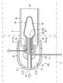
도2는 도1에 적용되는 본 발명의 제1 실시예에 따른 플라즈마 버너의 분해 사시도이고, 도3은 도2의 Ⅲ-Ⅲ 선을 따라 자른 단면도이다.FIG. 2 is an exploded perspective view of a plasma burner according to a first embodiment of the present invention applied to FIG. 1, and FIG. 3 is a cross-sectional view taken along line III-III of FIG.
도2 및 도3을 참조하면, 플라즈마 버너(100)는 베이스(40), 전극(50) 및 반응로(60)를 포함한다.2 and 3, the
베이스(40)는 연료 유입구(22), 적어도 하나의 배기가스 유입구(114)를 형성하며, 내부에 형성되는 혼합챔버(42)를 포함한다. 플라즈마 버너(100)는 배기관(4) 내에 설치되므로 배기가스의 흐름 방해를 최소화 하기 위하여, 배기가스 흐름에 대한 저항을 최소화하는 구조로 형성된다.The base 40 forms a
예를 들면, 베이스(40)는 엔진(2) 측(전극의 반대 측)을 향하여 볼록한 곡면 형상을 가진다. 엔진(2) 측에서 필터(8) 측으로 유동되는 배기가스는 베이스(40)의 볼록 곡면에 의하여 최소의 저항을 받으면서 필터(8) 측으로 안내될 수 있다.For example, the
전극(50)은 베이스(40)에 절연체(52)를 개재하여 장착되는 장착부(54)와, 장착부(54)에 연장되는 내부에 형성되는 흡열챔버(56)를 포함한다.The
베이스(40)의 연료 유입구(22)와 배기가스 유입구(114)로부터 각각 유입되는 연료 및 배기가스는 흡열챔버(56)로 유입되어 혼합기체 상태로 혼합되고 또한 가열된다. 절연체(52)는 전극(50)을 베이스(40) 또는 반응로(60)와 전기적으로 절연시킨다.Fuel and exhaust gas flowing from the
전극(50)은 장착부(54)의 베이스(40) 반대 측에서 확장되어 최대 확장부를 형성하고 이어서 점진적으로 좁아지는 형상을 가진다. 즉 흡열챔버(56)는 대략 원추 형상으로 이루어진다.The
장착부(54)는 2중 관에 의한 2중 통로를 형성하며, 내측에 형성되는 제1 통로(154)와, 제1 통로(154)의 외측에 형성되는 제2 통로(254)를 포함한다. 제1 통로(154)에는 배기가스 유입구(114)가 연결된다. 제2 통로(254)에는 흡열챔버(56)와 혼합챔버(42)가 연결된다.The mounting
배기가스 유입구(114)는 제1 통로(154)를 통하여 전극(50)의 중심에 형성되는 흡열챔버(56)에 연결된다. 연료 유입관로(12)는 배기가스 유입구(114) 내부를 통하여 흡열챔버(56)에 연결된다.The
연료 유입관로(12)로 공급되는 연료는 흡열챔버(56)의 일측까지 공급되고, 연료 유입관로(12) 끝에서는 배기가스 유입구(114)로 공급되는 배기가스에 의하여 흡열챔버(56) 내에 혼합기체 상태로 분사된다.Fuel supplied to the
흡열챔버(56)에서 가열된 혼합기체는 제2 통로(254)를 통하여 베이스(40)에 형성된 혼합챔버(42)로 공급된다.The mixed gas heated in the
혼합챔버(42)에는 배기가스 유입구(114)가 연결된다. 배기가스 유입구(114)로 공급되는 배기가스는 혼합챔버(42) 내의 혼합기체를 혼합기 분사구(66)를 통하 여 반응로(60) 내부로 분사한다.An
반응로(60)는 전극(50)을 내장하여 베이스(40)에 연결되며, 베이스(40)의 반대 측에 화염분출구(28)를 형성한다. 반응로(60)의 내벽은 전극(50)과 이격 상태를 유지한다.The
반응로(60)가 원통 형상이고, 전극(50)이 점진적으로 좁아지는 형상에 의하여, 반응로(60)의 내벽과 전극(50) 사이의 거리는 점진적으로 멀어진다. 즉 흡열챔버(56) 측에서 전극(50)의 외면과 반응로(60)의 내벽 사이의 거리는 최대 확장부에서 최단거리를 형성하고 전극(50)이 좁아짐에 따라 점진적으로 장거리를 형성한다.The distance between the inner wall of the
예를 들면, 반응로(60)와 베이스(40)는 배기관(4)의 길이 방향을 따라 일직선 상태로 배치되고, 서로 마주하는 외측을 용접이나 볼팅(bolting) 방법으로써 전극(50)을 내장한 상태로 연결된다.For example, the
반응로(60)는 측방에 구비되는 혼합기 분사구(66)를 통하여, 베이스(40)에 형성된 혼합챔버(42)와 연결되어 혼합챔버(42)로부터 혼합기체를 공급받는다.The
전극(50)에는 기설정된 전압(V)이 인가되고, 반응로(60)는 접지되므로 이격된 전극(50)과 반응로(60)의 내벽 사이에서 플라즈마 방전이 일어난다. 즉 전극(50)의 외면과 반응로(60) 내벽 사이에 형성되는 거리의 점진적 변화에 따라, 양자 사이에서 발생되는 플라즈마 방전은 확장된 거리를 따라 확장된다.Since a predetermined voltage V is applied to the
전극(50)과 반응로(60) 사이의 플라즈마 방전은 전극(50)과 반응로(60) 사이의 거리가 좁은 부분에서 발생되어 거리가 넓은 부분으로 확산된 후 소멸하고, 다시 좁은 부분에서 발생되어 넓은 부분으로 확산된 후 소멸하는 과정을 반복한다.Plasma discharge between the
연료 및 배기가스의 혼합기체에서의 플라즈마 방전은 연소 또는 수소와 일산화탄소를 포함하는 선산화물질로 일부 개질하여, 산화촉매(6)에서 산화를 용이하게 한다.Plasma discharge in a mixture of fuel and exhaust gas is combusted or partially reformed into a pre-oxide containing hydrogen and carbon monoxide, to facilitate oxidation in the
도4는 도3의 Ⅳ-Ⅳ 선을 따라 자른 단면도이다.4 is a cross-sectional view taken along the line IV-IV of FIG. 3.
도4를 참조하면, 혼합기 분사구(66)는 복수로 형성되어 반응로(60)에서 원주방향을 따라 가며 등간격으로 배치되고, 원통의 중심 방향에 대하여 기설정된 각으로 경사지게 형성된다.Referring to FIG. 4, a plurality of mixer injection holes 66 are formed and disposed at equal intervals along the circumferential direction in the
혼합기 분사구(66)를 통하여 혼합챔버(42)에서 반응로(60)로 유입되는 혼합기체는 혼합기 분사구(66)의 안내에 따라 반응로(60) 내에서 회전류(swirl)를 형성한다.The mixed gas flowing into the
복수의 등간격으로 배치되는 혼합기 분사구(66)는 반응로(60) 내에서 원주 방향을 따라 균일한 회전류를 형성하여, 반응로(60) 내부 공간을 효율적으로 활용할 수 있게 한다.The mixer injection holes 66 arranged at a plurality of equal intervals form a uniform rotational flow along the circumferential direction in the
전극(50)과 반응로(60) 사이에서 발생되는 플라즈마 방전은 혼합기 분사구(66)를 통하여 안내되는 혼합기체의 회전류에 의하여 화염을 형성하고, 화염은 화염분출구(28)를 통하여 반응로(60)에서 배기관(4)으로 분출된다. 화염은 배기가스를 가열시켜 필터(8) 상에 포집된 입자상 물질의 산화에 유리한 조건을 형성한다.Plasma discharge generated between the
이하 도5 내지 도11에 예시된 제2 실시예 내지 제8 실시예는 제1 실시예의 구성에 부가적인 구성을 추가한 것으로서, 제1 실시예와 비교하여 서로 유사 내지 동일한 부분에 대한 설명을 생략하고 서로 다른 부분에 대하여 설명한다.Hereinafter, the second to eighth embodiments illustrated in FIGS. 5 to 11 add additional components to the first embodiment, and descriptions of similar or identical parts to each other are omitted in comparison with the first embodiment. And explain the different parts.
도5는 본 발명의 제2 실시예에 따른 플라즈마 버너의 단면도이다.5 is a cross-sectional view of the plasma burner according to the second embodiment of the present invention.
도5를 참조하면, 플라즈마 버너(100)는 카울(cowl)(71)을 더 포함한다. 카울(71)은 반응로(60)의 전방에 배치되어 화염분출구(28)에서 분출되는 화염의 분출을 안내하여, 분출되는 화염과 반응로(60) 외부의 배기가스와의 급작스런 혼합으로 인해 화염이 불안정해지는 것을 방지할 수 있다. 카울(71)은 연결부재(72)를 통하여 반응로(60)의 외벽에 설치될 수 있다.Referring to FIG. 5, the
도6은 본 발명의 제3 실시예에 따른 플라즈마 버너의 단면도이다.6 is a cross-sectional view of a plasma burner according to a third embodiment of the present invention.
도6을 참조하면, 플라즈마 버너(100)는 카울(71)의 전방에 연료분사노즐(73)을 더 포함한다. 연료분사노즐(73)은 연료탱크(30)에 연결되어 연료를 공급받고, 카울(71)의 전방에 배치되어 카울(71)을 통하여 안내되는 화염에 연료를 분사한다.Referring to FIG. 6, the
화염에 분사된 연료는 화염의 열로 인하여 증발되고 상당 부분 연소되면서 배기가스의 추가적인 가열을 가능하게 한다.Fuel injected into the flame evaporates due to the heat of the flame and burns to a large extent, allowing further heating of the exhaust gases.
도7 내지 도9는 본 발명의 제4 실시예 내지 제6 실시예에 따른 플라즈마 버너의 단면도이다.7 to 9 are cross-sectional views of the plasma burners according to the fourth to sixth embodiments of the present invention.
도7 내지 도9를 참조하면, 플라즈마 버너(100)는 반응로(60)의 화염분출구(28) 주위에 유동교란부재(174, 274, 374)를 더 포함한다. 유동교란부재(174, 274, 374)는 도7 내지 도9에서 각각 서로 다르게 형성될 수 있다.7 to 9, the
도7을 참조하면, 유동교란부재(174)는 화염분출구(28)에서 반응로(60)의 외주에 돌출 형성된다. 유동교란부재(174)는 반응로(60)의 외주면과 배기관(4) 사이 에 흐르는 배기가스에 유동을 발생시켜, 화염분출구(28)로 분출되는 화염을 모아 안정화시킨다.Referring to FIG. 7, the
도8을 참조하면, 유동교란부재(274)는 화염분출구(28)의 전방에 이격 배치된다. 유동교란부재(274)는 화염분출구(28)의 내경보다 큰 내경을 가지는 원형띠로 형성될 수 있다. 유동교란부재(274)는 연결부재(75)를 통하여 반응로(60)의 전방에 설치될 수 있다. 유동교란부재(274)는 화염분출구(28)에서 분출되어 일정거리만큼 진행되어 퍼지려는 화염을 다시 모아 안정화시키고, 배기가스 중의 산소를 이용하여 미연소 연료를 추가로 연소시킬 수 있게 한다.Referring to Figure 8, the
도9를 참조하면, 유동교란부재(374)는 화염분출구(28)의 전방에서 화염분출구(28)의 중심에 대응하여 배치된다. 유동교란부재(374)는 원판으로 형성되어 연결부재(76)를 통하여 반응로(60)의 전방에 설치될 수 있다.Referring to FIG. 9, the
도9의 유동교란부재(374)는 반응로에서 돌출되는 미연소 액적의 접촉면을 제공하여 액적을 증발, 연소시키며, 화염과 배기가스의 급격한 혼합으로 화염이 불안정해지는 것을 방지한다..The
도10은 본 발명의 제7 실시예에 따른 플라즈마 버너의 단면도이다.10 is a sectional view of a plasma burner according to a seventh embodiment of the present invention.
도10을 참조하면, 연료 유입관로(12)는 열교환기(32)를 포함한다.Referring to FIG. 10, the
예를 들면, 연료 유입관로(12)의 열교환기(32)는 코일 형상으로 형성되어 배기관(4) 내에서의 흡열 면적을 증대시켜 연료 유입관로(12)로 공급되는 연료를 가열시킨다.For example, the
또한, 제7 실시예는 제2 실시예에 열교환기들(32, 34, 36)을 설치한 것을 예 시하고 있으며, 제1 실시예 및 제3 실시예 내지 제6 실시예 및 제8 실시예에도 동일하게 적용될 수 있다.In addition, the seventh embodiment shows that the
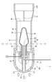
도11은 본 발명의 제8 실시예에 따른 플라즈마 버너의 단면도이다.11 is a sectional view of a plasma burner according to an eighth embodiment of the present invention.
도11을 참조하면, 전극(50)은 관통 형성되는 제3 통로(354)를 더 포함한다. 제3 통로(354)는 흡열챔버(56)를 반응로(60)의 내부에 직접 연결한다. 즉 제3 통로(354)는 대부분의 혼합기체가 제2 통로(254), 혼합챔버(42) 및 혼합기 분사구(66)를 경유할 때, 일부 혼합기체를 흡열챔버(56)에서 반응로(60)로 직접 분사되게 한다. 따라서 제3 통로(354)는 연료 공급관(12)을 통한 대량의 연료 공급을 가능하게 한다.Referring to FIG. 11, the
또한, 제8 실시예는 제1 실시예에 제3 통로(354)를 형성한 것을 예시하고 있으며, 제2 실시예 내지 제7 실시예에도 동일하게 적용될 수 있다.In addition, the eighth embodiment illustrates that the
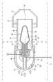
도12는 본 발명의 제9 실시예에 따른 플라즈마 버너의 단면도이다.12 is a sectional view of a plasma burner according to a ninth embodiment of the present invention.
도12를 참조하면, 배기가스 유입구들(114) 주위에는 배기가스 가이드(81)가 형성된다. 배기가스 가이드(81)는 베이스(40)에 분산 형성되어 있는 배기가스 유입구들(114)의 분포 면적보다 넓은 면적의 개구 및 개구로부터 점점 좁아지는 형상을 통하여, 배기가스를 배기가스 유입구(114)로 안내한다.Referring to FIG. 12, an
배기가스 가이드(81)는 대응하는 배기가스 유입구들(114)에 따라 제1 배기가스 가이드(181)와 제2 배기가스 가이드(281)를 포함한다. 제1 배기가스 가이드(181)는 혼합챔버(42)에 연결되는 배기가스 유입구(114) 쪽으로 배기가스를 유도하도록 배기가스 유입구(114) 주위에 형성된다.The
제2 배기가스 가이드(261)는 흡열챔버(56)에 연결되는 배기가스 유입구(114) 쪽으로 유도하도록 제1 배기가스 가이드(181) 내측에서 배기가스 유입구(114) 주위에 형성된다.The second exhaust gas guide 261 is formed around the
제1 배기가스 가이드(181)를 통하여 안내되는 배기가스는 배기가스 유입구(114)를 통하여 혼합챔버(42) 내부로 유입되면서 강한 흐름을 형성하여 혼합챔버(42) 및 혼합기 분사구(66)를 경유하는 혼합기의 흐름을 가속시킬 수 있다.The exhaust gas guided through the first
제2 배기가스 가이드(281)를 통하여 안내되는 배기가스는 배기가스 유입구(114)를 통하여 흡열챔버(56) 내부로 유입되면서 강한 흐름을 형성하여 연료 유입관로(12)로 공급되는 연료를 흡열챔버(56) 내에 분사시킨다.The exhaust gas guided through the second
또한, 제9 실시예는 제1 실시예에 배기가스 가이드(81) 및 제1, 제2 배기가스 가이드(81, 82)를 형성한 것을 예시하고 있으며, 제2 실시예 내지 제8 실시예에도 동일하게 적용될 수 있다.The ninth embodiment exemplifies that the
이상을 통해 본 발명의 바람직한 실시예에 대하여 설명하였지만, 본 발명은 이에 한정되는 것이 아니고 특허청구범위와 발명의 상세한 설명 및 첨부한 도면의 범위 안에서 여러 가지로 변형하여 실시하는 것이 가능하고 이 또한 본 발명의 범위에 속하는 것은 당연하다.Although the preferred embodiments of the present invention have been described above, the present invention is not limited thereto, and various modifications and changes can be made within the scope of the claims and the detailed description of the invention and the accompanying drawings. Naturally, it belongs to the scope of the invention.
도1은 본 발명의 일 실시예에 따른 매연여과장치의 블록도이다.1 is a block diagram of a soot filtration device according to an embodiment of the present invention.
도2는 도1에 적용되는 본 발명의 제1 실시예에 따른 플라즈마 버너의 분해 사시도이다.FIG. 2 is an exploded perspective view of a plasma burner according to a first embodiment of the present invention applied to FIG. 1.
도3은 도2의 Ⅲ-Ⅲ 선을 따라 자른 단면도이다.3 is a cross-sectional view taken along line III-III of FIG. 2.
도4는 도3의 Ⅳ-Ⅳ 선을 따라 자른 단면도이다.4 is a cross-sectional view taken along the line IV-IV of FIG. 3.
도5는 본 발명의 제2 실시예에 따른 플라즈마 버너의 단면도이다.5 is a cross-sectional view of the plasma burner according to the second embodiment of the present invention.
도6은 본 발명의 제3 실시예에 따른 플라즈마 버너의 단면도이다.6 is a cross-sectional view of a plasma burner according to a third embodiment of the present invention.
도7은 본 발명의 제4 실시예에 따른 플라즈마 버너의 단면도이다.7 is a sectional view of a plasma burner according to a fourth embodiment of the present invention.
도8은 본 발명의 제5 실시예에 따른 플라즈마 버너의 단면도이다.8 is a sectional view of a plasma burner according to a fifth embodiment of the present invention.
도9는 본 발명의 제6 실시예에 따른 플라즈마 버너의 단면도이다.9 is a sectional view of a plasma burner according to a sixth embodiment of the present invention.
도10은 본 발명의 제7 실시예에 따른 플라즈마 버너의 단면도이다.10 is a sectional view of a plasma burner according to a seventh embodiment of the present invention.
도11은 본 발명의 제8 실시예에 따른 플라즈마 버너의 단면도이다.11 is a sectional view of a plasma burner according to an eighth embodiment of the present invention.
도12는 본 발명의 제9 실시예에 따른 플라즈마 버너의 단면도이다.12 is a sectional view of a plasma burner according to a ninth embodiment of the present invention.
<도면의 주요부분에 대한 부호의 설명><Description of the symbols for the main parts of the drawings>
2 : 엔진4 : 배기관2: engine 4: exhaust pipe
6 : 산화촉매8 : 필터6: oxidation catalyst 8: filter
100 : 플라즈마 버너12 : 연료 유입관로100: plasma burner 12: fuel inlet pipe
22 : 연료 유입구114 : 배기가스 유입구22: fuel inlet 114: exhaust gas inlet
28 : 화염분출구28: flame outlet
30 : 연료탱크40 : 베이스30: fuel tank 40: base
50 : 전극60 : 반응로50
52 : 절연체54 : 장착부52: insulator 54: mounting portion
56 : 흡열챔버154, 254 : 제1, 제2 통로56:
42 : 혼합챔버354 : 제3 통로42: mixing chamber 354: third passage
66 : 혼합기 분사구71 : 카울(cowl)66: mixer nozzle 71: cowl (cowl)
72, 75, 76 : 연결부재73 : 연료분사노즐72, 75, 76: connecting member 73: fuel injection nozzle
174, 274, 374 : 유동교란부재32 : 열교환기174, 274, 374: flow disturbance member 32: heat exchanger
81 : 배기가스 가이드 181, 281 : 제1, 제2 배기가스 가이드81:
Claims (35)
Translated fromKoreanPriority Applications (7)
| Application Number | Priority Date | Filing Date | Title |
|---|---|---|---|
| KR1020070078579AKR100866328B1 (en) | 2007-08-06 | 2007-08-06 | Plasma Burner & Soot Filter |
| US12/134,557US8257455B2 (en) | 2007-07-30 | 2008-06-06 | Plasma burner and diesel particulate filter trap |
| EP08356112AEP2020487B1 (en) | 2007-07-30 | 2008-07-25 | Plasma burner and diesel particulate filter trap |
| EP11181993.4AEP2400123B1 (en) | 2007-07-30 | 2008-07-25 | Plasma burner and diesel particulate filter trap |
| JP2008194293AJP5086199B2 (en) | 2007-07-30 | 2008-07-29 | Plasma burner and smoke filter |
| CN2008101299994ACN101372910B (en) | 2007-07-30 | 2008-07-30 | Plasma burner and diesel particulate filter trap |
| JP2012032657AJP5473023B2 (en) | 2007-07-30 | 2012-02-17 | Plasma burner and smoke filter |
Applications Claiming Priority (1)
| Application Number | Priority Date | Filing Date | Title |
|---|---|---|---|
| KR1020070078579AKR100866328B1 (en) | 2007-08-06 | 2007-08-06 | Plasma Burner & Soot Filter |
Publications (1)
| Publication Number | Publication Date |
|---|---|
| KR100866328B1true KR100866328B1 (en) | 2008-10-31 |
Family
ID=40177901
Family Applications (1)
| Application Number | Title | Priority Date | Filing Date |
|---|---|---|---|
| KR1020070078579AExpired - Fee RelatedKR100866328B1 (en) | 2007-07-30 | 2007-08-06 | Plasma Burner & Soot Filter |
Country Status (1)
| Country | Link |
|---|---|
| KR (1) | KR100866328B1 (en) |
Cited By (2)
| Publication number | Priority date | Publication date | Assignee | Title |
|---|---|---|---|---|
| KR102425713B1 (en) | 2021-11-11 | 2022-07-27 | 강호림 | Device for plasma curtain appearance at atmospheric pressure using high voltage and magnetic force |
| WO2023085861A1 (en) | 2021-11-11 | 2023-05-19 | 강호림 | Plasma curtain generator in atmospheric pressure state using high voltage and magnetic force and low-vacuum incineration facility for low- and intermediate-level radioactive waste treatment using same |
Citations (3)
| Publication number | Priority date | Publication date | Assignee | Title |
|---|---|---|---|---|
| US5001899A (en) | 1987-06-24 | 1991-03-26 | Zeuna-Starker Gmbh & Co. Kg | Process and apparatus for the cleaning of a soot filter |
| KR19990027818A (en)* | 1997-09-30 | 1999-04-15 | 양재신 | Burner heated three-way catalytic inverter of gasoline engine |
| KR100622135B1 (en) | 2006-05-26 | 2006-09-11 | 한국기계연구원 | Diesel engine particulate filter Apparatus burner and diesel engine particulate filter comprising same |
- 2007
- 2007-08-06KRKR1020070078579Apatent/KR100866328B1/ennot_activeExpired - Fee Related
Patent Citations (3)
| Publication number | Priority date | Publication date | Assignee | Title |
|---|---|---|---|---|
| US5001899A (en) | 1987-06-24 | 1991-03-26 | Zeuna-Starker Gmbh & Co. Kg | Process and apparatus for the cleaning of a soot filter |
| KR19990027818A (en)* | 1997-09-30 | 1999-04-15 | 양재신 | Burner heated three-way catalytic inverter of gasoline engine |
| KR100622135B1 (en) | 2006-05-26 | 2006-09-11 | 한국기계연구원 | Diesel engine particulate filter Apparatus burner and diesel engine particulate filter comprising same |
Cited By (2)
| Publication number | Priority date | Publication date | Assignee | Title |
|---|---|---|---|---|
| KR102425713B1 (en) | 2021-11-11 | 2022-07-27 | 강호림 | Device for plasma curtain appearance at atmospheric pressure using high voltage and magnetic force |
| WO2023085861A1 (en) | 2021-11-11 | 2023-05-19 | 강호림 | Plasma curtain generator in atmospheric pressure state using high voltage and magnetic force and low-vacuum incineration facility for low- and intermediate-level radioactive waste treatment using same |
Similar Documents
| Publication | Publication Date | Title |
|---|---|---|
| KR100866327B1 (en) | Plasma Burner & Soot Filter | |
| JP5086199B2 (en) | Plasma burner and smoke filter | |
| CN105026712B (en) | Burner with air-assisted fuel nozzle and vaporization ignition system | |
| JP5555382B2 (en) | Exhaust purification device burner | |
| JP4794595B2 (en) | Diesel engine exhaust system | |
| US8959902B2 (en) | Exhaust treatment burner and mixer system | |
| KR100679869B1 (en) | Plasma reactor for DSP system and device for reducing particulate matter | |
| US9027331B2 (en) | Exhaust aftertreatment burner with preheated combustion air | |
| US20100319330A1 (en) | Burner for diesel particulate filter regeneration | |
| KR20090017476A (en) | Hot Gas Manufacturing Equipment and Methods, Diesel Particulate Filter Systems, Electronics and Computer Program Products | |
| WO2013161898A1 (en) | Exhaust purification device burner | |
| JP2005180371A (en) | Auxiliary device for exhaust gas after-treatment device | |
| KR100913606B1 (en) | Plasma Burner & Soot Filter | |
| KR101582625B1 (en) | CONCURRENTLY DECREASING SYSTEM FOR NOx AND PM OF DIESEL ENGINE USING PLASMA | |
| KR100866328B1 (en) | Plasma Burner & Soot Filter | |
| KR100866331B1 (en) | Plasma Burner & Soot Filter | |
| KR100699495B1 (en) | Plasma reactor for DSP system and reduction device of particulate matter using same | |
| KR100866330B1 (en) | Plasma Burner & Soot Filter | |
| KR100899223B1 (en) | Burner for DVD playback and the DSP system using the same | |
| KR100866329B1 (en) | Plasma Burner & Soot Filter | |
| CN116291810A (en) | Hot patching device and tail gas aftertreatment ware | |
| JP4794594B2 (en) | Diesel engine exhaust system | |
| CN209818143U (en) | Combustor for DPF regeneration | |
| CN114810290A (en) | Heating device for an exhaust system of an internal combustion engine | |
| WO2006099069A1 (en) | Plasma fuel reformer |
Legal Events
| Date | Code | Title | Description |
|---|---|---|---|
| A201 | Request for examination | ||
| PA0109 | Patent application | St.27 status event code:A-0-1-A10-A12-nap-PA0109 | |
| PA0201 | Request for examination | St.27 status event code:A-1-2-D10-D11-exm-PA0201 | |
| E902 | Notification of reason for refusal | ||
| PE0902 | Notice of grounds for rejection | St.27 status event code:A-1-2-D10-D21-exm-PE0902 | |
| P11-X000 | Amendment of application requested | St.27 status event code:A-2-2-P10-P11-nap-X000 | |
| P13-X000 | Application amended | St.27 status event code:A-2-2-P10-P13-nap-X000 | |
| E701 | Decision to grant or registration of patent right | ||
| PE0701 | Decision of registration | St.27 status event code:A-1-2-D10-D22-exm-PE0701 | |
| GRNT | Written decision to grant | ||
| PR0701 | Registration of establishment | St.27 status event code:A-2-4-F10-F11-exm-PR0701 | |
| PR1002 | Payment of registration fee | St.27 status event code:A-2-2-U10-U11-oth-PR1002 Fee payment year number:1 | |
| PG1601 | Publication of registration | St.27 status event code:A-4-4-Q10-Q13-nap-PG1601 | |
| PN2301 | Change of applicant | St.27 status event code:A-5-5-R10-R13-asn-PN2301 St.27 status event code:A-5-5-R10-R11-asn-PN2301 | |
| PR1001 | Payment of annual fee | St.27 status event code:A-4-4-U10-U11-oth-PR1001 Fee payment year number:4 | |
| FPAY | Annual fee payment | Payment date:20121002 Year of fee payment:5 | |
| PR1001 | Payment of annual fee | St.27 status event code:A-4-4-U10-U11-oth-PR1001 Fee payment year number:5 | |
| FPAY | Annual fee payment | Payment date:20130904 Year of fee payment:6 | |
| PR1001 | Payment of annual fee | St.27 status event code:A-4-4-U10-U11-oth-PR1001 Fee payment year number:6 | |
| FPAY | Annual fee payment | Payment date:20140917 Year of fee payment:7 | |
| PR1001 | Payment of annual fee | St.27 status event code:A-4-4-U10-U11-oth-PR1001 Fee payment year number:7 | |
| FPAY | Annual fee payment | Payment date:20150909 Year of fee payment:8 | |
| PR1001 | Payment of annual fee | St.27 status event code:A-4-4-U10-U11-oth-PR1001 Fee payment year number:8 | |
| P22-X000 | Classification modified | St.27 status event code:A-4-4-P10-P22-nap-X000 | |
| FPAY | Annual fee payment | Payment date:20160907 Year of fee payment:9 | |
| PR1001 | Payment of annual fee | St.27 status event code:A-4-4-U10-U11-oth-PR1001 Fee payment year number:9 | |
| FPAY | Annual fee payment | Payment date:20170907 Year of fee payment:10 | |
| PR1001 | Payment of annual fee | St.27 status event code:A-4-4-U10-U11-oth-PR1001 Fee payment year number:10 | |
| R18-X000 | Changes to party contact information recorded | St.27 status event code:A-5-5-R10-R18-oth-X000 | |
| PR1001 | Payment of annual fee | St.27 status event code:A-4-4-U10-U11-oth-PR1001 Fee payment year number:11 | |
| FPAY | Annual fee payment | Payment date:20190909 Year of fee payment:12 | |
| PR1001 | Payment of annual fee | St.27 status event code:A-4-4-U10-U11-oth-PR1001 Fee payment year number:12 | |
| PC1903 | Unpaid annual fee | St.27 status event code:A-4-4-U10-U13-oth-PC1903 Not in force date:20201028 Payment event data comment text:Termination Category : DEFAULT_OF_REGISTRATION_FEE | |
| PC1903 | Unpaid annual fee | St.27 status event code:N-4-6-H10-H13-oth-PC1903 Ip right cessation event data comment text:Termination Category : DEFAULT_OF_REGISTRATION_FEE Not in force date:20201028 | |
| R18-X000 | Changes to party contact information recorded | St.27 status event code:A-5-5-R10-R18-oth-X000 |