KR100860890B1 - Backlit transmissive display - Google Patents
Backlit transmissive displayDownload PDFInfo
- Publication number
- KR100860890B1 KR100860890B1KR1020047003476AKR20047003476AKR100860890B1KR 100860890 B1KR100860890 B1KR 100860890B1KR 1020047003476 AKR1020047003476 AKR 1020047003476AKR 20047003476 AKR20047003476 AKR 20047003476AKR 100860890 B1KR100860890 B1KR 100860890B1
- Authority
- KR
- South Korea
- Prior art keywords
- light
- delete delete
- conditioner
- transmissive display
- chamber
- Prior art date
- Legal status (The legal status is an assumption and is not a legal conclusion. Google has not performed a legal analysis and makes no representation as to the accuracy of the status listed.)
- Expired - Fee Related
Links
Images


Classifications
- G—PHYSICS
- G02—OPTICS
- G02F—OPTICAL DEVICES OR ARRANGEMENTS FOR THE CONTROL OF LIGHT BY MODIFICATION OF THE OPTICAL PROPERTIES OF THE MEDIA OF THE ELEMENTS INVOLVED THEREIN; NON-LINEAR OPTICS; FREQUENCY-CHANGING OF LIGHT; OPTICAL LOGIC ELEMENTS; OPTICAL ANALOGUE/DIGITAL CONVERTERS
- G02F1/00—Devices or arrangements for the control of the intensity, colour, phase, polarisation or direction of light arriving from an independent light source, e.g. switching, gating or modulating; Non-linear optics
- G02F1/01—Devices or arrangements for the control of the intensity, colour, phase, polarisation or direction of light arriving from an independent light source, e.g. switching, gating or modulating; Non-linear optics for the control of the intensity, phase, polarisation or colour
- G02F1/13—Devices or arrangements for the control of the intensity, colour, phase, polarisation or direction of light arriving from an independent light source, e.g. switching, gating or modulating; Non-linear optics for the control of the intensity, phase, polarisation or colour based on liquid crystals, e.g. single liquid crystal display cells
- G02F1/133—Constructional arrangements; Operation of liquid crystal cells; Circuit arrangements
- G02F1/1333—Constructional arrangements; Manufacturing methods
- G02F1/1335—Structural association of cells with optical devices, e.g. polarisers or reflectors
- G—PHYSICS
- G02—OPTICS
- G02B—OPTICAL ELEMENTS, SYSTEMS OR APPARATUS
- G02B6/00—Light guides; Structural details of arrangements comprising light guides and other optical elements, e.g. couplings
- G02B6/0001—Light guides; Structural details of arrangements comprising light guides and other optical elements, e.g. couplings specially adapted for lighting devices or systems
- G02B6/0011—Light guides; Structural details of arrangements comprising light guides and other optical elements, e.g. couplings specially adapted for lighting devices or systems the light guides being planar or of plate-like form
- G02B6/0013—Means for improving the coupling-in of light from the light source into the light guide
- G02B6/0023—Means for improving the coupling-in of light from the light source into the light guide provided by one optical element, or plurality thereof, placed between the light guide and the light source, or around the light source
- G02B6/0031—Reflecting element, sheet or layer
- G—PHYSICS
- G02—OPTICS
- G02F—OPTICAL DEVICES OR ARRANGEMENTS FOR THE CONTROL OF LIGHT BY MODIFICATION OF THE OPTICAL PROPERTIES OF THE MEDIA OF THE ELEMENTS INVOLVED THEREIN; NON-LINEAR OPTICS; FREQUENCY-CHANGING OF LIGHT; OPTICAL LOGIC ELEMENTS; OPTICAL ANALOGUE/DIGITAL CONVERTERS
- G02F1/00—Devices or arrangements for the control of the intensity, colour, phase, polarisation or direction of light arriving from an independent light source, e.g. switching, gating or modulating; Non-linear optics
- G02F1/01—Devices or arrangements for the control of the intensity, colour, phase, polarisation or direction of light arriving from an independent light source, e.g. switching, gating or modulating; Non-linear optics for the control of the intensity, phase, polarisation or colour
- G02F1/13—Devices or arrangements for the control of the intensity, colour, phase, polarisation or direction of light arriving from an independent light source, e.g. switching, gating or modulating; Non-linear optics for the control of the intensity, phase, polarisation or colour based on liquid crystals, e.g. single liquid crystal display cells
- G02F1/133—Constructional arrangements; Operation of liquid crystal cells; Circuit arrangements
- G02F1/1333—Constructional arrangements; Manufacturing methods
- G02F1/1335—Structural association of cells with optical devices, e.g. polarisers or reflectors
- G02F1/1336—Illuminating devices
- G02F1/133615—Edge-illuminating devices, i.e. illuminating from the side
Landscapes
- Physics & Mathematics (AREA)
- General Physics & Mathematics (AREA)
- Optics & Photonics (AREA)
- Nonlinear Science (AREA)
- Mathematical Physics (AREA)
- Chemical & Material Sciences (AREA)
- Crystallography & Structural Chemistry (AREA)
- Planar Illumination Modules (AREA)
- Liquid Crystal (AREA)
- Devices For Indicating Variable Information By Combining Individual Elements (AREA)
- Liquid Crystal Substances (AREA)
Abstract
Description
Translated fromKorean본 발명은 투과형 디스플레이, 보다 구체적으로는 투과형 디스플레이와 함께 사용하기 위한 백라이트 조립체에 관한 것이다.The present invention relates to a transmissive display, and more particularly to a backlight assembly for use with a transmissive display.
투과형 디스플레이 시스템은 일반적으로 영상을 가시적으로 제시하기 위해서 투과된 광의 특성을 변경시킴으로써 기능을 수행한다. 종래의 투과형 디스플레이 시스템은 일반적으로 투과형 디스플레이를 비추는 광원을 포함한다. 투과형 디스플레이는 예를 들어 비디오 보드 또는 디스플레이 드라이버로부터 입력 신호 (input signal)를 수용한다. 입력 신호는 디스플레이 시스템에 의해 디스플레이되어야 하는 이미지를 규정한다. 투과형 디스플레이는 광원으로부터의 빛이 투과형 디스플레이를 통해 통과할 때 상기 빛을 변경시켜 입력 신호에 의해 규정된 영상의 가시적 표시를 제공한다.Transmissive display systems generally perform a function by altering the properties of the transmitted light to visually present the image. Conventional transmissive display systems generally include a light source that illuminates the transmissive display. Transmissive displays, for example, receive input signals from video boards or display drivers. The input signal defines the image to be displayed by the display system. Transmissive displays alter the light as light from the light source passes through the transmissive display to provide a visual representation of the image defined by the input signal.
광원으로부터의 빛, 즉 백라이트는 대개 투과형 디스플레이의 조명 전에 컨디셔닝을 필요로 한다. 예를 들어 투과형 디스플레이는 빛이 휘도 및(또는) 색상에서 공간적으로 균일한 것을 필요로 할 수 있다. 또한, 일부 투과형 디스플레이는 빛이 편광되는 것을 필요로 한다. 다양한 종래의 백라이트 조립체 장치가 투과형 디스플레이에 적절한 조명을 제공하기 위하여 개발되었다. 백라이트 조립체를 개선시킴으로써, 투과형 디스플레이 시스템에 의해 생성된 가시적 표시의 외관이 또한 개선될 수 있다.Light from a light source, ie a backlight, usually requires conditioning before illumination of the transmissive display. For example, transmissive displays may require light to be spatially uniform in brightness and / or color. In addition, some transmissive displays require light to be polarized. Various conventional backlight assembly devices have been developed to provide adequate illumination for transmissive displays. By improving the backlight assembly, the appearance of the visible display produced by the transmissive display system can also be improved.
<발명의 개요><Overview of invention>
일반적으로, 본 발명은 투과형 디스플레이 시스템에서 사용하기 위한 백라이트 조립체에 관한 것이다. 투과형 디스플레이 시스템은 백라이트 조립체에 의해 비추어지는 투과형 디스플레이, 예를 들어 액정 디스플레이 ("LCD")를 포함한다. 백라이트 조립체는 광 챔버를 비추는 광원을 포함한다. 투과형 디스플레이는 광 챔버를 빠져나온 빛이 투과형 디스플레이를 비추도록 광 챔버에 인접하게 배치된다. 백라이트 조립체는 하나 이상의 반사기 및 광 챔버를 빠져나온 빛이 적절하게 컨디셔닝되고 강도가 충분히 균일하도록 보장하기 위해 하나 이상의 다른 광학 부재를 포함할 수 있다. 즉, 광학 부재는 빛을 컨디셔닝시켜 백라이트 조립체를 빠져나온 빛이 예를 들어 요구되는 공간적 균일성, 편광, 색상 및 각 분포를 포함한 요구되는 조명 특성을 갖도록 하기 위해 사용된다. 상기 방식에서, 백라이트 조립체는 투과형 디스플레이가 영상의 가시적 표시를 정확하게 표현할 수 있도록 투과형 디스플레이에 적절한 조명을 제공할 수 있다.In general, the present invention relates to a backlight assembly for use in a transmissive display system. Transmissive display systems include transmissive displays, such as liquid crystal displays ("LCDs"), illuminated by a backlight assembly. The backlight assembly includes a light source that illuminates the light chamber. The transmissive display is disposed adjacent the light chamber such that light exiting the light chamber illuminates the transmissive display. The backlight assembly may include one or more reflectors and one or more other optical members to ensure that light exiting the light chamber is properly conditioned and sufficiently uniform in intensity. That is, the optical member is used to condition the light so that the light exiting the backlight assembly has the required illumination characteristics including, for example, the required spatial uniformity, polarization, color, and angular distribution. In this manner, the backlight assembly can provide appropriate illumination to the transmissive display so that the transmissive display can accurately represent the visual display of the image.
다양한 실시태양에 대한 추가의 상세한 설명은 첨부하는 도면과 아래에서 설명하는 상세한 설명에 제시된다. 다른 특징, 목적 및 잇점은 상세한 설명 및 도면, 및 특허청구범위로부터 분명하게 알 수 있다.Further details of various embodiments are set forth in the accompanying drawings and the description below. Other features, objects, and advantages will be apparent from the description and drawings, and from the claims.
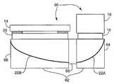
도 1은 본 발명에 따른 투과형 디스플레이 시스템의 측면 단면도이다.1 is a side cross-sectional view of a transmissive display system according to the present invention.
도 2 및 3은 본 발명에 따른 제1 컨디셔너의 예시적 실시태양의 측면 단면도이다.2 and 3 are side cross-sectional views of an exemplary embodiment of a first conditioner according to the present invention.
도 4는 본 발명에 따른 예시적 제2 컨디셔너의 측면 단면도이다.4 is a side cross-sectional view of an exemplary second conditioner in accordance with the present invention.
도 5 및 6은 본 발명에 따른 투과형 디스플레이 시스템의 추가의 실시태양의 측면 단면도이다.5 and 6 are side cross-sectional views of a further embodiment of a transmissive display system according to the present invention.
도 7은 투과형 디스플레이 시스템에 사용하기 위한 백라이트 조립체 (100)의 다른 실시태양의 투시도이다.7 is a perspective view of another embodiment of a
도 8 및 9는 하나 초과의 광 챔버를 이용하는 백라이트 조립체의 측면 단면도이다.8 and 9 are side cross-sectional views of a backlight assembly using more than one light chamber.
도 10은 본 발명에 따른 디스플레이를 비추는 방법의 일례를 보여주는 흐름도이다.10 is a flowchart showing an example of a method of illuminating a display according to the present invention.
도 11은 본 발명에 따른 다른 투과형 디스플레이 시스템의 측면 단면도이다.11 is a side cross-sectional view of another transmissive display system in accordance with the present invention.
도 1은 본 발명에 따른 투과형 디스플레이 시스템 (10)의 측면 단면도이다. 상기 시스템 (10)은 백라이트 조립체 (12) 및 투과형 디스플레이 (14)를 포함한다. 투과형 디스플레이 (14)는 예를 들어 디스플레이될 영상을 규정하는 입력 신호를 수용하기 위해 비디오 보드 (도시하지 않음)에 커플링된다. 백라이트 조립체 (12)는 투과형 디스플레이 (14)가 영상의 가시적 표시를 생산하기 위해 입력 신호에 따라 변경시키는 빛을 제공한다. 예를 들어 투과형 디스플레이 (14)는 액정 디스플레이 ("LCD")와 같은 광 밸브 또는 광원으로부터의 조명을 필요로 하는 임의의 다 른 투과형 디스플레이일 수 있다.1 is a side cross-sectional view of a
백라이트 조립체 (12)는 예를 들어 하나 이상의 점상(point-like) 광원, 예를 들어 발광 다이오드 ("LED")를 포함하는 광원 (16)을 포함한다. 별법으로, 광원 (16)은 형광 램프 등을 포함한 임의의 광 생산 장치를 포함할 수 있다. 그러나, 형광 램프는 비교적 부피가 크고, 전기적으로 소음이 있으며, 상당한 양의 에너지를 사용할 수 있다. 상기 이유로, LED와 같은 반도체 광원이 일반적으로 바람직하다. 비교하면, 반도체 광원은 비교적 소량의 에너지를 필요로 하며, 백라이트 조립체 (12)의 크기를 현저하기 감소시키기 위해 다른 광원 대신 사용될 수 있다. 예로서, 광원 (16)은 3색상 LED, 예를 들어 모델 NSCM310 (일본 소재의 니치아 코포레이션 (Nichia Corporation)으로부터 입수가능함) 또는 백색 LED, 예를 들어 모델 NSCW100 (또한 니치아 코포레이션으로부터 입수가능함)을 포함할 수 있다. 일부 실시태양에서, 광원 (16)은 집합적으로 목적하는 빛을 생산하는 다수의 LED를 나타낸다.The
백라이트 조립체 (12)는 또한 제1 컨디셔너 (18), 즉 프리 컨디셔너 (pre-conditioner)를 포함할 수 있다. 예를 들어 제1 컨디셔너 (18)은 광원 (16)으로부터 방출되는 빛의 편광, 공간적 균일성, 각 분포 및(또는) 색상을 변경시킬 수 있다. 상기 방식에서, 광원 (16)으로부터 방출된 빛은 투과형 디스플레이 (14)의 조명에 사용하기 위해 변용될 수 있다. 제1 컨디셔너 (18)의 특히 효과적인 몇가지 실시태양을 아래에서 보다 상세히 기술한다.The
제1 컨디셔너 (18)을 통해 통과하는 빛은 광 챔버 (20)에 들어간다. 반사기 (22)는 제1 컨디셔너 (18)에 의해 컨디셔닝된 빛을 반사시키기 위해 광 챔버 (20) 내에 존재한다. 광 챔버 (20)은 비어있을 수 있거나 (반사기 (22)를 제외하고) 또는 충전제 물질, 예를 들어 고체 유리 또는 플라스틱으로 충전될 수 있다. 예를 들어 충전제 물질은 컨디셔너 (18) 대신 빛을 컨디셔닝하기 위해 사용될 수 있다. 광 챔버 (20)의 하나 이상의 벽이 반사성일 수 있다.Light passing through the
반사기 (22)에서 반사된 빛은 제2 컨디셔너 (26), 즉 포스트 컨디셔너 (post conditioner)를 향해 간다. 제2 컨디셔너 (26)의 구체적인 실시태양은 아래에 보다 상세히 개관한다. 간단히, 제2 컨디셔너 (26)은 투과형 디스플레이 (14)를 비추기 위해 사용되기 직전에 빛을 추가로 컨디셔닝한다. 제2 컨디셔너는 또한 바람직하지 않은 빛을 여과하거나 반사시킬 수 있다. 제2 컨디셔너 (26)의 외부면 주위에 구멍 (28)이 형성될 수 있다. 이어서, 제2 컨디셔너 (26)에 의해 컨디셔닝된 빛은 투과형 디스플레이 (14)를 비추기 위해 구멍 (28)을 통해 통과할 수 있다.The light reflected at the
반사기 (22)는 광 챔버 (20)를 내부 부분 (24)와 외부 부분 (25)으로 나누는 것으로 보일 수 있다. 내부 및 외부 부분 (24 및 25)는 비어있을 수 있거나, 또는 내부 및 외부 부분 (24 및 25) 중 하나 또는 둘 모두가 충전제 물질을 포함할 수 있다. 예를 들어 하나의 실시태양에서, 반사기 (22)는 단지 부분적으로 반사성이다. 이 경우, 반사기 (22)를 통해 통과하는 빛은 반사기 (22)를 통해 내부 부분 (24)에 다시 들어가기 전에 외부 부분 (25)의 벽 또는 외부 부분 (25) 내의 확산성 충전제 물질에서 반사될 수 있다. 상기 방식에서, 빛은 투과형 디스플레이 (14)의 효과적인 조명원으로서 사용하기 위해 컨디셔닝될 때까지 광 챔버 (20) 내에서 확 산되고 재순환될 수 있다.The
반사기 (22)는 광 챔버 (20)의 내부 또는 외부 부분 (24, 25)를 한정하는 성형 표면 상에 침적된 고도 또는 부분 반사 코팅을 포함할 수 있다. 별법으로, 반사기 (22)는 적합한 필름 기판을 코팅함으로써 제조된 반사성 필름을 포함할 수 있다. 반사기 (22)는 또한 목적하는 스펙트럼 범위에서 높은 반사도 또는 부분적 반사도를 갖는 중합체 다층 광학 필름 ("MOF")을 포함할 수 있다. 예를 들어 반사기 (22)는 적외광을 투과시키면서 400 nm 내지 700 nm의 전체 가시 파장 범위에 걸쳐 반사시키는 반사성 MOF 또는 원하는 만큼 보다 좁은 스펙트럼 범위를 반사시키는 착색-거울 (colored-mirror) MOF일 수 있다. 두 경우 모두에서, 반사성 MOF는 바람직한 파장을 갖는 빛만을 투과형 디스플레이 (14)를 향해 반사시킴으로써 투과형 디스플레이 시스템 (10)에 잇점을 제공할 수 있다.The
반사기 (22)는 또한 실질적으로 한가지 유형의 편광을 갖는 빛을 반사시키는 중합체 MOF 반사형 편광기일 수 있다. 예를 들어, 반사기는 제1 선형 편광을 갖는 빛을 반사시키고 직교하는 선형 편광을 갖는 빛을 통과시킬 수 있거나, 또는 제1 원형 편광을 갖는 빛을 반사시키고 반대의 원형 편광을 갖는 빛을 투과시킬 수 있다. 선형 반사기 편광기의 한 예는 미국 미네소타주 세인트폴 소재의 미네소타 마이닝 앤드 매뉴팩쳐링 컴퍼니 (Minnesota Mining and Manufacturing Company)로부터 입수가능한 이중 휘도 향상 필름 (Dual Brightness Enhancing Film, "DBEF")이다. 반사성 원형 편광기의 한 예는 콜레스테릭 (cholesteric) 필름, 예를 들어 일본 소재의 닛도-덴코 (Nitto-Denko)로부터 입수가능한 Nipocs (등록상표) 필름이 다. 예를 들어 광 챔버 (20)에 들어가는 빛을 편광시키기 위해 또는 백라이트 조립체 (12)에서 사용된 다른 편광기를 증대시키기 위해 편광된 반사성 필름이 사용될 수 있다. 이는 투과형 디스플레이 (14)가 편광된 빛을 필요로하는 디스플레이인 경우 디스플레이 시스템 (10)의 유효성을 향상시킬 수 있다.
반사기 (22)는 평탄한 정반사성 필름과 같은 정반사기일 수 있다. 정반사성 필름은 반사시 빛의 원형 편광을 역전시키는 역할을 할 수 있거나, 반사기 (22)는 선형 편광을 회전시키는 역할을 하는 4분할파 (quarter-wave) 거울일 수 있다. 반사시 상기 편광 역전은 하기하는 몇몇 실시태양에서와 같이 반사성 편광기를 이용하는 편광 재순환 방식에서 유용할 수 있다. 정반사성 필름은 종래의 백라이트 조립체에서 종종 사용된 패턴형성된 반사성 표면 또는 성형 플라스틱 챔버에 비해 개선된 빛 제어를 제공한다. 추가로, 정반사성 필름은 일반적으로 패턴형성된 반사성 표면 또는 성형 플라스틱 챔버보다 빛을 보내는데 있어서 보다 효율적이다.The
반사기 (22)의 표면 조직은 투과형 디스플레이 (14)의 조명의 공간 균일도를 개선시키기 위해 일반적으로 평탄하다. 반사기 (22)의 형상은 최종 백라이트 출력의 휘도를 최대화시키기 위해 사용될 수 있다. 예를 들어 반사기 (22)는 제1 컨디셔너 (12)로부터 제2 컨디셔너 (26)으로 빛을 집중시키기 위한 방식으로 만곡될 수 있다. 별법으로 또는 부가적으로, 반사기 (22)는 최종 백라이트 출력의 균일도를 개선시킬 수 있다. 만곡은 포물선 또는 돔 형상을 만들 수 있다. 예를 들어 정반사성 필름은 내부 또는 외부 부분들 중 하나 또는 둘 모두가 충전제 물질로 충전되는 경우 내부 부분 (24) 또는 외부 부분 (25)의 표면을 따라 포물선 모양으로 만곡 될 수 있다.The surface texture of the
반사기 (22)는 또한 예를 들어 광 챔버 (20)에 삽입시키기 전에 사전형성될 수 있다. 사출 성형 공정, 캐스트 및 경화 공정 또는 사출 성형 공정과 캐스트 및 경화 공정의 조합이 반사기 (22)를 형성하기 위해 이용될 수 있다. 두 경우 모두에, 반사기 (22)는 적절하게 성형된 플라스틱 표면 상에 반사성 코팅을 포함할 수 있거나 또는 열형성된 거울 필름을 포함할 수 있다. 반사기 (22)가 패턴형성된 표면을 필요로 하지 않으면 반사기 (22)의 생성은 단순화될 수 있다.The
투과형 디스플레이 시스템 (10)은 종래의 장치에 비해 몇가지 잇점을 제공한다. 특히, 광 챔버 디자인은 백라이트 조립체 (12)가 비교적 콤팩트한 크기를 가질 수 있도록 한다. 원하는 경우, 광 가이드 및(또는) 부피가 큰 형광 램프의 사용을 피할 수 있다. 더욱이, 반사기 (22)는 종래의 패턴형성된 반사기 또는 비정반사성 성형된 플라스틱 챔버에 비해 효율 및 제어의 잇점을 제공하도록 경면 반사기일 수 있다. 또한, 제1 컨디셔너 (18) 및 제2 컨디셔너 (26)은 제조 비용을 더욱 경감시키기 위해 백라이트 조립체 (12)의 조립 이전에 제작될 수 있다. 중요하게는, 백라이트 조립체 (12)는 투과형 디스플레이 (14)의 조명에 사용하기 위해 빛을 효과적으로 컨디셔닝할 수 있다. 적절하게 컨디셔닝되지 않은 빛은 광원 (16)을 보다 효율적으로 이용하기 위해 광 챔버 (20) 내에서 여과되거나 가능하게는 재순환될 수 있다.The
도 2 및 3은 제1 컨디셔너 (18)의 예시적 실시태양의 측면 단면도이다. 도 2에 도시한 바와 같이, 제1 컨디셔너 (18A)의 하우징 (32)는 캐비티 (34)를 형성한 다. 캐비티 (34)는 뿔모양 구성을 가질 수 있으며, 여기서 캐비티 (34)의 단면 직경은 빛이 진행하는 방향으로 보다 커진다. 캐비티 (34)는 광원 (화살표로 나타낸 바와 같이)으로부터 빛이 그를 통해 들어갈 수 있는 홀 (hole)과 함께 형성된다. 캐비티 (34)의 내부 측벽은 반사성일 수 있어서, 큰 각으로 캐비티에 들어오는 빛은 제1 컨디셔너 (18A)를 통해 진행하도록 내부 측벽에서 반사되거나 산란될 수 있다. 확산기 (diffuser) 필름 (36)이 캐비티 (34)의 보다 큰 측면에 존재할 수 있다. 확산기 필름 (36)은 제1 컨디셔너 (18A)를 빠져나오는 빛의 강도가 공간적으로 보다 균일하도록 들어오는 빛을 확산시킨다. 즉, 캐비티 (34)에 들어가는 빛은 하나 이상의 점 광원으로부터 올 수 있으며, 따라서 확산기 필름 (36)을 향해 보내진 빛은 확산기 필름 (36)의 입구면 상의 특정 위치에서 훨씬 더 강할 수 있다. 그러나, 확산기 필름 (36)을 빠져나오는 빛의 강도는 확산기 필름 (36)의 출구면에 비해 공간적으로 보다 더 균일할 수 있다. 이는 다시 궁극적으로 투과형 디스플레이 (14)를 비추는 빛의 공간 균일도를 개선시킬 수 있다 (도 1).2 and 3 are side cross-sectional views of an exemplary embodiment of the
확산기 필름 (36)은 캐리어 필름 상에 표면 확산기 또는 확산성 코팅을 포함할 수 있다. 별법으로, 기판이 없는 벌크 확산기가 확산기 필름 (36)을 구현시키기 위해 사용될 수 있다. 다른 예에서, 백색 성형된 플라스틱의 얇은 섹션이 사용될 수 있다. 캐비티 (24)와 확산기 필름 (36)의 조합은 빛이 확산기 필름 (36)의 표면적에 걸쳐 실질적으로 균일한 강도가 되도록 빛을 제1 컨디셔너 (18A)로부터 보내는 역할을 할 수 있다. 예로서, 적합한 확산기 필름은 다른 투명 필름의 표면을 거칠게함으로써 생성될 수 있다. 별법으로, 수지 및 산란 입자를 포함하는 코 팅이 투명 필름에 도포된 다음 경화되어 적합한 확산기 필름을 구현시킬 수 있다.
일부 실시태양에서, 프레넬 (Fresnel) 렌즈 (38)이 확산기 필름 (36)에 인접하게 배치될 수 있다. 프레넬 렌즈 (38)은 광 챔버 (20)에 들어오는 빛의 각 분포를 감소시키기 위한 비교적 조밀한 경로를 제공한다 (도 1). 프레넬 렌즈 (38)은 성형된 플라스틱의 별개의 조각을 포함할 수 있거나, 또는 광 챔버 (20)의 가장자리의 성형 부분을 형성할 수 있다. 별법으로, 프레넬 렌즈 (38)은 제1 컨디셔너 (18A)의 가장자리의 성형된 부분을 형성할 수 있다. 프레넬 렌즈 (38)은 선형, 원형 또는 타원형 홈 구조를 가질 수 있다. 어떠한 경우든, 프레넬 렌즈 (38)의 존재는 궁극적으로 투과형 디스플레이 (14)에 대한 조명 효과를 개선시킬 수 있다. 프레넬 렌즈 (38)의 대체품으로서, 홀로그래픽 (holographic) 광학 부재 ("HOE")가 사용될 수 있다.In some embodiments, a
도 3은 제1 컨디셔너 (18)의 또다른 실시태양을 도시한다. 도 3에서, 제1 컨디셔너 (18B)는 확산기 물질 (42)로 충전된 캐비티를 포함한다. 확산기 물질은 들어오는 빛을 확산시켜, 제1 컨디셔너 (18B)를 빠져나오는 빛의 강도가 보다 균일하도록 만든다. 적합한 확산기 물질은 예를 들어 수지를 산란 입자와 합하고 혼합물을 제1 컨디셔너 (18B)의 캐비티 내로 주입함으로써 형성될 수 있다. 이어서, 상기 혼합물을 경화시킬 수 있다. 산란 입자의 예는 이산화티탄 또는 경화된 수지의 굴절률과 상이한 굴절률을 갖는 투명 물질을 포함한다.3 shows another embodiment of the
캐비티를 확산기 물질로 충전하는 것은 도 2의 실시태양에 비해 빛의 확산을 개선시킬 수 있다. 그러나, 캐비티를 확산기 물질로 충전하는 것은 확산기 필름을 사용하는 것보다 더 어렵고 비용이 많이 들 수 있다. 몇몇 실시태양에서, 캐비티가 확산기 물질로 충전될 수 있고 확산기 필름이 또한 사용될 수 있다. 다시, 프레넬 렌즈 (38)이 광 챔버 (20)에 들어오는 빛의 각 분포를 감소시키기 위해 또한 사용될 수 있다 (도 1). 편광기 필름 (도시하지 않음)이 광 챔버 (20)에 들어오는 빛을 적절하게 편광시키기 위해 또한 사용될 수 있다. 적합한 편광기 필름의 예는 일본 소재의 산리쯔 (Sanritz)로부터 입수가능한 HLC25618S 필름이다.Filling the cavity with diffuser material may improve light diffusion over the embodiment of FIG. 2. However, filling the cavity with diffuser material can be more difficult and expensive than using a diffuser film. In some embodiments, the cavity may be filled with a diffuser material and a diffuser film may also be used. Again,
또 다른 실시태양에서, 제1 컨디셔너 (18)은 제1 파장을 갖는 빛을 제2 파장을 갖는 빛으로 전환시키는 필름 또는 코팅을 포함한다. 예를 들어 광원 (16)은 자외선 ("UV") 광을 방출할 수 있다. 이 경우, 제1 컨디셔너 (18)은 UV광을 가시 스펙트럼 내의 빛으로 전환시키는 형광 물질을 포함하는 필름, 코팅 또는 충전제 물질을 포함할 수 있다.In another embodiment, the
도 4는 제2 컨디셔너 (26)의 하나의 특정 실시태양의 측면 단면도이다. 제2 컨디셔너 (26)은 제2 컨디셔너 (26)으로부터 나오는 광이 요구되는 스펙트럼 함량, 적합한 광 분포 및 요구되는 편광 상태를 갖도록 하기 위해 다양한 필름 또는 성형 광학 성분을 포함할 수 있다. 예를 들어, 제2 컨디셔너 (26)은 입사광 (화살표로 나타낸)을 시준하기 위해서 프레넬 렌즈 (46)을 포함할 수 있다.4 is a side cross-sectional view of one particular embodiment of a
제2 컨디셔너 (26)은 또한 반사형 편광기 (48)을 포함할 수 있다. 반사형 편광기 (48)은 목적하지 않는 편광의 빛을 재순환을 위해 다시 광 챔버내로 반사시킴으로써 휘도 향상 성분으로서 기능할 수 있다. 즉, 반사형 편광기 (48)은 적절하게 편광된 빛만이 통과하도록 허용할 수 있다. 목적하지 않는 편광을 갖는 빛은 반사된다. 반사형 편광기 (48)로부터 반사된 빛은 광 챔버로 다시 들어가고, 가능하게는 정확하게 편광된 다음 이후 반사형 편광기 (48)을 통해 통과할 수 있다. 상기 방식에서, 광원 (16)으로부터의 빛은 보다 효율적으로 사용될 수 있다. 적합한 반사형 편광기의 예는 미네소타 마이닝 앤드 매뉴팩쳐링 컴퍼니로부터 입수가능한 DBEF이다.The
제2 컨디셔너 (26)은 또한 광 챔버 (20)을 빠져나가는 빛의 각 분포를 감소시키는 역할을 하는 하나 이상의 프리즘 (prismatic) 필름 (52)를 포함할 수 있다. 예를 들어 프리즘 필름 (52)는 광 챔버 (20)을 빠져나가는 빛을 프리즘 필름 (52)에 대해 특정한 각으로 재배향시킬 수 있다. 프리즘 필름 (52)에 의해 재배향된 빛은 또한 재순환되어, 궁극적으로 프리즘 필름 (52)를 통해 통과할 각으로 광 챔버 (20)를 빠져나올 수 있다. 예를 들어, 미네소타 마이닝 앤드 매뉴팩쳐링 컴퍼니로부터 입수가능한 휘도 향상 필름 (Brightness Enhancing Film, "BEF")이 프리즘 필름 (52)를 구현시키기 위해 사용될 수 있다. 별법으로, 프리즘 필름 (52)는 미네소타 마이닝 앤드 매뉴팩쳐링 컴퍼니로부터 입수가능한 TRAF를 포함할 수 있다. TRAF는 큰 각으로 들어오는 빛을 상이한 각으로 빠져나가도록 재배향시킨다.The
일부 실시태양에서, 하나 초과의 프리즘 필름 (52)가 서로 인접하지만 서로에 대해 90도 회전되어 배치될 수 있다. 이 경우, 2개의 프리즘 필름은 "교차 (crossed) 프리즘 필름"으로서 칭해지는 것을 총체적으로 포함할 수 있다.In some embodiments, more than one
제2 컨디셔너 (26)은 또한 확산기 필름 (50)과 편광기 필름 (54)를 포함할 수 있다. 확산기 필름 (50)은 빛의 공간 균일도를 개선시킬 수 있다. 또한, 확산 기 필름은 목적하지 않는 파장의 빛을 여과시키도록 착색될 수 있다. 별법으로, 별개의 색상 필터 (도시하지 않음)가 원하는 스펙트럼 출력을 보장하기 위해 사용될 수 있다. 편광기 필름 (54)는 목적하지 않는 편광을 갖는 빛을 흡수하거나 반사시키고 목적하는 편광의 빛을 투과시킨다. 구멍 (56)이 제2 컨디셔너 (26)을 빠져나가는 빛의 광학 품질을 저하시킬 수 있는 미광 (stray light)을 차단하기 위해 또한 추가될 수 있다. 적합한 확산기 필름과 적합한 편광기 필름의 예는 상기 언급하였다.The
제2 컨디셔너 (26)의 부품들은 다양한 순서로 배열될 수 있다. 그러나, 제2 컨디셔너 (26)은 부품들이 도 4에 예시된 바와 같이 배열될 때 가장 효과적으로 작동할 수 있다. 예를 들어, 빛은 프레넬 렌즈 (46), 이어서 확산기 필름 (50), 이어서 프리즘 필름 (52), 이어서 반사형 편광기 (48), 이어서 편광기 (54)를 통해 통과한 후 최종적으로 구멍 (56)을 통해 통과할 수 있다.The parts of the
다시 도 1을 참조하면, 부품들간의 연결을 용이하게 하기 위해 하나 이상의 상이한 부품은 또한 부가적인 특징을 포함될 수 있다. 예를 들어 제2 컨디셔너 (26)은 투과형 디스플레이 (14)의 하우징과 연결시키기 위하여 테이퍼드 (tapered) 프레임 및 클립 등을 포함할 수 있다. 유사하게, 제1 컨디셔너 (18)은 광원 (16)과의 연결을 용이하게 하기 위한 특징을 포함할 수 있다. 예를 들어 기계적인 부재가 연결을 용이하게 할 수 있거나, 또는 별법으로, 접착제 또는 결합 물질이 사용될 수 있다.Referring again to FIG. 1, one or more different components may also include additional features to facilitate connection between the components. For example, the
도 5는 본 발명에 따른 투과형 디스플레이 시스템 (60)의 또다른 실시태양의 측면 단면도이다. 상기 실시태양에서, 광 챔버 (62)는 2개의 별도의 광 챔버 구역 (64 및 66)을 포함한다. 추가의 제3 컨디셔너 (68)은 2개의 광 챔버 구역 (64 및 66) 사이에 위치할 수 있다. 이러한 형태는 광원 (16)이 제2 컨디셔너 (26)과 동일한 광 챔버 (62)의 면에 위치하는 것을 가능하게 한다. 즉, 투과형 디스플레이 시스템 (60)에서, 광원 (16)은 투과형 디스플레이 (14)와 공통 측면을 따라 배치된다. 투과형 디스플레이 (14) 및 광원 (16)을 광 챔버 (62)의 공통 측면을 따라 배치함으로써, 투과형 디스플레이 (14) 및 광원 (16)은 종래의 투과형 디스플레이 시스템에서 종종 사용된 부가적인 가요성 (flex) 회로의 필요없이 주회로판에 직접 커플링될 수 있다. 즉, 광원 (16) 및 투과형 디스플레이 (14)는 주회로판에 직접 커플링될 수 있다. 그러나, 주회로판은 투과형 디스플레이 (16)의 시청을 위해 홀과 함께 형성될 필요가 있을 수 있다.5 is a side cross-sectional view of another embodiment of a
작동시, 광원 (16)으로부터의 빛은 제1 컨디셔너 (18)을 통해 통과할 때 컨디셔닝된다. 이어서, 빛은 빛을 제3 컨디셔너 (68)을 향해 반사시키는 형상을 갖는 반사기 (22A)로부터 반사된다. 빛은 제3 컨디셔너 (68)을 통해 통과하고, 빛을 제2 컨디셔너 (26)을 향해 반사시키는 형상을 갖는 반사기 (22B)로부터 반사된다. 이어서, 빛은 제2 컨디셔너 (26)을 통해 통과하여 투과형 디스플레이 (14)를 비춘다. 반사기 (22A 및 22B)는 상기한 반사기 (22) (도 1)와 유사할 수 있다. 유사하게, 제1 컨디셔너 (18)은 도 2 또는 3에 예시된 것과 유사할 수 있고, 제2 컨디셔너 (26)은 도 4에 예시된 것과 유사할 수 있다. 제3 컨디셔너 (68)은 요구되는 특성에 따라 빛을 추가로 컨디셔닝시키는 하나 이상의 광학 부재, 예를 들어 확산기 필름 또는 편광기 필름을 포함할 수 있다. 적합한 편광기 필름 및 적합한 확산기 필름은 상기 언급한 바 있다.In operation, light from
도 5에 관한 하나의 실시태양에서, 반사기 (22A) 및 반사기 (22B)는 단일 반사성 필름을 포함한다. 이 경우에, 반사성 필름은 반사기 (22A) 및 반사기 (22B) 모두를 규정하도록 형성된 반사성 편광기 또는 거울 필름일 수 있다.In one embodiment with respect to FIG. 5,
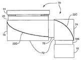
도 6은 본 발명에 따른 투과형 디스플레이 시스템 (70)의 또다른 실시태양의 단면 측면도이다. 이 실시태양에서, 광 챔버 (72)는 다시 2개의 별개의 광 챔버 구역 (74 및 76)을 포함하고, 추가의 제3 컨디셔너 (78)은 2개의 광 챔버 구역 (74)과 (76) 사이에 위치할 수 있다. 이 형태는 제2 컨디셔너 (26)에 대하여 광 챔버 (72)의 반대편 상에 광원 (16)이 위치하는 것을 허용하다. 즉, 투과형 디스플레이 시스템 (70)에서, 광원 (16)은 투과형 디스플레이 (14)에 대하여 광 챔버 (72)의 반대편에 위치한다. 광 챔버 (62)의 반대편을 따라 투과형 디스플레이 (14) 및 광원 (16)을 위치시키면 잇점을 얻을 수 있다. 예를 들어, 주회로판에 광원 (16)을 커플링시키기 위해 종래의 투과형 디스플레이 시스템에서 종종 사용된 부가적인 가요성 회로를 사용할 필요성을 제거할 수 있다. 종래의 장치와는 달리, 도 6의 실시태양은 광원 (16)이 주회로판에 직접 커플링될 수 있도록 한다. 투과형 디스플레이 (14)만이 가요성 회로를 필요로 할 것이다. 도 5의 실시태양보다 우수한 잇점으로서, 투과형 디스플레이 (14)는 회로판 상에 임의의 부가적인 홀을 형성하지 않으면서 볼 수 있다.6 is a cross-sectional side view of another embodiment of a
작동시, 광원 (16)으로부터의 빛은 제1 컨디셔너 (18)을 통하여 통과할 때 컨디셔닝된다. 이어서, 빛은 빛을 제3 컨디셔너 (78)을 향하여 반사시키는 형상을 갖는 반사기 (22C)에서 반사된다. 빛은 제3 컨디셔너 (78)을 통해 통과하고, 빛을 제2 컨디셔너 (26)을 향하여 반사시키는 형상을 갖는 반사기 (22D)에서 반사된다. 이어서, 빛은 제2 컨디셔너 (26)을 통해 통과하고, 투과형 디스플레이 (14)를 비춘다. 다시, 반사기 (22C 및 22D)는 상기 설명한 반사기 (22) (도 1)과 유사할 수 있다. 유사하게, 제1 컨디셔너 (18)은 도 2 또는 3에 도시한 것과 유사할 수 있고, 제2 컨디셔너 (26)은 도 4에 도시한 것과 유사할 수 있다. 제3 컨디셔너 (78)는 요구되는 특성에 따라 빛을 추가로 컨디셔닝시키는 하나 이상의 광학 성분, 예를 들어 확산기 필름 또는 편광기 필름을 포함할 수 있다.In operation, light from
도 6에 관한 하나의 실시태양에서, 반사기 (22C) 및 반사기 (22D)는 단일 반사성 필름을 포함한다. 이 경우, 반사성 필름은 반사형 편광기일 필요가 있다. 단일 반사성 필름은 또한 제3 컨디셔너 (78)의 부재를 포함할 것이다. 반사성 필름은 제3 컨디셔너 (78)을 통해 만곡하는 반사기 (22C) 및 반사기 (22D)를 모두 규정하도록 형성될 수 있다. 반사형 편광기의 투과축은 반사기 (22C)에서 반사된 빛이 제3 컨디셔너 (78)을 통해 통과하도록 보장하기 위해 챔버의 가장자리에 대해 45도인 것이 바람직하다.In one embodiment with respect to FIG. 6, reflector 22C and
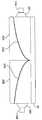
도 7은 투과형 디스플레이 시스템에 사용하기 위한 백라이트 조립체 (100)의 또다른 실시태양의 투시도이다. 도시한 바와 같이, 백라이트 조립체 (100)은 빛을 제1 컨디셔너 (18)을 통해 통과시키는 광원 (16)을 포함한다. 이어서, 빛은 빛을 제3 컨디셔너 (108)을 향하여 반사시키는 형상을 갖는 반사기 (22E)에서 반사된다. 빛은 제3 컨디셔너 (108)을 통해 통과하고, 빛을 제2 컨디셔너 (26)을 향하여 반사시키는 형상을 갖는 반사기 (22F)에서 반사된다. 이어서, 빛은 제2 컨디셔너 (26)을 통해 통과한다. 투과형 디스플레이 (도시하지 않음)는 조명되는 제2 컨디셔너 (26)에 인접하여 위치할 수 있다. 도 7에 도시한 장치는 몇몇 콤팩트한 디스플레이 시스템에 대해 공간 잇점을 제공할 수 있다.7 is a perspective view of another embodiment of a
도 8 및 9는 하나 초과의 광 챔버를 이용하는 백라이트 조립체의 측면 단면도이다. 이들 실시태양은 투과형 디스플레이에 대해 증가된 조명 면적을 갖는 백라이팅 시스템을 구현하기 위해 상기 개시된 내용의 조합을 이용한다. 예를 들어, 도 8에 도시한 바와 같이, 광원 (14A 및 14B)는 각각 빛을 제1 컨디셔너 (18C 및 18D)을 통해 광 챔버 (20A 및 20B) 내로 통과시킬 수 있다. 이어서, 빛은 제2 컨디셔너 (26)의 조명 전에 반사기 (22G 및 22H)에서 반사될 수 있다. 투과형 디스플레이 (도시하지 않음)는 조명되는 제2 컨디셔너 (26)에 인접하여 위치할 수 있다. 제2 컨디셔너 (26)은 광 챔버 (20A 및 20B)의 연결 라인을 따라 균일한 조명을 달성하기 위해 상단 확산기 필름, 즉 제2 컨디셔너 (26)의 최외부층을 포함하는 추가의 확산기 필름을 추가로 포함할 수 있다.8 and 9 are side cross-sectional views of a backlight assembly using more than one light chamber. These embodiments utilize a combination of the above disclosed to implement a backlighting system with increased illumination area for transmissive displays. For example, as shown in FIG. 8,
도 9은 다른 실시예를 예시한 것이다. 도 9에서, 광원 (14C 및 14D)는 각각 빛을 제1 컨디셔너 (18E 및 18F)를 통해 광 챔버 (20C 및 20D) 내로 통과시킨다. 이어서, 빛은 제2 컨디셔너 (26)을 비추기 전에 반사기 (22G 및 22H)에서 반사된다. 다시, 투과형 디스플레이는 조명되는 제2 컨디셔너 (26)에 인접하여 위치할 수 있고, 제2 컨디셔너 (26)은 광 챔버 (14C 및 14D)의 연결 라인을 따라 균일한 조명을 달성하기 위해 상단 확산기 필름을 추가로 포함할 수 있다.9 illustrates another embodiment. In FIG. 9,
도 8 및 9의 실시태양은 투과형 디스플레이에 대한 조명 면적을 증가시키는 잇점을 제공할 수 있다. 그러나, 비교적 부피가 큰 부품의 사용을 계속 방지할 수 있기 때문에, 상기 시스템이 조명 면적의 크기에 대하여 비교적 콤팩트한 형태 팩터를 유지할 수 있다. 더욱 더 큰 조명 면적을 구현하기 위해 추가의 광원 및 광 챔버가 본 발명에 따라 조합될 수 있다.8 and 9 may provide the advantage of increasing the illumination area for transmissive displays. However, since the use of relatively bulky parts can be prevented, the system can maintain a relatively compact shape factor with respect to the size of the illumination area. Additional light sources and light chambers can be combined in accordance with the present invention to realize even larger illumination areas.
도 10은 본 발명에 따른 디스플레이를 비추는 방법의 일례를 보여주는 흐름도이다. 도시한 바와 같이, 광원은 제1 컨디셔너 (114)에 의해 컨디셔닝되는 광 (112)을 제공한다. 이어서, 제2 컨디셔너는 광을 반사하고(116), 컨디셔닝시킨다(118). 이어서, 디스플레이는 광 (120)으로 효과적으로 조명될 수 있다. 제1 및 제2 컨디셔너는 상기한 것에 실질적으로 대응할 수 있다. 마찬가지로, 반사기는 상기한 반사기 중의 하나에 실질적으로 대응할 수 있다. 예를 들어 반사기는 빛을 컨디셔닝시키기 위해 또한 사용될 수 있다. 부가적인 제3 컨디셔너 및 제2 반사기가 도 5 또는 도 6에 도시된 바와 같이 또한 사용될 수 있다.10 is a flowchart showing an example of a method of illuminating a display according to the present invention. As shown, the light source provides light 112 that is conditioned by the
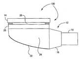
도 11은 본 발명의 또다른 실시태양에 따른 투과형 디스플레이 시스템 (130)의 측면 단면도이다. 특히, 투과형 디스플레이 시스템 (130)은 도 1에 예시된 시스템 (10)과 실질적으로 유사하다. 그러나, 투과형 디스플레이 시스템 (130)은 광 챔버의 외부 부분 (25) (도 1)을 제거한다. 대신, 내부 부분 (24)가 외부 부분없이 광 챔버를 구성한다.11 is a side cross-sectional view of a
본 발명은 몇가지 잇점을 제공할 수 있다. 예를 들어 본 발명은 백라이트 조립체의 크기를 감소시키기 위해 이용될 수 있다. 이는 미니어처 디스플레이, 즉 3 cm 미만의 대각선 크기를 갖는 것과 함께 사용하기에 특히 유리하다. 상기 디스플레이는 종종 디지탈 카메라 및 비디오 카메라의 뷰파인더에 또는 머리 장착형 비디오 디스플레이 등에 설치될 수 있다. 본 발명은 부피가 큰 종래의 부품을 사용하는 필요를 제거함으로써 비교적 콤팩트한 형태 팩터를 달성한다.The present invention can provide several advantages. For example, the present invention can be used to reduce the size of a backlight assembly. This is particularly advantageous for use with miniature displays, ie those having a diagonal size of less than 3 cm. The display can often be installed in the viewfinder of digital cameras and video cameras or in head mounted video displays or the like. The present invention achieves a relatively compact form factor by eliminating the need to use bulky conventional components.
예를 들어, 본 발명에 따라 구성된 광 챔버는 형광 램프에 의해 조명되는 평평한 광 가이드를 사용할 필요성을 제거한다. 형광 램프는 일반적으로 전기적 소음을 야기할 수 있는 다량의 전력 및 특수 고전압 드라이버를 필요로 한다. 그러나, 본 발명은 상기 고가의 부피가 큰 부품을 필요로 하지 않는다. 대신, 능률적인 "점상" 광원, 예를 들어 발광 다이오드가 광 가이드 및 형광 램프 대신 사용될 수 있다. 따라서, 형광 드라이버 회로에 대한 필요가 또한 제거된다.For example, a light chamber constructed in accordance with the present invention obviates the need to use a flat light guide illuminated by a fluorescent lamp. Fluorescent lamps generally require large amounts of power and special high voltage drivers that can cause electrical noise. However, the present invention does not require such expensive bulky parts. Instead, an efficient "pointing" light source, such as a light emitting diode, can be used in place of the light guide and the fluorescent lamp. Thus, the need for a fluorescent driver circuit is also eliminated.
본 발명은 광을 반사시키기 위해 광 챔버 내의 평탄한 정반사기를 이용할 수 있다. 평탄한 정반사기는 패턴형성된 반사기 또는 비정반사성 성형 플라스틱 챔버에 비해 백라이팅 시스템의 효율을 개선시킬 수 있다. 더욱이, 평탄한 정반사기는 패턴형성된 반사기 또는 비정반사성 성형 플라스틱 챔버에 비해 보다 우수한 광 조절성을 제공할 수 있다.The present invention can utilize a flat specular reflector in a light chamber to reflect light. Flat specular reflectors can improve the efficiency of the backlighting system compared to patterned reflectors or non-reflective molded plastic chambers. Moreover, flat specular reflectors can provide better light control compared to patterned reflectors or non-reflective molded plastic chambers.
본 발명은 요구되는 휘도 및 색상의 공간 균일도를 갖는 투과형 디스플레이를 비추기 위해 별개의 점상 광원으로부터 광을 분배시키기 위한 효율적이고 효과적인 조립체를 제공한다. 더욱이, 일부 실시태양에서, 본 발명은 디스플레이를 주회로판에 연결시키는 고가의 연결기, 예를 들어 가요성 회로에 대한 필요성을 제거 할 수 있다. 디스플레이와 광원을 광 챔버의 공통면 또는 광 챔버의 반대면을 따라 위치시킴으로써 디스플레이는 추가의 가요성 회로에 대한 필요성없이 주회로판에 직접 커플링될 수 있다. 또다른 잇점은 제조 및 조립 비용에 관한 것이며, 이는 본 발명의 다양한 측면에 의해 현저하게 감소될 수 있다.The present invention provides an efficient and effective assembly for distributing light from separate point light sources to illuminate transmissive displays having the desired luminance and color spatial uniformity. Moreover, in some embodiments, the present invention may obviate the need for expensive connectors, such as flexible circuits, that connect the display to the main circuit board. By positioning the display and the light source along the common surface of the light chamber or opposite the light chamber, the display can be coupled directly to the main circuit board without the need for additional flexible circuitry. Another advantage relates to manufacturing and assembly costs, which can be significantly reduced by various aspects of the present invention.
본 발명의 상이한 실시태양을 설명하였다. 예를 들어, 백라이트 조립체는 투과형 디스플레이 시스템에서 사용하기 위한 것으로 설명하였다. 그러나, 본 발명의 범위를 벗어나지 않는 다양한 변형이 가능하다. 따라서, 다른 실시태양도 하기 특허청구범위에 포함된다.Different embodiments of the invention have been described. For example, the backlight assembly has been described for use in a transmissive display system. However, various modifications are possible without departing from the scope of the present invention. Accordingly, other embodiments are also included in the following claims.
Claims (41)
Translated fromKoreanApplications Claiming Priority (3)
| Application Number | Priority Date | Filing Date | Title |
|---|---|---|---|
| US09/949,948 | 2001-09-10 | ||
| US09/949,948US6663262B2 (en) | 2001-09-10 | 2001-09-10 | Backlighting transmissive displays |
| PCT/US2002/024510WO2003023277A1 (en) | 2001-09-10 | 2002-07-31 | Backlighting transmissive displays |
Publications (2)
| Publication Number | Publication Date |
|---|---|
| KR20040031068A KR20040031068A (en) | 2004-04-09 |
| KR100860890B1true KR100860890B1 (en) | 2008-09-29 |
Family
ID=25489722
Family Applications (1)
| Application Number | Title | Priority Date | Filing Date |
|---|---|---|---|
| KR1020047003476AExpired - Fee RelatedKR100860890B1 (en) | 2001-09-10 | 2002-07-31 | Backlit transmissive display |
Country Status (9)
| Country | Link |
|---|---|
| US (2) | US6663262B2 (en) |
| EP (1) | EP1425538B1 (en) |
| JP (1) | JP4331602B2 (en) |
| KR (1) | KR100860890B1 (en) |
| CN (1) | CN100422820C (en) |
| AT (1) | ATE381723T1 (en) |
| DE (1) | DE60224206T2 (en) |
| TW (1) | TWI274205B (en) |
| WO (1) | WO2003023277A1 (en) |
Cited By (1)
| Publication number | Priority date | Publication date | Assignee | Title |
|---|---|---|---|---|
| KR20110014046A (en)* | 2009-08-04 | 2011-02-10 | 엘지디스플레이 주식회사 | LCD and its design method |
Families Citing this family (97)
| Publication number | Priority date | Publication date | Assignee | Title |
|---|---|---|---|---|
| US5910854A (en) | 1993-02-26 | 1999-06-08 | Donnelly Corporation | Electrochromic polymeric solid films, manufacturing electrochromic devices using such solid films, and processes for making such solid films and devices |
| US5668663A (en)* | 1994-05-05 | 1997-09-16 | Donnelly Corporation | Electrochromic mirrors and devices |
| US6891563B2 (en) | 1996-05-22 | 2005-05-10 | Donnelly Corporation | Vehicular vision system |
| US6326613B1 (en) | 1998-01-07 | 2001-12-04 | Donnelly Corporation | Vehicle interior mirror assembly adapted for containing a rain sensor |
| US6124886A (en) | 1997-08-25 | 2000-09-26 | Donnelly Corporation | Modular rearview mirror assembly |
| US8294975B2 (en) | 1997-08-25 | 2012-10-23 | Donnelly Corporation | Automotive rearview mirror assembly |
| US6172613B1 (en) | 1998-02-18 | 2001-01-09 | Donnelly Corporation | Rearview mirror assembly incorporating vehicle information display |
| US8288711B2 (en) | 1998-01-07 | 2012-10-16 | Donnelly Corporation | Interior rearview mirror system with forwardly-viewing camera and a control |
| US6445287B1 (en) | 2000-02-28 | 2002-09-03 | Donnelly Corporation | Tire inflation assistance monitoring system |
| US6329925B1 (en) | 1999-11-24 | 2001-12-11 | Donnelly Corporation | Rearview mirror assembly with added feature modular display |
| US6693517B2 (en) | 2000-04-21 | 2004-02-17 | Donnelly Corporation | Vehicle mirror assembly communicating wirelessly with vehicle accessories and occupants |
| US6477464B2 (en) | 2000-03-09 | 2002-11-05 | Donnelly Corporation | Complete mirror-based global-positioning system (GPS) navigation solution |
| US7167796B2 (en) | 2000-03-09 | 2007-01-23 | Donnelly Corporation | Vehicle navigation system for use with a telematics system |
| US7370983B2 (en) | 2000-03-02 | 2008-05-13 | Donnelly Corporation | Interior mirror assembly with display |
| AU2001243285A1 (en) | 2000-03-02 | 2001-09-12 | Donnelly Corporation | Video mirror systems incorporating an accessory module |
| US7255451B2 (en) | 2002-09-20 | 2007-08-14 | Donnelly Corporation | Electro-optic mirror cell |
| AU2002251807A1 (en) | 2001-01-23 | 2002-08-19 | Donnelly Corporation | Improved vehicular lighting system for a mirror assembly |
| US7581859B2 (en) | 2005-09-14 | 2009-09-01 | Donnelly Corp. | Display device for exterior rearview mirror |
| US6948840B2 (en)* | 2001-11-16 | 2005-09-27 | Everbrite, Llc | Light emitting diode light bar |
| US6918674B2 (en) | 2002-05-03 | 2005-07-19 | Donnelly Corporation | Vehicle rearview mirror system |
| US7329013B2 (en) | 2002-06-06 | 2008-02-12 | Donnelly Corporation | Interior rearview mirror system with compass |
| AU2003237424A1 (en) | 2002-06-06 | 2003-12-22 | Donnelly Corporation | Interior rearview mirror system with compass |
| WO2004026633A2 (en) | 2002-09-20 | 2004-04-01 | Donnelly Corporation | Mirror reflective element assembly |
| US7310177B2 (en) | 2002-09-20 | 2007-12-18 | Donnelly Corporation | Electro-optic reflective element assembly |
| WO2004103772A2 (en) | 2003-05-19 | 2004-12-02 | Donnelly Corporation | Mirror assembly for vehicle |
| US6886954B2 (en)* | 2002-12-23 | 2005-05-03 | Intel Corporation | System and method for processing light in an electronic display system |
| US20040207774A1 (en)* | 2003-04-17 | 2004-10-21 | Gothard David L. | Illumination apparatus for LCD/organic displays |
| US7557876B2 (en) | 2003-07-25 | 2009-07-07 | Nitto Denko Corporation | Anisotropic fluorescent thin crystal film and backlight system and liquid crystal display incorporating the same |
| US7446924B2 (en) | 2003-10-02 | 2008-11-04 | Donnelly Corporation | Mirror reflective element assembly including electronic component |
| US7308341B2 (en) | 2003-10-14 | 2007-12-11 | Donnelly Corporation | Vehicle communication system |
| US7223005B2 (en)* | 2003-12-23 | 2007-05-29 | Lamb David J | Hybrid lightguide backlight |
| US7303322B2 (en)* | 2003-12-23 | 2007-12-04 | 3M Innovative Properties Company | Multiple lightguide backlight |
| US7213939B2 (en) | 2004-03-02 | 2007-05-08 | Hewlett-Packard Development Company, L.P. | Hue adjusting lighting system |
| US7450194B2 (en) | 2004-03-04 | 2008-11-11 | Nitto Denko Corporation | Polarized interference recycling backlight module and liquid crystal display incorporating the same |
| US7733443B2 (en) | 2004-03-09 | 2010-06-08 | Nitto Denko Corporation | LCD comprising backlight and reflective polarizer on front panel |
| US7456915B2 (en) | 2004-03-26 | 2008-11-25 | Nitto Denko Corporation | Liquid crystal display panel with broadband interference polarizers |
| TWI293707B (en)* | 2004-06-08 | 2008-02-21 | Prodisc Technology Inc | Liquid crystal display and backlight module |
| TWI293135B (en)* | 2004-06-08 | 2008-02-01 | Prodisc Technology Inc | Liquid crystal display and backlight module |
| JP4746301B2 (en)* | 2004-10-01 | 2011-08-10 | ライツ・アドバンスト・テクノロジー株式会社 | Backlight unit |
| DE202005016373U1 (en)* | 2004-11-09 | 2005-12-29 | Element Displays Dr. Wiemer Gmbh | Liquid crystal display device, has liquid crystal layer, polarization filter and dispersion layer or retro reflection layer that are arranged under intermediate joint of layers, and housing translucently designed in rear side of device |
| CN100395616C (en)* | 2004-12-11 | 2008-06-18 | 鸿富锦精密工业(深圳)有限公司 | Concentrating sheet and backlight module using the same |
| GB0427607D0 (en)* | 2004-12-16 | 2005-01-19 | Microsharp Corp Ltd | Structured optical film |
| US7559664B1 (en) | 2004-12-27 | 2009-07-14 | John V. Walleman | Low profile backlighting using LEDs |
| CN100406993C (en)* | 2005-02-01 | 2008-07-30 | 精碟科技股份有限公司 | Liquid crystal display device and backlight module thereof |
| EP1883855B1 (en) | 2005-05-16 | 2011-07-20 | Donnelly Corporation | Vehicle mirror assembly with indicia at reflective element |
| KR20060120373A (en)* | 2005-05-19 | 2006-11-27 | 삼성전자주식회사 | Backlight unit and LCD using the same |
| US20070081361A1 (en)* | 2005-10-12 | 2007-04-12 | Donald Clary | Light emitting diode backlight for liquid crystal displays |
| KR100699487B1 (en)* | 2005-10-18 | 2007-03-26 | 엘지전자 주식회사 | Light providing unit and backlight unit including the same |
| TWI331694B (en)* | 2005-10-20 | 2010-10-11 | Ind Tech Res Inst | Back-lighted structure |
| EP1949666B1 (en) | 2005-11-01 | 2013-07-17 | Magna Mirrors of America, Inc. | Interior rearview mirror with display |
| DE102005057166A1 (en)* | 2005-11-30 | 2007-05-31 | BSH Bosch und Siemens Hausgeräte GmbH | Display element for electrical appliance has light emitting diodes, beam path of light in display element that passes at least two light-scattering elements |
| EP2049365B1 (en)* | 2006-08-01 | 2017-12-13 | 3M Innovative Properties Company | Illumination device |
| KR100829015B1 (en)* | 2006-08-22 | 2008-05-14 | 엘지전자 주식회사 | Surface light source device, backlight unit and liquid crystal display device having same |
| WO2008035256A2 (en)* | 2006-09-19 | 2008-03-27 | Koninklijke Philips Electronics N.V. | Illumination system, luminaire and display device |
| US7548677B2 (en)* | 2006-10-12 | 2009-06-16 | Microsoft Corporation | Interactive display using planar radiation guide |
| CN101529156B (en)* | 2006-10-16 | 2012-03-21 | 皇家飞利浦电子股份有限公司 | Lighting device |
| US9028108B2 (en) | 2007-05-20 | 2015-05-12 | 3M Innovative Properties Company | Collimating light injectors for edge-lit backlights |
| WO2008144644A2 (en) | 2007-05-20 | 2008-11-27 | 3M Innovative Properties Company | Semi-specular components in hollow cavity light recycling backlights |
| CN101681056B (en) | 2007-05-20 | 2013-03-27 | 3M创新有限公司 | Backlight and display system using same |
| EP2487535A1 (en) | 2007-05-20 | 2012-08-15 | 3M Innovative Properties Company | Design parameters for backlights, which have a thin hollow cavity and recycle the light |
| JP5580193B2 (en)* | 2007-06-14 | 2014-08-27 | コーニンクレッカ フィリップス エヌ ヴェ | LED-based lighting fixture with adjustable beam shape |
| TWM327550U (en)* | 2007-09-13 | 2008-02-21 | Kun Dian Photoelectric Entpr Co | LED lamp structure with light-guiding plate |
| JP2009099271A (en)* | 2007-10-12 | 2009-05-07 | Harison Toshiba Lighting Corp | Hollow surface lighting device |
| JP5702151B2 (en) | 2008-02-07 | 2015-04-15 | スリーエム イノベイティブ プロパティズ カンパニー | Hollow backlight with structured film |
| JP5792464B2 (en) | 2008-02-22 | 2015-10-14 | スリーエム イノベイティブ プロパティズ カンパニー | BACKLIGHT HAVING SELECTIVE OUTPUT LIGHT DISTRIBUTION, DISPLAY SYSTEM USING SAME, AND METHOD FOR FORMING BACKLIGHT |
| US8177382B2 (en)* | 2008-03-11 | 2012-05-15 | Cree, Inc. | Apparatus and methods for multiplanar optical diffusers and display panels for using the same |
| US8154418B2 (en) | 2008-03-31 | 2012-04-10 | Magna Mirrors Of America, Inc. | Interior rearview mirror system |
| FR2931748B1 (en)* | 2008-05-29 | 2010-12-10 | Faurecia Interieur Ind | INTERIOR LIGHTING ELEMENT, DOOR AND MOTOR VEHICLE CORRESPONDING. |
| EP2297607B1 (en) | 2008-06-04 | 2014-04-23 | 3M Innovative Properties Company | Hollow backlight with tilted light source |
| US8206012B2 (en) | 2008-06-30 | 2012-06-26 | Production Resource Group, Llc | Layered dimmer system |
| WO2010037915A1 (en)* | 2008-10-02 | 2010-04-08 | Faurecia Interieur Industrie | Interior trim assembly for a motor vehicle and motor vehicle |
| US9487144B2 (en) | 2008-10-16 | 2016-11-08 | Magna Mirrors Of America, Inc. | Interior mirror assembly with display |
| KR101040769B1 (en)* | 2008-10-23 | 2011-06-10 | 김중철 | Pedestrian crossing |
| WO2010049759A1 (en)* | 2008-10-30 | 2010-05-06 | Faurecia Interieur Industrie | Process for manufacturing an automobile interior trim part with an airbag cover, and to the associated machine |
| KR101383930B1 (en)* | 2008-12-24 | 2014-04-10 | 엘지디스플레이 주식회사 | Light irradiation apparatus |
| JP5261245B2 (en)* | 2009-03-26 | 2013-08-14 | 株式会社ジャパンディスプレイウェスト | Backlight and display imaging device |
| BRPI1012268A2 (en)* | 2009-06-30 | 2016-04-05 | Sharp Kk | lighting device, display device and television receiver. |
| US9341887B2 (en) | 2009-09-11 | 2016-05-17 | Dolby Laboratories Licensing Corporation | Displays with a backlight incorporating reflecting layer |
| US20110193872A1 (en)* | 2010-02-09 | 2011-08-11 | 3M Innovative Properties Company | Control system for hybrid daylight-coupled backlights for sunlight viewable displays |
| EP2738445B1 (en)* | 2010-11-08 | 2018-01-10 | LG Innotek Co., Ltd. | Lighting apparatus |
| JP5406225B2 (en) | 2010-12-06 | 2014-02-05 | エルジー イノテック カンパニー リミテッド | Backlight unit |
| CN102121643A (en)* | 2011-01-31 | 2011-07-13 | 马瑞利汽车电子(广州)有限公司 | Backlight module |
| CN103133941B (en)* | 2011-12-01 | 2016-05-18 | 扬升照明股份有限公司 | Backlight module |
| JP6066564B2 (en)* | 2012-01-30 | 2017-01-25 | スリーエム イノベイティブ プロパティズ カンパニー | Lighting device |
| KR20140088679A (en)* | 2013-01-03 | 2014-07-11 | 삼성디스플레이 주식회사 | Backlight assembly and display device using the same |
| US9958601B2 (en)* | 2013-09-19 | 2018-05-01 | University Of Utah Research Foundation | Display backlight |
| US9690041B2 (en)* | 2013-12-17 | 2017-06-27 | Seoul Semiconductor Co., Ltd. | Air cavity LED backlight unit |
| CN104763919B (en)* | 2014-01-08 | 2017-04-12 | 扬升照明股份有限公司 | Light source module |
| EP3264145A1 (en)* | 2014-03-18 | 2018-01-03 | 3M Innovative Properties Company | Combiner optic |
| DE202014104900U1 (en)* | 2014-10-15 | 2016-01-18 | Zumtobel Lighting Gmbh | Lamp for use as a wallwasher |
| WO2016064947A1 (en) | 2014-10-23 | 2016-04-28 | Corning Incorporated | A light diffusing component and a method of manufacturing a light diffusing component |
| CN104793398A (en)* | 2015-04-08 | 2015-07-22 | 康佳集团股份有限公司 | Backlight module and back projection type liquid crystal television |
| CN104793284A (en)* | 2015-04-30 | 2015-07-22 | 武汉华星光电技术有限公司 | Light guiding plate, backlight module and liquid crystal display |
| WO2017039725A1 (en) | 2015-09-05 | 2017-03-09 | Leia Inc. | Dual-direction collimator |
| KR102493918B1 (en)* | 2016-03-09 | 2023-02-01 | 삼성전자주식회사 | Display apparatus |
| US10705289B2 (en)* | 2018-06-14 | 2020-07-07 | Sharp Kabushiki Kaisha | Lighting device and display device |
| KR20240027708A (en)* | 2021-06-30 | 2024-03-04 | 가부시키가이샤 한도오따이 에네루기 켄큐쇼 | Electronics |
Citations (2)
| Publication number | Priority date | Publication date | Assignee | Title |
|---|---|---|---|---|
| KR20000023750A (en)* | 1996-07-12 | 2000-04-25 | 크리스 로저 에이취. | Illumination sources and systems |
| KR20000070114A (en)* | 1997-01-13 | 2000-11-25 | 스프레이그 로버트 월터 | Luminaire device |
Family Cites Families (27)
| Publication number | Priority date | Publication date | Assignee | Title |
|---|---|---|---|---|
| GB2198867A (en)* | 1986-12-17 | 1988-06-22 | Philips Electronic Associated | A liquid crystal display illumination system |
| US4874228A (en)* | 1987-03-24 | 1989-10-17 | Minnesota Mining And Manufacturing Company | Back-lit display |
| JPS6444336A (en)* | 1987-08-10 | 1989-02-16 | Nissan Motor | Vehicle display device |
| US5283563A (en)* | 1990-03-20 | 1994-02-01 | General Electric Company | Backlighting of nematic curvilinear aligned phase liquid crystal display panels |
| US5190370A (en) | 1991-08-21 | 1993-03-02 | Minnesota Mining And Manufacturing Company | High aspect ratio lighting element |
| JPH05249459A (en)* | 1992-03-06 | 1993-09-28 | Sharp Corp | Liquid crystal display |
| US5387921A (en)* | 1992-10-08 | 1995-02-07 | Panocorp Display Systems | Scanning back illuminating light source for liquid crystal and other displays |
| US5390276A (en)* | 1992-10-08 | 1995-02-14 | Briteview Technologies | Backlighting assembly utilizing microprisms and especially suitable for use with a liquid crystal display |
| JP3362900B2 (en)* | 1993-03-09 | 2003-01-07 | 富士通株式会社 | Surface emitting device |
| US5440197A (en)* | 1993-10-05 | 1995-08-08 | Tir Technologies, Inc. | Backlighting apparatus for uniformly illuminating a display panel |
| US6313892B2 (en) | 1993-10-05 | 2001-11-06 | Teledyne Lighting And Display Products, Inc. | Light source utilizing reflective cavity having sloped side surfaces |
| US5471348A (en) | 1994-05-13 | 1995-11-28 | Minnesota Mining And Manufacturing Company | Directed reflection optical device |
| AU4409496A (en) | 1994-11-29 | 1996-06-19 | Precision Lamp, Inc. | Edge light for panel display |
| JP3251452B2 (en) | 1995-01-31 | 2002-01-28 | シャープ株式会社 | Backlight device for liquid crystal display device |
| DE69632813T2 (en) | 1995-08-23 | 2005-06-30 | Koninklijke Philips Electronics N.V. | LIGHTING SYSTEM FOR A FLAT PANEL IMAGE DISPLAY DEVICE |
| WO1997014984A1 (en)* | 1995-10-18 | 1997-04-24 | Minnesota Mining And Manufacturing Company | Totally internally reflecting light conduit |
| DE19538893A1 (en) | 1995-10-19 | 1997-04-24 | Bosch Gmbh Robert | Lighting fixture with a diffuser |
| US5931576A (en)* | 1996-02-26 | 1999-08-03 | North American Lighting, Inc. | Optical coupler for distributive lighting system |
| US5825543A (en)* | 1996-02-29 | 1998-10-20 | Minnesota Mining And Manufacturing Company | Diffusely reflecting polarizing element including a first birefringent phase and a second phase |
| EP0879991A3 (en) | 1997-05-13 | 1999-04-21 | Matsushita Electric Industrial Co., Ltd. | Illuminating system |
| US5976686A (en)* | 1997-10-24 | 1999-11-02 | 3M Innovative Properties Company | Diffuse reflective articles |
| US6285426B1 (en)* | 1998-07-06 | 2001-09-04 | Motorola, Inc. | Ridged reflector having optically transmissive properties for an optical display device |
| US6005649A (en)* | 1998-07-22 | 1999-12-21 | Rainbow Displays, Inc. | Tiled, flat-panel microdisplay array having visually imperceptible seams |
| US20010036546A1 (en)* | 1999-08-03 | 2001-11-01 | Kaytor Scott R. | Dimensionally stabilized diffuse reflective articles |
| GB0006327D0 (en) | 2000-03-16 | 2000-05-03 | 3M Innovative Properties Co | Light guides suitable for illuminated displays |
| US6282029B1 (en) | 2000-05-02 | 2001-08-28 | Agilent Technologies, Inc. | Compact display system |
| US6592234B2 (en)* | 2001-04-06 | 2003-07-15 | 3M Innovative Properties Company | Frontlit display |
- 2001
- 2001-09-10USUS09/949,948patent/US6663262B2/ennot_activeExpired - Lifetime
- 2002
- 2002-07-31EPEP02750394Apatent/EP1425538B1/ennot_activeExpired - Lifetime
- 2002-07-31JPJP2003527312Apatent/JP4331602B2/ennot_activeExpired - Fee Related
- 2002-07-31CNCNB028222571Apatent/CN100422820C/ennot_activeExpired - Fee Related
- 2002-07-31KRKR1020047003476Apatent/KR100860890B1/ennot_activeExpired - Fee Related
- 2002-07-31WOPCT/US2002/024510patent/WO2003023277A1/enactiveIP Right Grant
- 2002-07-31ATAT02750394Tpatent/ATE381723T1/ennot_activeIP Right Cessation
- 2002-07-31DEDE60224206Tpatent/DE60224206T2/ennot_activeExpired - Lifetime
- 2002-08-15TWTW091118413Apatent/TWI274205B/ennot_activeIP Right Cessation
- 2003
- 2003-11-06USUS10/702,976patent/US7293899B2/ennot_activeExpired - Fee Related
Patent Citations (2)
| Publication number | Priority date | Publication date | Assignee | Title |
|---|---|---|---|---|
| KR20000023750A (en)* | 1996-07-12 | 2000-04-25 | 크리스 로저 에이취. | Illumination sources and systems |
| KR20000070114A (en)* | 1997-01-13 | 2000-11-25 | 스프레이그 로버트 월터 | Luminaire device |
Cited By (2)
| Publication number | Priority date | Publication date | Assignee | Title |
|---|---|---|---|---|
| KR20110014046A (en)* | 2009-08-04 | 2011-02-10 | 엘지디스플레이 주식회사 | LCD and its design method |
| KR101649695B1 (en)* | 2009-08-04 | 2016-08-22 | 엘지디스플레이 주식회사 | Liquid crystal device and method for designing liquid crystal display device |
Also Published As
| Publication number | Publication date |
|---|---|
| CN1585871A (en) | 2005-02-23 |
| CN100422820C (en) | 2008-10-01 |
| EP1425538B1 (en) | 2007-12-19 |
| DE60224206D1 (en) | 2008-01-31 |
| US20040136172A1 (en) | 2004-07-15 |
| JP2005502904A (en) | 2005-01-27 |
| US20030048639A1 (en) | 2003-03-13 |
| US6663262B2 (en) | 2003-12-16 |
| JP4331602B2 (en) | 2009-09-16 |
| DE60224206T2 (en) | 2008-12-04 |
| WO2003023277A1 (en) | 2003-03-20 |
| KR20040031068A (en) | 2004-04-09 |
| ATE381723T1 (en) | 2008-01-15 |
| US7293899B2 (en) | 2007-11-13 |
| EP1425538A1 (en) | 2004-06-09 |
| TWI274205B (en) | 2007-02-21 |
Similar Documents
| Publication | Publication Date | Title |
|---|---|---|
| KR100860890B1 (en) | Backlit transmissive display | |
| JP5792464B2 (en) | BACKLIGHT HAVING SELECTIVE OUTPUT LIGHT DISTRIBUTION, DISPLAY SYSTEM USING SAME, AND METHOD FOR FORMING BACKLIGHT | |
| KR101143774B1 (en) | Back-light device | |
| JP4838986B2 (en) | Luminance profile generator | |
| US5926601A (en) | Stacked backlighting system using microprisms | |
| JP5990226B2 (en) | Semi-specular hollow backlight with gradient extraction | |
| JP3801032B2 (en) | Light source and liquid crystal display device using the light source | |
| KR100939854B1 (en) | Light guide luminaires provide monochromatic glow | |
| JP4153776B2 (en) | Planar light source device and liquid crystal display device using the same | |
| JP2004157472A (en) | Light guides and lighting devices | |
| CN1017289B (en) | Back lighting device | |
| KR20100126288A (en) | Hollow backlight with structured film | |
| CN101363995A (en) | Backlight module unit | |
| US6449439B1 (en) | Unitary light diffusing cavity | |
| KR20040075725A (en) | Spread illuminating apparatus adapted to allow light to exit out from both surfaces of light conductive plate | |
| JP3366078B2 (en) | Lighting equipment | |
| JP3377937B2 (en) | Reflective liquid crystal display | |
| JP2000195319A (en) | Backlight device with microprisms | |
| JPH10268297A (en) | Liquid crystal display device | |
| JP2004134222A (en) | Light guide plate and lighting device |
Legal Events
| Date | Code | Title | Description |
|---|---|---|---|
| PA0105 | International application | St.27 status event code:A-0-1-A10-A15-nap-PA0105 | |
| PG1501 | Laying open of application | St.27 status event code:A-1-1-Q10-Q12-nap-PG1501 | |
| R18-X000 | Changes to party contact information recorded | St.27 status event code:A-3-3-R10-R18-oth-X000 | |
| A201 | Request for examination | ||
| E13-X000 | Pre-grant limitation requested | St.27 status event code:A-2-3-E10-E13-lim-X000 | |
| P11-X000 | Amendment of application requested | St.27 status event code:A-2-2-P10-P11-nap-X000 | |
| P13-X000 | Application amended | St.27 status event code:A-2-2-P10-P13-nap-X000 | |
| PA0201 | Request for examination | St.27 status event code:A-1-2-D10-D11-exm-PA0201 | |
| E902 | Notification of reason for refusal | ||
| PE0902 | Notice of grounds for rejection | St.27 status event code:A-1-2-D10-D21-exm-PE0902 | |
| E13-X000 | Pre-grant limitation requested | St.27 status event code:A-2-3-E10-E13-lim-X000 | |
| P11-X000 | Amendment of application requested | St.27 status event code:A-2-2-P10-P11-nap-X000 | |
| P13-X000 | Application amended | St.27 status event code:A-2-2-P10-P13-nap-X000 | |
| E701 | Decision to grant or registration of patent right | ||
| PE0701 | Decision of registration | St.27 status event code:A-1-2-D10-D22-exm-PE0701 | |
| GRNT | Written decision to grant | ||
| PR0701 | Registration of establishment | St.27 status event code:A-2-4-F10-F11-exm-PR0701 | |
| PR1002 | Payment of registration fee | St.27 status event code:A-2-2-U10-U12-oth-PR1002 Fee payment year number:1 | |
| PG1601 | Publication of registration | St.27 status event code:A-4-4-Q10-Q13-nap-PG1601 | |
| PR1001 | Payment of annual fee | St.27 status event code:A-4-4-U10-U11-oth-PR1001 Fee payment year number:4 | |
| FPAY | Annual fee payment | Payment date:20120907 Year of fee payment:5 | |
| PR1001 | Payment of annual fee | St.27 status event code:A-4-4-U10-U11-oth-PR1001 Fee payment year number:5 | |
| FPAY | Annual fee payment | Payment date:20130906 Year of fee payment:6 | |
| PR1001 | Payment of annual fee | St.27 status event code:A-4-4-U10-U11-oth-PR1001 Fee payment year number:6 | |
| PR1001 | Payment of annual fee | St.27 status event code:A-4-4-U10-U11-oth-PR1001 Fee payment year number:7 | |
| FPAY | Annual fee payment | Payment date:20150819 Year of fee payment:8 | |
| PR1001 | Payment of annual fee | St.27 status event code:A-4-4-U10-U11-oth-PR1001 Fee payment year number:8 | |
| FPAY | Annual fee payment | Payment date:20160818 Year of fee payment:9 | |
| PR1001 | Payment of annual fee | St.27 status event code:A-4-4-U10-U11-oth-PR1001 Fee payment year number:9 | |
| FPAY | Annual fee payment | Payment date:20170818 Year of fee payment:10 | |
| PR1001 | Payment of annual fee | St.27 status event code:A-4-4-U10-U11-oth-PR1001 Fee payment year number:10 | |
| FPAY | Annual fee payment | Payment date:20180903 Year of fee payment:11 | |
| PR1001 | Payment of annual fee | St.27 status event code:A-4-4-U10-U11-oth-PR1001 Fee payment year number:11 | |
| PC1903 | Unpaid annual fee | St.27 status event code:A-4-4-U10-U13-oth-PC1903 Not in force date:20190924 Payment event data comment text:Termination Category : DEFAULT_OF_REGISTRATION_FEE | |
| PC1903 | Unpaid annual fee | St.27 status event code:N-4-6-H10-H13-oth-PC1903 Ip right cessation event data comment text:Termination Category : DEFAULT_OF_REGISTRATION_FEE Not in force date:20190924 |