KR100860843B1 - Autonomous driving device and method, and autonomous vehicle using same - Google Patents
Autonomous driving device and method, and autonomous vehicle using sameDownload PDFInfo
- Publication number
- KR100860843B1 KR100860843B1KR1020070081602AKR20070081602AKR100860843B1KR 100860843 B1KR100860843 B1KR 100860843B1KR 1020070081602 AKR1020070081602 AKR 1020070081602AKR 20070081602 AKR20070081602 AKR 20070081602AKR 100860843 B1KR100860843 B1KR 100860843B1
- Authority
- KR
- South Korea
- Prior art keywords
- target
- distance
- calculated
- information
- driving
- Prior art date
- Legal status (The legal status is an assumption and is not a legal conclusion. Google has not performed a legal analysis and makes no representation as to the accuracy of the status listed.)
- Expired - Fee Related
Links
Images


Classifications
- G—PHYSICS
- G05—CONTROLLING; REGULATING
- G05D—SYSTEMS FOR CONTROLLING OR REGULATING NON-ELECTRIC VARIABLES
- G05D1/00—Control of position, course, altitude or attitude of land, water, air or space vehicles, e.g. using automatic pilots
- G05D1/02—Control of position or course in two dimensions
- G05D1/021—Control of position or course in two dimensions specially adapted to land vehicles
- G05D1/0212—Control of position or course in two dimensions specially adapted to land vehicles with means for defining a desired trajectory
- G—PHYSICS
- G05—CONTROLLING; REGULATING
- G05D—SYSTEMS FOR CONTROLLING OR REGULATING NON-ELECTRIC VARIABLES
- G05D1/00—Control of position, course, altitude or attitude of land, water, air or space vehicles, e.g. using automatic pilots
- G05D1/02—Control of position or course in two dimensions
- G05D1/021—Control of position or course in two dimensions specially adapted to land vehicles
- G05D1/0276—Control of position or course in two dimensions specially adapted to land vehicles using signals provided by a source external to the vehicle
- G05D1/028—Control of position or course in two dimensions specially adapted to land vehicles using signals provided by a source external to the vehicle using a RF signal
- G—PHYSICS
- G05—CONTROLLING; REGULATING
- G05D—SYSTEMS FOR CONTROLLING OR REGULATING NON-ELECTRIC VARIABLES
- G05D1/00—Control of position, course, altitude or attitude of land, water, air or space vehicles, e.g. using automatic pilots
- G05D1/02—Control of position or course in two dimensions
- G05D1/021—Control of position or course in two dimensions specially adapted to land vehicles
- G05D1/0255—Control of position or course in two dimensions specially adapted to land vehicles using acoustic signals, e.g. ultra-sonic singals
- G—PHYSICS
- G05—CONTROLLING; REGULATING
- G05D—SYSTEMS FOR CONTROLLING OR REGULATING NON-ELECTRIC VARIABLES
- G05D1/00—Control of position, course, altitude or attitude of land, water, air or space vehicles, e.g. using automatic pilots
- G05D1/02—Control of position or course in two dimensions
- G05D1/021—Control of position or course in two dimensions specially adapted to land vehicles
- G05D1/0231—Control of position or course in two dimensions specially adapted to land vehicles using optical position detecting means
- G05D1/0242—Control of position or course in two dimensions specially adapted to land vehicles using optical position detecting means using non-visible light signals, e.g. IR or UV signals
Landscapes
- Engineering & Computer Science (AREA)
- Physics & Mathematics (AREA)
- Radar, Positioning & Navigation (AREA)
- Remote Sensing (AREA)
- Aviation & Aerospace Engineering (AREA)
- General Physics & Mathematics (AREA)
- Automation & Control Theory (AREA)
- Acoustics & Sound (AREA)
- Electromagnetism (AREA)
- Control Of Position, Course, Altitude, Or Attitude Of Moving Bodies (AREA)
Abstract
Translated fromKoreanDescription
Translated fromKorean본 발명은 자율 주행 장치 및 방법, 그리고, 이를 이용한 자율 운반 장치에 관한 것으로, 보다 상세하게는, 특정 물체의 이동 경로를 추적하여 그 이동 경로에 따라 자율 주행하며 짐 등을 운반하는 장치 및 방법에 관한 것이다.The present invention relates to an autonomous driving device and a method, and to an autonomous vehicle using the same, and more particularly, to an apparatus and method for tracking a moving path of a specific object and autonomous driving according to the moving path and carrying a load. It is about.
대형 마트에서 쇼핑객은 구매할 상품을 담고 이동시키기 위해 카트를 사용한다. 쇼핑시에 이용되는 기존의 카트는 사람에 의해 방향이 조절되고 사람의 힘에 의해 이동 동력을 얻는다. 따라서 기존의 카트는 쇼핑객이 카트의 주행 방향을 신경을 쓰며 원하는 상품을 찾아야 하고, 기존의 카트에 많은 물건이 담긴 경우에 카트를 이동시키기 위해 많은 힘을 쏟아야 한다는 문제점이 있다. 그리고 기존의 카트는 쇼핑객이 상품을 선택하는 동안에 다른 쇼핑객 등에 부딛혀 원하지 않은 곳으로 이동되는 문제점이 있다.In a hypermarket, shoppers use carts to carry and purchase goods for purchase. Existing carts used in shopping are oriented by a person and gain movement power by the force of the person. Therefore, the existing cart has a problem that shoppers should find a desired product while paying attention to the driving direction of the cart, and if a lot of items are contained in the existing cart, a lot of power must be put to move the cart. In addition, the existing cart has a problem of moving to an undesired place by hitting other shoppers while the shopper selects a product.
또한 공항에서 비행기 승하선시에 여행객은 짐을 운반하기 위해 여행용 가방을 사용한다. 기존의 여행용 가방은 기존의 카트처럼 사람에 의해 방향이 조절되고 사람의 힘에 의해 이동 동력을 얻는다. 따라서 기존의 여행용 가방은 기존의 카트와 같은 문제점이 있다. 한편, 대형 마트와는 달리 공항에서는 개인 수화물의 분실의 우려가 높다. 그러나 기존의 여행용 가방은 분실방지하기 위해 별도의 도단 방지 수단이 없어 여행객은 항상 자신의 여행용 가방을 감시해야하는 문제점이 있다.Travelers also use luggage to transport their luggage at the airport. Conventional luggage is oriented by a person like a conventional cart and is driven by a person's power. Therefore, the conventional travel bag has the same problem as a conventional cart. On the other hand, unlike large supermarkets, there is a high risk of personal baggage loss at airports. However, there is a problem that the conventional travel bag does not have a separate means of preventing theft to prevent loss, the traveler should always monitor their travel bag.
본 발명이 이루고자 하는 기술적 과제는 목표물의 이동 경로를 감지하여 목표물의 이동 경로에 따라 목표물 선두에서 자율 주행을 하는 자율 주행 장치 및 그 방법을 제공하는 데 있다.SUMMARY OF THE INVENTION The present invention has been made in an effort to provide an autonomous driving device and a method for autonomous driving at the head of a target according to a movement path of a target by sensing a movement path of the target.
본 발명이 이루고자 하는 다른 기술적 과제는 목표물의 이동 경로를 감지하여 목표물의 이동 경로에 따라 목표물 선두에서 자율 주행을 하며 짐을 운반하는 장치를 제공하는 데 있다.Another technical problem to be achieved by the present invention is to provide a device for detecting a moving path of the target to carry out the autonomous driving at the head of the target according to the moving path of the target.
본 발명이 이루고자 하는 또 다른 기술적 과제는 목표물의 이동 경로를 감지하여 목표물의 이동 경로에 따라 목표물 선두에서 자율 주행을 하는 자율 주행 방법을 컴퓨터에서 실행시키기 위한 프로그램을 기록한 컴퓨터로 읽을 수 있는 기록매체를 제공하는 데 있다.Another technical problem to be achieved by the present invention is a computer-readable recording medium having a program for executing an autonomous driving method for sensing autonomous driving at the head of the target according to the moving path of the target by detecting the moving path of the target. To provide.
상기의 기술적 과제를 달성하기 위한, 본 발명에 따른 자율 주행 장치는, 복수의 구동륜과 각각의 구동륜을 회전시키기 위한 각각의 모터를 포함하는 자율 주행 장치에 있어서, 목표물감지신호를 목표물에 송신하고 상기 목표물로부터 반사된 목표물감지신호를 수신하여 상기 목표물과의 거리를 측정하는 거리측정센서; 상기 목표물에 휴대된 송신기로부터 전송되는 무선신호를 수신하여 상기 수신된 무선신호를 기초로 방향정보를 산출하는 방향추적부; 상기 측정된 거리, 산출된 방향정보 및 기존의 이동 정보를 기초로 상기 목표물의 이동 방향을 기준으로 목표물의 선두에 위치하는 예측 지점을 산정하고 상기 산정된 예측지점으로 이동하기 위한 이동 정보를 산출하는 이동정보산출부; 및 상기 산출된 이동 정보를 기초로 각각의 모터의 구동을 제어하는 제어부;를 구비한다.In order to achieve the above technical problem, the autonomous driving apparatus according to the present invention includes a plurality of driving wheels and respective motors for rotating each driving wheel, wherein the target sensing signal is transmitted to the target and A distance measuring sensor configured to receive a target detection signal reflected from a target and measure a distance to the target; A direction tracking unit which receives a radio signal transmitted from a transmitter carried in the target and calculates direction information based on the received radio signal; Calculating a prediction point located at the head of the target based on the measured distance, the calculated direction information and the existing movement information, and calculating movement information for moving to the calculated prediction point; Mobile information calculation unit; And a controller configured to control driving of each motor based on the calculated movement information.
또한 상기의 다른 기술적 과제를 달성하기 위한, 본 발명에 따른 자율 주행 방법은, 복수의 구동륜과 각각의 구동륜을 회전시키기 위한 각각의 모터를 제어하는 자율 주행 방법에 있어서, 목표물에 휴대된 송신기로부터 전송되는 무선신호를 수신하는 무선신호수신단계; 상기 수신된 무선신호를 기초로 방향정보를 산출하는 방향정보산출단계; 목표물감지신호를 상기 목표물에 송신하고 상기 목표물로부터 반사된 목표물감지신호를 수신하여 상기 목표물과의 거리를 측정하는 거리측정단계; 상기 측정된 거리, 산출된 방향정보 및 기존의 회전 정보 및 주행 속도를 기초로 상기 목표물의 이동 방향을 기준으로 목표물의 선두에 위치하는 예측 지점을 산정하는 예측지점산정단계; 상기 산출된 예측 지점으로 방향을 회전시키기 위한 회전 정보를 산출하고 산출된 회전 정보를 기초로 각각의 모터의 개별 주행 속도 산출하며, 상기 자율 주행 장치로부터 상기 예측 지점과의 거리와 사전에 설정된 거리의 차이값을 기초로 주행 속도를 산출하는 이동정보산출단계; 상기 산출된 각각의 모터의 개별 주행 속도를 기초로 상기 각각의 모터의 구동을 제어하는 회전제어단계; 상기 산출된 주행 속도를 기초로 상기 각각의 모터의 구동을 제어하는 속도제어단계;를 갖는다.In addition, the autonomous driving method according to the present invention for achieving the above another technical problem, in the autonomous driving method for controlling a plurality of driving wheels and each motor for rotating the respective driving wheel, transmission from a transmitter carried on a target A radio signal receiving step of receiving a radio signal; A direction information calculation step of calculating direction information based on the received radio signal; A distance measuring step of transmitting a target detection signal to the target and receiving a target detection signal reflected from the target to measure a distance to the target; A prediction point calculation step of calculating a prediction point located at the head of the target based on the moving direction of the target based on the measured distance, the calculated direction information, the existing rotation information, and the traveling speed; Calculates rotation information for rotating the direction to the calculated prediction point, calculates individual driving speeds of each motor based on the calculated rotation information, and compares the distance from the autonomous device with the prediction point and a preset distance; A movement information calculation step of calculating a traveling speed based on the difference value; A rotation control step of controlling driving of each of the motors based on the calculated individual traveling speeds of the respective motors; And a speed control step of controlling driving of each motor based on the calculated traveling speed.
또한 상기의 다른 기술적 과제를 달성하기 위한, 본 발명에 따른 자율 주행 방법은, 복수의 구동륜, 각각의 구동륜을 회전시키기 위한 각각의 모터, 방향전환 수단을 제어하는 자율 주행 방법에 있어서, 목표물에 휴대된 송신기로부터 전송되는 무선신호를 수신하는 무선신호수신단계; 상기 수신된 무선신호를 기초로 방향정보를 산출하는 방향정보산출단계; 목표물감지신호를 상기 목표물에 송신하고 상기 목표물로부터 반사된 목표물감지신호를 수신하여 상기 목표물과의 거리를 측정하는 거리측정단계; 상기 측정된 거리, 산출된 방향정보 및 기존의 회전 정보 및 주행 속도를 기초로 상기 목표물의 이동 방향을 기준으로 목표물의 선두에 위치하는 예측 지점을 산정하는 예측지점산정단계; 상기 산출된 예측 지점으로 방향을 회전시키기 위한 회전 정보 및 상기 자율 주행 장치로부터 상기 예측 지점과의 거리와 사전에 설정된 거리의 차이값을 기초로 주행 속도를 산출하는 이동정보산출단계; 상기 산출된 회정 정보를 기초로 상기 방향전환수단을 제어하는 회전제어단계; 상기 산출된 주행 속도를 기초로 상기 각각의 모터의 구동을 제어하는 속도제어단계;를 갖는다.In addition, the autonomous driving method according to the present invention for achieving the above another technical problem, in the autonomous driving method for controlling a plurality of drive wheels, each motor for rotating each drive wheel, the direction switching means, portable to the target A radio signal reception step of receiving a radio signal transmitted from the transmitter; A direction information calculation step of calculating direction information based on the received radio signal; A distance measuring step of transmitting a target detection signal to the target and receiving a target detection signal reflected from the target to measure a distance to the target; A prediction point calculation step of calculating a prediction point located at the head of the target based on the moving direction of the target based on the measured distance, the calculated direction information, the existing rotation information, and the traveling speed; A movement information calculation step of calculating a traveling speed based on rotation information for rotating the direction to the calculated prediction point and a difference value between a distance between the autonomous vehicle and the prediction point and a preset distance; A rotation control step of controlling the direction switching means based on the calculated rotation information; And a speed control step of controlling driving of each motor based on the calculated traveling speed.
또한 상기의 다른 기술적 과제를 달성하기 위한, 본 발명에 따른 자율 운반 장치는, 복수의 구동륜과 각각의 구동륜을 회전시키기 위한 각각의 모터를 포함하는 짐을 운반하는 자율 운반 장치에 있어서, 목표물감지신호를 목표물에 송신하고 상기 목표물로부터 반사된 목표물감지신호를 수신하여 상기 목표물과의 거리를 측정하는 거리측정센서; 상기 목표물에 휴대된 송신기로부터 전송되는 무선신호를 수신하며 상기 정면과 좌우면에 일정한 간격으로 설치되는 복수의 방향측정센서; 상기 측정된 거리, 산출된 방향정보 및 자율 주행 장치의 이동 정보를 기초로 상기 목표물의 이동 방향을 기준으로 목표물의 선두에 위치하는 예측 지점을 산정하고 상기 산정된 예측지점으로 이동하기 위한 이동 정보를 산출하는 이동정보산출부; 및 상기 산출된 이동 정보를 기초로 각각의 모터의 구동을 제어하는 제어부;를 구비한다.In addition, the autonomous transport apparatus according to the present invention for achieving the above another technical problem, in the autonomous transport device for carrying a load comprising a plurality of drive wheels and each motor for rotating each drive wheel, the target detection signal A distance measuring sensor for transmitting to a target and receiving a target detection signal reflected from the target to measure a distance to the target; A plurality of direction measuring sensors which receive radio signals transmitted from the transmitter carried in the target and are installed at regular intervals on the front and left and right sides; Based on the measured distance, the calculated direction information, and the movement information of the autonomous vehicle, a prediction point located at the head of the target is calculated based on the movement direction of the target, and movement information for moving to the calculated prediction point is obtained. A mobile information calculating unit for calculating; And a controller configured to control driving of each motor based on the calculated movement information.
본 발명에 따른 자율 주행 장치 및 방법에 의하면 목표물의 이동에 따라 목표물의 이동 방향과 이동 속도를 정확하게 감지하여 목표물의 선두에서 일정한 거리를 유지하며 자율적으로 이동할 수 있다. 따라서 본 발명에 따른 자율 주행 장치를 이용한 본 발명에 따른 자율 운반 장치는 사람의 의한 방향 설정이나 조정 없이 자율적으로 짐 등의 물체를 운반할 수 있다. 특히 본 발명에 따른 자율 운반 장치는 대형 마트에서 기존의 카트 대신 사용되는 경우에 쇼핑객의 이동에 맞추어 자율적으로 이동됨으로 쇼핑객이 손수 카트를 이동시키는 불편함을 해소한다. 또한 본 발명에 따른 자율 운반 장치는 공항에서 여행용 가방 대신 사용되는 경우에 여행용 가방의 이동의 불편함이 해소될 뿐만 아니라, 여행용 가방이 여행자의 시야에서 이동하므로 도난, 분실 및 파손되는 것을 방지하는 효과가 있다.According to the autonomous driving device and method according to the present invention, the moving direction and the moving speed of the target can be accurately sensed according to the movement of the target, and the autonomous driving can be autonomously while maintaining a constant distance from the head of the target. Accordingly, the autonomous vehicle according to the present invention using the autonomous vehicle according to the present invention can autonomously carry objects such as luggage without setting or adjusting the direction by a person. In particular, the autonomous conveying apparatus according to the present invention eliminates the inconvenience of moving the shopping cart by hand because the autonomous vehicle is autonomously moved in accordance with the movement of the shopper when the cart is used instead of the existing cart. In addition, the autonomous transport apparatus according to the present invention not only eliminates the inconvenience of moving the travel bag when used in place of the travel bag at the airport, but also prevents theft, loss and damage because the travel bag moves in the traveler's view. There is.
이에 의해, 일정한 거리를 유지하며 움직인 사람을 추적하며 이동할 수 있으며, 이로 인해 자율적으로 수하물이나 짐 등을 운반할 수 있다.As a result, it is possible to move and track a person who moves while maintaining a constant distance, and thus can carry baggage or luggage autonomously.
이하에서 첨부된 도면들을 참조하여 본 발명에 따른 장치 및 방법의 바람직한 실시예에 대해 상세하게 설명한다.Hereinafter, with reference to the accompanying drawings will be described in detail a preferred embodiment of the device and method according to the present invention.
도 1은 본 발명에 따른 자율 주행 장치에 대한 바람직한 일 실시예의 구성을 도시한 블록도이다.1 is a block diagram showing the configuration of a preferred embodiment of the autonomous driving apparatus according to the present invention.
도 1을 참조하면, 본 발명에 따른 자율 주행 장치(100)는 거리측정센서(110), 방향추적부(120), 이동정보산출부(130), 메모리(140), 제어부(150), 우륜 모터(160), 좌륜 모터(170), 구동륜(162, 164, 172, 174), 클리프센서(180) 및 제동장치(190)를 구비한다.Referring to FIG. 1, the
거리측정센서(110)는 목표물감지신호를 목표물에 송신하고 목표물로부터 반사된 목표물감지신호를 수신하여 목표물과의 거리를 측정한다. 목표물감지신호는 목표물에 의해 반사되는 특성이 있는 전파이며, 일예로 초음파가 있다. 거리측정센서(110)는 본 발명에 따른 자율 주행 장치의 후면, 좌우 측면에 설치되어 후면 및 좌 우 측면 방향으로 목표물감지신호를 송신하여 후미에 위치하는 목표물로부터 반사된 목표물감지신호를 수신한다. 즉 후면 및 좌우 측면에 각각 거리측정센서(110)가 설치되어 사전에 설정된 소정의 주기로 동시에 목표물 감지 신호를 송신하여 목표물로부터 반사된 목표물 감지신호를 수신하여 목표물과의 거리를 산출한다. 여기서 사전에 설정된 소정의 주기는 목표물의 이동 속도에 따라 조정 가능하며, 이동 속도가 빠른 경우에는 주기를 짧게 하고 이동 속도가 느린 경우에는 주기를 길게 한다. 또한 목표물은 이동가능한 객체로서 일예로 인체를 들 수가 있다.The
거리측정센서(110)는 다음의 수학식 1에 의해 목표물감지신호를 반사한 목표물과의 거리를 산출한다.The

여기서, D는 목표물과의 거리이고, V는 목표물감지신호의 속도이며, T는 목표물감지신호의 이동 시간으로 목표물감지신호가 수신된 시간에서 목표물감지신호가 송신된 시간을 감산하여 산출된다.Here, D is a distance from the target, V is the speed of the target detection signal, T is calculated by subtracting the time the target detection signal is transmitted from the time the target detection signal is received as the movement time of the target detection signal.
방향추적부(120)는 목표물에 휴대된 송신기로부터 전송되는 무선신호를 수신하여 수신된 무선신호를 기초로 방향정보를 산출한다. 이를 위해 방향추적부(120)는 방향측정센서(122)와 방향정보산출부(124)를 구비한다.The
방향측정센서(122)는 목표물에 휴대된 송신기로부터 전송되는 무선신호를 수신한다. 목표물에 휴대된 송신기는 목표물이 자유로이 이동하므로 본 발명에 따른 자율 주행 장치로부터 다양한 위치에 놓일 수 있다. 따라서 본 발명에 따른 자율 주행 장치는 목표물에 휴대된 송신기의 방향을 찾기 위해 복수 개의 방향측정센서(122)를 구비한다.The
도 2는 본 발명에 따른 방향측정센서의 배치에 대한 바람직한 일 실시예를 도시한 도면이다.2 is a view showing a preferred embodiment of the arrangement of the orientation sensor according to the present invention.
도 2를 참조하며, 13개의 방향측정센서(122)가 본 발명에 따른 자율 주행 장치(100)의 후면(210)에 균일한 간격 d를 이루며 설치된다. 또한 자율 주행 장치(100)에서 후면(210)으로 향하는 방향을 기준으로 좌면(230)과 우면(250) 각각의 면에 각 12개 방향측정센서(122)가 균일한 간격 d를 이루며 설치된다.Referring to FIG. 2, thirteen
방향정보산출부(124)는 각각의 방향측정센서(122)의 무선신호의 수신 여부를 기초로 목표물에 휴대된 송신기의 방향정보를 산출한다.The direction
도 3은 각각의 방향측정센서(122)와 연관된 각도 정보를 산출하는 방법을 도 시한 도면이다.3 illustrates a method of calculating angle information associated with each
도 3을 참조하면, 각각의 방향측정센서(122)와 연관된 각도 정보(Θ)는 다음의 수학식 2에 의해 산출된다.Referring to FIG. 3, the angle information Θ associated with each

여기서, r(310)은 본 발명에 따른 자율 주행 장치의 중심점부터 각각의 방향측정센서(322)까지의 거리이며, d(320)는 각각의 방향측정센서(322)와 x축(330)과의 거리이다.Here, r (310) is the distance from the center point of the autonomous driving device according to the present invention to each
방향정보산출부(124)는 수학식 2에 각각의 방향측정센서(122)와 연관된 각도를 산출하거나 사전에 저장된 각각의 방향측정센서(122)와 그 연관된 각도를 메모리에 저장하여 메모리로부터 각각의 방향측정센서(122)의 연관된 각도를 액세스할 수 있다.The direction
방향정보산출부(124)는 다음의 수학식 3에 의해 방향정보를 산출한다.The direction

여기서 θ는 방향정보이고, Si는 무선신호를 수신한 방향측정센서(122)가 나타내는 회전각이며, n은 무선신호를 수신한 방향측정센서(122)의 개수이다.Here, θ is direction information, Si is a rotation angle indicated by the
이동정보산출부(130)는 거리측정센서(110)가 측정한 거리, 방향추적부(120)가 산출한 방향정보 및 기존의 이동 정보를 기초로 목표물의 이동 방향을 기준으로 목표물의 선두에 위치하는 예측 지점을 산정하고 산정된 예측지점으로 이동하기 위한 이동 정보를 산출한다. 여기서 이동 정보는 본 발명에 따른 자율 주행 장치(100)의 개별 주행 속도, 주행 속도 및 예측 지점으로 방향을 회전시키기 위한 회전 정보를 포함한다.The movement
도 4는 본 발명에 따른 자율 주행 장치가 예측 지점을 산출하는 방법을 도시한 도면이다.4 is a diagram illustrating a method for calculating a prediction point by the autonomous vehicle according to the present invention.
도 4를 참조하면, 이동정보산출부(130)는 본 발명에 따른 자율 주행 장치의 현재 위치(410)에서 기존 위치(420)까지의 거리 및 방향을 나타내는 거리벡터(411)를 기존의 이동 정보를 기초로 산출한다. 즉 이동 정보의 주행속도에 거리측정센서(110)의 거리 측정 주기를 승산하여 거리벡터(411)의 크기를 산출하고 이동 정보의 회전 정보를 통해 거리벡터(411)의 방향 정보를 산출할 수 있다. 그리고 이동정보산출부(130)는 기존 위치(420)에서 측정한 기존의 목표물의 위치(440)까지의 거리 및 방향을 나타내는 거리벡터(421)의 크기 및 방향을 기존 위치(420)에서 거리측정센서(110)가 측정한 거리 및 방향추적부(120)가 산출한 방향정보를 통해 산출한다. 그리고 이동정보산출부(130)는 현재 위치(410)에서 측정한 목표물의 현재 위치(430)까지의 거리 및 방향을 나타내는 거리벡터(421)의 크기 및 방향을 현재 위치(411)에서 거리측정센서(110)가 측정한 거리 및 방향추적부(120)가 산출한 방향정보를 통해 산출한다. 그리고 이동정보산출부(130)는 목표물의 기존 위치(440)에서 현재 위치(430)까지의 거리 크기 및 방향을 나타내는 거리벡터(441)를 다음의 수학식 4에 의해 산출한다.Referring to FIG. 4, the movement
여기서, V1은 거리벡터(441)이고 V2는 거리벡터(412)이며, V3은 거리벡터(411)이고 V4는 거리벡터(421)이다.Here, V1 is a
이동정보산출부(130)는 산출한 거리벡터(441)부터 다음의 수학식 5에 의해 예측 지점(450)을 산출한다.The motion
여기서 V1은 본 발명에 따른 자율 주행 장치의 현재 위치(410)로부터 예측 지점(450)까지의 거리벡터(413)이고, t는 사전에 설정된 1보다 큰 상수값이며, V2, V3 및 V4는 각각 거리벡터(441), 거리벡터(411), 거리벡터(421)이다.Where V1 is the
예측 지점은 자율 주행 장치(100)의 현재 위치(410)로부터 거리벡터(413)가 가리키는 지점이 된다. 그리고 t는 목표물에 이동 속도에 따라 설정된 값으로 이동 속도가 크면 큰 값을 갖도록 설정되며, 이동 속도가 작은 경우에는 작은 값을 갖도록 설정된다.The prediction point is a point indicated by the
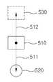
도 5는 본 발명에 따른 자율 주행 장치가 출발 위치에서 예측 지점을 산출하는 방법을 도시한 도면이다.5 is a diagram illustrating a method for calculating a prediction point at a starting position by the autonomous vehicle according to the present invention.
도 5를 참조하면, 초기 상태에서 목표물의 이동으로 본 발명에 따른 자율 주행 장치가 출발하는 경우에는 기존의 이동 정보 및 기존 위치에서 거리측정센서(110)가 측정한 거리, 방향추적부(120)가 산출한 방향정보는 없다. 이에 따라 이 동정보산출부(130)는 다음의 수학식 6에 의해 예측 지점을 산출한다.Referring to FIG. 5, when the autonomous driving device according to the present invention starts with the movement of a target in an initial state, the distance measured by the
여기서 V1은 본 발명에 따른 자율 주행 장치의 출발 위치(510)로부터 예측 지점(530)까지의 거리벡터(512)이고, V2는 출발 위치(510)로부터 목표물(520)까지의 거리 및 방향을 나타내는 거리벡터(511)이다. 거리벡터(511)는 출발 시 거리측정센서(110)가 측정한 거리, 방향추적부(120)가 산출한 방향정보를 통해 산출된다.Where V1 is the
이동정보산출부(130)는 산출된 거리벡터(413, 512)를 산출하여 예측 지점을 산정하고, 산출된 거리벡터(413, 511)의 크기 및 방향을 각각 산정된 예측지점으로 이동하기 위한 이동 정보로 산출한다. 즉 산출된 거리벡터(413, 512)의 크기는 예측지점과의 거리가 되고 산출된 거리벡터(413, 511)의 방향은 예측 지점으로 방향을 회전시키기 위한 회전 정보로 변환 된다.The motion
이동정보산출부(130)는 산출한 회전 정보를 기초로 각각의 모터의 개별 주행 속도를 산출하고 산출한 예측 지점과의 거리와 사전에 설정된 거리의 차이값을 기초로 주행 속도를 산출한다.The movement
이동정보산출부(130)는 현재 모터의 주행속도(V)에 방향정보(θ)에 따라 우륜 모터(150)와 좌륜 모터(160)의 각각의 개별 주행 속도(V1, V2)를 산출한다. 만일 방향정보가(θ)가 음의 값이면, 이동정보산출부(130)는 현재 모터의 주행속도(V)를 증가시켜 개별 주행 속도(V1)를 산출하고 현재 모터의 주행속도(V)를 감소시켜 개별 주행 속도(V2)를 산출한다. 방향정보(θ)가 '0'이면, 이동정보산출부(130)는 현재 모터의 주행속도(V)와 동일한 속도로 개별 주행 속도(V1)와 개별 주행 속도(V2)를 산출한다. 방향정보(θ)가 양의 값이면, 이동정보산출부(130)는 현재 모터의 주행속도(V)를 감소시켜 개별 주행 속도(V1)를 산출하고 현재 모터의 주행속도(V)를 증가시켜 개별 주행 속도(V2)를 산출한다. 이동정보산출부(130)는 개별 주행 속도의 산출시에 현재 모터의 주행속도(V)의 증가량과 감소량의 크기를 산출하는 일예로 다음의 수학식 7에 의해 산출한다.The movement

여기서 Δ는 증가량 또는 감소량의 절대값이다.Is the absolute value of the increase or decrease.
개별 주행 속도가 산출된 일예로 방향정보(θ)가 0이면 V1과V2는 V와 같은 값으로 산출되면, 다른 예로 방향정보(θ)가 -90이면 V1은 V2보다 5/3배 크다.For example, when the individual driving speed is calculated, when the direction information θ is 0, V1 and When V2 is calculated as the same value as V, in another example, when direction information θ is -90, V1 is 5/3 times larger than V2 .
다음으로 이동정보산출부(130)가 주행 속도(V')로 산출함에 있어서, 만일 거리측정센서(110)가 측정한 거리와 사전에 설정된 거리의 차이값이 동일하면 이동정보산출부(130)는 현재 모터의 주행 속도(V)를 그대로 주행 속도(V')로 산출한다. 여기서, 사전에 설정된 거리는 사용자에 의해 임의로 조절이 가능하다. 만일 차이값이 음수이면 이동정보산출부(130)는 현재 모터의 주행 속도(V)를 감소시켜 주행 속도(V')를 산출하고, 차이값이 양수이면 이동정보산출부(130)는 현재 모터의 주행 속도(V)를 증가시켜 주행 속도(V')를 산출한다. 이때, 증가량과 감소량의 절대값은 차이값의 절대값에 비례하여 결정되며, 일예로 다음의 수학식 8에 의해 구해진다.Next, when the moving

여기서 Λ는 증가량 또는 감소량의 절대값이고, T는 차이값의 절대값이며, a는 사람의 평균 걷는 속도를 실험적으로 측정하여 산출된 상수값이다.Here, Λ is the absolute value of the increase or decrease amount, T is the absolute value of the difference value, a is a constant value calculated by experimentally measuring the average walking speed of a person.
또한 이동 정보 산출부(130)는 클리프센서(180)가 측정한 바닥면과의 거리를 수신하여, 직전에 수신한 바닥면과의 거리의 차이를 구하여 바닥면과의 거리의 변화량을 산출한다. 상기 산출된 변화량이 사전에 설정된 값보다 크면 정지신호를 출력한다. 사전에 설정된 값은 제작자 또는 사용자에 의해 설정될 수 있으며, 일예로 구동륜(162, 164, 172, 174)의 크기의 10분 1로 설정된다.In addition, the movement
이동 정보 산출부(130)는 산출한 이동 정보 및 거리측정센서(110)가 측정한 거리, 방향추적부(120)가 산출한 방향정보를 메모리(140)에 저장한다. 즉 이동 정보 산출부(130)는 이동 정보인 회전 정보, 개별 주행 속도, 주행 속도를 메모리(140)에 저장하고 예측 지점을 산정할 때 메모리에 저장된 이동 정보를 기존의 이동 정보로 이용한다.The
제어부(150)는 이동정보산출부(130)가 산출한 이동 정보를 기초로 각각의 모터의 구동을 제어한다. 먼저 제어부(150)는 이동정보산출부(130)가 산출한 각각의 모터의 개별 주행 속도를 기초로 각각의 모터의 구동을 제어하여 방향을 회전시킨 다. 즉 제어부(150)는 각각의 개별 주행 속도(V1, V2)로 각각의 우륜 모터(150)와 좌륜 모터(160)의 회전수를 조절하여, 본 발명에 따른 자율 주행 장치의 정면이 송신기를 휴대한 목표물을 향하도록 방향을 회전시킨다.The
또한 제어부(150)는 목표물과 사전에 설정된 거리를 유지하도록 이동정보산출부(130)가 산출한 주행 속도(V')를 기초로 우륜 모터(150)와 좌륜 모터(160)의 구동을 제어한다. 즉 제어부(150)는 동일한 주행 속도(V')로 각각의 우륜 모터(150)와 좌륜 모터(160)의 회전수를 동일하게 조절하여 본 발명에 따른 자율 주행 장치가 목표물과 사전에 설정된 거리를 유지하며 이동하게 한다.In addition, the
또한 제어부(150)는 이동 정보 산출부(130)에 의해 출력된 정지신호를 수신하면 주행을 정지하도록 제어를 수행한다. 즉 제어부(150)는 제동장치(190)를 제어하여 구동륜(162, 164, 172, 174)의 구동을 멈추게 한다.In addition, the
우륜 모터(150)와 좌륜 모터(160)는 구동륜1, 구동륜2, 구동륜3, 구동륜4(170)를 회전시키기 위한 모터이며, 제어부(150)에 의해 그 구동이 제어된다. 여기서, 구동륜1, 구동륜2는 우륜 모터(150)에 의해 회전되면, 구동륜3, 구동륜4는 좌륜 모터(160)에 의해 회전된다.The
모터와 구동륜의 일실시 예로 구동륜1과 구동륜2는 무한괘도의 바퀴로 구성되고, 마찬가지로 구동륜3과 구동륜4도 무한괘도의 바퀴로 구성된다. 우륜 모터와 좌륜 모터는 각각 기어 박스를 통해서 구동륜1과 구동륜2, 구동륜3과 구동륜4에 회전동력을 전달한다. 이에 따라 모터의 토크를 최대한으로 이용하게 되어 본 발명에 따른 자율 주행 장치는 적은 동력으로도 25kg 하중을 갖는 물건을 운반할 수 있다.As an example of the motor and the driving wheel, the driving wheel 1 and the driving wheel 2 are composed of wheels of infinite magnitude, and similarly, the driving wheel 3 and the driving wheel 4 are also composed of infinite magnitude wheels. The right wheel motor and the left wheel motor respectively transmit rotational power to the driving wheel 1 and the driving wheel 2, the driving wheel 3 and the driving wheel 4 through the gear box. Accordingly, the torque of the motor is utilized to the maximum, and thus the autonomous driving device according to the present invention can carry an object having a 25 kg load with little power.
클리프센서(180)는 바닥면으로 적외선을 송신하고 송신된 적외선이 반사되어 되돌아오는데 걸린 시간을 기초로 바닥면과의 거리를 측정한다. 클리프센서(180)는 본 발명에 따른 자율 주행 장치의 하부에 설치되어, 사전에 설정된 시간간격으로 주기적으로 클리프센서(180)로부터 바닥면까지의 거리를 측정한다. 일예로 시간간격은 0.2초 단위로 설정되며 주행속도에 맞추어 측정주기가 변경된다. 클리프센서(180)가 측정한 바닥면과의 거리는 이동 정보 산출부(130)로 입력된다. 클리프센서(180) 통해서 바닥면이 계단이나 절벽으로 이루어졌을 때 주행을 정지시켜 추락을 방지할 수 있다.The
제동장치(190)는 구동륜(162, 164, 172, 174)의 구동을 정지시킨다. 즉 제어부(150)에 제어를 받아 구동륜(162, 164, 172, 174)의 구동을 정지시켜 본 발명에 따른 자율 주행 장치의 이동을 멈추게 한다.The
도 6은 본 발명에 따른 자율 주행 장치에 대한 바람직한 다른 실시예의 구성을 도시한 블록도이다.6 is a block diagram showing the configuration of another preferred embodiment of the autonomous driving apparatus according to the present invention.
도 6을 참조하면, 도 1을 참조하면, 본 발명에 따른 자율 주행 장치(600)는 거리측정센서(110), 방향추적부(120), 이동정보산출부(130), 메모리(140), 제어부(650), 우륜 모터(160), 좌륜 모터(170), 구동륜(662, 664, 672, 674), 클리프센서(180), 제동장치(190) 및 방향전환수단(680)을 구비한다.Referring to FIG. 6, referring to FIG. 1, the
도 6의 실시예의 거리측정센서(110), 방향추적부(120), 이동정보산출부(130), 메모리(140), 우륜 모터(160), 좌륜 모터(170), 클리프센서(180), 제동장 치(190)는 상술한 도 1의 실시예의 자율 주행 장치(100)의 거리측정센서(110), 방향추적부(120), 이동정보산출부(130), 메모리(140), 우륜 모터(160), 좌륜 모터(170), 클리프센서(180), 제동장치(190)와 대응되는 구성요소이다. 6, the
구동륜(662, 672)은 본 발명에 따른 자율 주행 장치의 앞바퀴를 의미하고 구동륜(664, 674)은 본 발명에 따는 자율 주행 장치의 뒷바퀴를 의미한다.The drive wheels 662 and 672 mean the front wheels of the autonomous driving device according to the present invention, and the drive wheels 664 and 674 mean the rear wheels of the autonomous driving device according to the present invention.
방향전환수단(680)은 구동륜(662, 672)을 회전시켜 본 발명에 따른 자율 주행 장치의 방향을 전환시킨다.The turning means 680 rotates the driving wheels 662 and 672 to change the direction of the autonomous driving device according to the present invention.
제어부(650)는 이동정보산출부(130)가 산출한 회전 정보를 기초로 방향전환수단(680)을 제어하여 본 발명에 따른 자율 주행 장치(600)의 방향을 전환시키고 이동정보산출부(130)가 산출한 주행 속도를 기초로 우륜 모터(160), 좌륜 모터(170)를 구동을 제어하여 본 발명에 따른 자율 주행 장치(600)가 예측 지점으로 이동하게 한다. 제어부(650)가 방향전환수단(680)을 제어하여 방향을 전환함으로써, 본 발명에 따른 자율 주행 장치(600)는 보다 신속하고 정확하게 예측 지점으로 방향을 전환할 수 있다.The
도 7은 본 발명에 따른 자율 주행 방법에 대한 바람직한 일 실시예의 수행 과정을 도시한 흐름도이다.7 is a flowchart illustrating a process of performing a preferred embodiment of the autonomous driving method according to the present invention.
도 7을 참조하면, 방향측정센서(122)는 목표물에 휴대된 송신기로부터 전송되는 무선신호를 수신한다(S700). 방향정보산출부(124)는 방향측정센서(122)가 수신한 무선신호를 기초로 방향정보를 산출한다(S710). 거리측정센서(110)는 목표물감지신호를 목표물에 송신하고 목표물로부터 반사된 목표물감지신호를 수신하여 목 표물과의 거리를 측정한다(S720). 여기서 목표물감지신호는 목표물에 의해 반사되는 특성이 있는 전파이며, 일예로 초음파가 있다. 이동정보산출부(130)는 거리측정센서(110)가 측정한 거리, 방향정보산출부(124)가 산출한 방향정보 및 기존의 회전 정보 및 주행 속도를 기초로 목표물의 이동 방향을 기준으로 목표물의 선두에 위치하는 예측 지점을 산정한다(S730). 다음으로 이동정보산출부(130)는 산출한 예측 지점으로 방향을 회전시키기 위한 회전 정보를 산출하고 산출한 회전 정보를 기초로 각각의 모터의 개별 주행 속도 및 본 발명에 따른 자율 주행 장치로부터 산출한 예측 지점과의 거리와 사전에 설정된 거리의 차이값을 기초로 주행 속도를 산출한다(S740). 여기서 이동정보산출부(130)는 산출한 회전 정보, 개별 주행 속도, 주행 속도, 거리측정센서(110)가 측정한 거리 및 방향정보산출부(124)가 산출한 방향정보를 메모리(40)에 저장한다.Referring to FIG. 7, the
제어부(150)는 이동정보산출부(130)가 산출한 각각의 모터의 개별 주행 속도를 기초로 우륜 모터(150)과 좌륜 모토(160)의 구동을 제어한다(S750). 다음으로 제어부(150)는 이동정보산출부(130)가 산출한 주행 속도를 기초로 우륜 모터(150)와 좌륜 모토(160)의 구동을 제어한다(S760).The
다음으로 클리프센서(180)는 바닥면으로 적외선을 송신하고 송신된 적외선이 반사되어 되돌아오는데 걸린 시간을 기초로 바닥면과의 거리를 측정한다(S770). 이동 정보 산출부(130)는 측정된 바닥면과의 거리와 종전에 측정된 바닥면과의 거리로부터 변화량을 산출하고 상기 산출된 변화량이 사전에 설정된 값보다 크면 정지신호를 출력한다(S780). 제어부(150)는 정지신호가 출력되면 주행을 정지하도록 제 어한다(S790).Next, the
도 8은 본 발명에 따른 자율 주행 방법에 대한 바람직한 다른 실시예의 수행 과정을 도시한 흐름도이다.8 is a flowchart illustrating a process of performing another preferred embodiment of the autonomous driving method according to the present invention.
도 8을 참조하면, 방향측정센서(122)는 목표물에 휴대된 송신기로부터 전송되는 무선신호를 수신한다(S800). 방향정보산출부(124)는 방향측정센서(122)가 수신한 무선신호를 기초로 방향정보를 산출한다(S810). 거리측정센서(110)는 목표물감지신호를 목표물에 송신하고 목표물로부터 반사된 목표물감지신호를 수신하여 목표물과의 거리를 측정한다(S820). 여기서 목표물감지신호는 목표물에 의해 반사되는 특성이 있는 전파이며, 일예로 초음파가 있다. 이동정보산출부(130)는 거리측정센서(110)가 측정한 거리, 방향정보산출부(124)가 산출한 방향정보 및 기존의 회전 정보 및 주행 속도를 기초로 목표물의 이동 방향을 기준으로 목표물의 선두에 위치하는 예측 지점을 산정한다(S830). 다음으로 이동정보산출부(130)는 산출한 예측 지점으로 방향을 회전시키기 위한 회전 정보를 산출하고 본 발명에 따른 자율 주행 장치로부터 산출한 예측 지점과의 거리와 사전에 설정된 거리의 차이값을 기초로 주행 속도를 산출한다(S840). 여기서 이동정보산출부(130)는 산출한 회전 정보, 주행 속도, 거리측정센서(110)가 측정한 거리 및 방향정보산출부(124)가 산출한 방향정보를 메모리(40)에 저장한다.Referring to FIG. 8, the
제어부(650)는 이동정보산출부(130)가 산출한 각각의 모터의 개별 주행 속도를 기초로 우륜 모터(150)와 좌륜 모토(160)의 구동을 제어한다(S850). 다음으로 제어부(150)는 이동정보산출부(130)가 산출한 주행 속도를 기초로 우륜 모터(150) 와 좌륜 모토(160)의 구동을 제어한다(S860).The
다음으로 클리프센서(180)는 바닥면으로 적외선을 송신하고 송신된 적외선이 반사되어 되돌아오는데 걸린 시간을 기초로 바닥면과의 거리를 측정한다(S870). 이동 정보 산출부(130)는 측정된 바닥면과의 거리와 종전에 측정된 바닥면과의 거리로부터 변화량을 산출하고 상기 산출된 변화량이 사전에 설정된 값보다 크면 정지신호를 출력한다(S880). 제어부(150)는 정지신호가 출력되면 주행을 정지하도록 제어한다(S890).Next, the
본 발명에 따른 자율 운반 장치는 거리측정센서, 방향측정센서, 방향정보산출부, 이동정보산출부, 제어부, 우륜 모터, 좌륜 모터, 구동륜, 클리프센서 및 제동장치를 구비한다. 본 발명에 따른 자율 운반 장치에 구비된 거리측정센서, 이동정보산출부, 제어부, 우륜 모터, 좌륜 모터, 구동륜, 클리프센서 및 제동장치는 각각 본 발명에 따른 자율 주행 장치에 구비된 각각의 거리측정센서(110), 이동정보산출부(130), 제어부(150), 우륜 모터(160), 좌륜 모터(170), 구동륜(162, 164, 172, 174), 클리프센서(180) 및 제동장치(190)와 대응하는 구성요소로, 구체적인 설명은 생략한다. 또한 본 발명에 따른 자율 운반 장치에 구비된 방향측정센서 및 방향정보산출부는 각각 본 발명에 따른 자율 주행 장치에 구비된 방향측정센서(122) 및 방향정보산출부(124)와 대응하는 구성요소로, 구체적인 설명은 생략한다.The autonomous transport apparatus according to the present invention includes a distance measuring sensor, a direction measuring sensor, a direction information calculating unit, a moving information calculating unit, a control unit, a right wheel motor, a left wheel motor, a driving wheel, a cliff sensor, and a braking device. The distance measuring sensor, the movement information calculation unit, the control unit, the right wheel motor, the left wheel motor, the driving wheel, the cliff sensor, and the braking device provided in the autonomous vehicle according to the present invention are respectively measured for each distance provided in the autonomous vehicle according to the present invention.
또한 본 발명에 따른 자율 운반 장치는 다른 일시예로 거리측정센서, 방향측정센서, 방향정보산출부, 이동정보산출부, 제어부, 우륜 모터, 좌륜 모터, 구동륜, 클리프센서, 제동장치 및 방향전환수단을 구비한다. 여기서 구동륜, 제어부, 방향전환수단을 본 발명에 따른 자율 운반 장치에 구비된 구동륜(662, 664, 672, 674), 제어부(650), 방향전환수단(680)과 대응하는 구성요소로, 구체적인 설명은 생략한다.In addition, the autonomous conveying device according to the present invention includes a distance measuring sensor, a direction measuring sensor, a direction information calculating unit, a moving information calculating unit, a control unit, a right wheel motor, a left wheel motor, a driving wheel, a cliff sensor, a braking device, and a direction switching means. It is provided. Here, the drive wheel, the control unit, the direction switching means as a component corresponding to the drive wheels 662, 664, 672, 674, the
본 발명은 또한 컴퓨터로 읽을 수 있는 기록매체에 컴퓨터가 읽을 수 있는 코드로서 구현하는 것이 가능하다. 컴퓨터가 읽을 수 있는 기록매체는 컴퓨터 장치에 의하여 읽혀질 수 있는 데이터가 저장되는 모든 종류의 기록장치를 포함한다. 컴퓨터가 읽을 수 있는 기록매체의 예로는 ROM, RAM, CD-ROM, 자기 테이프, 플로피디스크, 광데이터 저장장치 등이 있으며, 또한 캐리어 웨이브(예를 들어 인터넷을 통한 전송)의 형태로 구현되는 것도 포함한다. 또한 컴퓨터가 읽을 수 있는 기록매체는 네트워크로 연결된 컴퓨터 장치에 분산되어 분산방식으로 컴퓨터가 읽을 수 있는 코드가 저장되고 실행될 수 있다.The invention can also be embodied as computer readable code on a computer readable recording medium. The computer-readable recording medium includes all kinds of recording devices in which data that can be read by a computer device is stored. Examples of computer-readable recording media include ROM, RAM, CD-ROM, magnetic tape, floppy disk, optical data storage, and the like, and may also be implemented in the form of a carrier wave (for example, transmission over the Internet). Include. The computer readable recording medium can also be distributed over network coupled computer devices so that the computer readable code is stored and executed in a distributed fashion.
이상에서 본 발명의 바람직한 실시예에 대해 도시하고 설명하였으나, 본 발명은 상술한 특정의 바람직한 실시예에 한정되지 아니하며, 청구범위에서 청구하는 본 발명의 요지를 벗어남이 없이 당해 발명이 속하는 기술분야에서 통상의 지식을 가진 자라면 누구든지 다양한 변형 실시가 가능한 것은 물론이고, 그와 같은 변경은 청구범위 기재의 범위 내에 있게 된다.Although the preferred embodiments of the present invention have been shown and described above, the present invention is not limited to the specific preferred embodiments described above, and the present invention belongs to the present invention without departing from the gist of the present invention as claimed in the claims. Various modifications can be made by those skilled in the art, and such changes are within the scope of the claims.
도 1은 본 발명에 따른 자율 주행 장치에 대한 바람직한 일 실시예의 구성을 도시한 블록도,1 is a block diagram showing the configuration of a preferred embodiment of the autonomous driving apparatus according to the present invention;
도 2는 본 발명에 따른 방향측정센서의 배치에 대한 바람직한 일 실시예를 도시한 도면,Figure 2 shows a preferred embodiment of the arrangement of the orientation sensor according to the invention,
도 3은 각각의 방향측정센서(122)와 연관된 각도 정보를 산출하는 방법을 도시한 도면,3 illustrates a method of calculating angle information associated with each
도 4는 본 발명에 따른 자율 주행 장치가 예측 지점을 산출하는 방법을 도시한 도면,4 is a diagram illustrating a method for calculating a prediction point by the autonomous vehicle according to the present invention;
도 5는 본 발명에 따른 자율 주행 장치가 출발 위치에서 예측 지점을 산출하는 방법을 도시한 도면,5 is a diagram illustrating a method for calculating a prediction point at a starting position by the autonomous driving device according to the present invention;
도 6은 본 발명에 따른 자율 주행 장치에 대한 바람직한 다른 실시예의 구성을 도시한 블록도,6 is a block diagram showing the configuration of another preferred embodiment of the autonomous driving apparatus according to the present invention;
도 7은 본 발명에 따른 자율 주행 방법에 대한 바람직한 일 실시예의 수행 과정을 도시한 흐름도, 그리고,7 is a flowchart illustrating a process of performing a preferred embodiment of the autonomous driving method according to the present invention;
도 8은 본 발명에 따른 자율 주행 방법에 대한 바람직한 일 실시예의 수행 과정을 도시한 흐름도이다.8 is a flowchart illustrating a process of performing a preferred embodiment of the autonomous driving method according to the present invention.
Claims (15)
Translated fromKoreanPriority Applications (2)
| Application Number | Priority Date | Filing Date | Title |
|---|---|---|---|
| KR1020070081602AKR100860843B1 (en) | 2007-08-14 | 2007-08-14 | Autonomous driving device and method, and autonomous vehicle using same |
| PCT/KR2008/004709WO2009022859A2 (en) | 2007-08-14 | 2008-08-13 | Self traveling device and method and self carrying device using the same |
Applications Claiming Priority (1)
| Application Number | Priority Date | Filing Date | Title |
|---|---|---|---|
| KR1020070081602AKR100860843B1 (en) | 2007-08-14 | 2007-08-14 | Autonomous driving device and method, and autonomous vehicle using same |
Publications (1)
| Publication Number | Publication Date |
|---|---|
| KR100860843B1true KR100860843B1 (en) | 2008-09-29 |
Family
ID=40023868
Family Applications (1)
| Application Number | Title | Priority Date | Filing Date |
|---|---|---|---|
| KR1020070081602AExpired - Fee RelatedKR100860843B1 (en) | 2007-08-14 | 2007-08-14 | Autonomous driving device and method, and autonomous vehicle using same |
Country Status (2)
| Country | Link |
|---|---|
| KR (1) | KR100860843B1 (en) |
| WO (1) | WO2009022859A2 (en) |
Cited By (1)
| Publication number | Priority date | Publication date | Assignee | Title |
|---|---|---|---|---|
| KR102104747B1 (en) | 2019-05-10 | 2020-04-27 | 김하영 | An Artificial Intelligence Operating Type of a Carrier Apparatus Capable of Moving Automatically |
Families Citing this family (7)
| Publication number | Priority date | Publication date | Assignee | Title |
|---|---|---|---|---|
| US12084824B2 (en) | 2015-03-06 | 2024-09-10 | Walmart Apollo, Llc | Shopping facility assistance systems, devices and methods |
| WO2016142794A1 (en) | 2015-03-06 | 2016-09-15 | Wal-Mart Stores, Inc | Item monitoring system and method |
| US20180099846A1 (en) | 2015-03-06 | 2018-04-12 | Wal-Mart Stores, Inc. | Method and apparatus for transporting a plurality of stacked motorized transport units |
| US12366043B2 (en) | 2015-03-06 | 2025-07-22 | Walmart Apollo, Llc | Overriding control of motorized transport unit systems, devices and methods |
| US10358326B2 (en) | 2015-03-06 | 2019-07-23 | Walmart Apollo, Llc | Shopping facility assistance systems, devices and methods |
| CA2938589A1 (en)* | 2015-08-14 | 2017-02-14 | Wal-Mart Stores, Inc. | Shopping facility assistance systems, devices, and methods to facilitate responding to a user's request for product pricing information |
| CA2961938A1 (en) | 2016-04-01 | 2017-10-01 | Wal-Mart Stores, Inc. | Systems and methods for moving pallets via unmanned motorized unit-guided forklifts |
Citations (7)
| Publication number | Priority date | Publication date | Assignee | Title |
|---|---|---|---|---|
| JPH0217673A (en)* | 1988-07-06 | 1990-01-22 | Sony Corp | Semiconductor device and its manufacturing method |
| JPH062223A (en)* | 1991-06-07 | 1994-01-11 | N Schlumberger & Co | Card for wool |
| JP2007092001A (en)* | 2005-09-30 | 2007-04-12 | Dainippon Ink & Chem Inc | Liquid crystal display element |
| JP2007097004A (en)* | 2005-09-30 | 2007-04-12 | Alaxala Networks Corp | Network repeating device |
| JP2007090000A (en)* | 2005-09-30 | 2007-04-12 | Nippon Koden Corp | ECG data compression method and electrocardiogram telemeter device |
| JP2007098006A (en)* | 2005-10-07 | 2007-04-19 | Matsushita Electric Ind Co Ltd | Dehumidification system |
| JP2008004001A (en)* | 2006-06-26 | 2008-01-10 | Hitachi Omron Terminal Solutions Corp | Registration processing guidance apparatus and method of biometric authentication system |
Family Cites Families (3)
| Publication number | Priority date | Publication date | Assignee | Title |
|---|---|---|---|---|
| JPH05107331A (en)* | 1991-10-16 | 1993-04-27 | Sakuma Susumu | Transmission position detecting method using radio signal |
| KR100633160B1 (en)* | 2004-12-17 | 2006-10-11 | 삼성전자주식회사 | Robot system that can recognize position and direction using beacon |
| KR100645381B1 (en)* | 2005-08-31 | 2006-11-14 | 삼성광주전자 주식회사 | External charge return device and return method for robot cleaner |
- 2007
- 2007-08-14KRKR1020070081602Apatent/KR100860843B1/ennot_activeExpired - Fee Related
- 2008
- 2008-08-13WOPCT/KR2008/004709patent/WO2009022859A2/enactiveApplication Filing
Patent Citations (7)
| Publication number | Priority date | Publication date | Assignee | Title |
|---|---|---|---|---|
| JPH0217673A (en)* | 1988-07-06 | 1990-01-22 | Sony Corp | Semiconductor device and its manufacturing method |
| JPH062223A (en)* | 1991-06-07 | 1994-01-11 | N Schlumberger & Co | Card for wool |
| JP2007092001A (en)* | 2005-09-30 | 2007-04-12 | Dainippon Ink & Chem Inc | Liquid crystal display element |
| JP2007097004A (en)* | 2005-09-30 | 2007-04-12 | Alaxala Networks Corp | Network repeating device |
| JP2007090000A (en)* | 2005-09-30 | 2007-04-12 | Nippon Koden Corp | ECG data compression method and electrocardiogram telemeter device |
| JP2007098006A (en)* | 2005-10-07 | 2007-04-19 | Matsushita Electric Ind Co Ltd | Dehumidification system |
| JP2008004001A (en)* | 2006-06-26 | 2008-01-10 | Hitachi Omron Terminal Solutions Corp | Registration processing guidance apparatus and method of biometric authentication system |
Non-Patent Citations (7)
| Title |
|---|
| 공개특허 제1990-0007378호 |
| 공개특허 제1992-0011428호 |
| 공개특허 제1997-0049183호 |
| 공개특허 제1998-0069490호 |
| 공개특허 제2004-0015936호 |
| 등록특허 제0217673호 |
| 등록특허 제0602223호 |
Cited By (1)
| Publication number | Priority date | Publication date | Assignee | Title |
|---|---|---|---|---|
| KR102104747B1 (en) | 2019-05-10 | 2020-04-27 | 김하영 | An Artificial Intelligence Operating Type of a Carrier Apparatus Capable of Moving Automatically |
Also Published As
| Publication number | Publication date |
|---|---|
| WO2009022859A3 (en) | 2009-04-09 |
| WO2009022859A2 (en) | 2009-02-19 |
Similar Documents
| Publication | Publication Date | Title |
|---|---|---|
| KR100860843B1 (en) | Autonomous driving device and method, and autonomous vehicle using same | |
| KR102254881B1 (en) | A moving robot and a controlling method for the same | |
| KR102307220B1 (en) | Motion detection of autonomous vehicles using radar technology | |
| US8789638B2 (en) | Foldable cart with tracking arrangement | |
| JP7169593B2 (en) | Smart self-driving system with lateral following and obstacle avoidance | |
| US11630456B2 (en) | Autonomous travelling cart system | |
| US10271623B1 (en) | Smart self-driving systems with motorized wheels | |
| US9393981B1 (en) | Foldable cart with rear guidance arrangement | |
| AU2018101873A4 (en) | Ultra-wide band (UWB) based distance keeping system for autonomous mobile robot | |
| CN106575402A (en) | An intelligent shopping guide system | |
| WO2020124623A1 (en) | Intelligent motion system and method | |
| WO2020248185A1 (en) | Autonomous mobile robot with adjustable display screen | |
| EP3943366B1 (en) | Cart for stopping in parallel with installation and moving method | |
| US20210206416A1 (en) | Cart following transmission module based on position information of transmission module and method for moving thereof | |
| CN106997204A (en) | A kind of automatic following system based on ultrasonic wave | |
| US11511425B2 (en) | Robot stopping parallel to installed object and method of stopping the same | |
| JP2025022769A (en) | Transport vehicle travel control system and transport vehicle travel control method | |
| CN206906892U (en) | One kind follows dynamic structure and its system automatically | |
| WO2021240787A1 (en) | Underground exploration device | |
| KR102448856B1 (en) | Carrier and trolley management system that can track indoor location | |
| JP2013054544A (en) | Automatic follow-up type self-traveling carriage | |
| KR20200112490A (en) | Method and system for operating cart device | |
| JP7575832B1 (en) | Route generation system, route generation method, and program for a mobile object | |
| JP7548650B1 (en) | Mobile object route generation system, route generation method, and program | |
| JP7464331B1 (en) | Transport vehicle travel control system and transport vehicle travel control method |
Legal Events
| Date | Code | Title | Description |
|---|---|---|---|
| A201 | Request for examination | ||
| PA0109 | Patent application | St.27 status event code:A-0-1-A10-A12-nap-PA0109 | |
| PA0201 | Request for examination | St.27 status event code:A-1-2-D10-D11-exm-PA0201 | |
| A302 | Request for accelerated examination | ||
| PA0302 | Request for accelerated examination | St.27 status event code:A-1-2-D10-D17-exm-PA0302 St.27 status event code:A-1-2-D10-D16-exm-PA0302 | |
| E902 | Notification of reason for refusal | ||
| PE0902 | Notice of grounds for rejection | St.27 status event code:A-1-2-D10-D21-exm-PE0902 | |
| P11-X000 | Amendment of application requested | St.27 status event code:A-2-2-P10-P11-nap-X000 | |
| P13-X000 | Application amended | St.27 status event code:A-2-2-P10-P13-nap-X000 | |
| E90F | Notification of reason for final refusal | ||
| PE0902 | Notice of grounds for rejection | St.27 status event code:A-1-2-D10-D21-exm-PE0902 | |
| P11-X000 | Amendment of application requested | St.27 status event code:A-2-2-P10-P11-nap-X000 | |
| P13-X000 | Application amended | St.27 status event code:A-2-2-P10-P13-nap-X000 | |
| E701 | Decision to grant or registration of patent right | ||
| PE0701 | Decision of registration | St.27 status event code:A-1-2-D10-D22-exm-PE0701 | |
| GRNT | Written decision to grant | ||
| PR0701 | Registration of establishment | St.27 status event code:A-2-4-F10-F11-exm-PR0701 | |
| R18-X000 | Changes to party contact information recorded | St.27 status event code:A-5-5-R10-R18-oth-X000 | |
| PR1002 | Payment of registration fee | St.27 status event code:A-2-2-U10-U11-oth-PR1002 Fee payment year number:1 | |
| PG1601 | Publication of registration | St.27 status event code:A-4-4-Q10-Q13-nap-PG1601 | |
| R18-X000 | Changes to party contact information recorded | St.27 status event code:A-5-5-R10-R18-oth-X000 | |
| LAPS | Lapse due to unpaid annual fee | ||
| PC1903 | Unpaid annual fee | St.27 status event code:A-4-4-U10-U13-oth-PC1903 Not in force date:20110924 Payment event data comment text:Termination Category : DEFAULT_OF_REGISTRATION_FEE | |
| PC1903 | Unpaid annual fee | St.27 status event code:N-4-6-H10-H13-oth-PC1903 Ip right cessation event data comment text:Termination Category : DEFAULT_OF_REGISTRATION_FEE Not in force date:20110924 | |
| P22-X000 | Classification modified | St.27 status event code:A-4-4-P10-P22-nap-X000 | |
| P22-X000 | Classification modified | St.27 status event code:A-4-4-P10-P22-nap-X000 | |
| P22-X000 | Classification modified | St.27 status event code:A-4-4-P10-P22-nap-X000 |