KR100859718B1 - Dipole tag antenna mountable on metallic objects using artificial magnetic conductorAMC for wireless identification and wireless identification system using the same dipole tag antenna - Google Patents
Dipole tag antenna mountable on metallic objects using artificial magnetic conductorAMC for wireless identification and wireless identification system using the same dipole tag antennaDownload PDFInfo
- Publication number
- KR100859718B1 KR100859718B1KR1020070019904AKR20070019904AKR100859718B1KR 100859718 B1KR100859718 B1KR 100859718B1KR 1020070019904 AKR1020070019904 AKR 1020070019904AKR 20070019904 AKR20070019904 AKR 20070019904AKR 100859718 B1KR100859718 B1KR 100859718B1
- Authority
- KR
- South Korea
- Prior art keywords
- tag antenna
- artificial magnetic
- magnetic conductor
- dipole tag
- wireless recognition
- Prior art date
- Legal status (The legal status is an assumption and is not a legal conclusion. Google has not performed a legal analysis and makes no representation as to the accuracy of the status listed.)
- Expired - Fee Related
Links
Images


Classifications
- F—MECHANICAL ENGINEERING; LIGHTING; HEATING; WEAPONS; BLASTING
- F16—ENGINEERING ELEMENTS AND UNITS; GENERAL MEASURES FOR PRODUCING AND MAINTAINING EFFECTIVE FUNCTIONING OF MACHINES OR INSTALLATIONS; THERMAL INSULATION IN GENERAL
- F16H—GEARING
- F16H55/00—Elements with teeth or friction surfaces for conveying motion; Worms, pulleys or sheaves for gearing mechanisms
- F16H55/02—Toothed members; Worms
- F16H55/14—Construction providing resilience or vibration-damping
- H—ELECTRICITY
- H01—ELECTRIC ELEMENTS
- H01Q—ANTENNAS, i.e. RADIO AERIALS
- H01Q1/00—Details of, or arrangements associated with, antennas
- H01Q1/12—Supports; Mounting means
- H01Q1/22—Supports; Mounting means by structural association with other equipment or articles
- H01Q1/2208—Supports; Mounting means by structural association with other equipment or articles associated with components used in interrogation type services, i.e. in systems for information exchange between an interrogator/reader and a tag/transponder, e.g. in Radio Frequency Identification [RFID] systems
- H01Q1/2225—Supports; Mounting means by structural association with other equipment or articles associated with components used in interrogation type services, i.e. in systems for information exchange between an interrogator/reader and a tag/transponder, e.g. in Radio Frequency Identification [RFID] systems used in active tags, i.e. provided with its own power source or in passive tags, i.e. deriving power from RF signal
- F—MECHANICAL ENGINEERING; LIGHTING; HEATING; WEAPONS; BLASTING
- F16—ENGINEERING ELEMENTS AND UNITS; GENERAL MEASURES FOR PRODUCING AND MAINTAINING EFFECTIVE FUNCTIONING OF MACHINES OR INSTALLATIONS; THERMAL INSULATION IN GENERAL
- F16H—GEARING
- F16H55/00—Elements with teeth or friction surfaces for conveying motion; Worms, pulleys or sheaves for gearing mechanisms
- F16H55/02—Toothed members; Worms
- F16H55/17—Toothed wheels
- H—ELECTRICITY
- H01—ELECTRIC ELEMENTS
- H01Q—ANTENNAS, i.e. RADIO AERIALS
- H01Q15/00—Devices for reflection, refraction, diffraction or polarisation of waves radiated from an antenna, e.g. quasi-optical devices
- H01Q15/0006—Devices acting selectively as reflecting surface, as diffracting or as refracting device, e.g. frequency filtering or angular spatial filtering devices
- H01Q15/006—Selective devices having photonic band gap materials or materials of which the material properties are frequency dependent, e.g. perforated substrates, high-impedance surfaces
- H01Q15/008—Selective devices having photonic band gap materials or materials of which the material properties are frequency dependent, e.g. perforated substrates, high-impedance surfaces said selective devices having Sievenpipers' mushroom elements
- H—ELECTRICITY
- H01—ELECTRIC ELEMENTS
- H01Q—ANTENNAS, i.e. RADIO AERIALS
- H01Q9/00—Electrically-short antennas having dimensions not more than twice the operating wavelength and consisting of conductive active radiating elements
- H01Q9/04—Resonant antennas
- H01Q9/16—Resonant antennas with feed intermediate between the extremities of the antenna, e.g. centre-fed dipole
- H01Q9/28—Conical, cylindrical, cage, strip, gauze, or like elements having an extended radiating surface; Elements comprising two conical surfaces having collinear axes and adjacent apices and fed by two-conductor transmission lines
- H01Q9/285—Planar dipole
Landscapes
- Engineering & Computer Science (AREA)
- General Engineering & Computer Science (AREA)
- Mechanical Engineering (AREA)
- Physics & Mathematics (AREA)
- Optics & Photonics (AREA)
- Details Of Aerials (AREA)
- Variable-Direction Aerials And Aerial Arrays (AREA)
Abstract
Translated fromKoreanDescription
Translated fromKorean도 1a 및 1b는 종래의 안테나에 적용된 인공자기도체에 대한 측면도 및 사시도이다.1A and 1B are side and perspective views of an artificial magnetic conductor applied to a conventional antenna.
도 2는 본 발명의 일 실시예에 따른 인공자기도체를 이용한 다이폴 태그 안테나에 대한 평면도이다.2 is a plan view of a dipole tag antenna using an artificial magnetic conductor according to an embodiment of the present invention.
도 3은 도 2의 인공자기도체를 이용한 다이폴 태그 안테나의 다이폴 태그 안테나를 좀더 상세하게 보여주는 평면도이다.3 is a plan view illustrating in more detail a dipole tag antenna of a dipole tag antenna using the artificial magnetic conductor of FIG. 2.
도 4a 및 4b는 도 2의 인공자기도체를 이용한 다이폴 태그 안테나에 적용할 수 있는 인공자기도체의 단위 셀 패턴에 대한 평면도들이다.4A and 4B are plan views illustrating a unit cell pattern of an artificial magnetic conductor that can be applied to a dipole tag antenna using the artificial magnetic conductor of FIG. 2.
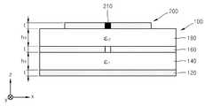
도 5는 도 2의 인공자기도체를 이용한 다이폴 태그 안테나에 대한 측면도이다.FIG. 5 is a side view of a dipole tag antenna using the artificial magnetic conductor of FIG. 2.
도 6은 도 2의 인공자기도체의 단위 셀의 한 변의 길이변화에 대한 안테나의 주파수 특성을 보여주는 그래프이다.FIG. 6 is a graph showing frequency characteristics of an antenna with respect to a length change of one side of a unit cell of the artificial magnetic conductor of FIG. 2.
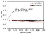
도 7은 도 2의 인공자기도체를 이용한 다이폴 태그 안테나의 RCS와 인식거리 특성을 보여주는 그래프이다.FIG. 7 is a graph illustrating RCS and recognition distance characteristics of a dipole tag antenna using the artificial magnetic conductor of FIG. 2.
<도면에 주요부분에 대한 설명><Description of main parts in the drawing>
100: 인공자기도체 120: 접지층100: artificial magnetic conductor 120: ground layer
140: 기판 160: 인공자기도체층140: substrate 160: artificial magnetic conductor layer
140a: 유전체층 160a: 도전체층140a:
180: 제2 유전체층 200: 다이폴 태그 안테나180: second dielectric layer 200: dipole tag antenna
210: 무선 인식용 칩 220, 240: 도체판210: chip for
260: 연결부260: connection
본 발명은 안테나 및 안테나를 이용한 무선인식 시스템에 관한 것으로서, 특히 인공자기도체를 이용한 태그 안테나 및 그 태그 안테나를 이용한 무선인식 시스템에 관한 것이다.The present invention relates to an antenna and a wireless recognition system using an antenna, and more particularly, to a tag antenna using an artificial magnetic conductor and a wireless recognition system using the tag antenna.
자기도체(magnetic conductor)는 일반적으로 사용되는 전기도체(electric conductor)에 상응하는 것으로, 전기도체의 표면상에서는 전기장의 접선 성분이 거의 0이 되지만, 자기도체의 표면상에서는 자기장의 접선 성분이 거의 0이 되어 전기도체에서와는 달리 자기도체 표면상으로는 전류가 흐를 수 없게 된다.Magnetic conductors correspond to commonly used electrical conductors, where the tangent component of the electric field is almost zero on the surface of the electric conductor, but the tangent component of the magnetic field is almost zero on the surface of the magnetic conductor. This prevents current from flowing on the surface of the magnetic conductor, unlike electrical conductors.
이와 같은 자기도체의 성질로 인하여, 자기도체는 회로적으로는 특정 주파수 에서 상당히 높은 저항을 갖는 즉, 개방 회로의 기능을 하는 성분으로 작용하게 된다. 이러한 자기도체는 일반적인 전기도체 상에 의도된 특정 단위 셀 패턴을 일정 간격으로 주기적으로 배열함으로써, 구현할 수 있는데, 이렇게 만들어진 자기도체를 인공자기도체(Artificial Magnetic Conductor:AMC)라 한다.Due to such a property of the magnetic conductor, the magnetic conductor becomes a component that functions as an open circuit, that is, the circuit has a fairly high resistance at a specific frequency. Such a magnetic conductor may be realized by periodically arranging specific unit cell patterns intended on a general electric conductor at regular intervals. The magnetic conductor thus produced is called an artificial magnetic conductor (AMC).
인공자기도체의 표면은 전술한 바와 같이 회로적으로 고임피던스 표면(High Impedance Surface: HIS) 특성을 가지게 되는데, 이러한 인공자기도체의 HIS 특성은 형성된 인공자기도체 패턴에 따라, 특정 주파수에 의존하게 된다.As described above, the surface of the artificial magnetic conductor has a high impedance surface (HIS) characteristic, and the HIS characteristic of the artificial magnetic conductor is dependent on a specific frequency according to the formed artificial magnetic conductor pattern. .
한편, 일반적으로 안테나는 전기도체 접지면 위에서 송수신되는 신호 파장(λ)의 1/4 이상의 거리를 필요로 한다. 왜냐하면, λ/4 보다 가까운 거리에 있게 되면 안테나에 흐르는 전류와 반대 방향의 표면 전류가 전기도체 접지면 표면에서 유기됨으로써, 그 두 전류가 서로 상쇄되고 그에 따라 안테나가 제대로 동작할 수 없게 되기 때문이다. 그러나 인공자기도체는 표면으로 전류가 흐르지 않기 때문에 안테나는 전기도체 위에서보다 인공자기도체 위에서 훨씬 더 가까운 거리에서 동작할 수 있고, 그에 따라 접지면과 안테나 사이의 거리를 줄일 수 있는 장점이 있다.On the other hand, in general, the antenna needs a distance of 1/4 or more of the signal wavelength (λ) transmitted and received on the electrical conductor ground plane. This is because if the distance is closer than λ / 4, the surface current in the opposite direction to the current flowing through the antenna is induced at the surface of the electric conductor ground plane, so that the two currents cancel each other and the antenna cannot operate properly. . However, since the artificial magnetic conductor does not flow current to the surface, the antenna can operate at a much closer distance on the artificial magnetic conductor than on the electric conductor, thereby reducing the distance between the ground plane and the antenna.
현재 RFID와 같은 무선인식 시스템의 태그 안테나 개발 분야에서는 도체에 부착하여 활용 가능한 태그와 물과 같은 고유전체상에서 사용 가능한 태그에 대한 관심이 점점 증가하고 있다. 일반 태그 안테나들은 도체 상에 붙였을 때, 위에서 지적했던 대로 안테나로서 동작을 할 수 없지만 인공자기도체를 응용한 태그 안테나는 자동차나 컨테이너 박스 등의 도체에 부착하여 충분히 활용될 수 있다. 이는 무선인식 시스템의 활용 범위를 넓히는 것이라 할 수 있다.At present, in the field of tag antenna development of radio recognition system such as RFID, there is a growing interest in tags that can be attached to conductors and used on high dielectric materials such as water. When the general tag antennas are attached to a conductor, they cannot operate as antennas as pointed out above. However, tag antennas using artificial magnetic conductors can be fully utilized by attaching to conductors such as automobiles or container boxes. This can be said to expand the range of use of the wireless recognition system.
도 1a 및 1b는 종래의 안테나에 적용된 인공자기도체에 대한 측면도 및 사시도로서, 이에 대한 자세한 내용은 미국특허번호 제6768476호(특허일: 2004. 06. 27)에 개시되어 있다.1A and 1B are side and perspective views of an artificial magnetic conductor applied to a conventional antenna, and details thereof are disclosed in US Patent No. 6,68,476 (Patent Date: June 27, 2004).
도 1a를 참조하면, 인공자기도체(10)는 접지층(18), 제1 유전체층(14), 인공자기도체(12) 및 주파수 선택 표면층(22, Frequency Selective Surface(FSS) layer)을 포함한다.Referring to FIG. 1A, the artificial
인공자기도체(12)는 비아(16, via)를 통해 접지층(26)과 연결되고, FSS층(22)은 접지층(26) 및 전원으로 연결되어 커패시터(24)를 형성하게 된다.The artificial
도 1b는 도 1a에 대한 사시도로서, 도시한 바와 같이 인공자기도체(12)의 패턴은 단순 사각 패치로 배열(array) 형태를 이루고 있고, 각 사각 패치의 인공자기도체는 금속 비아(16)를 통해 접지층(18)으로 전기적으로 연결되는 구조로 형성된다. 이러한 인공자기도체(12) 패턴 상으로 모노 폴 타입의 안테나(미도시)가 실장되게 되는데, 안테나의 길이를 줄이기 위해 FSS층(22)이 커패시티브 로딩된 구조를 갖는다.FIG. 1B is a perspective view of FIG. 1A, in which the pattern of the artificial
한편, 제1 유전체층(14)이 송수신 신호 파장(λ)의 거의 1/50의 수준으로 형성되고 있음을 확인할 수 있는데, 이와 같이 인공자기도체를 이용함으로써 종래 안테나에 요구되었던 접지층으로부터 송수신 파장의 1/4 이상의 거리 간격이 불필요하게 되었음을 알 수 있다.On the other hand, it can be seen that the
도 1과 같은 종래의 인공자기도체를 이용한 안테나는 인공자기도체를 위한 비아를 포함하고, 또한 인공자기도체 상으로 실장되는 모노폴 안테나와 같은 안테 나가 실장되는데, 이러한 모노폴 안테나는 급전 포트로부터 전원을 공급받아 동작하는 구조를 갖는다. 따라서, 종래의 인공자기도체를 이용한 안테나는 비아를 필수적으로 포함함으로써, 인공자기도체의 형성 면에서도 복잡하고, 또한 전원 공급을 위한 급전 포트를 포함함으로써, 구조 및 사이즈 면에서 불리하다.The antenna using the conventional artificial magnetic conductor as shown in FIG. 1 includes vias for the artificial magnetic conductor, and also includes an antenna such as a monopole antenna mounted on the artificial magnetic conductor, which monopole antenna supplies power from a feed port. It has a structure that operates by receiving. Therefore, the antenna using a conventional artificial magnetic conductor is essentially complicated in the formation of the artificial magnetic conductor, and also includes a feed port for power supply, which is disadvantageous in structure and size.
따라서, 본 발명이 이루고자 하는 기술적 과제는 종래의 인공자기도체를 이용한 분야와는 전혀 다른 분야인 무선인식 시스템 분야에 인공자기도체를 적용하여 종래의 무선인식 시스템에서 태그가 갖는 구조적 문제점을 개선하고, 도체 상에 바로 부착하여 사용할 수 있고, 단순한 평판 구조로서 제작 및 비용면에서 저렴하며, 급전 포트가 불필요한 무선 인식용 칩을 포함하는 인공자기도체를 이용한 무선 인식용 다이폴 태그 안테나 및 그 다이폴 태그 안테나를 이용한 무선 인식 시스템을 제공하는 데에 있다.Therefore, the technical problem to be achieved by the present invention is to improve the structural problems of the tag in the conventional wireless recognition system by applying the artificial magnetic conductor to the field of the wireless recognition system which is a completely different field than the field using the conventional artificial magnetic conductor, A dipole tag antenna and a dipole tag antenna for wireless recognition using an artificial magnetic conductor, which can be directly attached onto a conductor, can be used in a simple flat structure, and is inexpensive to manufacture and cost, and includes a wireless recognition chip that does not need a feed port. It is to provide a wireless recognition system used.
상기 기술적 과제를 달성하기 위하여, 본 발명은 제1 유전체로 형성된 기판; 상기 기판 하부에 형성된 도전성의 접지층(ground layer); 상기 기판 상에 형성된 인공자기도체층(artificial magnetic conductor(AMC) layer); 및 상기 인공자기도체층 상에 부착되고 무선 인식용 칩을 구비한 다이폴 태그 안테나;를 포함하고, 도체 상에 바로 부착하여 사용할 수 있는 인공자기도체를 이용한 무선 인식용 다이폴 태그 안테나를 제공한다.In order to achieve the above technical problem, the present invention is a substrate formed of a first dielectric; A conductive ground layer formed under the substrate; An artificial magnetic conductor (AMC) layer formed on the substrate; And a dipole tag antenna attached to the artificial magnetic conductor layer and having a chip for wireless recognition, and providing a dipole tag antenna for wireless recognition using an artificial magnetic conductor that can be directly attached and used on a conductor.
본 발명에 있어서, 상기 무선 인식용 다이폴 태그 안테나는 전체적으로 평판 형 구조를 가짐으로써, 도체 상에 바로 부착이 용이하다. 또한, 상기 인공자기도체층은 사각 패치 형태의 단위 셀이 서로 일정 간격을 가지고 배열된 패턴으로 형성될 수 있다. 예컨대, 상기 인공자기도체층은 상기 직사각형 형태의 단위 셀을 8개 가지며, 상기 단위 셀은 2열 종대형으로 상기 기판 상에 배치되되, 1열당 4개의 단위 셀이 동일한 제1 간격으로 배치되고, 열 사이는 제2 간격을 가질 수 있다. 이와 같은 상기 단위 셀의 한 변의 길이의 변화에 따라 상기 다이폴 태그 안태나의 주파수 특성 및 인식거리 성능이 변화될 수 있다.In the present invention, the wireless recognition dipole tag antenna has a flat plate structure as a whole, so that it is easily attached onto the conductor. In addition, the artificial magnetic conductor layer may be formed in a pattern in which the unit cells of the rectangular patch shape are arranged at a predetermined interval from each other. For example, the artificial magnetic conductor layer has eight unit cells having the rectangular shape, and the unit cells are arranged on the substrate in a two-column vertical type, and four unit cells per column are arranged at the same first intervals. In between may have a second interval. As the length of one side of the unit cell changes, the frequency characteristic and the recognition distance performance of the dipole tag antenna may change.
한편, 상기 무선 인식용 칩은 수신되는 전자파에 의해 동작할 수 있는데, 상기 다이폴 태그 안테나는 '∽' 형태를 가지며, 상기 무선 인식용 칩은 상기 다이폴 태그 안테나의 중심부분에 배치될 수 있다. 예컨대, 상기 다이폴 태그 안테나는 한 변으로 개구부를 갖는 장방형의 두 도체판이 개구부를 통해 마주보며, 상기 두 도체판은 상기 연결부를 통해 연결되어 상기 '∽' 형태를 이룰 수 있다. 또한, 상기 연결부는 상기 개구부 내부로 삽입되는 형태로 상기 두 도체판과 연결되어 상기 개구부에 슬롯(slot)이 형성될 수도 있다. 이러한, 상기 두 도체판 각각의 변의 길이 및 상기 슬롯의 길이와 폭의 변화에 의하여 상기 다이폴 태그 안테나의 공진 주파수가 조절될 수 있다.On the other hand, the chip for wireless recognition may operate by the received electromagnetic waves, the dipole tag antenna has a '∽' shape, the chip for wireless recognition may be disposed in the central portion of the dipole tag antenna. For example, in the dipole tag antenna, two rectangular plates having openings on one side thereof face each other through the openings, and the two conductive plates may be connected to each other to form the '∽' shape. In addition, the connecting portion may be inserted into the opening to be connected to the two conductive plates so that a slot may be formed in the opening. The resonant frequency of the dipole tag antenna may be adjusted by changing lengths of sides of the two conductive plates and lengths and widths of the slots.
본 발명에 있어서, 상기 다이폴 태그 안테나는 상기 접지층과 송수신 전자파 파장의 1/4 이하의 간격을 가지고 상기 인공자기도체층 상에 부착될 수 있으며, 기판의 경우 에폭시로 형성될 수 있다.In the present invention, the dipole tag antenna may be attached on the artificial magnetic layer having a gap of 1/4 or less of the wavelength of the transmission and reception electromagnetic waves, the substrate may be formed of epoxy.
본 발명은 또한 상기 기술적 과제를 달성하기 위하여, 무선인식용 다이폴 태 그 안테나를 이용하여 제작된 무선인식 시스템을 제공한다.The present invention also provides a radio recognition system manufactured using a radio recognition dipole tag antenna in order to achieve the above technical problem.
본 발명에 있어서, 상기 인공자기도체층은 사각 패치 형태의 단위 셀이 서로 일정 간격을 가지고 배열된 패턴으로 형성될 수 있다.In the present invention, the artificial magnetic conductor layer may be formed in a pattern in which unit cells having a rectangular patch form are arranged at a predetermined interval from each other.
한편, 상기 무선 인식용 칩은 수신되는 전자파에 의해 동작하며, 상기 다이폴 태그 안테나는 '∽' 형태를 가지며, 상기 무선 인식용 칩은 상기 다이폴 태그 안테나의 중심부분에 배치될 수 있다. 예컨대, 상기 무선인식 시스템은 RFID(Radio Frequency Identification) 시스템일 수 있다.On the other hand, the chip for wireless recognition is operated by the received electromagnetic waves, the dipole tag antenna has a '∽' shape, the chip for wireless recognition may be disposed in the central portion of the dipole tag antenna. For example, the radio recognition system may be a radio frequency identification (RFID) system.
본 발명에 따른 인공자기도체를 이용한 무선 인식용 다이폴 태그 안테나는 급전 포트 필요없는 무선 인식용 칩을 내장하여 입사파에 의한 전자기적 상호작용에 의해 태그 안테나로서 동작할 수 있다. 또한, 평판형의 인공자기도체를 구조를 이용하여 자동차나 컨테이너 등의 도체에 바로 부착하여 사용할 수 있으므로 다양한 분야의 무선인식 시스템에 적용할 수 있다. 한편, 인공자기도체를 비아 없이 단순한 평판형으로 제작할 수 있으므로 제작 단가 면에서도 유리하고, 인공자기도체의 패턴 및 다이폴 태그 안테나의 구조를 조절함으로써 안테나의 인식거리를 비약적으로 확대할 수 있다.The dipole tag antenna for wireless recognition using an artificial magnetic conductor according to the present invention may operate as a tag antenna by electromagnetic interaction due to incident waves by embedding a chip for wireless recognition that does not require a power supply port. In addition, since the plate-shaped artificial magnetic conductor can be directly attached to a conductor such as a car or a container using a structure, it can be applied to a wireless recognition system of various fields. On the other hand, since the artificial magnetic conductor can be manufactured in a simple flat form without vias, it is advantageous in terms of manufacturing cost, and the recognition distance of the antenna can be dramatically increased by adjusting the pattern of the artificial magnetic conductor and the structure of the dipole tag antenna.
이하에서는 첨부된 도면을 참조하여 본 발명의 바람직한 실시예를 상세히 설명한다. 이하의 설명에서 어떤 구성 요소가 다른 구성 요소의 상부에 존재한다고 기술될 때, 이는 다른 구성 요소의 바로 위에 존재할 수도 있고, 그 사이에 제3의 구성 요소가 개재될 수도 있다. 또한, 도면에서 각 구성 요소의 두께나 크기는 설명의 편의 및 명확성을 위하여 과장되었고, 설명과 관계없는 부분은 생략되었다. 도면상에서 동일 부호는 동일한 요소를 지칭한다. 한편, 사용되는 용어들은 단지 본 발명을 설명하기 위한 목적에서 사용된 것이지 의미 한정이나 특허청구범위에 기재된 본 발명의 범위를 제한하기 위하여 사용된 것은 아니다.Hereinafter, with reference to the accompanying drawings will be described a preferred embodiment of the present invention; In the following description, when a component is described as being on top of another component, it may be directly on top of another component, and a third component may be interposed therebetween. In addition, in the drawings, the thickness or size of each component is exaggerated for convenience and clarity of description, and parts irrelevant to the description are omitted. Like numbers refer to like elements in the figures. On the other hand, the terms used are used only for the purpose of illustrating the present invention and are not used to limit the scope of the invention described in the meaning or claims.
도 2는 본 발명의 일 실시예에 따른 인공자기도체를 이용한 다이폴 태그 안테나에 대한 평면도이다.2 is a plan view of a dipole tag antenna using an artificial magnetic conductor according to an embodiment of the present invention.
도 2a를 참조하면, 인공자기도체를 이용한 다이폴 태그 안테나는 인공자기도체(100) 및 인공자기도체(100) 상에 부착된 다이폴 태그 안테나(200)를 포함한다.Referring to FIG. 2A, the dipole tag antenna using the artificial magnetic conductor includes an artificial
인공자기도체(100)는 도전성의 접지층(미도시), 제1 유전체로 형성된 기판(140) 및 인공자기도체층(160)을 포함한다. 인공자기도체층(160)은 도전성 물질로 일정한 패턴을 가지고 배열되는데, 본 실시예에서는 사각 패치 형태의 도체판이 일정 간격을 두고 2열 종대형으로 배치되어 있다. 본 실시예에서 사각 패치 형태로 2열 종대형으로 인공자기도체층(160) 패턴이 형성되었지만 인공자기도체층(160)의 패턴이 이에 한정되는 것은 아니다.The artificial
한편, 본 실시예의 인공자기도체(100)는 인공자기도체층(160)과 도전성 접지층(120)을 연결하는 비아가 필요 없으므로 제조 면에서도 간편하다. 그러나 본 실시예와 같이 비아가 없는 인공자기도체(100)에 한정되지 않고 필요에 따라 비아를 포함하는 구조로 형성할 수도 있음은 물론이다.On the other hand, since the artificial
인공자기도체층(160) 상부로 다이폴 태그 안테나(200)가 배치되는데, 인공자기도체층(160)에 바로 다이폴 태그 안테나(200)가 부착될 수도 있지만, 일반적으로는 인공자기도체층(160) 상에 형성된 제2 유전체층(미도시) 상에 부착된다. 이러한 제2 유전체층(미도시)은 공기와 비슷한 유전율을 가진 폼(foam)으로 형성될 수 있다.The
다이폴 태그 안테나(200)는 중심으로 일정부분이 비어있는 사각 패치 형태의 두 개의 도체판(220, 240)이 연결부(260)를 통해 연결되어 전체적으로 '∽'는 구조로 형성된다. 한편, 연결부(260) 중앙부로 급전 포트가 필요없는 무선 인식용 칩(210)이 배치된다. 즉, 이러한 무선 인식용 칩(210)은 전원을 통해 공급되는 에너지를 이용하는 것이 아니라 안테나로 입사되는 전자파의 에너지를 이용하여 동작하게 된다.In the
연결부(260)와 각 도체판(220, 240)은 슬롯(slot)을 형성하면서 연결되는데, 이러한 슬롯의 존재에 의해 안테나의 주파수 특성이 변경될 수 있다. 이하, 도체판(220, 240), 연결부(260) 및 슬롯들의 사이즈에 대한 내용은 도 3의 부분에서 설명한다.The connecting
일반적으로 인공자기도체를 이용하여 안테나를 구성하게 되면, 전체 안테나의 구조를 평판형으로 형성할 수 있고, 또한 전기도체 접지면으로부터 λ/4 이상의 간격이 요구되지 않으므로 안테나의 전체 사이즈를 감소시킬 수 있다. 또한, 인공자기도체를 이용하는 경우 공진 주파수에서 반사파 위상 변화가 작으므로, 즉 전기도체와는 반대로 안테나로부터의 방사된 전파가 자기도체를 맞고 동위상으로 반사되기 때문에 전기도체가 있을 때보다 이론적으로 약 3dB 이득 향상을 가질 수 있다. 한편, 평판형(low-profile)으로 제작되어 차량이나 컨테이너 등의 금속 도체 표면에 바로 부착하여 사용할 수 있다는 장점도 가진다.In general, when the antenna is constructed using an artificial magnetic conductor, the entire antenna structure can be formed in a flat plate shape, and since the spacing of λ / 4 or more from the electrical conductor ground plane is not required, the overall size of the antenna can be reduced. have. In addition, when the artificial magnetic conductor is used, since the reflected wave phase change is small at the resonance frequency, that is, as opposed to the electrical conductor, the radiated radio waves from the antenna hit the magnetic conductor and are reflected in phase, which is theoretically weaker than that of the electric conductor. It can have a 3dB gain improvement. On the other hand, it has the advantage that it can be directly attached to the surface of a metal conductor such as a vehicle or a container is manufactured in a low-profile.
도 3은 도 2의 인공자기도체를 이용한 다이폴 태그 안테나의 다이폴 태그 안테나를 좀더 상세하게 보여주는 평면도이다.3 is a plan view illustrating in more detail a dipole tag antenna of a dipole tag antenna using the artificial magnetic conductor of FIG. 2.
도 3을 참조하면, 본 실시예의 다이폴 태그 안테나(200)는 인공자기도체 위에 일정 거리를 두고 장착되는데, 전체 구조가 '∽'형을 갖는다. 도면상 다이폴 태그 안테나 구조와 설계 변수들이 구체적으로 표시되고 있다.Referring to FIG. 3, the
즉, 중앙으로 큰 슬롯(A)을 가지고 안테나의 팔의 기능을 하는 두 개의 도체판(220, 240)이 도전성의 연결부(260)를 통해 연결되는데, 연결부(260)는 오른쪽 큰 슬롯의 상부를 통해 오른쪽 도체판(240)과 왼쪽 큰 슬롯의 하부를 통해 왼쪽 도체판(220)에 연결됨으로써, 다이폴 태그 안테나는 전체적으로 '∽'형을 구조를 형성하게 된다. 한편, 연결부(260)와 연결되는 큰 슬롯 부분에는 작은 슬롯(B)이 형성될 수 있다.That is, two
도면상에 표시된 설계 변수들을 변경함으로써, 다이폴 태그 안테나의 주파수 특성이나 인식거리 등을 조절할 수 있다. 예컨대, 도체판(220, 240)의 각 변(a1, b1), 즉 안테나 팔의 길이, 큰 슬롯(A)의 사이즈, 작은 슬롯의 길이와 폭 등을 변화시킴으로써, 다이폴 태그 안테나의 공진 주파수를 조절할 수 있다. 각 설계 변수들에 대한 구체적인 값들은 표 1에 예시된다.By changing the design parameters shown in the drawing, it is possible to adjust the frequency characteristics, recognition distance, etc. of the dipole tag antenna. For example, the resonance of the dipole tag antenna is changed by changing the sides a1 and b1 of the
도 4a는 도 2의 인공자기도체를 이용한 다이폴 태그 안테나에 적용할 수 있는 인공자기도체의 단위 셀 패턴에 대한 평면도들이다.4A is a plan view illustrating a unit cell pattern of an artificial magnetic conductor applicable to a dipole tag antenna using the artificial magnetic conductor of FIG. 2.
도 4a를 참조하면, 인공자기도체층(160)은 제1 유전체로 형성된 기판(140) 상으로 일정 간격을 가지고 배열된 도전성의 단위 셀로 구성된다. 좀더 구체적으로 설명하면, 인공자기도체층(160)의 단위 셀은 좌우의 길이가 상하의 길이보다 길게 형성된 직사각형 패치 형태로 구성되며, 이러한 형태의 단위 셀이 일정 간격을 가지고, 2열 종대형으로 배열된 구조를 갖는다. 예컨대, 각 열의 단위 셀 간의 간격은 동일한 제1 간격(gy)으로 유지되고, 열 간의 간격은 제2 간격(gx)을 유지한다.Referring to FIG. 4A, the artificial
본 실시예에서 인공자기도체층의 단위 셀들이 사각 패치 형태로 2열 종대 배열로 형성되었지만, 인공자기도체층의 단위 셀 들의 형태나 배열 패턴은 이에 한정되지 않고 안테나의 특성에 따라 다양하게 형성될 수 있음은 물론이다.In the present embodiment, the unit cells of the artificial magnetic conductor layer are formed in a two-row vertical array in the form of a square patch, but the shape or arrangement pattern of the unit cells of the artificial magnetic conductor layer may be variously formed according to the characteristics of the antenna. Of course.
즉, 단위 셀의 크기나 형태 또는 단위 셀 들 간의 간격을 변화시킴으로써, 인공자기도체의 반사파 위상 특성을 변화시킬 수 있고, 그에 따라 다이폴 태그 안테나의 주파수 특성을 조절할 수 있다. 예컨대, 인공자기도체층 설계 시에 인공자기도체 자체의 주파수 특성을 기준으로 안테나를 실장 시 주파수 특성 변화를 고려하여 패턴의 길이인 a0와 패턴 간의 간격인 gx, gy를 조정함으로써, 인공자기도체를 최적화할 수 있다.That is, by changing the size or shape of the unit cell or the interval between the unit cells, it is possible to change the reflected wave phase characteristics of the artificial magnetic conductor, thereby adjusting the frequency characteristics of the dipole tag antenna. For example, when designing the artificial magnetic conductor layer, by adjusting the frequency characteristic when mounting the antenna based on the frequency characteristic of the artificial magnetic conductor itself, the length of the pattern a0 and the distance between the patterns gx and gy are adjusted. The conductor can be optimized.
4b는 도 2의 인공자기도체를 이용한 다이폴 태그 안테나에 적용할 수 있는 인공자기도체의 단위 셀에 대한 평면도로서, 도 4b의 직사각형 사각 패치 대신에 적용될 수 있는 단위 셀의 형태이다. 즉, 단위 셀은 사각 패치 형태의 도전체층(160a)에 규칙적인 형태의 유전체층(140a), 예컨대 깍지낀 형태(interdigital)의 유전체층(140a)이 형성되는 구조를 갖는다.4B is a plan view of a unit cell of the artificial magnetic conductor that can be applied to the dipole tag antenna using the artificial magnetic conductor of FIG. 2, and is in the form of a unit cell that can be applied instead of the rectangular rectangular patch of FIG. 4B. That is, the unit cell has a structure in which a
이와 같은 구조로 단위 셀을 형성하는 경우, 도 4a에 비해 더 작은 사이즈로 인공자기도체를 구현할 수 있으며, 그에 따라 전체 안테나 사이즈도 감축할 수 있는 효과를 갖는다. 또한, 도전체층(160a)에 형성되는 유전체층(140a) 형태의 변화를 통해 안테나의 주파수 특성을 변화시킬 수도 있다. 한편, 이러한 유전체층(140a)은 기판과 동일한 유전체로 형성될 수도 있지만 다른 유전체로 형성될 수도 있다.In the case of forming the unit cell with such a structure, an artificial magnetic conductor may be implemented in a smaller size than in FIG. 4A, and accordingly, the overall antenna size may be reduced. In addition, the frequency characteristics of the antenna may be changed by changing the shape of the
도 5는 도 2의 인공자기도체를 이용한 다이폴 태그 안테나에 대한 측면도이다.FIG. 5 is a side view of a dipole tag antenna using the artificial magnetic conductor of FIG. 2.
도 5를 참조하면, 인공자기도체를 이용한 다이폴 태그 안테나는 인공자기도체(100) 및 다이폴 태그 안테나(200)를 포함하는데, 여기서 인공자기도체(100)는 제1 유전율을(εr1) 갖는 기판(140), 기판(140) 하부의 도전성의 접지층(120), 기판(140) 상의 인공자기도체층(160), 인공자기도체층(160) 상의 제2 유전율(εr2)을 갖는 제2 유전체층(180)을 포함한다.Referring to FIG. 5, a dipole tag antenna using an artificial magnetic conductor includes an artificial
제1 유전체로 형성된 기판(140)은 예컨대 FR4(glass epoxy)로 형성될 수 있고, 인공자기도체층(160)은 도 4a 또는 4b에서와 같은 일정한 패턴을 가지고 형성될 수 있으나 그에 한정되는 것은 아니다. 한편, 인공자기도체층(160)의 단위 셀 간의 사이에는 기판(140)과 동일한 제1 유전체로 채워질 수 있는데, 이에 한하지 않고 제1 유전체와 다른 유전율을 가진 유전체가 채워질 수도 있다.The
다이폴 태그 안테나(200)의 경우, 급전 포트가 필요없는 무선 인식용 칩(210)을 포함하는데, 도 2와 같이 '∽' 형태의 평판형으로 형성될 수 있으나 그에 한정되는 것은 아니다. 또한, 제2 유전체층(180)은 폼과 같은 낮은 유전율을 갖는 유전체로 형성될 수 있는데, 인공자기도체가 이상적인 경우 제2 유전체층(180)이 생략될 수도 있다.The
한편, 인공자기도체(100)나 다이폴 태그 안테나의 두께, 유전체층의 유전율 등도 안테나의 주파수 특성을 결정하는 설계변수가 된다. 따라서, 안테나의 전체 사이즈 및 주파수 특성을 고려하여 인공자기도체(100)를 이루는 각 층의 두께나 유전체층의 유전율 등이 적절히 조절되는 것이 바람직하다. 여기서 다이폴 태그 안테나와 인공자기도체층 패턴은 모두 도전성, 예컨대 금속 도체로 형성될 수 있다.Meanwhile, the thickness of the artificial
한편, 본 실시예에서의 인공자기도체 구조는 전기도체 접지면과 인공자기도체층의 사각 패치 패턴 사이에 비아(via)를 포함하지 않는 평판 구조로 형성될 수 있으므로 제작상의 편의 및 단가 절감의 효과가 있다.On the other hand, the artificial magnetic conductor structure in the present embodiment can be formed as a flat structure without a via between the electrical conductor ground plane and the square patch pattern of the artificial magnetic conductor layer has the effect of convenience and cost reduction in manufacturing have.
표 1은 본 발명의 인공자기도체를 이용한 다이폴 태그 안테나의 설계 변수와 해당 값들은 예시한다.Table 1 illustrates the design parameters and corresponding values of the dipole tag antenna using the artificial magnetic conductor of the present invention.
[표 1]TABLE 1
표 1에서 해당 변수들은 902 ~ 928MHz 의 주파수 대역에서 동작하도록 설계된 값들이다. 설계 변수 값으로 적용된 에폭시(FR4) 기판을 사용하고, 인공자기도체 전체 구조를 평판형으로 제작함으로써, 다이폴 태그 안테나 구현에 있어서 생산 단가 절감의 효과를 누릴 수 있다.In Table 1, these variables are designed to operate in the frequency band 902-928MHz. By using an epoxy (FR4) substrate applied as a design variable value and manufacturing the entire structure of the artificial magnetic conductor in a flat shape, it is possible to reduce production cost in implementing a dipole tag antenna.
도 6은 도 2의 인공자기도체의 단위 셀의 한 변의 길이변화에 대한 안테나의 주파수 특성을 보여주는 그래프로서, 인공자기도체의 설계 변수인 단위 셀의 한 변의 길이를 변화해가며 본 반사파 위상 특성이다.FIG. 6 is a graph showing the frequency characteristics of an antenna with respect to a change in the length of one side of a unit cell of the artificial magnetic conductor of FIG. 2, which is a reflection wave phase characteristic while changing the length of one side of a unit cell which is a design variable of the artificial magnetic conductor. .
도 6을 참조하면, 대략 0.9 GHz~ 0.95 GHz 정도에서 인공자기도체의 반사파 위상이 - 90° ~ 90 °로 변화하는데, 이와 같은 위상 변화 구간이 태그 안테나의 주파수 대역에 해당된다. 한편, - 90° ~ 90 °의 위상 변화 구간은 인공자기도체의 저항값으로 377Ω ~ 무한대(infinite)Ω 에 해당하는 구간이기도 하다. 여기서 377Ω의 저항값은 자유공간 임피던스(Free Space Impedance: FSI)를 의미한다. 인공자기도체가 무한대의 저항값을 가지고 반사파의 위상변화가 제로인 것이 안테나의 이득 면에서 바람직함은 물론이다.Referring to FIG. 6, the reflected wave phase of the artificial magnetic conductor is changed from −90 ° to 90 ° at approximately 0.9 GHz to 0.95 GHz. Such a phase change period corresponds to a frequency band of the tag antenna. Meanwhile, the phase change section of −90 ° to 90 ° is also a section corresponding to 377Ω to infiniteΩ as the resistance value of the artificial magnetic conductor. Here, the resistance value of 377Ω means free space impedance (FSI). It is a matter of course that the artificial magnetic conductor has infinite resistance and that the phase change of the reflected wave is zero in terms of gain of the antenna.
한편, 그래프에서 도시된 바와 같이, 도 4a의 인공자기도체층의 단위 셀의 한 변(a0)의 길이 변화에 따라, 안테나의 주파수 대역은 변화하게 되는데, 단위 셀의 한 변(a0)의 길이가 증가하면, 주파수 대역이 낮아지게 됨을 알 수 있다. 또한, 그래프상 도시하지는 않았지만, 도 4b와 같이 인공자기도체층의 단위 셀의 형태를 세밀화함으로써, 주파수 대역을 조절하거나, 안테나의 전체 사이즈를 줄일 수 있 다.On the other hand, in the, according to the change in length of the sides (a0) of the unit cell of Artificial narcissism layer of Figure 4a, the frequency band of the antenna, there is changed, one side of the unit cell (a0), as shown in the graph It can be seen that as the length increases, the frequency band becomes lower. In addition, although not shown in the graph, by narrowing the shape of the unit cell of the artificial magnetic layer as shown in Figure 4b, it is possible to adjust the frequency band or reduce the overall size of the antenna.
도 7은 도 2의 인공자기도체를 이용한 다이폴 태그 안테나의 RCS와 인식거리 특성을 보여주는 그래프이다. 여기서 RCS는 레이더 크로스 섹션(Radar Cross Section)의 약자이다.FIG. 7 is a graph illustrating RCS and recognition distance characteristics of a dipole tag antenna using the artificial magnetic conductor of FIG. 2. Where RCS stands for Radar Cross Section.
도 7의 그래프를 통해 알 수 있듯이, 도 2와 같은 인공자기도체를 이용한 다이폴 태그 안테나는 902 MHz의 주파수에서 최대 인식 거리 3.6m 의 성능을 가짐을 확인할 수 있다. 한편, 그래프 상 컴퓨터 시뮬레이션 값과 직접적으로 실험적으로 측정된 값이 거의 비슷하게 나오는 것을 확인할 수 있고, 안정적인 RCS 특성을 확인할 수 확인할 수 있다.As can be seen from the graph of FIG. 7, the dipole tag antenna using the artificial magnetic conductor as shown in FIG. 2 has a maximum recognition distance of 3.6 m at a frequency of 902 MHz. On the other hand, it can be seen that the computer simulation values and the experimentally measured values on the graph are almost similar, and the stable RCS characteristics can be confirmed.
본 발명에 따른 인공자기도체를 이용한 다이폴 태그 안테나는 인공자기도체를 이용함으로써, 종래 전기도체 접지면에서 λ/4 이상의 간격을 유지할 필요가 없으며, 또한 인공자기도체에 비아를 포함하지 않아도 되기 때문에 제조 면에서 유리한다. 한편, 본 발명의 무선 인식용 칩을 포함하는 다이폴 태그 안테나는 급전 포트가 필요 없게 되며, 또한 전체 안테나 구조를 평면형의 소형으로 제조 가능함으로 금속 도체를 포함한 차량이나 컨테이너 등에 쉽게 부착하여 RFID(Radio Frequency Identification) 시스템과 같은 무선인식 시스템을 용이하게 구현할 수 있다. 더 나아가 인공자기도체층의 패턴 형태나 태그 안테나의 형태, 예컨대 '∽'형 다이폴 안테나의 설계 변수들을 조절하여 주파수 대역 및 인식거리를 적절히 조절할 수도 있다.The dipole tag antenna using the artificial magnetic conductor according to the present invention is manufactured by using the artificial magnetic conductor, so that it is not necessary to maintain a spacing of λ / 4 or more on the ground plane of the conventional electric conductor, and also no vias are included in the artificial magnetic conductor. In terms of advantages. Meanwhile, the dipole tag antenna including the chip for wireless recognition of the present invention eliminates the need for a power supply port, and the entire antenna structure can be manufactured in a small size, which can be easily attached to a vehicle or a container including a metal conductor, thereby providing RFID. It is easy to implement a radio recognition system such as an Identification system. Furthermore, the frequency band and the recognition distance may be appropriately adjusted by adjusting the pattern shape of the artificial magnetic conductor layer or the shape of the tag antenna, for example, the design parameters of the '∽' type dipole antenna.
지금까지, 본 발명을 도면에 도시된 실시예를 참고로 설명하였으나 이는 예 시적인 것에 불과하며, 본 기술 분야의 통상의 지식을 가진 자라면 이로부터 다양한 변형 및 균등한 타 실시예가 가능하다는 점을 이해할 것이다. 따라서 본 발명의 진정한 기술적 보호 범위는 첨부된 특허청구범위의 기술적 사상에 의해 정해져야 할 것이다.So far, the present invention has been described with reference to the embodiments shown in the drawings, which are merely exemplary, and those skilled in the art may understand that various modifications and equivalent other embodiments are possible. will be. Therefore, the true technical protection scope of the present invention will be defined by the technical spirit of the appended claims.
이상에서 상세히 설명한 바와 같이 본 발명에 따른 인공자기 도체를 이용한 도체 부착형 다이폴 태그 안테나는 태그 안테나를 위한 급전 역할을 하고 무선 신호 정보 인식을 위한 칩을 포함하여 급전 포트가 불필요한 구조이며, 도체에 바로 부착하여 사용할 수 있음은 물론, 전체 안테나의 구조를 평면형으로 형성함으로써 도체에 바로 부착하여 용이하게 사용할 수 있다.As described in detail above, a conductor-attached dipole tag antenna using an artificial magnetic conductor according to the present invention has a structure in which a feed port is unnecessary, including a chip for a tag antenna and a chip for recognizing wireless signal information. Not only can be attached and used, of course, the entire antenna structure can be formed in a flat shape so that it can be easily attached to the conductor.
또한, 비아가 없는 구조로 인공자기도체를 형성할 수 있으므로 제조 면에서 간단하고, 또한 인공자기도체층의 패턴 및 다이폴 태그 안테나도 다양하게 형성할 수 있다. 특히, 다이폴 태그 안테나를 '∽' 형태로 구현하고, 각 설계 변수를 적절히 변경함으로써, 안테나의 요구되는 주파수 대역 및 인식거리 특성을 적절히 조절할 수 있다.In addition, since the artificial magnetic conductor can be formed in a via-free structure, it is simple in manufacturing, and various patterns of the artificial magnetic conductor layer and the dipole tag antenna can be formed. In particular, by implementing a dipole tag antenna in the form of a ',' and appropriately changing each design variable, it is possible to appropriately adjust the required frequency band and recognition distance characteristics of the antenna.
더 나아가, 본 실시예의 인공자기도체를 이용한 다이폴 태그 안테나는 도체 상에 바로 부착하여 사용가능함으로, 금속 도체를 포함한 차량이나 컨테이너 등의 다양한 제품에 직접 부착하여 용이하게 무선인식 시스템을 구현할 수 있고, 이러한 다양한 무선인식 시스템의 적용 가능 분야가 확장됨에 따라 소비자에게 다양한 선택의 폭을 제공할 수 있다.Furthermore, since the dipole tag antenna using the artificial magnetic conductor of the present embodiment can be directly attached to the conductor, the dipole tag antenna can be directly attached to various products such as a vehicle or a container including a metal conductor to easily implement a wireless recognition system. As the field of application of such various radio recognition systems is expanded, various choices can be provided to consumers.
Claims (17)
Translated fromKoreanPriority Applications (3)
| Application Number | Priority Date | Filing Date | Title |
|---|---|---|---|
| PCT/KR2007/005477WO2008069459A1 (en) | 2006-12-04 | 2007-10-31 | Dipole tag antenna structure mountable on metallic objects using artificial magnetic conductor for wireless identification and wireless identification system using the dipole tag antenna structure |
| US12/517,400US8325104B2 (en) | 2006-12-04 | 2007-10-31 | Dipole tag antenna structure mountable on metallic objects using artificial magnetic conductor for wireless identification and wireless identification system using the dipole tag antenna structure |
| JP2009540131AJP4994460B2 (en) | 2006-12-04 | 2007-10-31 | Conductor-attached wireless recognition dipole tag antenna using artificial magnetic conductor and wireless recognition system using the dipole tag antenna |
Applications Claiming Priority (2)
| Application Number | Priority Date | Filing Date | Title |
|---|---|---|---|
| KR1020060121816 | 2006-12-04 | ||
| KR20060121816 | 2006-12-04 |
Publications (2)
| Publication Number | Publication Date |
|---|---|
| KR20080050928A KR20080050928A (en) | 2008-06-10 |
| KR100859718B1true KR100859718B1 (en) | 2008-09-23 |
Family
ID=39806081
Family Applications (1)
| Application Number | Title | Priority Date | Filing Date |
|---|---|---|---|
| KR1020070019904AExpired - Fee RelatedKR100859718B1 (en) | 2006-12-04 | 2007-02-27 | Dipole tag antenna mountable on metallic objects using artificial magnetic conductorAMC for wireless identification and wireless identification system using the same dipole tag antenna |
Country Status (3)
| Country | Link |
|---|---|
| US (1) | US8325104B2 (en) |
| JP (1) | JP4994460B2 (en) |
| KR (1) | KR100859718B1 (en) |
Cited By (1)
| Publication number | Priority date | Publication date | Assignee | Title |
|---|---|---|---|---|
| KR101030015B1 (en)* | 2008-09-23 | 2011-04-20 | 한국전자통신연구원 | Artificial Magnetic Conductors and Antennas for Adjacent Band Separation |
Families Citing this family (238)
| Publication number | Priority date | Publication date | Assignee | Title |
|---|---|---|---|---|
| US9318108B2 (en) | 2010-01-18 | 2016-04-19 | Apple Inc. | Intelligent automated assistant |
| US8676904B2 (en) | 2008-10-02 | 2014-03-18 | Apple Inc. | Electronic devices with voice command and contextual data processing capabilities |
| EP2373094B1 (en)* | 2008-12-26 | 2019-08-07 | Sharp Kabushiki Kaisha | Base station device, mobile station device and communication method |
| KR101074596B1 (en)* | 2009-03-10 | 2011-10-17 | 엘에스산전 주식회사 | Rfid tag for metallic materials |
| US20120309363A1 (en) | 2011-06-03 | 2012-12-06 | Apple Inc. | Triggering notifications associated with tasks items that represent tasks to perform |
| US8872725B1 (en)* | 2009-10-13 | 2014-10-28 | University Of South Florida | Electronically-tunable flexible low profile microwave antenna |
| US10276170B2 (en) | 2010-01-18 | 2019-04-30 | Apple Inc. | Intelligent automated assistant |
| US9093753B2 (en)* | 2010-01-22 | 2015-07-28 | Industry-Academic Cooperation Foundation, Yonsei University | Artificial magnetic conductor |
| JP5563356B2 (en)* | 2010-04-12 | 2014-07-30 | キヤノン株式会社 | Electromagnetic wave detection element |
| US9412061B2 (en) | 2010-08-13 | 2016-08-09 | Avery Dennison Corporation | Sensing radio frequency identification device with reactive strap attachment |
| US9092709B2 (en)* | 2010-08-25 | 2015-07-28 | Avery Dennison Corporation | RFID tag including environmentally sensitive materials |
| US9124006B2 (en)* | 2011-03-11 | 2015-09-01 | Autoliv Asp, Inc. | Antenna array for ultra wide band radar applications |
| JP5812462B2 (en)* | 2011-03-17 | 2015-11-11 | 国立大学法人広島大学 | Inter-chip communication system and semiconductor device |
| US9893554B2 (en) | 2014-07-14 | 2018-02-13 | Energous Corporation | System and method for providing health safety in a wireless power transmission system |
| US10439448B2 (en) | 2014-08-21 | 2019-10-08 | Energous Corporation | Systems and methods for automatically testing the communication between wireless power transmitter and wireless power receiver |
| US10312715B2 (en) | 2015-09-16 | 2019-06-04 | Energous Corporation | Systems and methods for wireless power charging |
| US11502551B2 (en) | 2012-07-06 | 2022-11-15 | Energous Corporation | Wirelessly charging multiple wireless-power receivers using different subsets of an antenna array to focus energy at different locations |
| US9831718B2 (en) | 2013-07-25 | 2017-11-28 | Energous Corporation | TV with integrated wireless power transmitter |
| US9847679B2 (en) | 2014-05-07 | 2017-12-19 | Energous Corporation | System and method for controlling communication between wireless power transmitter managers |
| US9887584B1 (en) | 2014-08-21 | 2018-02-06 | Energous Corporation | Systems and methods for a configuration web service to provide configuration of a wireless power transmitter within a wireless power transmission system |
| US10050462B1 (en) | 2013-08-06 | 2018-08-14 | Energous Corporation | Social power sharing for mobile devices based on pocket-forming |
| US9853692B1 (en) | 2014-05-23 | 2017-12-26 | Energous Corporation | Systems and methods for wireless power transmission |
| US9882430B1 (en) | 2014-05-07 | 2018-01-30 | Energous Corporation | Cluster management of transmitters in a wireless power transmission system |
| US10141791B2 (en) | 2014-05-07 | 2018-11-27 | Energous Corporation | Systems and methods for controlling communications during wireless transmission of power using application programming interfaces |
| US10230266B1 (en) | 2014-02-06 | 2019-03-12 | Energous Corporation | Wireless power receivers that communicate status data indicating wireless power transmission effectiveness with a transmitter using a built-in communications component of a mobile device, and methods of use thereof |
| US10008889B2 (en) | 2014-08-21 | 2018-06-26 | Energous Corporation | Method for automatically testing the operational status of a wireless power receiver in a wireless power transmission system |
| US10223717B1 (en) | 2014-05-23 | 2019-03-05 | Energous Corporation | Systems and methods for payment-based authorization of wireless power transmission service |
| US10211680B2 (en) | 2013-07-19 | 2019-02-19 | Energous Corporation | Method for 3 dimensional pocket-forming |
| US9954374B1 (en) | 2014-05-23 | 2018-04-24 | Energous Corporation | System and method for self-system analysis for detecting a fault in a wireless power transmission Network |
| US9838083B2 (en) | 2014-07-21 | 2017-12-05 | Energous Corporation | Systems and methods for communication with remote management systems |
| US20150326070A1 (en) | 2014-05-07 | 2015-11-12 | Energous Corporation | Methods and Systems for Maximum Power Point Transfer in Receivers |
| US10211682B2 (en) | 2014-05-07 | 2019-02-19 | Energous Corporation | Systems and methods for controlling operation of a transmitter of a wireless power network based on user instructions received from an authenticated computing device powered or charged by a receiver of the wireless power network |
| US9368020B1 (en) | 2013-05-10 | 2016-06-14 | Energous Corporation | Off-premises alert system and method for wireless power receivers in a wireless power network |
| US9941707B1 (en) | 2013-07-19 | 2018-04-10 | Energous Corporation | Home base station for multiple room coverage with multiple transmitters |
| US9843201B1 (en) | 2012-07-06 | 2017-12-12 | Energous Corporation | Wireless power transmitter that selects antenna sets for transmitting wireless power to a receiver based on location of the receiver, and methods of use thereof |
| US9843213B2 (en) | 2013-08-06 | 2017-12-12 | Energous Corporation | Social power sharing for mobile devices based on pocket-forming |
| US9859797B1 (en) | 2014-05-07 | 2018-01-02 | Energous Corporation | Synchronous rectifier design for wireless power receiver |
| US9906065B2 (en) | 2012-07-06 | 2018-02-27 | Energous Corporation | Systems and methods of transmitting power transmission waves based on signals received at first and second subsets of a transmitter's antenna array |
| US9991741B1 (en) | 2014-07-14 | 2018-06-05 | Energous Corporation | System for tracking and reporting status and usage information in a wireless power management system |
| US9143000B2 (en) | 2012-07-06 | 2015-09-22 | Energous Corporation | Portable wireless charging pad |
| US9876379B1 (en) | 2013-07-11 | 2018-01-23 | Energous Corporation | Wireless charging and powering of electronic devices in a vehicle |
| US9252628B2 (en) | 2013-05-10 | 2016-02-02 | Energous Corporation | Laptop computer as a transmitter for wireless charging |
| US20140008993A1 (en) | 2012-07-06 | 2014-01-09 | DvineWave Inc. | Methodology for pocket-forming |
| US9859756B2 (en) | 2012-07-06 | 2018-01-02 | Energous Corporation | Transmittersand methods for adjusting wireless power transmission based on information from receivers |
| US9900057B2 (en) | 2012-07-06 | 2018-02-20 | Energous Corporation | Systems and methods for assigning groups of antenas of a wireless power transmitter to different wireless power receivers, and determining effective phases to use for wirelessly transmitting power using the assigned groups of antennas |
| US10992187B2 (en) | 2012-07-06 | 2021-04-27 | Energous Corporation | System and methods of using electromagnetic waves to wirelessly deliver power to electronic devices |
| US10199849B1 (en) | 2014-08-21 | 2019-02-05 | Energous Corporation | Method for automatically testing the operational status of a wireless power receiver in a wireless power transmission system |
| US9912199B2 (en) | 2012-07-06 | 2018-03-06 | Energous Corporation | Receivers for wireless power transmission |
| US10038337B1 (en) | 2013-09-16 | 2018-07-31 | Energous Corporation | Wireless power supply for rescue devices |
| US9871398B1 (en) | 2013-07-01 | 2018-01-16 | Energous Corporation | Hybrid charging method for wireless power transmission based on pocket-forming |
| US9853458B1 (en) | 2014-05-07 | 2017-12-26 | Energous Corporation | Systems and methods for device and power receiver pairing |
| US9923386B1 (en) | 2012-07-06 | 2018-03-20 | Energous Corporation | Systems and methods for wireless power transmission by modifying a number of antenna elements used to transmit power waves to a receiver |
| US10205239B1 (en) | 2014-05-07 | 2019-02-12 | Energous Corporation | Compact PIFA antenna |
| US9806564B2 (en) | 2014-05-07 | 2017-10-31 | Energous Corporation | Integrated rectifier and boost converter for wireless power transmission |
| US9899873B2 (en) | 2014-05-23 | 2018-02-20 | Energous Corporation | System and method for generating a power receiver identifier in a wireless power network |
| US9973021B2 (en) | 2012-07-06 | 2018-05-15 | Energous Corporation | Receivers for wireless power transmission |
| US9867062B1 (en) | 2014-07-21 | 2018-01-09 | Energous Corporation | System and methods for using a remote server to authorize a receiving device that has requested wireless power and to determine whether another receiving device should request wireless power in a wireless power transmission system |
| US10224758B2 (en) | 2013-05-10 | 2019-03-05 | Energous Corporation | Wireless powering of electronic devices with selective delivery range |
| US10224982B1 (en) | 2013-07-11 | 2019-03-05 | Energous Corporation | Wireless power transmitters for transmitting wireless power and tracking whether wireless power receivers are within authorized locations |
| US9438045B1 (en) | 2013-05-10 | 2016-09-06 | Energous Corporation | Methods and systems for maximum power point transfer in receivers |
| US10263432B1 (en) | 2013-06-25 | 2019-04-16 | Energous Corporation | Multi-mode transmitter with an antenna array for delivering wireless power and providing Wi-Fi access |
| US9124125B2 (en) | 2013-05-10 | 2015-09-01 | Energous Corporation | Wireless power transmission with selective range |
| US10124754B1 (en) | 2013-07-19 | 2018-11-13 | Energous Corporation | Wireless charging and powering of electronic sensors in a vehicle |
| US10218227B2 (en) | 2014-05-07 | 2019-02-26 | Energous Corporation | Compact PIFA antenna |
| US10075008B1 (en) | 2014-07-14 | 2018-09-11 | Energous Corporation | Systems and methods for manually adjusting when receiving electronic devices are scheduled to receive wirelessly delivered power from a wireless power transmitter in a wireless power network |
| US10199835B2 (en) | 2015-12-29 | 2019-02-05 | Energous Corporation | Radar motion detection using stepped frequency in wireless power transmission system |
| US9859757B1 (en) | 2013-07-25 | 2018-01-02 | Energous Corporation | Antenna tile arrangements in electronic device enclosures |
| US9948135B2 (en) | 2015-09-22 | 2018-04-17 | Energous Corporation | Systems and methods for identifying sensitive objects in a wireless charging transmission field |
| US9825674B1 (en) | 2014-05-23 | 2017-11-21 | Energous Corporation | Enhanced transmitter that selects configurations of antenna elements for performing wireless power transmission and receiving functions |
| US10381880B2 (en) | 2014-07-21 | 2019-08-13 | Energous Corporation | Integrated antenna structure arrays for wireless power transmission |
| US9891669B2 (en) | 2014-08-21 | 2018-02-13 | Energous Corporation | Systems and methods for a configuration web service to provide configuration of a wireless power transmitter within a wireless power transmission system |
| US9787103B1 (en) | 2013-08-06 | 2017-10-10 | Energous Corporation | Systems and methods for wirelessly delivering power to electronic devices that are unable to communicate with a transmitter |
| US9899861B1 (en) | 2013-10-10 | 2018-02-20 | Energous Corporation | Wireless charging methods and systems for game controllers, based on pocket-forming |
| US9939864B1 (en) | 2014-08-21 | 2018-04-10 | Energous Corporation | System and method to control a wireless power transmission system by configuration of wireless power transmission control parameters |
| US10186913B2 (en) | 2012-07-06 | 2019-01-22 | Energous Corporation | System and methods for pocket-forming based on constructive and destructive interferences to power one or more wireless power receivers using a wireless power transmitter including a plurality of antennas |
| US9876394B1 (en) | 2014-05-07 | 2018-01-23 | Energous Corporation | Boost-charger-boost system for enhanced power delivery |
| US10193396B1 (en) | 2014-05-07 | 2019-01-29 | Energous Corporation | Cluster management of transmitters in a wireless power transmission system |
| US10270261B2 (en) | 2015-09-16 | 2019-04-23 | Energous Corporation | Systems and methods of object detection in wireless power charging systems |
| US10063106B2 (en) | 2014-05-23 | 2018-08-28 | Energous Corporation | System and method for a self-system analysis in a wireless power transmission network |
| US10206185B2 (en) | 2013-05-10 | 2019-02-12 | Energous Corporation | System and methods for wireless power transmission to an electronic device in accordance with user-defined restrictions |
| US9887739B2 (en) | 2012-07-06 | 2018-02-06 | Energous Corporation | Systems and methods for wireless power transmission by comparing voltage levels associated with power waves transmitted by antennas of a plurality of antennas of a transmitter to determine appropriate phase adjustments for the power waves |
| US10128699B2 (en) | 2014-07-14 | 2018-11-13 | Energous Corporation | Systems and methods of providing wireless power using receiver device sensor inputs |
| US10211674B1 (en) | 2013-06-12 | 2019-02-19 | Energous Corporation | Wireless charging using selected reflectors |
| US10141768B2 (en) | 2013-06-03 | 2018-11-27 | Energous Corporation | Systems and methods for maximizing wireless power transfer efficiency by instructing a user to change a receiver device's position |
| US9966765B1 (en) | 2013-06-25 | 2018-05-08 | Energous Corporation | Multi-mode transmitter |
| US9793758B2 (en) | 2014-05-23 | 2017-10-17 | Energous Corporation | Enhanced transmitter using frequency control for wireless power transmission |
| US10063105B2 (en) | 2013-07-11 | 2018-08-28 | Energous Corporation | Proximity transmitters for wireless power charging systems |
| US10103582B2 (en) | 2012-07-06 | 2018-10-16 | Energous Corporation | Transmitters for wireless power transmission |
| US9893768B2 (en) | 2012-07-06 | 2018-02-13 | Energous Corporation | Methodology for multiple pocket-forming |
| US9847677B1 (en) | 2013-10-10 | 2017-12-19 | Energous Corporation | Wireless charging and powering of healthcare gadgets and sensors |
| US10063064B1 (en) | 2014-05-23 | 2018-08-28 | Energous Corporation | System and method for generating a power receiver identifier in a wireless power network |
| US10291066B1 (en) | 2014-05-07 | 2019-05-14 | Energous Corporation | Power transmission control systems and methods |
| US9876648B2 (en) | 2014-08-21 | 2018-01-23 | Energous Corporation | System and method to control a wireless power transmission system by configuration of wireless power transmission control parameters |
| US10256657B2 (en) | 2015-12-24 | 2019-04-09 | Energous Corporation | Antenna having coaxial structure for near field wireless power charging |
| US10291055B1 (en) | 2014-12-29 | 2019-05-14 | Energous Corporation | Systems and methods for controlling far-field wireless power transmission based on battery power levels of a receiving device |
| US10090886B1 (en) | 2014-07-14 | 2018-10-02 | Energous Corporation | System and method for enabling automatic charging schedules in a wireless power network to one or more devices |
| US10148097B1 (en) | 2013-11-08 | 2018-12-04 | Energous Corporation | Systems and methods for using a predetermined number of communication channels of a wireless power transmitter to communicate with different wireless power receivers |
| US10128693B2 (en) | 2014-07-14 | 2018-11-13 | Energous Corporation | System and method for providing health safety in a wireless power transmission system |
| US9893555B1 (en) | 2013-10-10 | 2018-02-13 | Energous Corporation | Wireless charging of tools using a toolbox transmitter |
| US10965164B2 (en) | 2012-07-06 | 2021-03-30 | Energous Corporation | Systems and methods of wirelessly delivering power to a receiver device |
| US9882427B2 (en) | 2013-05-10 | 2018-01-30 | Energous Corporation | Wireless power delivery using a base station to control operations of a plurality of wireless power transmitters |
| US10992185B2 (en) | 2012-07-06 | 2021-04-27 | Energous Corporation | Systems and methods of using electromagnetic waves to wirelessly deliver power to game controllers |
| US9812890B1 (en) | 2013-07-11 | 2017-11-07 | Energous Corporation | Portable wireless charging pad |
| US12057715B2 (en) | 2012-07-06 | 2024-08-06 | Energous Corporation | Systems and methods of wirelessly delivering power to a wireless-power receiver device in response to a change of orientation of the wireless-power receiver device |
| US10090699B1 (en) | 2013-11-01 | 2018-10-02 | Energous Corporation | Wireless powered house |
| US9824815B2 (en) | 2013-05-10 | 2017-11-21 | Energous Corporation | Wireless charging and powering of healthcare gadgets and sensors |
| US9941754B2 (en) | 2012-07-06 | 2018-04-10 | Energous Corporation | Wireless power transmission with selective range |
| US10243414B1 (en) | 2014-05-07 | 2019-03-26 | Energous Corporation | Wearable device with wireless power and payload receiver |
| US9941747B2 (en) | 2014-07-14 | 2018-04-10 | Energous Corporation | System and method for manually selecting and deselecting devices to charge in a wireless power network |
| CN102855521A (en)* | 2012-08-22 | 2013-01-02 | 中科院杭州射频识别技术研发中心 | Double-layer structured anti-metal radio frequency identification electronic label |
| DE212014000045U1 (en) | 2013-02-07 | 2015-09-24 | Apple Inc. | Voice trigger for a digital assistant |
| US10652394B2 (en) | 2013-03-14 | 2020-05-12 | Apple Inc. | System and method for processing voicemail |
| US10748529B1 (en) | 2013-03-15 | 2020-08-18 | Apple Inc. | Voice activated device for use with a voice-based digital assistant |
| US9538382B2 (en) | 2013-05-10 | 2017-01-03 | Energous Corporation | System and method for smart registration of wireless power receivers in a wireless power network |
| US9419443B2 (en) | 2013-05-10 | 2016-08-16 | Energous Corporation | Transducer sound arrangement for pocket-forming |
| US9866279B2 (en) | 2013-05-10 | 2018-01-09 | Energous Corporation | Systems and methods for selecting which power transmitter should deliver wireless power to a receiving device in a wireless power delivery network |
| US9537357B2 (en) | 2013-05-10 | 2017-01-03 | Energous Corporation | Wireless sound charging methods and systems for game controllers, based on pocket-forming |
| US9819230B2 (en) | 2014-05-07 | 2017-11-14 | Energous Corporation | Enhanced receiver for wireless power transmission |
| US10103552B1 (en) | 2013-06-03 | 2018-10-16 | Energous Corporation | Protocols for authenticated wireless power transmission |
| US10176167B2 (en) | 2013-06-09 | 2019-01-08 | Apple Inc. | System and method for inferring user intent from speech inputs |
| US10003211B1 (en) | 2013-06-17 | 2018-06-19 | Energous Corporation | Battery life of portable electronic devices |
| US10021523B2 (en) | 2013-07-11 | 2018-07-10 | Energous Corporation | Proximity transmitters for wireless power charging systems |
| US9979440B1 (en) | 2013-07-25 | 2018-05-22 | Energous Corporation | Antenna tile arrangements configured to operate as one functional unit |
| KR102017491B1 (en)* | 2013-08-01 | 2019-09-04 | 삼성전자주식회사 | Antenna device and electronic device with the same |
| DE112014003653B4 (en) | 2013-08-06 | 2024-04-18 | Apple Inc. | Automatically activate intelligent responses based on activities from remote devices |
| US10075017B2 (en) | 2014-02-06 | 2018-09-11 | Energous Corporation | External or internal wireless power receiver with spaced-apart antenna elements for charging or powering mobile devices using wirelessly delivered power |
| US9935482B1 (en) | 2014-02-06 | 2018-04-03 | Energous Corporation | Wireless power transmitters that transmit at determined times based on power availability and consumption at a receiving mobile device |
| JP2015185946A (en) | 2014-03-20 | 2015-10-22 | キヤノン株式会社 | antenna device |
| US9966784B2 (en) | 2014-06-03 | 2018-05-08 | Energous Corporation | Systems and methods for extending battery life of portable electronic devices charged by sound |
| US10158257B2 (en) | 2014-05-01 | 2018-12-18 | Energous Corporation | System and methods for using sound waves to wirelessly deliver power to electronic devices |
| US9973008B1 (en) | 2014-05-07 | 2018-05-15 | Energous Corporation | Wireless power receiver with boost converters directly coupled to a storage element |
| US10170917B1 (en) | 2014-05-07 | 2019-01-01 | Energous Corporation | Systems and methods for managing and controlling a wireless power network by establishing time intervals during which receivers communicate with a transmitter |
| US10153645B1 (en) | 2014-05-07 | 2018-12-11 | Energous Corporation | Systems and methods for designating a master power transmitter in a cluster of wireless power transmitters |
| US10153653B1 (en) | 2014-05-07 | 2018-12-11 | Energous Corporation | Systems and methods for using application programming interfaces to control communications between a transmitter and a receiver |
| US9800172B1 (en) | 2014-05-07 | 2017-10-24 | Energous Corporation | Integrated rectifier and boost converter for boosting voltage received from wireless power transmission waves |
| US9876536B1 (en) | 2014-05-23 | 2018-01-23 | Energous Corporation | Systems and methods for assigning groups of antennas to transmit wireless power to different wireless power receivers |
| US9715875B2 (en) | 2014-05-30 | 2017-07-25 | Apple Inc. | Reducing the need for manual start/end-pointing and trigger phrases |
| US10170123B2 (en) | 2014-05-30 | 2019-01-01 | Apple Inc. | Intelligent assistant for home automation |
| US9871301B2 (en) | 2014-07-21 | 2018-01-16 | Energous Corporation | Integrated miniature PIFA with artificial magnetic conductor metamaterials |
| US10068703B1 (en) | 2014-07-21 | 2018-09-04 | Energous Corporation | Integrated miniature PIFA with artificial magnetic conductor metamaterials |
| US10116143B1 (en) | 2014-07-21 | 2018-10-30 | Energous Corporation | Integrated antenna arrays for wireless power transmission |
| US9917477B1 (en) | 2014-08-21 | 2018-03-13 | Energous Corporation | Systems and methods for automatically testing the communication between power transmitter and wireless receiver |
| US9965009B1 (en) | 2014-08-21 | 2018-05-08 | Energous Corporation | Systems and methods for assigning a power receiver to individual power transmitters based on location of the power receiver |
| US10122415B2 (en) | 2014-12-27 | 2018-11-06 | Energous Corporation | Systems and methods for assigning a set of antennas of a wireless power transmitter to a wireless power receiver based on a location of the wireless power receiver |
| US9893535B2 (en) | 2015-02-13 | 2018-02-13 | Energous Corporation | Systems and methods for determining optimal charging positions to maximize efficiency of power received from wirelessly delivered sound wave energy |
| US9886953B2 (en) | 2015-03-08 | 2018-02-06 | Apple Inc. | Virtual assistant activation |
| US10671428B2 (en) | 2015-09-08 | 2020-06-02 | Apple Inc. | Distributed personal assistant |
| US10747498B2 (en) | 2015-09-08 | 2020-08-18 | Apple Inc. | Zero latency digital assistant |
| US12283828B2 (en) | 2015-09-15 | 2025-04-22 | Energous Corporation | Receiver devices configured to determine location within a transmission field |
| US10523033B2 (en) | 2015-09-15 | 2019-12-31 | Energous Corporation | Receiver devices configured to determine location within a transmission field |
| US9906275B2 (en) | 2015-09-15 | 2018-02-27 | Energous Corporation | Identifying receivers in a wireless charging transmission field |
| US10211685B2 (en) | 2015-09-16 | 2019-02-19 | Energous Corporation | Systems and methods for real or near real time wireless communications between a wireless power transmitter and a wireless power receiver |
| US9893538B1 (en) | 2015-09-16 | 2018-02-13 | Energous Corporation | Systems and methods of object detection in wireless power charging systems |
| US10008875B1 (en) | 2015-09-16 | 2018-06-26 | Energous Corporation | Wireless power transmitter configured to transmit power waves to a predicted location of a moving wireless power receiver |
| US10158259B1 (en) | 2015-09-16 | 2018-12-18 | Energous Corporation | Systems and methods for identifying receivers in a transmission field by transmitting exploratory power waves towards different segments of a transmission field |
| US10186893B2 (en) | 2015-09-16 | 2019-01-22 | Energous Corporation | Systems and methods for real time or near real time wireless communications between a wireless power transmitter and a wireless power receiver |
| US9871387B1 (en) | 2015-09-16 | 2018-01-16 | Energous Corporation | Systems and methods of object detection using one or more video cameras in wireless power charging systems |
| US10778041B2 (en) | 2015-09-16 | 2020-09-15 | Energous Corporation | Systems and methods for generating power waves in a wireless power transmission system |
| US9941752B2 (en) | 2015-09-16 | 2018-04-10 | Energous Corporation | Systems and methods of object detection in wireless power charging systems |
| US10199850B2 (en) | 2015-09-16 | 2019-02-05 | Energous Corporation | Systems and methods for wirelessly transmitting power from a transmitter to a receiver by determining refined locations of the receiver in a segmented transmission field associated with the transmitter |
| US11710321B2 (en) | 2015-09-16 | 2023-07-25 | Energous Corporation | Systems and methods of object detection in wireless power charging systems |
| US10033222B1 (en) | 2015-09-22 | 2018-07-24 | Energous Corporation | Systems and methods for determining and generating a waveform for wireless power transmission waves |
| US10135295B2 (en) | 2015-09-22 | 2018-11-20 | Energous Corporation | Systems and methods for nullifying energy levels for wireless power transmission waves |
| US10135294B1 (en) | 2015-09-22 | 2018-11-20 | Energous Corporation | Systems and methods for preconfiguring transmission devices for power wave transmissions based on location data of one or more receivers |
| US10128686B1 (en) | 2015-09-22 | 2018-11-13 | Energous Corporation | Systems and methods for identifying receiver locations using sensor technologies |
| US10027168B2 (en) | 2015-09-22 | 2018-07-17 | Energous Corporation | Systems and methods for generating and transmitting wireless power transmission waves using antennas having a spacing that is selected by the transmitter |
| US10050470B1 (en) | 2015-09-22 | 2018-08-14 | Energous Corporation | Wireless power transmission device having antennas oriented in three dimensions |
| US10020678B1 (en) | 2015-09-22 | 2018-07-10 | Energous Corporation | Systems and methods for selecting antennas to generate and transmit power transmission waves |
| US10153660B1 (en) | 2015-09-22 | 2018-12-11 | Energous Corporation | Systems and methods for preconfiguring sensor data for wireless charging systems |
| US10734717B2 (en) | 2015-10-13 | 2020-08-04 | Energous Corporation | 3D ceramic mold antenna |
| US10333332B1 (en) | 2015-10-13 | 2019-06-25 | Energous Corporation | Cross-polarized dipole antenna |
| US9853485B2 (en) | 2015-10-28 | 2017-12-26 | Energous Corporation | Antenna for wireless charging systems |
| US9899744B1 (en) | 2015-10-28 | 2018-02-20 | Energous Corporation | Antenna for wireless charging systems |
| US10063108B1 (en) | 2015-11-02 | 2018-08-28 | Energous Corporation | Stamped three-dimensional antenna |
| US10135112B1 (en) | 2015-11-02 | 2018-11-20 | Energous Corporation | 3D antenna mount |
| US10027180B1 (en) | 2015-11-02 | 2018-07-17 | Energous Corporation | 3D triple linear antenna that acts as heat sink |
| US10691473B2 (en) | 2015-11-06 | 2020-06-23 | Apple Inc. | Intelligent automated assistant in a messaging environment |
| US10079515B2 (en) | 2016-12-12 | 2018-09-18 | Energous Corporation | Near-field RF charging pad with multi-band antenna element with adaptive loading to efficiently charge an electronic device at any position on the pad |
| US10038332B1 (en) | 2015-12-24 | 2018-07-31 | Energous Corporation | Systems and methods of wireless power charging through multiple receiving devices |
| US10320446B2 (en) | 2015-12-24 | 2019-06-11 | Energous Corporation | Miniaturized highly-efficient designs for near-field power transfer system |
| US11863001B2 (en) | 2015-12-24 | 2024-01-02 | Energous Corporation | Near-field antenna for wireless power transmission with antenna elements that follow meandering patterns |
| US10027159B2 (en) | 2015-12-24 | 2018-07-17 | Energous Corporation | Antenna for transmitting wireless power signals |
| US10256677B2 (en) | 2016-12-12 | 2019-04-09 | Energous Corporation | Near-field RF charging pad with adaptive loading to efficiently charge an electronic device at any position on the pad |
| US10116162B2 (en) | 2015-12-24 | 2018-10-30 | Energous Corporation | Near field transmitters with harmonic filters for wireless power charging |
| US10008886B2 (en) | 2015-12-29 | 2018-06-26 | Energous Corporation | Modular antennas with heat sinks in wireless power transmission systems |
| CN105956650A (en)* | 2016-04-19 | 2016-09-21 | 中南大学 | RFID label antenna with open-circuit line feeding structure |
| US10049663B2 (en)* | 2016-06-08 | 2018-08-14 | Apple, Inc. | Intelligent automated assistant for media exploration |
| US10586535B2 (en) | 2016-06-10 | 2020-03-10 | Apple Inc. | Intelligent digital assistant in a multi-tasking environment |
| DK201670540A1 (en) | 2016-06-11 | 2018-01-08 | Apple Inc | Application integration with a digital assistant |
| US10923954B2 (en) | 2016-11-03 | 2021-02-16 | Energous Corporation | Wireless power receiver with a synchronous rectifier |
| KR102185600B1 (en) | 2016-12-12 | 2020-12-03 | 에너저스 코포레이션 | A method of selectively activating antenna zones of a near field charging pad to maximize transmitted wireless power |
| US10680319B2 (en) | 2017-01-06 | 2020-06-09 | Energous Corporation | Devices and methods for reducing mutual coupling effects in wireless power transmission systems |
| US10439442B2 (en) | 2017-01-24 | 2019-10-08 | Energous Corporation | Microstrip antennas for wireless power transmitters |
| US10389161B2 (en) | 2017-03-15 | 2019-08-20 | Energous Corporation | Surface mount dielectric antennas for wireless power transmitters |
| US11011942B2 (en) | 2017-03-30 | 2021-05-18 | Energous Corporation | Flat antennas having two or more resonant frequencies for use in wireless power transmission systems |
| US10726832B2 (en) | 2017-05-11 | 2020-07-28 | Apple Inc. | Maintaining privacy of personal information |
| DK179745B1 (en) | 2017-05-12 | 2019-05-01 | Apple Inc. | SYNCHRONIZATION AND TASK DELEGATION OF A DIGITAL ASSISTANT |
| US10511097B2 (en) | 2017-05-12 | 2019-12-17 | Energous Corporation | Near-field antennas for accumulating energy at a near-field distance with minimal far-field gain |
| DK201770427A1 (en) | 2017-05-12 | 2018-12-20 | Apple Inc. | Low-latency intelligent automated assistant |
| US12074452B2 (en) | 2017-05-16 | 2024-08-27 | Wireless Electrical Grid Lan, Wigl Inc. | Networked wireless charging system |
| US11462949B2 (en) | 2017-05-16 | 2022-10-04 | Wireless electrical Grid LAN, WiGL Inc | Wireless charging method and system |
| US12074460B2 (en) | 2017-05-16 | 2024-08-27 | Wireless Electrical Grid Lan, Wigl Inc. | Rechargeable wireless power bank and method of using |
| US10848853B2 (en) | 2017-06-23 | 2020-11-24 | Energous Corporation | Systems, methods, and devices for utilizing a wire of a sound-producing device as an antenna for receipt of wirelessly delivered power |
| US10122219B1 (en) | 2017-10-10 | 2018-11-06 | Energous Corporation | Systems, methods, and devices for using a battery as a antenna for receiving wirelessly delivered power from radio frequency power waves |
| US11342798B2 (en) | 2017-10-30 | 2022-05-24 | Energous Corporation | Systems and methods for managing coexistence of wireless-power signals and data signals operating in a same frequency band |
| US10615647B2 (en) | 2018-02-02 | 2020-04-07 | Energous Corporation | Systems and methods for detecting wireless power receivers and other objects at a near-field charging pad |
| US11159057B2 (en) | 2018-03-14 | 2021-10-26 | Energous Corporation | Loop antennas with selectively-activated feeds to control propagation patterns of wireless power signals |
| US10818288B2 (en) | 2018-03-26 | 2020-10-27 | Apple Inc. | Natural assistant interaction |
| US10928918B2 (en) | 2018-05-07 | 2021-02-23 | Apple Inc. | Raise to speak |
| US11145294B2 (en) | 2018-05-07 | 2021-10-12 | Apple Inc. | Intelligent automated assistant for delivering content from user experiences |
| US10892996B2 (en) | 2018-06-01 | 2021-01-12 | Apple Inc. | Variable latency device coordination |
| DK179822B1 (en) | 2018-06-01 | 2019-07-12 | Apple Inc. | Voice interaction at a primary device to access call functionality of a companion device |
| US11515732B2 (en) | 2018-06-25 | 2022-11-29 | Energous Corporation | Power wave transmission techniques to focus wirelessly delivered power at a receiving device |
| US11437735B2 (en) | 2018-11-14 | 2022-09-06 | Energous Corporation | Systems for receiving electromagnetic energy using antennas that are minimally affected by the presence of the human body |
| US11539243B2 (en) | 2019-01-28 | 2022-12-27 | Energous Corporation | Systems and methods for miniaturized antenna for wireless power transmissions |
| EP3921945A1 (en) | 2019-02-06 | 2021-12-15 | Energous Corporation | Systems and methods of estimating optimal phases to use for individual antennas in an antenna array |
| US12155231B2 (en) | 2019-04-09 | 2024-11-26 | Energous Corporation | Asymmetric spiral antennas for wireless power transmission and reception |
| DK201970511A1 (en) | 2019-05-31 | 2021-02-15 | Apple Inc | Voice identification in digital assistant systems |
| CN110518362A (en)* | 2019-09-03 | 2019-11-29 | 山东大学 | A kind of microstrip antenna and application based on metamaterial |
| US11381118B2 (en) | 2019-09-20 | 2022-07-05 | Energous Corporation | Systems and methods for machine learning based foreign object detection for wireless power transmission |
| WO2021055898A1 (en) | 2019-09-20 | 2021-03-25 | Energous Corporation | Systems and methods for machine learning based foreign object detection for wireless power transmission |
| WO2021055899A1 (en) | 2019-09-20 | 2021-03-25 | Energous Corporation | Systems and methods of protecting wireless power receivers using multiple rectifiers and establishing in-band communications using multiple rectifiers |
| WO2021055901A1 (en) | 2019-09-20 | 2021-03-25 | Energous Corporation | Asymmetric spiral antennas with parasitic elements for wireless power transmission |
| CN114731061A (en) | 2019-09-20 | 2022-07-08 | 艾诺格思公司 | Classifying and detecting foreign objects using a power amplifier controller integrated circuit in a wireless power transmission system |
| JP6926174B2 (en)* | 2019-11-26 | 2021-08-25 | 京セラ株式会社 | Antennas, wireless communication modules and wireless communication devices |
| US11355966B2 (en) | 2019-12-13 | 2022-06-07 | Energous Corporation | Charging pad with guiding contours to align an electronic device on the charging pad and efficiently transfer near-field radio-frequency energy to the electronic device |
| US10985617B1 (en) | 2019-12-31 | 2021-04-20 | Energous Corporation | System for wirelessly transmitting energy at a near-field distance without using beam-forming control |
| CN111370853B (en)* | 2020-02-18 | 2022-11-18 | 上海交通大学 | Large-angle scanning array based on generalized pattern product principle |
| US11799324B2 (en) | 2020-04-13 | 2023-10-24 | Energous Corporation | Wireless-power transmitting device for creating a uniform near-field charging area |
| US11469629B2 (en) | 2020-08-12 | 2022-10-11 | Energous Corporation | Systems and methods for secure wireless transmission of power using unidirectional communication signals from a wireless-power-receiving device |
| US12306285B2 (en) | 2020-12-01 | 2025-05-20 | Energous Corporation | Systems and methods for using one or more sensors to detect and classify objects in a keep-out zone of a wireless-power transmission field, and antennas with integrated sensor arrangements |
| CN113036413B (en)* | 2021-03-05 | 2022-03-11 | 中国电子科技集团公司第三十八研究所 | A metasurface and antenna structure with perpendicular polarization of electric conductor and magnetic conductor |
| CN113809556A (en)* | 2021-08-05 | 2021-12-17 | 华南理工大学 | Common aperture dual frequency dual polarization antenna array and communication equipment |
| KR20230026738A (en)* | 2021-08-18 | 2023-02-27 | 삼성전자주식회사 | Electronic device including antenna |
| US12155114B2 (en) | 2021-08-18 | 2024-11-26 | Samsung Electronics Co., Ltd. | Electronic device including antenna |
| CN114204271B (en)* | 2021-12-10 | 2023-06-27 | 中国人民解放军空军工程大学 | Broadband low-RCS array antenna design method based on interdigital arrangement super-surface |
| US11916398B2 (en) | 2021-12-29 | 2024-02-27 | Energous Corporation | Small form-factor devices with integrated and modular harvesting receivers, and shelving-mounted wireless-power transmitters for use therewith |
| US12142939B2 (en) | 2022-05-13 | 2024-11-12 | Energous Corporation | Integrated wireless-power-transmission platform designed to operate in multiple bands, and multi-band antennas for use therewith |
Citations (7)
| Publication number | Priority date | Publication date | Assignee | Title |
|---|---|---|---|---|
| US1774866A (en)* | 1928-01-28 | 1930-09-02 | Cellacote Company Inc | Preservative material and method of making and applying the same |
| KR20020027225A (en)* | 2000-10-04 | 2002-04-13 | 이-티나 코포레이션 | Multi-resonant, high-impedance surfaces containing loaded-loop frequency selective surfaces |
| US20030197658A1 (en)* | 2001-12-05 | 2003-10-23 | Lilly James D. | Capacitively-loaded bent-wire monopole on an artificial magnetic conductor |
| US20030231142A1 (en)* | 2002-06-14 | 2003-12-18 | Mckinzie William E. | Multiband artificial magnetic conductor |
| US6906674B2 (en)* | 2001-06-15 | 2005-06-14 | E-Tenna Corporation | Aperture antenna having a high-impedance backing |
| US6917343B2 (en)* | 2001-09-19 | 2005-07-12 | Titan Aerospace Electronics Division | Broadband antennas over electronically reconfigurable artificial magnetic conductor surfaces |
| US20060017651A1 (en)* | 2003-08-01 | 2006-01-26 | The Penn State Research Foundation | High-selectivity electromagnetic bandgap device and antenna system |
Family Cites Families (12)
| Publication number | Priority date | Publication date | Assignee | Title |
|---|---|---|---|---|
| US5917458A (en)* | 1995-09-08 | 1999-06-29 | The United States Of America As Represented By The Secretary Of The Navy | Frequency selective surface integrated antenna system |
| EP1271692B1 (en)* | 2001-06-26 | 2004-03-31 | Sony International (Europe) GmbH | Printed planar dipole antenna with dual spirals |
| US6545647B1 (en) | 2001-07-13 | 2003-04-08 | Hrl Laboratories, Llc | Antenna system for communicating simultaneously with a satellite and a terrestrial system |
| JP3962273B2 (en)* | 2002-03-29 | 2007-08-22 | シャープ株式会社 | Wireless communication device |
| JP2005094360A (en)* | 2003-09-17 | 2005-04-07 | Kyocera Corp | ANTENNA DEVICE AND WIRELESS COMMUNICATION DEVICE |
| JP4451125B2 (en) | 2003-11-28 | 2010-04-14 | シャープ株式会社 | Small antenna |
| US7023386B2 (en) | 2004-03-15 | 2006-04-04 | Elta Systems Ltd. | High gain antenna for microwave frequencies |
| JP4077013B2 (en)* | 2004-04-21 | 2008-04-16 | 松下電器産業株式会社 | Photonic crystal device |
| JP4843611B2 (en) | 2004-10-01 | 2011-12-21 | デ,ロシェモント,エル.,ピエール | Ceramic antenna module and manufacturing method thereof |
| US20060132312A1 (en)* | 2004-12-02 | 2006-06-22 | Tavormina Joseph J | Portal antenna for radio frequency identification |
| JP2008054146A (en)* | 2006-08-26 | 2008-03-06 | Toyota Central R&D Labs Inc | Array antenna |
| US8514147B2 (en)* | 2006-11-22 | 2013-08-20 | Nec Tokin Corporation | EBG structure, antenna device, RFID tag, noise filter, noise absorptive sheet and wiring board with noise absorption function |
- 2007
- 2007-02-27KRKR1020070019904Apatent/KR100859718B1/ennot_activeExpired - Fee Related
- 2007-10-31USUS12/517,400patent/US8325104B2/ennot_activeExpired - Fee Related
- 2007-10-31JPJP2009540131Apatent/JP4994460B2/ennot_activeExpired - Fee Related
Patent Citations (7)
| Publication number | Priority date | Publication date | Assignee | Title |
|---|---|---|---|---|
| US1774866A (en)* | 1928-01-28 | 1930-09-02 | Cellacote Company Inc | Preservative material and method of making and applying the same |
| KR20020027225A (en)* | 2000-10-04 | 2002-04-13 | 이-티나 코포레이션 | Multi-resonant, high-impedance surfaces containing loaded-loop frequency selective surfaces |
| US6906674B2 (en)* | 2001-06-15 | 2005-06-14 | E-Tenna Corporation | Aperture antenna having a high-impedance backing |
| US6917343B2 (en)* | 2001-09-19 | 2005-07-12 | Titan Aerospace Electronics Division | Broadband antennas over electronically reconfigurable artificial magnetic conductor surfaces |
| US20030197658A1 (en)* | 2001-12-05 | 2003-10-23 | Lilly James D. | Capacitively-loaded bent-wire monopole on an artificial magnetic conductor |
| US20030231142A1 (en)* | 2002-06-14 | 2003-12-18 | Mckinzie William E. | Multiband artificial magnetic conductor |
| US20060017651A1 (en)* | 2003-08-01 | 2006-01-26 | The Penn State Research Foundation | High-selectivity electromagnetic bandgap device and antenna system |
Cited By (1)
| Publication number | Priority date | Publication date | Assignee | Title |
|---|---|---|---|---|
| KR101030015B1 (en)* | 2008-09-23 | 2011-04-20 | 한국전자통신연구원 | Artificial Magnetic Conductors and Antennas for Adjacent Band Separation |
Also Published As
| Publication number | Publication date |
|---|---|
| US20100007569A1 (en) | 2010-01-14 |
| US8325104B2 (en) | 2012-12-04 |
| JP2010512091A (en) | 2010-04-15 |
| JP4994460B2 (en) | 2012-08-08 |
| KR20080050928A (en) | 2008-06-10 |
Similar Documents
| Publication | Publication Date | Title |
|---|---|---|
| KR100859718B1 (en) | Dipole tag antenna mountable on metallic objects using artificial magnetic conductorAMC for wireless identification and wireless identification system using the same dipole tag antenna | |
| KR100859714B1 (en) | Tag antenna mountable on metallic objects using artificial magnetic conductorAMC for wireless identification and wireless identification system using the same tag antenna | |
| US9323877B2 (en) | Beam-steered wide bandwidth electromagnetic band gap antenna | |
| US6480162B2 (en) | Low cost compact omini-directional printed antenna | |
| US7446712B2 (en) | Composite right/left-handed transmission line based compact resonant antenna for RF module integration | |
| EP1775795A1 (en) | Broadband proximity-coupled cavity backed patch antenna | |
| KR100683872B1 (en) | Monopole antenna capable of implementing MIO systems | |
| US6337662B1 (en) | Antenna for radio communications apparatus | |
| EP2917963B1 (en) | Dual polarization current loop radiator with integrated balun | |
| EP2494654B1 (en) | Hardened wave-guide antenna | |
| EP1748516A1 (en) | Plate board type mimo array antenna including isolation element | |
| US6281845B1 (en) | Dielectric loaded microstrip patch antenna | |
| US20170331195A1 (en) | Antenna | |
| WO2008054148A1 (en) | Tag antenna structure for wireless identification and wireless identification system using the tag antenna structure | |
| KR101064418B1 (en) | Circularly Polarized Tag Antenna with Ground Plane | |
| WO2021197400A1 (en) | A patch antenna | |
| WO2008069459A1 (en) | Dipole tag antenna structure mountable on metallic objects using artificial magnetic conductor for wireless identification and wireless identification system using the dipole tag antenna structure | |
| TW200818606A (en) | A patch antenna | |
| CN203456593U (en) | Dual-band slot antenna based on half-mode substrate integrated waveguide | |
| CN111684656A (en) | Antenna for communication with a transponder | |
| JP2007116232A (en) | Printed circuit board type monopole antenna | |
| CN115528433A (en) | An ultra-wideband multiple-input multiple-output antenna | |
| WO2002067376A1 (en) | Method and system for producing dual polarization states with controlled rf beamwidths |
Legal Events
| Date | Code | Title | Description |
|---|---|---|---|
| A201 | Request for examination | ||
| PA0109 | Patent application | St.27 status event code:A-0-1-A10-A12-nap-PA0109 | |
| PA0201 | Request for examination | St.27 status event code:A-1-2-D10-D11-exm-PA0201 | |
| D13-X000 | Search requested | St.27 status event code:A-1-2-D10-D13-srh-X000 | |
| D14-X000 | Search report completed | St.27 status event code:A-1-2-D10-D14-srh-X000 | |
| E902 | Notification of reason for refusal | ||
| PE0902 | Notice of grounds for rejection | St.27 status event code:A-1-2-D10-D21-exm-PE0902 | |
| PG1501 | Laying open of application | St.27 status event code:A-1-1-Q10-Q12-nap-PG1501 | |
| P11-X000 | Amendment of application requested | St.27 status event code:A-2-2-P10-P11-nap-X000 | |
| P13-X000 | Application amended | St.27 status event code:A-2-2-P10-P13-nap-X000 | |
| E701 | Decision to grant or registration of patent right | ||
| PE0701 | Decision of registration | St.27 status event code:A-1-2-D10-D22-exm-PE0701 | |
| GRNT | Written decision to grant | ||
| PR0701 | Registration of establishment | St.27 status event code:A-2-4-F10-F11-exm-PR0701 | |
| PR1002 | Payment of registration fee | St.27 status event code:A-2-2-U10-U11-oth-PR1002 Fee payment year number:1 | |
| PG1601 | Publication of registration | St.27 status event code:A-4-4-Q10-Q13-nap-PG1601 | |
| PN2301 | Change of applicant | St.27 status event code:A-5-5-R10-R13-asn-PN2301 St.27 status event code:A-5-5-R10-R11-asn-PN2301 | |
| PR1001 | Payment of annual fee | St.27 status event code:A-4-4-U10-U11-oth-PR1001 Fee payment year number:4 | |
| FPAY | Annual fee payment | Payment date:20120910 Year of fee payment:5 | |
| PR1001 | Payment of annual fee | St.27 status event code:A-4-4-U10-U11-oth-PR1001 Fee payment year number:5 | |
| L13-X000 | Limitation or reissue of ip right requested | St.27 status event code:A-2-3-L10-L13-lim-X000 | |
| U15-X000 | Partial renewal or maintenance fee paid modifying the ip right scope | St.27 status event code:A-4-4-U10-U15-oth-X000 | |
| FPAY | Annual fee payment | Payment date:20130829 Year of fee payment:6 | |
| PR1001 | Payment of annual fee | St.27 status event code:A-4-4-U10-U11-oth-PR1001 Fee payment year number:6 | |
| FPAY | Annual fee payment | Payment date:20140827 Year of fee payment:7 | |
| PR1001 | Payment of annual fee | St.27 status event code:A-4-4-U10-U11-oth-PR1001 Fee payment year number:7 | |
| PN2301 | Change of applicant | St.27 status event code:A-5-5-R10-R13-asn-PN2301 St.27 status event code:A-5-5-R10-R11-asn-PN2301 | |
| FPAY | Annual fee payment | Payment date:20150827 Year of fee payment:8 | |
| PR1001 | Payment of annual fee | St.27 status event code:A-4-4-U10-U11-oth-PR1001 Fee payment year number:8 | |
| FPAY | Annual fee payment | Payment date:20160826 Year of fee payment:9 | |
| PR1001 | Payment of annual fee | St.27 status event code:A-4-4-U10-U11-oth-PR1001 Fee payment year number:9 | |
| LAPS | Lapse due to unpaid annual fee | ||
| PC1903 | Unpaid annual fee | St.27 status event code:A-4-4-U10-U13-oth-PC1903 Not in force date:20170918 Payment event data comment text:Termination Category : DEFAULT_OF_REGISTRATION_FEE | |
| PC1903 | Unpaid annual fee | St.27 status event code:N-4-6-H10-H13-oth-PC1903 Ip right cessation event data comment text:Termination Category : DEFAULT_OF_REGISTRATION_FEE Not in force date:20170918 |