KR100857689B1 - Organic electroluminescent display - Google Patents
Organic electroluminescent displayDownload PDFInfo
- Publication number
- KR100857689B1 KR100857689B1KR1020070050322AKR20070050322AKR100857689B1KR 100857689 B1KR100857689 B1KR 100857689B1KR 1020070050322 AKR1020070050322 AKR 1020070050322AKR 20070050322 AKR20070050322 AKR 20070050322AKR 100857689 B1KR100857689 B1KR 100857689B1
- Authority
- KR
- South Korea
- Prior art keywords
- bezel
- display panel
- light emitting
- organic light
- frame
- Prior art date
- Legal status (The legal status is an assumption and is not a legal conclusion. Google has not performed a legal analysis and makes no representation as to the accuracy of the status listed.)
- Active
Links
Images


Classifications
- H—ELECTRICITY
- H05—ELECTRIC TECHNIQUES NOT OTHERWISE PROVIDED FOR
- H05B—ELECTRIC HEATING; ELECTRIC LIGHT SOURCES NOT OTHERWISE PROVIDED FOR; CIRCUIT ARRANGEMENTS FOR ELECTRIC LIGHT SOURCES, IN GENERAL
- H05B33/00—Electroluminescent light sources
- H05B33/02—Details
- H—ELECTRICITY
- H05—ELECTRIC TECHNIQUES NOT OTHERWISE PROVIDED FOR
- H05B—ELECTRIC HEATING; ELECTRIC LIGHT SOURCES NOT OTHERWISE PROVIDED FOR; CIRCUIT ARRANGEMENTS FOR ELECTRIC LIGHT SOURCES, IN GENERAL
- H05B33/00—Electroluminescent light sources
- H05B33/02—Details
- H05B33/04—Sealing arrangements, e.g. against humidity
- H—ELECTRICITY
- H05—ELECTRIC TECHNIQUES NOT OTHERWISE PROVIDED FOR
- H05K—PRINTED CIRCUITS; CASINGS OR CONSTRUCTIONAL DETAILS OF ELECTRIC APPARATUS; MANUFACTURE OF ASSEMBLAGES OF ELECTRICAL COMPONENTS
- H05K5/00—Casings, cabinets or drawers for electric apparatus
- H05K5/02—Details
Landscapes
- Engineering & Computer Science (AREA)
- Microelectronics & Electronic Packaging (AREA)
- Electroluminescent Light Sources (AREA)
- Devices For Indicating Variable Information By Combining Individual Elements (AREA)
Abstract
Translated fromKoreanDescription
Translated fromKorean도 1은 유기 전계 발광표시장치의 개략적인 분해 사시도.1 is a schematic exploded perspective view of an organic light emitting display device.
도 2는 도 1의 I-I' 부분을 절취한 단면도.2 is a cross-sectional view taken along the line II ′ of FIG. 1;
도 3은 본 발명의 제1 실시예에 따른 유기 전계 발광표시장치의 개략적인 분해 사시도.3 is a schematic exploded perspective view of an organic light emitting display device according to a first embodiment of the present invention;
도 4는 도 3의 Ⅱ-Ⅱ' 부분을 절취한 단면도.4 is a cross-sectional view taken along the line II-II ′ of FIG. 3.
도 5는 도 3의 Ⅲ-Ⅲ' 부분을 절취한 단면도.5 is a cross-sectional view taken along the line III-III ′ of FIG. 3.
도 6은 본 발명의 제2 실시예에 따른 유기 전계 발광표시장치의 개략적인 분해 사시도.6 is a schematic exploded perspective view of an organic light emitting display device according to a second embodiment of the present invention;
도 7은 본 발명의 제3 실시예에 따른 유기 전계 발광표시장치의 개략적인 분해 사시도.7 is a schematic exploded perspective view of an organic light emitting display device according to a third embodiment of the present invention;
도 8은 도 7의 Ⅳ-Ⅳ' 부분을 절취한 단면도.FIG. 8 is a cross-sectional view taken along the line IV-IV ′ of FIG. 7.
도 9는 도 7의 Ⅴ-Ⅴ' 부분을 절취한 단면도.FIG. 9 is a cross-sectional view taken along the line VV ′ of FIG. 7; FIG.
도 10은 본 발명에 따른 베젤의 일 실시예를 나타내는 분해 사시도.10 is an exploded perspective view showing an embodiment of the bezel according to the present invention.
도 11은 본 발명에 따른 베젤의 다른 일 실시예를 나타내는 분해 사시도.11 is an exploded perspective view showing another embodiment of the bezel according to the present invention.
도 12는 본 발명에 따른 베젤의 또 다른 일 실시예를 나타내는 분해 사시도.12 is an exploded perspective view showing another embodiment of the bezel according to the present invention.
도 13은 본 발명에 따른 베젤 프레임 및 베젤의 체결형상을 나타내는 단면 도.Figure 13 is a cross-sectional view showing the fastening shape of the bezel frame and the bezel according to the present invention.
♣ 도면의 주요 부분에 대한 부호의 설명 ♣♣ Explanation of symbols for the main parts of the drawing ♣
210,310,410 : 베젤 프레임 210,310,410: Bezel Frame
215,315,415 : 돌출부 215,315,415: protrusions
220,320,420 : 베젤 220,320,420: Bezel
226,326,426 : 오목부 226,326,426: recess
230,330,430 : 표시 패널 230,330,430: display panel
본 발명은 유기 전계 발광표시장치에 관한 기술로서, 보다 상세하게는 유기 전계 발광 표시 패널에 가해지는 응력을 감소시키기 위한 유기 전계 발광표시장치에 관한 것이다.BACKGROUND OF THE INVENTION 1. Field of the Invention The present invention relates to an organic light emitting display device, and more particularly, to an organic light emitting display device for reducing stress applied to an organic light emitting display panel.
최근, 유기 전계 발광표시장치는 가장 광범위하게 응용되며, 상대적으로 간단한 구조를 가진다.Recently, the organic light emitting display device is the most widely applied, and has a relatively simple structure.
통상적인 유기 전계 발광표시장치는 제1 전극과 제2 전극 사이에 발광층을 포함한 적어도 하나 이상의 유기막층이 개재된 구조를 가진다. 상기 제1 전극은 기판 상에 형성되어 있으며, 정공을 주입하는 양극(Anode)의 기능을 하고, 상기 제 1 전극 상에는 유기막이 형성되어 있다. 상기 유기막 상에는 전자를 주입하기 위한 음극(Cathode) 기능을 하는 제2 전극이 상기 제1 전극과 대향되도록 형성되어 있다.A typical organic electroluminescent display device has a structure in which at least one organic film layer including a light emitting layer is interposed between a first electrode and a second electrode. The first electrode is formed on a substrate, and functions as an anode for injecting holes, and an organic layer is formed on the first electrode. On the organic layer, a second electrode which functions as a cathode for injecting electrons is formed to face the first electrode.
이러한, 유기 전계 발광표시장치의 표시 패널은 일반적으로 유리 기판을 사용하므로, 외력에 의해 충격이 가해질 경우 변형 또는 파손될 수 있다. 또한, 최근 디스플레이의 소형화 및 박형화에 따라 표시 패널의 강성이 약화되어, 표시 패널이 변형 및 파손될 확률이 더욱 높아지고 있다.Since the display panel of the organic light emitting display device generally uses a glass substrate, it may be deformed or damaged when an impact is applied by an external force. In addition, with the recent miniaturization and thinning of the display, the rigidity of the display panel is weakened, and the probability of the display panel being deformed and broken is further increased.
따라서, 표시 패널 일면에 표시 패널을 보호해주는 베젤을 장착시켜 표시 패널의 변형 및 파손을 방지한다.Accordingly, a bezel that protects the display panel is mounted on one surface of the display panel to prevent deformation and damage of the display panel.
이하에서는, 표시 패널이 수용된 베젤을 포함하는 유기 전계 발광표시장치를 보다 구체적으로 설명한다.Hereinafter, an organic light emitting display device including a bezel containing a display panel will be described in more detail.
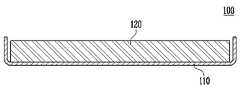
도 1은 유기 전계 발광표시장치의 개략적인 분해 사시도이다. 도 2는 도 1의 I-I' 부분을 절취한 단면도이다.1 is a schematic exploded perspective view of an organic light emitting display device. FIG. 2 is a cross-sectional view taken along the line II ′ of FIG. 1.
도 1 및 도 2를 참조하면, 유기 전계 발광표시장치(100)는 유기 전계 발광소자가 형성된 제1 기판, 상기 제1 기판 상부에 배치되는 제2 기판 및 상기 제1 기판과 제2 기판을 합착시키기 위한 밀봉재를 포함하는 표시 패널(120), 하부면(111) 및 상기 하부면(111)의 가장자리로부터 연장된 복수의 측벽(112,113,114)을 포함하며, 상기 하부면(111)과 상기 측벽(112,113,114)에 의해 상기 표시 패널(120)이 수용될 공간이 정의되는 베젤(110)을 포함한다.Referring to FIGS. 1 and 2, the organic light
표시 패널(120)은 유기 전계 발광소자가 형성된 제1 기판, 제1 기판 상부에 배치된 제2 기판 및 제1 기판과 제2 기판을 밀봉시키는 밀봉재를 포함한다.The
베젤(110)은 표시 패널(120)의 강도를 보강하기 위한 것으로, 베젤(110)은 하부면(111) 및 하부면(111)의 가장자리로부터 연장된 복수의 측벽(112,113,114)으로 이루어진다. 베젤(110)의 하부면(111)과 측벽(112,113,114)에 의해 표시 패널(120)의 수용 공간이 형성되고, 베젤(110)의 하부면(111)에 표시 패널(120)의 기판이 대응되고, 베젤(110)의 측벽(112,113,114)에 표시 패널(120)의 측벽이 대응되도록 표시 패널(120)이 수용된다.The
이때, 베젤(110)의 측벽(112,113,114)은 표시 패널(120)의 측면과 대응하여 배치되도록 베젤(110)의 하부면(111)을 직교하는 방향으로 연장될 수 있다.In this case, the
그러나 유기 전계 발광 표시 패널은 통상 유리 기판으로 형성됨에 따라 외부로부터 압력이 전달되었을 경우 표시 패널은 작은 충격에도 쉽게 변형되거나 파손될 수 있는 문제점을 갖는다.However, since the organic light emitting display panel is generally formed of a glass substrate, when the pressure is transmitted from the outside, the display panel may be easily deformed or broken even with a small impact.
따라서, 본 발명은 상기한 문제점을 해결하기 위하여 안출된 것으로서, 본 발명의 목적은 유기 전계 발광 표시 패널에 가해지는 응력을 감소시키기 위한 유기 전계 발광표시장치를 제공하는 것을 목적으로 한다.Accordingly, an object of the present invention is to provide an organic electroluminescent display device for reducing stress applied to an organic electroluminescent display panel.
전술한 목적을 달성하기 위한, 본 발명의 일 측면에 따르면, 본 발명의 유기 전계 발광표시장치는 유기 전계 발광 표시 패널; 하부면 및 측벽으로 이루어지며 상기 표시 패널을 수용하는 베젤 프레임; 상기 베젤 프레임이 수용되는 베젤; 및 상기 베젤 프레임 및 상기 베젤을 체결하는 체결 수단을 포함한다.According to an aspect of the present invention, an organic electroluminescent display device of the present invention comprises: an organic electroluminescent display panel; A bezel frame having a lower surface and a sidewall and accommodating the display panel; A bezel in which the bezel frame is accommodated; And fastening means for fastening the bezel frame and the bezel.
바람직하게, 상기 체결 수단은 상기 베젤 프레임의 측벽에 형성된 돌출부 및 상기 돌출부와 대응되는 상기 베젤의 내측면에 형성된 오목부를 포함하거나, 상기 체결 수단은 상기 베젤 프레임의 측벽에 형성된 돌출부 및 상기 돌출부와 대응되는 상기 베젤의 내측면에 형성된 관통 홀을 포함할 수 있다. 상기 돌출부는 복수 개로 형성될 수 있으며, 상기 돌출부는 상기 표시 패널이 상기 베젤에 수납되는 반대 방향의 측벽일 수 있다. 상기 베젤은 하부면, 측벽, 및 상기 측벽 중 적어도 하나의 측벽으로부터 연장되어 적어도 상기 표시 패널의 비화소영역과 대응되는 일 영역에 형성되는 상부면을 포함할 수 있으며, 상기 베젤의 상부면은 상기 표시 패널의 비화소영역과 대응될 수 있으며, 상기 베젤의 측벽은 상기 베젤의 하부면과 직교하는 방향으로 연장될 수 있으며, 상기 베젤의 상부면은 상기 베젤의 측벽과 직교하는 방향으로 연장될 수 있다. 상기 베젤은 하부면, 상기 하부면의 가장자리로부터 연장된 측벽을 포함할 수 있으며, 상기 베젤 프레임의 측벽은 상기 표시 패널의 세 측벽과 대응될 수 있다. 상기 베젤의 측벽은 상기 표시 패널의 네 측벽과 대응되며, 일 측벽의 높이가 상기 표시 패널의 높이 보다 낮을 수 있다. 상기 표시 패널과 상기 베젤 프레임 사이에 접착 부재를 더 포함할 수 있으며, 상기 표시 패널 상에 편광판이 더 포함할 수 있다. 상기 밀봉재는 무기 밀봉재일 수 있으며, 상기 베젤 및 상기 베젤 프레임은 스테인레스스틸(STS), 마그네슘, 마그네슘 합금으로 구성된 군에서 선택되는 하나일 수 있다.Preferably, the fastening means includes a protrusion formed on the sidewall of the bezel frame and a recess formed on the inner side of the bezel corresponding to the protrusion, or the fastening means corresponds to the protrusion formed on the sidewall of the bezel frame and the protrusion. It may include a through hole formed in the inner surface of the bezel. The protrusion may be formed in plural, and the protrusion may be a side wall of an opposite direction in which the display panel is accommodated in the bezel. The bezel may include a lower surface, a sidewall, and an upper surface extending from at least one sidewall of the sidewalls and formed on at least one region corresponding to the non-pixel area of the display panel, wherein the upper surface of the bezel The sidewalls of the bezel may extend in a direction orthogonal to the bottom surface of the bezel, and the top surface of the bezel may extend in a direction orthogonal to the sidewalls of the bezel. have. The bezel may include a bottom surface and sidewalls extending from an edge of the bottom surface, and the sidewalls of the bezel frame may correspond to three sidewalls of the display panel. Sidewalls of the bezel may correspond to four sidewalls of the display panel, and a height of one sidewall may be lower than that of the display panel. An adhesive member may be further included between the display panel and the bezel frame, and a polarizer may be further included on the display panel. The sealant may be an inorganic sealant, and the bezel and the bezel frame may be one selected from the group consisting of stainless steel (STS), magnesium, and magnesium alloy.
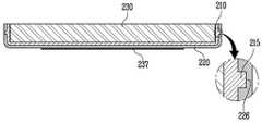
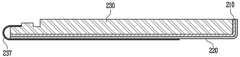
도 3은 본 발명의 제1 실시예에 따른 유기 전계 발광표시장치의 개략적인 분해 사시도이다. 도 4는 도 3의 Ⅱ-Ⅱ' 부분을 절취한 단면도이다. 도 5는 도 3의 Ⅲ-Ⅲ' 부분을 절취한 단면도이다.3 is a schematic exploded perspective view of an organic light emitting display device according to a first embodiment of the present invention. 4 is a cross-sectional view taken along the line II-II ′ of FIG. 3. 5 is a cross-sectional view taken along the line III-III ′ of FIG. 3.
도 3 내지 도 5를 참조하면, 유기 전계 발광표시장치(200)는 유기 전계 발광소자 표시 패널(230), 하부면(211) 및 측벽(212,213,214)으로 이루어지며 상기 표시 패널(230)이 수용되는 베젤 프레임(210) 및 상기 베젤 프레임(210)이 수용되는 베젤(220)을 포함하며, 상기 베젤(220)은 하부면(221), 상기 하부면(221)의 가장자리로부터 연장된 측벽(222,223,224)이 구비된다.3 to 5, the organic light emitting diode display 200 includes an organic light emitting
표시 패널(230)은 유기 전계 발광소자가 형성된 제1 기판(231), 제1 기판(231) 상부에 배치된 제2 기판(236) 및 제1 기판(231)과 제2 기판(236)을 밀봉시키는 밀봉재(235)를 포함한다.The
제1 기판(231)은 유기 전계 발광소자가 형성된 화소영역과 비화소영역을 포함한다. 화소영역에는 주사 라인 및 데이터 라인과, 주사 라인과 데이터 라인 사이에 매트릭스 방식으로 연결되어 화소를 구성하는 유기 전계 발광소자가 형성된다. 비화소영역은 화소영역을 제외한 제1 기판(231)의 전 영역으로, 비화소영역에는 화소영역의 주사 라인과 데이터 라인으로부터 연장된 주사 라인 및 데이터 라인, 유기 전계 발광소자의 동작을 위한 전원 전압 공급라인, 패드부(234)를 통해 외부로부터 제공된 신호를 처리하여 주사 라인 및 데이터 라인으로 공급하는 주사 구동부 및 데이터 구동부가 형성된다.The
유기 전계 발광소자는 애노드 전극, 발광층 및 캐소드 전극으로 구성되며, 애노드 전극과 캐소드 전극에 소정의 전압이 인가되면 애노드 전극을 통해 주입되는 정공과 캐소드 전극을 통해 주입되는 전자가 발광층에서 재결합하게 되어 빛을 외부로 방출한다. 패드부(234)는 필름 형태의 FPC(Flexible Printed Circuit:237)와 접속되고, FPC(237)는 베젤(220)의 하부면을 따라 외부로 노출된다. 이와 같이 외부로 노출된 FPC(237)를 통해 유기 전계 발광소자에 전원 전압, 주사 신호 및 데이터 신호가 입력될 수 있다.The organic electroluminescent device is composed of an anode electrode, a light emitting layer, and a cathode electrode. When a predetermined voltage is applied to the anode electrode and the cathode electrode, holes injected through the anode electrode and electrons injected through the cathode electrode are recombined in the light emitting layer. Emits to the outside. The
제2 기판(236)은 제1 기판(231) 상에 형성된 유기 전계 발광소자를 산소 및 수분으로부터 보호하기 위한 것으로, 제1 기판(231)과 제2 기판(236) 사이에 밀봉재(235)를 형성하여 제1 기판(231)과 제2 기판(236)을 접합 또는 외기로부터 밀봉시킨다. 이때, 밀봉재(235)는 유기 전계 발광소자의 둘레 방향을 따라 형성된다. 밀봉재(235)는 무기 또는 유기 밀봉재 등의 다양한 재료로 사용될 수 있다. 바람직하게는, 무기 밀봉재인 프릿으로 형성할 수 있다. 예를 들어, 프릿은 K2O, Fe2O3, Sb2O3, ZnO, P2O5, V2O5, TiO2, Al2O3, B2O3, WO3, SnO 및 PbO로 이루어진 군으로부터 선택된 적어도 하나로 형성될 수 있다.The
표시 패널(230) 상에는 외광 반사 차단을 위한 편광판(미도시)이 부착될 수 있다.A polarizer (not shown) may be attached to the
표시 패널(230)의 강도 보강하기 위해, 표시 패널(230)을 베젤 프레임(210) 내부에 수용한다. 표시 패널(230)은 인서트(insert) 방식에 의해 베젤 프레임(210) 내부에 수용될 수 있으며, 표시 패널(230)의 하부면과 접촉되는 베젤 프레임(210)의 하부면(211)에 접착 부재를 더 형성하여 표시 패널(230)을 베젤 프레임(210)에 고정시킬 수 있다. 이때, 접착 부재는 비닐 소재로 형성된 테이프 또는 접착제 중 하나로 형성될 수 있다.In order to reinforce the strength of the
베젤 프레임(210)을 보다 구체적으로 살펴보면, 베젤 프레임(210)은 하부면(211), 하부면(211)의 가장자리로부터 연장된 복수의 측벽(212,213,214)으로 이루어진다. 베젤 프레임(210)은 하부면(211)과 측벽(212,213,214)에 의해 표시 패널(230)의 수용 공간이 형성되고, 베젤 프레임(210)의 하부면(211)에 표시 패널(230)의 하부면이 대응되고, 베젤 프레임(210)의 측벽(212,213,214)에 표시 패널(230)의 측벽이 대응된다. 이러한 베젤 프레임(210)은 베젤(220)로부터 전달되는 응력이 표시 패널(230)로 재 전달되는 것을 방지하기 위한 것으로, 표시 패널(230)의 하부면(211) 및 측벽(212,213,214)을 감싸는 형상으로 형성된다. 또한, 베젤 프레임(210)은 표시 패널(230)의 강도를 보강하기 위한 것으로, 충격 흡수율이 높은 스테인레스스틸(STS), 마그네슘, 마그네슘 합금으로 구성된 군에서 선택되는 하나로 형성될 수 있다.Looking at the
한편, 표시 패널(230)은 외부로부터의 충격으로 인한 변형 및 파손을 방지하기 위해, 표시 패널(230)이 수용된 베젤 프레임(210)을 베젤(220) 내부에 수납한 다.On the other hand, the
표시 패널(230)을 포함하는 베젤 프레임(210)을 베젤(220)에 수용하기 위해서는, 체결 수단을 이용하여, 인서트 슬라이딩(insert sliding) 방식으로 베젤 프레임(210)을 베젤(220)에 수용시킬 수 있다. 인서트 슬라이딩 방식이란, 도 3에 도시된 화살표 방향(↓)과 같이 상부면이 형성되지 않은 베젤(220)의 상부 방향으로 베젤 프레임(210)을 베젤(220)로 슬라이딩시켜 수용시키는 것이다.In order to accommodate the
체결 수단은 베젤 프레임(210)의 측벽(212,214)에 형성된 돌출부(215)와 베젤(220)의 측벽(222,224) 내측부에 형성된 오목부(226)를 포함한다. 보다 구체적으로, 돌출부(215)는 표시 패널(230)이 수납되는 방향과 반대방향의 베젤 프레임(210)의 측벽(212,214)에 적어도 하나가 형성되고, 오목부(226)는 돌출부(215)와 대응되는 베젤(220)의 내측벽(222,224)에 형성된다. 돌출부(215)는 다양한 형태로 형성될 수 있으며, 본 발명의 제1 실시예에서는 설명의 편의상 돌출부(215)를 네모 형태로 형성한다. 또한, 오목부(226)는 돌출부(215)를 수용하는 홈으로, 돌출부(215)와 동일한 형태의 오목한 홈으로 형성될 수 있다.The fastening means includes a
이와 같은 돌출부(215)와 오목부(226)는 베젤(220) 내부에 수납된 베젤 프레임(210)의 탈리를 방지한다. 즉, 인서트 슬라이딩 방식에 의해 베젤 프레임(210)이 베젤(220)에 수납될 때, 베젤 프레임(210)의 돌출부(215)가 베젤(220)에 형성된 오목부(226)에 체결되어 베젤 프레임(210)이 베젤(220)로부터 탈리되는 것을 방지하는 것이다. 또한, 베젤 프레임(210)은 인서트 슬라이딩 방식에 의해 베젤(220) 내측면에 수용됨으로써, 베젤 프레임(210)의 측벽(212,213,214)과 베젤(220)의 측 벽(222,223,224) 사이의 이격 공간을 제거하여 표시 패널(230)의 흔들림을 방지할 수 있다.The
이러한 베젤(220)의 형상을 구체적으로 살펴보면, 베젤(220)은 하부면(221), 하부면(221)의 가장자리로부터 연장된 복수의 측벽(222,223,224)으로 이루어진다.Looking at the shape of the
예를 들어, 베젤(220)의 측벽(222,223,224)은 베젤 프레임(210)의 측벽(212,213,214)과 대응하여 배치되도록 베젤(220)의 하부면(221)과 직교하는 방향으로 연장되어 형성된다. 또한, 베젤(220)은 하부면(211)과 하부면의 가장자리로부터 연장된 네 개의 측벽으로 형성될 수 있다. 이때, 일 측벽의 높이(height)는 다른 측벽의 높이와 다르게 형성될 수 있다. 즉, 일 측벽의 높이는 표시 패널(230)의 제1 기판(231)의 높이와 동일하게, 혹은 그보다 낮게 형성되어 FPC(237)가 패드부(234)에 용이하게 제공될 수 있으며, 표시 패널(230)의 전 측면을 보호할 수 있다.For example, the
베젤(220) 내부에 수용된 베젤 프레임(210)과 베젤(220)의 수납 방향을 살펴보면, 베젤(220)의 하부면(221)과 베젤 프레임(210)의 하부면(211)이 대응되고, 베젤(220)의 측벽(222,223,224)과 베젤 프레임(210)의 측벽(212,213,214)이 대응되도록 수용된다.Looking at the
이러한, 베젤(220)은 베젤 프레임(210)과 동일한 물질로 형성될 수 있다. 베젤 프레임(210)과 베젤(220)은 스테인레스스틸(STS), 마그네슘, 마그네슘 합금으로 구성된 군에서 선택되는 하나를 절곡하거나, 사출 공정을 통해 제작할 수 있다. 또한, 베젤(220)의 측벽(222,223,224), 베젤 프레임(210)의 측벽(212,213,214)은 베젤(220)의 하부면(221) 또는 베젤 프레임(210)의 하부면(211)과 서로 연결되어 일체형으로 형성되거나 서로 분리된 구조로 제작된 후 조립될 수 있다.The
이와 같이 베젤(220)은 표시 패널(230)을 수용하는 베젤 프레임(210)의 하부면(211) 및 측벽(212,213,214)으로 형성되어, 외부의 압력 또는 충격으로부터 표시 패널(230)을 보호할 수 있다.As described above, the
도 6은 본 발명의 제2 실시예에 따른 유기 전계 발광표시장치의 개략적인 분해 사시도이다.6 is a schematic exploded perspective view of an organic light emitting display device according to a second embodiment of the present invention.
도 6을 참조하면, 유기 전계 발광표시장치(300)는 유기 전계 발광 표시 패널(330), 하부면(311) 및 측벽(312,313,314)으로 이루어지며 상기 표시 패널(330)이 수용되는 베젤 프레임(310) 및 상기 베젤 프레임(310)이 수용되는 베젤(320)을 포함하며, 상기 베젤(320)은 하부면(321), 상기 하부면(321)의 가장자리로부터 연장된 측벽(322,323,324)이 구비된다.Referring to FIG. 6, the organic light emitting
본 발명의 제2 실시예는 제1 실시예와 전체적으로 동일하되, 표시 패널(330)을 포함하는 베젤 프레임(310)을 도 6에 도시된 화살표 방향(→)과 같이 측벽이 형성되지 않은 베젤(320)의 측면 방향으로 베젤 프레임(310)을 베젤(320)로 슬라이딩시켜 수용한다.The second embodiment of the present invention is the same as that of the first embodiment, but the
또한, 체결 수단은 베젤 프레임(310)의 측벽(312,314)에 형성된 돌출부(315)와 베젤(320)의 측벽(322,324) 내측부에 형성된 오목부(326)를 포함한다.In addition, the fastening means includes a
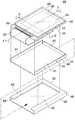
도 7은 본 발명의 제3 실시예에 따른 유기 전계 발광표시장치의 개략적인 분해 사시도이다. 도 8은 도 7의 Ⅳ-Ⅳ' 부분을 절취한 단면도이다. 도 9는 도 7의 Ⅴ-Ⅴ' 부분을 절취한 단면도이다.7 is a schematic exploded perspective view of an organic light emitting display device according to a third embodiment of the present invention. FIG. 8 is a cross-sectional view taken along the line IV-IV ′ of FIG. 7. FIG. 9 is a cross-sectional view taken along the line VV ′ of FIG. 7.
도 7 내지 도 9를 참조하면, 유기 전계 발광표시장치(400)는 적어도 하나의 유기 전계 발광소자가 형성된 화소영역(432) 및 비화소영역(433)을 포함하는 표시 패널(430), 하부면(411) 및 측벽(412,413,414)으로 이루어지며 상기 표시 패널(430)이 수용되는 베젤 프레임(410) 및 상기 베젤 프레임(410)이 수용되는 베젤(420)을 포함하며, 상기 베젤(420)은 하부면(421), 측벽(422,423,424) 및 상기 측벽(422,423,424) 중 적어도 하나의 측벽으로부터 연장되어 적어도 상기 표시 패널(430)의 비화소영역(433)과 대응되는 일 영역에 상부면(425)이 구비된다.7 through 9, the organic light emitting
표시 패널(430)은 유기 전계 발광소자가 형성된 제1 기판(431), 제1 기판(431) 상부에 배치된 제2 기판(436) 및 제1 기판(431)과 제2 기판(436)을 밀봉시키는 밀봉재(435)를 포함한다.The
제1 기판(431)은 유기 전계 발광소자가 형성된 화소영역(432)과 비화소영역(433)을 포함한다. 화소영역(432)에는 주사 라인 및 데이터 라인과, 주사 라인과 데이터 라인 사이에 매트릭스 방식으로 연결되어 화소를 구성하는 유기 전계 발광소자가 형성된다. 비화소영역(433)은 화소영역(432)을 제외한 제1 기판(431)의 전 영역으로, 비화소영역(433)에는 화소영역(432)의 주사 라인과 데이터 라인으로부터 연장된 주사 라인 및 데이터 라인, 유기 전계 발광소자의 동작을 위한 전원 전압 공급라인, 패드부(434)를 통해 외부로부터 제공된 신호를 처리하여 주사 라인 및 데이터 라인으로 공급하는 주사 구동부 및 데이터 구동부가 형성된다.The
패드부(434)는 필름 형태의 FPC(Flexible Printed Circuit:437)와 접속되고, FPC(437)는 베젤(420)의 하부면을 따라 외부로 노출된다. 이와 같이 외부로 노출된 FPC(437)를 통해 유기 전계 발광소자에 전원 전압, 주사 신호 및 데이터 신호가 입력될 수 있다.The
제2 기판(436)은 제1 기판(431) 상에 형성된 유기 전계 발광소자를 산소 및 수분으로부터 보호하기 위한 것으로, 제1 기판(431)과 제2 기판(436) 사이에 밀봉재(435)를 형성하여 제1 기판(431)과 제2 기판(436)을 접합 또는 외기로부터 밀봉시킨다. 이때, 밀봉재(435)는 유기 전계 발광소자의 둘레 방향을 따라 형성된다. 밀봉재(435)는 무기 또는 유기 밀봉재 등의 다양한 재료로 사용가 사용될 수 있다. 바람직하게는, 무기 밀봉재인 프릿으로 형성할 수 있다.The
표시 패널(430) 상에는 외광 반사 차단을 위한 편광판(미도시)이 부착될 수 있다.A polarizer (not shown) may be attached to the
표시 패널(430)의 강도를 보강하기 위해, 표시 패널(430)을 베젤 프레임(410) 수용한다. 표시 패널(430)은 인서트 (insert) 방식에 의해 베젤 프레임(410) 내부에 수용될 수 있으며, 표시 패널(430)의 하부면과 접촉되는 베젤 프레임(410)의 하부면(411)에 접착 부재를 더 형성하여 표시 패널(430)을 베젤 프레임(410)에 고정시킬 수 있다. 이때, 접착 부재는 비닐 소재로 형성된 테이프 또는 접착제 중 하나로 형성될 수 있다.In order to reinforce the strength of the
베젤 프레임(410)을 보다 구체적으로 살펴보면, 베젤 프레임(410)은 하부면(411), 하부면(411)의 가장자리로부터 연장된 복수의 측벽(412,413,414)으로 이루어진다. 베젤 프레임(410)은 하부면(411)과 측벽(412,413,414)에 의해 표시 패널(430)의 수용 공간이 형성되고, 베젤 프레임(410)의 하부면(411)에 표시 패널(430)의 하부면이 대응되고, 베젤 프레임(410)의 측벽(412,413,414)에 표시 패널(430)의 측벽이 대응된다. 이러한 베젤 프레임(410)은 베젤(420)로부터 전달되는 응력이 표시 패널(430)로 재 전달되는 것을 방지하기 위한 것으로, 표시 패널(430)의 하부면(411) 및 측벽(412,413,414)을 감싸는 형상으로 형성된다. 또한, 베젤 프레임(410)은 표시 패널(430)의 강도를 보강하기 위한 것으로, 충격 흡수율이 높은 스테인레스스틸(STS), 마그네슘, 마그네슘 합금으로 구성된 군에서 선택되는 하나로 형성될 수 있다.Looking at the
한편, 표시 패널(430)은 외부로부터의 충격으로 인한 변형 및 파손을 방지하기 위해, 표시 패널(430)이 수용된 베젤 프레임(410)을 베젤(420) 내부에 수납한다.Meanwhile, the
표시 패널(430)을 포함하는 베젤 프레임(410)을 베젤(420)에 수용하기 위해서는, 체결 수단을 이용하여, 인서트 슬라이딩(insert sliding) 방식으로 베젤 프레임(410)을 베젤(420) 내부에 수용시킬 수 있다. 인서트 슬라이딩 방식이란, 도 7에 도시된 화살표 방향(→)과 같이 측벽이 형성되지 않은 베젤(410)의 개구부 방향으로 베젤 프레임(410)을 베젤(420)로 슬라이딩시켜 수용하는 것이다.In order to accommodate the
체결 수단은 베젤 프레임(410)의 측벽(412,414)에 형성된 돌출부(415)와 베젤(420) 측벽(422,424) 내측부에 형성된 오목부(426)를 포함한다. 보다 구체적으로, 돌출부(415)는 표시 패널(430)이 수납되는 방향과 반대방향의 베젤 프레임(410)의 측벽(412,414)에 복수 개가 형성되고, 오목부(426)는 돌출부(415)와 대응되는 베젤(420)의 내측벽(422,424)에 형성된다. 돌출부(415)는 다양한 형태로 형성될 수 있으며, 본 발명의 제3 실시예에서는 설명의 편의상 돌출부(415)를 동그란 형태로 형성한다. 또한, 오목부(426)는 돌출부(415)를 수용하는 홈으로, 돌출부(415)와 동일한 형태의 오목한 홈으로 형성될 수 있다.The fastening means includes
이와 같은 돌출부(415)와 오목부(426)는 베젤(420) 내부에 수납된 베젤 프레임(410)의 탈리를 방지한다. 즉, 인서트 슬라이딩 방식에 의해 베젤 프레임(410)이 베젤(420)에 수납될 때, 베젤 프레임(410)의 돌출부(415)가 베젤(420)에 형성된 오목부(426)에 체결되어 베젤 프레임(410)이 베젤(420)로부터 탈리되는 것을 방지하는 것이다. 또한, 베젤 프레임(410)은 인서트 슬라이딩 방식에 의해 베젤(420) 내측면에 수용됨으로써, 베젤 프레임(410)의 측벽(412,413,414)과 베젤(420)의 측벽(422,423,424) 사이의 이격 공간을 제거하여 표시 패널(430)의 흔들림을 방지할 수 있다.The
이러한 베젤(420)의 형상을 구체적으로 살펴보면, 베젤(420)은 하부면(421), 하부면(421)의 가장자리로부터 연장된 복수의 측벽(422,423,424), 및 복수의 측벽(422,423,424) 중 적어도 하나의 측벽의 가장자리로부터 연장되며, 표시 패널(430)의 적어도 비화소영역(433)의 일 부분과 대응되는 상부면(425)으로 이루어 진다. 이때, 베젤(420)의 상부면(425)은 표시 패널(430)의 화소영역(422)으로부터 방출되는 빛의 간섭을 방지하기 위해, 비화소영역(433)과 대응되는 일 영역에만 상부면(425)을 형성한다.Looking at the shape of the
예를 들어, 베젤(420)의 측벽(422,423,424)은 베젤 프레임(410)의 측벽(412,413,414)과 대응하여 배치되도록 베젤(420)의 하부면(421)과 직교하는 방향으로 연장되어 형성되며, 베젤(420)의 상부면(425)은 표시 패널(430)의 비화소영역(433)과 대응되는 영역에 베젤(420) 측벽(422,423,424)의 가장자리로부터 표시 패널(430)이 수납되는 수납방향으로 연장되어 형성된다.For example, the
베젤(420) 내부에 수용된 베젤 프레임(410)과 베젤(420)의 수납 방향을 살펴보면, 베젤(420)의 하부면(421)과 베젤 프레임(410)의 하부면(411)이 대응되고, 베젤(420)의 측벽(422,423,424)과 베젤 프레임(410)의 측벽(412,413,414)이 대응되고, 베젤(420)의 상부면(425)과 표시 패널(430)의 비화소영역(433)과 대응되도록 수용된다.Looking at the
이러한, 베젤(420)은 베젤 프레임(410)과 동일한 물질로 형성될 수 있다. 베젤 프레임(410)과 베젤(420)은 스테인레스스틸(STS), 마그네슘, 마그네슘 합금으로 구성된 군에서 선택되는 하나를 절곡하거나, 사출 공정을 통해 제작할 수 있다. 또한, 베젤(420)의 측벽(422,423,424), 베젤(420)의 상부면(425), 베젤 프레임(410)의 측벽(412,413,414)은 베젤(420)의 하부면(421) 또는 베젤 프레임(410)의 하부면(411)과 서로 연결되어 일체형으로 형성되거나 서로 분리된 구조로 제작된 후 조립될 수 있다.The
이와 같이 베젤(420)은 표시 패널(430)을 수용하는 베젤 프레임(410)의 하부면(411), 측벽(412,413,414) 및 상부면을 둘러싸는 페루프 형태로 형성됨에 따라, 외부의 압력 또는 충격으로부터 표시 패널(430)의 하부면, 측벽 및 상부면(상부 모서리(edge) 영역을 보호할 수 있다. 또한, 베젤(420)은 표시 패널(430)의 비화소 영역(433)의 적어도 일 영역과 대응되는 상부면(425)을 구비함에 따라, 정전기(ESD) 등에 취약한 표시 패널(430)의 상부 모서리 영역을 정전기로부터 보호할 수 있다.As described above, the
도 10은 본 발명에 따른 베젤의 일 실시예를 나타내는 분해 사시도이다.10 is an exploded perspective view showing an embodiment of the bezel according to the present invention.
도 10을 참조하면, 베젤(520)은 하부면(521), 하부면(521)으로부터 연장되어 하부면(521)과 직교하는 방향으로 형성된 복수의 측벽(522,523,524) 및 복수의 측벽(522,523,524) 중 적어도 하나의 측벽으로부터 연장된 상부면(522a,524a)을 포함한다. 이때, 상부면(522a,524a)은 복수의 측벽(522,523,524) 중 제1 측벽(522) 및 제3 측벽(524)의 가장자리로부터 연장되어 제1 측벽(522) 및 제3 측벽(524)과 직교하는 방향 즉, 하부면(521)과 평행하는 방향으로 연장되어 형성될 수 있다. 또한, 베젤(520)의 상부면(522a,524a)은 베젤(520) 내부에 수용되는 표시 패널의 비화소영역과 대응되는 적어도 일 영역에 제1 상부면(522a) 및 제2 상부면(524a)을 형성하여 표시 패널의 상부 및 상부 모서리 영역을 보호할 수 있다.Referring to FIG. 10, the
이러한, 베젤(520)은 하부면(521), 측벽(522,523,524) 및 상부면(522a,524a)은 원형의 단면을 갖는 바(bar) 형상 또는 사각 단면을 갖는 바(bar) 형상으로 형 성될 수 있다.The
도 11은 본 발명에 따른 베젤의 다른 일 실시예를 나타내는 분해 사시도이다.11 is an exploded perspective view showing another embodiment of the bezel according to the present invention.
도 11을 참조하면, 베젤(620)은 하부면(621), 하부면(621)의 가장자리로부터 연장되어 하부면(621)과 직교하는 방향으로 형성된 복수의 측벽(622,623,624) 및 복수의 측벽(622,623,624)의 가장자리로부터 연장되어 표시 패널의 비화소영역과 대응되는 상부면(625)을 포함한다. 이때, 상부면(625)은 복수의 측벽(622,623,624) 중 제1,2,3 측벽(622,623,624)으로부터 연장되어 제1,2,3 측벽(622,623,624)과 직교하는 방향 즉, 표시 패널의 비화소영역과 대응되는 전 영역에 형성된다. 또한, 베젤(620)의 상부면(625)은 베젤(620) 내부에 수용되는 표시 패널의 화소영역과 대응되는 영역에 개구부를 형성하여 화소영역으로부터 발광되는 빛의 간섭을 방지할 수 있다.Referring to FIG. 11, the
도 12는 본 발명에 따른 베젤의 또 다른 일 실시예를 나타내는 분해 사시도이다.12 is an exploded perspective view showing yet another embodiment of the bezel according to the present invention.
도 12를 참조하면, 베젤(720)은 하부면(721), 하부면(721)으로부터 연장되어 하부면(721)과 직교하는 방향으로 형성된 복수의 측벽(722,723,724) 및 복수의 측벽(722,723,724) 중 적어도 하나의 측벽으로부터 연장된 상부면(722a,724a)을 포함한다. 상부면(722a,724a)은 복수의 측벽(722,723,724) 중 제1 측벽(722) 및 제3 측벽(724)의 가장자리로부터 연장되어 제1 측벽(722) 및 제3 측벽(724)과 직교하는 방향으로 표시 패널의 상부 모서리 영역을 둘러싸는 형상으로 형성될 수 있다.Referring to FIG. 12, the
도 13은 본 발명에 따른 베젤 프레임 및 베젤의 체결형상을 나타내는 단면도이다.13 is a cross-sectional view showing the fastening shape of the bezel frame and the bezel according to the present invention.
도 13을 참조하면, 유기 전계 발광표시장치(800)는 적어도 하나의 유기 전계 발광소자가 형성된 화소영역 및 비화소영역을 포함하는 표시 패널(830), 하부면 및 측벽으로 이루어지며 상기 표시 패널(830)이 수용되는 베젤 프레임(810) 및 상기 베젤 프레임(810)이 수용되는 베젤(820)을 포함하며, 상기 베젤(820)은 하부면, 측벽 및 상기 측벽 중 적어도 하나의 측벽으로부터 연장되어 적어도 상기 표시 패널(830)의 비화소영역과 대응되는 일 영역에 상부면이 구비된다.Referring to FIG. 13, the organic light emitting
체결 수단은 본 발명의 제3 실시예와 전체적으로 동일하되, 돌출부(815)와 대응되는 베젤(820)에 관통 홀(826)로 형성된다. 보다 구체적으로, 돌출부(815)는 표시 패널(830)이 수납되는 방향과 반대방향의 베젤 프레임(810)의 측벽에 복수 개가 형성되고, 관통 홀(826)은 돌출부(815)와 대응되는 베젤(820)에 상응하는 수 만큼 형성될 수 있다.The fastening means is generally the same as the third embodiment of the present invention, but is formed as a through
관통 홀(826)은 돌출부(815)를 수용하는 홈으로, 돌출부(815)와 동일한 형태 또는 사각 형상의 홀(hole)로 형성되어, 베젤 프레임(810)과 베젤(820)을 체결시킬 수 있다. 즉, 베젤 프레임(810)의 돌출부(815)가 베젤(820) 측벽에 형성된 관통 홀(826) 내부에 삽입되어 베젤 프레임(810)과 베젤(820)이 체결되는 것이다.The through
이상 본 발명을 상세히 설명하였으나 본 발명은 이에 한정되지 않으며, 본 발명이 속하는 기술적 사상 내에서 당 분야의 통상의 지식을 가진 자에 의해 많은 변형할 수 있은 물론이다.Although the present invention has been described in detail above, the present invention is not limited thereto, and many modifications can be made by those skilled in the art within the technical idea to which the present invention pertains.
이상과 같이, 본 발명에 따른 유기전계 발광표시장치는 유기 전계 발광 표시 패널을 보호하는 베젤 프레임을 더 구비하며, 유기 전계 발광 표시 패널에 가해지는 응력을 약화시키수 있다. 또한, 베젤 프레임은 인서트 슬라이딩 방식에 의해 베젤 내부에 삽입됨으로써 접착 부재를 이용하지 않고 베젤 프레임을 베젤 내부에 수용할 수 있다.As described above, the organic light emitting display device according to the present invention further includes a bezel frame that protects the organic light emitting display panel, thereby reducing the stress applied to the organic light emitting display panel. In addition, the bezel frame is inserted into the bezel by the insert sliding method so that the bezel frame can be accommodated inside the bezel without using an adhesive member.
베젤은 적어도 표시 패널의 비화소영역의 일 영역과 대응되는 상부면을 구비하여 표시 패널의 상부 및 상부 모서리를 보호할 수 있다. 또한, 베젤은 상부면을 구비함에 따라, 정전기(ESD) 등에 취약한 표시 패널의 상부 모서리 영역을 정전기로부터 보호할 수 있다.The bezel may have an upper surface corresponding to at least one region of the non-pixel area of the display panel to protect upper and upper edges of the display panel. In addition, since the bezel has an upper surface, the upper edge area of the display panel, which is vulnerable to static electricity (ESD), may be protected from static electricity.
Claims (16)
Translated fromKoreanPriority Applications (2)
| Application Number | Priority Date | Filing Date | Title |
|---|---|---|---|
| KR1020070050322AKR100857689B1 (en) | 2007-05-23 | 2007-05-23 | Organic electroluminescent display |
| US12/124,022US8350979B2 (en) | 2007-05-23 | 2008-05-20 | Organic light emitting display device |
Applications Claiming Priority (1)
| Application Number | Priority Date | Filing Date | Title |
|---|---|---|---|
| KR1020070050322AKR100857689B1 (en) | 2007-05-23 | 2007-05-23 | Organic electroluminescent display |
Publications (1)
| Publication Number | Publication Date |
|---|---|
| KR100857689B1true KR100857689B1 (en) | 2008-09-08 |
Family
ID=40022840
Family Applications (1)
| Application Number | Title | Priority Date | Filing Date |
|---|---|---|---|
| KR1020070050322AActiveKR100857689B1 (en) | 2007-05-23 | 2007-05-23 | Organic electroluminescent display |
Country Status (2)
| Country | Link |
|---|---|
| US (1) | US8350979B2 (en) |
| KR (1) | KR100857689B1 (en) |
Cited By (2)
| Publication number | Priority date | Publication date | Assignee | Title |
|---|---|---|---|---|
| KR101306135B1 (en) | 2009-09-17 | 2013-09-09 | 엘지디스플레이 주식회사 | Organic electro-luminescence device |
| KR20160029192A (en)* | 2014-09-04 | 2016-03-15 | 삼성디스플레이 주식회사 | Display device |
Families Citing this family (8)
| Publication number | Priority date | Publication date | Assignee | Title |
|---|---|---|---|---|
| KR100857690B1 (en)* | 2007-05-30 | 2008-09-08 | 삼성에스디아이 주식회사 | Organic electroluminescent display |
| JP5559586B2 (en)* | 2010-04-07 | 2014-07-23 | パナソニック株式会社 | Organic EL module |
| KR101327743B1 (en)* | 2010-04-27 | 2013-11-11 | 엘지디스플레이 주식회사 | Display apparatus |
| TWI389067B (en)* | 2010-06-29 | 2013-03-11 | Compal Electronics Inc | Display module and assembly method thereof |
| CN104100877B (en)* | 2013-04-03 | 2016-11-09 | 宏达国际电子股份有限公司 | Light source module |
| KR20150046925A (en)* | 2013-10-23 | 2015-05-04 | 삼성디스플레이 주식회사 | A ligquid crystal display device |
| KR20150093278A (en) | 2014-02-06 | 2015-08-18 | 삼성디스플레이 주식회사 | Display apparatus |
| CN113891585B (en)* | 2021-12-09 | 2022-03-01 | 四川英创力电子科技股份有限公司 | A method of manufacturing a rigid-flex board |
Citations (1)
| Publication number | Priority date | Publication date | Assignee | Title |
|---|---|---|---|---|
| KR100645694B1 (en)* | 2005-12-21 | 2006-11-15 | 삼성에스디아이 주식회사 | Organic light emitting display |
Family Cites Families (25)
| Publication number | Priority date | Publication date | Assignee | Title |
|---|---|---|---|---|
| US5161028A (en)* | 1989-07-20 | 1992-11-03 | Kabushiki Kaisha Toshiba | Car-mounted video displaying apparatus |
| KR100556031B1 (en) | 1998-01-14 | 2006-05-23 | 삼성전자주식회사 | Structure of an LCD Module |
| KR100293825B1 (en) | 1998-12-23 | 2001-07-12 | 박종섭 | Liquid crystal display module |
| KR200348836Y1 (en) | 1999-06-29 | 2004-04-29 | 비오이 하이디스 테크놀로지 주식회사 | LCD device |
| KR100662882B1 (en) | 1999-10-05 | 2006-12-28 | 삼성전자주식회사 | Backlight assembly |
| KR100619582B1 (en) | 1999-10-08 | 2006-09-01 | 삼성전자주식회사 | Liquid crystal display module, liquid crystal display device employing the same, and assembly method thereof |
| KR100322104B1 (en) | 2000-02-02 | 2002-02-06 | 김순택 | Liquid Crystal Device Module |
| JP2001290434A (en) | 2000-04-04 | 2001-10-19 | Nec Corp | Display device |
| KR20010094205A (en) | 2000-04-04 | 2001-10-31 | 구자홍 | Structure for fixing a cover in a Liquid Crystal Display |
| KR100692677B1 (en) | 2000-06-30 | 2007-03-14 | 비오이 하이디스 테크놀로지 주식회사 | LCD bezel |
| KR100720411B1 (en)* | 2000-10-25 | 2007-05-22 | 엘지.필립스 엘시디 주식회사 | Liquid crystal display panel and manufacturing method thereof |
| TW540553U (en) | 2000-12-04 | 2003-07-01 | Chi Mei Optoelectronics Corp | Structure reinforced exterior frame for planar display device |
| JP2002182209A (en) | 2000-12-19 | 2002-06-26 | Advanced Display Inc | Liquid crystal display device |
| TW501834U (en)* | 2001-02-15 | 2002-09-01 | Quanta Comp Inc | Removable display-stand for cellular phone |
| TW589923B (en)* | 2003-04-10 | 2004-06-01 | Toppoly Optoelectronics Corp | Organic light emitted display having anti-reflective and inert cathode |
| JP4543655B2 (en) | 2003-10-17 | 2010-09-15 | ソニー株式会社 | Liquid crystal display |
| KR20050116271A (en) | 2004-06-07 | 2005-12-12 | 삼성전자주식회사 | Back light assembly and display device having the same |
| KR100603196B1 (en)* | 2004-06-21 | 2006-07-24 | 삼성전자주식회사 | LCD Module |
| KR100658082B1 (en) | 2004-11-30 | 2006-12-15 | 비오이 하이디스 테크놀로지 주식회사 | LCD Display Module |
| JP4581726B2 (en)* | 2004-12-28 | 2010-11-17 | ソニー株式会社 | Display device and portable device |
| JP4543385B2 (en) | 2005-03-15 | 2010-09-15 | 日本電気株式会社 | Manufacturing method of liquid crystal display device |
| JP4481218B2 (en)* | 2005-06-29 | 2010-06-16 | 株式会社 日立ディスプレイズ | Liquid crystal display |
| TWI321668B (en) | 2005-09-16 | 2010-03-11 | Au Optronics Corp | Flat panel display module |
| KR100729084B1 (en) | 2006-09-21 | 2007-06-14 | 삼성에스디아이 주식회사 | Organic electroluminescent display |
| KR100857690B1 (en) | 2007-05-30 | 2008-09-08 | 삼성에스디아이 주식회사 | Organic electroluminescent display |
- 2007
- 2007-05-23KRKR1020070050322Apatent/KR100857689B1/enactiveActive
- 2008
- 2008-05-20USUS12/124,022patent/US8350979B2/enactiveActive
Patent Citations (1)
| Publication number | Priority date | Publication date | Assignee | Title |
|---|---|---|---|---|
| KR100645694B1 (en)* | 2005-12-21 | 2006-11-15 | 삼성에스디아이 주식회사 | Organic light emitting display |
Cited By (4)
| Publication number | Priority date | Publication date | Assignee | Title |
|---|---|---|---|---|
| KR101306135B1 (en) | 2009-09-17 | 2013-09-09 | 엘지디스플레이 주식회사 | Organic electro-luminescence device |
| US9082998B2 (en) | 2009-09-17 | 2015-07-14 | Lg Display Co., Ltd. | Organic electroluminescent display module |
| KR20160029192A (en)* | 2014-09-04 | 2016-03-15 | 삼성디스플레이 주식회사 | Display device |
| KR102357508B1 (en)* | 2014-09-04 | 2022-02-04 | 삼성디스플레이 주식회사 | Display device |
Also Published As
| Publication number | Publication date |
|---|---|
| US20080291612A1 (en) | 2008-11-27 |
| US8350979B2 (en) | 2013-01-08 |
Similar Documents
| Publication | Publication Date | Title |
|---|---|---|
| KR100857689B1 (en) | Organic electroluminescent display | |
| KR100722119B1 (en) | Organic light emitting display device | |
| KR100769425B1 (en) | Organic light emitting display | |
| KR100729084B1 (en) | Organic electroluminescent display | |
| US8436958B2 (en) | Electronic device having organic light emitting diode display device | |
| KR101759577B1 (en) | On-cell TSP active matrix organic light emitting diode structure | |
| CN107464824B (en) | Display panel | |
| CN101093852B (en) | Organic EL display device | |
| KR100857690B1 (en) | Organic electroluminescent display | |
| KR102053411B1 (en) | Organic light emitting diode display | |
| KR20140144752A (en) | Organic light emitting display devices and methods of manufacturing organic light emitting display devices | |
| KR101949926B1 (en) | Organic Light Emitting diode and method of manufacturing the same | |
| KR102530802B1 (en) | Display Device | |
| US8659223B2 (en) | Light emitting diode display | |
| CN115050793B (en) | Display panel | |
| KR100922360B1 (en) | Organic light emitting display | |
| KR100629180B1 (en) | Organic electroluminescent display | |
| KR20120079677A (en) | Organic light emitting diode display | |
| KR100811981B1 (en) | Organic electroluminescent display | |
| KR101819749B1 (en) | Organic Light Emitting Diode Display Device | |
| US8330894B2 (en) | Display device | |
| JP2003151762A (en) | Display device | |
| KR101474222B1 (en) | Organic light emitting display | |
| KR100542987B1 (en) | Organic light emitting display device | |
| KR100637447B1 (en) | Organic light emitting display |
Legal Events
| Date | Code | Title | Description |
|---|---|---|---|
| A201 | Request for examination | ||
| PA0109 | Patent application | Patent event code:PA01091R01D Comment text:Patent Application Patent event date:20070523 | |
| PA0201 | Request for examination | ||
| E902 | Notification of reason for refusal | ||
| PE0902 | Notice of grounds for rejection | Comment text:Notification of reason for refusal Patent event date:20080331 Patent event code:PE09021S01D | |
| E701 | Decision to grant or registration of patent right | ||
| PE0701 | Decision of registration | Patent event code:PE07011S01D Comment text:Decision to Grant Registration Patent event date:20080818 | |
| GRNT | Written decision to grant | ||
| PR0701 | Registration of establishment | Comment text:Registration of Establishment Patent event date:20080902 Patent event code:PR07011E01D | |
| PR1002 | Payment of registration fee | Payment date:20080902 End annual number:3 Start annual number:1 | |
| PG1601 | Publication of registration | ||
| PR1001 | Payment of annual fee | Payment date:20110829 Start annual number:4 End annual number:4 | |
| FPAY | Annual fee payment | Payment date:20120831 Year of fee payment:5 | |
| PR1001 | Payment of annual fee | Payment date:20120831 Start annual number:5 End annual number:5 | |
| FPAY | Annual fee payment | Payment date:20130830 Year of fee payment:6 | |
| PR1001 | Payment of annual fee | Payment date:20130830 Start annual number:6 End annual number:6 | |
| FPAY | Annual fee payment | Payment date:20140901 Year of fee payment:7 | |
| PR1001 | Payment of annual fee | Payment date:20140901 Start annual number:7 End annual number:7 | |
| FPAY | Annual fee payment | Payment date:20160831 Year of fee payment:9 | |
| PR1001 | Payment of annual fee | Payment date:20160831 Start annual number:9 End annual number:9 | |
| FPAY | Annual fee payment | Payment date:20180829 Year of fee payment:11 | |
| PR1001 | Payment of annual fee | Payment date:20180829 Start annual number:11 End annual number:11 | |
| PR1001 | Payment of annual fee | Payment date:20200901 Start annual number:13 End annual number:13 | |
| PR1001 | Payment of annual fee | Payment date:20210825 Start annual number:14 End annual number:14 | |
| PR1001 | Payment of annual fee | Payment date:20220824 Start annual number:15 End annual number:15 | |
| PR1001 | Payment of annual fee | Payment date:20240822 Start annual number:17 End annual number:17 |