KR100856426B1 - Exercise device trajectory measuring device using a plurality of acceleration sensors and method - Google Patents
Exercise device trajectory measuring device using a plurality of acceleration sensors and methodDownload PDFInfo
- Publication number
- KR100856426B1 KR100856426B1KR1020070061606AKR20070061606AKR100856426B1KR 100856426 B1KR100856426 B1KR 100856426B1KR 1020070061606 AKR1020070061606 AKR 1020070061606AKR 20070061606 AKR20070061606 AKR 20070061606AKR 100856426 B1KR100856426 B1KR 100856426B1
- Authority
- KR
- South Korea
- Prior art keywords
- acceleration
- information
- exercise
- exercise device
- calculating
- Prior art date
- Legal status (The legal status is an assumption and is not a legal conclusion. Google has not performed a legal analysis and makes no representation as to the accuracy of the status listed.)
- Expired - Fee Related
Links
Images


Classifications
- A—HUMAN NECESSITIES
- A63—SPORTS; GAMES; AMUSEMENTS
- A63B—APPARATUS FOR PHYSICAL TRAINING, GYMNASTICS, SWIMMING, CLIMBING, OR FENCING; BALL GAMES; TRAINING EQUIPMENT
- A63B69/00—Training appliances or apparatus for special sports
- A63B69/36—Training appliances or apparatus for special sports for golf
- A—HUMAN NECESSITIES
- A63—SPORTS; GAMES; AMUSEMENTS
- A63B—APPARATUS FOR PHYSICAL TRAINING, GYMNASTICS, SWIMMING, CLIMBING, OR FENCING; BALL GAMES; TRAINING EQUIPMENT
- A63B24/00—Electric or electronic controls for exercising apparatus of preceding groups; Controlling or monitoring of exercises, sportive games, training or athletic performances
- A63B24/0003—Analysing the course of a movement or motion sequences during an exercise or trainings sequence, e.g. swing for golf or tennis
- A63B24/0006—Computerised comparison for qualitative assessment of motion sequences or the course of a movement
- A—HUMAN NECESSITIES
- A63—SPORTS; GAMES; AMUSEMENTS
- A63B—APPARATUS FOR PHYSICAL TRAINING, GYMNASTICS, SWIMMING, CLIMBING, OR FENCING; BALL GAMES; TRAINING EQUIPMENT
- A63B2220/00—Measuring of physical parameters relating to sporting activity
- A63B2220/40—Acceleration
- A—HUMAN NECESSITIES
- A63—SPORTS; GAMES; AMUSEMENTS
- A63B—APPARATUS FOR PHYSICAL TRAINING, GYMNASTICS, SWIMMING, CLIMBING, OR FENCING; BALL GAMES; TRAINING EQUIPMENT
- A63B2220/00—Measuring of physical parameters relating to sporting activity
- A63B2220/40—Acceleration
- A63B2220/44—Angular acceleration
- A—HUMAN NECESSITIES
- A63—SPORTS; GAMES; AMUSEMENTS
- A63B—APPARATUS FOR PHYSICAL TRAINING, GYMNASTICS, SWIMMING, CLIMBING, OR FENCING; BALL GAMES; TRAINING EQUIPMENT
- A63B2220/00—Measuring of physical parameters relating to sporting activity
- A63B2220/80—Special sensors, transducers or devices therefor
- A63B2220/803—Motion sensors
- A—HUMAN NECESSITIES
- A63—SPORTS; GAMES; AMUSEMENTS
- A63B—APPARATUS FOR PHYSICAL TRAINING, GYMNASTICS, SWIMMING, CLIMBING, OR FENCING; BALL GAMES; TRAINING EQUIPMENT
- A63B2225/00—Miscellaneous features of sport apparatus, devices or equipment
- A63B2225/50—Wireless data transmission, e.g. by radio transmitters or telemetry
Landscapes
- Health & Medical Sciences (AREA)
- General Health & Medical Sciences (AREA)
- Physical Education & Sports Medicine (AREA)
- Measurement Of The Respiration, Hearing Ability, Form, And Blood Characteristics Of Living Organisms (AREA)
- Force Measurement Appropriate To Specific Purposes (AREA)
Abstract
Translated fromKoreanDescription
Translated fromKorean도 1은 이 발명의 한 실시예에 따른 복수의 가속도 센서를 이용한 운동기구 궤적 측정장치의 구성관계를 도시한 기능 블록도이고,1 is a functional block diagram showing the configuration of the exercise device trajectory measuring device using a plurality of acceleration sensors according to an embodiment of the present invention,
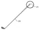
도 2는 이 발명에 따른 전자감지수단이 장착된 골프 클럽을 도시한 개념도이고,2 is a conceptual diagram showing a golf club equipped with an electronic sensing means according to the present invention,
도 3은 도 2에 도시된 골프 클럽의 그립측 단부의 확대도이며,3 is an enlarged view of the grip side end portion of the golf club shown in FIG.
도 4는 도 3에 도시된 전자감지수단의 센서 기능을 설명하기 위한 확대도이다.FIG. 4 is an enlarged view for explaining a sensor function of the electronic sensing unit shown in FIG. 3.
♠ 도면의 주요부분에 대한 부호의 설명 ♠ ♠ Explanation of symbols on the main parts of the drawing ♠
110 : 전자감지수단 111 : 제1 가속도센서110: electronic detection means 111: the first acceleration sensor
112 : 제2 가속도센서 113 : 제3 가속도센서112: second acceleration sensor 113: third acceleration sensor
114 : 제4 가속도센서 115 : 제어부114: fourth acceleration sensor 115: control unit
116 : 저장부 117 : 무선 송신부116: storage unit 117: wireless transmission unit
120 : 중앙계산수단 121 : 무선 수신부120: central calculation means 121: wireless receiver
122 : 계산부 123 : 표시부122: calculation unit 123: display unit
[문헌 정보 1] 국내 특허출원 제2005-0084589호(골프스윙안내장치)[Document Information 1] Domestic Patent Application No. 2005-0084589 (Golf Swing Guide Device)
[문헌 정보 2] 국내 특허출원 제2006-70218213호(골프 스윙의 동작 특성을 결정하는 시스템)[Document Information 2] Domestic Patent Application No. 2006-70218213 (system for determining the operating characteristics of the golf swing)
[문헌 정보 3] 국내 특허출원 제2005-0093310호(골프 스윙 진단장치)[Document Information 3] Domestic Patent Application No. 2005-0093310 (Golf Swing Diagnosis Device)
[문헌 정보 4] 국내 특허출원 제2005-0238215호(골프용 정보 단말기)[Document Information 4] Domestic Patent Application No. 2005-0238215 (Golf Information Terminal)
[문헌 정보 5] 국내 특허출원 제2003-0008126호(골프채를 이용한 원심력 측정 방법 및 그러한 방법에 의해 원심력을 측정할 수 있는 골프채)[Reference Information 5] Domestic Patent Application No. 2003-0008126 (Method of Measuring Centrifugal Force Using Golf Club and Golf Club capable of Measuring Centrifugal Force by Such Method)
[문헌 정보 6] 국내 실용신안등록출원 제2005-0277567호(스윙자세 교정 장치)[Reference Information 6] Domestic Utility Model Registration Application No. 2005-0277567 (Swing Posture Correction Device)
[문헌 정보 7] 국내 특허출원 제2004-0995008호(퍼팅 충격량 측정기, 측정방법 및 그 측정기가 구비된 골프클럽)[Reference Information 7] Domestic Patent Application No. 2004-0995008 (Putting Impact Meter, Measuring Method, and Golf Club with the Measuring Device)
[문헌 정보 8] 미국 특허 제3,945,646호(Athletic swing measurement system and method)[Reference Information 8] US Patent No. 3,945,646 (Athletic swing measurement system and method)
[문헌 정보 9] 미국 특허 제7,021,140호(Electronic measurement of the motion of a moving body of sports equipment)[Reference Information 9] US Patent No. 7,021,140 (Electronic measurement of the motion of a moving body of sports equipment)
[문헌 정보 10] 미국 특허 제5,245,537호(Golf distance tracking, club selection, and player performance statistics apparatus and method)[Reference Information 10] US Patent No. 5,245,537 (Golf distance tracking, club selection, and player performance statistics apparatus and method)
[문헌 정보 11] 미국 특허 제5,474,298호(Golf swing analysing apparatus)[Reference Information 11] US Patent No. 5,474,298 (Golf swing analysing apparatus)
[문헌 정보 12] 미국 특허출원 제11/176,178호(Method and system for accurately measuring and modeling a sports instrument swinging motion)Document 12: US Patent Application No. 11 / 176,178 (Method and system for accurately measuring and modeling a sports instrument swinging motion)
[문헌 정보 13] 미국 특허출원 제11/051,087호(Real-time measurements for establishing database of sporting apparatus motion and impact parameters)[Reference Document 13] US Patent Application No. 11 / 051,087 (Real-time measurements for establishing database of sporting apparatus motion and impact parameters)
[문헌 정보 14] 미국 특허 제6,157,898호(Speed, spin rate, and curve measuring device using multiple sensor types)Document 14 US Pat. No. 6,157,898 (Speed, spin rate, and curve measuring device using multiple sensor types)
이 발명은 운동기구 궤적 측정장치 및 그 방법에 관한 것이며, 더욱 상세하게는 다수의 멤스 가속도 센서(MEMS accelerometers)와 운동기구 동역학 모델을 이용한 복수의 가속도 센서를 이용한 운동기구 궤적 측정장치 및 그 방법에 관한 것이다.The present invention relates to an apparatus for measuring a trajectory of an exercise apparatus and a method thereof, and more particularly, to an apparatus for measuring a trajectory of an exercise apparatus using a plurality of MEMS accelerometers and a plurality of acceleration sensors using an exercise machine dynamics model. It is about.
스포츠는 세계적으로도 넓은 시장을 가지고 있다. 스포츠 애호가들은 게임 능력 향상을 위해 항상 새로운 장비에 큰 관심을 가지며, 많은 회사들도 이런 소비자들의 요구를 만족시키기 위해 고군분투하고 있다. 예를 들어, 골프, 야구, 테니스와 같이 장비를 사용하는 스포츠에서 운동장비의 자세한 움직임을 측정 및 분석할 수 있다면, 운동선수들의 경기력 향상을 꾀할 수 있다.Sports has a wide market worldwide. Sports enthusiasts are always keen on new equipment to improve their gaming skills, and many companies are struggling to meet the needs of these consumers. For example, if you can measure and analyze detailed movements of sports equipment in sports that use equipment such as golf, baseball, and tennis, you can improve the performance of athletes.
최근 이러한 요구를 만족시키기 위하여 센서를 운동장비에 부착하여 선수와 운동장비의 자세한 움직임을 측정하기 위한 제품들이 나오고 있다. 하지만 소형 센서의 성능 제한과 제품화를 위한 기반 기술 및 제품 가격의 제한 등의 이유로 아직 많은 제품이 소개되지 못하고 있어 시장을 형성하는데 걸림돌이 되고 있다.Recently, products for measuring detailed movements of athletes and exercise equipment have been introduced by attaching sensors to exercise equipment to satisfy these demands. However, many products have not been introduced yet due to the limited performance of small sensors and the limitations of base technologies and product prices for commercialization, which are obstacles to forming a market.
이 중에서 주요 문제들을 열거하면 다음과 같다.The major issues are listed as follows.
첫째, 각속도 센서의 가격이 매우 고가라는 것이다. 공간상에서 6자유도 운동을 측정하기 위해서는 상호 수직한 3축 방향으로 각속도를 측정해야 하는데, 여기에 사용되는 각속도 센서의 가격이 가속도 센서보다 매우 고가이다.First, the price of the angular velocity sensor is very expensive. In order to measure six degrees of freedom motion in space, the angular velocity must be measured in three mutually perpendicular directions. The angular velocity sensor used here is much more expensive than the acceleration sensor.
둘째, 각속도 센서의 성능에 한계가 있다. 일반적으로 각속도 센서는 노이즈 문제가 심각한 것으로 알려져 있다. 즉, 램덤 노이즈(random noise)의 경우에는 상대적으로 쉽게 처리가 가능하지만, 저주파의 드리프트 노이즈(drift noise)의 경우에는 이를 제거하기가 매우 까다로울 뿐만 아니라 장시간 측정할 경우 각속도에서 적분을 통하여 계산된 각도값을 신뢰할 수 없는 한계가 있다.Second, there is a limit to the performance of the angular velocity sensor. In general, angular velocity sensors are known to have serious noise problems. In other words, in the case of random noise, it is relatively easy to process, but in the case of low frequency drift noise, it is very difficult to remove it, and the angle calculated through integration at the angular velocity in case of long time measurement There is a limitation that the value cannot be trusted.
셋째, 각속도 센서의 배열에 따른 비경제성을 들 수 있다. 현재 시장에 유통되는 각속도 센서는 1축 측정용이 대부분으로, 3축 측정용이라 하더라도 대부분 1축의 측정방법이 다른 2축의 측정방법과 상이하여 문제가 야기될 수 있다. 또한, 1축의 각속도 센서로 3축의 각속도를 측정하기 위해서는 상호 수직한 3축으로 물리적 배열이 필요하기 때문에 대량 생산과 가격 상승에 큰 제약점이 따른다.Third, there is an inefficiency according to the arrangement of the angular velocity sensor. The angular velocity sensor currently on the market is mostly for one-axis measurement, and even if it is for three-axis measurement, the measurement method of one axis is different from other two-axis measurement methods, which may cause problems. In addition, since the physical arrangement of three axes perpendicular to each other is required to measure the angular velocity of the three axes with one axis angular velocity sensor, there is a big limitation in mass production and price increase.
따라서 이 발명은 앞서 설명한 바와 같은 종래기술의 문제점을 해결하기 위하여 안출된 것으로서, 운동기구의 그립측 단부에 복수의 가속도 센서만을 사용하여 6자유도 운동을 측정할 수 있는 복수의 가속도 센서를 이용한 운동기구 궤적 측정장치 및 그 방법을 제공하는 데 그 목적이 있다.Therefore, the present invention has been made to solve the problems of the prior art as described above, the exercise using a plurality of acceleration sensors that can measure the six degree of freedom movement using only a plurality of acceleration sensors at the grip side end of the exercise equipment It is an object of the present invention to provide an instrument trajectory measuring device and a method thereof.
이 발명의 복수의 가속도 센서를 이용한 운동기구 궤적 측정장치는, 운동기구의 그립측 단부의 움직임에 따른 상호 수직한 3축 방향으로의 가속도를 측정하는 복수의 가속도 센서를 구비한 전자감지수단과; 전자감지수단에서 측정된 가속도 정보로부터 운동기구의 그립측 단부의 가속도와 각가속도를 계산하여 그립측 단부의 6자유도 움직임을 계산하고, 그립측 단부의 6자유도 움직임 정보로부터 운동기구의 변형 정보를 계산하고, 그립측 단부의 6자유도 움직임 정보와 운동기구의 변형 정보를 이용하여 선수가 스윙하는 동안의 운동기구 전체의 스윙 궤적을 계산하는 중앙계산수단을 포함하는 것을 특징으로 한다.An exercise device trajectory measuring device using a plurality of acceleration sensors of the present invention includes: electronic sensing means including a plurality of acceleration sensors for measuring acceleration in mutually perpendicular three-axis directions according to movement of the grip end portion of the exercise device; From the acceleration information measured by the electronic sensing means, the acceleration and the angular acceleration of the grip side end of the exercise device are calculated to calculate the 6 degree of freedom movement of the grip side end, and the deformation information of the exercise machine is derived from the 6 degree of freedom movement information of the grip side end. And a central calculating means for calculating a swing trajectory of the entire exercise equipment during the swing of the athlete using the six degree of freedom motion information of the grip end and the deformation information of the exercise equipment.
이 발명의 전자감지수단은 운동기구의 그립측 단부에 탈부착될 수 있다.The electronic sensing means of the present invention may be detachable from the grip side end of the exercise device.
이 발명의 전자감지수단은 상호 수직한 3축 방향으로의 가속도를 측정하는 복수의 가속도 센서와, 복수의 가속도 센서에 의해서 측정된 3축 방향으로의 가속도 정보를 디지털신호로 변환하여 저장부에 저장하고 무선 송신부를 통해 중앙계산수단에 전송하는 제어부를 포함할 수 있다.The electronic sensing means of the present invention converts the acceleration information in the three-axis direction measured by the plurality of acceleration sensors measured in the mutually perpendicular three-axis direction and the plurality of acceleration sensors into digital signals and stores them in the storage unit. And it may include a control unit for transmitting to the central calculation means via a wireless transmitter.
이 발명의 중앙계산수단은 계산된 운동기구 전체의 스윙 궤적 정보를 화면에 표시하는 표시부를 더 포함할 수도 있다.The central calculating means of the present invention may further include a display unit for displaying the calculated swing trajectory information on the screen.
이 발명의 복수의 가속도 센서를 이용한 운동기구 궤적 측정방법은, 운동기구의 그립측 단부의 움직임에 따른 상호 수직한 3축 방향으로의 가속도 정보를 복수의 가속도 센서로부터 각각 측정하는 제1 단계와, 제1 단계에서 측정된 다수의 가속도 정보로부터 가속도와 각가속도를 계산하여 운동기구의 그립측 단부의 6자유도 움직임을 계산하는 제2 단계와, 그립측 단부의 6자유도 움직임 정보로부터 운동기구의 변형 정보를 계산하는 제3 단계와, 그립측 단부의 6자유도 움직임 정보와 운동기구의 변형 정보를 이용하여 선수가 스윙하는 동안의 운동기구 전체의 스윙 궤적을 계산하는 제4 단계를 포함하는 것을 특징으로 한다.The exercise apparatus trajectory measuring method using the plurality of acceleration sensors of the present invention includes a first step of measuring acceleration information in three mutually perpendicular directions according to the movement of the grip side end portion of the exercise apparatus, respectively, from the plurality of acceleration sensors; A second step of calculating the six degree of freedom movement of the grip side end of the exercise machine by calculating the acceleration and the angular acceleration from the plurality of pieces of acceleration information measured in the first step; and the deformation of the exercise machine from the six degree of freedom movement information of the grip side end. A third step of calculating information, and a fourth step of calculating a swing trajectory of the whole exercise device during the swing of the athlete by using the six degree of freedom motion information of the grip end and the deformation information of the exercise device. It is done.
이 발명은 제4 단계에서 계산된 운동기구 전체의 스윙 궤적 정보를 시각, 청각 또는 촉각의 정보로 표시하는 제5 단계를 더 포함할 수 있다.The present invention may further include a fifth step of displaying the swing trajectory information of the entire exercise equipment calculated in the fourth step as information of visual, auditory or tactile.
아래에서, 이 발명에 따른 복수의 가속도 센서를 이용한 운동기구 궤적 측정장치 및 그 방법의 양호한 실시예를 첨부한 도면을 참조하여 상세히 설명한다.In the following, with reference to the accompanying drawings, a preferred embodiment of the exercise apparatus trajectory measuring device and method using a plurality of acceleration sensors according to the present invention will be described in detail.
도 1은 이 발명의 한 실시예에 따른 복수의 가속도 센서를 이용한 운동기구 궤적 측정장치의 구성관계를 도시한 기능 블록도이고, 도 2는 이 발명에 따른 전자감지수단이 장착된 골프 클럽을 도시한 개념도이고, 도 3은 도 2에 도시된 골프 클럽의 그립측 단부의 확대도이며, 도 4는 도 3에 도시된 전자감지수단의 센서 기능을 설명하기 위한 확대도이다.1 is a functional block diagram showing the configuration of the exercise device trajectory measuring apparatus using a plurality of acceleration sensors according to an embodiment of the present invention, Figure 2 is a golf club equipped with an electronic sensing means according to the
도 1에 도시된 바와 같이, 이 실시예에 따른 복수의 가속도 센서를 이용한 운동기구 궤적 측정장치는 운동기구의 그립측 단부의 움직임에 따른 상호 수직한 3 축 방향으로의 가속도를 측정하는 전자감지수단(110)과, 전자감지수단(110)에서 측정된 가속도 정보로부터 가속도와 각가속도를 계산하고 이 정보로부터 운동기구의 그립측 단부의 6자유도 움직임을 계산하고 그립측 단부의 6자유도 움직임 정보로부터 운동기구의 변형 정보를 계산하고 이 운동기구의 그립측 단부의 6자유도 움직임 정보와 변형 정보를 이용하여 선수가 스윙하는 동안의 운동기구 전체의 스윙 궤적을 계산하는 중앙계산수단(120)을 포함한다. 여기서, 전자감지수단(110)은 도 2 및 도 3에 도시된 바와 같이 운동기구의 일례인 골프채(20)의 그립측 단부(21)에 통상의 방식으로 탈부착된다.As shown in FIG. 1, an exercise apparatus trajectory measuring apparatus using a plurality of acceleration sensors according to this embodiment includes electronic sensing means for measuring acceleration in mutually perpendicular three-axis directions according to movement of an end portion of a grip side of an exercise apparatus. 110 and the acceleration and the angular acceleration are calculated from the acceleration information measured by the electronic sensing means 110, and from this information, the six degrees of freedom motion of the grip side end of the exercise machine is calculated and from the six degrees of freedom movement information of the grip side end. A
전자감지수단(110)은 상호 수직한 3축 방향으로의 가속도를 측정하는 제1 ~ 제4 가속도 센서(111 ~ 114)들과, 제1 ~ 제4 가속도 센서(111 ~ 114)들에 의해 측정된 3축 방향으로의 가속도 정보와 필요에 따라 더 설치되는 여타의 센서들에 의해 측정된 정보를 디지털신호로 변환하여 저장부(116)에 저장하고 무선 송신부(117)를 통해 중앙계산수단(120)에 전송하는 제어부(115)를 포함한다. 즉, 제어부(115)는 각각의 제1 ~ 제4 가속도 센서(111 ~ 114)의 아날로그 신호를 디지털 신호로 변환하여 저장하고, 일정한 시간 간격으로 가장 최신의 데이터를 중앙계산수단(120)에 전송한다. 이때, 제1 ~ 제4 가속도센서(111 ~ 114)들은 멤스(MEMS) 기술을 이용하여 경량, 소형으로 제작된다.The
각각의 제1 ~ 제4 가속도 센서(111 ~ 114)는 3축 방향으로의 가속도를 측정할 수 있는 센서로서, 도 3 및 도 4와 같이 4개가 한 조로 동일 평면에 위치하여 이 실시예의 전자감지수단(110)을 구성한다. 이때, 전자감지수단(110)은 상기와 같은 가속도 센서 3개를 한 조로 동일 평면에 위치시켜 구성할 수도 있다.Each of the first to
그런데, 각각의 가속도 센서가 1축 방향으로의 가속도만을 측정하도록 구성된 것이라면, 상호 수직한 3개의 가속도 센서를 한 세트로 하여 3세트를 한 조로 동일 평면에 위치하여 이 실시예의 전자감지수단(110)을 구성할 수도 있다.By the way, if each acceleration sensor is configured to measure only the acceleration in one axis direction, three sets of mutually perpendicular acceleration sensors are set as one set and three sets are arranged in the same plane so that the electronic sensing means 110 of this embodiment is provided. It can also be configured.
이 실시예의 중앙계산수단(120)은 전자감지수단(110)으로부터 상기의 가속도 정보를 입력받는 무선 수신부(121)와, 무선 수신부(121)를 통해 입력된 가속도 정보로부터 가속도와 각가속도를 계산하고 이 정보로부터 운동기구의 그립측 단부의 6자유도 움직임을 계산하고 그립측 단부의 6자유도 움직임 정보로부터 운동기구의 변형 정보(전체의 움직임)를 계산하며 또한 계산된 정보를 이용하여 선수가 스윙하는 동안의 운동기구 전체의 스윙 궤적을 계산하는 계산부(122)와, 계산부(122)에서 계산된 운동기구 전체의 스윙 궤적 정보를 화면에 표시하는 표시부(123)로 구성된다.The central calculating means 120 of this embodiment calculates the acceleration and the angular acceleration from the
이 실시예의 제어부(115)에서, 3개 혹은 4개의 3축 방향의 가속도 센서로부터 가속도, 각가속도를 계산하는 방법은 다음과 같다. 도 4에 도시된 바와 같이, A 프레임(31)을 지구상에 고정된 좌표로 하고, B 프레임(32)을 전자감지수단(110)의 가속도 센서(111 ~ 114) 부분에 고정된 좌표라고 한다. 그리고 A 프레임(31)의 중심점을 'O'라고 명칭하고, B 프레임(32)의 좌표를 'P'라고 표시하도록 한다. 그리고 제1 ~ 제4 가속도 센서(111 ~ 114)의 실제 가속도가 측정되는 점을 q1, q2, q3, q4 라고 한다.In the
직선 운동과 회전 운동을 동시에 하고 있는 강체의 한 점(q1)의 가속도는 다음과 같은 수학식 1로 구할 수 있다.The acceleration of a point q1 of a rigid body simultaneously performing a linear motion and a rotational motion can be obtained by Equation 1 below.

여기서,


스트랩다운(Strapdown) 센서의 경우에는 측정되는 가속도가 가속도 센서에 고정된 B 프레임(32)을 기준으로 측정되기 때문에, 수학식 1을 B 프레임(32)을 기준으로 다시 기술하면 수학식 2와 같다.In the case of the strapdown sensor, since the measured acceleration is measured based on the

그리고 다른 점 q2, q3, q4에 대해서도 수학식 2와 같은 형태로 기술하면 아래의 수학식 3과 같다.In addition, the other points q2 , q3 , and q4 may be described in the same manner as in Equation 2 below.

이 실시예는 4개의 가속도 센서가 한 PCB판에 고정되어 있기 때문에, 선형 가속도


계산의 편의를 위해서 수학식 2와 수학식 3을 하나의 행렬식으로 나타내면 수학식 4와 같이 나타낼 수 있다.For the convenience of calculation, Equation 2 and

여기서,

그리고
즉, 이 실시예는 상기와 같은 방법으로 얻어진 가속도와 각가속도 정보를 이용해 계산부(122)에서 운동기구의 그립측 단부의 6자유도 움직임을 계산하고 그립측 단부의 6자유도 움직임 정보로부터 운동기구의 변형 정보(전체의 움직임)를 계산하고 또한 계산된 정보를 이용하여 선수가 스윙하는 동안의 운동기구 전체의 스윙 궤적을 계산하며, 계산된 운동기구 전체의 스윙 궤적 정보를 표시부(123)에 표시한다.That is, this embodiment calculates the six degrees of freedom movement of the grip side end of the exercise machine by using the acceleration and the angular acceleration information obtained in the above manner, and the exercise machine from the six degrees of freedom movement information of the grip side end. Calculates the deformation information of the entire exercise device while the athlete swings using the calculated information, and calculates the swing trajectory information of the entire exercise device on the
여기서, 계산부(122)는 운동기구의 그립측 단부에 장착된 전자감지수단(110)의 복수의 가속도 센서에서 획득된 3축 방향으로의 가속도 정보를 이용하여 6자유도 움직임을 계산하고, 그립측 단부의 6자유도 움직임을 운동기구의 수학적인 모델에 적용하여 운동기구의 벤딩(bending) 변형과 비틀림 변형을 계산하며, 또한 그립측 단부의 6자유도 움직임 정보와 운동기구의 벤딩 변형 및 비틀림 변형 정보를 이용하여 운동기구 전체의 움직임을 계산한다.Here, the
아래에서는, 상기와 같이 구성된 이 실시예에 따른 복수의 가속도 센서를 이용한 운동기구 궤적 측정장치의 동작을 설명한다.The following describes the operation of the exercise apparatus trajectory measuring device using the plurality of acceleration sensors according to this embodiment configured as described above.
먼저, 운동기구의 그립측 단부에 이 실시예에 따른 전자감지수단(110)을 장착한다. 그러면, 선수는 전자감지수단(110)이 장착된 운동기구를 그립하고 어드레스 후 스윙 동작을 하는데, 선수가 어드레스 동작 및 스윙 동작을 하는 동안에 전자감지수단(110)의 제1 ~ 제4 가속도 센서(111 ~ 114)는 각각 3축 방향의 가속도 신호를 감지한다. 이렇게 가속도 센서(111 ~ 114)에서 각각 감지된 신호는 제어 부(115)에 전달된다. 그러면, 제어부(115)는 각종 센싱 신호를 디지털신호로 변환하여 저장부(116)에 저장하고, 일정한 시간 간격으로 무선 송신부(117)를 통해 중앙계산수단(120)에 전송한다.First, the electronic sensing means 110 according to this embodiment is mounted on the grip side end of the exercise device. Then, the athlete grips the exercise device equipped with the electronic sensing means 110 and performs a post-address swinging movement. The first to fourth acceleration sensors of the electronic sensing means 110 during the addressing and swinging movement of the athlete ( 111 to 114 respectively detect acceleration signals in three axes. The signals sensed by the
중앙계산수단(120)은 무선 수신부(121)를 통해 각종 센싱 신호를 입력받고 계산부(122)에서 운동기구 전체의 스윙 궤적을 계산하고, 계산된 운동기구 전체의 스윙 궤적 정보를 표시부(123)를 통해 시각적으로 표시하거나 다른 표시방법을 통해 청각 또는 촉각의 정보로 표시하거나 서로 병행하여 표시한다. 계산부(122)에서 운동기구 전체의 스윙 궤적을 계산하는 과정을 살펴보면 다음과 같다.The
먼저, 3축 방향의 가속도 센서의 신호정보들을 이용해 전자감지수단이 장착된 운동기구의 그립측 단부의 기준점으로부터의 가속도와 각가속도, 필요에 따라서는 각속도를 계산한다. 이 계산 결과로부터 운동기구의 그립측 단부의 6자유도 움직임을 계산한다. 이때, 그립측 단부의 6자유도 움직임은 운동기구에 벤딩(bending) 변형과 비틀림 변형을 초래하는데, 이러한 운동기구의 그립측 단부의 6자유도 움직임을 운동기구의 수학적인 모형에 적용하면 운동기구의 벤딩 변형과 비틀림 변형 정보를 계산할 수 있다. 즉, 운동기구의 그립측 단부의 6자유도 움직임과 운동기구의 변형을 이용하여, 전체 스윙 동안의 운동기구의 전체 부분의 움직임을 계산한다.First, the acceleration and the angular acceleration from the reference point of the grip side end of the exercise device equipped with the electronic sensing means are calculated using the signal information of the acceleration sensor in the three axis direction, if necessary. From this calculation result, the six degree of freedom movement of the grip side end part of a sports equipment is calculated. At this time, the six degree of freedom movement of the grip side end causes bending and torsional deformation of the exercise machine. When the six degree of freedom movement of the grip side end of the exercise machine is applied to the mathematical model of the exercise machine, The bending deformation and torsional deformation information of can be calculated. That is, using the six degrees of freedom movement of the grip side end of the sports equipment and the deformation of the sports equipment, the movement of the whole part of the sports equipment during the entire swing is calculated.
이 실시예는 운동기구 전체의 스윙 궤적에 대한 계산을 전자감지수단(110)의 제어부(115)에서 이루도록 구성할 수도 있다.This embodiment may be configured such that the calculation of the swing trajectory of the entire exercise device is performed by the
이 발명은 가격 및 생산성에서 급격한 이득이 있는 가속도 센서만을 사용하여 6자유도 운동을 측정할 수 있으므로, 저가로 대량 생산이 가능하다. 또한, 이 발명은 전체 스윙 정보가 디지털화되어 저장되기 때문에 통계적인 분석이 가능할 뿐만 아니라 게임과 인터넷 등과 연동하여 원거리 가상 경기도 가능하다.The invention can measure six degrees of freedom motion using only an acceleration sensor that has a drastic gain in price and productivity, thereby enabling mass production at low cost. In addition, the present invention not only statistical analysis is possible because the entire swing information is digitized and stored, and also a virtual game can be played in a long distance in conjunction with games and the Internet.
또한, 이 발명은 운동장비를 사용하는 운동 또는 몸의 움직임이 정교하고 큰 다른 운동에도 응용될 수 있고, 가상현실을 이용한 원거리 시합 등의 게임 및 엔터테인먼트 등의 분야에 적용이 가능하다.In addition, the present invention can be applied to the exercise using the exercise equipment or other movements with a fine and precise movement of the body, it can be applied to the field of games and entertainment, such as long distance games using virtual reality.
이상에서 이 발명의 복수의 가속도 센서를 이용한 운동기구 궤적 측정장치 및 그 방법에 대한 기술사항을 첨부도면과 함께 서술하였지만 이는 이 발명의 가장 양호한 실시예를 예시적으로 설명한 것이지 이 발명을 한정하는 것은 아니다.In the above description, the technical details of the apparatus and apparatus for measuring the locus of motion using the plurality of acceleration sensors of the present invention have been described together with the accompanying drawings, which are illustrative examples of the best embodiments of the present invention. no.
또한, 이 기술분야의 통상의 지식을 가진 자이면 누구나 이 발명의 기술사상의 범주를 이탈하지 않고 첨부한 특허청구범위 내에서 다양한 변형 및 모방이 가능함은 명백한 사실이다.In addition, it is obvious that any person skilled in the art can make various modifications and imitations within the scope of the appended claims without departing from the scope of the technical idea of the present invention.
Claims (6)
Translated fromKoreanPriority Applications (1)
| Application Number | Priority Date | Filing Date | Title |
|---|---|---|---|
| KR1020070061606AKR100856426B1 (en) | 2007-06-22 | 2007-06-22 | Exercise device trajectory measuring device using a plurality of acceleration sensors and method |
Applications Claiming Priority (1)
| Application Number | Priority Date | Filing Date | Title |
|---|---|---|---|
| KR1020070061606AKR100856426B1 (en) | 2007-06-22 | 2007-06-22 | Exercise device trajectory measuring device using a plurality of acceleration sensors and method |
Publications (1)
| Publication Number | Publication Date |
|---|---|
| KR100856426B1true KR100856426B1 (en) | 2008-09-04 |
Family
ID=40022370
Family Applications (1)
| Application Number | Title | Priority Date | Filing Date |
|---|---|---|---|
| KR1020070061606AExpired - Fee RelatedKR100856426B1 (en) | 2007-06-22 | 2007-06-22 | Exercise device trajectory measuring device using a plurality of acceleration sensors and method |
Country Status (1)
| Country | Link |
|---|---|
| KR (1) | KR100856426B1 (en) |
Cited By (3)
| Publication number | Priority date | Publication date | Assignee | Title |
|---|---|---|---|---|
| KR101138249B1 (en) | 2010-07-23 | 2012-04-24 | 건국대학교 산학협력단 | System for analyzing grip force and movement using grip device |
| KR101562529B1 (en) | 2014-04-04 | 2015-10-23 | 경상대학교산학협력단 | multimodal balance training apparatus and the method therrof |
| KR102600077B1 (en)* | 2023-02-14 | 2023-11-08 | 고재준 | Billiard stroke analyzer and analyzing method |
Citations (1)
| Publication number | Priority date | Publication date | Assignee | Title |
|---|---|---|---|---|
| US20050261073A1 (en)* | 2004-03-26 | 2005-11-24 | Smartswing, Inc. | Method and system for accurately measuring and modeling a sports instrument swinging motion |
- 2007
- 2007-06-22KRKR1020070061606Apatent/KR100856426B1/ennot_activeExpired - Fee Related
Patent Citations (1)
| Publication number | Priority date | Publication date | Assignee | Title |
|---|---|---|---|---|
| US20050261073A1 (en)* | 2004-03-26 | 2005-11-24 | Smartswing, Inc. | Method and system for accurately measuring and modeling a sports instrument swinging motion |
Cited By (3)
| Publication number | Priority date | Publication date | Assignee | Title |
|---|---|---|---|---|
| KR101138249B1 (en) | 2010-07-23 | 2012-04-24 | 건국대학교 산학협력단 | System for analyzing grip force and movement using grip device |
| KR101562529B1 (en) | 2014-04-04 | 2015-10-23 | 경상대학교산학협력단 | multimodal balance training apparatus and the method therrof |
| KR102600077B1 (en)* | 2023-02-14 | 2023-11-08 | 고재준 | Billiard stroke analyzer and analyzing method |
Similar Documents
| Publication | Publication Date | Title |
|---|---|---|
| KR100818169B1 (en) | Golf swing trajectory measuring device and method | |
| KR100631035B1 (en) | Goji Sports Swing Foam Corrector | |
| CN105007995B (en) | The measurement apparatus of shot, the trainer for training shot and method for detecting batting utensil | |
| US10080941B2 (en) | Method, system, and apparatus for analyzing a sporting apparatus | |
| JP6313260B2 (en) | A non-transitory computer readable medium having computer readable instructions configured to measure one or more swing parameters during a golf swing | |
| US10478689B2 (en) | Method, system, and apparatus for analyzing a sporting apparatus | |
| US9403077B2 (en) | Golf swing analyzing apparatus and method of analyzing golf swing | |
| US20020077189A1 (en) | Proprioceptive golf club with analysis, correction and control capabilities | |
| KR20090129246A (en) | Golf swing training system, swing trajectory calculation device and method | |
| US20130018494A1 (en) | System and method for motion analysis and feedback with ongoing dynamic training orientation determination | |
| US20110054782A1 (en) | Method and apparatus of measuring and analyzing user movement | |
| WO2018055635A1 (en) | A system and method to analyze and improve sports performance using monitoring devices | |
| AU2011244903B1 (en) | Method of ball game motion recognition, apparatus for the same, and motion assisting device | |
| US20140106892A1 (en) | Method for swing result deduction and posture correction and the apparatus of the same | |
| KR20160106670A (en) | Movement analysis method, movement analysis device, movement analysis system and program | |
| KR20060125447A (en) | Golf Swing Diagnostic Device | |
| KR101415149B1 (en) | Apparatus for Golf Putting Simulation | |
| Burchfield et al. | A framework for golf training using low-cost inertial sensors | |
| KR100856426B1 (en) | Exercise device trajectory measuring device using a plurality of acceleration sensors and method | |
| US10201740B2 (en) | Golf club weight pattern determination apparatus and recommendation apparatus | |
| KR100749383B1 (en) | Golf Swing Diagnostic Device | |
| WO2023111638A1 (en) | Tennis game simulation system equipped with a smart racket | |
| JP6862931B2 (en) | Motion analysis device, motion analysis method, motion analysis system and display method | |
| JP2012200540A (en) | Swing analyzing system and swing analyzing apparatus | |
| KR101138249B1 (en) | System for analyzing grip force and movement using grip device |
Legal Events
| Date | Code | Title | Description |
|---|---|---|---|
| A201 | Request for examination | ||
| PA0109 | Patent application | St.27 status event code:A-0-1-A10-A12-nap-PA0109 | |
| PA0201 | Request for examination | St.27 status event code:A-1-2-D10-D11-exm-PA0201 | |
| E701 | Decision to grant or registration of patent right | ||
| PE0701 | Decision of registration | St.27 status event code:A-1-2-D10-D22-exm-PE0701 | |
| GRNT | Written decision to grant | ||
| PR0701 | Registration of establishment | St.27 status event code:A-2-4-F10-F11-exm-PR0701 | |
| PR1002 | Payment of registration fee | St.27 status event code:A-2-2-U10-U11-oth-PR1002 Fee payment year number:1 | |
| PG1601 | Publication of registration | St.27 status event code:A-4-4-Q10-Q13-nap-PG1601 | |
| L13-X000 | Limitation or reissue of ip right requested | St.27 status event code:A-2-3-L10-L13-lim-X000 | |
| U15-X000 | Partial renewal or maintenance fee paid modifying the ip right scope | St.27 status event code:A-4-4-U10-U15-oth-X000 | |
| PR1001 | Payment of annual fee | St.27 status event code:A-4-4-U10-U11-oth-PR1001 Fee payment year number:4 | |
| FPAY | Annual fee payment | Payment date:20120730 Year of fee payment:5 | |
| PR1001 | Payment of annual fee | St.27 status event code:A-4-4-U10-U11-oth-PR1001 Fee payment year number:5 | |
| R18-X000 | Changes to party contact information recorded | St.27 status event code:A-5-5-R10-R18-oth-X000 | |
| FPAY | Annual fee payment | Payment date:20130730 Year of fee payment:6 | |
| PR1001 | Payment of annual fee | St.27 status event code:A-4-4-U10-U11-oth-PR1001 Fee payment year number:6 | |
| LAPS | Lapse due to unpaid annual fee | ||
| PC1903 | Unpaid annual fee | St.27 status event code:A-4-4-U10-U13-oth-PC1903 Not in force date:20140829 Payment event data comment text:Termination Category : DEFAULT_OF_REGISTRATION_FEE | |
| PN2301 | Change of applicant | St.27 status event code:A-5-5-R10-R13-asn-PN2301 St.27 status event code:A-5-5-R10-R11-asn-PN2301 | |
| R18-X000 | Changes to party contact information recorded | St.27 status event code:A-5-5-R10-R18-oth-X000 | |
| PC1903 | Unpaid annual fee | St.27 status event code:N-4-6-H10-H13-oth-PC1903 Ip right cessation event data comment text:Termination Category : DEFAULT_OF_REGISTRATION_FEE Not in force date:20140829 | |
| P22-X000 | Classification modified | St.27 status event code:A-4-4-P10-P22-nap-X000 | |
| P22-X000 | Classification modified | St.27 status event code:A-4-4-P10-P22-nap-X000 | |
| R18-X000 | Changes to party contact information recorded | St.27 status event code:A-5-5-R10-R18-oth-X000 | |
| PN2301 | Change of applicant | St.27 status event code:A-5-5-R10-R13-asn-PN2301 St.27 status event code:A-5-5-R10-R11-asn-PN2301 | |
| R18-X000 | Changes to party contact information recorded | St.27 status event code:A-5-5-R10-R18-oth-X000 | |
| P22-X000 | Classification modified | St.27 status event code:A-4-4-P10-P22-nap-X000 | |
| R18-X000 | Changes to party contact information recorded | St.27 status event code:A-5-5-R10-R18-oth-X000 | |
| R18-X000 | Changes to party contact information recorded | St.27 status event code:A-5-5-R10-R18-oth-X000 |