KR100855957B1 - Solid-state image sensor and its driving method for compensating the brightness of the periphery of the screen - Google Patents
Solid-state image sensor and its driving method for compensating the brightness of the periphery of the screenDownload PDFInfo
- Publication number
- KR100855957B1 KR100855957B1KR1020040008255AKR20040008255AKR100855957B1KR 100855957 B1KR100855957 B1KR 100855957B1KR 1020040008255 AKR1020040008255 AKR 1020040008255AKR 20040008255 AKR20040008255 AKR 20040008255AKR 100855957 B1KR100855957 B1KR 100855957B1
- Authority
- KR
- South Korea
- Prior art keywords
- row
- signal
- control signal
- accumulation time
- generating
- Prior art date
- Legal status (The legal status is an assumption and is not a legal conclusion. Google has not performed a legal analysis and makes no representation as to the accuracy of the status listed.)
- Expired - Fee Related
Links
Images


Classifications
- H—ELECTRICITY
- H04—ELECTRIC COMMUNICATION TECHNIQUE
- H04N—PICTORIAL COMMUNICATION, e.g. TELEVISION
- H04N25/00—Circuitry of solid-state image sensors [SSIS]; Control thereof
- H04N25/70—SSIS architectures; Circuits associated therewith
- H04N25/76—Addressed sensors, e.g. MOS or CMOS sensors
- F—MECHANICAL ENGINEERING; LIGHTING; HEATING; WEAPONS; BLASTING
- F16—ENGINEERING ELEMENTS AND UNITS; GENERAL MEASURES FOR PRODUCING AND MAINTAINING EFFECTIVE FUNCTIONING OF MACHINES OR INSTALLATIONS; THERMAL INSULATION IN GENERAL
- F16H—GEARING
- F16H48/00—Differential gearings
- F16H48/20—Arrangements for suppressing or influencing the differential action, e.g. locking devices
- F16H48/22—Arrangements for suppressing or influencing the differential action, e.g. locking devices using friction clutches or brakes
- F—MECHANICAL ENGINEERING; LIGHTING; HEATING; WEAPONS; BLASTING
- F16—ENGINEERING ELEMENTS AND UNITS; GENERAL MEASURES FOR PRODUCING AND MAINTAINING EFFECTIVE FUNCTIONING OF MACHINES OR INSTALLATIONS; THERMAL INSULATION IN GENERAL
- F16H—GEARING
- F16H48/00—Differential gearings
- F16H48/20—Arrangements for suppressing or influencing the differential action, e.g. locking devices
- F16H48/295—Arrangements for suppressing or influencing the differential action, e.g. locking devices using multiple means for force boosting
- H—ELECTRICITY
- H04—ELECTRIC COMMUNICATION TECHNIQUE
- H04N—PICTORIAL COMMUNICATION, e.g. TELEVISION
- H04N25/00—Circuitry of solid-state image sensors [SSIS]; Control thereof
- H04N25/50—Control of the SSIS exposure
- H04N25/53—Control of the integration time
- H04N25/533—Control of the integration time by using differing integration times for different sensor regions
- H—ELECTRICITY
- H04—ELECTRIC COMMUNICATION TECHNIQUE
- H04N—PICTORIAL COMMUNICATION, e.g. TELEVISION
- H04N25/00—Circuitry of solid-state image sensors [SSIS]; Control thereof
- H04N25/60—Noise processing, e.g. detecting, correcting, reducing or removing noise
- H04N25/61—Noise processing, e.g. detecting, correcting, reducing or removing noise the noise originating only from the lens unit, e.g. flare, shading, vignetting or "cos4"
Landscapes
- Engineering & Computer Science (AREA)
- Multimedia (AREA)
- Signal Processing (AREA)
- General Engineering & Computer Science (AREA)
- Mechanical Engineering (AREA)
- Transforming Light Signals Into Electric Signals (AREA)
- Solid State Image Pick-Up Elements (AREA)
Abstract
Translated fromKoreanDescription
Translated fromKorean본 발명의 상세한 설명에서 인용되는 도면을 보다 충분히 이해하기 위하여 각 도면의 간단한 설명이 제공된다.BRIEF DESCRIPTION OF THE DRAWINGS In order to better understand the drawings cited in the detailed description of the invention, a brief description of each drawing is provided.
도 1은 일반적인 CIS형 고체 촬상 소자를 나타내는 블록도이다.1 is a block diagram showing a general CIS type solid-state imaging device.
도 2는 APS 어레이의 수평 위치에 대한 축적 시간과의 관계를 나타내는 그래프이다.2 is a graph showing the relationship with the accumulation time for the horizontal position of the APS array.
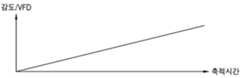
도 3은 APS어레이의 수평위치에 대한 감도와의 관계를 나타내는 그래프이다.3 is a graph showing the relationship between the sensitivity and the horizontal position of the APS array.
도 4는 본 발명의 일실시예에 따른 CIS형 고체 촬상 소자를 나타내는 블록도이다.4 is a block diagram illustrating a CIS type solid-state imaging device according to an embodiment of the present invention.
도 5는 도 4의 APS 어레이의 단위 픽셀을 나타내는 회로도이다.FIG. 5 is a circuit diagram illustrating a unit pixel of the APS array of FIG. 4.
도 6은 도 4의 축적 시간 콘트롤 드라이버를 구체적으로 나타낸 블록도이다.6 is a block diagram illustrating in detail the accumulation time control driver of FIG. 4.
도 7은 도 4의 고체 촬상 소자에서 APS 어레이의 수평 위치에 대한 축적 시간과의 관계를 나타내는 그래프이다.FIG. 7 is a graph showing a relationship with an accumulation time with respect to a horizontal position of an APS array in the solid state image pickup device of FIG. 4.
도 8은 도 4의 고체 촬상 소자에서 APS 어레이의 축적 시간에 대한 감도/영상신호와의 관계를 나타내는 그래프이다.FIG. 8 is a graph illustrating a relationship between a sensitivity / video signal and an accumulation time of an APS array in the solid state image pickup device of FIG. 4.
도 9는 도 4의 고체 촬상 소자에서 APS 어레이의 수평 위치에 대한 감도와의 관계를 나타내는 그래프이다.FIG. 9 is a graph illustrating a relationship between sensitivity to a horizontal position of an APS array in the solid state image pickup device of FIG. 4.
도 10은 도 4의 축적 시간 콘트롤 드라이버의 동작 설명을 위한 타이밍도이다.FIG. 10 is a timing diagram for describing an operation of the accumulation time control driver of FIG. 4.
도 11은 도 10에 따른 APS 어레이의 수평 위치에 대한 축적 시간과의 관계를 나타내는 그래프이다.FIG. 11 is a graph illustrating a relationship with an accumulation time for a horizontal position of the APS array according to FIG. 10.
본 발명은 고체 촬상 소자(solid state image sensing device)에 관한 것으로, 특히 CIS(CMOS Image Sensor) 형 고체 촬상 소자에 관한 것이다.BACKGROUND OF THE INVENTION 1. Field of the Invention The present invention relates to a solid state image sensing device, and more particularly to a CMOS image sensor (CIS) type solid state imaging device.
CIS형 고체 촬상 소자는 휴대폰 카메라, 디지털 스틸 카메라(digital still camera) 등에 장착되어, 시야에 전개되는 영상을 촬상하여 전기적 신호로 변환하여, 디지털 신호 처리부로 전송한다. 디지털 신호 처리부는 고체 촬상 소자에서 출력되는 컬러 이미지 데이터(R, G, B)를 신호처리하여 LCD(liquid crystal display)와 같은 디스플레이 장치를 구동한다.The CIS-type solid-state imaging device is mounted on a mobile phone camera, a digital still camera, or the like, and captures an image developed in a field of view, converts the image into an electrical signal, and transmits it to a digital signal processor. The digital signal processing unit processes color image data R, G, and B output from the solid state image pickup device to drive a display device such as a liquid crystal display (LCD).
도 1은 일반적인 CIS형 고체 촬상 소자(100)를 나타내는 블록도이다. 도 1을 참조하면, 일반적인 CIS형 고체 촬상 소자(100)는 APS(active pixel sensor) 어레이(110), 로우(row) 드라이버(120), 및 아날로그-디지털 변환부(ADC: analog-digital converter)(130)를 구비한다. 로우 드라이버(120)는 로우 디코더(미도시) 에서 제어 신호를 받고, 아날로그-디지털 변환부(130)는 열(column) 디코더(미도시)에서 제어 신호를 받는다. 이외에 상기 고체 촬상 소자(100)는 전반적인 타이밍제어 신호들과 각 픽셀의 선택 및 감지된 영상신호의 출력을 위한 어드레싱(addressing) 신호들을 생성하는 콘트롤부(미도시)를 구비한다. 통상적으로 칼라 고체 촬상 소자(100)인 경우에, APS 어레이(110)를 이루는 각 픽셀 상부에 특정 컬러의 빛만 받아들이도록 컬러 필터(color filter)를 설치하는데, 색 신호를 구성하기 위하여 적어도 3 가지 종류의 컬러 필터를 배치한다. 가장 일반적인 컬러 필터 어레이는 한 행에 R(red), G(green) 2 가지 컬러의 패턴, 및 다른 행에 G(green), B(blue) 2 가지 컬러의 패턴이 반복적으로 배치되는 베이어(Bayer) 패턴을 가진다. 이때, 휘도 신호와 밀접한 관련이 있는 G(green)는 모든 행에 배치되고, R(red) 컬러, B(blue) 컬러는 각 행마다 엇갈리게 배치되어 휘도 해상도를 높인다. 디지털 스틸 카메라 등에는 해상도를 높이기 위하여 100만 픽셀 이상의 많은 픽셀을 배열한 CIS가 적용되어 있다.1 is a block diagram showing a general CIS type solid-
이와 같은 픽셀 구조를 가지는 CIS형 고체 촬상 소자(100)에서, 상기 APS 어레이(110)는 광소자(photodiode)를 이용하여 빛을 감지하여 전기적 신호로 변환하여 영상신호를 생성한다. 상기 APS 어레이(110)에서 출력되는 영상신호는 R(red), G(green), B(blue) 3색의 아날로그 신호이다. 아날로그-디지털 변환부(130)는 상기 픽셀 어레이(110)에서 출력되는 아날로그 영상신호를 받아 디지털 신호로 변환한다.In the CIS type solid-
도 1과 같은 일반적인 CIS형 고체 촬상 소자(100)에서, 광소자에서 감지된 영상신호를 아날로그-디지털 변환부(130)에서 디지털 신호로 변환할 때, CDS(correlated double sampling) 방식을 이용한다. 이와 같은 구동 방식에 대하여는 미국 특허, "USP5,982,318", 또는 "USP6,067,113" 등에 잘 나타나 있다. CDS 방식의 아날로그-디지털 변환에서는 기본적으로 픽셀 어레이(110)에서 리셋신호를 받은 후, 광소자에서 감지된 영상신호를 받아 디지털 신호로 변환하는 두 단계로 구분된다. 광소자에서 소정 주기로 빛을 새로이 감지할 때마다, 광소자가 새로이 감지된 영상신호를 아날로그-디지털 변환부(130)로 출력하기 전에, 픽셀 어레이(110)는 아날로그-디지털 변환부(130)로 리셋신호를 출력한다. 아날로그-디지털 변환부(130)는 리셋신호를 받아 리셋한 후에, 광소자로부터 입력받는 영상신호를 디지털 신호로 변환하여 출력한다. 이와 같이 변환된 디지털 신호는 디지털 신호 처리부로 출력되어 소정 보간(interpolation) 처리된다. 또한, 후속하는 디지털 신호 처리부는 LCD와 같은 디스플레이 장치의 해당 해상도에 적합한 구동 신호들을 생성하여, 디스플레이 장치를 구동한다.In the general CIS type solid-
도 2는 APS 어레이(110)의 수평 위치에 대한 축적 시간과의 관계를 나타내는 그래프이다. 도 2와 같이, 일반적으로, APS 어레이(110)의 수평 위치에 대한 광소자의 축적 시간은 일정하게 설계된다. 도 3은 APS어레이의 수평위치에 대한 감도와의 관계를 나타내는 그래프이다. APS 어레이(110)의 수평 위치에 대한 광소자의 감도(sensitivity)는, 도 3에 도시된 바와 같이, 중심부에 비하여 주변부에서 상대적으로 작게 나타난다. 따라서, 도 2와 같이, 모든 픽셀에서의 광소자의 축적 시간이 일정하면, 공간적으로 APS 어레이(110)의 중심부에서는, 픽셀을 구성하는 광소자가 빛을 많이 받아들여 많은 전하를 축적하고, 주변부 픽셀일수록 광소자가 빛을 적게 받아들여 상대적으로 적은 전하를 축적한다. 이와 같은 종래의 CIS형 고체 촬상 소자(100)에서 출력되는 영상신호에 의하여 디스플레이할 경우에, 디스플레이 장치의 화면상에 중심부는 밝고 주변부는 상대적으로 어둡게 보이는 문제점이 있다. 이와 같은 문제는, 픽셀 수가 352*288인 CIF(Common Intermediate format)의 경우에 작게 나타나지만, 픽셀 수가 1280*1024인 SXGA(Super Extended Graphics Adaptor)의 경우는 심각하고, 해상도가 증가할 수록 이러한 문제는 더 심해진다.2 is a graph showing the relationship with the accumulation time with respect to the horizontal position of the
이와 같이 나타나는 중심부와 주변부 사이의 밝기 차이를 해소하기 위하여, APS 어레이(110)의 픽셀 설계와 공정 콘트롤에 의존하는 것은 한계가 있으며, 아날로그-디지털 변환부(130) 내에 PGA(Programmable Gain Amplifier)를 사용하거나 아날로그-디지털 변환부(130)의 출력 신호를 ISP(Image Digital Signal Processor)에서 보상하는 방법이 시도되고 있다. 그러나, 이와 같이 신호 처리하는 경우에도 양자화 잡음은 증가하므로, 화면상에 깜박 거림등 다른 문제점을 야기한다.In order to resolve the brightness difference between the central portion and the peripheral portion, it is limited to rely on the pixel design and process control of the
따라서, 본 발명이 이루고자하는 기술적 과제는, 양자화 잡음은 증가시키지 않으면서, 디스플레이 화면의 밝기가 전체적으로 고르게 나타나도록, APS 어레이의 에지(edge)부분의 SNR(signal to noise)이나 감도(sensitivity)의 감소 없이, 중심부와 주변부가 유니폼한 레벨을 가지는 영상신호를 출력할 수 있는 고체 촬상 소자를 제공하는 데 있다.Accordingly, the technical problem to be achieved by the present invention is that the signal to noise (SNR) or the sensitivity of the edge portion of the APS array can be uniformly displayed without increasing the quantization noise. The present invention provides a solid-state imaging device capable of outputting a video signal having a uniform level in a central portion and a peripheral portion thereof.
디스플레이 화면의 밝기가 전체적으로 고르게 나타나도록 APS 어레이의 중심 부와 주변부가 유니폼한 레벨을 가지는 영상신호를 출력할 수 있는 고체 촬상 소자 구동 방법을 제공하는 데 있다.The present invention provides a method for driving a solid-state image pickup device capable of outputting an image signal having a uniform level at a central portion and a peripheral portion of an APS array so that brightness of a display screen is evenly distributed.
상기의 기술적 과제를 달성하기 위한 본 발명에 따른 고체 촬상 소자는, APS 어레이, 로우 드라이버, 축적 시간 콘트롤 드라이버, 및 아날로그-디지털 변환부를 구비하는 것을 특징으로 한다. 상기 APS 어레이는 2차원 행렬형태로 픽셀들이 배열되어 있고, 선택된 행에서, 전달 제어 신호에 응답하여 광소자로부터 광전 변환된 영상신호를 출력하고, 리셋 제어 신호에 응답하여 리셋신호를 생성하여 출력한다. 상기 로우 드라이버는 순차적으로 액티브되는 행 선택신호를 생성하여 상기 APS 어레이의 각 행을 선택하고, 상기 리셋 제어 신호를 생성한다. 상기 축적 시간 콘트롤 드라이버는 상기 광소자들의 축적 시간을 일정하지 않게 설정한 상기 전달 제어 신호를 생성한다. 상기 아날로그-디지털 변환부는 상기 리셋신호에 대한 상기 영상신호의 차이에 대응하는 아날로그 신호를 디지털 신호로 변환하여 출력한다.A solid-state imaging device according to the present invention for achieving the above technical problem is characterized by comprising an APS array, a row driver, a storage time control driver, and an analog-to-digital converter. In the APS array, pixels are arranged in a two-dimensional matrix, and in a selected row, the APS array outputs a photoelectrically converted image signal from an optical device in response to a transfer control signal, and generates and outputs a reset signal in response to a reset control signal. . The row driver generates row selection signals that are sequentially activated to select each row of the APS array, and generates the reset control signal. The accumulation time control driver generates the transfer control signal in which the accumulation time of the optical elements is set to be not constant. The analog-digital converter converts an analog signal corresponding to the difference of the video signal with respect to the reset signal into a digital signal and outputs the digital signal.
상기 축적 시간 콘트롤 드라이버는, 상기 APS 어레이가 다수 행씩 분류된 다수 개의 그룹들에 대하여 서로 다른 형태로 설정한 상기 전달 제어 신호를 생성하고, 상기 선택된 행에 해당하는 그룹의 각 행의 광소자들의 축적 시간은 일정하지 않고 상기 해당 그룹 내에서 같은 열에 배열된 광소자들의 축적 시간은 모두 같게 설정한 상기 전달 제어 신호를 생성하는 것을 특징으로 한다. 상기 축적 시간 콘트롤 드라이버는, 상기 해당 그룹의 각 행의 광소자들의 축적 시간이 중심부에서 양주변부로 갈수록 점점 커지게 설정한 상기 전달 제어 신호를 생성하는 것을 특징으 로 한다. 상기 축적 시간 콘트롤 드라이버는, 상기 APS 어레이가 분류된 그룹들에 대하여, 중심 행을 기준으로 대칭되는 위치에 배열된 광소자들의 축적 시간은 모두 같게 설정한 상기 전달 제어 신호를 생성하는 것을 특징으로 한다.The accumulation time control driver generates the transfer control signal in which the APS array is set in a different form for a plurality of groups classified by a plurality of rows, and accumulates optical elements in each row of a group corresponding to the selected row. The time is not constant, and the transfer control signal is generated in which the accumulation time of the optical elements arranged in the same column in the corresponding group is set to be the same. The accumulation time control driver is configured to generate the transfer control signal in which the accumulation time of the optical elements in each row of the corresponding group is set to increase gradually from the central portion to both peripheral portions. The accumulation time control driver is configured to generate the transfer control signal in which the accumulation times of optical elements arranged at positions symmetrical with respect to a center row are set to the groups classified by the APS array. .
상기 축적 시간 콘트롤 드라이버는, 카운터, 레지스터, 및 전달 제어 신호 생성 로직을 구비하는 것을 특징으로 한다. 상기 카운터는 수직 동기 신호에 동기된 시스템 클럭을 카운트하여 상기 APS 어레이의 행 번호를 알리는 행 번호 정보를 생성한다. 상기 레지스터는 상기 행 번호 정보를 이용하여 해당 행의 곡률 정보를 생성한다. 상기 전달 제어 신호 생성 로직은 상기 곡률 정보를 이용하여 상기 전달 제어 신호를 생성한다.The accumulation time control driver is characterized by having a counter, a register, and transfer control signal generation logic. The counter counts a system clock synchronized with a vertical synchronization signal to generate row number information indicating the row number of the APS array. The register generates curvature information of a corresponding row using the row number information. The transfer control signal generation logic generates the transfer control signal using the curvature information.
상기의 다른 기술적 과제를 달성하기 위한 본 발명에 따른 고체 촬상 소자 구동 방법은, 순차적으로 액티브되는 행 선택신호를 생성하여 상기 APS 어레이의 각 행을 선택하는 단계; 리셋 제어 신호를 생성하는 단계; 2차원 행렬형태로 픽셀들이 배열되어 있는 APS 어레이의 광소자들의 축적 시간을 일정하지 않게 설정한 전달 제어 신호를 생성하는 단계; 상기 APS 어레이의 선택된 행에서, 상기 전달 제어 신호에 응답하여 광소자로부터 광전 변환된 영상신호를 출력하고, 상기 리셋 제어 신호에 응답하여 리셋신호를 생성하여 출력하는 단계; 및 상기 리셋신호에 대한 상기 영상신호의 차이에 대응하는 아날로그 신호를 디지털 신호로 변환하여 출력하는 단계를 구비하는 것을 특징으로 한다.According to another aspect of the present invention, there is provided a method of driving a solid-state imaging device, the method comprising: generating a row selection signal that is sequentially activated to select each row of the APS array; Generating a reset control signal; Generating a transmission control signal in which the accumulation time of the optical elements of the APS array in which the pixels are arranged in a two-dimensional matrix form is not set constantly; In a selected row of the APS array, outputting a photoelectrically converted image signal from an optical device in response to the transfer control signal, and generating and outputting a reset signal in response to the reset control signal; And converting an analog signal corresponding to the difference of the video signal with respect to the reset signal into a digital signal and outputting the digital signal.
본 발명과 본 발명의 동작상의 이점 및 본 발명의 실시에 의하여 달성되는 목적을 충분히 이해하기 위해서는 본 발명의 바람직한 실시예를 예시하는 첨부 도 면 및 첨부 도면에 기재된 내용을 참조하여야만 한다.In order to fully understand the present invention, the operational advantages of the present invention, and the objects achieved by the practice of the present invention, reference should be made to the accompanying drawings which illustrate preferred embodiments of the present invention and the contents described in the accompanying drawings.
이하, 첨부한 도면을 참조하여 본 발명의 바람직한 실시예를 설명함으로써, 본 발명을 상세히 설명한다. 각 도면에 제시된 동일한 참조부호는 동일한 부재를 나타낸다.Hereinafter, exemplary embodiments of the present invention will be described in detail with reference to the accompanying drawings. Like reference numerals in the drawings denote like elements.
도 4는 본 발명의 일실시예에 따른 CIS형 고체 촬상 소자(400)를 나타내는 블록도이다. 도 4를 참조하면, 본 발명의 일실시예에 따른 CIS형 고체 촬상 소자(400)는 APS(active pixel sensor) 어레이(410), 로우 드라이버(row driver)(420), 축적 시간 콘트롤 드라이버(integration time control driver)(430), 및 아날로그-디지털 변환부(analog-digital converter)(440)를 구비한다.4 is a block diagram illustrating a CIS type solid-
상기 APS 어레이(410)에는 2차원 행렬형태로 픽셀들이 배열되어 있다. 주지된 바와 같이, 상기 APS 어레이(410)의 픽셀들 각각은 도 5와 같은 회로로 구성된다. 도 5를 참조하면, 상기 APS 어레이(410)는, 행 선택신호(SEL)에 의하여 선택된 행에서, 전달 제어 신호(TX)에 응답하여 광소자(PD:photo diode)로부터 광전 변환된 영상신호(VFD)를 출력하고, 리셋 제어 신호(RX)에 응답하여 리셋신호(VRST)를 생성하여 출력한다. 즉, 도 5에서, 하나의 픽셀은 4개의 MOSFET(metal-oxide-semiconductor field effect transistor)들(M1~M4), 하나의 광소자(PD), 및 바이어스 회로를 모델링하여 나타낸 전류원(CS1)으로 구성된다. 상기 행 선택신호(SEL)가 논리 하이 상태로 액티브된 상태에서, 상기 리셋 제어 신호(RX)가 논리 하이 상태로 액티브되면, 전원(VDD)로부터 전달된 FD 노드의 전압이 소스 폴로워(source follower) 역할을 하는 M3의 소스 단자를 통하여 출력된다. M3의 소스 단자로 출력된 FD 노드의 전압은 M1의 소스 단자를 통하여 리셋신호(VRST)로서 아날로그-디지털 변환부(440)로 출력된다. 실질적으로는 상기 리셋 제어 신호(RX)가 논리 로우 상태로 폴링(falling)할 때, 클럭 피드 쓰루우(clock feed through) 등의 영향을 받아 FD 노드의 전압보다 약간 작아진 전압이 리셋신호(VRST)로 될 수 있다. 한편, 상기 전달 제어 신호(TX)가 논리 하이 상태로 액티브될 때에는, 상기 리셋 제어 신호(RX)가 논리 로우 상태로 된 상태이며, 이때에는 광소자(PD)로부터 광전 변환된 영상신호(VFD)가 M1의 소스 단자를 통하여 아날로그-디지털 변환부(440)로 출력된다.In the
상기 로우 드라이버(420)는 순차적으로 액티브되는 행 선택신호(SEL)를 생성하여 상기 APS 어레이(410)의 각 행을 선택하고, 상기 리셋 제어 신호(RX)를 생성한다.The
상기 축적 시간 콘트롤 드라이버(430)는 상기 광소자들(PD)의 축적 시간을 일정하지 않게 설정한 상기 전달 제어 신호(TX)를 생성한다. 즉, 본 발명의 일실시예에서는 디스플레이 화면의 밝기가 중심부와 주변부 전체적으로 고르게 나타나도록 하기위하여, APS 어레이(410)의 광소자들(PD)의 축적 시간이 모두 일정한 것은 아니고, 주변부의 광소자들(PD)의 축적 시간이 길게 설정된 전달 제어 신호(TX)를 생성하는 상기 축적 시간 콘트롤 드라이버(430)를 제안하였다. 즉, 디스플레이 화면의 밝기는 주변부, 즉, 상기 APS 어레이(410)의 모서리 부분쪽에 대응하는 위치에서 중심부에 비하여 상대적으로 어둡게 나타난다. 따라서, 상기 APS 어레이(410) 의 모서리 부분쪽에 배열된 광소자들(PD)의 축적 시간을 길게 설정함으로써, 디스플레이 화면의 밝기가 전체적으로 고르게 나타나도록 할 수 있다. 그런데, 이와 같이 상기 APS 어레이(410)의 모서리 부분쪽의 축적 시간을 상대적으로 길게 콘트롤하기 위하여, 행마다 광소자들(PD)이 서로 다른 축적 시간을 갖도록 하기 위하여는 상기 축적 시간 콘트롤 드라이버(430)의 하드웨어를 너무 복잡하게 한다. 따라서, 본 발명의 일실시예에서는 도 4에 도시된 바와 같이, 상기 APS 어레이(410)를 다수 행씩 다수개의 그룹들(A, B, C, D)로 분류하고, 광소자들(PD)이 서로 다른 축적 시간을 갖도록 콘트롤한다. 도 4에서, 상기 APS 어레이(410)는 4 개의 그룹들(A, B, C, D)로 분류되었으나, 더 많은 그룹이 존재할 수 있고, 그 그룹의 수는 홀수개이든 짝수개 이든 무관하다. 그룹들(A, B, C, D) 각각에서, 하나의 그룹 내의 모든 행에 대하여 같은 형태로 축적 시간 콘트롤이 이루어지며, 하나의 그룹 내의 열들에 대해서는 서로 다른 축적 시간을 갖도록 축적 시간 콘트롤이 이루어진다. 이와 같은, 축적 시간 콘트롤에 대해서는, 도 6 내지 도 11의 설명에서 더 자세히 기술된다.The accumulation
한편, 상기 아날로그-디지털 변환부(440)는, CDS(correlated double sampling) 방식에 따라, 상기 리셋신호(VRST)에 대한 상기 영상신호(VFD)의 차이에 대응하는 아날로그 신호를 디지털 신호로 변환하여 출력한다. 이와 같이 변환된 디지털 신호는 디지털 신호 처리부로 출력되어 소정 보간(interpolation) 처리된다. 또한, 후속하는 디지털 신호 처리부는 LCD와 같은 디스플레이 장치의 해당 해상도에 적합한 구동 신호들을 생성하여, 디스플레이 장치를 구동한다.The analog-
도 6은 도 4의 축적 시간 콘트롤 드라이버(430)를 구체적으로 나타낸 블록도이다. 도 6을 참조하면, 상기 축적 시간 콘트롤 드라이버(430)는, 카운터(431), 레지스터(432), 및 전달 제어 신호 생성 로직(433)을 구비한다.6 is a block diagram illustrating in detail the accumulation
상기 카운터(431)는 수직 동기 신호(VS)에 동기된 시스템 클럭(SCLK)을 카운트하여 상기 APS 어레이(410)의 행 번호를 알리는 행 번호 정보(ROWNUM)를 생성한다. 상기 수직 동기 신호(VS)는 한 화면, 즉, 한 프레임 기간을 알리는 신호이다. 반면, 도 4에서 상기 행 선택신호(SEL)는 각 행의 리셋신호(VRST)와 영상신호(VFD)를 전달하기 위하여 매 행을 선택할 때마다 액티브 되는 신호이다. 시스템 클럭(SCLK)은 상기 행 선택신호(SEL)를 생성할 때에도 사용되고, 상기 행 선택신호(SEL)에 동기되어 있다.The
상기 레지스터(432)는 상기 행 번호 정보(ROWNUM)를 이용하여 해당 행의 곡률 정보(CVD:cavature data)를 생성한다. 예를 들어, 상기 곡률 정보(CVD)는 도 4와 같이, 상기 APS 어레이(410)가 4개의 그룹들(A, B, C, D)로 분류된 경우에, 도 7과 같이, 각 그룹마다 APS 어레이(410)의 수평 위치에 대한 축적 시간을 알리는 정보이다. 도 7에서, X는 APS 어레이(410)의 왼 쪽 끝 또는 오른 쪽 끝부터의 수평 위치를 나타낸다. 즉, 도 7에서, 도 4의 (A), 및 (D) 그룹은 (B), 및 (C) 그룹에 비하여 APS 어레이(410)의 좌우에서 좀더 긴 축적 시간을 가진다. 이는 APS 어레이(410)의 모서리 부분쪽에 대응하는 디스플레이 화면이 중앙쪽 좌우에 비하여 더 어둡게 나타나기 때문에, 이를 보상해주기 위함이다.The
이와 같이, 상기 곡률 정보(CVD)를 이용하는 것은, 축적 시간에 대한 광소자(PD)의 감도 및 영상신호(VFD)의 관계가 도 8과 같이 나타나기 때문에 가능하다. 즉, 축적 시간이 커질수록 광소자(PD)의 감도 및 영상신호(VFD)는 커진다. 따라서, 광소자(PD)의 축적 시간을 증가시킴으로써, PGA(Programmable Gain Amplifier)에서 게인(gain)을 증가시켜 출력 전압을 키우는 것과 같은 역할을 할 수 있다는 것을 의미한다.As described above, the use of the curvature information CVD is possible because the relationship between the sensitivity of the optical element PD and the image signal VFD with respect to the accumulation time is shown as shown in FIG. 8. That is, as the accumulation time increases, the sensitivity of the optical device PD and the image signal VFD increase. Therefore, by increasing the accumulation time of the optical device (PD), it means that it is possible to increase the gain in the PGA (programmable gain amplifier) to increase the output voltage.
이와 같은 관계에 따라, 상기 전달 제어 신호 생성 로직(433)은 상기 곡률 정보(CVD)를 이용하여, 그룹들(A, B, C, D) 각각에 대하여 일정하지 않은 전달 제어 신호(TX)를 생성한다. 즉, 위에서 기술한 바와 같이, 상기 전달 제어 신호(TX)는 하나의 그룹 내의 모든 행이 같은 형태로 축적 시간을 갖도록 설정되며, 하나의 그룹 내의 열들에 대해서는 서로 다르게 축적 시간을 갖도록 설정된다. 상기 APS 어레이(410)가 다수 행씩 분류된 다수 개의 그룹들(A, B, C, D) 각각에 대해서는, 상기 전달 제어 신호(TX)가 서로 다른 형태로 설정된다. 이와 같이, 상기 전달 제어 신호(TX)가 생성되는 경우에, APS 어레이(410)의 수평 위치에 대한 감도와의 관계는 도 9와 같이, 일정하게 된다. 따라서, APS 어레이(410)의 중심부와 주변부에 대응하는 디스플레이 화면의 밝기가 고르게 나타난다.According to this relationship, the transfer control
이하, 도 4의 축적 시간 콘트롤 드라이버(430)의 동작을 좀더 상세하게 설명한다.Hereinafter, the operation of the accumulation
도 10은 도 4의 축적 시간 콘트롤 드라이버(430)의 동작 설명을 위한 타이밍도이다. 도 10을 참조하면, 축적 시간 콘트롤 드라이버(430)의 상기 전달 제어 신호 생성 로직(433)은 그룹들(A, B, C, D) 각각에 대하여, 각 열에 따라 서로 다른 전달 제어 신호(TX)를 생성하여 출력한다. 즉, 상기 축적 시간 콘트롤 드라이버(430)의 상기 전달 제어 신호 생성 로직(433)은, 해당 그룹의 각 행의 광소자들(PD)의 축적 시간이 중심부에서 양주변부로 갈수록 점점 커지게 설정한 상기 전달 제어 신호(TX)를 생성한다. 예를 들어, 도 11과 같은 곡률 정보(CVD)를 가지는 해당 그룹에 대하여, 도 10과 같이 전달 제어 신호(TX)를 생성하면, x1 위치의 픽셀에서는 TX(x1)을 전달 제어 신호(TX)로서 받아, 해당 광소자(PD)는 T1 기간 동안 빛을 축적하여 광전 변환한다. 마찬가지로, xn 위치의 픽셀에서는 TX(xn)을 전달 제어 신호(TX)로서 받아, 해당 광소자(PD)는 Tn 기간 동안 빛을 축적하여 광전 변환한다. 이때, 상기 APS 어레이(410)가 도 4와 같이 짝수 개의 그룹들(A, B, C, D)로 분류된 경우에, 중심 행을 기준으로 대칭되는 위치에 배열된 광소자들(PD)의 축적 시간은 모두 같게 설정된다. 상기 APS 어레이(410)가 도 4와 같이 짝수 개의 그룹들(A, B, C, D)로 분류된 경우에, 중심 행을 기준으로 대칭되는 그룹들의 곡률 정보(CVD)는 같기 때문이다.10 is a timing diagram for describing an operation of the accumulation
또한, 상기 APS 어레이(410)가 홀수 개의 그룹들로 분류된 경우에도, 중심 행을 기준으로 대칭되는 위치에 배열된 광소자들(PD)의 축적 시간은 모두 같게 설정된다. 즉, 상기 APS 어레이(410)가 홀수 개의 그룹들로 분류된 경우에, 중심 픽셀 주위의 중심 그룹에서는, 각 행의 광소자들(PD)의 축적 시간은 일정하지 않고, 그 해당 그룹 내에서 같은 열에 배열된 광소자들(PD)의 축적 시간은 모두 같게 설정된다. 따라서, 중심 그룹에서는 같은 열에 배열된 광소자들(PD)의 축적 시간이 모두 같으므로, 중심 행을 기준으로 대칭되는 위치에 배열된 광소자들(PD)의 축적 시간은 모두 같다. 또한, 중심 그룹이외의 그룹들에서도, 중심 행을 기준으로 대칭되는 그룹들의 곡률 정보(CVD)는 같게 설정되고, 이에 따라 중심 행을 기준으로 대칭되는 위치에 배열된 광소자들(PD)의 축적 시간이 모두 같도록 설정된다.In addition, even when the
위에서 기술한 바와 같이, 본 발명의 일실시예에 따른 고체 촬상 소자(400)는, APS 어레이(410)의 열 및 행에서 광소자(PD)의 축적 시간을 중심부는 짧게 하고 주변부로 갈수록 길게 변화를 주어, 전체 픽셀에서 광소자(PD)의 감도가 일정하고, 광소자(PD)에서 감지된 영상신호(VFD)의 크기가 유니폼(uniform)하게 출력된다. 따라서, APS 어레이(410)의 중심부와 주변부에서 출력되는 영상신호(VFD) 레벨의 상대적인 차이가 없어지고, 에지(edge)부분의 SNR(signal to noise)이나 감도(sensitivity)의 감소를 해소할 수 있다.As described above, the solid-
이상에서와 같이 도면과 명세서에서 최적 실시예가 개시되었다. 여기서 특정한 용어들이 사용되었으나, 이는 단지 본 발명을 설명하기 위한 목적에서 사용된 것이지 의미한정이나 특허청구범위에 기재된 본 발명의 범위를 제한하기 위하여 사용된 것은 아니다. 그러므로 본 기술 분야의 통상의 지식을 가진 자라면 이로부터 다양한 변형 및 균등한 타 실시예가 가능하다는 점을 이해할 것이다. 따라서, 본 발명의 진정한 기술적 보호 범위는 첨부된 특허청구범위의 기술적 사상에 의해 정해져야 할 것이다.As described above, optimal embodiments have been disclosed in the drawings and the specification. Although specific terms have been used herein, they are used only for the purpose of describing the present invention and are not intended to limit the scope of the present invention as defined in the claims or the claims. Therefore, those skilled in the art will understand that various modifications and equivalent other embodiments are possible from this. Therefore, the true technical protection scope of the present invention will be defined by the technical spirit of the appended claims.
상술한 바와 같이 본 발명에 따른 고체 촬상 소자는, 양자화 잡음이 없이 APS 어레이의 중심부와 주변부가 유니폼한 레벨을 가지는 영상신호를 출력할 수 있다. 따라서, 디스플레이 화면 밝기가 전체적으로 고르게 나타나는 효과가 있다.As described above, the solid-state imaging device according to the present invention can output an image signal having a uniform level at the center and the periphery of the APS array without quantization noise. Therefore, there is an effect that the display screen brightness appears evenly as a whole.
Claims (14)
Translated fromKoreanPriority Applications (4)
| Application Number | Priority Date | Filing Date | Title |
|---|---|---|---|
| KR1020040008255AKR100855957B1 (en) | 2004-02-09 | 2004-02-09 | Solid-state image sensor and its driving method for compensating the brightness of the periphery of the screen |
| US11/007,707US7193199B2 (en) | 2004-02-09 | 2004-12-08 | Solid-state image-sensing device that compensates for brightness at edges of a display area and a driving method thereof |
| JP2005028150AJP4740607B2 (en) | 2004-02-09 | 2005-02-03 | Solid-state imaging device and driving method thereof |
| US11/673,846US20070126900A1 (en) | 2004-02-09 | 2007-02-12 | Solid-state image-sensing device that compensates for brightness at edges of a display area and a driving method thereof |
Applications Claiming Priority (1)
| Application Number | Priority Date | Filing Date | Title |
|---|---|---|---|
| KR1020040008255AKR100855957B1 (en) | 2004-02-09 | 2004-02-09 | Solid-state image sensor and its driving method for compensating the brightness of the periphery of the screen |
Publications (2)
| Publication Number | Publication Date |
|---|---|
| KR20050080236A KR20050080236A (en) | 2005-08-12 |
| KR100855957B1true KR100855957B1 (en) | 2008-09-02 |
Family
ID=34825126
Family Applications (1)
| Application Number | Title | Priority Date | Filing Date |
|---|---|---|---|
| KR1020040008255AExpired - Fee RelatedKR100855957B1 (en) | 2004-02-09 | 2004-02-09 | Solid-state image sensor and its driving method for compensating the brightness of the periphery of the screen |
Country Status (3)
| Country | Link |
|---|---|
| US (2) | US7193199B2 (en) |
| JP (1) | JP4740607B2 (en) |
| KR (1) | KR100855957B1 (en) |
Families Citing this family (400)
| Publication number | Priority date | Publication date | Assignee | Title |
|---|---|---|---|---|
| US20070084897A1 (en) | 2003-05-20 | 2007-04-19 | Shelton Frederick E Iv | Articulating surgical stapling instrument incorporating a two-piece e-beam firing mechanism |
| US9060770B2 (en) | 2003-05-20 | 2015-06-23 | Ethicon Endo-Surgery, Inc. | Robotically-driven surgical instrument with E-beam driver |
| US11998198B2 (en) | 2004-07-28 | 2024-06-04 | Cilag Gmbh International | Surgical stapling instrument incorporating a two-piece E-beam firing mechanism |
| US11890012B2 (en) | 2004-07-28 | 2024-02-06 | Cilag Gmbh International | Staple cartridge comprising cartridge body and attached support |
| US8215531B2 (en) | 2004-07-28 | 2012-07-10 | Ethicon Endo-Surgery, Inc. | Surgical stapling instrument having a medical substance dispenser |
| US9072535B2 (en) | 2011-05-27 | 2015-07-07 | Ethicon Endo-Surgery, Inc. | Surgical stapling instruments with rotatable staple deployment arrangements |
| US7669746B2 (en) | 2005-08-31 | 2010-03-02 | Ethicon Endo-Surgery, Inc. | Staple cartridges for forming staples having differing formed staple heights |
| US11484312B2 (en) | 2005-08-31 | 2022-11-01 | Cilag Gmbh International | Staple cartridge comprising a staple driver arrangement |
| US9237891B2 (en) | 2005-08-31 | 2016-01-19 | Ethicon Endo-Surgery, Inc. | Robotically-controlled surgical stapling devices that produce formed staples having different lengths |
| US10159482B2 (en) | 2005-08-31 | 2018-12-25 | Ethicon Llc | Fastener cartridge assembly comprising a fixed anvil and different staple heights |
| US7934630B2 (en) | 2005-08-31 | 2011-05-03 | Ethicon Endo-Surgery, Inc. | Staple cartridges for forming staples having differing formed staple heights |
| US11246590B2 (en) | 2005-08-31 | 2022-02-15 | Cilag Gmbh International | Staple cartridge including staple drivers having different unfired heights |
| US20070106317A1 (en) | 2005-11-09 | 2007-05-10 | Shelton Frederick E Iv | Hydraulically and electrically actuated articulation joints for surgical instruments |
| US8186555B2 (en) | 2006-01-31 | 2012-05-29 | Ethicon Endo-Surgery, Inc. | Motor-driven surgical cutting and fastening instrument with mechanical closure system |
| US20120292367A1 (en) | 2006-01-31 | 2012-11-22 | Ethicon Endo-Surgery, Inc. | Robotically-controlled end effector |
| US8708213B2 (en) | 2006-01-31 | 2014-04-29 | Ethicon Endo-Surgery, Inc. | Surgical instrument having a feedback system |
| US11793518B2 (en) | 2006-01-31 | 2023-10-24 | Cilag Gmbh International | Powered surgical instruments with firing system lockout arrangements |
| US7845537B2 (en) | 2006-01-31 | 2010-12-07 | Ethicon Endo-Surgery, Inc. | Surgical instrument having recording capabilities |
| US20110295295A1 (en) | 2006-01-31 | 2011-12-01 | Ethicon Endo-Surgery, Inc. | Robotically-controlled surgical instrument having recording capabilities |
| US20110024477A1 (en) | 2009-02-06 | 2011-02-03 | Hall Steven G | Driven Surgical Stapler Improvements |
| US8820603B2 (en) | 2006-01-31 | 2014-09-02 | Ethicon Endo-Surgery, Inc. | Accessing data stored in a memory of a surgical instrument |
| US11278279B2 (en) | 2006-01-31 | 2022-03-22 | Cilag Gmbh International | Surgical instrument assembly |
| US11224427B2 (en) | 2006-01-31 | 2022-01-18 | Cilag Gmbh International | Surgical stapling system including a console and retraction assembly |
| US7753904B2 (en) | 2006-01-31 | 2010-07-13 | Ethicon Endo-Surgery, Inc. | Endoscopic surgical instrument with a handle that can articulate with respect to the shaft |
| US8992422B2 (en) | 2006-03-23 | 2015-03-31 | Ethicon Endo-Surgery, Inc. | Robotically-controlled endoscopic accessory channel |
| KR20070099942A (en) | 2006-04-06 | 2007-10-10 | 삼성전자주식회사 | LCD Display |
| US8322455B2 (en) | 2006-06-27 | 2012-12-04 | Ethicon Endo-Surgery, Inc. | Manually driven surgical cutting and fastening instrument |
| US10568652B2 (en) | 2006-09-29 | 2020-02-25 | Ethicon Llc | Surgical staples having attached drivers of different heights and stapling instruments for deploying the same |
| US11980366B2 (en) | 2006-10-03 | 2024-05-14 | Cilag Gmbh International | Surgical instrument |
| US8632535B2 (en) | 2007-01-10 | 2014-01-21 | Ethicon Endo-Surgery, Inc. | Interlock and surgical instrument including same |
| US8684253B2 (en) | 2007-01-10 | 2014-04-01 | Ethicon Endo-Surgery, Inc. | Surgical instrument with wireless communication between a control unit of a robotic system and remote sensor |
| US11291441B2 (en) | 2007-01-10 | 2022-04-05 | Cilag Gmbh International | Surgical instrument with wireless communication between control unit and remote sensor |
| US20080169333A1 (en) | 2007-01-11 | 2008-07-17 | Shelton Frederick E | Surgical stapler end effector with tapered distal end |
| US11039836B2 (en) | 2007-01-11 | 2021-06-22 | Cilag Gmbh International | Staple cartridge for use with a surgical stapling instrument |
| US7673782B2 (en) | 2007-03-15 | 2010-03-09 | Ethicon Endo-Surgery, Inc. | Surgical stapling instrument having a releasable buttress material |
| EP1971129A1 (en)* | 2007-03-16 | 2008-09-17 | STMicroelectronics (Research & Development) Limited | Improvements in or relating to image sensors |
| US11564682B2 (en) | 2007-06-04 | 2023-01-31 | Cilag Gmbh International | Surgical stapler device |
| US8931682B2 (en) | 2007-06-04 | 2015-01-13 | Ethicon Endo-Surgery, Inc. | Robotically-controlled shaft based rotary drive systems for surgical instruments |
| US7753245B2 (en) | 2007-06-22 | 2010-07-13 | Ethicon Endo-Surgery, Inc. | Surgical stapling instruments |
| US11849941B2 (en) | 2007-06-29 | 2023-12-26 | Cilag Gmbh International | Staple cartridge having staple cavities extending at a transverse angle relative to a longitudinal cartridge axis |
| US9285670B2 (en)* | 2007-09-14 | 2016-03-15 | Capso Vision, Inc. | Data communication between capsulated camera and its external environments |
| US8758391B2 (en) | 2008-02-14 | 2014-06-24 | Ethicon Endo-Surgery, Inc. | Interchangeable tools for surgical instruments |
| US11986183B2 (en) | 2008-02-14 | 2024-05-21 | Cilag Gmbh International | Surgical cutting and fastening instrument comprising a plurality of sensors to measure an electrical parameter |
| US9179912B2 (en) | 2008-02-14 | 2015-11-10 | Ethicon Endo-Surgery, Inc. | Robotically-controlled motorized surgical cutting and fastening instrument |
| US7866527B2 (en) | 2008-02-14 | 2011-01-11 | Ethicon Endo-Surgery, Inc. | Surgical stapling apparatus with interlockable firing system |
| US7819298B2 (en) | 2008-02-14 | 2010-10-26 | Ethicon Endo-Surgery, Inc. | Surgical stapling apparatus with control features operable with one hand |
| US8636736B2 (en) | 2008-02-14 | 2014-01-28 | Ethicon Endo-Surgery, Inc. | Motorized surgical cutting and fastening instrument |
| JP5410110B2 (en) | 2008-02-14 | 2014-02-05 | エシコン・エンド−サージェリィ・インコーポレイテッド | Surgical cutting / fixing instrument with RF electrode |
| US8573465B2 (en) | 2008-02-14 | 2013-11-05 | Ethicon Endo-Surgery, Inc. | Robotically-controlled surgical end effector system with rotary actuated closure systems |
| US9585657B2 (en) | 2008-02-15 | 2017-03-07 | Ethicon Endo-Surgery, Llc | Actuator for releasing a layer of material from a surgical end effector |
| DE102008027188A1 (en)* | 2008-06-06 | 2009-12-10 | Volkswagen Ag | Image acquisition unit for detecting e.g. color information, has light sensors that act as intensity and color sensors, where number of intensity sensors is greater than number of color sensors |
| US11648005B2 (en) | 2008-09-23 | 2023-05-16 | Cilag Gmbh International | Robotically-controlled motorized surgical instrument with an end effector |
| US9386983B2 (en) | 2008-09-23 | 2016-07-12 | Ethicon Endo-Surgery, Llc | Robotically-controlled motorized surgical instrument |
| US8210411B2 (en) | 2008-09-23 | 2012-07-03 | Ethicon Endo-Surgery, Inc. | Motor-driven surgical cutting instrument |
| US9005230B2 (en) | 2008-09-23 | 2015-04-14 | Ethicon Endo-Surgery, Inc. | Motorized surgical instrument |
| US8608045B2 (en) | 2008-10-10 | 2013-12-17 | Ethicon Endo-Sugery, Inc. | Powered surgical cutting and stapling apparatus with manually retractable firing system |
| JP5247397B2 (en)* | 2008-12-05 | 2013-07-24 | キヤノン株式会社 | Imaging apparatus and imaging method |
| US8517239B2 (en) | 2009-02-05 | 2013-08-27 | Ethicon Endo-Surgery, Inc. | Surgical stapling instrument comprising a magnetic element driver |
| RU2525225C2 (en) | 2009-02-06 | 2014-08-10 | Этикон Эндо-Серджери, Инк. | Improvement of drive surgical suturing instrument |
| JP5219934B2 (en)* | 2009-06-17 | 2013-06-26 | キヤノン株式会社 | Imaging apparatus and control method thereof |
| US8212197B2 (en)* | 2009-07-02 | 2012-07-03 | Xerox Corporation | Image sensor with integration time compensation |
| US8851354B2 (en) | 2009-12-24 | 2014-10-07 | Ethicon Endo-Surgery, Inc. | Surgical cutting instrument that analyzes tissue thickness |
| US8220688B2 (en) | 2009-12-24 | 2012-07-17 | Ethicon Endo-Surgery, Inc. | Motor-driven surgical cutting instrument with electric actuator directional control assembly |
| US8783543B2 (en) | 2010-07-30 | 2014-07-22 | Ethicon Endo-Surgery, Inc. | Tissue acquisition arrangements and methods for surgical stapling devices |
| US9386988B2 (en) | 2010-09-30 | 2016-07-12 | Ethicon End-Surgery, LLC | Retainer assembly including a tissue thickness compensator |
| US9351730B2 (en) | 2011-04-29 | 2016-05-31 | Ethicon Endo-Surgery, Llc | Tissue thickness compensator comprising channels |
| US11925354B2 (en) | 2010-09-30 | 2024-03-12 | Cilag Gmbh International | Staple cartridge comprising staples positioned within a compressible portion thereof |
| US9629814B2 (en) | 2010-09-30 | 2017-04-25 | Ethicon Endo-Surgery, Llc | Tissue thickness compensator configured to redistribute compressive forces |
| US9788834B2 (en) | 2010-09-30 | 2017-10-17 | Ethicon Llc | Layer comprising deployable attachment members |
| US12213666B2 (en) | 2010-09-30 | 2025-02-04 | Cilag Gmbh International | Tissue thickness compensator comprising layers |
| US10945731B2 (en) | 2010-09-30 | 2021-03-16 | Ethicon Llc | Tissue thickness compensator comprising controlled release and expansion |
| US11812965B2 (en) | 2010-09-30 | 2023-11-14 | Cilag Gmbh International | Layer of material for a surgical end effector |
| US11298125B2 (en) | 2010-09-30 | 2022-04-12 | Cilag Gmbh International | Tissue stapler having a thickness compensator |
| US9016542B2 (en) | 2010-09-30 | 2015-04-28 | Ethicon Endo-Surgery, Inc. | Staple cartridge comprising compressible distortion resistant components |
| US8695866B2 (en) | 2010-10-01 | 2014-04-15 | Ethicon Endo-Surgery, Inc. | Surgical instrument having a power control circuit |
| AU2012250197B2 (en) | 2011-04-29 | 2017-08-10 | Ethicon Endo-Surgery, Inc. | Staple cartridge comprising staples positioned within a compressible portion thereof |
| US11207064B2 (en) | 2011-05-27 | 2021-12-28 | Cilag Gmbh International | Automated end effector component reloading system for use with a robotic system |
| GB2497571A (en) | 2011-12-15 | 2013-06-19 | St Microelectronics Res & Dev | An imaging array with high dynamic range |
| US9044230B2 (en) | 2012-02-13 | 2015-06-02 | Ethicon Endo-Surgery, Inc. | Surgical cutting and fastening instrument with apparatus for determining cartridge and firing motion status |
| JP6224070B2 (en) | 2012-03-28 | 2017-11-01 | エシコン・エンド−サージェリィ・インコーポレイテッドEthicon Endo−Surgery,Inc. | Retainer assembly including tissue thickness compensator |
| MX358135B (en) | 2012-03-28 | 2018-08-06 | Ethicon Endo Surgery Inc | Tissue thickness compensator comprising a plurality of layers. |
| BR112014024098B1 (en) | 2012-03-28 | 2021-05-25 | Ethicon Endo-Surgery, Inc. | staple cartridge |
| US9101358B2 (en) | 2012-06-15 | 2015-08-11 | Ethicon Endo-Surgery, Inc. | Articulatable surgical instrument comprising a firing drive |
| US12383267B2 (en) | 2012-06-28 | 2025-08-12 | Cilag Gmbh International | Robotically powered surgical device with manually-actuatable reversing system |
| BR112014032776B1 (en) | 2012-06-28 | 2021-09-08 | Ethicon Endo-Surgery, Inc | SURGICAL INSTRUMENT SYSTEM AND SURGICAL KIT FOR USE WITH A SURGICAL INSTRUMENT SYSTEM |
| US11278284B2 (en) | 2012-06-28 | 2022-03-22 | Cilag Gmbh International | Rotary drive arrangements for surgical instruments |
| US9289256B2 (en) | 2012-06-28 | 2016-03-22 | Ethicon Endo-Surgery, Llc | Surgical end effectors having angled tissue-contacting surfaces |
| JP6290201B2 (en) | 2012-06-28 | 2018-03-07 | エシコン・エンド−サージェリィ・インコーポレイテッドEthicon Endo−Surgery,Inc. | Lockout for empty clip cartridge |
| US9282974B2 (en) | 2012-06-28 | 2016-03-15 | Ethicon Endo-Surgery, Llc | Empty clip cartridge lockout |
| US9408606B2 (en) | 2012-06-28 | 2016-08-09 | Ethicon Endo-Surgery, Llc | Robotically powered surgical device with manually-actuatable reversing system |
| US20140001231A1 (en) | 2012-06-28 | 2014-01-02 | Ethicon Endo-Surgery, Inc. | Firing system lockout arrangements for surgical instruments |
| BR112015021082B1 (en) | 2013-03-01 | 2022-05-10 | Ethicon Endo-Surgery, Inc | surgical instrument |
| RU2672520C2 (en) | 2013-03-01 | 2018-11-15 | Этикон Эндо-Серджери, Инк. | Hingedly turnable surgical instruments with conducting ways for signal transfer |
| US9629629B2 (en) | 2013-03-14 | 2017-04-25 | Ethicon Endo-Surgey, LLC | Control systems for surgical instruments |
| US9808244B2 (en) | 2013-03-14 | 2017-11-07 | Ethicon Llc | Sensor arrangements for absolute positioning system for surgical instruments |
| JP5665907B2 (en)* | 2013-04-03 | 2015-02-04 | キヤノン株式会社 | Imaging apparatus and imaging method |
| BR112015026109B1 (en) | 2013-04-16 | 2022-02-22 | Ethicon Endo-Surgery, Inc | surgical instrument |
| US9826976B2 (en) | 2013-04-16 | 2017-11-28 | Ethicon Llc | Motor driven surgical instruments with lockable dual drive shafts |
| MX369362B (en) | 2013-08-23 | 2019-11-06 | Ethicon Endo Surgery Llc | Firing member retraction devices for powered surgical instruments. |
| US9775609B2 (en) | 2013-08-23 | 2017-10-03 | Ethicon Llc | Tamper proof circuit for surgical instrument battery pack |
| US9962161B2 (en) | 2014-02-12 | 2018-05-08 | Ethicon Llc | Deliverable surgical instrument |
| US12232723B2 (en) | 2014-03-26 | 2025-02-25 | Cilag Gmbh International | Systems and methods for controlling a segmented circuit |
| US10004497B2 (en) | 2014-03-26 | 2018-06-26 | Ethicon Llc | Interface systems for use with surgical instruments |
| US10013049B2 (en) | 2014-03-26 | 2018-07-03 | Ethicon Llc | Power management through sleep options of segmented circuit and wake up control |
| US20150272580A1 (en) | 2014-03-26 | 2015-10-01 | Ethicon Endo-Surgery, Inc. | Verification of number of battery exchanges/procedure count |
| BR112016021943B1 (en) | 2014-03-26 | 2022-06-14 | Ethicon Endo-Surgery, Llc | SURGICAL INSTRUMENT FOR USE BY AN OPERATOR IN A SURGICAL PROCEDURE |
| US10327764B2 (en) | 2014-09-26 | 2019-06-25 | Ethicon Llc | Method for creating a flexible staple line |
| CN106456159B (en) | 2014-04-16 | 2019-03-08 | 伊西康内外科有限责任公司 | Fastener Cartridge Assembly and Nail Retainer Cover Arrangement |
| BR112016023825B1 (en) | 2014-04-16 | 2022-08-02 | Ethicon Endo-Surgery, Llc | STAPLE CARTRIDGE FOR USE WITH A SURGICAL STAPLER AND STAPLE CARTRIDGE FOR USE WITH A SURGICAL INSTRUMENT |
| US10470768B2 (en) | 2014-04-16 | 2019-11-12 | Ethicon Llc | Fastener cartridge including a layer attached thereto |
| US20150297225A1 (en) | 2014-04-16 | 2015-10-22 | Ethicon Endo-Surgery, Inc. | Fastener cartridges including extensions having different configurations |
| CN106456176B (en) | 2014-04-16 | 2019-06-28 | 伊西康内外科有限责任公司 | Fastener Cartridge Including Extensions With Different Configurations |
| KR20160019215A (en)* | 2014-08-11 | 2016-02-19 | 삼성전자주식회사 | Photographing apparatus and photographing method thereof |
| US11311294B2 (en) | 2014-09-05 | 2022-04-26 | Cilag Gmbh International | Powered medical device including measurement of closure state of jaws |
| BR112017004361B1 (en) | 2014-09-05 | 2023-04-11 | Ethicon Llc | ELECTRONIC SYSTEM FOR A SURGICAL INSTRUMENT |
| US10135242B2 (en) | 2014-09-05 | 2018-11-20 | Ethicon Llc | Smart cartridge wake up operation and data retention |
| US10105142B2 (en) | 2014-09-18 | 2018-10-23 | Ethicon Llc | Surgical stapler with plurality of cutting elements |
| CN107427300B (en) | 2014-09-26 | 2020-12-04 | 伊西康有限责任公司 | Surgical suture buttresses and auxiliary materials |
| US11523821B2 (en) | 2014-09-26 | 2022-12-13 | Cilag Gmbh International | Method for creating a flexible staple line |
| US10076325B2 (en) | 2014-10-13 | 2018-09-18 | Ethicon Llc | Surgical stapling apparatus comprising a tissue stop |
| US9924944B2 (en) | 2014-10-16 | 2018-03-27 | Ethicon Llc | Staple cartridge comprising an adjunct material |
| US10517594B2 (en) | 2014-10-29 | 2019-12-31 | Ethicon Llc | Cartridge assemblies for surgical staplers |
| US11141153B2 (en) | 2014-10-29 | 2021-10-12 | Cilag Gmbh International | Staple cartridges comprising driver arrangements |
| US9844376B2 (en) | 2014-11-06 | 2017-12-19 | Ethicon Llc | Staple cartridge comprising a releasable adjunct material |
| US12401911B2 (en) | 2014-11-07 | 2025-08-26 | Duelight Llc | Systems and methods for generating a high-dynamic range (HDR) pixel stream |
| US12401912B2 (en) | 2014-11-17 | 2025-08-26 | Duelight Llc | System and method for generating a digital image |
| US10736636B2 (en) | 2014-12-10 | 2020-08-11 | Ethicon Llc | Articulatable surgical instrument system |
| MX389118B (en) | 2014-12-18 | 2025-03-20 | Ethicon Llc | SURGICAL INSTRUMENT WITH AN ANVIL THAT CAN BE SELECTIVELY MOVED ON A DISCRETE, NON-MOBILE AXIS RELATIVE TO A STAPLE CARTRIDGE. |
| US9943309B2 (en) | 2014-12-18 | 2018-04-17 | Ethicon Llc | Surgical instruments with articulatable end effectors and movable firing beam support arrangements |
| US9987000B2 (en) | 2014-12-18 | 2018-06-05 | Ethicon Llc | Surgical instrument assembly comprising a flexible articulation system |
| US9844374B2 (en) | 2014-12-18 | 2017-12-19 | Ethicon Llc | Surgical instrument systems comprising an articulatable end effector and means for adjusting the firing stroke of a firing member |
| US10085748B2 (en) | 2014-12-18 | 2018-10-02 | Ethicon Llc | Locking arrangements for detachable shaft assemblies with articulatable surgical end effectors |
| US9844375B2 (en) | 2014-12-18 | 2017-12-19 | Ethicon Llc | Drive arrangements for articulatable surgical instruments |
| US11154301B2 (en) | 2015-02-27 | 2021-10-26 | Cilag Gmbh International | Modular stapling assembly |
| US10548504B2 (en) | 2015-03-06 | 2020-02-04 | Ethicon Llc | Overlaid multi sensor radio frequency (RF) electrode system to measure tissue compression |
| US9901342B2 (en) | 2015-03-06 | 2018-02-27 | Ethicon Endo-Surgery, Llc | Signal and power communication system positioned on a rotatable shaft |
| JP2020121162A (en) | 2015-03-06 | 2020-08-13 | エシコン エルエルシーEthicon LLC | Time dependent evaluation of sensor data to determine stability element, creep element and viscoelastic element of measurement |
| US10245033B2 (en) | 2015-03-06 | 2019-04-02 | Ethicon Llc | Surgical instrument comprising a lockable battery housing |
| US9993248B2 (en) | 2015-03-06 | 2018-06-12 | Ethicon Endo-Surgery, Llc | Smart sensors with local signal processing |
| US10441279B2 (en) | 2015-03-06 | 2019-10-15 | Ethicon Llc | Multiple level thresholds to modify operation of powered surgical instruments |
| US10617412B2 (en) | 2015-03-06 | 2020-04-14 | Ethicon Llc | System for detecting the mis-insertion of a staple cartridge into a surgical stapler |
| US10687806B2 (en) | 2015-03-06 | 2020-06-23 | Ethicon Llc | Adaptive tissue compression techniques to adjust closure rates for multiple tissue types |
| US10433844B2 (en) | 2015-03-31 | 2019-10-08 | Ethicon Llc | Surgical instrument with selectively disengageable threaded drive systems |
| US10835249B2 (en) | 2015-08-17 | 2020-11-17 | Ethicon Llc | Implantable layers for a surgical instrument |
| US10238386B2 (en) | 2015-09-23 | 2019-03-26 | Ethicon Llc | Surgical stapler having motor control based on an electrical parameter related to a motor current |
| US10105139B2 (en) | 2015-09-23 | 2018-10-23 | Ethicon Llc | Surgical stapler having downstream current-based motor control |
| US10299878B2 (en) | 2015-09-25 | 2019-05-28 | Ethicon Llc | Implantable adjunct systems for determining adjunct skew |
| US10478188B2 (en) | 2015-09-30 | 2019-11-19 | Ethicon Llc | Implantable layer comprising a constricted configuration |
| US11890015B2 (en) | 2015-09-30 | 2024-02-06 | Cilag Gmbh International | Compressible adjunct with crossing spacer fibers |
| US10433846B2 (en) | 2015-09-30 | 2019-10-08 | Ethicon Llc | Compressible adjunct with crossing spacer fibers |
| US10980539B2 (en) | 2015-09-30 | 2021-04-20 | Ethicon Llc | Implantable adjunct comprising bonded layers |
| US10292704B2 (en) | 2015-12-30 | 2019-05-21 | Ethicon Llc | Mechanisms for compensating for battery pack failure in powered surgical instruments |
| US10265068B2 (en) | 2015-12-30 | 2019-04-23 | Ethicon Llc | Surgical instruments with separable motors and motor control circuits |
| US10368865B2 (en) | 2015-12-30 | 2019-08-06 | Ethicon Llc | Mechanisms for compensating for drivetrain failure in powered surgical instruments |
| BR112018016098B1 (en) | 2016-02-09 | 2023-02-23 | Ethicon Llc | SURGICAL INSTRUMENT |
| US11213293B2 (en) | 2016-02-09 | 2022-01-04 | Cilag Gmbh International | Articulatable surgical instruments with single articulation link arrangements |
| US11224426B2 (en) | 2016-02-12 | 2022-01-18 | Cilag Gmbh International | Mechanisms for compensating for drivetrain failure in powered surgical instruments |
| US10448948B2 (en) | 2016-02-12 | 2019-10-22 | Ethicon Llc | Mechanisms for compensating for drivetrain failure in powered surgical instruments |
| US10335145B2 (en) | 2016-04-15 | 2019-07-02 | Ethicon Llc | Modular surgical instrument with configurable operating mode |
| US10492783B2 (en) | 2016-04-15 | 2019-12-03 | Ethicon, Llc | Surgical instrument with improved stop/start control during a firing motion |
| US11607239B2 (en) | 2016-04-15 | 2023-03-21 | Cilag Gmbh International | Systems and methods for controlling a surgical stapling and cutting instrument |
| US10456137B2 (en) | 2016-04-15 | 2019-10-29 | Ethicon Llc | Staple formation detection mechanisms |
| US10828028B2 (en) | 2016-04-15 | 2020-11-10 | Ethicon Llc | Surgical instrument with multiple program responses during a firing motion |
| US11179150B2 (en) | 2016-04-15 | 2021-11-23 | Cilag Gmbh International | Systems and methods for controlling a surgical stapling and cutting instrument |
| US10426467B2 (en) | 2016-04-15 | 2019-10-01 | Ethicon Llc | Surgical instrument with detection sensors |
| US10357247B2 (en) | 2016-04-15 | 2019-07-23 | Ethicon Llc | Surgical instrument with multiple program responses during a firing motion |
| US20170296173A1 (en) | 2016-04-18 | 2017-10-19 | Ethicon Endo-Surgery, Llc | Method for operating a surgical instrument |
| US11317917B2 (en) | 2016-04-18 | 2022-05-03 | Cilag Gmbh International | Surgical stapling system comprising a lockable firing assembly |
| US10363037B2 (en) | 2016-04-18 | 2019-07-30 | Ethicon Llc | Surgical instrument system comprising a magnetic lockout |
| JP6795030B2 (en) | 2016-04-27 | 2020-12-02 | ソニー株式会社 | Imaging control device, imaging control method, and imaging device |
| US10500000B2 (en) | 2016-08-16 | 2019-12-10 | Ethicon Llc | Surgical tool with manual control of end effector jaws |
| US10758229B2 (en) | 2016-12-21 | 2020-09-01 | Ethicon Llc | Surgical instrument comprising improved jaw control |
| US10813638B2 (en) | 2016-12-21 | 2020-10-27 | Ethicon Llc | Surgical end effectors with expandable tissue stop arrangements |
| CN110087565A (en) | 2016-12-21 | 2019-08-02 | 爱惜康有限责任公司 | Surgical stapling system |
| JP2020501815A (en) | 2016-12-21 | 2020-01-23 | エシコン エルエルシーEthicon LLC | Surgical stapling system |
| US10980536B2 (en) | 2016-12-21 | 2021-04-20 | Ethicon Llc | No-cartridge and spent cartridge lockout arrangements for surgical staplers |
| MX2019007295A (en) | 2016-12-21 | 2019-10-15 | Ethicon Llc | Surgical instrument system comprising an end effector lockout and a firing assembly lockout. |
| JP7010957B2 (en) | 2016-12-21 | 2022-01-26 | エシコン エルエルシー | Shaft assembly with lockout |
| US10695055B2 (en) | 2016-12-21 | 2020-06-30 | Ethicon Llc | Firing assembly comprising a lockout |
| US20180168615A1 (en) | 2016-12-21 | 2018-06-21 | Ethicon Endo-Surgery, Llc | Method of deforming staples from two different types of staple cartridges with the same surgical stapling instrument |
| US10542982B2 (en) | 2016-12-21 | 2020-01-28 | Ethicon Llc | Shaft assembly comprising first and second articulation lockouts |
| US10898186B2 (en) | 2016-12-21 | 2021-01-26 | Ethicon Llc | Staple forming pocket arrangements comprising primary sidewalls and pocket sidewalls |
| US10485543B2 (en) | 2016-12-21 | 2019-11-26 | Ethicon Llc | Anvil having a knife slot width |
| US20180168625A1 (en) | 2016-12-21 | 2018-06-21 | Ethicon Endo-Surgery, Llc | Surgical stapling instruments with smart staple cartridges |
| US11134942B2 (en) | 2016-12-21 | 2021-10-05 | Cilag Gmbh International | Surgical stapling instruments and staple-forming anvils |
| US11090048B2 (en) | 2016-12-21 | 2021-08-17 | Cilag Gmbh International | Method for resetting a fuse of a surgical instrument shaft |
| US10568625B2 (en) | 2016-12-21 | 2020-02-25 | Ethicon Llc | Staple cartridges and arrangements of staples and staple cavities therein |
| US11419606B2 (en) | 2016-12-21 | 2022-08-23 | Cilag Gmbh International | Shaft assembly comprising a clutch configured to adapt the output of a rotary firing member to two different systems |
| US10973516B2 (en) | 2016-12-21 | 2021-04-13 | Ethicon Llc | Surgical end effectors and adaptable firing members therefor |
| JP7010956B2 (en) | 2016-12-21 | 2022-01-26 | エシコン エルエルシー | How to staple tissue |
| US10582928B2 (en) | 2016-12-21 | 2020-03-10 | Ethicon Llc | Articulation lock arrangements for locking an end effector in an articulated position in response to actuation of a jaw closure system |
| USD879808S1 (en) | 2017-06-20 | 2020-03-31 | Ethicon Llc | Display panel with graphical user interface |
| US10813639B2 (en) | 2017-06-20 | 2020-10-27 | Ethicon Llc | Closed loop feedback control of motor velocity of a surgical stapling and cutting instrument based on system conditions |
| US10881396B2 (en) | 2017-06-20 | 2021-01-05 | Ethicon Llc | Surgical instrument with variable duration trigger arrangement |
| US10307170B2 (en) | 2017-06-20 | 2019-06-04 | Ethicon Llc | Method for closed loop control of motor velocity of a surgical stapling and cutting instrument |
| US11090046B2 (en) | 2017-06-20 | 2021-08-17 | Cilag Gmbh International | Systems and methods for controlling displacement member motion of a surgical stapling and cutting instrument |
| US10980537B2 (en) | 2017-06-20 | 2021-04-20 | Ethicon Llc | Closed loop feedback control of motor velocity of a surgical stapling and cutting instrument based on measured time over a specified number of shaft rotations |
| US10779820B2 (en) | 2017-06-20 | 2020-09-22 | Ethicon Llc | Systems and methods for controlling motor speed according to user input for a surgical instrument |
| US10888321B2 (en) | 2017-06-20 | 2021-01-12 | Ethicon Llc | Systems and methods for controlling velocity of a displacement member of a surgical stapling and cutting instrument |
| USD879809S1 (en) | 2017-06-20 | 2020-03-31 | Ethicon Llc | Display panel with changeable graphical user interface |
| US11382638B2 (en) | 2017-06-20 | 2022-07-12 | Cilag Gmbh International | Closed loop feedback control of motor velocity of a surgical stapling and cutting instrument based on measured time over a specified displacement distance |
| US11653914B2 (en) | 2017-06-20 | 2023-05-23 | Cilag Gmbh International | Systems and methods for controlling motor velocity of a surgical stapling and cutting instrument according to articulation angle of end effector |
| US10646220B2 (en) | 2017-06-20 | 2020-05-12 | Ethicon Llc | Systems and methods for controlling displacement member velocity for a surgical instrument |
| US11071554B2 (en) | 2017-06-20 | 2021-07-27 | Cilag Gmbh International | Closed loop feedback control of motor velocity of a surgical stapling and cutting instrument based on magnitude of velocity error measurements |
| US10881399B2 (en) | 2017-06-20 | 2021-01-05 | Ethicon Llc | Techniques for adaptive control of motor velocity of a surgical stapling and cutting instrument |
| USD890784S1 (en) | 2017-06-20 | 2020-07-21 | Ethicon Llc | Display panel with changeable graphical user interface |
| US11517325B2 (en) | 2017-06-20 | 2022-12-06 | Cilag Gmbh International | Closed loop feedback control of motor velocity of a surgical stapling and cutting instrument based on measured displacement distance traveled over a specified time interval |
| US11324503B2 (en) | 2017-06-27 | 2022-05-10 | Cilag Gmbh International | Surgical firing member arrangements |
| US11266405B2 (en) | 2017-06-27 | 2022-03-08 | Cilag Gmbh International | Surgical anvil manufacturing methods |
| US11090049B2 (en) | 2017-06-27 | 2021-08-17 | Cilag Gmbh International | Staple forming pocket arrangements |
| US10772629B2 (en) | 2017-06-27 | 2020-09-15 | Ethicon Llc | Surgical anvil arrangements |
| US10993716B2 (en) | 2017-06-27 | 2021-05-04 | Ethicon Llc | Surgical anvil arrangements |
| US10856869B2 (en) | 2017-06-27 | 2020-12-08 | Ethicon Llc | Surgical anvil arrangements |
| US11246592B2 (en) | 2017-06-28 | 2022-02-15 | Cilag Gmbh International | Surgical instrument comprising an articulation system lockable to a frame |
| US10716614B2 (en) | 2017-06-28 | 2020-07-21 | Ethicon Llc | Surgical shaft assemblies with slip ring assemblies with increased contact pressure |
| US11484310B2 (en) | 2017-06-28 | 2022-11-01 | Cilag Gmbh International | Surgical instrument comprising a shaft including a closure tube profile |
| USD906355S1 (en) | 2017-06-28 | 2020-12-29 | Ethicon Llc | Display screen or portion thereof with a graphical user interface for a surgical instrument |
| US11259805B2 (en) | 2017-06-28 | 2022-03-01 | Cilag Gmbh International | Surgical instrument comprising firing member supports |
| EP3420947B1 (en) | 2017-06-28 | 2022-05-25 | Cilag GmbH International | Surgical instrument comprising selectively actuatable rotatable couplers |
| US11564686B2 (en) | 2017-06-28 | 2023-01-31 | Cilag Gmbh International | Surgical shaft assemblies with flexible interfaces |
| US10903685B2 (en) | 2017-06-28 | 2021-01-26 | Ethicon Llc | Surgical shaft assemblies with slip ring assemblies forming capacitive channels |
| US10758232B2 (en) | 2017-06-28 | 2020-09-01 | Ethicon Llc | Surgical instrument with positive jaw opening features |
| US10765427B2 (en) | 2017-06-28 | 2020-09-08 | Ethicon Llc | Method for articulating a surgical instrument |
| US11007022B2 (en) | 2017-06-29 | 2021-05-18 | Ethicon Llc | Closed loop velocity control techniques based on sensed tissue parameters for robotic surgical instrument |
| US10932772B2 (en) | 2017-06-29 | 2021-03-02 | Ethicon Llc | Methods for closed loop velocity control for robotic surgical instrument |
| US10898183B2 (en) | 2017-06-29 | 2021-01-26 | Ethicon Llc | Robotic surgical instrument with closed loop feedback techniques for advancement of closure member during firing |
| US11944300B2 (en) | 2017-08-03 | 2024-04-02 | Cilag Gmbh International | Method for operating a surgical system bailout |
| US11304695B2 (en) | 2017-08-03 | 2022-04-19 | Cilag Gmbh International | Surgical system shaft interconnection |
| US11974742B2 (en) | 2017-08-03 | 2024-05-07 | Cilag Gmbh International | Surgical system comprising an articulation bailout |
| US11471155B2 (en) | 2017-08-03 | 2022-10-18 | Cilag Gmbh International | Surgical system bailout |
| USD907647S1 (en) | 2017-09-29 | 2021-01-12 | Ethicon Llc | Display screen or portion thereof with animated graphical user interface |
| USD917500S1 (en) | 2017-09-29 | 2021-04-27 | Ethicon Llc | Display screen or portion thereof with graphical user interface |
| US10743872B2 (en) | 2017-09-29 | 2020-08-18 | Ethicon Llc | System and methods for controlling a display of a surgical instrument |
| US10765429B2 (en) | 2017-09-29 | 2020-09-08 | Ethicon Llc | Systems and methods for providing alerts according to the operational state of a surgical instrument |
| USD907648S1 (en) | 2017-09-29 | 2021-01-12 | Ethicon Llc | Display screen or portion thereof with animated graphical user interface |
| US11399829B2 (en) | 2017-09-29 | 2022-08-02 | Cilag Gmbh International | Systems and methods of initiating a power shutdown mode for a surgical instrument |
| US11090075B2 (en) | 2017-10-30 | 2021-08-17 | Cilag Gmbh International | Articulation features for surgical end effector |
| US11134944B2 (en) | 2017-10-30 | 2021-10-05 | Cilag Gmbh International | Surgical stapler knife motion controls |
| US10842490B2 (en) | 2017-10-31 | 2020-11-24 | Ethicon Llc | Cartridge body design with force reduction based on firing completion |
| US10779903B2 (en) | 2017-10-31 | 2020-09-22 | Ethicon Llc | Positive shaft rotation lock activated by jaw closure |
| US10743874B2 (en) | 2017-12-15 | 2020-08-18 | Ethicon Llc | Sealed adapters for use with electromechanical surgical instruments |
| US11006955B2 (en) | 2017-12-15 | 2021-05-18 | Ethicon Llc | End effectors with positive jaw opening features for use with adapters for electromechanical surgical instruments |
| US10869666B2 (en) | 2017-12-15 | 2020-12-22 | Ethicon Llc | Adapters with control systems for controlling multiple motors of an electromechanical surgical instrument |
| US10966718B2 (en) | 2017-12-15 | 2021-04-06 | Ethicon Llc | Dynamic clamping assemblies with improved wear characteristics for use in connection with electromechanical surgical instruments |
| US10743875B2 (en) | 2017-12-15 | 2020-08-18 | Ethicon Llc | Surgical end effectors with jaw stiffener arrangements configured to permit monitoring of firing member |
| US10779825B2 (en) | 2017-12-15 | 2020-09-22 | Ethicon Llc | Adapters with end effector position sensing and control arrangements for use in connection with electromechanical surgical instruments |
| US11033267B2 (en) | 2017-12-15 | 2021-06-15 | Ethicon Llc | Systems and methods of controlling a clamping member firing rate of a surgical instrument |
| US11197670B2 (en) | 2017-12-15 | 2021-12-14 | Cilag Gmbh International | Surgical end effectors with pivotal jaws configured to touch at their respective distal ends when fully closed |
| US10687813B2 (en) | 2017-12-15 | 2020-06-23 | Ethicon Llc | Adapters with firing stroke sensing arrangements for use in connection with electromechanical surgical instruments |
| US10828033B2 (en) | 2017-12-15 | 2020-11-10 | Ethicon Llc | Handheld electromechanical surgical instruments with improved motor control arrangements for positioning components of an adapter coupled thereto |
| US10779826B2 (en) | 2017-12-15 | 2020-09-22 | Ethicon Llc | Methods of operating surgical end effectors |
| US11071543B2 (en) | 2017-12-15 | 2021-07-27 | Cilag Gmbh International | Surgical end effectors with clamping assemblies configured to increase jaw aperture ranges |
| US10716565B2 (en) | 2017-12-19 | 2020-07-21 | Ethicon Llc | Surgical instruments with dual articulation drivers |
| US11045270B2 (en) | 2017-12-19 | 2021-06-29 | Cilag Gmbh International | Robotic attachment comprising exterior drive actuator |
| US11020112B2 (en) | 2017-12-19 | 2021-06-01 | Ethicon Llc | Surgical tools configured for interchangeable use with different controller interfaces |
| US10835330B2 (en) | 2017-12-19 | 2020-11-17 | Ethicon Llc | Method for determining the position of a rotatable jaw of a surgical instrument attachment assembly |
| US10729509B2 (en) | 2017-12-19 | 2020-08-04 | Ethicon Llc | Surgical instrument comprising closure and firing locking mechanism |
| USD910847S1 (en) | 2017-12-19 | 2021-02-16 | Ethicon Llc | Surgical instrument assembly |
| US11129680B2 (en) | 2017-12-21 | 2021-09-28 | Cilag Gmbh International | Surgical instrument comprising a projector |
| US12336705B2 (en) | 2017-12-21 | 2025-06-24 | Cilag Gmbh International | Continuous use self-propelled stapling instrument |
| US11076853B2 (en) | 2017-12-21 | 2021-08-03 | Cilag Gmbh International | Systems and methods of displaying a knife position during transection for a surgical instrument |
| US11311290B2 (en) | 2017-12-21 | 2022-04-26 | Cilag Gmbh International | Surgical instrument comprising an end effector dampener |
| US11179151B2 (en) | 2017-12-21 | 2021-11-23 | Cilag Gmbh International | Surgical instrument comprising a display |
| US10779821B2 (en) | 2018-08-20 | 2020-09-22 | Ethicon Llc | Surgical stapler anvils with tissue stop features configured to avoid tissue pinch |
| US11039834B2 (en) | 2018-08-20 | 2021-06-22 | Cilag Gmbh International | Surgical stapler anvils with staple directing protrusions and tissue stability features |
| US10912559B2 (en) | 2018-08-20 | 2021-02-09 | Ethicon Llc | Reinforced deformable anvil tip for surgical stapler anvil |
| US11324501B2 (en) | 2018-08-20 | 2022-05-10 | Cilag Gmbh International | Surgical stapling devices with improved closure members |
| US11253256B2 (en) | 2018-08-20 | 2022-02-22 | Cilag Gmbh International | Articulatable motor powered surgical instruments with dedicated articulation motor arrangements |
| US20200054321A1 (en) | 2018-08-20 | 2020-02-20 | Ethicon Llc | Surgical instruments with progressive jaw closure arrangements |
| USD914878S1 (en) | 2018-08-20 | 2021-03-30 | Ethicon Llc | Surgical instrument anvil |
| US10856870B2 (en) | 2018-08-20 | 2020-12-08 | Ethicon Llc | Switching arrangements for motor powered articulatable surgical instruments |
| US10842492B2 (en) | 2018-08-20 | 2020-11-24 | Ethicon Llc | Powered articulatable surgical instruments with clutching and locking arrangements for linking an articulation drive system to a firing drive system |
| US11291440B2 (en) | 2018-08-20 | 2022-04-05 | Cilag Gmbh International | Method for operating a powered articulatable surgical instrument |
| US11083458B2 (en) | 2018-08-20 | 2021-08-10 | Cilag Gmbh International | Powered surgical instruments with clutching arrangements to convert linear drive motions to rotary drive motions |
| US11207065B2 (en) | 2018-08-20 | 2021-12-28 | Cilag Gmbh International | Method for fabricating surgical stapler anvils |
| US11045192B2 (en) | 2018-08-20 | 2021-06-29 | Cilag Gmbh International | Fabricating techniques for surgical stapler anvils |
| US11172929B2 (en) | 2019-03-25 | 2021-11-16 | Cilag Gmbh International | Articulation drive arrangements for surgical systems |
| US11696761B2 (en) | 2019-03-25 | 2023-07-11 | Cilag Gmbh International | Firing drive arrangements for surgical systems |
| US11147551B2 (en) | 2019-03-25 | 2021-10-19 | Cilag Gmbh International | Firing drive arrangements for surgical systems |
| US11147553B2 (en) | 2019-03-25 | 2021-10-19 | Cilag Gmbh International | Firing drive arrangements for surgical systems |
| US11432816B2 (en) | 2019-04-30 | 2022-09-06 | Cilag Gmbh International | Articulation pin for a surgical instrument |
| US11648009B2 (en) | 2019-04-30 | 2023-05-16 | Cilag Gmbh International | Rotatable jaw tip for a surgical instrument |
| US11452528B2 (en) | 2019-04-30 | 2022-09-27 | Cilag Gmbh International | Articulation actuators for a surgical instrument |
| US11471157B2 (en) | 2019-04-30 | 2022-10-18 | Cilag Gmbh International | Articulation control mapping for a surgical instrument |
| US11426251B2 (en) | 2019-04-30 | 2022-08-30 | Cilag Gmbh International | Articulation directional lights on a surgical instrument |
| US11903581B2 (en) | 2019-04-30 | 2024-02-20 | Cilag Gmbh International | Methods for stapling tissue using a surgical instrument |
| US11253254B2 (en) | 2019-04-30 | 2022-02-22 | Cilag Gmbh International | Shaft rotation actuator on a surgical instrument |
| US11638587B2 (en) | 2019-06-28 | 2023-05-02 | Cilag Gmbh International | RFID identification systems for surgical instruments |
| US11553971B2 (en) | 2019-06-28 | 2023-01-17 | Cilag Gmbh International | Surgical RFID assemblies for display and communication |
| US11376098B2 (en) | 2019-06-28 | 2022-07-05 | Cilag Gmbh International | Surgical instrument system comprising an RFID system |
| US11627959B2 (en) | 2019-06-28 | 2023-04-18 | Cilag Gmbh International | Surgical instruments including manual and powered system lockouts |
| US11771419B2 (en) | 2019-06-28 | 2023-10-03 | Cilag Gmbh International | Packaging for a replaceable component of a surgical stapling system |
| US11478241B2 (en) | 2019-06-28 | 2022-10-25 | Cilag Gmbh International | Staple cartridge including projections |
| US11051807B2 (en) | 2019-06-28 | 2021-07-06 | Cilag Gmbh International | Packaging assembly including a particulate trap |
| US11399837B2 (en) | 2019-06-28 | 2022-08-02 | Cilag Gmbh International | Mechanisms for motor control adjustments of a motorized surgical instrument |
| US11497492B2 (en) | 2019-06-28 | 2022-11-15 | Cilag Gmbh International | Surgical instrument including an articulation lock |
| US11523822B2 (en) | 2019-06-28 | 2022-12-13 | Cilag Gmbh International | Battery pack including a circuit interrupter |
| US11241235B2 (en) | 2019-06-28 | 2022-02-08 | Cilag Gmbh International | Method of using multiple RFID chips with a surgical assembly |
| US11246678B2 (en) | 2019-06-28 | 2022-02-15 | Cilag Gmbh International | Surgical stapling system having a frangible RFID tag |
| US12004740B2 (en) | 2019-06-28 | 2024-06-11 | Cilag Gmbh International | Surgical stapling system having an information decryption protocol |
| US11660163B2 (en) | 2019-06-28 | 2023-05-30 | Cilag Gmbh International | Surgical system with RFID tags for updating motor assembly parameters |
| US11224497B2 (en) | 2019-06-28 | 2022-01-18 | Cilag Gmbh International | Surgical systems with multiple RFID tags |
| US11464601B2 (en) | 2019-06-28 | 2022-10-11 | Cilag Gmbh International | Surgical instrument comprising an RFID system for tracking a movable component |
| US11426167B2 (en) | 2019-06-28 | 2022-08-30 | Cilag Gmbh International | Mechanisms for proper anvil attachment surgical stapling head assembly |
| US11291451B2 (en) | 2019-06-28 | 2022-04-05 | Cilag Gmbh International | Surgical instrument with battery compatibility verification functionality |
| US11219455B2 (en) | 2019-06-28 | 2022-01-11 | Cilag Gmbh International | Surgical instrument including a lockout key |
| US11259803B2 (en) | 2019-06-28 | 2022-03-01 | Cilag Gmbh International | Surgical stapling system having an information encryption protocol |
| US11298127B2 (en) | 2019-06-28 | 2022-04-12 | Cilag GmbH Interational | Surgical stapling system having a lockout mechanism for an incompatible cartridge |
| US11298132B2 (en) | 2019-06-28 | 2022-04-12 | Cilag GmbH Inlernational | Staple cartridge including a honeycomb extension |
| US11684434B2 (en) | 2019-06-28 | 2023-06-27 | Cilag Gmbh International | Surgical RFID assemblies for instrument operational setting control |
| US11931033B2 (en) | 2019-12-19 | 2024-03-19 | Cilag Gmbh International | Staple cartridge comprising a latch lockout |
| US11304696B2 (en) | 2019-12-19 | 2022-04-19 | Cilag Gmbh International | Surgical instrument comprising a powered articulation system |
| US11576672B2 (en) | 2019-12-19 | 2023-02-14 | Cilag Gmbh International | Surgical instrument comprising a closure system including a closure member and an opening member driven by a drive screw |
| US11504122B2 (en) | 2019-12-19 | 2022-11-22 | Cilag Gmbh International | Surgical instrument comprising a nested firing member |
| US11234698B2 (en) | 2019-12-19 | 2022-02-01 | Cilag Gmbh International | Stapling system comprising a clamp lockout and a firing lockout |
| US11529139B2 (en) | 2019-12-19 | 2022-12-20 | Cilag Gmbh International | Motor driven surgical instrument |
| US11559304B2 (en) | 2019-12-19 | 2023-01-24 | Cilag Gmbh International | Surgical instrument comprising a rapid closure mechanism |
| US12035913B2 (en) | 2019-12-19 | 2024-07-16 | Cilag Gmbh International | Staple cartridge comprising a deployable knife |
| US11464512B2 (en) | 2019-12-19 | 2022-10-11 | Cilag Gmbh International | Staple cartridge comprising a curved deck surface |
| US11607219B2 (en) | 2019-12-19 | 2023-03-21 | Cilag Gmbh International | Staple cartridge comprising a detachable tissue cutting knife |
| US11291447B2 (en) | 2019-12-19 | 2022-04-05 | Cilag Gmbh International | Stapling instrument comprising independent jaw closing and staple firing systems |
| US11446029B2 (en) | 2019-12-19 | 2022-09-20 | Cilag Gmbh International | Staple cartridge comprising projections extending from a curved deck surface |
| US11529137B2 (en) | 2019-12-19 | 2022-12-20 | Cilag Gmbh International | Staple cartridge comprising driver retention members |
| US11911032B2 (en) | 2019-12-19 | 2024-02-27 | Cilag Gmbh International | Staple cartridge comprising a seating cam |
| US11844520B2 (en) | 2019-12-19 | 2023-12-19 | Cilag Gmbh International | Staple cartridge comprising driver retention members |
| US11701111B2 (en) | 2019-12-19 | 2023-07-18 | Cilag Gmbh International | Method for operating a surgical stapling instrument |
| CN111193889B (en)* | 2020-01-10 | 2021-02-19 | 电子科技大学 | A transmission system suitable for low-power consumption and high-precision pixel-level digital signals |
| USD975278S1 (en) | 2020-06-02 | 2023-01-10 | Cilag Gmbh International | Staple cartridge |
| USD975851S1 (en) | 2020-06-02 | 2023-01-17 | Cilag Gmbh International | Staple cartridge |
| USD974560S1 (en) | 2020-06-02 | 2023-01-03 | Cilag Gmbh International | Staple cartridge |
| USD967421S1 (en) | 2020-06-02 | 2022-10-18 | Cilag Gmbh International | Staple cartridge |
| USD975850S1 (en) | 2020-06-02 | 2023-01-17 | Cilag Gmbh International | Staple cartridge |
| USD976401S1 (en) | 2020-06-02 | 2023-01-24 | Cilag Gmbh International | Staple cartridge |
| USD966512S1 (en) | 2020-06-02 | 2022-10-11 | Cilag Gmbh International | Staple cartridge |
| US11871925B2 (en) | 2020-07-28 | 2024-01-16 | Cilag Gmbh International | Surgical instruments with dual spherical articulation joint arrangements |
| US11896217B2 (en) | 2020-10-29 | 2024-02-13 | Cilag Gmbh International | Surgical instrument comprising an articulation lock |
| US11844518B2 (en) | 2020-10-29 | 2023-12-19 | Cilag Gmbh International | Method for operating a surgical instrument |
| US11717289B2 (en) | 2020-10-29 | 2023-08-08 | Cilag Gmbh International | Surgical instrument comprising an indicator which indicates that an articulation drive is actuatable |
| US11517390B2 (en) | 2020-10-29 | 2022-12-06 | Cilag Gmbh International | Surgical instrument comprising a limited travel switch |
| USD980425S1 (en) | 2020-10-29 | 2023-03-07 | Cilag Gmbh International | Surgical instrument assembly |
| US11931025B2 (en) | 2020-10-29 | 2024-03-19 | Cilag Gmbh International | Surgical instrument comprising a releasable closure drive lock |
| US11617577B2 (en) | 2020-10-29 | 2023-04-04 | Cilag Gmbh International | Surgical instrument comprising a sensor configured to sense whether an articulation drive of the surgical instrument is actuatable |
| USD1013170S1 (en) | 2020-10-29 | 2024-01-30 | Cilag Gmbh International | Surgical instrument assembly |
| US11452526B2 (en) | 2020-10-29 | 2022-09-27 | Cilag Gmbh International | Surgical instrument comprising a staged voltage regulation start-up system |
| US11534259B2 (en) | 2020-10-29 | 2022-12-27 | Cilag Gmbh International | Surgical instrument comprising an articulation indicator |
| US12053175B2 (en) | 2020-10-29 | 2024-08-06 | Cilag Gmbh International | Surgical instrument comprising a stowed closure actuator stop |
| US11779330B2 (en) | 2020-10-29 | 2023-10-10 | Cilag Gmbh International | Surgical instrument comprising a jaw alignment system |
| US11744581B2 (en) | 2020-12-02 | 2023-09-05 | Cilag Gmbh International | Powered surgical instruments with multi-phase tissue treatment |
| US11890010B2 (en) | 2020-12-02 | 2024-02-06 | Cllag GmbH International | Dual-sided reinforced reload for surgical instruments |
| US11653920B2 (en) | 2020-12-02 | 2023-05-23 | Cilag Gmbh International | Powered surgical instruments with communication interfaces through sterile barrier |
| US11627960B2 (en) | 2020-12-02 | 2023-04-18 | Cilag Gmbh International | Powered surgical instruments with smart reload with separately attachable exteriorly mounted wiring connections |
| US11678882B2 (en) | 2020-12-02 | 2023-06-20 | Cilag Gmbh International | Surgical instruments with interactive features to remedy incidental sled movements |
| US11737751B2 (en) | 2020-12-02 | 2023-08-29 | Cilag Gmbh International | Devices and methods of managing energy dissipated within sterile barriers of surgical instrument housings |
| US11849943B2 (en) | 2020-12-02 | 2023-12-26 | Cilag Gmbh International | Surgical instrument with cartridge release mechanisms |
| US11944296B2 (en) | 2020-12-02 | 2024-04-02 | Cilag Gmbh International | Powered surgical instruments with external connectors |
| US11653915B2 (en) | 2020-12-02 | 2023-05-23 | Cilag Gmbh International | Surgical instruments with sled location detection and adjustment features |
| US11812964B2 (en) | 2021-02-26 | 2023-11-14 | Cilag Gmbh International | Staple cartridge comprising a power management circuit |
| US11950779B2 (en) | 2021-02-26 | 2024-04-09 | Cilag Gmbh International | Method of powering and communicating with a staple cartridge |
| US12108951B2 (en) | 2021-02-26 | 2024-10-08 | Cilag Gmbh International | Staple cartridge comprising a sensing array and a temperature control system |
| US11980362B2 (en) | 2021-02-26 | 2024-05-14 | Cilag Gmbh International | Surgical instrument system comprising a power transfer coil |
| US11701113B2 (en) | 2021-02-26 | 2023-07-18 | Cilag Gmbh International | Stapling instrument comprising a separate power antenna and a data transfer antenna |
| US11730473B2 (en) | 2021-02-26 | 2023-08-22 | Cilag Gmbh International | Monitoring of manufacturing life-cycle |
| US11925349B2 (en) | 2021-02-26 | 2024-03-12 | Cilag Gmbh International | Adjustment to transfer parameters to improve available power |
| US11751869B2 (en) | 2021-02-26 | 2023-09-12 | Cilag Gmbh International | Monitoring of multiple sensors over time to detect moving characteristics of tissue |
| US11696757B2 (en) | 2021-02-26 | 2023-07-11 | Cilag Gmbh International | Monitoring of internal systems to detect and track cartridge motion status |
| US11749877B2 (en) | 2021-02-26 | 2023-09-05 | Cilag Gmbh International | Stapling instrument comprising a signal antenna |
| US11723657B2 (en) | 2021-02-26 | 2023-08-15 | Cilag Gmbh International | Adjustable communication based on available bandwidth and power capacity |
| US11950777B2 (en) | 2021-02-26 | 2024-04-09 | Cilag Gmbh International | Staple cartridge comprising an information access control system |
| US12324580B2 (en) | 2021-02-26 | 2025-06-10 | Cilag Gmbh International | Method of powering and communicating with a staple cartridge |
| US11744583B2 (en) | 2021-02-26 | 2023-09-05 | Cilag Gmbh International | Distal communication array to tune frequency of RF systems |
| US11793514B2 (en) | 2021-02-26 | 2023-10-24 | Cilag Gmbh International | Staple cartridge comprising sensor array which may be embedded in cartridge body |
| US11759202B2 (en) | 2021-03-22 | 2023-09-19 | Cilag Gmbh International | Staple cartridge comprising an implantable layer |
| US11717291B2 (en) | 2021-03-22 | 2023-08-08 | Cilag Gmbh International | Staple cartridge comprising staples configured to apply different tissue compression |
| US11826042B2 (en) | 2021-03-22 | 2023-11-28 | Cilag Gmbh International | Surgical instrument comprising a firing drive including a selectable leverage mechanism |
| US11806011B2 (en) | 2021-03-22 | 2023-11-07 | Cilag Gmbh International | Stapling instrument comprising tissue compression systems |
| US11737749B2 (en) | 2021-03-22 | 2023-08-29 | Cilag Gmbh International | Surgical stapling instrument comprising a retraction system |
| US11826012B2 (en) | 2021-03-22 | 2023-11-28 | Cilag Gmbh International | Stapling instrument comprising a pulsed motor-driven firing rack |
| US11723658B2 (en) | 2021-03-22 | 2023-08-15 | Cilag Gmbh International | Staple cartridge comprising a firing lockout |
| US11896219B2 (en) | 2021-03-24 | 2024-02-13 | Cilag Gmbh International | Mating features between drivers and underside of a cartridge deck |
| US11857183B2 (en) | 2021-03-24 | 2024-01-02 | Cilag Gmbh International | Stapling assembly components having metal substrates and plastic bodies |
| US11786243B2 (en) | 2021-03-24 | 2023-10-17 | Cilag Gmbh International | Firing members having flexible portions for adapting to a load during a surgical firing stroke |
| US11744603B2 (en) | 2021-03-24 | 2023-09-05 | Cilag Gmbh International | Multi-axis pivot joints for surgical instruments and methods for manufacturing same |
| US11786239B2 (en) | 2021-03-24 | 2023-10-17 | Cilag Gmbh International | Surgical instrument articulation joint arrangements comprising multiple moving linkage features |
| US11832816B2 (en) | 2021-03-24 | 2023-12-05 | Cilag Gmbh International | Surgical stapling assembly comprising nonplanar staples and planar staples |
| US11944336B2 (en) | 2021-03-24 | 2024-04-02 | Cilag Gmbh International | Joint arrangements for multi-planar alignment and support of operational drive shafts in articulatable surgical instruments |
| US11903582B2 (en) | 2021-03-24 | 2024-02-20 | Cilag Gmbh International | Leveraging surfaces for cartridge installation |
| US11849945B2 (en) | 2021-03-24 | 2023-12-26 | Cilag Gmbh International | Rotary-driven surgical stapling assembly comprising eccentrically driven firing member |
| US11896218B2 (en) | 2021-03-24 | 2024-02-13 | Cilag Gmbh International | Method of using a powered stapling device |
| US11849944B2 (en) | 2021-03-24 | 2023-12-26 | Cilag Gmbh International | Drivers for fastener cartridge assemblies having rotary drive screws |
| US11793516B2 (en) | 2021-03-24 | 2023-10-24 | Cilag Gmbh International | Surgical staple cartridge comprising longitudinal support beam |
| US12102323B2 (en) | 2021-03-24 | 2024-10-01 | Cilag Gmbh International | Rotary-driven surgical stapling assembly comprising a floatable component |
| US11826047B2 (en) | 2021-05-28 | 2023-11-28 | Cilag Gmbh International | Stapling instrument comprising jaw mounts |
| US11877745B2 (en) | 2021-10-18 | 2024-01-23 | Cilag Gmbh International | Surgical stapling assembly having longitudinally-repeating staple leg clusters |
| US12239317B2 (en) | 2021-10-18 | 2025-03-04 | Cilag Gmbh International | Anvil comprising an arrangement of forming pockets proximal to tissue stop |
| US11980363B2 (en) | 2021-10-18 | 2024-05-14 | Cilag Gmbh International | Row-to-row staple array variations |
| US11957337B2 (en) | 2021-10-18 | 2024-04-16 | Cilag Gmbh International | Surgical stapling assembly with offset ramped drive surfaces |
| US12089841B2 (en) | 2021-10-28 | 2024-09-17 | Cilag CmbH International | Staple cartridge identification systems |
| US12432790B2 (en) | 2021-10-28 | 2025-09-30 | Cilag Gmbh International | Method and device for transmitting UART communications over a security short range wireless communication |
| US11937816B2 (en) | 2021-10-28 | 2024-03-26 | Cilag Gmbh International | Electrical lead arrangements for surgical instruments |
| CN116242480B (en)* | 2021-12-08 | 2024-05-28 | 广州众远智慧科技有限公司 | Signal acquisition circuit, method and device and board card |
Citations (2)
| Publication number | Priority date | Publication date | Assignee | Title |
|---|---|---|---|---|
| KR20040010305A (en)* | 2002-07-25 | 2004-01-31 | 후지쯔 가부시끼가이샤 | Solid-state image sensor |
| KR100431233B1 (en)* | 1995-08-11 | 2004-07-27 | 소니 가부시끼 가이샤 | Solid-State Image Pickup Element and Image Pickup Device Using This |
Family Cites Families (23)
| Publication number | Priority date | Publication date | Assignee | Title |
|---|---|---|---|---|
| JPS6437177A (en)* | 1987-08-03 | 1989-02-07 | Canon Kk | Image pickup device |
| JP3086928B2 (en) | 1991-04-16 | 2000-09-11 | カール事務器株式会社 | Shredder feed roller |
| JPH07284011A (en)* | 1994-04-05 | 1995-10-27 | Ricoh Co Ltd | Digital electronic still camera |
| JP2555981B2 (en)* | 1994-06-06 | 1996-11-20 | 日本電気株式会社 | Solid-state image sensor and manufacturing method thereof |
| DE69628187D1 (en)* | 1995-11-07 | 2003-06-18 | California Inst Of Techn | IMAGE SENSOR WITH LINEAR OUTPUT WITH LARGE DYNAMIC RANGE |
| US6714239B2 (en) | 1997-10-29 | 2004-03-30 | Eastman Kodak Company | Active pixel sensor with programmable color balance |
| US6721008B2 (en) | 1998-01-22 | 2004-04-13 | Eastman Kodak Company | Integrated CMOS active pixel digital camera |
| US6665010B1 (en)* | 1998-07-21 | 2003-12-16 | Intel Corporation | Controlling integration times of pixel sensors |
| JP4327928B2 (en)* | 1999-02-26 | 2009-09-09 | メディア・テック・ユーエスエイ・インコーポレーテッド | Electronic camera device |
| US6833862B1 (en)* | 1999-06-30 | 2004-12-21 | Logitech, Inc. | Image sensor based vignetting correction |
| KR100347730B1 (en) | 2000-06-27 | 2002-08-09 | 광주과학기술원 | Paper lamination type modeling apparatus by using electrostatic induction force |
| GB0027931D0 (en)* | 2000-11-16 | 2001-01-03 | Sgs Thomson Microelectronics | Solid state imaging device |
| JP2002237998A (en)* | 2001-02-07 | 2002-08-23 | Sony Corp | Image pattern correction method and imaging device |
| JP3539394B2 (en)* | 2001-03-26 | 2004-07-07 | ミノルタ株式会社 | Image processing apparatus, program, and recording medium |
| US6940546B2 (en)* | 2001-04-04 | 2005-09-06 | Eastman Kodak Company | Method for compensating a digital image for light falloff while minimizing light balance change |
| JP2003116048A (en)* | 2001-10-05 | 2003-04-18 | Hitachi Kokusai Electric Inc | Shading correction method |
| JP2004064275A (en)* | 2002-07-26 | 2004-02-26 | Toko Inc | Digital camera |
| US7391450B2 (en)* | 2002-08-16 | 2008-06-24 | Zoran Corporation | Techniques for modifying image field data |
| JP2004165958A (en)* | 2002-11-13 | 2004-06-10 | Renesas Technology Corp | The camera module |
| US7105793B2 (en)* | 2003-07-02 | 2006-09-12 | Micron Technology, Inc. | CMOS pixels for ALC and CDS and methods of forming the same |
| US20050007460A1 (en)* | 2003-07-08 | 2005-01-13 | Stavely Donald J. | Systems and methods for counteracting lens vignetting |
| US7446812B2 (en)* | 2004-01-13 | 2008-11-04 | Micron Technology, Inc. | Wide dynamic range operations for imaging |
| JP3976754B2 (en)* | 2004-07-13 | 2007-09-19 | マイクロン テクノロジー,インコーポレイテッド | Wide dynamic range imaging device with selective reading |
- 2004
- 2004-02-09KRKR1020040008255Apatent/KR100855957B1/ennot_activeExpired - Fee Related
- 2004-12-08USUS11/007,707patent/US7193199B2/ennot_activeExpired - Lifetime
- 2005
- 2005-02-03JPJP2005028150Apatent/JP4740607B2/ennot_activeExpired - Fee Related
- 2007
- 2007-02-12USUS11/673,846patent/US20070126900A1/ennot_activeAbandoned
Patent Citations (2)
| Publication number | Priority date | Publication date | Assignee | Title |
|---|---|---|---|---|
| KR100431233B1 (en)* | 1995-08-11 | 2004-07-27 | 소니 가부시끼 가이샤 | Solid-State Image Pickup Element and Image Pickup Device Using This |
| KR20040010305A (en)* | 2002-07-25 | 2004-01-31 | 후지쯔 가부시끼가이샤 | Solid-state image sensor |
Also Published As
| Publication number | Publication date |
|---|---|
| US20070126900A1 (en) | 2007-06-07 |
| JP4740607B2 (en) | 2011-08-03 |
| KR20050080236A (en) | 2005-08-12 |
| JP2005223920A (en) | 2005-08-18 |
| US20050173616A1 (en) | 2005-08-11 |
| US7193199B2 (en) | 2007-03-20 |
Similar Documents
| Publication | Publication Date | Title |
|---|---|---|
| KR100855957B1 (en) | Solid-state image sensor and its driving method for compensating the brightness of the periphery of the screen | |
| KR100994993B1 (en) | Solid-state image sensor and driving method thereof for outputting video signal obtained by averaging subsampled analog signal | |
| US9438839B2 (en) | Solid state imaging apparatus and imaging system using the same | |
| US9148590B2 (en) | Imaging apparatus with reference signals having different rate of change first and second pixels having same color | |
| US8253836B2 (en) | Solid-state imaging device, imaging device and driving method of solid-state imaging device | |
| CN101521756B (en) | Solid state image capturing apparatus and camera apparatus | |
| CN1838741B (en) | Solid state image sensing device and method for subsampling using inter-column analog domain signal summation | |
| JP5591586B2 (en) | Solid-state imaging device, image processing device, camera system | |
| US9036052B2 (en) | Image pickup apparatus that uses pixels different in sensitivity, method of controlling the same, and storage medium | |
| US9253427B2 (en) | Solid-state image pickup apparatus capable of realizing image pickup with wide dynamic range and at high frame rate, control method therefor, and storage medium | |
| US8754971B2 (en) | Image sensing apparatus and image capturing system | |
| KR20150013454A (en) | Imaging device and imaging method, electronic apparatus, as well as program | |
| CN101715077A (en) | Solid-state imaging element, driving method therefor, and camera system | |
| US20100245628A1 (en) | Imaging apparatus and imaging system | |
| KR100871687B1 (en) | Solid state image pickup device with improved display quality in subsampling mode and its driving method | |
| US8169521B2 (en) | Image sampling method and image processing method thereof | |
| JP2010283669A (en) | Solid-state imaging device, imaging system, and solid-state imaging device driving method | |
| KR100640603B1 (en) | Improved solid state image sensing device and driving method for averaging sub-sampled analog signals | |
| JP6700850B2 (en) | Image sensor drive control circuit | |
| JP4848349B2 (en) | Imaging apparatus and solid-state imaging device driving method |
Legal Events
| Date | Code | Title | Description |
|---|---|---|---|
| PA0109 | Patent application | St.27 status event code:A-0-1-A10-A12-nap-PA0109 | |
| R17-X000 | Change to representative recorded | St.27 status event code:A-3-3-R10-R17-oth-X000 | |
| PN2301 | Change of applicant | St.27 status event code:A-3-3-R10-R13-asn-PN2301 St.27 status event code:A-3-3-R10-R11-asn-PN2301 | |
| PN2301 | Change of applicant | St.27 status event code:A-3-3-R10-R13-asn-PN2301 St.27 status event code:A-3-3-R10-R11-asn-PN2301 | |
| PG1501 | Laying open of application | St.27 status event code:A-1-1-Q10-Q12-nap-PG1501 | |
| A201 | Request for examination | ||
| PA0201 | Request for examination | St.27 status event code:A-1-2-D10-D11-exm-PA0201 | |
| E902 | Notification of reason for refusal | ||
| PE0902 | Notice of grounds for rejection | St.27 status event code:A-1-2-D10-D21-exm-PE0902 | |
| P11-X000 | Amendment of application requested | St.27 status event code:A-2-2-P10-P11-nap-X000 | |
| P13-X000 | Application amended | St.27 status event code:A-2-2-P10-P13-nap-X000 | |
| E701 | Decision to grant or registration of patent right | ||
| PE0701 | Decision of registration | St.27 status event code:A-1-2-D10-D22-exm-PE0701 | |
| GRNT | Written decision to grant | ||
| PR0701 | Registration of establishment | St.27 status event code:A-2-4-F10-F11-exm-PR0701 | |
| PR1002 | Payment of registration fee | St.27 status event code:A-2-2-U10-U11-oth-PR1002 Fee payment year number:1 | |
| PG1601 | Publication of registration | St.27 status event code:A-4-4-Q10-Q13-nap-PG1601 | |
| FPAY | Annual fee payment | Payment date:20110729 Year of fee payment:4 | |
| PR1001 | Payment of annual fee | St.27 status event code:A-4-4-U10-U11-oth-PR1001 Fee payment year number:4 | |
| R18-X000 | Changes to party contact information recorded | St.27 status event code:A-5-5-R10-R18-oth-X000 | |
| LAPS | Lapse due to unpaid annual fee | ||
| PC1903 | Unpaid annual fee | St.27 status event code:A-4-4-U10-U13-oth-PC1903 Not in force date:20120828 Payment event data comment text:Termination Category : DEFAULT_OF_REGISTRATION_FEE | |
| PC1903 | Unpaid annual fee | St.27 status event code:N-4-6-H10-H13-oth-PC1903 Ip right cessation event data comment text:Termination Category : DEFAULT_OF_REGISTRATION_FEE Not in force date:20120828 | |
| P22-X000 | Classification modified | St.27 status event code:A-4-4-P10-P22-nap-X000 |