KR100855188B1 - Roadway Cleaning Car - Google Patents
Roadway Cleaning CarDownload PDFInfo
- Publication number
- KR100855188B1 KR100855188B1KR1020070036161AKR20070036161AKR100855188B1KR 100855188 B1KR100855188 B1KR 100855188B1KR 1020070036161 AKR1020070036161 AKR 1020070036161AKR 20070036161 AKR20070036161 AKR 20070036161AKR 100855188 B1KR100855188 B1KR 100855188B1
- Authority
- KR
- South Korea
- Prior art keywords
- hole
- blower
- damper
- vehicle
- road
- Prior art date
- Legal status (The legal status is an assumption and is not a legal conclusion. Google has not performed a legal analysis and makes no representation as to the accuracy of the status listed.)
- Expired - Fee Related
Links
Images


Classifications
- E—FIXED CONSTRUCTIONS
- E01—CONSTRUCTION OF ROADS, RAILWAYS, OR BRIDGES
- E01H—STREET CLEANING; CLEANING OF PERMANENT WAYS; CLEANING BEACHES; DISPERSING OR PREVENTING FOG IN GENERAL CLEANING STREET OR RAILWAY FURNITURE OR TUNNEL WALLS
- E01H1/00—Removing undesirable matter from roads or like surfaces, with or without moistening of the surface
- E01H1/005—Mobile installations, particularly for upkeeping in situ road or railway furniture, for instance road barricades, traffic signs; Mobile installations particularly for upkeeping tunnel walls
- E—FIXED CONSTRUCTIONS
- E01—CONSTRUCTION OF ROADS, RAILWAYS, OR BRIDGES
- E01H—STREET CLEANING; CLEANING OF PERMANENT WAYS; CLEANING BEACHES; DISPERSING OR PREVENTING FOG IN GENERAL CLEANING STREET OR RAILWAY FURNITURE OR TUNNEL WALLS
- E01H1/00—Removing undesirable matter from roads or like surfaces, with or without moistening of the surface
- E01H1/08—Pneumatically dislodging or taking-up undesirable matter or small objects; Drying by heat only or by streams of gas; Cleaning by projecting abrasive particles
- E01H1/0809—Loosening or dislodging by blowing ; Drying by means of gas streams
- E—FIXED CONSTRUCTIONS
- E01—CONSTRUCTION OF ROADS, RAILWAYS, OR BRIDGES
- E01H—STREET CLEANING; CLEANING OF PERMANENT WAYS; CLEANING BEACHES; DISPERSING OR PREVENTING FOG IN GENERAL CLEANING STREET OR RAILWAY FURNITURE OR TUNNEL WALLS
- E01H1/00—Removing undesirable matter from roads or like surfaces, with or without moistening of the surface
- E01H1/08—Pneumatically dislodging or taking-up undesirable matter or small objects; Drying by heat only or by streams of gas; Cleaning by projecting abrasive particles
- E01H1/0827—Dislodging by suction; Mechanical dislodging-cleaning apparatus with independent or dependent exhaust, e.g. dislodging-sweeping machines with independent suction nozzles ; Mechanical loosening devices working under vacuum
- E01H1/0836—Apparatus dislodging all of the dirt by suction ; Suction nozzles
- E01H1/0845—Apparatus dislodging all of the dirt by suction ; Suction nozzles with mechanical loosening or feeding instruments for the dirt to be sucked- up, e.g. brushes, scrapers
- E—FIXED CONSTRUCTIONS
- E01—CONSTRUCTION OF ROADS, RAILWAYS, OR BRIDGES
- E01H—STREET CLEANING; CLEANING OF PERMANENT WAYS; CLEANING BEACHES; DISPERSING OR PREVENTING FOG IN GENERAL CLEANING STREET OR RAILWAY FURNITURE OR TUNNEL WALLS
- E01H3/00—Applying liquids to roads or like surfaces, e.g. for dust control; Stationary flushing devices
- E01H3/02—Mobile apparatus, e.g. watering-vehicles
Landscapes
- Engineering & Computer Science (AREA)
- Architecture (AREA)
- Civil Engineering (AREA)
- Structural Engineering (AREA)
- Cleaning Of Streets, Tracks, Or Beaches (AREA)
Abstract
Translated fromKoreanDescription
Translated fromKorean도 1은 본 발명의 제1실시예에 따른 중앙분리대 청소용 도로청소차의 개략적인 구성을 나타내는 구성도이고,1 is a configuration diagram showing a schematic configuration of a road cleaning vehicle for cleaning the separator according to the first embodiment of the present invention,
도 2는 제1실시예의 댐퍼의 구성 및 동작을 나타내는 개략도이고,2 is a schematic view showing the configuration and operation of the damper of the first embodiment;
도 3은 본 발명의 제2실시예에 따른 중앙분리대 청소용 도로청소차의 개략적인 구성을 나타내는 구성도이고,3 is a configuration diagram showing a schematic configuration of a road cleaning vehicle for cleaning the separator according to the second embodiment of the present invention,
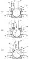
도 4는 제2실시예의 댐퍼의 구성 및 동작을 나타내는 개략도이고,4 is a schematic view showing the configuration and operation of the damper of the second embodiment;
도 5는 본 발명에 따른 도로청소차가 중앙분리대를 청소하는 경우를 나타내는 설명도이고,5 is an explanatory diagram showing a case where the road cleaning vehicle according to the present invention cleans the central separator,
도 6는 본 발명에 따른 도로청소차가 차량의 우측을 청소하는 경우를 나타내는 설명도이다.6 is an explanatory diagram showing a case where the road cleaning vehicle according to the present invention cleans the right side of the vehicle.
<도면의 주요 부분에 대한 부호의 설명><Explanation of symbols for the main parts of the drawings>
100 : 송풍기102 : 토출부100: blower 102: discharge part
104 : 흡입부110 : 호퍼104: suction unit 110: hopper
120 : 흡입마우스122 : 흡입관
130 : 청소장치120: suction mouse 122: suction tube
130: cleaning device
140, 240 : 댐퍼141, 241 : 고정부재140, 240:
142, 242 : 유입홀143, 243 : 제1유출홀142, 242:
144, 244 : 제2유출홀245 : 배기홀144, 244: second outflow hole 245: exhaust hole
146, 246 : 회전부재147 ,247 : 공기유로146, 246: rotating
148 : 개구247 : 제1개구148: opening 247: first opening
248 : 제2개구150, 250 : 배기관248:
162 : 제1호스164 : 제2호스162: hose 1 164: hose 2
300 : 중앙분리대300: center separator
본 발명은 도로청소차에 관한 것으로, 보다 상세하게는 송풍기를 구비한 일반적인 도로청소차량의 외부로 배출되는 공기를 이용하여 중앙분리대의 적재된 오물을 청소할 수 있는 도로청소차에 관한 것이다.The present invention relates to a road cleaning vehicle, and more particularly, to a road cleaning vehicle that can clean the loaded dirt of the central separator using the air discharged to the outside of the general road cleaning vehicle having a blower.
일반적인 도로청소차는 쓰레기를 진공압으로 흡입수거하기 위하여 공기를 흡입하여 토출하는 송풍기와, 송풍기의 흡입부와 연결되고 도로쓰레기가 적재되는 호퍼와, 호퍼와 흡입관에 의해 연결되고 도로쓰레기가 흡입되는 흡입마우스와, 도로쓰레기를 쓸어내어 흡입마우스로 보내는 역할을 하는 브러시와 같은 청소장치를 포함하여 구성된다. 따라서 청소장치에 의해 쓸려진 도로쓰레기는 도로면과 인접하여 설치된 흡입마우스에서 흡입되어 호퍼에 적재되고, 송풍기에서 토출되는 공기는 차량 외부로 배출된다.A general road cleaning vehicle includes a blower that sucks and discharges air to suck and collect garbage at a vacuum pressure, a hopper connected to the suction part of the blower and loaded with road garbage, and a suction that is connected by a hopper and a suction pipe and sucked with the road garbage. It comprises a mouse and a cleaning device such as a brush that serves to sweep the road debris and send it to the suction mouse. Therefore, the road garbage washed by the cleaning device is sucked by the suction mouse installed adjacent to the road surface and loaded into the hopper, and the air discharged from the blower is discharged outside the vehicle.
한편, 고속도로나 국도와 같이 차량의 통행량이 많고 고속운행되는 곳에 중앙분리대가 설치된다. 중앙분리대는 차량의 정면충돌을 방지하여 인명피해를 최소화하기 위한 교통시설이다. 일반적으로 중앙분리대는 블럭형과 철재형으로 구분할 수 있다. 블럭형 분리대는 시멘트로 이루어진 블럭형상이기 때문에, 분리대와 충돌시 충격을 흡수하지 못하여 인명피해가 크다는 단점이 있다. 따라서, 철재 기둥과 그 기둥을 연결하는 가드레일로 이루어진 연속적인 구조물로서 차량의 충돌시 철재 구조물이 휘어져 충격을 완화할 수 있는 철재 분리대가 많이 사용되고 있다. 이하, 본 발명의 중앙분리대는 철재 분리대를 의미하는 것으로 한다.On the other hand, the central divider is installed in a place where a lot of traffic and high-speed traffic, such as a highway or national road. The median divider is a traffic facility that minimizes human injury by preventing frontal collision of vehicles. In general, the median divider can be divided into block type and steel type. Since the block type separator is a block shape made of cement, it does not absorb shock when colliding with the type of separator, which has a disadvantage in that the damage to life is great. Therefore, as a continuous structure consisting of steel pillars and guardrails connecting the pillars, steel separators that can bend the steel structure when the vehicle collides to mitigate the impact are frequently used. Hereinafter, the central separator of the present invention shall mean an iron separator.
종래기술에 따른 도로청소차는 중앙분리대에 최대한 접근하여 청소를 하더라도 중앙분리대가 지나가는 도로의 중앙부분에 위치한 먼지, 모래, 쓰레기 등의 오물은 제거하지 못한다. 따라서 중앙분리대가 지나가는 도로의 중앙부분에는 오물이 계속 적재된다. 특히 동절기 제설작업시 사용된 모래가 차량에 의해 발생되는 바람에 의해 중앙분리대 주위에 다량 퇴적되는 경우가 많다. 이러한 중앙분리대 주위에 적재된 오물은 안전한 차량운행과 도로의 미관을 위하여 청소될 필요가 있는데, 인력으로 청소작업을 하는 경우 사고의 위험성이 있고 중앙분리대의 기둥 때문에 청소작업이 용이하지 않다는 문제점이 있다. 또한, 차선을 막고 작업을 하는 경우에도 교통체증이 발생하는 문제점이 있다. 따라서 중앙분리대에 적재된 오물은 대부분 방치되고 있는 실정이다.Road cleaning vehicle according to the prior art does not remove dirt, sand, rubbish, etc. located in the central portion of the road passing through the central separator even if the cleaning close to the central separator. Therefore, dirt is continuously loaded in the central part of the road where the median passes. In particular, large amounts of sand used during winter snow removal are deposited around the central separator by the wind generated by the vehicle. The dirt loaded around the median separator needs to be cleaned for safe driving and aesthetics of the road.There is a problem in that cleaning work is not easy due to the pillars of the median separator. . In addition, there is a problem that the traffic jam occurs even when working to block the lanes. Therefore, most of the dirt loaded on the median is left unattended.
본 발명은 상기와 같은 종래기술의 문제점을 해결하기 위한 것으로, 중앙분리대가 지나가는 도로의 중앙부분에 적재된 오물을 청소할 수 있는 도로청소차를 제공함에 그 목적이 있다.The present invention is to solve the problems of the prior art as described above, it is an object of the present invention to provide a road cleaning vehicle that can clean the dirt loaded on the central portion of the road passing through the separator.
본 발명의 그 밖의 목적, 특정한 장점들 및 신규한 특징들은 첨부된 도면들과 연관된 이하의 상세한 설명과 바람직한 실시예들로부터 더욱 분명해질 것이다.Other objects, specific advantages and novel features of the invention will become more apparent from the following detailed description and preferred embodiments in conjunction with the accompanying drawings.
상기의 목적을 달성하기 위하여 본 발명에 따른 중앙분리대 청소용 도로청소차는 차량에 설치되고 흡입부와 토출부를 구비하는 송풍기와, 상기 송풍기의 흡입부와 연결되고 도로쓰레기가 적재되는 호퍼와, 상기 호퍼와 흡입관에 의해 연결되고 도로쓰레기가 흡입되는 흡입마우스와, 도로쓰레기를 상기 흡입마우스로 쓸어내는 청소장치를 구비한 도로청소차에 있어서, 일단이 상기 송풍기의 토출부와 연결되는 유입홀과, 상기 유입홀의 타단과 선택적으로 연통되는 제1유출홀 및 제2유출홀이 각각 형성된 댐퍼와, 상기 댐퍼의 유입홀과 함께 상기 송풍기의 토출부와 연결되고 상기 송풍기에서 토출되는 공기를 외부로 배출시키는 배기관과, 상기 댐퍼의 제1유출홀에 연결되어 차량의 일측으로 연장된 제1호스와, 상기 댐퍼의 제2유출홀에 연결되어 차량의 타측으로 연장된 제2호스를 더 포함하는 것을 특징으로 한 다.In order to achieve the above object, the road cleaning vehicle for cleaning the median separator according to the present invention includes a blower installed in a vehicle and having a suction part and a discharge part, a hopper connected to the suction part of the blower and loaded with road garbage, and the hopper; A road cleaning vehicle having a suction mouse connected by a suction pipe and suctioned with road debris, and a cleaning device for sweeping road debris into the suction mouse, the inlet hole having one end connected to the discharge part of the blower, A damper having a first outlet hole and a second outlet hole selectively communicating with the other end, and an exhaust pipe connected to a discharge part of the blower together with an inlet hole of the damper and discharging air discharged from the blower to the outside; A first hose connected to the first outlet hole of the damper and extending to one side of the vehicle, and a vehicle connected to the second outlet hole of the damper The one characterized in that it further comprises a second hose extending side to the other.
본 발명에 따른 중앙분리대 청소용 도로청소차에 있어서, 상기 댐퍼는, 원기둥형 중공이 형성되고, 상기 유입홀이 외부로부터 중공에 이르기까지 관통형성되고, 상기 제1유출홀 및 제2유출홀이 상기 유입홀의 양쪽에 각각 형성된 고정부재와, 원주면에 개구를 가지는 공기유로가 형성되고, 상기 고정부재의 중공에 밀착삽입되어 회전할 수 있는 원기둥형상의 회전부재로 이루어지고, 상기 회전부재의 공기유로는 상기 회전부재의 회전에 따라, 상기 유입홀과 상기 고정부재의 제1유출홀을 연통시키는 제1위치와, 상기 유입홀과 상기 고정부재의 제2유출홀을 연통시키는 제2위치 사이에서 전환작동하는 것이 바람직하다.In the road cleaning vehicle for cleaning the separator according to the present invention, the damper is formed with a cylindrical hollow, the inlet hole is formed from the outside through the hollow, the first outlet hole and the second outlet hole is the inlet A fixed member formed on each side of the hole, and an air flow passage having an opening on a circumferential surface thereof, and a cylindrical rotating member rotatably inserted into the hollow of the fixed member to rotate the air flow path of the rotating member. A switching operation between a first position in communication with the inflow hole and a first outlet hole of the fixing member and a second position in communication with the inflow hole and the second outlet hole of the fixing member, as the rotation member rotates; It is desirable to.
또한, 상기의 목적을 달성하기 위하여 본 발명에 따른 중앙분리대 청소용 도로청소차는 차량에 설치되고 흡입부와 토출부를 구비하는 송풍기와, 상기 송풍기의 흡입부와 연결되고 도로쓰레기가 적재되는 호퍼와, 상기 호퍼와 흡입관에 의해 연결되고 도로쓰레기가 흡입되는 흡입마우스와, 도로쓰레기를 상기 흡입마우스로 쓸어내는 청소장치를 구비한 도로청소차에 있어서, 일단이 상기 송풍기의 토출부와 연결되는 유입홀과, 상기 유입홀의 타단과 선택적으로 연통되는 제1유출홀과 제2유출홀과 배기홀이 각각 형성된 댐퍼와, 상기 댐퍼의 제1유출홀에 연결되어 차량의 일측으로 연장된 제1호스와, 상기 댐퍼의 제2유출홀에 연결되어 차량의 타측으로 연장된 제2호스를 더 포함하는 것을 특징으로 한다.In addition, in order to achieve the above object, the road cleaning car for cleaning the separator according to the present invention includes a blower installed in a vehicle and having a suction part and a discharge part, a hopper connected to the suction part of the blower and loaded with road garbage; A road cleaning vehicle comprising a suction mouse connected by a hopper and a suction pipe and suctioned road debris, and a cleaning device for sweeping road debris into the suction mouse, the inlet hole having one end connected to the discharge part of the blower; A damper having a first outlet hole, a second outlet hole, and an exhaust hole selectively communicating with the other end of the inlet hole, a first hose connected to the first outlet hole of the damper and extending to one side of the vehicle, and the damper of the And a second hose connected to the second outlet hole and extending to the other side of the vehicle.
본 발명에 따른 중앙분리대 청소용 도로청소차에 있어서, 상기 댐퍼는 원기둥형 중공이 형성되고, 상기 유입홀이 외부로부터 중공에 이르기까지 관통형성되 고, 상기 제1유출홀 및 제2유출홀이 상기 유입홀의 양쪽에 각각 형성되고, 상기 배기홀이 상기 중공을 중심으로 상기 유입홀과 대향하여 형성된 고정부재와, 원주면에 제1개구와 제2개구를 가지는 공기유로가 내부를 관통하여 형성된 원기둥형상의 회전부재로 이루어지고, 상기 회전부재의 회전에 따라, 상기 회전부재의 제1개구가 상기 유입홀과 연통되고 상기 제2개구가 상기 배기홀과 연통되는 제1위치와, 상기 회전부재의 제1개구가 상기 유입홀 및 상기 고정부재의 제1유출홀에 연통되고 상기 제2개구는 상기 고정부재의 내주면에 의해 폐색된 제2위치와, 상기 회전부재의 제1개구가 상기 유입홀 및 상기 고정부재의 제2유출홀에 연통되고 상기 제2개구는 상기 고정부재의 내주면에 의해 폐색된 제3위치 사이에서 전환작동하는 것이 바람직하다.In the road cleaning vehicle for cleaning the separator according to the present invention, the damper is formed with a cylindrical hollow, the inlet hole is formed from the outside to the hollow, the first outlet hole and the second outlet hole of the inlet hole A cylindrical member formed on each side and having a fixed member formed with the exhaust hole facing the inlet hole about the hollow, and an air passage having a first opening and a second opening on a circumferential surface thereof penetrating therein And a first position in which the first opening of the rotating member communicates with the inflow hole and the second opening communicates with the exhaust hole in accordance with the rotation of the rotating member, and the first opening of the rotating member. A second position in communication with the inflow hole and the first outflow hole of the fixing member, the second opening being occluded by an inner circumferential surface of the fixing member, and the first opening of the rotating member being introduced And in communication with the second outlet hole of the fixing member and the second opening it is preferably operated to switch between a third position occluded by the inner circumferential surface of the fixing member.
또한, 본 발명에 따른 중앙분리대 청소용 도로청소차는 물탱크와, 상기 물탱크와 연결되어 상기 제1호스 또는 제2호스의 말단과 인접하여 설치되는 살수관을 더 포함하는 것이 바람직하다.In addition, the road cleaning car for cleaning the separator according to the present invention preferably further includes a water tank and a watering pipe connected to the water tank and installed adjacent to the end of the first hose or the second hose.
이하에서는 첨부된 도면을 참조하여 본 발명에 따른 중앙분리대 청소용 도로청소차의 바람직한 실시예를 상세히 설명한다.Hereinafter, with reference to the accompanying drawings will be described in detail a preferred embodiment of the road cleaning vehicle for cleaning the separator according to the present invention.
[제1 실시예][First Embodiment]
도 1은 본 발명의 제1실시예에 따른 중앙분리대 청소용 도로청소차의 개략적인 구성을 나타내는 구성도이고, 도 2는 제1실시예의 댐퍼의 구성 및 동작을 나타 내는 개략도이다.1 is a block diagram showing a schematic configuration of a road cleaning vehicle for cleaning the separator according to the first embodiment of the present invention, Figure 2 is a schematic diagram showing the configuration and operation of the damper of the first embodiment.
본 실시예에 따른 중앙분리대 청소용 도로청소차는 송풍기(100)와, 호퍼(110)와, 흡입마우스(120)와, 청소장치(130)와, 댐퍼(140)와, 배기관(150)과, 제1호스(162)와, 제2호스(164)를 포함하여 이루어진다.The road cleaning car for cleaning the median separator according to the present embodiment includes a
송풍기(100)는 차량에 설치되고, 차량에 구비된 엔진(미도시)에 의해 구동되어 공기를 흡입하여 토출한다. 송풍기(100)는 공기가 토출되는 토출부(102)와 공기가 흡입되는 흡입부(104)를 포함하여 이루어진다.The
호퍼(110)는 차량에 설치되고, 내부에 쓰레기를 적재하기 위해 밀폐구조를 가진다. 도 1에 도시된 바와 같이 호퍼(110)의 상부와 송풍기(100)의 흡입부(104)는 연통되어 송풍기가 작동시 호퍼(110) 내부에는 진공압이 형성된다.The
흡입마우스(120)는 도로에 인접하게 설치되고, 흡입관(122)에 의해 호퍼(110)와 연결된다. 따라서 송풍기(100)가 작동할 때 흡입마우스(120)는 진공압이 형성되고, 흡입마우스(120)와 인접하는 노면쓰레기가 흡입마우스(120)로 흡입되어 흡입관(122)을 거쳐 호퍼(110)에 적재된다.The
청소장치(130)는 흡입마우스(120)의 전방에 위치하고, 모터(미도시)에 의하여 구동되는 원통형 브러시 또는 원판형 브러시와 같은 장치로서 도로상의 쓰레기를 모아서 흡입마우스(120)로 쓸어보내는 역할을 한다.The
댐퍼(140)는 유입홀(142)과 제1유출홀(143)과 제2유출홀(144)이 형성된 구조로서 차량에 설치된다. 댐퍼의 유입홀(142)은 그 일단이 송풍기의 토출부(102)와 연결되어 송풍기에서 토출된 공기를 댐퍼 내부로 유입시킨다. 댐퍼의 유입홀(142) 은 그 타단이 제1유출홀(143)과 제2유출홀(144) 중에서 선택된 하나와 연통될 수 있는 구조를 가진다. 이때, 댐퍼의 제1유출홀(143)과 제2유출홀(144)은 차량의 좌우측 방향으로 각각 형성되는 것이 바람직하다.The
댐퍼(140)는 도 2에 도시된 바와 같이 원기둥형 중공이 형성된 고정부재(141)와, 원주면에 개구(148)를 가진 공기유로(147)가 형성된 원기둥 형상의 회전부재(146)로 이루어지는 것이 바람직하다. 이때, 고정부재(141)의 외부로부터 중공에 이르기까지 관통하여 유입홀(142)이 형성되고, 유입홀을 중심으로 그 양쪽에 제1유출홀(143)과 제2유출홀(144)이 외부로부터 중공에 이르기까지 관통하여 형성되어 있다. 이때 제1유출홀(143), 제2유출홀(144) 각각은 차량의 좌우측 방향으로 형성되는 것이 바람직하다. 회전부재(146)에 형성된 공기유로(147)의 개구(148)는 유입홀(142)과, 제1유출홀(143)과 제2유출홀(144) 중에서 선택된 하나를 모두 포함할 수 있는 크기를 가진다. 공기유로(147)는 원활한 공기의 흐름을 위해 회전부재(146)의 내부에 적절하게 형성될 수 있으나, 도 2에 도시된 바와 같이 회전부재(146)의 내부에 형성된 중공인 것이 바람직하다.The
도 2에 도시된 바와 같이, 댐퍼(140)는 고정부재(141)에 삽입된 회전부재(146)가 회전함에 따라, 회전부재의 외주면이 제1유출홀(143)과 제2유출홀(144)을 폐쇄하는 경우(a)와, 회전부재의 공기유로(147)가 유입홀(142)과 제1유출홀(143)을 연통시키는 경우(b)와, 회전부재의 공기유로(147)가 유입홀(142)과 제2유출홀(144)을 연통시키는 경우(c)를 가진다.As shown in FIG. 2, as the
배기관(150)은 상기 설명된 댐퍼(140)의 유입홀(142)과 함께 송풍기의 토출 부(102)와 연결되고 송풍기에서 토출되는 공기를 외부로 배출시킨다. 따라서 도 2의 (a)의 경우에는 송풍기에서 토출되는 공기 전부가 배기관(150)을 통하여 외부로 배출되고, 도 2의 (b) 및 (c)의 경우에는 송풍기에서 토출되는 공기의 일부가 배기관을 통하여 외부로 배출된다.The
제1호스(162) 및 제2호스(164)는 댐퍼(140)의 제1유출홀(143), 제2유출홀(144)에 각각 연결된다. 제1호스 및 제2호스는 도 5 및 도 6에 도시된 바와 같이 신축가능하고, 제1, 제2호스를 이용하여 차량의 좌우측을 청소하는 경우 호스를 신장시켜 그 말단이 차량의 좌우측 하단부에 고정되는 것이 바람직하다. 또한 제1, 제2호스를 사용하지 않을 경우에는 호스를 단축시켜 그 말단을 차량에 고정시키는 구조를 갖는 것이 바람직하다.The
또한, 차량에 설치되는 물탱크(미도시)와, 물탱크와 연결되어 제1호스(162) 또는 제2호스(164)의 말단과 인접하여 설치되는 살수관(미도시)을 더 포함하는 것이 바람직하다. 살수관의 말단에는 노즐(미도시)이 장착되어 제1 및 제2호스(162,164)를 사용하여 도로청소차의 좌우측을 청소하는 경우 물을 분사하여 먼지발생을 억제시킨다.In addition, further comprising a water tank (not shown) installed in the vehicle, and a watering pipe (not shown) connected to the water tank and installed adjacent to the end of the
이하에서는 상기 구성을 가진 제1실시예에 대한 작동을 설명한다.The operation of the first embodiment having the above configuration will be described below.
도로청소차가 일반적인 도로청소를 실시하는 경우에는 도 2의 (a)에 도시된 바와 같이 댐퍼(140)의 회전부재(146)의 외주면이 고정부재(141)의 제1유출홀(143) 및 제2유출홀(144)을 폐쇄시키도록 하여, 송풍기의 토출부(102)에서 토출된 공기가 댐퍼(140)로 흐르는 것이 차단되어 배기관(150)을 통하여서만 차량 외부로 배출된 다. 이때, 도 1에 도시된 바와 같이 청소장치(130)와 송풍기(100)를 가동하여 도로상의 쓰레기를 쓸어서 흡입마우스(120)를 통하여 호퍼(110)로 흡입한다. 도 1의 화살표는 송풍기(100)에 의한 공기의 흐름을 나타낸다.When the road cleaning vehicle performs general road cleaning, the outer circumferential surface of the rotating
도로청소차가 중앙분리대에 적재된 오물을 청소하는 경우에는 도 2의 (b)에 도시된 바와 같이, 댐퍼(140)의 회전부재(146)를 도 2의 (a)의 위치에서 반시계방향으로 회전시켜 고정부재의 유입홀(142)과 제1유출홀(143)을 연통시킨다. 따라서 송풍기의 토출부(102)에서 토출된 공기는 배기관(150)으로 일부가 배출되고 나머지는 고정부재의 유입홀(142)과 회전부재의 공기유로(147)와 고정부재의 제1유출홀(143)을 거쳐 제1호스를 통하여 외부로 배출된다. 도 5를 참고하면 제1호스(162)의 말단은 차량 좌측 하단부에 고정되고, 제1호스(162)를 통하여 외부로 배출되는 공기는 중앙분리대(300)의 적재오물(310)을 반대편 도로측으로 불어내게 된다. 이때, 호스 말단의 형상을 적절히 하거나, 송풍기(100)의 출력을 높힘으로서 보다 강력한 바람으로 적재오물을 불어내는 것이 가능하다. 또한, 제1호스(162)와 인접하여 설치된 살수관(미도시)의 말단에 장착된 노즐을 통하여 물이 분사되어 중앙분리대를 청소하면서 먼지의 발생을 막을 수 있다. 이후에 도로청소차는 중앙분리대 반대편 도로에서 오물을 흡입함으로서 청소가 완료된다.When the road cleaning vehicle cleans the dirt loaded on the central separator, as shown in FIG. 2B, the
도로청소차가 노견부에 널려진 풀이나 낙엽 등을 청소하는 경우에는 도 2의 (c)에 도시된 바와 같이, 댐퍼(140)의 회전부재를 도 3의 (a)의 위치에서 시계방향으로 회전시켜 고정부재의 유입홀(142)과 제2유출홀(143)을 연통시킨다. 따라서 송풍기의 토출부(102)에서 토출된 공기는 배기관(150)으로 일부가 배출되고 나머지는 고정부재의 유입홀(142)과 회전부재의 공기유로(147)와 고정부재의 제2유출홀(144)을 거쳐 제2호스를 통하여 외부로 배출된다. 도 6을 참고하면 제2호스(164)의 말단은 차량 우측 하단부에 고정되고, 제2호스(164)를 통하여 외부로 배출된 공기는 노견부에 널려진 제초된 풀이나 낙엽, 그 밖에 이물질들을 도로 바깥쪽으로 불어낸다. 이때 제2호스(164)와 인접하여 설치된 살수관(미도시)의 말단에 장착된 노즐을 통하여 물이 분사되어 먼지의 발생을 막을 수 있다.When the road cleaning vehicle cleans grass or fallen leaves that are hanging on the roadside part, as shown in FIG. 2C, the rotary member of the
[제2실시예]Second Embodiment
도 3은 본 발명의 제2실시예에 따른 중앙분리대 청소용 도로청소차의 개략적인 구성을 나타내는 구성도이고, 도 4는 제2실시예의 댐퍼의 구성 및 동작을 나타내는 개략도이다.3 is a configuration diagram showing a schematic configuration of a road cleaning vehicle for cleaning a median separator according to a second embodiment of the present invention, Figure 4 is a schematic diagram showing the configuration and operation of the damper of the second embodiment.
본 실시예에 따른 중앙분리대 청소용 도로청소차는 송풍기(100)와, 호퍼(110)와, 흡입마우스(120)와, 청소장치(130)와, 댐퍼(240)와, 배기관(250)과, 제1호스(162)와, 제2호스(164)를 포함하여 이루어진다.The road cleaning vehicle for cleaning the median separator according to the present embodiment includes a
본 실시예의 설명에 있어서 앞선 실시예와 동일한 구성에 대해서는 동일한 도면부호를 부여하며, 중복설명을 피하기 위해 설명을 생략한다.In the description of the present embodiment, the same reference numerals are given to the same components as in the previous embodiment, and the description is omitted in order to avoid redundant description.
댐퍼(240)는 유입홀(242)과 제1유출홀(243)과 제2유출홀(244)과 배기홀(245)이 형성된 구조로서 차량에 설치된다. 댐퍼의 유입홀(242)은 그 일단이 송풍기의 토출부(102)와 연결되어 송풍기에서 토출된 공기를 댐퍼 내부로 유입시킨다. 댐퍼의 유입홀(242)은 그 타단이 제1유출홀(243)과 제2유출홀(244)과 배기홀(245) 중에 서 선택된 하나와 연통하는 구조를 가진다.The
댐퍼(240)는 도 4에 도시한 바와 같이 원기둥형 중공이 형성된 고정부재(241)와, 원주면에 제1개구(248)와 제2개구(249)를 가지는 공기유로(247)가 내부에 형성된 원기둥 형상의 회전부재(246)로 이루어지는 것이 바람직하다. 이때, 고정부재(241)의 외부로부터 중공에 이르기까지 관통하여 유입홀(242)이 형성되고, 유입홀을 중심으로 그 양쪽에 제1유출홀(243)과 제2유출홀(244)이 외부로부터 중공에 이르기까지 관통하여 형성되고, 중공을 중심으로 유입홀(242)와 대향하여 배기홀(245)이 외부로부터 중공에 이르기까지 관통하여 형성된다. 이때, 회전부재(246)에 형성된 공기유로(247)의 제1개구(248)는 유입홀(242)과, 제1유출홀(243)과 제2유출홀(244) 중에서 선택된 하나를 모두 포함할 수 있는 크기를 가진다. 또한, 공기유로(247)의 제2개구(249)는 고정부재의 배기홀(245)과 연통될 수 있는 크기, 바람직하게는 배기홀(245)과 실질적으로 동일한 크기를 가진다. 회전부재의 공기유로(247)는 원활한 공기의 흐름을 위해 회전부재(246)의 내부에 적절하게 형성될 수 있으나, 도 4에 도시된 바와 같이 회전부재(246)의 내부에 형성된 중공인 것이 바람직하다.As shown in FIG. 4, the
도 4에 도시된 바와 같이, 댐퍼(240)는 고정부재(241)에 삽입된 회전부재(246)가 회전함에 따라 다음과 같은 경우를 갖는다. 도 4의 (a)는 회전부재의 외주면이 제1유출홀(243)과 제2유출홀(244)을 폐쇄하고 고정부재의 유입홀(242) 및 배기홀(245)이 각각 회전부재의 제1개구(248) 및 제2개구(249)와 연통되는 경우이다. 도 4의 (b)는 회전부재의 공기유로(247)가 유입홀(242)과 제1유출홀(243)을 연 통시키고 회전부재의 외주면이 고정부재의 배기홀(245)을 폐쇄하는 경우이다. 도 4의 (c)는 회전부재의 공기유로(247)가 유입홀(242)과 제2유출홀(244)을 연통시키고 회전부재의 외주면이 고정부재의 배기홀(245)을 폐쇄하는 경우이다.As shown in FIG. 4, the
배기관(250)은 고정부재(241)의 배기홀(245)와 연결되어 송풍기에서 토출되는 공기가 외부로 배출되는 통로가 된다. 배기관(250) 없이 고정부재의 배기홀(245)을 통해서 외부로 배출되는 것도 가능하다. 도 4의 (a)를 참고하면 배기관(250)을 통해서만 송풍기에서 토출된 공기가 외부로 배출된다. 그러나 도 4의 (b) 및 도 4의 (c)의 경우에는 회전부재의 외주면에 의해 배기홀(245)이 폐쇄되어 배기관(250)을 통하여 공기가 배출되지 않는다. 즉, 도 4의 (b)의 경우에는 송풍기에서 토출된 공기는 제1유출홀(243)과 제1호스(162)를 거쳐 외부로 배출되고, 도 2의 (c)의 경우에는 송풍기에서 토출된 공기는 제2유출홀(244)와 제2호스(164)를 거쳐 외부로 배출된다.The
이하에서는 상기 구성을 가진 제2실시예의 작동을 설명한다.The following describes the operation of the second embodiment having the above configuration.
도로청소차가 일반적인 도로청소를 실시하는 경우에는 도 4의 (a)에 도시된 바와 같이 댐퍼(240)의 회전부재(246)의 외주면이 고정부재(241)의 제1유출홀(243) 및 제2유출홀(244)을 폐쇄하므로, 송풍기의 토출부(102)에서 토출된 공기는 댐퍼의 유입홀(242)과 제1개구(248)와 제2개구(249)와 배기홀(245)을 통하여서만 차량 외부로 배출된다. 도 3의 화살표는 이러한 경우에 송풍기(100)에 의한 공기의 흐름을 나타낸다.When the road cleaning vehicle performs general road cleaning, the outer circumferential surface of the rotating
도로청소차가 중앙분리대에 적재된 오물을 청소하는 경우에는 도 4의 (b)에 도시된 바와 같이, 댐퍼(240)의 회전부재(246)를 도 4의 (a)의 위치에서 반시계방향으로 회전시켜 고정부재의 유입홀(242)과 제1유출홀(243)을 연통시키고, 회전부재(246)의 외주면은 배기홀(245)을 폐쇄시킨다. 따라서 송풍기의 토출부(102)에서 토출된 공기는 고정부재의 유입홀(242)과 회전부재의 공기유로(247)와 고정부재의 제1유출홀(243)을 거쳐 제1호스(162)를 통하여 외부로 배출된다. 도 5를 참고하면 제1호스(162)의 말단은 차량 좌측 하단부에 고정되고, 제1호스(162)를 통하여 외부로 배출된 공기는 중앙분리대(300)의 적재오물(310)을 반대편 도로측으로 불어내게 된다. 이때, 호스 말단의 형상을 적절히 하거나, 송풍기(100)의 출력을 높힘으로서 보다 강력한 바람으로 적재오물을 불어내는 것이 가능하다. 또한, 제1호스(162)와 인접하여 설치된 살수관(미도시)의 말단에 장착된 노즐을 통하여 물이 분사되어 중앙분리대를 청소하면서 먼지의 발생을 막을 수 있다. 이후에 도로청소차는 중앙분리대 반대편 도로에서 오물을 흡입함으로서 청소가 완료된다.When the road cleaning vehicle cleans the dirt loaded on the central separator, as shown in FIG. 4B, the
도로청소차가 노견부에 널려진 풀이나 낙엽 등을 청소하는 경우에는 도 4의 (c)에 도시된 바와 같이, 댐퍼(140)의 회전부재를 도 4의 (a)의 위치에서 시계방향으로 회전시켜 고정부재의 유입홀(242)과 제2유출홀(243)을 연통시키고, 회전부재(246)의 외주면은 배기홀(245)을 폐쇄시킨다. 따라서 송풍기의 토출부(102)에서 토출된 공기는 고정부재의 유입홀(242)과 회전부재의 공기유로(247)와 고정부재의 제2유출홀(244)을 거쳐 제2호스(164)를 통하여 외부로 배출된다. 도 6을 참고하면 제2호스(164)의 말단은 차량 우측 하단부에 고정되고, 제2호스(164)를 통하여 외부로 배출된 공기는 노견부에 널려진 제초된 풀이나 낙엽, 그 밖에 이물질들을 도로 바깥쪽으로 불어낸다. 이때 제2호스(164)와 인접하여 설치된 살수관(미도시)의 말단에 장착된 노즐을 통하여 물이 분사되어 먼지의 발생을 막을 수 있다.When the road cleaning car cleans grass or fallen leaves that are hanging on the roadside part, as shown in FIG. 4C, the rotary member of the
이상에서 설명한 바와 같이 본 발명에 따른 중앙분리대 청소용 도로청소차에 의하면, 댐퍼를 구비하여 차량 외부로 배출되는 공기를 이용함으로서 중앙분리대에 적재된 오물을 간편하게 청소할 수 있다. 또한, 제초작업 후에 노견부에 널려진 풀이나 낙엽 등을 청소할 수 있다.As described above, according to the road cleaning vehicle for cleaning the median separator according to the present invention, by using the air discharged to the outside of the vehicle with a damper, dirt loaded on the median separator can be easily cleaned. In addition, after weeding, grass, fallen leaves, etc., which have spread on the shoulder part can be cleaned.
Claims (5)
Translated fromKoreanPriority Applications (1)
| Application Number | Priority Date | Filing Date | Title |
|---|---|---|---|
| KR1020070036161AKR100855188B1 (en) | 2007-04-12 | 2007-04-12 | Roadway Cleaning Car |
Applications Claiming Priority (1)
| Application Number | Priority Date | Filing Date | Title |
|---|---|---|---|
| KR1020070036161AKR100855188B1 (en) | 2007-04-12 | 2007-04-12 | Roadway Cleaning Car |
Publications (1)
| Publication Number | Publication Date |
|---|---|
| KR100855188B1true KR100855188B1 (en) | 2008-09-01 |
Family
ID=40022068
Family Applications (1)
| Application Number | Title | Priority Date | Filing Date |
|---|---|---|---|
| KR1020070036161AExpired - Fee RelatedKR100855188B1 (en) | 2007-04-12 | 2007-04-12 | Roadway Cleaning Car |
Country Status (1)
| Country | Link |
|---|---|
| KR (1) | KR100855188B1 (en) |
Cited By (6)
| Publication number | Priority date | Publication date | Assignee | Title |
|---|---|---|---|---|
| KR101103139B1 (en) | 2009-01-23 | 2012-01-04 | 한국도로공사 | Road cleaning vehicles that can be cleaned using a central separator |
| KR101523201B1 (en)* | 2014-10-27 | 2015-05-29 | 주식회사 광림 | Air re-circulation road sweeping vehicle |
| CN107806048A (en)* | 2017-10-20 | 2018-03-16 | 长沙中联重科环境产业有限公司 | Sweeper |
| KR101958423B1 (en)* | 2018-09-13 | 2019-03-14 | 신정개발특장차 주식회사 | Road sweeper |
| KR101967740B1 (en)* | 2018-12-14 | 2019-04-10 | 신정개발특장차 주식회사 | Air regenerative road sweeper |
| CN111593694A (en)* | 2020-06-08 | 2020-08-28 | 烟台海德专用汽车有限公司 | A kind of double fan rapid operation road sweeper and road sweeping method |
Citations (4)
| Publication number | Priority date | Publication date | Assignee | Title |
|---|---|---|---|---|
| US4006511A (en) | 1976-01-08 | 1977-02-08 | Fmc Corporation | Sweeper with recirculation hood and independent filter system |
| JPH0220712A (en)* | 1988-07-08 | 1990-01-24 | Hokkaido Kaihatsukiyoku Kensetsu Kikai Kousakushiyochiyou | Water economization type air circulation type road sweeper |
| JPH0827752A (en)* | 1994-07-12 | 1996-01-30 | N L Kiko:Kk | Cleaning of guide rail and its cleaning truck |
| JP2004324152A (en) | 2003-04-23 | 2004-11-18 | Howa Mach Ltd | Road sweeper |
- 2007
- 2007-04-12KRKR1020070036161Apatent/KR100855188B1/ennot_activeExpired - Fee Related
Patent Citations (4)
| Publication number | Priority date | Publication date | Assignee | Title |
|---|---|---|---|---|
| US4006511A (en) | 1976-01-08 | 1977-02-08 | Fmc Corporation | Sweeper with recirculation hood and independent filter system |
| JPH0220712A (en)* | 1988-07-08 | 1990-01-24 | Hokkaido Kaihatsukiyoku Kensetsu Kikai Kousakushiyochiyou | Water economization type air circulation type road sweeper |
| JPH0827752A (en)* | 1994-07-12 | 1996-01-30 | N L Kiko:Kk | Cleaning of guide rail and its cleaning truck |
| JP2004324152A (en) | 2003-04-23 | 2004-11-18 | Howa Mach Ltd | Road sweeper |
Cited By (6)
| Publication number | Priority date | Publication date | Assignee | Title |
|---|---|---|---|---|
| KR101103139B1 (en) | 2009-01-23 | 2012-01-04 | 한국도로공사 | Road cleaning vehicles that can be cleaned using a central separator |
| KR101523201B1 (en)* | 2014-10-27 | 2015-05-29 | 주식회사 광림 | Air re-circulation road sweeping vehicle |
| CN107806048A (en)* | 2017-10-20 | 2018-03-16 | 长沙中联重科环境产业有限公司 | Sweeper |
| KR101958423B1 (en)* | 2018-09-13 | 2019-03-14 | 신정개발특장차 주식회사 | Road sweeper |
| KR101967740B1 (en)* | 2018-12-14 | 2019-04-10 | 신정개발특장차 주식회사 | Air regenerative road sweeper |
| CN111593694A (en)* | 2020-06-08 | 2020-08-28 | 烟台海德专用汽车有限公司 | A kind of double fan rapid operation road sweeper and road sweeping method |
Similar Documents
| Publication | Publication Date | Title |
|---|---|---|
| KR100855188B1 (en) | Roadway Cleaning Car | |
| CN100529268C (en) | Multifunctional complete sucking type sweeping car | |
| KR100926900B1 (en) | Road dust sweeper with four seasons | |
| CN201165647Y (en) | Multifunctional cleaning road sweeper | |
| CN101387104B (en) | Road sweeper and sweeping method thereof | |
| KR101214623B1 (en) | Road sweeper | |
| CN109083070B (en) | Brushless disc high-pressure gas sweeper | |
| KR102000240B1 (en) | Road sweeper with atmospheric purification apparatus | |
| CN110512557A (en) | The high-pressure washing of sweeper sweeps method and sweeps vehicle without brush high-pressure washing | |
| CN108396695A (en) | A kind of road cleaner | |
| KR200243344Y1 (en) | Subway track traveling gutter dreding car | |
| KR100977510B1 (en) | Street cleaning vehicle with bag filter | |
| CN206591476U (en) | A kind of high-pressure jet cleaning device and roadway pollution remove car | |
| CN108505481A (en) | A kind of sweeper sucker with rubbish drainage device | |
| CN108385571A (en) | A kind of sweeper side-spraying device | |
| CN110747793A (en) | Road cleaning device | |
| CN110184985A (en) | Special washing and sweeping fan for washing and sweeping vehicle | |
| CN206680933U (en) | A kind of air stream drives for road sweeper pick up dirt device | |
| CN100417769C (en) | Suction nozzles with combined blowback for road sweeping | |
| CN110541379A (en) | Motor sweeper with purging function | |
| US6735814B2 (en) | Apparatus for cleaning hard-to-reach areas | |
| CN218842984U (en) | Blowing-sucking type dust suction device | |
| KR200169752Y1 (en) | Cyclon type street sweeping truck | |
| CN214363213U (en) | A high-pressure cleaning auxiliary side suction device for a sweeper | |
| KR101042566B1 (en) | Road dust suction car with bag filter device |
Legal Events
| Date | Code | Title | Description |
|---|---|---|---|
| A201 | Request for examination | ||
| PA0109 | Patent application | St.27 status event code:A-0-1-A10-A12-nap-PA0109 | |
| PA0201 | Request for examination | St.27 status event code:A-1-2-D10-D11-exm-PA0201 | |
| D13-X000 | Search requested | St.27 status event code:A-1-2-D10-D13-srh-X000 | |
| D14-X000 | Search report completed | St.27 status event code:A-1-2-D10-D14-srh-X000 | |
| E902 | Notification of reason for refusal | ||
| PE0902 | Notice of grounds for rejection | St.27 status event code:A-1-2-D10-D21-exm-PE0902 | |
| P11-X000 | Amendment of application requested | St.27 status event code:A-2-2-P10-P11-nap-X000 | |
| P13-X000 | Application amended | St.27 status event code:A-2-2-P10-P13-nap-X000 | |
| P11-X000 | Amendment of application requested | St.27 status event code:A-2-2-P10-P11-nap-X000 | |
| P13-X000 | Application amended | St.27 status event code:A-2-2-P10-P13-nap-X000 | |
| E701 | Decision to grant or registration of patent right | ||
| PE0701 | Decision of registration | St.27 status event code:A-1-2-D10-D22-exm-PE0701 | |
| GRNT | Written decision to grant | ||
| PR0701 | Registration of establishment | St.27 status event code:A-2-4-F10-F11-exm-PR0701 | |
| PR1002 | Payment of registration fee | St.27 status event code:A-2-2-U10-U11-oth-PR1002 Fee payment year number:1 | |
| PG1601 | Publication of registration | St.27 status event code:A-4-4-Q10-Q13-nap-PG1601 | |
| PN2301 | Change of applicant | St.27 status event code:A-5-5-R10-R13-asn-PN2301 St.27 status event code:A-5-5-R10-R11-asn-PN2301 | |
| PR1001 | Payment of annual fee | St.27 status event code:A-4-4-U10-U11-oth-PR1001 Fee payment year number:4 | |
| FPAY | Annual fee payment | Payment date:20120821 Year of fee payment:5 | |
| PR1001 | Payment of annual fee | St.27 status event code:A-4-4-U10-U11-oth-PR1001 Fee payment year number:5 | |
| FPAY | Annual fee payment | Payment date:20130730 Year of fee payment:6 | |
| PR1001 | Payment of annual fee | St.27 status event code:A-4-4-U10-U11-oth-PR1001 Fee payment year number:6 | |
| FPAY | Annual fee payment | Payment date:20140728 Year of fee payment:7 | |
| PR1001 | Payment of annual fee | St.27 status event code:A-4-4-U10-U11-oth-PR1001 Fee payment year number:7 | |
| R17-X000 | Change to representative recorded | St.27 status event code:A-5-5-R10-R17-oth-X000 | |
| FPAY | Annual fee payment | Payment date:20150824 Year of fee payment:8 | |
| PR1001 | Payment of annual fee | St.27 status event code:A-4-4-U10-U11-oth-PR1001 Fee payment year number:8 | |
| FPAY | Annual fee payment | Payment date:20160825 Year of fee payment:9 | |
| PR1001 | Payment of annual fee | St.27 status event code:A-4-4-U10-U11-oth-PR1001 Fee payment year number:9 | |
| P22-X000 | Classification modified | St.27 status event code:A-4-4-P10-P22-nap-X000 | |
| LAPS | Lapse due to unpaid annual fee | ||
| PC1903 | Unpaid annual fee | St.27 status event code:A-4-4-U10-U13-oth-PC1903 Not in force date:20170826 Payment event data comment text:Termination Category : DEFAULT_OF_REGISTRATION_FEE | |
| P22-X000 | Classification modified | St.27 status event code:A-4-4-P10-P22-nap-X000 | |
| PC1903 | Unpaid annual fee | St.27 status event code:N-4-6-H10-H13-oth-PC1903 Ip right cessation event data comment text:Termination Category : DEFAULT_OF_REGISTRATION_FEE Not in force date:20170826 | |
| R18-X000 | Changes to party contact information recorded | St.27 status event code:A-5-5-R10-R18-oth-X000 |