KR100854795B1 - Device for speed ratio adjustment of roller traction transmission and continuous variable transmission - Google Patents
Device for speed ratio adjustment of roller traction transmission and continuous variable transmissionDownload PDFInfo
- Publication number
- KR100854795B1 KR100854795B1KR1020077019876AKR20077019876AKR100854795B1KR 100854795 B1KR100854795 B1KR 100854795B1KR 1020077019876 AKR1020077019876 AKR 1020077019876AKR 20077019876 AKR20077019876 AKR 20077019876AKR 100854795 B1KR100854795 B1KR 100854795B1
- Authority
- KR
- South Korea
- Prior art keywords
- transmission
- spindle
- platform
- support member
- support
- Prior art date
- Legal status (The legal status is an assumption and is not a legal conclusion. Google has not performed a legal analysis and makes no representation as to the accuracy of the status listed.)
- Expired - Fee Related
Links
Images


Classifications
- F—MECHANICAL ENGINEERING; LIGHTING; HEATING; WEAPONS; BLASTING
- F16—ENGINEERING ELEMENTS AND UNITS; GENERAL MEASURES FOR PRODUCING AND MAINTAINING EFFECTIVE FUNCTIONING OF MACHINES OR INSTALLATIONS; THERMAL INSULATION IN GENERAL
- F16H—GEARING
- F16H15/00—Gearings for conveying rotary motion with variable gear ratio, or for reversing rotary motion, by friction between rotary members
- F16H15/02—Gearings for conveying rotary motion with variable gear ratio, or for reversing rotary motion, by friction between rotary members without members having orbital motion
- F16H15/04—Gearings providing a continuous range of gear ratios
- F—MECHANICAL ENGINEERING; LIGHTING; HEATING; WEAPONS; BLASTING
- F16—ENGINEERING ELEMENTS AND UNITS; GENERAL MEASURES FOR PRODUCING AND MAINTAINING EFFECTIVE FUNCTIONING OF MACHINES OR INSTALLATIONS; THERMAL INSULATION IN GENERAL
- F16H—GEARING
- F16H15/00—Gearings for conveying rotary motion with variable gear ratio, or for reversing rotary motion, by friction between rotary members
- F16H15/48—Gearings for conveying rotary motion with variable gear ratio, or for reversing rotary motion, by friction between rotary members with members having orbital motion
- F16H15/50—Gearings providing a continuous range of gear ratios
- F16H15/52—Gearings providing a continuous range of gear ratios in which a member of uniform effective diameter mounted on a shaft may co-operate with different parts of another member
- B—PERFORMING OPERATIONS; TRANSPORTING
- B62—LAND VEHICLES FOR TRAVELLING OTHERWISE THAN ON RAILS
- B62M—RIDER PROPULSION OF WHEELED VEHICLES OR SLEDGES; POWERED PROPULSION OF SLEDGES OR SINGLE-TRACK CYCLES; TRANSMISSIONS SPECIALLY ADAPTED FOR SUCH VEHICLES
- B62M11/00—Transmissions characterised by the use of interengaging toothed wheels or frictionally-engaging wheels
- B62M11/04—Transmissions characterised by the use of interengaging toothed wheels or frictionally-engaging wheels of changeable ratio
- B62M11/12—Transmissions characterised by the use of interengaging toothed wheels or frictionally-engaging wheels of changeable ratio with frictionally-engaging wheels
- F—MECHANICAL ENGINEERING; LIGHTING; HEATING; WEAPONS; BLASTING
- F16—ENGINEERING ELEMENTS AND UNITS; GENERAL MEASURES FOR PRODUCING AND MAINTAINING EFFECTIVE FUNCTIONING OF MACHINES OR INSTALLATIONS; THERMAL INSULATION IN GENERAL
- F16H—GEARING
- F16H15/00—Gearings for conveying rotary motion with variable gear ratio, or for reversing rotary motion, by friction between rotary members
- F16H15/02—Gearings for conveying rotary motion with variable gear ratio, or for reversing rotary motion, by friction between rotary members without members having orbital motion
- F16H15/04—Gearings providing a continuous range of gear ratios
- F16H15/06—Gearings providing a continuous range of gear ratios in which a member A of uniform effective diameter mounted on a shaft may co-operate with different parts of a member B
- F16H15/26—Gearings providing a continuous range of gear ratios in which a member A of uniform effective diameter mounted on a shaft may co-operate with different parts of a member B in which the member B has a spherical friction surface centered on its axis of revolution
- F16H15/28—Gearings providing a continuous range of gear ratios in which a member A of uniform effective diameter mounted on a shaft may co-operate with different parts of a member B in which the member B has a spherical friction surface centered on its axis of revolution with external friction surface
- F—MECHANICAL ENGINEERING; LIGHTING; HEATING; WEAPONS; BLASTING
- F16—ENGINEERING ELEMENTS AND UNITS; GENERAL MEASURES FOR PRODUCING AND MAINTAINING EFFECTIVE FUNCTIONING OF MACHINES OR INSTALLATIONS; THERMAL INSULATION IN GENERAL
- F16H—GEARING
- F16H61/00—Control functions within control units of change-speed- or reversing-gearings for conveying rotary motion ; Control of exclusively fluid gearing, friction gearing, gearings with endless flexible members or other particular types of gearing
- F16H61/66—Control functions within control units of change-speed- or reversing-gearings for conveying rotary motion ; Control of exclusively fluid gearing, friction gearing, gearings with endless flexible members or other particular types of gearing specially adapted for continuously variable gearings
- F16H61/664—Friction gearings
- F16H61/6649—Friction gearings characterised by the means for controlling the torque transmitting capability of the gearing
- F—MECHANICAL ENGINEERING; LIGHTING; HEATING; WEAPONS; BLASTING
- F16—ENGINEERING ELEMENTS AND UNITS; GENERAL MEASURES FOR PRODUCING AND MAINTAINING EFFECTIVE FUNCTIONING OF MACHINES OR INSTALLATIONS; THERMAL INSULATION IN GENERAL
- F16H—GEARING
- F16H63/00—Control outputs from the control unit to change-speed- or reversing-gearings for conveying rotary motion or to other devices than the final output mechanism
- F16H63/02—Final output mechanisms therefor; Actuating means for the final output mechanisms
- F16H63/04—Final output mechanisms therefor; Actuating means for the final output mechanisms a single final output mechanism being moved by a single final actuating mechanism
- F16H63/06—Final output mechanisms therefor; Actuating means for the final output mechanisms a single final output mechanism being moved by a single final actuating mechanism the final output mechanism having an indefinite number of positions
- F16H63/067—Final output mechanisms therefor; Actuating means for the final output mechanisms a single final output mechanism being moved by a single final actuating mechanism the final output mechanism having an indefinite number of positions mechanical actuating means
Landscapes
- Engineering & Computer Science (AREA)
- General Engineering & Computer Science (AREA)
- Mechanical Engineering (AREA)
- Chemical & Material Sciences (AREA)
- Combustion & Propulsion (AREA)
- Transportation (AREA)
- Friction Gearing (AREA)
- General Details Of Gearings (AREA)
- Valve Device For Special Equipments (AREA)
- Valve-Gear Or Valve Arrangements (AREA)
- Electrical Discharge Machining, Electrochemical Machining, And Combined Machining (AREA)
- Retarders (AREA)
Abstract
Translated fromKorean
Description
Translated fromKorean본 발명의 분야는 일반적으로 변속기에 관한 것으로, 더 상세하게는 본 발명은 연속 가변 변속기에 관한 것이다.FIELD OF THE INVENTION The field of the present invention generally relates to transmissions, and more particularly the present invention relates to continuous variable transmissions.
본 발명은 연속 가변 변속기 분야에 관한 것이며, 종래의 기술에 대하여 개량과 개발해 온 몇 가지 새로운 특징과 발명적인 측면을 포함한다. 무한 가변 변속기를 제공하기 위해서, 다양한 트랙션 롤러 변속기-동력이 하우징 내에서 토크 입력 디스크와 출력 디스크 사이에서 지지되는 트랙션 롤러를 통하여 전달되는-가 개발되었다. 이러한 변속기에서는 트랙션 롤러가 지지 구조물에 장착되는데, 그 구조물은, 피봇될 때, 트랙션 롤러를 토크 디스크와 원하는 변속비에 따른 직경으로 변화하는 원들 내에서 맞물리게 한다.The present invention relates to the field of continuous variable transmissions and includes several new features and inventive aspects that have been improved and developed over the prior art. In order to provide an infinitely variable transmission, various traction roller transmissions have been developed in which power is transmitted through a traction roller supported between a torque input disk and an output disk in a housing. In such transmissions, a traction roller is mounted to the support structure, which, when pivoted, engages the traction roller with the torque disk in circles that vary in diameter according to the desired transmission ratio.
그러나 이러한 전통적인 해결책이 이룬 성공은 제한적이었다. 예를 들면, 어느 하나의 해결책은 가변 조정 변속비를 갖는 차량의 구동 허브를 개시하고 있다. 이 방법이 알려 주는 것은 각각의 롤러의 회전 축선을 틸팅하는, 트랙션 롤러의 각 각의 측면에 하나씩, 두개의 아이리스 플레이트를 사용하는 것이다. 그러나 아이리스 플레이트를 사용하면 매우 복잡해질 수 있는데, 이는 변속 변환 중에 아이리스 플레이트를 조절하기 위해 요구되는 많은 수의 부품들 때문이다. 이 변속기의 다른 어려움은 각각의 롤러에 대하여 주로 정지상태이도록 구성된 가이드링을 갖는다는 점이다. 이 가이드링은 정지 상태이므로, 각 트랙션 롤러의 회전축선을 변환하는 것이 어렵다.However, the success of these traditional solutions has been limited. For example, one solution discloses a drive hub of a vehicle having a variable speed ratio. What this method teaches is to use two iris plates, one on each side of the traction roller, which tilts the axis of rotation of each roller. However, using an iris plate can be very complicated because of the large number of components required to adjust the iris plate during shifting conversion. Another difficulty with this transmission is that it has a guide ring configured for each roller mainly to be stationary. Since this guide ring is stationary, it is difficult to change the rotational axis of each traction roller.
위와 같은 이전의 디자인에 대한 하나의 개선된 것은 구동 부재와 피구동부재가 그를 중심으로 회전하는 축을 구비한다. 구동부재와 피구동부재는 모두 축에 설치되고 등거리로 축에 대하여 반경방향으로 배치된 다수의 동력 조절기와 접촉한다. 동력 조절기는 두 부재 모두와 마찰접촉하고, 구동부재로부터 피구동부재로 동력을 전달한다. 축의 동심원 상에 그리고 동력 조절기들 사이에 위치하는 지지부재는 구동부재와 피구동부재에 대한 마찰접촉을 만들기 위하여 동력 조절기들을 분리시키는 힘을 가한다. 이러한 설계의 한계는 변속기의 토크하중이 변함에 따라 구동부재와 피구동부재가 동력 조절기에 대한 충분한 마찰접촉 상태를 유지하도록 하는 충분한 축방향 힘을 만들기 위한 수단이 없다는 것이다. 이러한 설계의 더욱 더 큰 한계는 타력운전(coasting; 이하 관성운전 또는 타성운전이라고도 함)시 변속기의 연결을 풀기 위한 수단이 충분하지 못할 뿐만 아니라 높은 토크와 매우 낮은 속력 상태로 변환하는 것이 어렵다는 것이다.One improvement to the previous design as above includes an axis in which the drive member and driven member rotate about it. The drive member and the driven member are both mounted on the shaft and in contact with a plurality of power regulators arranged radially with respect to the shaft at equidistant distances. The power regulator is in frictional contact with both members and transmits power from the drive member to the driven member. The support member located on the concentric circle of the shaft and between the power regulators exerts a force that separates the power regulators to make frictional contact with the drive member and the driven member. The limitation of this design is that there is no means for producing sufficient axial force to keep the drive and driven members in sufficient frictional contact with the power regulator as the torque load of the transmission changes. A further limitation of this design is that not only is there insufficient means to disengage the transmission during coasting (also referred to as inertia or inertia), but it is also difficult to convert to high torque and very low speed states.
그러므로 개선된 동력 조절기 지지체 및 변환 기구와, 가변 토크와 동력 부하에 대하여 적절한 축방향 추력을 구동부재와 피구동부재에 가하기 위한 수단과, 타력운전을 위해 클러치의 연결을 풀고 다시 연결하는 수단을 갖는 연속 가변 변속기가 필요하다.It therefore has an improved power regulator support and conversion mechanism, means for applying an appropriate axial thrust to the drive member and the driven member for variable torque and power loads, and means for disconnecting and reconnecting the clutch for inertia driving. Continuously variable transmission is required.
본 시스템 및 방법은 몇 가지 특징을 가지지만 단일의 어떤 하나가 바람직한 기여를 단독으로 하는 것은 아니다. 특허청구범위에 표현된 범위를 제한하지 않고 더욱 주된 구성을 간략하게 설명한다. 이 설명을 고려한 후에 특히 "바람직한 실시예의 상세한 설명"이라는 제목이 붙은 섹션을 읽은 후에, 독자는 본 시스템 및 방법의 어떠한 특징이 종래의 시스템 및 방법을 뛰어 넘는 몇몇 장점을 제공하는지 이해할 수 있을 것이다.The present system and method has several features but no single one makes the desired contribution alone. The main configuration will be briefly described without restricting the scope expressed in the claims. After considering this description, in particular after reading the section entitled "Detailed Description of the Preferred Embodiments", the reader will understand which features of the present systems and methods provide some advantages over conventional systems and methods.
일측면에서, 개시된 연속 가변 변속기는 길이방향 축선과 다수의 속력 조절기를 구비한다. 각 속력조절기는 틸팅가능한(기울어질 수 있는) 회전 축선을 가지며, 이 회전 축선은 길이방향 축선으로부터 반경방향 바깥쪽으로 위치한다. 또한 구비되는 구동 디스크는 길이방향 축선을 중심으로 고리모양으로 회전가능하고, 또한 각 속력 조절기의 제1 지점과 접촉하며, 구비되는 지지부재는 또한 길이방향 축선에 대해 고리모양으로 회전가능하다. 베어링 디스크가 제공되는데, 길이방향 축선을 중심으로 고리모양으로 회전가능하고, 적어도 두개의 축방향 힘 발생기도 제 공된다. 축방향 힘 발생기는 구동 디스크와 베어링 디스크 사이에 위치하며 각 축방향 힘 발생기는 구동 디스크에 축방향 힘을 가하도록 구성된다.In one aspect, the disclosed continuously variable transmission has a longitudinal axis and a plurality of speed regulators. Each speed governor has a tiltable (tiltable) axis of rotation, which is located radially outward from the longitudinal axis. The provided drive disk is also annularly rotatable about the longitudinal axis, and also in contact with the first point of each speed regulator, and the supporting member provided is also annularly rotatable about the longitudinal axis. A bearing disc is provided, rotatably annular about a longitudinal axis, and at least two axial force generators are also provided. An axial force generator is located between the drive disk and the bearing disk and each axial force generator is configured to exert an axial force on the drive disk.
다른 측면에서는, 길이방향 축선을 중심으로 고리모양으로 회전가능한 베어링 디스크가 분리기구와 함께 개시된다. 분리 기구는 베어링 디스크와 구동 디스크 사이에 위치할 수 있으며, 속력 조절기로부터 구동 디스크를 분리하기에 적합하다.In another aspect, a bearing disk rotatable annularly about a longitudinal axis is disclosed with a separating mechanism. The separation mechanism can be located between the bearing disc and the drive disc and is suitable for separating the drive disc from the speed regulator.
또 다른 측면에서는, 출력 디스크 또는 회전 가능한 허브 외피가 변속기의 길이방향 축선을 중심으로 고리모양으로 회전 가능한 베어링 디스크와 함께 개시된다. 지지부재가 구비되는데 이는 길이방향 축선을 중심으로 고리모양으로 회전 가능하고 구동 디스크 또는 출력 디스크의 어느 쪽이든지 더 느리게 회전하는 쪽으로 이동하기에 적합하다.In another aspect, an output disk or rotatable hub shell is disclosed with a bearing disk rotatable about the longitudinal axis of the transmission. A support member is provided which is rotatable about the longitudinal axis and is suitable for moving to either slower rotation of either the drive disk or the output disk.
또 다른 측면에서는, 후크를 갖는 링크 서브어셈블리가 개시되는데, 후크는 구동 디스크와 베어링 디스크 중 하나에 결합된다. 래치가 구비되는데 구동 디스크와 베어링 디스크 중 하나에 결합된다.In another aspect, a link subassembly having a hook is disclosed, wherein the hook is coupled to one of a drive disk and a bearing disk. A latch is provided that is coupled to one of the drive disk and the bearing disk.
다른 측면에서는, 양단을 갖는 다수의 스핀들이 개시되는데, 하나의 스핀들은 각 속력 조절기의 구멍에 위치하며, 플랫폼 말단과 스핀들 말단을 갖는 다수의 스핀들 지지체가 제공된다. 각 스핀들 지지체는 작동가능하게 스핀들 하나의 두 말단 중 하나와 결합한다. 또한 구비되는 것은 다수의 스핀들 지지 휠인데, 적어도 하나의 스핀들 지지 휠이 각 스핀들 지지체 마다 제공된다. 구비되는 것은 고리모양의 제1 및 제2 정지 지지체인데, 각각은 속력 조절기를 향하는 제1 측면과 속력 조절기로부터 먼 쪽을 향하는 제2 측면을 구비한다. 각각의 제1 및 제2 정지 지지 체는 제1측면에 오목한 표면을 가지며 제1 정지 지지체는 구동 디스크와 인접하게 위치하고, 제2 정지 지지체는 피구동 디스크에 인접하게 위치한다.In another aspect, a plurality of spindles having both ends is disclosed, one spindle being located in the aperture of each speed regulator, and a plurality of spindle supports having a platform end and a spindle end are provided. Each spindle support operatively engages one of the two ends of one spindle. Also provided are a plurality of spindle support wheels, at least one spindle support wheel being provided for each spindle support. Provided are annular first and second stationary supports, each having a first side facing the speed regulator and a second side facing away from the speed regulator. Each of the first and second stop supports has a concave surface on the first side and the first stop support is located adjacent to the drive disc, and the second stop support is located adjacent to the driven disc.
또한 베어링 디스크와 구동 디스크 사이에 위치하는 코일 스프링을 갖는 연속 가변 변속기가 개시된다.Also disclosed is a continuously variable transmission having a coil spring positioned between the bearing disc and the drive disc.
다른 측면에서는, 개시된 변속기 변환 기구는 막대와, 일련의 수나사를 갖는 웜 스크루와 일련의 암나사를 갖는 시프트 튜브를 포함하고, 시프트 튜브의 회전은 변속비의 변화를 일으키며, 슬리브는 일련의 암나사를 가지며 분할 샤프트는 나사가 있는 말단을 갖는다.In another aspect, the disclosed transmission conversion mechanism includes a rod, a worm screw having a series of male threads and a shift tube having a series of female threads, the rotation of the shift tube causes a change in the transmission ratio, and the sleeve has a series of female threads and is divided. The shaft has a threaded end.
또 다른 측면에서는, 개시되는 원격변속 변화기는 회전 핸들과 제1 말단과 제2 말단을 갖는 사슬을 포함하는데, 제1 말단은 손잡이와 결합하고 제2 말단은 시프트 튜브와 결합한다. 손잡이는 사슬에 장력을 가하기에 적합하게 구성되고, 사슬은 장력을 가함으로써 시프트 튜브를 작동시키기에 적합하게 구성된다.In another aspect, the disclosed teleshift changer includes a chain having a rotary handle and a first end and a second end, the first end engaging the handle and the second end engaging the shift tube. The handle is suitably configured to tension the chain and the chain is suitably configured to actuate the shift tube by applying tension.
이러한, 다른 개선점들은 이어지는 상세한 설명과 첨부된 도면을 읽을 때 당업자에게 명백해질 것이다.These and other improvements will be apparent to those skilled in the art upon reading the following detailed description and the accompanying drawings.
본 발명의 구성을 따르면 앞에서 기재한 본 발명의 목적을 모두 달성할 수 있다.According to the configuration of the present invention can achieve all the objects of the present invention described above.
이하 첨부된 도면을 참조하여 본 발명의 실시예를 설명하는데, 동일한 도면부호는 동일한 구성을 참조한다. 본 명세서에서 사용하는 용어는 어떤 한정적인 또 는 제한적인 형태로 해석되는 것을 의도하는 것은 아닌데, 이는 본 발명의 특정 실시예의 상세한 설명에 사용되기 때문이다. 더욱이, 본 발명의 실시예는 몇 가지 신규한 구성을 구비할 수도 있는데, 이 구성 중 단일의 하나가 바람직한 기여를 단독으로 한다거나 본 발명의 실시에 필수불가결한 것으로 설명하는 것은 아니다.Hereinafter, embodiments of the present invention will be described with reference to the accompanying drawings, wherein like reference numerals refer to like elements. The terminology used herein is not intended to be interpreted in any limiting or limiting form, as it is used in the description of specific embodiments of the present invention. Moreover, embodiments of the present invention may have several novel configurations, one of which is not to be described as making a single preferred contribution or indispensable for the practice of the present invention.
여기에서 설명하는 변속기는 2000년 10월 24일자로 출원한 미국 특허출원 제09/695,757호에 기재된 바와 같이 틸팅하는 축선을 갖는 속력 조절기 볼 형태이다. 구동(입력) 디스크와 피동(출력) 디스크는 속력 조절기 볼과 접해 있다. 볼이 그들의 축선 상에서 틸팅할 때, 하나의 디스크 상에서 구름 접촉점은 볼의 축선 또는 막대기를 향하여 이동하고, 거기에서 직경이 감소하는 원에서 볼과 접촉하고, 다른 디스크 상의 구름 접촉점은 볼의 적도선(균분원)쪽으로 이동하고, 따라서 직경이 증가하는 원에서 디스크가 접촉한다. 만일 볼의 축선이 반대방향으로 틸팅하면, 디스크는 각각 역의 경우가 된다. 이와 같이, 구동 디스크의 피동 디스크에 대한 회전 속력비 또는 변속비는 속력 조절기 볼의 축선을 단순히 틸팅하는 것에 의해 넓은 범위로 변화시킬 수 있다.The transmission described herein is in the form of a speed regulator ball with a tilting axis as described in US patent application Ser. No. 09 / 695,757, filed Oct. 24, 2000. The drive (input) disc and the driven (output) disc are in contact with the speed governor ball. When the ball tilts on their axis, the rolling contact point on one disk moves towards the axis or stick of the ball, where it contacts the ball in a decreasing circle, and the rolling contact point on the other disk is the ball's equator ( The disk in contact with a circle of increasing diameter. If the axis of the ball tilts in the opposite direction, the discs are reversed respectively. As such, the rotational speed ratio or speed ratio of the drive disk relative to the driven disk can be varied over a wide range by simply tilting the axis of the speed regulator ball.
실시예에서의 변속기의 길이방향 축선을 기준으로, 구동 디스크와 피동디스크는 속력 조절기 볼로부터 반경방향 외측에 위치할 수 있고, 아이들러 형인 대체로 원통형인 지지부재가 속력 조절기 볼로부터 반경방향으로 안쪽으로 위치하는데, 그럼으로써, 각 볼은 내측 지지부재 및 외측 디스크와 3점 접촉을 형성할 수 있다. 구동 디스크와 피동 디스크와 지지부재는 모두 동일한 길이방향 축선을 중심으로 회전한다. 구동 디스크와 피동 디스크는 단순한 디스크 형상일 수 있고 또는 오목 형, 볼록형, 원통형, 기타 다른 형상일 수 있는데, 이는 원하는 입력과 출력의 구성에 따른다. 그들이 속력 조절기 볼과 맞닿는 곳에서 디스크의 구름 접촉 표면은 편평하거나, 오목하거나, 볼록하거나 또는 다른 프로파일을 가질 수 있는데, 이는 변속기 적용에 따른 토크와 효율 상의 요구에 따른다.Based on the longitudinal axis of the transmission in the embodiment, the drive disc and the driven disc can be located radially outward from the speed regulator ball, with an idler generally cylindrical support member located radially inward from the speed regulator ball. In this way, each ball can make three-point contact with the inner support member and the outer disk. The drive disc and driven disc and the support member all rotate about the same longitudinal axis. The drive and driven disks may be simple disk shapes or concave, convex, cylindrical, or any other shape, depending on the desired input and output configuration. Where they contact the speed governor balls, the rolling contact surfaces of the disks may be flat, concave, convex or other profiles, depending on the torque and efficiency requirements of the transmission application.
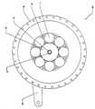
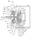
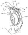
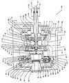
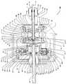
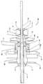
도1 및 도2를 참조하면, 연속 가변 변속기(100)의 실시예가 개시된다. 변속기(100)는 허브 외피(hub shell)(40)에 싸여 있는데, 이 허브 외피(또는 허브형 외피)(40)는 출력 디스크로서 기능하고 다양한 적용이 가능한 것이 바람직하며, (자전거나 모터사이클과 같은) 차량이 피동 휠 내에 수용되는 변속기를 갖는다. 허브 외피(40)는 특정 실시예에서, 허브 캡(67)으로 덮는다. 변속기(100)의 중심부에는 다수의 속력 조절기(1)가 있는데, 이들은 구의 형상일 수 있으며, 변속기(100)의 중심선 또는 회전축선을 중심으로 대칭으로 또는 동일하게 원주방향으로 다소간 이격되어 있다. 도시된 실시예에서 8개의 속력 조절기(1)가 사용된다. 그러나 알아두어야 할 것은 더 많은 또는 더 적은 속력 조절기(1)가 변속기(100)의 사용예에 따라 사용될 수 있다는 점이다. 예를 들면, 변속기는 3, 4, 5, 6, 7, 8, 9, 10, 11, 12, 13, 14, 15 또는 그 이상의 속력 조절기를 가질 수도 있다. 3, 4 또는 5 이상의 속력 조절기를 구비하는 것은 확실한 장점을 제공한다. 예를 들면, 개개의 속력 조절기(1) 및 변속기(100)의 다른 부품과의 접촉점에 가해지는 힘을 넓게 분산시킨다는 점이다. 낮은 토크에 높은 변속비의 특정 실시예에서는 적지만 큰 속력 조절기(1)를 사용할 수 있는 반면, 높은 토크와 높은 변속비의 특정 실시예에서는 많은 수의 큰 속력 조절기(1)를 사용할 수 있다. 높은 토크 낮은 변속비의 다른 실시예 에서는 많은 수의 작은 속력 조절기(1)를 사용할 수 있다. 나아가 낮은 토크와 낮은 변속비의 특정 실시예에서는 적은 수의 작은 속력 조절기(1)를 사용할 수 있다.1 and 2, an embodiment of a continuously
스핀들(3)은, 각 속력 조절기(1)의 회전 축선을 형성하는 각 속력 조절기(1)의 중심을 통하여 지나는 관통구멍에 삽입된다. 스핀들(3)은 대체로 기다란 샤프트인데 그를 중심으로 속력 조절기(1)가 회전하며, 속력 조절기(1)를 지나는 구멍의 각 끝단을 지나 연장되는 2개의 단부를 갖는다. 특정 실시예에서는 스핀들(3)은 원통형이지만, 다른 형상도 사용할 수 있다. 속력 조절기(1)는 스핀들(3)에 대하여 자유롭게 회전하도록 장착된다. 도1에서는 속력 조절기(1)의 회전축선은 대체로 수평방향으로 (즉, 변속기(100)의 중심축선과 평행으로) 도시되어 있다.The
도1, 도4, 도5는 속력 조절기(1)의 축선이 변속기(100)를 변속하도록 어떻게 틸팅 작동을 하는지 설명하는데 활용할 수 있다. 도4는 낮은 변속비 또는 낮은 단으로 변환된 변속기(100)를 도시하고, 도5는 높은 변속비 또는 높은 단으로 변환된 변속기(100)를 도시한다. 도9 및 도10을 또 참조하면, 다수의 스핀들 지지대(2)가 각 스핀들(3)의 각 단부 가까이에서 스핀들(3)에 결합되는데, 스핀들(3)은 속력 조절기(1)를 통하여 뚫린 구멍 외측으로 연장되며, 결합된 지점으로부터 변속기(100)의 축선을 향하여 반경방향 내측으로 연장된다. 일 실시예에서는, 각 스핀들 지지대(2)는 스핀들(3)의 일단부를 수용하는 관통구멍을 갖는다. 스핀들(3)은 그 끝이 노출되도록 스핀들 지지대(2)를 통하여 지나서 연장되는 것이 바람직하다. 도시한 실시예에서 스핀들(3)은 스핀들(3)의 노출된 말단과 동축으로 그리고 미끄럼가능하게 위치하는 스핀들 롤러(4)를 갖는 것이 유리하다. 스핀들 롤러(4)는, 스핀들 지 지대(2)를 지나서 바깥쪽에서 스핀들(3)에 축방향으로 고정된 대체로 원통형의 휠이며, 스핀들(3)을 중심으로 자유롭게 회전한다. 도11을 참조하면, 스핀들 롤러(4)와 스핀들(3)의 말단은 한 쌍의 정지 지지체(5a,5b)에 파인 홈(groove)(6) 안쪽에 끼워진다.1, 4 and 5 can be used to explain how the axis of the
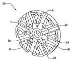
도4, 도5 및 도11을 참조하면, 정지 지지체(5a,5b)는 대체로, 동력 조절기(1)의 어느 한쪽에서 변속기의 축선에 대하여 고리모양으로 위치하는 평행 디스크의 형태이다. 속력 조절기(1)의 회전 축선은, 스핀들(3)이 틸팅하도록 변속기(100)의 축선으로부터 반경방향 바깥으로 스핀들 지지대(2)를 이동시켜서 변화시킬 때, 각 스핀들 롤러(4)는 정지 지지체(5a,5b) 중 하나에 파인 홈(6)에 끼워지게 되고 따르게 된다. 속력 조절기(1)가 스핀들(3)에 가할 수 있는 어떤 반경방향의 힘-회전이 아니고 축을 지나는 방향의 힘-은 스핀들(3), 스핀들 롤러(4)와 정지 지지체(5a,5b)의 홈(6)의 측부(81)에 흡수된다. 정지 지지체(5a,5b)는 변속기(100)의 축선을 따라 위치하는 분할 샤프트(98,99)에 장착된다. 분할 샤프트(98,99)는 변속기의 축방향 길이의 실질적인 부분을 형성하는 대체로 기다린 원통형의 것이고, 그것을 사용하는 대상물에 변속기(100)를 연결하는 데에 사용할 수 있다. 각 분할 샤프트(98,99)는 변속기(100)의 중간에 가까운 안쪽 말단과 변속기(100)의 내부 하우징의 외측으로 연장되는 바깥쪽 말단을 갖는다. 분할 샤프트(98,99)는 장착될 수 있는 다른 선택적인 부품들이 수용되도록 중공형인 것이 바람직하다. 정지 지지체(5a,5b)는 각각 관통구멍(82)을 가지는데, 그것을 통하여 분할 샤프트(98,99)가 삽입되고 견고하게 결합되어 분할 샤프트(98,99)와 정지 지지체(5a,5b) 사이의 어 떠한 상대적인 운동도 방지할 수 있다. 정지 지지체(5a,5b)는 분할 샤프트(98,99)의 말단에, 변속기(100)의 중심에서 가장 가깝게, 견고하게 결합되는 것이 바람직하다. 정지 지지 너트(90)가 분할 샤프트(99) 상에 나사 결합되고 정지 지지체(5a,5b)의 나사에 상응하게 정지 지지체(5b)에 대하여 죈다. 상기 정지 지지체(5a,5b)에 있는 홈(6)은 정지 지지체(5a,5b)의 바깥 원주로부터 분할 샤프트(98,99)를 향하여 반경방향 안쪽으로 연장된다. 대부분의 실시예에서, 홈(6)의 측면(또는 측벽)(81)은 실질적으로 평행하여 변속기(100)가 변속할 때 스핀들 롤러(4)가 홈 측면(81)을 굴러 올라가거나 내려올 수 있게 해준다. 또한, 특정 실시예에서는, 홈(6)의 깊이가 정지 지지체(5a,5b)의 원주(9)에서 실질적으로 일정하지만, 홈(6)의 깊이는 분할 샤프트(98,99)에 더 가까운 지점(7)에서 솟아올라, 스핀들(3)이 틸팅할 때 스핀들(3)의 끝단이 그리는 원호에 대응할 수 있고, 정지 지지체(5a,5b)의 강도를 증가시킨다. 변속기(100)가 속력 조절기(1)의 회전 축선을 변화시킴으로써 낮은 또는 높은 변속비로 변속할 때, 스핀들(3)의 대향 말단에 위치하는 각각의 하나의 스핀들 롤러(4)는 상응하는 홈(6)을 따라 반대방향으로 이동한다.4, 5 and 11, the
도9 및 도11을 참조하면, 정지 지지 휠(30)이 스핀들 지지체(2)에 정지 지지 휠 핀(31) 또는 어떠한 다른 결합 방법으로 결합될 수 있다. 정지 지지 휠(30)은 정지 지지 휠 핀(31)에 동축으로 미끄럼가능하게 장착되는데 예를 들면 링 클립과 같은 표준 체결구로 고정할 수 있다. 특정 실시예에서는, 하나씩의 정지 지지 휠(30)이 스핀들 지지대(2)의 각 측면에 충분한 틈새를 가지고 위치하여, 변속 기(100)가 변속할 때 정지 지지체(5a,5b)의 볼록한 표면(84) 상에서 구를 수 있게 한다. 특정 실시예에서는 볼록면(84)이 속력 조절기(1)의 중심과 동심을 이룬다.9 and 11, the
도2, 도3 및 도11을 참조하면, 다수의 기다란 스페이서(8)가 변속기의 축선을 중심으로 반경방향으로 분포되고, 축방향으로 연장된다. 기다란 스페이서(8)는 정지 지지체(5a)를 다른 하나의 지지체와 연결하여 변속기(100)의 내부구조의 견고성과 강도를 증가 시킨다. 스페이서(8)는 대체로 서로 평행으로 배향되며, 몇몇 실시예에서는, 각각이 하나의 정지 지지체(5a)에서의 바깥 원주에 가까운 지점으로부터 다른 정지 지지체(5b)의 상응하는 지점까지 연장된다. 이 스페이서(8)는 또한 정밀하게 정지 지지체(5a,5b) 사이의 거리를 고정시키고, 정지 지지체(5a,5b)의 홈(6)을 정렬시키며, 정지 지지체(5a,5b)가 평행이 되도록 보장하며, 분할 샤프트(98,99) 사이의 연결을 형성한다. 하나의 실시예에서는, 스페이서(8)가 정지 지지체(5a,5b)에 있는 스페이서 구멍(46)에 압입된다. 8개의 스페이서(8)가 도시되어 있지만, 그 이상 또는 이하의 스페이서(8)가 사용될 수 있다. 특정 실시예에서는, 스페이서(8)는 두 속력 조절기(1)사이에 위치한다.2, 3 and 11, a plurality of
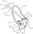
도1, 도3 및 도13을 참조하면, 정지 지지체(5a)는, 특정 실시예에서, 분할 샤프트(98,99) 주위로 동축으로 위치하는 정지 지지 슬리브(42)에 견고하게 결합되어 있으며, 또는 이와는 달리, 분할 샤프트(98)에 결합되거나 분할 샤프트(98)와 일체가 되는 부품을 만든다. 정지 슬리브(42)는 허브 외피(40) 벽을 통하여 연장되고 프레임 지지체(15)에 결합된다. 몇몇 실시예에서, 프레임 지지체(15)는 정지 슬리브(42)에 동축으로 설치되고 정지 슬리브(42)에 견고하게 결합된다. 몇몇 실시예 에서는, 프레임 지지체(15)는 토크 레버(43)를 사용하여 정지 슬리브(42)의 정지 위치를 유지한다. 토크 레버(43)는 정지 슬리브(42)를 프레임 지지체(15), 그리고 정지 부품들의 나머지를 거쳐, 변속기(100)가 장착될 물품의 고정된 지지 부재에 물리적으로 연결함으로써 변속기(100)에 회전 안정성을 부여한다. 토크 너트(44)는 정지 슬리브(42)의 최측에 나사 결합되어 토크 레버(43)를 프레임 지지체(15)에 결합되는 위치에 유지시켜준다. 특정 실시예에서, 프레임 지지체(15)는 토크 레버(43)와 결합하여 정지 슬리브(42)의 회전을 방지하도록 확실하게 결합하기 위해 원통형이 아닌 형상이다.1, 3, and 13, the
예를 들면, 프레임 지지체(15)는 토크 레버(43)와 두께가 같은 정사각형 형상일 수 있는데, 토크레버는 정지 슬리브보다 큰 측면을 가지며, 정사각형 부분이 정지 슬리브(42)에 끼워질 수 있게 중심에 뚫린 구멍을 구비하며, 정지 슬리브와 견고하게 결합될 수 있다. 추가적으로 토크 레버(43)는, 프레임 지지체(15)의 두께와 동일한 두께의 레버 암(lever arm)일 수 있으며, 프레임 지지체(15)에 가까운 제1단부와 제1단부의 반대편의 제2단부를 갖는다. 몇몇 실시예에서 토크 레버(43)는, 또한 일 단부를 관통하는 구멍을 갖는데, 이 구멍은 정사각형이고 프레임 지지체(15)보다 약간 커서 토크 레버(43)가 프레임 지지체(15) 위로 미끄러질 수 있으며 프레임 지지체(15)와 토크 레버(43)의 함께 회전할 수 있는 결합이 이루어진다. 게다가 토크 레버(43)의 레버 암은, 제2단부가 변속기(100)가 적용되는 자전거, 자동차, 트랙터 또는 다른 적용 물품의 프레임에 결합할 수 있게 연장되는 배향을 갖는데, 그럼으로써 프레임 지지체(15)와 정지 슬리브(42)를 통한 변속기(100)에 의 해 가해지는 어떠한 토크에도 대응할 수 있다. 정지 지지 베어링(48)은 허브 외피(40)의 외측 모서리와 토크레버(43) 사이에 축방향으로 정지 슬리브(42) 주위에 동축으로 끼워진다. 정지 지지 베어링(48)은 허브 외피(40)를 지지하는데, 허브 외피(40)가 정지 지지 슬리브(42)에 대하여 상대적으로 회전할 수 있게 한다.For example, the
도1과 도10을 참조하면, 몇몇 실시예에서 변환은 중공형 분할 샤프트(98) 안에 위치한 회전 막대(10)에 의해 수동으로 이루어진다. 몇몇 실시예에서 일련의 수나사인 웜 스크루(11)는 회전 막대(10)의 반대편 끝은 변속기(100)의 바깥쪽으로 축방향으로 연장되는 동안 변속기(100)의 중심에 있는 회전 막대(10)의 한쪽 끝에 결합되며, 웜 스크루(11)는 그 바깥 표면에 부가된 수나사를 구비한다. 일 실시예에서 웜 스크루(11)는, 막대(10)와 웜 스크루(11)가 회전하면 슬리브(19)가 축방향으로 이동하도록, 짝을 이루는 나사와 동축 슬리브(19) 안에서 나사결합된다. 슬리브(19)는, 웜 스크루(11)와 막대(10) 주위에 동축으로 끼워지는 대체로 중공형 실린더 형상이고, 양 단부를 갖는데, 한쪽 말단은 정지 지지체(5a)에 가깝고 다른 쪽 말단은 정지 지지체(5b)에 가깝다. 슬리브(19)는 말단에 플랫폼(13,14)이 결합된다. 두 플랫폼(13,14)은 각각 슬리브(19)와 결합되고 슬리브에 끼워지도록 충분한 크기의 내경을 갖는 고리형상으로서, 두 측면을 갖도록 형상이 이루어진다. 제1측면은 대체로 편평한 면으로서, 두 일련의 접촉 베어링(17a,17b)를 거쳐 지지부재(18)와 동적으로 접촉하며 축방향으로 지지하는 면이다. 각 플랫폼(13, 14)의 제2측면은 볼록한 표면 형상이다. 플랫폼(13, 14)은 각각 슬리브(19)의 바깥쪽 끝단에 결합되어 슬리브(19)의 원주 주위로 고리모양을 형성한다. 하나의 플랫폼(13)은 가장 가까운 정지 지지체(5a) 면에 결합되고, 다른 플랫폼(14)은 가장 가까운 정지 지지체(5b)의 끝에 결합된다. 플랫폼(13,14)의 볼록한 표면은 캠으로 작용하며, 다수의 시프트 휠(21)과 각각 접촉하며 밀어낸다. 캠으로서의 기능을 수행하기 위하여, 플랫폼(13,14)은 그 가장자리(분할 샤프트(98, 99)로부터 가장 먼) 근처에서, 그것이 반경을 형성할 수도 있고 아닐 수도 있는데, 볼록 곡면(97)이 되는 것이 바람직하다. 이 곡면(97)은, 플랫폼(13, 14)이 축방향으로 움직일 때, 분할 샤프트(98, 99)로부터 또는 분할 샤프트(98, 99) 쪽으로 스핀들 지지대(2)를 반경방향 힘을 가하고, 시프트 휠(shifting wheel)(21)이 대체로 반경방향으로 플랫폼(13,14) 표면을 따라 타고다니며, 그럼으로써 스핀들(3)와 당해 속력 조절기(1) 회전축의 각도를 변화키도록, 시프트 휠(21)과 접촉한다. 특정 실시예에서 시프트 휠(21)은 변속기(100)의 중심선에 가장 가까운 스핀들 지지대(2)의 슬롯 안에 끼워지고 휠 굴대(22)에 의해 적절한 위치에 유지된다.1 and 10, in some embodiments the conversion is made manually by a rotating
계속해서 도1과 도10을 참조하면, 지지부재(18)는 플랫폼(13, 14)과 슬리브(19) 사이에 형성된 골에 위치하고, 따라서 플랫폼(13, 14)과 슬리브(19)와 함께 움직인다. 특정 실시예에서, 지지부재(18)는 대체로 하나의 외경을 가지며 그 내경의 중심을 따라 대체로 원통형이고, 그 내경의 각 가장자리에 베어링 레이스를 갖는다. 다른 실시예에서는 지지부재(18)의 외경은 균일하지 않고 경사지거나 굽어진 것과 같은 어떠한 형상을 가질 수 있다. 지지부재(18)는 두 측면을 구비하는데, 정지 지지체(5a)에 가까운 하나와 다른 정지 지지체(5b)에 가까운 또 하나가 있다. 지지부재(18)는, 지지부재(18)와 슬리브(19) 사이의 구름 접촉을 제공하도록 두 접 촉 베어링(17a, 17b) 위에 얹어진다. 슬리브(19)가 플랫폼(13, 14)과 교차하는 곳에서 접촉 베어링(17a, 17b)은 슬리브(19) 주위에 동축으로 위치하고, 지지부재(18)가 변속기(100)의 축선을 중심으로 자유롭게 회전할 수 있도록 허용한다. 슬리브(19)는 웜 스크루(11)와 막대(10)에 의해 축방향으로 지지되고, 따라서 이러한 구조에 의해 슬리브(19)는 웜 스크루(11)가 위치시키는 대로 축방향으로 이동할 수 있다. 변속기(100)가 변속될 때, 슬리브(19)는 축방향으로 움직이고, 슬리브에 대하여 모두 이동할 수 있게 또는 고정적으로 결합된 베어링(17a, 17b), 지지부재(18) 및 플랫폼(13, 14)은 상응하여 축방향으로 움직인다.1 and 10, the
특정 실시예에서, 막대(10)는 웜 스크루(11)의 반대편 끝단에서 막대 너트(51)와 막대 플랜지(52)에 의해 시프트 튜브(shifting tube)(50)에 결합된다. 시프트 튜브(변환 튜브)(50)는 대체로 튜브 형상으로서 한쪽 끝은 개방되고, 다른 쪽 끝은 실질적으로 닫혀있다. 시프트 튜브(50)의 개방된 끝은 변속기(100)의 중심부로부터 축방향으로 연장되는 분할 샤프트(98)의 끝단이 끼워지기에 적절한 직경을 갖는다. 시프트 튜브(50)의 실질적으로 막힌 끝은 관통하는 작은 구멍을 구비하는데, 시프트 튜브(50)가 분할 샤프트(98)의 바깥쪽 부분에 위치할 때 웜 스크루(11)의 반대편 막대(10)의 끝단이 그 구멍을 통해 지나간다. 시프트 튜브(50)의 실질적으로 막힌 끝은 시프트 튜브(50)의 바깥에서 체결되는 막대 너트(51)와 시프트 튜브(50)의 실질적으로 막힌 끝의 내부에서 조여지는 막대 플랜지(52) 각각에 의해 축방향 적절한 위치에 고정될 수 있다. 몇몇 실시예에서 시프트 튜브(50)는 시프트 튜브(50)의 외부에 결합되는 케이블(53)에 의해 회전할 수 있다. 이 실시예에서 케 이블(53)은 케이블 클램프(54)와 케이블 나사못(56)으로 시프트 튜브(50)에 결합되고, 시프트 튜브(50) 주위를 감싸고 있어, 장력이 케이블에 적용될 때 회전을 야기시키는 시프트 튜브(50)의 축선의 중심에 대한 모멘트가 생성된다. 이와는 달리, 시프트 튜브(50)의 회전은 막대와 같은 어떤 다른 기구, 손에 의한 회전, 서보 모터, 또는 막대(10)를 회전시키기 위해 고려되는 다른 방법에 의해 이루어질 수도 있다. 특정 실시예에서 시프트 튜브(50)가 분할 샤프트(98)상에서 시계방향으로 회전하도록 케이블(53)이 당겨질 때, 웜 스크루(11)는 시계방향으로 회전하고, 슬리브(19), 지지부재(18) 및 플랫폼(13, 14)을 축방향으로 시프트 튜브(50)쪽으로 당기며 변속기(100)는 낮은 변속비가 된다. 도3에 도시된 바와 같이, 웜 스프링(55)은 압축과 비틀림 힘을 발생시키는 원뿔형 코일스프링일 수 있는데, 웜 스크루(11)의 끝단에 결합되며, 정지 지지체(5b)와 플랫폼(14) 사이에 위치하고, 변속기(100)의 변환에 저항한다. 웜 스프링(55)은 시프트 튜브(50)가 회전하도록 하게끔 설계되는데, 몇몇 실시예에서는 변속기(100)가 낮은 변속비로 변환하도록 하게끔 그리고 다른 실시예에서는 높은 변속비로 변환하도록 시프트 튜브(50)가 회전하도록 하게끔 설계된다.In a particular embodiment,
도1, 도10 및 도11을 참조하면, 플랫폼(13, 14)의 축방향 운동은 변속기(100)의 변환 범위를 규정한다. 축방향 운동은 플랫폼(13, 14)이 접하게 되는 정지 지지체(5a, 5b)의 안쪽 면(85)에 의해 제한된다. 극도로 높은 변속비에서 플랫폼(14)은 정지 지지체(5a, 5b) 중 하나의 안쪽 면(85)에 접촉하고, 극도로 낮은 변속비에서 플랫폼(13)은 정지 지지체(5a, 5b)의 다른 하나의 안쪽 면(85)에 접촉한 다. 많은 실시예에서 플랫폼(13, 14)의 볼록한 반경의 곡률은 속력 조절기(11)의 중심으로부터 휠(21)까지의 거리, 휠(21)의 반경, 각 속력 조절기(1)에 작동가능하게 결합된 두 휠(21) 사이의 거리, 및 속력 조절기(1) 축선의 틸팅 각도에 기능적으로 의존한다.1, 10 and 11, the axial movement of the
왼나사인 웜 스크루(11)를 개시하고 있지만, 오른쪽 방향으로 감싸는 시프트 튜브(50)에 상응하는 오른나사의 웜 스크루(11)와 바로 위에서 언급한 구성품의 어떠한 다른 조합도, 지지부재(18)와, 플랫폼(13, 14)의 횡방향 운동을 지지하는데 사용가능하다면 사용될 수 있다. 추가적으로 시프트 튜브(50)는 분할 샤프트(98)의 외측의 수나사와 결합되는 암나사를 구비한다. 이 나사결합을 추가함으로써 시프트 튜브(50)는 분할 샤프트(98)에 대하여 회전할 때 축방향으로 움직일 것이고, 막대(10)가 축방향으로 이동하도록 할 것이다. 이는 기어비를 보다 빨리 변환하기 위해 회전하는 웜 스크루(11)의 효과를 증폭하도록 웜스크류(11)에 의한 슬리브(19)의 축방향 이동을 향상시키기 위해, 또는 이와는 달리 변환 과정을 느리게 하여 변속기(100)를 보다 정확하게 조정하도록 웜 스크루(11)를 회전시키는 효과를 줄이기 위해 채용될 수 있다.While the left
도10과 도18을 참조하면, 수동 변환은 회전 손잡이(132)를 이용함으로써 이루어질 수 있는데, 이 회전손잡이(132)는 정지 튜브, 손잡이 막대(130) 또는 어떤 다른 구조적 부재 상에 동축으로 위치하는 것이다. 특정 실시예에서 케이블(53)의 끝단은 케이블 스톱(133)에 결합되는데, 이는 회전 손잡이(132)에 결합된 것이다. 몇몇 실시예에서 변속기(100)와 원뿔 스프링(55)의 내재적 힘은 변속기를 낮은 변 속비로 바꾸도록 하는 경향을 갖는다. 회전 손잡이(132)가 사용자에 의해 회전하면, 회전 손잡이(132) 주위에서 홈을 따라 감싸진 것일 수 있는 케이블(53)은 케이블(53)의 회전방향에 따라 감기거나 풀리며, 동시에 시프트 튜브(50)가 회전하고 변속기(100)가 높은 변속비 쪽으로 변한다. 일련의 래칫 톱니(ratchet teeth)(134)가, 래칫 튜브(135)의 제1측면에 짝을 이루는 일련의 래칫 톱니에 결합하도록, 회전 손잡이(132)의 양측면 중 한쪽면 주위에 위치할 수 있는데, 그럼으로써 회전 손잡이(132)가 반대방향으로 회전하는 것을 방지한다. 가변 클램핑력을 허용하는 조절식 스크루일 수 있는 튜브 클램프(136)는 래칫 튜브(135)를 손잡이 막대(130)에 고정한다. 반대방향으로 변환할 때, 회전 손잡이(132)는 낮은 변속비쪽으로 반대방향으로 강제로 회전되고, 회전 손잡이(132)에 맞추어 튜브 클램프(136)가 회전하게 한다. 래칫 톱니(134) 반대편에 래칫 튜브(135)에 가깝게 위치하는 손잡이막대 튜브(137)는 튜브 클램프(138)로 손잡이막대(130)에 견고하게 클램핑하고, 그럼으로써, 래칫 튜브(135)가 래칫 톱니(134)로부터 분리되는 것을 방지한다. 비회전 손잡이(131)는 손잡이막대(130)에 고정되고 회전 손잡이(132) 근처에 위치하며, 회전 손잡이(132)의 축방향 운동을 방지하고 래칫 톱니(134)가 래칫 튜브(135)로부터 분리되는 것을 방지한다.Referring to Figures 10 and 18, manual conversion can be accomplished by using a
도1, 도9 및 도11에 도시된 실시예를 참조하면, 하나 또는 그 이상의 정지 지지체 롤러(30)는 각 스핀들 지지체(2)의 구멍을 통해 삽입된 롤러핀(31)을 구비하는 각 스핀들 지지체(2)에 결합될 수 있다. 롤러핀(31)은 적절한 크기를 가지며 각 정지 지지체 롤러(30)가 롤러핀(31)에 위에서 자유롭게 회전할 수 있도록 설계 된다. 정지 지지체 롤러(30)는 속력 조절기(1)를 향하는 정지 지지체(5a, 5b)의 측면 위에 형성된 오목한 곡면(84)을 따라 구른다. 정지 지지체 롤러(30)는, 스핀들 지지체(2)가 축방향으로 움직이는 것을 방지하고 또한 변속기(100)가 변환할 때 스핀들(2)이 쉽게 경사지는 것을 보장하기 위한 축방향 지지구조를 제공한다.1, 9 and 11, one or more
도1, 도12, 도14, 및 도17을 참조하면, 정지 지지체(5b) 근처에 위치하는 세 개의 스포크(spoke)를 갖는 구동 디스크(34)는 부분적으로 정지 지지체(5b)를 감싸기는 하지만, 대체로 정지 지지체(5b)와는 접촉하지 않는다. 구동 디스크(34)는 두 개 또는 그 이상의 스포크를 구비할 수도 있고 솔리드 디스크일 수도 있다. 스포크를 이용한 실시예에서 스포크는 무게를 줄이고 변속기(100)의 조립을 돕는다. 그러나 솔리드 디스크가 사용될 수도 있다. 구동 디스크(34)는 양측을 구비하는데, 제1 측은 속력조절기(1)에 접촉하고 제2 측은 제1 측의 반대쪽을 향한다. 구동 디스크(34)는 대체로 고리모양의 디스크로서, 그 내경 안에 있는 일련의 암나사 세트 또는 너트(37)에 동축으로 끼워지며 그로부터 반경방향으로 연장된다. 채용된 허브 외피(40)가 속력 조절기(1)와 구동 디스크(34)를 감싸며 허브 캡(67)과 결합되는 형태라면, 구동 디스크(34)의 외경은 허브 외피(40) 안쪽에 설치되도록 설계된다. 구동 디스크(34)는 구동 디스크(34)의 제1 측의 가장자리에서 원주 베어링 표면 주위를 따라서 속력 조절기(1)에 회전가능하게 연결된다. 위에서 언급된 바와 같이, 구동 디스크(34)의 몇몇 실시예는 그 중심에 일련의 암나사(37) 또는 너트(37)를 구비하며, 너트(37)는 스크루(35)와 나사결합되고, 그럼으로써 구동 디스크(34)와 스크루(35)가 결합된다. 스크루(35)는 대체로, 분할 샤프트(99) 위에 동축으로 위 치하는 고리형 디스크 상의 융기된 표면인 중앙 스크루 램프 세트(90)에 견고하게 결합된다. 중앙 스크루 램프(90)는 중앙 구동 샤프트 램프 세트(91)에 의해 구동되는데, 중앙 구동 샤프트 램프(91)은 대체로 고리형 디스크 상에 유사하게 형성된 것이다. 중앙 구동 램프(91)와 중앙 스크루 램프(90)의 램프 표면을 직선형일 수 있는데, 다른 형태일 수도 있으며, 서로 작동 가능하게 접촉된다. 구동 샤프트(69)에 견고하게 동축으로 결합되는 중앙 구동 샤프트 램프(91)는, 결국 구동 디스크(34)로 전달될 수 있는 토크와 축방향 힘을 중앙 스크루 램프(90)로 전한다. 중앙 구동 샤프트 램프(91)와 중앙 스크루 램프(90) 사이에 위치한 중앙 구동 장력 부재(92)는 비틀림 힘 및/또는 압축 힘을 생성하고 중앙 램프(90, 91)의 상호 접촉을 보장한다.1, 12, 14, and 17, the
계속해서 도1, 도12, 도14, 및 도17을 참조하면, 축방향으로 움직일 수 있는 스크루(35)는 속력 조절기(1)로부터 축방향으로 먼 쪽으로 움직이도록 편향될 수 있는데, 속력 조절기(1)를 향하는 스크루(35)의 일측면 위의 레이스와 접촉하는 고리형 스러스트 베어링(73)이 구비된다. 분할 샤프트(99)와 동축으로 위치하는 고리형 스러스트 베어링 와셔(72)는, 스러스트 베어링(73)과 접촉하고 분할 샤프트(99)의 슬롯을 통해 연장된 핀(12)에 의해 밀릴 수 있다. 압축 힘을 생성할 수 있는 압축부재(95)는 중공형인 분할 샤프트(99)의 제1 단의 구멍 안에 위치한다. 스프링일 수도 있는 압축부재(95)는 한쪽 끝이 핀(12)과 접하고, 다른 쪽 끝은 막대(10)와 접한다. 막대(10)가 보다 높은 변속비 쪽으로 변환되어 축방향으로 이동하면, 막대(10)는 압축부재(95)와 접하고 압축부재(95)를 핀(12)에 대하여 밀어 낸다. 일단 변속비가 1:1을 지나 높아지면 변속기(100)의 내재된 힘은 지지부재(18)가 높은 변속비 위치로 이동하도록 편향시킬 것이고, 구동 디스크(34)는 허브 외피(40)보다 더 천천히 회전한다. 이러한 편향은, 너트(37)로부터 분리되어 더 이상 축방향 힘 또는 토크가 구동 디스크(34)에 가해지지 않도록 하거나, 스크루(35)가 너트(37)에 가하는 힘을 줄이도록 스크루(35)를 축방향으로 밀어낸다. 이러한 상태에서는, 가장자리 램프(61)에 의해 구동 디스크(34)에 가해지는 축방향 힘의 비율은 증가한다. 일단 지지부재(18)가 1:1의 변속비 위치를 지나 더 낮아지면 변속기(100)의 내장된 힘은 또한 지지부재(18)를 낮은 변속비 쪽으로 편향시킬 것이며, 허브 외피(40)는 구동 디스크(34)보다 더 천천히 회전한다는 것을 주목해야 한다. 이러한 이로운 편향은, 낮은 변속비로 변환할 때 회전수 감소와 토크 증가로의 변환을 도와준다.1, 12, 14, and 17, the axially
계속해서 도1, 도12, 도14, 및 도17을 참조하면, 양단을 구비하는 대체로 관모양의 슬리브이고 분할 샤프트(99)의 외측에 동축으로 위치하는 구동축(69)은 한쪽 끝에서 전술한 중앙 구동 샤프트 램프(91)와 결합되는데, 반대쪽 끝은 구동 디스크(34)로부터 먼쪽을 향한다. 베어링 디스크(60)가 대체로 구동축(69)에 동축으로 위치하는 반경방향 디스크인데 구동 디스크(34)의 반경과 같은 반경까지 반경방향 바깥쪽으로 연장된다. 베어링 디스크(60)는 구동 디스크(34)에 가까운 위치에서 구동축(69)에 위치하나, 일련의 가장자리 램프(61), 연관된 램프 베어링(62), 베어링 마찰부(64), 구동 디스크(34)와 베어링 디스크(67) 사이에 위치한 모든 것을 위한 공간을 형성하도록 충분히 떨어져야 한다. 특정 실시예에서 다수의 가장자리 램 프(61)는 오목한 것일 수 있고, 구동 디스크(34)를 향하는 쪽에서 베어링 디스크(60)에 견고하게 결합될 수 있다. 이와는 달리 변속기(100)의 사용에 따라 가장자리 램프(61)는 볼록하거나 편평할 수도 있다. 이와는 달리 베어링 레이스(64)는 편평하거나, 볼록하거나, 또는 오목하고 베어링 디스크(60)를 향하는 쪽에서 구동 샤프트(34)에 견고하게 결합되는 제2의 일련의 가장자리 램프(97)에 의해 대체될 수 있다. 램프 베어링(62)은 대체로, 가장자리 램프(61)와 숫자를 맞춘 다수의 베어링이다. 다수의 램프 베어링(62) 중 각각의 하나는 가장자리 램프(61)와 베어링 레이스(64) 사이에 위치하고, 램프(61)와 베어링 케이지(cage)(63)에 의한 압축 힘에 의해 그 적절한 위치를 유지한다. 베어링 케이지(63)는 분할 샤프트(99)와 동축의 고리형 링이고 축방향으로 오목한 램프(61)와 볼록한 램프(64) 사이에 위치한다.1, 12, 14, and 17, the
베어링 케이지(63)는, 램프 베어링(62)을 감싸도록 베어링 케이지(63)의 반경방향 두께가 램프 베어링(62)의 직경보다 약간 클 뿐이게끔된 비교적 큰 내경을 가진다. 각 램프 베어링(62)은, 베어링 케이지(63)의 반경방향 두께 안에 형성된 구멍에 설치되고, 앞서 언급한 압축 힘과 함께 이 구멍들은 램프 베어링(62)을 제 위치에 유지시킨다. 베어링 케이지(63)는, 베어링 케이지(63)의 내경보다 약간 작은 구동 디스크(34) 또는 베어링 디스크(60)의 플랜지에 의해 적소로 안내될 수 있다.The bearing
도1, 도6, 도7, 도8, 및 도15를 참조하면, 베어링 디스크(60), 가장자리 램프(61), 및 램프 베어링(62)의 한 실시예가 도시되어 있다. 특히, 도6을 참조하면, 이 개략도는 오목 가장자리 램프(61)와 제2의 볼록 가장자리 램프(97)와 접하는 램프 베어링(62)을 보여준다. 특히, 도7을 참조하면, 이 개략도는 다른 토크 또는 변속비에서 도6의 램프 베어링(62), 오목 가장자리 램프(61), 및 제2의 볼록 가장자리 램프(97)를 보여준다. 도7에 도시된 가장자리 램프(61) 위의 램프 베어링(62)의 위치에서는 도6에 도시된 가장자리 램프(61) 위의 램프 베어링(62)의 위치에서보다 적은 축방향 힘이 생성된다. 특히, 도8을 참조하면, 램프 베어링(62)은, 대체로 각 램프의 중앙 위치에서 볼록 가장자리 램프(61)와 오목한 제2 가장자리 램프(97)와 접촉하는 것으로 도시되어 있다. 가장자리 램프(61, 97)의 곡선의 변화는, 가변 변속비에서 동력 조절기(1)에 적용되는 축방향 힘의 크기를 변화시키며, 그럼으로써 다른 기어비에서의 효율과 토크의 변화를 극대화한다는 점을 주목해야 한다. 변속기(100)의 용도에 따라, 곡선 또는 직선의 가장자리 램프(61, 97)의 많은 조합이 사용될 수 있다. 동작을 단순화하고 비용을 줄이기 위해서, 몇몇 적용예에서는 제2의 가장자리 램프 세트(97)와 같은 하나의 가장자리 램프 세트가 제거될 수도 있는데, 이는 베어링 레이스(64)에 의해 대체될 수 있다. 비용을 더 줄이기 위해서 가장자리 램프 세트(61)은 직선의 경사를 가질 수도 있다.1, 6, 7, 8, and 15, one embodiment of a
도1을 참조하면, 양단을 구비하는 코일 스프링(65)은 구동 샤프트(69) 주위를 동축으로 감싸는데, 일단은 베어링 디스크(60)에 결합되고, 반대편 단은 구동 디스크(34)에 결합된다. 코일 스프링(65)은 구동 디스크(34)와 속력 조절기(1)의 접촉을 유지시키는 힘을 제공하며, 램프 베어링(62)을 가장자리 램프(61)로 편향시킨다. 코일 스프링(65)은 작동에 필요한 축방향 공간을 최소화하도록 설계되는데, 특정 실시예에서 코일 스프링(65)의 단면은 축방향 길이보다 더 큰 반경방향 길이를 가지는 직사각형이다.Referring to Figure 1, a
도1을 참조하면, 베어링 디스크(60)는 바람직하게는, 베어링 디스크(60)의 오목 램프(61)의 반대편을 향하는 베어링 디스크(60) 측에서 외측 허브캡 베어링(66)에 접한다. 외측 허브캡 베어링(66)은 변속기(100)의 중심선의 반경방향 바깥쪽으로 동축으로 위치하는 고리형의 일련의 롤러 베어링일 수 있다. 외측 허브캡 베어링(66)은, 서로에 대하여 그들의 상대운동을 허용하도록 허브캡(67)과 베어링 디스크(60) 모두에 접촉할 수도 있는 위치에 반경방향으로 놓인다. 허브캡(67)은 대체로 구동 샤프트(69)에 꼭 맞는 중앙의 구멍을 가지며 허브 외피(40) 내에서 꼭 맞게 설치되는 외경을 갖는 디스크 형상이다. 허브캡(67)은, 구동 샤프트(69)에 끼워지도록 중앙에 구멍을 가지며 허브 외피(40)에 끼워지도록 외경을 갖는 대체로 디스크의 형상이다. 허브캡의 내경은, 허브캡(67)과 구동 샤프트(69) 사이에 위치하는 내부 허브캡 베어링(96)과 결합되고, 허브캡(67)과 구동 샤프트(69)의 서로에 대한 반경방향 및 축방향 정렬을 유지한다. 허브캡(67)의 외경에서의 가장자리는, 그 내부에 변속기(100)의 많은 부분을 수용하기 위하여 허브캡(67)이 허브 외피(40) 내로 결합되도록 나사결합될 수 있다. 스프로킷 또는 풀리(38) 또는 예를 들면 전동장치와 같은 다른 트래인 어댑터는 회전입력을 제공하도록 회전 구동 샤프트(69)에 견고하게 결합될 수 있다. 구동 샤프트(69)는 콘 베어링(70)에 의해 분할 샤프트(99)와 동축방향의 위치에 유지된다. 콘 베어링(70)은 분할 샤프트(99) 주위에 동축으로 장착된 고리형 베어링이며, 구동 샤프트(69)와 분할 샤프트(99) 사이의 구름접촉을 허용한다. 콘 베어링(70)은 분할 샤프트(99)로 나사결합되는 콘 너트(71) 또는 다른 체결 방법에 의해 축방향 위치가 유지될 수 있다.Referring to FIG. 1, the
특정 실시예의 동작에 있어서, 스프로킷 또는 풀리(38)로부터의 회전입력은 구동 샤프트(69)으로 전달되고, 차례로 베어링 디스크(60)와 다수의 가장자리 램프(61)를 회전시키고, 램프 베어링(62)이 가장자리 램프(61) 위로 구르도록 하고 속력 조절기(1)에 대항하여 구동 디스크(34)를 가압하게 한다. 또한 램프 베어링(62)은, 가장자리 램프(61)와 볼록 램프(64)의 중간에 박혀 있어서 회전에너지를 전달함으로써, 회전 에너지를 구동 디스크(34)로 전달한다. 회전 에너지는 구동 디스크(34)로부터 속력 조절기(1)로 전달되고, 차례로 변속기(100) 출력 회전과 토크를 제공하는 허브 외피(40)를 회전시킨다.In operation of a particular embodiment, rotational input from the sprocket or
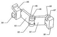
도16을 참조하면, 래치(latch)(115)는 구동 디스크(34)의 베어링 디스크(60)를 향하는 쪽에 견고하게 고정되며, 후크 레버(113)의 두 단부 중 제1 단부에 견고하게 결합된 후크(114)와 결합된다. 래치(115)의 개방부 아래의 결합 영역은 후크(114)의 폭보다 크고, 구동 디스크(34)와 베어링 디스크(60)가 서로 상대적으로 움직일 때 후크(114)가 래치(114)의 영역 내에서 축선에 대하여 반경방향으로 움직이도록 여유 공간을 제공한다. 후크 레버(113)는 대체로 후크(114)를 위한 길이방향의 지지부재이고, 제2 단부에서 후크 레버(113)는 제1 힌지핀(111)을 거쳐 중간 힌지(119)와 결합되는 일체형 후크 힌지(116)를 구비한다. 중간 힌지(119)는 구동 디스크 레버(112)의 제1 단부와 일체인 것이며, 대체로 기다란 지지부재는 두 단부를 갖는다. 제2 단부에서, 구동 디스크 레버(112)는 제2 힌지 핀(118)의 사용을 통 해 힌지 버팀대(110)에 결합되는 일체의 구동 디스크 힌지(117)를 구비한다. 힌지 버팀대(110)는 대체로 후크(114), 후크 레버(113), 후크 힌지(116), 제1 힌지핀(111), 중간 힌지(119), 구동 디스크 레버(112), 제2 힌지 핀(118), 및 구동 디스크 힌지(117)를 지지하기 위한 베이스이고, 구동 디스크(34)를 향하는 면 위에서 베어링 디스크(60)와 견고하게 결합된다. 래치(73)과 후크(72)가 결합되었을 때, 램프 베어링(62)이 축방향 힘의 정확한 양을 구동 디스크(34)에 제공하지 않는 가장자리 램프(61) 상의 범위까지 구르는 것이 방지된다. 이것은 가장자리 램프(61)에 의해 램프 베어링(62)에 가해지는 모든 회전력이 구동 디스크(34)로 전달되는 것을 보장한다.Referring to Fig. 16, the
도1과 도17을 참조하면, 변속기(100)의 일 실시예를 위한 분리 기구가 관성운전(타력운전)을 위해 속력 조절기(1)로부터 구동 디스크(34)를 분리하는 것으로 개시되어 있다. 변속기(100)에 회전 입력이 중지되는 경우, 스프로킷 또는 풀리(38)는 회전을 멈추지만 허브 외피(40)와 속력 조절기(1)는 계속 회전할 수 있다. 이것은 구동 디스크(34)의 회전을 야기하여, 구동 디스크(34)의 구멍 내의 일련의 암나사(37)가 수나사 스크루(35) 위로 감아 나아가게 되고, 그럼으로써 구동 디스크(34)가 더 이상 속력 조절기(1)에 접촉하지 않을 때까지 구동 디스크(34)는 속력 조절기(1)로부터 먼 쪽으로 축방향으로 이동한다. 베어링 디스크(60)를 향하는 쪽의 구동 디스크(34)에 견고하게 결합된 톱니 래크(126)는 톱니를 구비하는데, 이것은 구동 디스크(34)가 스크루(35) 위를 감아 나아가고 동력 조절기(1)로부터 분리될 때 톱니 휠(124)과 맞물리고 휠을 회전시킨다. 톱니 휠(124)은 그 중심에 구멍을 구비하는데, 그 구멍을 통해 톱니 휠(124)의 회전을 위해 제공되는 톱니 휠 부싱(121)이 위치한다. 다른 어떠한 체결 수단이라도 사용될 수 있겠지만, 톱니 휠 부싱(121)에 동축으로 결합되는 클립(125)은 톱니 휠(124)을 제 위치에 고정한다. 중앙 구동 샤프트 램프(91)와 동축으로 중앙 구동 샤프트 램프(91)에 클램핑된 프리로더(preloader)(또는 예압장치, 예하중장치)(120)는 변속기(100)의 중심으로부터 반경방향 바깥쪽인 방향에서 연장된다. 굽혀졌을 때 원 상태로 돌아오도록 탄성 재료로 이루어진 프리로더는 제1 단부(128)와 제2 단부(127)를 구비한다. 프리로더의 제1 단부(128)는 톱니 휠 부싱(121) 통해 연장되고 베어링 케이지(63)에서 끝난다. 프리로더의 제1 단부(128)는 베어링 케이지(63)과 램프 베어링(62)을 램프(61) 위쪽으로 편향시키고, 램프 베어링(62)과 램프(61) 사이의 접촉을 보장하고, 또한 톱니 휠(124)을 톱니 래크(126)에 대항하여 편향시킨다. 멈춤쇠(pawl)(123)은 톱니 휠(124)에 결합되고 한 실시예에서는 톱니 래크(126)의 실질적인 반대쪽에서 톱니 휠(124)과 결합된다. 멈춤쇠(123)은 구멍을 구비하는데, 이 구멍을 통해 멈춤쇠 부싱(122)이 지나가며, 멈춤쇠(123)의 회전을 허용한다. 클립(125) 또는 다른 체결 수단이 멈춤쇠(123)을 멈춤쇠 부싱(121)에 고정시킨다. 멈춤쇠 스프링(122)은 톱니 휠(124)과 결합하도록 멈춤쇠(123)의 회전을 편향시키며, 그럼으로써 구동 디스크(34)가 스크루(35) 위를 감아 나아갈 때 톱니 휠(124)이 반대로 회전하는 것은 방지한다. 멈춤쇠 부싱(121)은 구동 샤프트(69)와 맞추어 회전하는 프리로더(127)의 제2 단부에 위치한다.1 and 17, a separation mechanism for one embodiment of the
도1을 다시 참조하면, 구동 샤프트(69) 주위에 위치하며 구동 샤프트(69)와 동축의 코일 스프링(65)은, 축방향으로 베어링 디스크(60)와 구동 디스크(34)의 사이에 위치하고, 핀 또는 다른 체결구(도시되지 않음)에 의해 베어링 디스크(60)에 한쪽 끝이 구동 디스크(34)에 다른쪽 끝이 결합된다. 특정 실시예에서 코일 스프링(65)은 변속기(100)의 전체 크기를 줄이기 위해서 보다 작은 축방향 공간을 차지하고 보다 큰 힘을 제공하도록 종래 기술의 코일스프링을 대신한다. 몇몇 실시예에서 코일 스프링(65)은 반경방향 길이 또는 높이가 축방향 길이 또는 폭보다 큰 직사각형 프로파일을 갖는 스틸 와이어 스프링으로부터 제작된다. 변속기(100)가 작동하는 동안 코일 스프링(65)은 속력 조절기(1)와 구동 디스크(34)를 확실히 접촉시킨다. 그러나 일단 구동 디스크(34)가 속력 조절기(1)로부터 분리되면, 톱니 휠(124)과 멈춤쇠(123)의 결합에 의해 구동 디스크(34)가 속력 조절기(1)와 다시 접촉하도록 코일 스프링(65)이 구동 디스크(34)에 감기는 것을 방지한다. 입력 스프로킷, 기어, 또는 풀리(38)가 다시 그 회전을 시작하였을 때, 멈춤쇠(123) 역시 회전하고, 톱니 휠(124)이 회전하는 것을 허용하게 되어, 구동 디스크(34)가 회전하고 코일 스프링(65)에 의해 만들어진 비틀림 힘에 의해 스크루(35)로부터 풀리게 한다. 멈춤쇠(123)과 톱니 휠(124) 사이의 상대 운동은, 프리로더의 제1 단부(128)가 베어링 케이지(63)에 결합되기 때문에, 프리로더의 제1 단부(138)는 프리로더의 제2 단부(127)의 대략 절반의 속력으로 회전한다는 사실에 의해 제공된다. 또한, 램프 베어링(62)은 베어링 디스크(60)의 가장자리 램프(61) 위를 구르기 때문에, 베어링 케이지(63)는 베어링 디스크(60)의 절반의 속력으로 회전할 것이다.Referring again to FIG. 1, a
도19를 참조하면, 도1의 변속기의 다른 실시예가 도시되어 있다. 본 실시예 에서 출력 디스크(201)는 도1에 도시된 변속기(100)의 허브 외피(40)를 대신한다. 구동 디스크(34)와 유사하게, 출력 디스크(201)는 속력 조절기(1)와 접촉하고, 속력 조절기(1)에 의해 회전한다. 출력 디스크(201)는 출력 디스크(201)와 정지 케이스 캡(204) 모두에 접촉하는 출력 디스크 베어링(202)에 의해 지지된다. 케이스 캡(204)은 정지 케이스(203)에 케이스 볼트(205) 또는 다른 체결구로 견고하게 결합된다. 정지 케이스(203)는 프레임과 같은 움직이지 않는 대상이나 변속기를 적용할 기계에 결합된다. 기어, 스프로킷, 또는 풀리(206)는 출력 디스크(201)에 케이스 캡(204)과 정지 케이스(203)의 외측에서 견고하게 동축으로 결합된다. 그러나 예를 들면 기어와 같은 출력 수단의 다른 형태도 사용될 수 있다. 비틀림 버팀대(207)가 추가되어, 추가적 지지체로서 분할 샤프트(98)를 케이스 캡(204)에 견고하게 연결할 수 있다.19, another embodiment of the transmission of FIG. 1 is shown. In this embodiment the
도20과 도21을 참조하면, 도1의 변속기(100)의 다른 실시예가 도시되어 있다. 정지 지지 레이스(stationary support race)(302)가 속력 조절기(1)로부터 먼쪽으로 향하는 정지 지지체(5a)의 일측 위에 추가되고, 회전 허브 외피(40)에 대한 정지 지지체(5a)의 정확한 정렬를 유지하기 위하여 정지 지지 베어링(301)과 회전 허브 외피 레이스(303)에 연결된다. 비틀림 버팀대(304)는 정지 지지체(5a)에 견고하게 결합되고, 따라서 변속기(300)가 작동하는 동안 정지 지지체(5a, 5b)가 회전하는 것을 방지하도록 정지 외부 구성품에 견고하게 결합될 수 있다. 구동 샤프트 베어링(306)은 속력 조절기(1)를 향하는 구동 샤프트(69)의 한쪽 끝에 위치하고, 구동 샤프트(69)의 동일한 끝에 형성된 구동 샤프트 레이스(307)와 구동 샤프 트(69)에 추가적 지지체를 제공하고 구동 샤프트(69)를 정지 지지체(5a, 5b)에 대해 상대적으로 적절하게 위치시키기 위해 분할 샤프트(99)의 반경방향으로 융기된 부분에 형성된 분할 샤프트 레이스(305)에 결합된다. 도20에 도시된 구성을 이용하는 실시예에서 동적 밀봉재(seal)(도시되지 않음)가 허브캡(67)의 내경과 그에 인접한 구동 샤프트(69) 위의 위치 사이에 둘이 자주 다른 속력에서 회전할 때 사용될 수 있다. 밀봉재(또는 실)는 먼지와 회전하는 허브(40) 내에서 생기는 파편의 양을 최소화하도록 사용될 수 있다.20 and 21, another embodiment of the
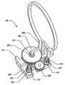
도22와 도23을 참조하면, 도1의 변속기(100)의 다른 분리기구(400)가 도시되어 있다. 톱니 휠(402)은 휠 부싱(408) 위에 동축으로 위치하고, 클립(413) 또는 회전할 수 있는 다른 체결구로 위치가 고정된다. 휠 부싱(408)은 제1, 제2 단부를 갖는 프리로더(405)의 제1 단부 위에 동축으로 위치한다(도22와 도23에는 둘 다 개별적으로 식별되지는 않는다). 프리로더(405)는 중앙 구동 샤프트 램프(91) 주위에 탄력있게 조여진다. 프리로더(405)의 제1 단부는 베어링 케이지(63) 안으로 연장되어, 베어링 케이지(63)를 가장자리 램프(61) 위로 편향시킨다. 또한 레버(401)는 휠 부싱(408) 위에 위치하며, 휠 부싱(408) 주위를 회전하고, 톱니 휠 멈춤쇠(411)과 피니언 멈춤쇠(409)을 지지한다. 톱니 휠 멈춤쇠(411)은 회전을 제어하기 위해 톱니 휠(402)과 결합하고, 레버(401) 내의 구멍 안으로 압입된 톱니 휠 부싱(414)에 위치한다. 톱니 휠 멈춤쇠 스프링(412)은 톱니 휠 멈춤쇠(411)을 톱니 휠(402)에 대하여 편향시킨다. 실질적으로 레버(401) 상의 톱니 휠 멈춤쇠(411) 반대편에 위치하는 피니언 멈춤쇠(409)은 레버(401) 안의 다른 구멍 안으로 끼워지고 피니언 멈춤쇠(409)의 회전 운동을 제공하는 피니언 멈춤쇠 부싱(415)과 동축으로 위치한다. 피니언 멈춤쇠 스프링(410)은 피니언 멈춤쇠(409)을 피니언(403)에 대하여 편향시킨다.22 and 23, there is shown another
도1, 도22, 및 도23을 참조하면, 피니언(403)은 그 중심에 구멍을 구비하고, 막대 레버(404)의 두 단부 중 제1 단부에 동축으로 위치한다. 막대 레버는 스프로킷, 풀리, 또는 기어(38)의 회전 입력이 다시 시작할 때까지 관성운전하는 동안, 피니언 멈춤쇠(409)과 결합하는 기다란 레버이다. 베어링 디스크(60)에 부가되는 베어링 디스크 핀(406)은 베어링 디스크(60)의 회전시 막대 레버(404)의 제2 단부와 접촉함으로써, 막대 레버(404)를 구동 디스크(34)에 견고하게 결합되는 구동 디스크 핀(407)에 대항하여 민다. 이러한 움직임은 막대 레버(404)의 제1 단부가 톱니 휠(402)로부터 멀어지게 흔들리도록 하고, 임시적으로 피니언(403)을 톱니 휠(402)로부터 분리하며, 톱니 휠(402)이 회전하도록 허용한다. 레버 후크(401)은 레버(401)에 결합되고 구동 디스크(34) 위의 래치(도시되지 않음)에 접촉하고, 그럼으로써 속력 조절기(1)를 풀고 접촉하도록 코일 스프링(65)이 구동 디스크(34)를 편향시킬 때 뒤로 밀린다. 스프로킷, 풀리, 또는 기어(38)의 회전 입력이 멈추어 있고 속력 조절기(1)가 계속 회전하는 동안, 구동 디스크(34)는 스크루(35) 위를 감아 나아가고 속력 조절기(1)로부터 분리된다. 구동 디스크(34)가 회전할 때, 구동 디스크 핀(407)은 막대 레버(404)로부터 분리되는데, 피니언(403)을 흔들어 톱니 휠(402)과 접촉시키고, 구동 디스크(34)가 속력 조절기(1)에 다시 결합되는 것을 막는다.1, 22, and 23, the
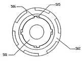
도24와 도25를 참조하면, 도20의 변속기(300)의 다른 일련의 축방향 힘 발생기의 서브어셈블리가 도시되어 있다. 입력 스프로킷, 기어 또는 풀리(38)에 의해 회전할 때, 스플라인 구동 샤프트(501)는, 스플라인 구동 샤프트(501)의 스플라인(506)을 수용하고 이와 결합하도록 구멍 안의 홈(505)을 구비할 수도 있는 베어링 디스크(60)를 회전시킨다. 중앙 구동 샤프트 램프(508)는 베어링 디스크(60) 또는 스플라인 구동 샤프트(501)에 견고하게 결합되고, 중앙 스크루 램프(507)를 회전시키는데 스플라인 구동 샤프트(501)의 스플라인(506)을 통과하는 구멍을 모두 구비한다. 중앙 장력 부재(92)(도1에 도시됨)는 중앙 구동 샤프트 램프(508)와 중앙 스크루 램프(507) 사이에 위치한다. 홈붙이 단부와 베어링 단부를 구비하는 홈붙이 스크루(502)는 중앙 스크루 램프(90)에 의해 회전하고, 스플라인(506)과 홈(505) 사이에 틈을 형성하기 위해 스플라인 구동 샤프트(501) 상의 스플라인(506)보다 더 넓은 홈(505)을 베어링 단부 상에 구비한다. 스플라인(506)과 홈(505) 사이의 이 틈은 홈 스크루(502) 및/또는 베어링 디스크(60)와 스플라인 구동 샤프트(501) 사이에 상대 운동을 허용한다. 홈 스크루(502)가 중앙 구동 샤프트 램프(508)와 중앙 스크루 램프(507)에 의해 회전하지 않는 경우에, 스플라인 구동 샤프트(501)의 스플라인(506)은 홈 스크루(502) 상의 홈(505)과 접촉하고 회전시켜, 홈 스크루(502)를 회전시킨다. 고리형 스크루 베어링(503)은 홈 스크루(502)의 베어링 단부 상의 레이스와 접촉하고, 분할 샤프트(99)의 축선에 대하여 홈 스크루(502)와 스플라인 구동 샤프트(501)를 지지하도록 위치한다. 홈 스크루(502)의 구멍은 홈 스크루(502)의 상대적인 축방향 운동과 회전운동을 허용하도록 스플라인 구동 샤프트(501)의 외경보다 약간 크다. 스크루 콘 레이스(504)는 고리형 스크루 베어링(503)과 접촉하며 결합하고, 핀(12)의 삽입을 허용하도록 그 축선에 수직인 구멍을 구비한다. 핀(12)은 핀(12)을 밀어 홈 스크루(502)를 축방향으로 움직일 수 있는 막대(10)와 결합하여, 너트(37)로부터 분리되거나 그것이 너트에 가하는 축방향 힘을 줄인다.Referring to Figures 24 and 25, a subassembly of another series of axial force generators of the
도26을 참조하면, 도22와 도23의 분리 수단(400)과 다른 분리 수단(600)이 개시되어있다. 레버(401)는 피니언 멈춤쇠(409)과 톱니 휠 멈춤쇠(411)을 장착하는데 사용되는 T-형상을 제거하도록 개조되어, 새로운 레버(601)는 톱니 휠 멈춤쇠(411)만을 구비한다. 제2 레버(602)는 제1, 제2 단부를 구비한다. 피니언 멈춤쇠(409)은 작동 가능하게 제2 레버(602)의 제1 단부에 결합된다. 제2 레버(602)는 제1 구멍을 구비하는데, 제1 구멍을 통해 프리로더(405)의 제1 단부가 삽입된다. 제2 레버(602)는 프리로더(405)의 제1 끝단 위로 회전가능하게 장착된다. 제2 레버(602)는 제2 단부에 제2 구멍을 구비하는데, 제2 구멍을 통해 프리로더(603)의 제2 단부가 삽입된다. 스프로킷, 기어, 또는 풀리(38)의 회전이 멈추었을 때, 구동 디스크(34)는 앞으로 계속 회전하고 속력 조절기(1)로부터 분리될 때까지 스크루(36) 위로 감아 나아간다. 프리로더(405)의 제1 단부는 앞으로 회전하여 피니언 멈춤쇠(409)가 피니언(403)과 접촉하여 피니언(403)을 시계방향으로 회전하도록 한다. 이것은 톱니 휠 멈춤쇠(411)이 톱니 휠(402)의 하나 또는 그 이상의 톱니를 지나가도록 톱니 휠(402)이 반시계방향으로 회전하도록 하고, 구동 디스크(34)를 고정하며 그것이 스크루(36)에 대해 풀리는 것과 속력 조절기(1)와 접촉하는 것을 방 지한다. 스프로킷, 기어 또는 풀리(38)의 회전이 다시 시작되었을 때, 프리로더(603)의 제2 단부가 회전하고, 제2 레버(602)의 제2 끝단과 접촉함으로써 피니언 멈춤쇠(409)가 밖으로 흔들려 피니언(403)과 분리되게 하고, 구동 디스크(34)가 풀리고 속력 조절기(1)와 다시 결합하는 것을 허용한다.Referring to Fig. 26, a separating means 600 different from the separating means 400 of Figs. 22 and 23 is disclosed. The
적절한 개소의 설명과 함께, 이제 본 발명의 특별한 개선점들과 장점이 기술될 것이다. 발명의 모든 실시예에서 이 개선점들이 모두 필연적으로 발견되는 것은 아니라는 점도 유념할 필요가 있다.With the description of the appropriate places, particular improvements and advantages of the present invention will now be described. It should be noted that not all of these improvements are necessarily found in all embodiments of the invention.
도1을 참조하면, 몇몇 실시예들에서 현 개선점은 다른 하중 또는 사용에 따르도록 가변 축방향 힘을 구동 디스크(34)에 제공하는 것을 포함한다. 이것은 복수의 축방향 힘 발생기의 사용으로 이루어진다. 축방향 힘 발생은 연관된 중앙 구동 샤프트 램프(91)와 스크루 램프(90)와 함께 가장자리 램프(61, 64)로 스크루(35)와 너트(37) 사이에서 전환할 수 있다. 또는 스크루(35), 중앙 램프(90, 91), 및 가장자리 램프(61, 64)는 축방향 힘 발생을 공유할 수 있다. 더구나, 가장자리 램프(61, 64)의 축방향 힘은 변할 수 있다. 이것은 오목하고 볼록한 램프를 포함하는 가변 경사의 램프를 사용함으로써 이루어진다. 도1과 도6 내지 도8과 앞선 상세한 설명을 참조하면, 한 실시예가 개시되는데, 여기서 오목할 수도 있으며 램프 베어링(62)이 접촉하는 제1의 가장자리 램프 세트(61)가 베어링 디스크(60)에 부가된다. 제1의 가장자리 램프 세트(61)의 반대편은 구동 디스크(34)에 결합되어 볼록할 수 있고 램프 베어링(62)과 함께 접촉하는 제2의 가장자리 램프 세트(97)이다. 램프 베어링(62)과 접촉하는 오목하고 볼록한 램프의 사용은 속력 조절기(1)와 지지 부재(18)의 위치 조절에 대응하여 구동 디스크(34)의 축방향 부하에 있어 비선형 증가 또는 감소가 가능하게 한다.Referring to FIG. 1, in some embodiments the present improvement includes providing a variable axial force to the
특정 실시예의 다른 개선은 토크 변속의 특정 수준에서 보다 큰 회전 변속과 일정한 축방향의 추력을 제공하기 위해 베어링 디스크(60)와 구동 디스크(34)를 명확하게 결합시킨다는 것을 포함한다. 도1에 도시된 실시예를 참조하면, 위에서 설명한 바와 같이 이것은 예를 들면 후크(114)와 래치(115)의 조합을 사용함으로써 이루어질 수 있는데, 여기서 후크(114)는 램프 베어링(62)을 구동 디스크(34)와 베어링 디스크(60) 사이에 감싸는 베어링 케이지(63)에 결합되고, 래치(115)는 램프 베어링(62)이 램프면 위에서 각각의 제한 위치에 도달했을 때 후크(114)와 결합하는 구동 디스크(34)에 결합된다. 비록 이와 같은 구성이 예로써 제공되더라도, 후크(114)와 래치(115)는 위에서 설명된 반대편 구성품 또는 램프 베어링(62)의 제한 위치에서 베어링 디스크(60)와 구동 디스크(34)의 확실한 결합을 이루도록 사용될 수 있는 많은 다른 기구에 결합될 수 있음을 이해하여야 한다.Another refinement of certain embodiments includes the explicit coupling of the
앞선 설계에서 특정 실시예의 또 다른 개선은 무게를 줄이고 변속기(100)의 조립을 용이하게 하는 반경방향 스포크(개별적으로 식별되지는 않음)를 구비하는 구동 디스크(34)이다. 특정 실시예에서 구동 디스크(34)는 다른 구성품들 가운데 후크(114)와 래치(115)의 접근을 허용하는 서로 같은 거리에 놓인 세 개의 스포크를 구비한다.Another refinement of certain embodiments in the preceding design is the
특정 실시예의 다른 개선은 구동 디스크(34)와 베어링 디스크(60) 사이에 상대 회전운동이 있을 때 구동 디스크(34)를 축방향으로 이동시키는 나사(35)의 사용 을 포함한다. 도1에 도시된 실시예를 참조하면, 수나사 스크루(35)가 구동 디스크(34)의 구멍 안에서 일련의 암나사(37), 또는 너트(37)에 나사결합될 수 있다. 이것은 타력운전 또는 중립에서 구를 때와 같이 구동 디스크(34)가 입력 토크의 제공을 정지하였을 때 구동 디스크(34)가 속력 조절기(1)와 분리되는 것을 허용하고, 또한 속력 조절기(1)에 대하여 다소간의 축방향 힘을 제공하기 쉽게 한다. 더구나 수나사 스크루(35)는 또한 일련의 암나사(37)를 통해 구동 디스크(34)로 축방향 힘을 전달하도록 설계된다.Another refinement of the particular embodiment involves the use of
지난 발명에 대한 특정 실시예의 다른 개선은 변속기를 보다 높거나 낮은 변속비로 변환하는 개선된 방법을 구비한다. 다시, 도1에 도시된 실시예를 참조하면, 이 방법은 예를 들면, 케이블(53) 또는 원격 모터 또는 다른 원격 수단에 의해 원격으로 작동하는 왼나사 웜 스크루(11)와 대응하는 오른나사 변환 튜브(50) 또는 슬리브를 포함하는 나사 막대(10)를 사용함으로써 이루어질 수 있다. 다른 방법으로서, 왼나사가 웜 스크루(11)와 변환 튜브에 사용되거나, 나사 없는 변환튜브가 사용될 수 있고, 변환 튜브(50)의 회전속력에 따라 변속기(100) 변환에 영향을 주는 다른 조합이 적절하게 사용될 수 있다. 추가적으로 적절한 변환 튜브(50) 위치를 유지시키는 작동기를 돕기 위해 원추형 스프링(55)이 사용될 수 있다. 웜 스크루(11)는 축방향으로 지지부재(18)를 정렬시키도록 나사산 슬리브(19)에 맞물리는 것이 바람직하며, 웜 스크루(11)가 회전할 때 지지부재(18)는 축방향으로 움직일 것이다.Another improvement of certain embodiments to the last invention includes an improved method of converting a transmission to a higher or lower transmission ratio. Referring again to the embodiment shown in FIG. 1, the method comprises a right hand thread conversion tube corresponding to a left
과거의 발명에 대한 몇몇 실시예의 다른 개선은 변속기(100)를 위한 분리 기 구이다. 분리 기구는 입력 스프로킷, 풀리, 또는 기어(38)가 거꾸로 회전하는 것을 허용하며, 또한 구동 디스크(34)를 속력 조절기(1)로부터 분리함으로써 변속기(100)가 중립상태에서 타력운전을 하도록 한다.Another refinement of some embodiments of the past invention is the separator for the
앞선 설명은 본 발명의 특정 실시예를 상세히 설명한다. 그러나, 본문에서 상세히 설명된 것에 관계없이, 본 발명은 많은 방법으로 사용될 수 있다. 앞서 서술한 바와 같이, 주목해야 할 것은 특정 용어를 사용하는 것이, 본 발명의 특정 구성 또는 특정 측면을 기술할 때, 그 용어가 여기에서 그 용어와 관련된 어떤 특정한 구성의 특징 또는 본 발명의 측면을 포함하는 것으로 제한되도록 재정의된다는 것을 의미하지는 않는다는 점이다. 결국, 본 발명의 범위는 추가된 청구항 및 그에 균등한 다른 것에 따라 추론되어야 한다.The foregoing description details a specific embodiment of the present invention. However, regardless of what is described in detail herein, the present invention can be used in many ways. As noted above, it should be noted that when a particular term is used to describe a particular configuration or aspect of the invention, the term herein refers to a feature or aspect of the invention that is specific to that term. It does not mean that it will be redefined to be limited to inclusion. In the end, the scope of the invention should be inferred according to the appended claims and others equivalent thereto.
도1은 변속기의 일실시예를 절단하여 도시한 측면도Figure 1 is a side view showing an embodiment of the transmission cut
도2는 도1의 II-II선을 따라 절단한 부분 단면도2 is a partial cross-sectional view taken along the line II-II of FIG.
도3은 도1의 변속기의 분할 샤프트와 두개의 정지 지지체의 사시도3 is a perspective view of a split shaft and two stationary supports of the transmission of FIG.
도4는 낮은 단으로 변환한 도1의 변속기를 절단하여 개략적으로 도시한 측면도4 is a side view schematically illustrating the transmission of FIG. 1 converted to a lower stage;
도5는 높은 단으로 변환한 도1의 변속기를 절단하여 개략적으로 도시한 측면도FIG. 5 is a side view schematically illustrating the transmission of FIG. 1 converted to a high stage; FIG.
도6은 도1의 변속기의 두개의 곡면 램프(two curved ramps) 사이에 위치한 램프 베어링(ramp bearing)의 개략적인 측면도FIG. 6 is a schematic side view of a ramp bearing located between two curved ramps of the transmission of FIG.
도7은 도1의 변속기의 두개의 곡면 램프 사이에 위치한 램프 베어링의 개략적인 측면도7 is a schematic side view of a lamp bearing located between two curved lamps of the transmission of FIG.
도8은 도1의 변속기의 두개의 곡면 램프 사이에 위치한 램프 베어링의 개략적인 측면도8 is a schematic side view of a lamp bearing located between two curved lamps of the transmission of FIG.
도9는 도1의 변속기의 동력 조절기 서브어셈블리(power adjuster sub-assembly)의 사시도9 is a perspective view of a power adjuster sub-assembly of the transmission of FIG.
도10은 도1의 변속기의 시프트 서브어셈블리(shifting sub-assembly)의 절단 사시도10 is a cutaway perspective view of a shifting sub-assembly of the transmission of FIG.
도11은 도1의 변속기의 정지 지지체의 사시도11 is a perspective view of the stationary support of the transmission of FIG.
도12는 도1의 변속기의 스크루와 너트의 사시도12 is a perspective view of a screw and a nut of the transmission of FIG.
도13은 도1의 변속기의 프레임 지지체의 개략적인 사시도Figure 13 is a schematic perspective view of the frame support of the transmission of Figure 1
도14는 도1의 변속기의 중앙 램프의 부분 절단 사시도Figure 14 is a partial cutaway perspective view of the center lamp of the transmission of Figure 1
도15는 도1의 변속기의 가장자리 지지체(perimeter support)의 사시도Figure 15 is a perspective view of the perimeter support of the transmission of Figure 1
도16은 도1의 변속기의 링크 서브어셈블리의 사시도Figure 16 is a perspective view of the link subassembly of the transmission of Figure 1;
도17은 도1의 변속기의 분리기구 서브어셈블리의 사시도17 is a perspective view of a separation mechanism subassembly of the transmission of FIG.
도18은 도1의 변속기의 변환 손잡이의 사시도Figure 18 is a perspective view of the shift knob of the transmission of Figure 1
도19는 도1의 변속기의 다른 실시예를 도시한 절단 측면도19 is a cutaway side view of another embodiment of the transmission of FIG.
도20은 도1의 변속기의 또 다른 실시예를 도시한 절단 측면도20 is a cutaway side view of another embodiment of the transmission of FIG.
도21은 도20의 변속기의 사시도로서 비틀림 버팀대(torsional brace)를 도시하고 있는 도면FIG. 21 is a perspective view of the transmission of FIG. 20 showing a torsional brace; FIG.
도22는 도1의 변속기의 다른 분리 기구의 사시도Figure 22 is a perspective view of another separation mechanism of the transmission of Figure 1
도23은 도22의 다른 분리 기구의 다른 사시도Fig. 23 is another perspective view of the other separating mechanism of Fig. 22
도24는 도20의 변속기의 축방향 힘 발생기의 다른 실시예의 서브어셈블리 도면FIG. 24 is a subassembly view of another embodiment of an axial force generator of the transmission of FIG. 20; FIG.
도25는 도24의 축방향 힘 발생기의 홈과 스플라인을 개략적으로 도시한 단면도25 is a cross sectional view schematically showing the groove and spline of the axial force generator of FIG.
도26은 도1의 변속기의 다른 분리 기구의 사시도Figure 26 is a perspective view of another separation mechanism of the transmission of Figure 1
도27은 도26의 다른 분리 기구의 사시도Figure 27 is a perspective view of another separation mechanism of Figure 26
Claims (30)
Translated fromKoreanApplications Claiming Priority (2)
| Application Number | Priority Date | Filing Date | Title |
|---|---|---|---|
| US28680301P | 2001-04-26 | 2001-04-26 | |
| US60/286,803 | 2001-04-26 |
Related Parent Applications (1)
| Application Number | Title | Priority Date | Filing Date |
|---|---|---|---|
| KR1020037014061ADivisionKR100884971B1 (en) | 2001-04-26 | 2002-04-25 | Continuously variable transmission |
Publications (2)
| Publication Number | Publication Date |
|---|---|
| KR20070093008A KR20070093008A (en) | 2007-09-14 |
| KR100854795B1true KR100854795B1 (en) | 2008-08-27 |
Family
ID=23100215
Family Applications (6)
| Application Number | Title | Priority Date | Filing Date |
|---|---|---|---|
| KR1020077019876AExpired - Fee RelatedKR100854795B1 (en) | 2001-04-26 | 2002-04-25 | Device for speed ratio adjustment of roller traction transmission and continuous variable transmission |
| KR1020037014061AExpired - Fee RelatedKR100884971B1 (en) | 2001-04-26 | 2002-04-25 | Continuously variable transmission |
| KR1020077019881AExpired - Fee RelatedKR100884973B1 (en) | 2001-04-26 | 2002-04-25 | Apparatus and method for adjusting the speed ratio of a continuously variable transmission |
| KR1020077019880AExpired - Fee RelatedKR100884972B1 (en) | 2001-04-26 | 2002-04-25 | Shift device for continuous variable transmission and manufacturing method thereof |
| KR1020077019874AExpired - Fee RelatedKR100907861B1 (en) | 2001-04-26 | 2002-04-25 | Continuously variable transmission, support frame for traction rollers of cvt and method of manufacturing the support frame |
| KR1020077019878AExpired - Fee RelatedKR100884970B1 (en) | 2001-04-26 | 2002-04-25 | Spindle support and power regulator assembly for continuous variable transmission, and method of manufacturing the same |
Family Applications After (5)
| Application Number | Title | Priority Date | Filing Date |
|---|---|---|---|
| KR1020037014061AExpired - Fee RelatedKR100884971B1 (en) | 2001-04-26 | 2002-04-25 | Continuously variable transmission |
| KR1020077019881AExpired - Fee RelatedKR100884973B1 (en) | 2001-04-26 | 2002-04-25 | Apparatus and method for adjusting the speed ratio of a continuously variable transmission |
| KR1020077019880AExpired - Fee RelatedKR100884972B1 (en) | 2001-04-26 | 2002-04-25 | Shift device for continuous variable transmission and manufacturing method thereof |
| KR1020077019874AExpired - Fee RelatedKR100907861B1 (en) | 2001-04-26 | 2002-04-25 | Continuously variable transmission, support frame for traction rollers of cvt and method of manufacturing the support frame |
| KR1020077019878AExpired - Fee RelatedKR100884970B1 (en) | 2001-04-26 | 2002-04-25 | Spindle support and power regulator assembly for continuous variable transmission, and method of manufacturing the same |
Country Status (12)
| Country | Link |
|---|---|
| US (16) | US6689012B2 (en) |
| EP (2) | EP1384015B1 (en) |
| JP (1) | JP4332699B2 (en) |
| KR (6) | KR100854795B1 (en) |
| CN (3) | CN101526133B (en) |
| AT (1) | ATE493603T1 (en) |
| AU (6) | AU2002303524B2 (en) |
| CA (3) | CA2722124C (en) |
| DE (1) | DE60238755D1 (en) |
| MX (1) | MXPA03009830A (en) |
| RU (1) | RU2289045C2 (en) |
| WO (1) | WO2002088573A2 (en) |
Cited By (1)
| Publication number | Priority date | Publication date | Assignee | Title |
|---|---|---|---|---|
| WO2010056090A3 (en)* | 2008-11-17 | 2010-08-26 | Byun Donghwan | Continuously variable transmission |
Families Citing this family (100)
| Publication number | Priority date | Publication date | Assignee | Title |
|---|---|---|---|---|
| US6551210B2 (en) | 2000-10-24 | 2003-04-22 | Motion Technologies, Llc. | Continuously variable transmission |
| US7296815B2 (en)* | 1998-03-02 | 2007-11-20 | Anthony S. Ellsworth | Bicycle suspension apparatus and related method |
| KR100854795B1 (en)* | 2001-04-26 | 2008-08-27 | 모션 테크놀로지즈 엘엘씨 | Device for speed ratio adjustment of roller traction transmission and continuous variable transmission |
| US7011600B2 (en)* | 2003-02-28 | 2006-03-14 | Fallbrook Technologies Inc. | Continuously variable transmission |
| US7166052B2 (en) | 2003-08-11 | 2007-01-23 | Fallbrook Technologies Inc. | Continuously variable planetary gear set |
| US7214159B2 (en) | 2003-08-11 | 2007-05-08 | Fallbrook Technologies Inc. | Continuously variable planetary gear set |
| EP1774199B1 (en)* | 2004-07-21 | 2013-06-12 | Fallbrook Intellectual Property Company LLC | Rolling traction planetary drive |
| WO2006041718A2 (en)* | 2004-10-05 | 2006-04-20 | Fallbrook Technologies, Inc. | Continuously variable transmission |
| US7309081B1 (en) | 2005-06-20 | 2007-12-18 | Zuhlsdorf David A | Four wheel off-road vehicle |
| WO2007044128A2 (en)* | 2005-08-22 | 2007-04-19 | Viryd Technologies Inc. | Fluid energy converter |
| US7670243B2 (en)* | 2005-08-24 | 2010-03-02 | Fallbrook Technologies, Inc. | Continuously variable transmission |
| SE531288C2 (en)* | 2005-09-13 | 2009-02-17 | Kongsberg Automotive As | Cable valve |
| WO2007070167A2 (en) | 2005-10-28 | 2007-06-21 | Fallbrook Technologies Inc. | Electromotive drives |
| PL1954959T3 (en) | 2005-11-22 | 2013-10-31 | Fallbrook Ip Co Llc | Continuously variable transmission |
| CN102221073B (en)* | 2005-12-09 | 2013-03-27 | 福博科技术公司 | Continuously variable transmission |
| EP1811202A1 (en)* | 2005-12-30 | 2007-07-25 | Fallbrook Technologies, Inc. | A continuously variable gear transmission |
| US7882762B2 (en)* | 2006-01-30 | 2011-02-08 | Fallbrook Technologies Inc. | System for manipulating a continuously variable transmission |
| WO2007106874A2 (en)* | 2006-03-14 | 2007-09-20 | Autocraft Industries, Inc. | Improved wheelchair |
| US20080070729A1 (en)* | 2006-05-11 | 2008-03-20 | Fallbrook Technologies Inc. | Continuously variable drivetrain |
| CN102269055B (en) | 2006-06-26 | 2013-08-28 | 福博科技术公司 | Continuously variable transmission |
| PL2089642T3 (en) | 2006-11-08 | 2013-09-30 | Fallbrook Ip Co Llc | Clamping force generator |
| EP2125469A2 (en)* | 2007-02-01 | 2009-12-02 | Fallbrook Technologies Inc. | System and methods for control of transmission and/or prime mover |
| US20100093479A1 (en) | 2007-02-12 | 2010-04-15 | Fallbrook Technologies Inc. | Continuously variable transmissions and methods therefor |
| TWI461615B (en) | 2007-02-16 | 2014-11-21 | Fallbrook Ip Co Llc | Infinitely variable transmissions, continuously variable transmissions, methods, assemblies, subassemblies, and components therefor |
| EP2142826B1 (en)* | 2007-04-24 | 2015-10-28 | Fallbrook Intellectual Property Company LLC | Electric traction drives |
| US8641577B2 (en)* | 2007-06-11 | 2014-02-04 | Fallbrook Intellectual Property Company Llc | Continuously variable transmission |
| CN103697120B (en) | 2007-07-05 | 2017-04-12 | 福博科技术公司 | Continuously variable transmission |
| US7887032B2 (en)* | 2007-11-07 | 2011-02-15 | Fallbrook Technologies Inc. | Self-centering control rod |
| CN103939602B (en) | 2007-11-16 | 2016-12-07 | 福博科知识产权有限责任公司 | Controllers for variable speed drives |
| US8321097B2 (en) | 2007-12-21 | 2012-11-27 | Fallbrook Intellectual Property Company Llc | Automatic transmissions and methods therefor |
| US8313405B2 (en)* | 2008-02-29 | 2012-11-20 | Fallbrook Intellectual Property Company Llc | Continuously and/or infinitely variable transmissions and methods therefor |
| US8317651B2 (en) | 2008-05-07 | 2012-11-27 | Fallbrook Intellectual Property Company Llc | Assemblies and methods for clamping force generation |
| CN102112778B (en) | 2008-06-06 | 2013-10-16 | 福博科技术公司 | Infinitely variable transmission, continuously variable transmission, methods, assemblies, subassemblies and components therefor |
| KR101008187B1 (en)* | 2008-06-16 | 2011-01-14 | 오토스테크 주식회사 | Welding mask with functional gasket |
| EP2304272B1 (en) | 2008-06-23 | 2017-03-08 | Fallbrook Intellectual Property Company LLC | Continuously variable transmission |
| DE102008031438A1 (en) | 2008-07-04 | 2010-02-04 | Clean Mobile Ag | Vehicle with automatic transmission |
| CA2732668C (en) | 2008-08-05 | 2017-11-14 | Fallbrook Technologies Inc. | Methods for control of transmission and prime mover |
| US8469856B2 (en) | 2008-08-26 | 2013-06-25 | Fallbrook Intellectual Property Company Llc | Continuously variable transmission |
| WO2010032890A1 (en)* | 2008-09-20 | 2010-03-25 | Sun Choung Kim | Continuously variable transmission |
| ES2423934T3 (en) | 2008-10-14 | 2013-09-25 | Fallbrook Intellectual Property Company Llc | Continuously variable transmission |
| US8167759B2 (en) | 2008-10-14 | 2012-05-01 | Fallbrook Technologies Inc. | Continuously variable transmission |
| US9464701B2 (en)* | 2009-01-22 | 2016-10-11 | Orbital Traction, Ltd. | Fluid movement systems including a continuously variable transmission |
| ES2439647T3 (en) | 2009-04-16 | 2014-01-24 | Fallbrook Intellectual Property Company Llc | Stator set and speed change mechanism for a continuously variable transmission |
| KR101035207B1 (en)* | 2009-11-12 | 2011-05-17 | 최정용 | Continuously variable transmission |
| CN102144113B (en)* | 2009-12-02 | 2014-02-05 | 丰田自动车株式会社 | Stepless transmission |
| US8382636B2 (en)* | 2009-12-02 | 2013-02-26 | Toyota Jidosha Kabushiki Kaisha | Continuously variable transmission |
| KR101026005B1 (en)* | 2010-01-29 | 2011-03-30 | 최정용 | Continuously variable speed gear for bicycle |
| US8512195B2 (en)* | 2010-03-03 | 2013-08-20 | Fallbrook Intellectual Property Company Llc | Infinitely variable transmissions, continuously variable transmissions, methods, assemblies, subassemblies, and components therefor |
| GB2488506A (en) | 2010-04-15 | 2012-09-05 | Orbital Traction Ltd A Texas Ltd Partnership | Continuously variable transmission with non-linear end clamping force |
| US9631563B2 (en) | 2010-06-30 | 2017-04-25 | Orbital Traction, Ltd | Torque pulse dampener |
| US8888643B2 (en) | 2010-11-10 | 2014-11-18 | Fallbrook Intellectual Property Company Llc | Continuously variable transmission |
| AU2012240435B2 (en) | 2011-04-04 | 2016-04-28 | Fallbrook Intellectual Property Company Llc | Auxiliary power unit having a continuously variable transmission |
| US8836157B2 (en)* | 2011-05-26 | 2014-09-16 | Hoang Luu Vo | Power generation device |
| RU2492097C2 (en)* | 2011-06-22 | 2013-09-10 | Анатолий Исаакович Хмельницкий | Bicycle stepless transmission |
| EP2764305A2 (en) | 2011-10-03 | 2014-08-13 | Fallbrook Intellectual Property Company LLC | Refrigeration system having a continuously variable transmission |
| CN104302949B (en) | 2012-01-23 | 2017-05-03 | 福博科知识产权有限责任公司 | Infinitely variable continuously variable transmission, continuously variable continuously variable transmission, method, assembly, subassembly, and parts thereof |
| CN104204615B (en) | 2012-02-15 | 2017-10-24 | 德纳有限公司 | Transmission device and the power train with tilt ball speed changer infinitely variable speed transmission |
| EP2893219A4 (en) | 2012-09-06 | 2016-12-28 | Dana Ltd | Transmission having a continuously or infinitely variable variator drive |
| WO2014039713A1 (en) | 2012-09-07 | 2014-03-13 | Dana Limited | Ivt based on a ball type cvp including powersplit paths |
| US9689477B2 (en) | 2012-09-07 | 2017-06-27 | Dana Limited | Ball type continuously variable transmission/infinitely variable transmission |
| WO2014039708A1 (en) | 2012-09-07 | 2014-03-13 | Dana Limited | Ball type cvt including a direct drive mode |
| US9599204B2 (en) | 2012-09-07 | 2017-03-21 | Dana Limited | Ball type CVT with output coupled powerpaths |
| US10030748B2 (en) | 2012-11-17 | 2018-07-24 | Dana Limited | Continuously variable transmission |
| US9429217B2 (en) | 2013-01-28 | 2016-08-30 | Robert Hornblower Meyer | Continuously variable drive mechanism |
| WO2014124063A1 (en) | 2013-02-08 | 2014-08-14 | Microsoft Corporation | Pervasive service providing device-specific updates |
| US9322461B2 (en) | 2013-03-14 | 2016-04-26 | Team Industries, Inc. | Continuously variable transmission with input/output planetary ratio assembly |
| US9133918B2 (en) | 2013-03-14 | 2015-09-15 | Team Industries, Inc. | Continuously variable transmission with differential controlling assemblies |
| US8814739B1 (en) | 2013-03-14 | 2014-08-26 | Team Industries, Inc. | Continuously variable transmission with an axial sun-idler controller |
| CN105121905A (en) | 2013-03-14 | 2015-12-02 | 德纳有限公司 | Ball type continuously variable transmission |
| US8827856B1 (en) | 2013-03-14 | 2014-09-09 | Team Industries, Inc. | Infinitely variable transmission with an IVT stator controlling assembly |
| US9057439B2 (en)* | 2013-03-14 | 2015-06-16 | Team Industries, Inc. | Infinitely variable transmission with IVT traction ring controlling assemblies |
| US9551404B2 (en) | 2013-03-14 | 2017-01-24 | Dana Limited | Continuously variable transmission and an infinitely variable transmission variator drive |
| KR102433297B1 (en) | 2013-04-19 | 2022-08-16 | 폴브룩 인텔렉츄얼 프로퍼티 컴퍼니 엘엘씨 | Continuously variable transmission |
| EP3004686B1 (en) | 2013-06-06 | 2018-08-08 | Dana Limited | 3-mode front wheel drive and rear wheel drive continuously variable planetary transmission |
| JP2015075185A (en)* | 2013-10-10 | 2015-04-20 | 日本精工株式会社 | Single cavity type toroidal type continuously variable transmission |
| US9115793B2 (en)* | 2013-10-15 | 2015-08-25 | Schlumberger Technology Corporation | Controllable mechanical transmission for downhole applications |
| WO2015073948A2 (en) | 2013-11-18 | 2015-05-21 | Dana Limited | Torque peak detection and control mechanism for cvp |
| US10030751B2 (en) | 2013-11-18 | 2018-07-24 | Dana Limited | Infinite variable transmission with planetary gear set |
| ITMI20131995A1 (en) | 2013-11-29 | 2015-05-30 | Cms Spa | VARIABLE TRANSMISSION REPORT DEVICE |
| ES2554181B1 (en)* | 2014-06-12 | 2016-06-09 | José Antonio CARAMÉS JIMÉNEZ | Continuously Variable Automatic Transmission |
| CN106536987A (en) | 2014-06-17 | 2017-03-22 | 德纳有限公司 | Off-highway continuously variable planetary-based multimore transmission including infinite variable transmission and direct continuously variable tranmission |
| WO2016168439A1 (en)* | 2015-04-17 | 2016-10-20 | Dana Limited | Passive centrifugal hydraulic clamping for high-speed continuously variable planetary operation |
| US10030594B2 (en) | 2015-09-18 | 2018-07-24 | Dana Limited | Abuse mode torque limiting control method for a ball-type continuously variable transmission |
| DE102015222062A1 (en)* | 2015-11-10 | 2017-05-11 | Robert Bosch Gmbh | Friction gear, drive and vehicle |
| US10047861B2 (en) | 2016-01-15 | 2018-08-14 | Fallbrook Intellectual Property Company Llc | Systems and methods for controlling rollback in continuously variable transmissions |
| KR102364407B1 (en) | 2016-03-18 | 2022-02-16 | 폴브룩 인텔렉츄얼 프로퍼티 컴퍼니 엘엘씨 | continuously variable transmission system and method |
| US10023266B2 (en) | 2016-05-11 | 2018-07-17 | Fallbrook Intellectual Property Company Llc | Systems and methods for automatic configuration and automatic calibration of continuously variable transmissions and bicycles having continuously variable transmissions |
| CN105864384B (en)* | 2016-05-16 | 2018-01-12 | 浙江工业大学 | Line traffic control jaw clutch transmission device |
| RU2636628C1 (en)* | 2016-09-15 | 2017-11-24 | Публичное акционерное общество "Уфимское моторостроительное производственное объединение" (ПАО "ОДК-УМПО") | Transmission element of turbomachine |
| TWI610038B (en)* | 2017-02-07 | 2018-01-01 | Motive Power Industry Co Ltd | Stepless shifting ring seat drive mechanism |
| EP3378760A1 (en)* | 2017-03-24 | 2018-09-26 | Airbus Operations GmbH | Wing for an aircraft |
| US20180306283A1 (en) | 2017-04-24 | 2018-10-25 | Fallbrook Intellectual Property Company Llc | Disc with insertable pins and method of manufacture for same |
| EP3431795B1 (en)* | 2017-07-21 | 2020-09-02 | Ge Avio S.r.l. | Gear transmission for aeronautical applications |
| CN108194595B (en)* | 2018-01-25 | 2024-11-15 | 倍能科技(广州)有限公司 | Continuously variable transmission |
| US11215268B2 (en) | 2018-11-06 | 2022-01-04 | Fallbrook Intellectual Property Company Llc | Continuously variable transmissions, synchronous shifting, twin countershafts and methods for control of same |
| CN109372962B (en)* | 2018-12-17 | 2024-06-25 | 刘天军 | Automatic gearbox of CVT with gear |
| WO2020176392A1 (en) | 2019-02-26 | 2020-09-03 | Fallbrook Intellectual Property Company Llc | Reversible variable drives and systems and methods for control in forward and reverse directions |
| CN113883242A (en)* | 2020-07-02 | 2022-01-04 | 四川大学 | An adaptive variable speed runner index type non-spinning traction type continuously variable transmission |
| CN113908455A (en)* | 2021-11-25 | 2022-01-11 | 华东交通大学 | Descent control device |
| EP4450341A1 (en) | 2021-12-13 | 2024-10-23 | Yurchenko, Nikolay Nikolaevich | Release bearing adjustment device |
Citations (2)
| Publication number | Priority date | Publication date | Assignee | Title |
|---|---|---|---|---|
| GB906002A (en) | 1958-01-09 | 1962-09-19 | Unicum Societe Des Fabrications | Improvement in or relating to power transmission devices for friction type change speed gearing arrangements. |
| WO1999020918A1 (en)* | 1997-10-22 | 1999-04-29 | Linear Bicycles, Inc. | Continuously variable transmission |
Family Cites Families (296)
| Publication number | Priority date | Publication date | Assignee | Title |
|---|---|---|---|---|
| US1121210A (en) | 1914-12-15 | Fried Krupp Germaniawerft Ag | Submarine boat. | |
| US2005A (en)* | 1841-03-16 | Improvement in the manner of constructing molds for casting butt-hinges | ||
| US2675713A (en) | 1954-04-20 | Protective mechanism for variable | ||
| US4963A (en)* | 1847-02-09 | Armstrong James | Improvement in water-wheels | |
| GB592320A (en) | 1945-03-13 | 1947-09-15 | Frederick Whigham Mcconnel | Improvements in or relating to variable speed-gears |
| US2004A (en)* | 1841-03-12 | Improvement in the manner of constructing and propelling steam-vessels | ||
| US117567A (en)* | 1871-08-01 | Improvement in boring-machines | ||
| US220925A (en)* | 1879-10-28 | Improvement in paper-bag machines | ||
| US719595A (en) | 1901-07-06 | 1903-02-03 | Jacob B Huss | Bicycle driving mechanism. |
| US719210A (en)* | 1901-10-24 | 1903-01-27 | Edward M Gilbert | Bag-holder for bagging grain. |
| US971148A (en) | 1909-07-20 | 1910-09-27 | Universal Motor Company | Differential-speed motor. |
| US1175677A (en) | 1914-10-24 | 1916-03-14 | Roderick Mcclure | Power-transmitting device. |
| US1380006A (en) | 1917-08-04 | 1921-05-31 | Hamilton Beach Mfg Co | Variable-speed transmission |
| US1629092A (en) | 1918-09-10 | 1927-05-17 | Whitin Machine Works | Waste-removal apparatus |
| US1610666A (en) | 1923-07-27 | 1926-12-14 | Farrell William | Multiple motor |
| US1558222A (en) | 1924-01-14 | 1925-10-20 | Beetow Albert | Backlash take-up for gears |
| CH118064A (en) | 1924-08-07 | 1926-12-16 | Jakob Arter | Friction change transmission. |
| US1629902A (en) | 1924-08-07 | 1927-05-24 | Arter Jakob | Power-transmitting device |
| US1631069A (en) | 1925-09-04 | 1927-05-31 | William M Smith | Power generator |
| US1686446A (en) | 1926-04-15 | 1928-10-02 | John A Gilman | Planetary transmission mechanism |
| FR620375A (en) | 1926-06-24 | 1927-04-21 | Automatic pressure device for friction plates | |
| US1774254A (en) | 1927-06-28 | 1930-08-26 | John F Daukus | Clutch mechanism |
| US1903228A (en)* | 1927-10-21 | 1933-03-28 | Gen Motors Corp | Frictional gearing |
| DE498701C (en)* | 1927-11-18 | 1930-05-31 | Jakob Arter | Friction ball change gear |
| US1865102A (en) | 1929-05-07 | 1932-06-28 | Frank A Hayes | Variable speed transmission mechanism |
| US1978439A (en) | 1930-04-01 | 1934-10-30 | John S Sharpe | Variable transmission |
| GB391448A (en) | 1930-08-02 | 1933-04-27 | Frank Anderson Hayes | Improvements in or relating to friction transmission |
| US1930228A (en) | 1931-05-27 | 1933-10-10 | Perser Corp | Apparatus for viewing stereoscopic pictures |
| US1858696A (en) | 1931-07-08 | 1932-05-17 | Carl W Weiss | Transmission |
| US2086491A (en) | 1932-04-11 | 1937-07-06 | Adiel Y Dodge | Variable speed transmission |
| US2060884A (en) | 1933-09-19 | 1936-11-17 | Erban Operating Corp | Power transmission mechanism |
| US2112763A (en)* | 1933-12-28 | 1938-03-29 | Cloudsley John Leslie | Variable speed power transmission mechanism |
| US2088599A (en) | 1934-09-27 | 1937-08-03 | Johnson Alfred | Clutch |
| US2152796A (en) | 1935-03-13 | 1939-04-04 | Erban Patents Corp | Variable speed transmission |
| US2153252A (en)* | 1936-08-19 | 1939-04-04 | William P Hunsdorf | Variable speed electrical apparatus and control therefor |
| US2191872A (en)* | 1937-08-30 | 1940-02-27 | Arch N Goddard | Variable speed electric motor |
| US2230398A (en)* | 1937-09-29 | 1941-02-04 | Clifford Yewdall | Aeroturbine propeller |
| US2209254A (en)* | 1938-07-29 | 1940-07-23 | Yrjo A Ahnger | Friction transmission device |
| US2325502A (en) | 1940-03-08 | 1943-07-27 | Georges Auguste Felix | Speed varying device |
| US2269434A (en)* | 1940-11-18 | 1942-01-13 | Cuyler W Brooks | Automatic transmission mechanism |
| US2380646A (en)* | 1941-10-04 | 1945-07-31 | Blood Brothers Machine Company | Flexible coupling |
| US2480968A (en) | 1944-08-30 | 1949-09-06 | Ronai Ernest | Variable transmission means |
| US2469653A (en) | 1945-02-01 | 1949-05-10 | Kopp Jean | Stepless variable change-speed gear with roller bodies |
| US2461258A (en)* | 1946-06-06 | 1949-02-08 | Cuyler W Brooks | Automatic transmission mechanism |
| US2596538A (en)* | 1946-07-24 | 1952-05-13 | Allen A Dicke | Power transmission |
| NL82920C (en) | 1948-04-17 | |||
| US2561131A (en) | 1949-03-16 | 1951-07-17 | Jose S Oropeza | Electrically operated power plant |
| US2730904A (en)* | 1952-07-14 | 1956-01-17 | Rennerfelt Sven Bernhard | Continuously variable speed gears |
| US2748614A (en) | 1953-06-23 | 1956-06-05 | Zenas V Weisel | Variable speed transmission |
| US2868038A (en) | 1955-05-26 | 1959-01-13 | Liquid Controls Corp | Infinitely variable planetary transmission |
| US2913932A (en) | 1955-10-04 | 1959-11-24 | Mcculloch Motors Corp | Variable speed planetary type drive |
| US2874592A (en)* | 1955-11-07 | 1959-02-24 | Mcculloch Motors Corp | Self-controlled variable speed planetary type drive |
| US2885579A (en) | 1956-04-18 | 1959-05-05 | Robert J Lemp | Motive means and drive therefor |
| US2959063A (en)* | 1956-09-11 | 1960-11-08 | Perbury Engineering Ltd | Infinitely variable change speed gears |
| US2891213A (en)* | 1956-10-30 | 1959-06-16 | Electric Control Corp | Constant frequency variable input speed alternator apparatuses |
| US2931235A (en)* | 1957-11-12 | 1960-04-05 | George Cohen 600 Group Ltd | Variable speed friction drive transmissions |
| US2931234A (en) | 1957-11-12 | 1960-04-05 | George Cohen 600 Group Ltd | Variable speed friction drive trans-mission units |
| US2964959A (en) | 1957-12-06 | 1960-12-20 | Gen Motors Corp | Accessory drive transmission |
| DE1171692B (en) | 1958-01-09 | 1964-06-04 | Fabrications Unicum Soc D | Friction gear with several flat friction discs |
| US3048056A (en) | 1958-04-10 | 1962-08-07 | Gen Motors Corp | Drive system |
| US2959070A (en) | 1959-01-09 | 1960-11-08 | Borg Warner | Accessory drive |
| US2959972A (en) | 1959-02-11 | 1960-11-15 | Avco Mfg Corp | Single ball joint roller support for toroidal variable ratio transmissions |
| US3051020A (en) | 1959-02-16 | 1962-08-28 | Thornton Axle Inc | Locking differential with pressure relief device |
| US3248960A (en) | 1959-11-13 | 1966-05-03 | Roller Gear Ltd | Variable speed drive transmission |
| US2974547A (en)* | 1960-03-03 | 1961-03-14 | Egan Joseph Thomas | Speed change mechanism |
| DE1217166B (en) | 1960-11-04 | 1966-05-18 | Manabu Kashihara | Ball friction gear with swiveling balls |
| US3071194A (en)* | 1961-02-13 | 1963-01-01 | William C Geske | Marine drive assembly |
| US3216283A (en) | 1963-03-04 | 1965-11-09 | Ford Motor Co | Variable speed torque transmitting means |
| US3184983A (en) | 1963-10-30 | 1965-05-25 | Excelermatic | Toroidal transmission mechanism with torque loading cam means |
| FR1376401A (en) | 1963-12-05 | 1964-10-23 | Fabrications Unicum Soc D | Improvements to the adjustment device of friction speed variators in particular |
| US3273468A (en) | 1965-01-26 | 1966-09-20 | Fawick Corp | Hydraulic system with regenerative position |
| JPS422844Y1 (en) | 1965-02-06 | 1967-02-20 | ||
| US3464281A (en) | 1965-10-27 | 1969-09-02 | Hiroshi Azuma | Friction-type automatic variable speed means |
| GB1132473A (en) | 1965-11-15 | 1968-11-06 | James Robert Young | Variable ratio friction transmission and control system therefor |
| US3280646A (en)* | 1966-02-02 | 1966-10-25 | Ford Motor Co | Control system for an infinitely variable speed friction drive |
| GB1135141A (en) | 1966-07-04 | 1968-11-27 | Self Changing Gears Ltd | Improved auxiliary overdrive gear |
| GB1195205A (en)* | 1966-09-12 | 1970-06-17 | Nat Res Dev | Improvements in or relating to Toroidal Race Transmission Units. |
| SE316664B (en) | 1966-11-30 | 1969-10-27 | B Gustavsson | |
| US3488533A (en)* | 1968-02-23 | 1970-01-06 | Umc Ind | Electroservomechanism |
| JPS4720535Y1 (en) | 1968-06-14 | 1972-07-10 | ||
| BE732960A (en) | 1969-05-13 | 1969-10-16 | ||
| NL7004605A (en) | 1970-04-01 | 1971-10-05 | ||
| US3707888A (en) | 1970-07-31 | 1973-01-02 | Roller Gear Ltd | Variable speed transmission |
| US3695120A (en) | 1971-01-14 | 1972-10-03 | Georg Titt | Infinitely variable friction mechanism |
| JPS5232351Y2 (en) | 1971-02-05 | 1977-07-23 | ||
| CH534826A (en)* | 1971-02-18 | 1973-03-15 | Zuercher Andre | Friction gear |
| US3727473A (en)* | 1971-04-14 | 1973-04-17 | E Bayer | Variable speed drive mechanisms |
| JPS5235481Y2 (en) | 1971-05-13 | 1977-08-12 | ||
| US3727474A (en) | 1971-10-04 | 1973-04-17 | Fullerton Transiission Co | Automotive transmission |
| JPS5125903B2 (en) | 1971-11-13 | 1976-08-03 | ||
| DE2210880C3 (en) | 1972-03-07 | 1978-06-15 | Hoechst Ag, 6000 Frankfurt | Process for the one-bath dyeing of unmodified polyolefin fibers with water-insoluble pigment dyes |
| US3768715A (en)* | 1972-05-01 | 1973-10-30 | Bell & Howell Co | Planetary differential and speed servo |
| JPS5348166Y2 (en) | 1972-07-29 | 1978-11-17 | ||
| US3769849A (en) | 1972-08-02 | 1973-11-06 | E Hagen | Bicycle with infinitely variable ratio drive |
| US3802284A (en)* | 1972-08-02 | 1974-04-09 | Rotax Ltd | Variable-ratio toric drive with hydraulic relief means |
| US3810398A (en) | 1972-11-16 | 1974-05-14 | Tracor | Toric transmission with hydraulic controls and roller damping means |
| US3820416A (en) | 1973-01-05 | 1974-06-28 | Excelermatic | Variable ratio rotary motion transmitting device |
| DE2310880A1 (en) | 1973-03-05 | 1974-09-12 | Helmut Koerner | RING ADJUSTMENT DEVICE FOR CONTINUOUSLY ADJUSTABLE BALL REVERSING GEAR |
| IT1016679B (en) | 1973-07-30 | 1977-06-20 | Valdenaire J | TRANSMISSION DEVICE PARTS COLARLY FOR MOTOR VEHICLES |
| GB1376057A (en) | 1973-08-01 | 1974-12-04 | Allspeeds Ltd | Steplessly variable friction transmission gears |
| GB1494895A (en)* | 1973-12-15 | 1977-12-14 | Raleigh Industries Ltd | Epicyclic change speed gears |
| GB1469776A (en) | 1974-03-05 | 1977-04-06 | Cam Gears Ltd | Speed control devices |
| US3891235A (en) | 1974-07-02 | 1975-06-24 | Cordova James De | Bicycle wheel drive |
| US3984129A (en) | 1974-07-15 | 1976-10-05 | Hege Advanced Systems Corporation | Reciprocating pedal drive mechanism for a vehicle |
| US3954282A (en) | 1974-07-15 | 1976-05-04 | Hege Advanced Systems Corporation | Variable speed reciprocating lever drive mechanism |
| US4056746A (en) | 1974-12-20 | 1977-11-01 | Burtis Wilson A | Counterrotation electric motor |
| JPS51150380U (en) | 1975-05-26 | 1976-12-01 | ||
| JPS51150380A (en) | 1975-06-18 | 1976-12-23 | Babcock Hitachi Kk | Response property variable ae sensor |
| DE2532661C3 (en) | 1975-07-22 | 1978-03-09 | Jean Walterscheid Gmbh, 5204 Lohmar | Telescopic shaft, in particular for agricultural machinery |
| JPS5348166A (en) | 1976-10-13 | 1978-05-01 | Toyoda Mach Works Ltd | Stepless change gear |
| US4086026A (en)* | 1977-02-04 | 1978-04-25 | Tamanini Robert J | Windmill with radial vanes |
| US4177683A (en)* | 1977-09-19 | 1979-12-11 | Darmo Corporation | Power transmission mechanism |
| US4159653A (en) | 1977-10-05 | 1979-07-03 | General Motors Corporation | Torque-equalizing means |
| US4169609A (en) | 1978-01-26 | 1979-10-02 | Zampedro George P | Bicycle wheel drive |
| GB1600646A (en) | 1978-03-22 | 1981-10-21 | Olesen H T | Power transmission having a continuously variable gear ratio |
| CA1115218A (en) | 1978-09-01 | 1981-12-29 | Yves J. Kemper | Hybrid power system and method for operating same |
| CH632071A5 (en) | 1978-11-20 | 1982-09-15 | Beka St Aubin Sa | VARIATOR. |
| US4227712A (en) | 1979-02-14 | 1980-10-14 | Timber Dick | Pedal driven vehicle |
| JPS5834381Y2 (en) | 1979-03-20 | 1983-08-02 | 株式会社ガスタ− | Solar hot water heating storage device |
| JPS55135259A (en) | 1979-04-05 | 1980-10-21 | Toyota Motor Corp | Cup-type stepless speed change gear |
| US4360839A (en) | 1980-04-21 | 1982-11-23 | Rca Corporation | Deflection yoke adjustment apparatus |
| DE3169011D1 (en) | 1980-05-31 | 1985-03-28 | Bl Tech Ltd | Control systems for continuously variable ratio transmissions |
| GB2080452A (en) | 1980-07-17 | 1982-02-03 | Franklin John Warrender | Variable speed gear box |
| US4391156A (en) | 1980-11-10 | 1983-07-05 | William R. Loeffler | Electric motor drive with infinitely variable speed transmission |
| US4382186A (en) | 1981-01-12 | 1983-05-03 | Energy Sciences Inc. | Process and apparatus for converged fine line electron beam treatment of objects |
| US4631469A (en)* | 1981-04-14 | 1986-12-23 | Honda Giken Kogyo Kabushiki Kaisha | Device for driving electrical current generator for use in motorcycle |
| DE3215221C2 (en) | 1981-06-09 | 1984-03-22 | Georg 3300 Braunschweig Ortner | Sample container for perfume or the like. |
| US4369667A (en)* | 1981-07-10 | 1983-01-25 | Vadetec Corporation | Traction surface cooling method and apparatus |
| US4700581A (en)* | 1982-02-05 | 1987-10-20 | William R. Loeffler | Single ball traction drive assembly |
| US4459873A (en) | 1982-02-22 | 1984-07-17 | Twin Disc, Incorporated | Marine propulsion system |
| US4574649A (en)* | 1982-03-10 | 1986-03-11 | B. D. Yim | Propulsion and speed change mechanism for lever propelled bicycles |
| US4494524A (en)* | 1982-07-19 | 1985-01-22 | Lee Wagner | Centrifugal heating unit |
| JPS5969565U (en) | 1982-10-29 | 1984-05-11 | コニカ株式会社 | Video camera |
| GB2150240B (en) | 1983-11-17 | 1987-03-25 | Nat Res Dev | Continuously-variable ratio transmission |
| US4781663A (en) | 1984-03-27 | 1988-11-01 | Reswick James B | Torque responsive automatic bicycle transmission with hold system |
| US4585429A (en) | 1984-09-19 | 1986-04-29 | Yamaha Hatsudoki Kabushiki Kaisha | V-belt type continuously variable transmission |
| US4735430A (en) | 1984-11-13 | 1988-04-05 | Philip Tomkinson | Racing bicycle having a continuously variable traction drive |
| JPS61228155A (en)* | 1985-04-01 | 1986-10-11 | Mitsubishi Electric Corp | Engine auxiliary drive device |
| JPS61169464U (en)* | 1985-04-03 | 1986-10-21 | ||
| US4630839A (en) | 1985-07-29 | 1986-12-23 | Alenax Corp. | Propulsion mechanism for lever propelled bicycles |
| GB8522747D0 (en) | 1985-09-13 | 1985-10-16 | Fellows T G | Transmission systems |
| JPS62127556A (en) | 1985-11-27 | 1987-06-09 | スペリ− コ−ポレイシヨン | Ball-coupled composite traction drive device |
| US4744261A (en) | 1985-11-27 | 1988-05-17 | Honeywell Inc. | Ball coupled compound traction drive |
| US4838122A (en) | 1986-09-18 | 1989-06-13 | Bridgestone Cycle Co., Ltd. | Speed change device for bicycle |
| DE3706716A1 (en) | 1987-03-02 | 1988-09-15 | Planetroll Antriebe Gmbh | TRANSMISSION |
| JPS63219953A (en) | 1987-03-10 | 1988-09-13 | Kubota Ltd | Disc type continuously variable transmission |
| US4869130A (en) | 1987-03-10 | 1989-09-26 | Ryszard Wiecko | Winder |
| ES2008251A6 (en) | 1987-10-06 | 1989-07-16 | Aranceta Angoitia Inaki | Transmission for bicycles. |
| US4909101A (en) | 1988-05-18 | 1990-03-20 | Terry Sr Maurice C | Continuously variable transmission |
| US4961477A (en) | 1988-06-08 | 1990-10-09 | Sweeney John F | Wheel chair transporter |
| US4857035A (en) | 1988-07-21 | 1989-08-15 | Anderson Cyril F | Continuous, variable power bicycle transmission device |
| US5020384A (en) | 1988-10-17 | 1991-06-04 | Excelermatic Inc. | Infinitely variable traction roller transmission |
| JPH02157483A (en) | 1988-12-07 | 1990-06-18 | Nippon Seiko Kk | wind power generator |
| JPH02271142A (en) | 1989-04-12 | 1990-11-06 | Nippondenso Co Ltd | Frictional type continuously variable transmission |
| JPH0826924B2 (en) | 1989-09-06 | 1996-03-21 | 日産自動車株式会社 | Toroidal type continuously variable transmission |
| DE3940919A1 (en) | 1989-12-12 | 1991-06-13 | Fichtel & Sachs Ag | DRIVE HUB WITH CONTINUOUSLY ADJUSTABLE FRICTION GEARBOX |
| DE3941768C1 (en)* | 1989-12-18 | 1991-02-07 | Qingshan 8000 Muenchen De Liu | |
| US5121654A (en) | 1990-09-04 | 1992-06-16 | Hector G. Fasce | Propulsion and transmission mechanism for bicycles, similar vehicles and exercise apparatus |
| JPH04151053A (en) | 1990-10-12 | 1992-05-25 | Takashi Takahashi | Traction type gear shifter |
| US5089734A (en)* | 1990-11-26 | 1992-02-18 | Ramsingh Bickraj | Dual rotary ac generator |
| US5125677A (en) | 1991-01-28 | 1992-06-30 | Ogilvie Frank R | Human powered machine and conveyance with reciprocating pedals |
| US5156412A (en)* | 1991-02-08 | 1992-10-20 | Ohannes Meguerditchian | Rectilinear pedal movement drive system |
| US5236211A (en)* | 1991-02-08 | 1993-08-17 | Ohannes Meguerditchian | Drive system |
| JP2666608B2 (en) | 1991-05-28 | 1997-10-22 | 日産自動車株式会社 | Friction wheel type continuously variable transmission |
| US5198585A (en)* | 1991-07-05 | 1993-03-30 | Hoechst Celanese Corporation | Method for the preparation of arylketoamines |
| DE4126993A1 (en)* | 1991-08-16 | 1993-02-18 | Fichtel & Sachs Ag | Drive hub for a vehicle, especially a bicycle, with a continuously variable transmission ratio. |
| DE4127030A1 (en) | 1991-08-16 | 1993-02-18 | Fichtel & Sachs Ag | DRIVE HUB WITH CONTINUOUSLY ADJUSTABLE GEAR RATIO |
| DE4127043A1 (en)* | 1991-08-16 | 1993-02-18 | Fichtel & Sachs Ag | DRIVE HUB WITH CONTINUOUSLY ADJUSTABLE GEAR RATIO |
| JP3200901B2 (en) | 1991-12-20 | 2001-08-20 | 株式会社日立製作所 | Electric vehicle drive |
| JPH05235481A (en) | 1992-02-21 | 1993-09-10 | Nippon Telegr & Teleph Corp <Ntt> | Semiconductor light emitting device |
| JP2578448Y2 (en)* | 1992-03-13 | 1998-08-13 | 日産自動車株式会社 | Loading cam device |
| EP0630451A1 (en) | 1992-03-17 | 1994-12-28 | Eryx Limited | Continuously variable transmission system |
| JP2588342B2 (en)* | 1992-07-22 | 1997-03-05 | 安徳 佐藤 | Bicycle hydraulic drive |
| US5260617A (en) | 1992-09-02 | 1993-11-09 | Centergy, Inc. | Electric generation system |
| JPH0698408A (en)* | 1992-09-11 | 1994-04-08 | Fuji Electric Co Ltd | Electric vehicle drive system |
| US5330396A (en) | 1992-12-16 | 1994-07-19 | The Torax Company, Inc. | Loading device for continuously variable transmission |
| US5451070A (en)* | 1993-05-26 | 1995-09-19 | Lindsay; Stuart M. W. | Treadle drive system with positive engagement clutch |
| IL106440A0 (en) | 1993-07-21 | 1993-11-15 | Ashot Ashkelon Ind Ltd | Wind turbine transmission apparatus |
| US5375865A (en) | 1993-09-16 | 1994-12-27 | Terry, Sr.; Maurice C. | Multiple rider bicycle drive line system including multiple continuously variable transmissions |
| US5383677A (en) | 1994-03-14 | 1995-01-24 | Thomas; Timothy N. | Bicycle body support apparatus |
| JP3058005B2 (en)* | 1994-04-28 | 2000-07-04 | 日産自動車株式会社 | Control device for continuously variable transmission |
| CA2189529A1 (en)* | 1994-05-04 | 1995-11-16 | Jean Valdenaire | Automatic continuously variable positive mechanical transmission and method for actuating same |
| US5746676A (en) | 1994-05-31 | 1998-05-05 | Ntn Corporation | Friction type continuously variable transmission |
| JP3456267B2 (en)* | 1994-08-26 | 2003-10-14 | 日本精工株式会社 | Toroidal type continuously variable transmission |
| US5508574A (en) | 1994-11-23 | 1996-04-16 | Vlock; Alexander | Vehicle transmission system with variable speed drive |
| US5799541A (en) | 1994-12-02 | 1998-09-01 | Fichtel & Sachs Ag | Twist-grip shifter for bicycles and a bicycle having a twist-grip shifter |
| JPH08170706A (en) | 1994-12-14 | 1996-07-02 | Yasukuni Nakawa | Automatic continuously variable transmission |
| CN2219256Y (en)* | 1995-01-24 | 1996-02-07 | 太雅康培股份有限公司 | Bicycle multi-speed transmission control device |
| JP3595887B2 (en) | 1995-03-07 | 2004-12-02 | 光洋精工株式会社 | Continuously variable transmission |
| EP0759393B1 (en)* | 1995-03-13 | 2002-08-21 | Sakae Co., Ltd. | Bicycle and speed change operating device for the same |
| US6054844A (en)* | 1998-04-21 | 2000-04-25 | The Regents Of The University Of California | Control method and apparatus for internal combustion engine electric hybrid vehicles |
| US5661750A (en)* | 1995-06-06 | 1997-08-26 | Cellnet Data Systems, Inc. | Direct sequence spread spectrum system |
| JP3097505B2 (en) | 1995-07-13 | 2000-10-10 | トヨタ自動車株式会社 | Vehicle drive system |
| JP3414059B2 (en) | 1995-07-19 | 2003-06-09 | アイシン・エィ・ダブリュ株式会社 | Vehicle drive system |
| US5690346A (en) | 1995-07-31 | 1997-11-25 | Keskitalo; Antti M. | Human powered drive-mechanism with versatile driving modes |
| RU2149787C1 (en)* | 1995-11-20 | 2000-05-27 | Торотрак (Дивелопмент) Лимитед | Improvements for positioning servosystems or pertaining to such systems |
| JP3585617B2 (en) | 1995-12-28 | 2004-11-04 | 本田技研工業株式会社 | Power unit with continuously variable transmission |
| KR100377658B1 (en) | 1996-01-11 | 2003-07-16 | 지멘스 악티엔게젤샤프트 | Control for a device in a motor vehicle |
| US5669758A (en) | 1996-01-24 | 1997-09-23 | Williamson; Larry D. | Wind turbine |
| JP3911749B2 (en) | 1996-03-29 | 2007-05-09 | マツダ株式会社 | Control device for automatic transmission |
| JP3314614B2 (en) | 1996-04-26 | 2002-08-12 | 日産自動車株式会社 | Loading cam for toroidal type continuously variable transmission |
| GB9612231D0 (en) | 1996-06-12 | 1996-08-14 | Harris Michael A | Variable transmission apparatus |
| JP3355941B2 (en) | 1996-07-16 | 2002-12-09 | 日産自動車株式会社 | Toroidal type continuously variable transmission |
| JP3480261B2 (en)* | 1996-09-19 | 2003-12-15 | トヨタ自動車株式会社 | Electric vehicle drive |
| CN2294212Y (en)* | 1996-11-05 | 1998-10-14 | 陆崇理 | Hand control device for motorcycle speed variator |
| US6186922B1 (en)* | 1997-03-27 | 2001-02-13 | Synkinetics, Inc. | In-line transmission with counter-rotating outputs |
| US6079726A (en)* | 1997-05-13 | 2000-06-27 | Gt Bicycles, Inc. | Direct drive bicycle |
| US6119800A (en) | 1997-07-29 | 2000-09-19 | The Gates Corporation | Direct current electric vehicle drive |
| JPH1163130A (en) | 1997-08-07 | 1999-03-05 | Nidec Shimpo Corp | Traction transmission gear |
| JP3618967B2 (en) | 1997-08-08 | 2005-02-09 | 日産自動車株式会社 | Toroidal continuously variable transmission for vehicles |
| US6000707A (en) | 1997-09-02 | 1999-12-14 | Linear Bicycles, Inc. | Linear driving apparatus |
| US6419608B1 (en) | 1999-10-22 | 2002-07-16 | Motion Technologies, Llc | Continuously variable transmission |
| US6551210B2 (en) | 2000-10-24 | 2003-04-22 | Motion Technologies, Llc. | Continuously variable transmission |
| DE19851995B4 (en) | 1997-11-11 | 2006-01-12 | Nsk Ltd. | Continuously adjustable toroidal transmission |
| DE69827589T2 (en)* | 1997-12-17 | 2005-11-03 | Elixent Ltd. | Configurable processing assembly and method of using this assembly to build a central processing unit |
| DE69911916T2 (en) | 1998-01-12 | 2004-08-19 | Orbital Traction Ltd., Hinckley | CONTINUOUSLY ADJUSTABLE GEARBOX |
| US5964826A (en)* | 1998-01-13 | 1999-10-12 | National Science Council | Division circuits based on power-sum circuit for finite field GF(2m) |
| US6119539A (en) | 1998-02-06 | 2000-09-19 | Galaxy Shipping Enterprises, Inc. | Infinitely and continuously variable transmission system |
| CA2259771C (en) | 1998-02-19 | 2003-04-01 | Hitachi, Ltd. | Transmission, and vehicle and bicycle using the same |
| JPH11257479A (en) | 1998-03-10 | 1999-09-21 | Honda Motor Co Ltd | Control device for toroidal type continuously variable transmission |
| JP3259684B2 (en) | 1998-06-22 | 2002-02-25 | 日産自動車株式会社 | Toroidal type continuously variable transmission for vehicles |
| JP2000153795A (en)* | 1998-06-29 | 2000-06-06 | Yamaha Motor Co Ltd | Electrically assisted vehicle |
| JP2000046135A (en) | 1998-07-28 | 2000-02-18 | Nissan Motor Co Ltd | Transmission control device for toroidal type continuously variable transmission |
| US6076846A (en) | 1998-08-06 | 2000-06-20 | Clardy; Carl S. | Bicycle chest rest system |
| SE520313C2 (en)* | 1998-09-30 | 2003-06-24 | Olle Larsson Construktion Ab | Wind Power |
| JP2000142549A (en) | 1998-11-11 | 2000-05-23 | Sony Corp | Bicycle having auxiliary drive |
| JP3498901B2 (en) | 1998-12-25 | 2004-02-23 | 日産自動車株式会社 | Control device for belt-type continuously variable transmission |
| US6095940A (en)* | 1999-02-12 | 2000-08-01 | The Timken Company | Traction drive transmission |
| US6325386B1 (en)* | 1999-03-30 | 2001-12-04 | Shimano, Inc. | Rotatable seal assembly for a bicycle hub transmission |
| JP3547347B2 (en) | 1999-09-20 | 2004-07-28 | 株式会社日立製作所 | Motor generator for vehicles |
| JP3824821B2 (en)* | 1999-10-08 | 2006-09-20 | 本田技研工業株式会社 | Regenerative control device for hybrid vehicle |
| ATE256831T1 (en)* | 1999-11-12 | 2004-01-15 | Motion Technologies Llc | CONTINUOUSLY VARIABLE TRANSMISSION |
| US6499373B2 (en) | 1999-12-17 | 2002-12-31 | Dale E. Van Cor | Stack of gears and transmission system utilizing the same |
| US6375412B1 (en) | 1999-12-23 | 2002-04-23 | Daniel Christopher Dial | Viscous drag impeller components incorporated into pumps, turbines and transmissions |
| TW582363U (en) | 2000-01-14 | 2004-04-01 | World Ind Co Ltd | Apparatus for changing speed of bicycles |
| JP3804383B2 (en) | 2000-01-19 | 2006-08-02 | トヨタ自動車株式会社 | Control device for vehicle having fuel cell |
| US6239524B1 (en) | 2000-02-14 | 2001-05-29 | Martin N. Leibowitz | Power conversion methods and apparatus |
| JP3630297B2 (en) | 2000-03-23 | 2005-03-16 | 日産自動車株式会社 | Toroidal continuously variable transmission for automobiles |
| US7174007B1 (en)* | 2000-04-19 | 2007-02-06 | Agere Systems Inc. | Method and apparatus providing caller identification telephone service with a real time audio message |
| US6366067B1 (en)* | 2000-06-30 | 2002-04-02 | Intel Corporation | Voltage regulator for reducing EMI |
| US6406399B1 (en) | 2000-07-28 | 2002-06-18 | The Timken Company | Planetary traction drive transmission |
| DE10139119A1 (en) | 2000-09-08 | 2002-03-21 | Luk Lamellen & Kupplungsbau | Torque sensor for continuously variable transmission, has transmission body between input part receiving torque and output part providing corresponding pressure |
| DE10059450A1 (en) | 2000-11-30 | 2002-06-13 | Zf Batavia Llc | Variator slip detection method for continuously variable transmission uses detection and analysis of vibration noise |
| JP3531607B2 (en) | 2000-12-28 | 2004-05-31 | トヨタ自動車株式会社 | Toroidal continuously variable transmission and full toroidal continuously variable transmission |
| US6482094B2 (en) | 2001-03-16 | 2002-11-19 | Schenck Rotec Gmbh | Self-aligning splined male shaft head and engagement method |
| KR100854795B1 (en)* | 2001-04-26 | 2008-08-27 | 모션 테크놀로지즈 엘엘씨 | Device for speed ratio adjustment of roller traction transmission and continuous variable transmission |
| WO2002089231A2 (en)* | 2001-04-30 | 2002-11-07 | Leibowitz Martin Nick | Improved power conversion apparatus and methods |
| DE10124265B4 (en) | 2001-05-18 | 2015-10-29 | Gustav Klauke Gmbh | pump |
| US6532890B2 (en)* | 2001-06-14 | 2003-03-18 | Ad-Ii Engineering Inc. | Speed indicator for a shifting device of bicycle |
| US7933642B2 (en)* | 2001-07-17 | 2011-04-26 | Rud Istvan | Wireless ECG system |
| JP2003028258A (en) | 2001-07-19 | 2003-01-29 | Nsk Ltd | Toroidal type continuously variable transmission |
| JP4186438B2 (en) | 2001-07-26 | 2008-11-26 | トヨタ自動車株式会社 | Vehicle control apparatus equipped with continuously variable transmission |
| JP3714226B2 (en) | 2001-10-19 | 2005-11-09 | 日本精工株式会社 | Toroidal continuously variable transmission |
| DE10155372A1 (en) | 2001-11-10 | 2003-05-22 | Bosch Gmbh Robert | System and method for specifying an engine torque and a transmission ratio in a vehicle with a continuously variable transmission |
| US7143561B2 (en)* | 2001-12-12 | 2006-12-05 | Hollman, Inc. | Veneered raised panel element and method of manufacturing thereof |
| KR20040096556A (en) | 2002-02-07 | 2004-11-16 | 룩라멜렌운트쿠플룽스바우베타일리궁스카게 | Method for regulating the gear ratio of an automatic power-branched transmission, and automatic power split transmission |
| US7011592B2 (en) | 2002-03-08 | 2006-03-14 | Shimano, Inc. | Sprocket assembly for a bicycle |
| JP4115166B2 (en) | 2002-05-31 | 2008-07-09 | 本田技研工業株式会社 | Bicycle with continuously variable transmission |
| US6931316B2 (en) | 2002-06-05 | 2005-08-16 | Nissan Motor Co., Ltd. | Toroidal continuously variable transmission control apparatus |
| CA2490804C (en)* | 2002-06-28 | 2016-12-06 | The Government Of The United States Of America As Represented By The Secretary Of The Department Of Health And Human Services | Method of treating autoimmune diseases with interferon-beta and il-2r antagonist |
| US6682432B1 (en)* | 2002-09-04 | 2004-01-27 | Kinzou Shinozuka | Multiple shaft diameter flexible coupling system |
| CA2401474C (en) | 2002-09-05 | 2011-06-21 | Ecole De Technologie Superieure | Drive roller control for toric-drive transmission |
| DE10241006A1 (en)* | 2002-09-05 | 2004-03-25 | Zf Friedrichshafen Ag | Electromagnetic switching device of a two-stage planetary gear |
| US7111860B1 (en) | 2002-10-25 | 2006-09-26 | Jorge Grimaldos | Treadle scooter |
| JP2004162652A (en) | 2002-11-14 | 2004-06-10 | Nsk Ltd | Wind power generator |
| JP3951904B2 (en) | 2002-11-29 | 2007-08-01 | 株式会社エクォス・リサーチ | Hybrid vehicle drive system |
| JP3639829B2 (en) | 2002-12-09 | 2005-04-20 | 株式会社日立製作所 | Automatic transmission system and automobile |
| JP4064806B2 (en) | 2002-12-19 | 2008-03-19 | ヤマハモーターエレクトロニクス株式会社 | Structure of synchronous motor for power assist |
| JP2004245326A (en) | 2003-02-14 | 2004-09-02 | Nsk Ltd | Continuously variable transmission |
| US6991053B2 (en) | 2003-02-27 | 2006-01-31 | Ford Global Technologies, Llc | Closed-loop power control for hybrid electric vehicles |
| US7011600B2 (en) | 2003-02-28 | 2006-03-14 | Fallbrook Technologies Inc. | Continuously variable transmission |
| US7214159B2 (en) | 2003-08-11 | 2007-05-08 | Fallbrook Technologies Inc. | Continuously variable planetary gear set |
| US7166052B2 (en) | 2003-08-11 | 2007-01-23 | Fallbrook Technologies Inc. | Continuously variable planetary gear set |
| JP4038460B2 (en) | 2003-09-04 | 2008-01-23 | 株式会社日立製作所 | Active shift transmission, transmission control device, and automobile |
| US6976931B2 (en)* | 2003-11-24 | 2005-12-20 | General Motors Corporation | Eight speed transmissions with three planetary gear sets |
| JP4588333B2 (en) | 2004-02-27 | 2010-12-01 | 株式会社モートロン・ドライブ | Rotating cam pressure regulator |
| US7140199B2 (en)* | 2004-04-06 | 2006-11-28 | Suberi Brothers | Mounting system for cut stones |
| JP4151607B2 (en) | 2004-05-06 | 2008-09-17 | トヨタ自動車株式会社 | Belt type continuously variable transmission |
| DE102004024031A1 (en) | 2004-05-11 | 2005-12-08 | Getrag Getriebe- Und Zahnradfabrik Hermann Hagenmeyer Gmbh & Cie Kg | Hydraulic circuit for a toroidal transmission |
| US7021693B2 (en)* | 2004-07-14 | 2006-04-04 | William Bruce Keller | Pickup bed cover |
| EP1774199B1 (en) | 2004-07-21 | 2013-06-12 | Fallbrook Intellectual Property Company LLC | Rolling traction planetary drive |
| WO2006041718A2 (en)* | 2004-10-05 | 2006-04-20 | Fallbrook Technologies, Inc. | Continuously variable transmission |
| US7332881B2 (en) | 2004-10-28 | 2008-02-19 | Textron Inc. | AC drive system for electrically operated vehicle |
| TWI302501B (en) | 2005-02-15 | 2008-11-01 | Honda Motor Co Ltd | Power control unit |
| WO2007044128A2 (en) | 2005-08-22 | 2007-04-19 | Viryd Technologies Inc. | Fluid energy converter |
| US7670243B2 (en) | 2005-08-24 | 2010-03-02 | Fallbrook Technologies, Inc. | Continuously variable transmission |
| WO2007070167A2 (en) | 2005-10-28 | 2007-06-21 | Fallbrook Technologies Inc. | Electromotive drives |
| PL1954959T3 (en) | 2005-11-22 | 2013-10-31 | Fallbrook Ip Co Llc | Continuously variable transmission |
| CN102221073B (en) | 2005-12-09 | 2013-03-27 | 福博科技术公司 | Continuously variable transmission |
| EP1811202A1 (en) | 2005-12-30 | 2007-07-25 | Fallbrook Technologies, Inc. | A continuously variable gear transmission |
| CN104154203A (en) | 2006-03-14 | 2014-11-19 | 福博科知识产权有限责任公司 | Scooter shifter |
| US20080070729A1 (en)* | 2006-05-11 | 2008-03-20 | Fallbrook Technologies Inc. | Continuously variable drivetrain |
| CN102269055B (en) | 2006-06-26 | 2013-08-28 | 福博科技术公司 | Continuously variable transmission |
| KR101257840B1 (en)* | 2006-07-19 | 2013-04-29 | 삼성디스플레이 주식회사 | Inkjet head having piezoelectric actuator for restrictor |
| US7679207B2 (en)* | 2007-05-16 | 2010-03-16 | V3 Technologies, L.L.C. | Augmented wind power generation system using continuously variable transmission and method of operation |
| US8321097B2 (en) | 2007-12-21 | 2012-11-27 | Fallbrook Intellectual Property Company Llc | Automatic transmissions and methods therefor |
- 2002
- 2002-04-25KRKR1020077019876Apatent/KR100854795B1/ennot_activeExpired - Fee Related
- 2002-04-25KRKR1020037014061Apatent/KR100884971B1/ennot_activeExpired - Fee Related
- 2002-04-25CACA2722124Apatent/CA2722124C/ennot_activeExpired - Lifetime
- 2002-04-25ATAT02731549Tpatent/ATE493603T1/ennot_activeIP Right Cessation
- 2002-04-25CNCN200910006626.2Apatent/CN101526133B/ennot_activeExpired - Fee Related
- 2002-04-25EPEP02731549Apatent/EP1384015B1/ennot_activeExpired - Lifetime
- 2002-04-25AUAU2002303524Apatent/AU2002303524B2/ennot_activeCeased
- 2002-04-25KRKR1020077019881Apatent/KR100884973B1/ennot_activeExpired - Fee Related
- 2002-04-25KRKR1020077019880Apatent/KR100884972B1/ennot_activeExpired - Fee Related
- 2002-04-25DEDE60238755Tpatent/DE60238755D1/ennot_activeExpired - Lifetime
- 2002-04-25USUS10/134,097patent/US6689012B2/ennot_activeExpired - Lifetime
- 2002-04-25JPJP2002585835Apatent/JP4332699B2/ennot_activeExpired - Fee Related
- 2002-04-25KRKR1020077019874Apatent/KR100907861B1/ennot_activeExpired - Fee Related
- 2002-04-25WOPCT/US2002/013399patent/WO2002088573A2/enactiveApplication Filing
- 2002-04-25KRKR1020077019878Apatent/KR100884970B1/ennot_activeExpired - Fee Related
- 2002-04-25CACA002443808Apatent/CA2443808C/ennot_activeExpired - Fee Related
- 2002-04-25MXMXPA03009830Apatent/MXPA03009830A/enactiveIP Right Grant
- 2002-04-25RURU2003129641/11Apatent/RU2289045C2/enactive
- 2002-04-25EPEP10010707Apatent/EP2261537A3/ennot_activeWithdrawn
- 2002-04-25CACA2676065Apatent/CA2676065C/ennot_activeExpired - Lifetime
- 2002-04-25CNCN2009100066277Apatent/CN101526127B/ennot_activeExpired - Fee Related
- 2002-04-25CNCNB028097610Apatent/CN100472101C/ennot_activeExpired - Fee Related
- 2004
- 2004-02-03USUS10/770,966patent/US6949049B2/ennot_activeExpired - Lifetime
- 2004-12-06USUS11/005,916patent/US7112159B2/ennot_activeExpired - Lifetime
- 2004-12-06USUS11/005,915patent/US7172529B2/ennot_activeExpired - Lifetime
- 2004-12-06USUS11/006,115patent/US7131930B2/ennot_activeExpired - Lifetime
- 2004-12-06USUS11/006,021patent/US7166057B2/ennot_activeExpired - Fee Related
- 2004-12-06USUS11/006,341patent/US7175566B2/ennot_activeExpired - Fee Related
- 2004-12-06USUS11/006,448patent/US7192381B2/ennot_activeExpired - Fee Related
- 2004-12-06USUS11/006,316patent/US7163486B2/ennot_activeExpired - Fee Related
- 2004-12-06USUS11/006,315patent/US7175565B2/ennot_activeExpired - Fee Related
- 2004-12-06USUS11/006,026patent/US7147586B2/ennot_activeExpired - Lifetime
- 2004-12-06USUS11/006,355patent/US7166058B2/ennot_activeExpired - Fee Related
- 2004-12-07USUS11/007,531patent/US7153233B2/ennot_activeExpired - Lifetime
- 2007
- 2007-03-19USUS11/688,124patent/US7462127B2/ennot_activeExpired - Fee Related
- 2008
- 2008-02-06USUS12/027,218patent/US7510499B2/ennot_activeExpired - Fee Related
- 2008-02-14AUAU2008200713Apatent/AU2008200713B2/ennot_activeCeased
- 2008-02-14AUAU2008200712Apatent/AU2008200712B2/ennot_activeCeased
- 2008-02-14AUAU2008200709Apatent/AU2008200709B2/ennot_activeCeased
- 2008-02-14AUAU2008200711Apatent/AU2008200711B2/ennot_activeCeased
- 2008-02-14AUAU2008200708Apatent/AU2008200708B2/ennot_activeCeased
- 2009
- 2009-01-26USUS12/360,020patent/US7883442B2/ennot_activeExpired - Fee Related
Patent Citations (2)
| Publication number | Priority date | Publication date | Assignee | Title |
|---|---|---|---|---|
| GB906002A (en) | 1958-01-09 | 1962-09-19 | Unicum Societe Des Fabrications | Improvement in or relating to power transmission devices for friction type change speed gearing arrangements. |
| WO1999020918A1 (en)* | 1997-10-22 | 1999-04-29 | Linear Bicycles, Inc. | Continuously variable transmission |
Cited By (1)
| Publication number | Priority date | Publication date | Assignee | Title |
|---|---|---|---|---|
| WO2010056090A3 (en)* | 2008-11-17 | 2010-08-26 | Byun Donghwan | Continuously variable transmission |
Also Published As
Similar Documents
| Publication | Publication Date | Title |
|---|---|---|
| KR100854795B1 (en) | Device for speed ratio adjustment of roller traction transmission and continuous variable transmission | |
| AU2002303524A1 (en) | Continuously variable transmission | |
| HK1072093B (en) | Continuously variable transmission |
Legal Events
| Date | Code | Title | Description |
|---|---|---|---|
| A107 | Divisional application of patent | ||
| PA0104 | Divisional application for international application | St.27 status event code:A-0-1-A10-A16-div-PA0104 St.27 status event code:A-0-1-A10-A18-div-PA0104 | |
| A201 | Request for examination | ||
| PA0201 | Request for examination | St.27 status event code:A-1-2-D10-D11-exm-PA0201 | |
| PG1501 | Laying open of application | St.27 status event code:A-1-1-Q10-Q12-nap-PG1501 | |
| E902 | Notification of reason for refusal | ||
| PE0902 | Notice of grounds for rejection | St.27 status event code:A-1-2-D10-D21-exm-PE0902 | |
| P11-X000 | Amendment of application requested | St.27 status event code:A-2-2-P10-P11-nap-X000 | |
| P13-X000 | Application amended | St.27 status event code:A-2-2-P10-P13-nap-X000 | |
| E701 | Decision to grant or registration of patent right | ||
| PE0701 | Decision of registration | St.27 status event code:A-1-2-D10-D22-exm-PE0701 | |
| GRNT | Written decision to grant | ||
| PR0701 | Registration of establishment | St.27 status event code:A-2-4-F10-F11-exm-PR0701 | |
| PR1002 | Payment of registration fee | Fee payment year number:1 St.27 status event code:A-2-2-U10-U12-oth-PR1002 | |
| PG1601 | Publication of registration | St.27 status event code:A-4-4-Q10-Q13-nap-PG1601 | |
| PR1001 | Payment of annual fee | Fee payment year number:4 St.27 status event code:A-4-4-U10-U11-oth-PR1001 | |
| FPAY | Annual fee payment | Payment date:20120802 Year of fee payment:5 | |
| PR1001 | Payment of annual fee | Fee payment year number:5 St.27 status event code:A-4-4-U10-U11-oth-PR1001 | |
| R18-X000 | Changes to party contact information recorded | St.27 status event code:A-5-5-R10-R18-oth-X000 | |
| FPAY | Annual fee payment | Payment date:20130801 Year of fee payment:6 | |
| PR1001 | Payment of annual fee | Fee payment year number:6 St.27 status event code:A-4-4-U10-U11-oth-PR1001 | |
| PR1001 | Payment of annual fee | Fee payment year number:7 St.27 status event code:A-4-4-U10-U11-oth-PR1001 | |
| FPAY | Annual fee payment | Payment date:20150717 Year of fee payment:8 | |
| PR1001 | Payment of annual fee | Fee payment year number:8 St.27 status event code:A-4-4-U10-U11-oth-PR1001 | |
| FPAY | Annual fee payment | Payment date:20160720 Year of fee payment:9 | |
| PR1001 | Payment of annual fee | Fee payment year number:9 St.27 status event code:A-4-4-U10-U11-oth-PR1001 | |
| FPAY | Annual fee payment | Payment date:20170719 Year of fee payment:10 | |
| PR1001 | Payment of annual fee | Fee payment year number:10 St.27 status event code:A-4-4-U10-U11-oth-PR1001 | |
| LAPS | Lapse due to unpaid annual fee | ||
| PC1903 | Unpaid annual fee | Not in force date:20180822 Payment event data comment text:Termination Category : DEFAULT_OF_REGISTRATION_FEE St.27 status event code:A-4-4-U10-U13-oth-PC1903 | |
| PC1903 | Unpaid annual fee | Ip right cessation event data comment text:Termination Category : DEFAULT_OF_REGISTRATION_FEE Not in force date:20180822 St.27 status event code:N-4-6-H10-H13-oth-PC1903 |