KR100853047B1 - Phase Entry Mitigation System and Method in Multi-frequency Source Systems - Google Patents
Phase Entry Mitigation System and Method in Multi-frequency Source SystemsDownload PDFInfo
- Publication number
- KR100853047B1 KR100853047B1KR1020087002866AKR20087002866AKR100853047B1KR 100853047 B1KR100853047 B1KR 100853047B1KR 1020087002866 AKR1020087002866 AKR 1020087002866AKR 20087002866 AKR20087002866 AKR 20087002866AKR 100853047 B1KR100853047 B1KR 100853047B1
- Authority
- KR
- South Korea
- Prior art keywords
- signal
- candidate
- existing
- frequency point
- frequency
- Prior art date
- Legal status (The legal status is an assumption and is not a legal conclusion. Google has not performed a legal analysis and makes no representation as to the accuracy of the status listed.)
- Expired - Fee Related
Links
Images


Classifications
- H—ELECTRICITY
- H03—ELECTRONIC CIRCUITRY
- H03J—TUNING RESONANT CIRCUITS; SELECTING RESONANT CIRCUITS
- H03J3/00—Continuous tuning
- H—ELECTRICITY
- H03—ELECTRONIC CIRCUITRY
- H03J—TUNING RESONANT CIRCUITS; SELECTING RESONANT CIRCUITS
- H03J5/00—Discontinuous tuning; Selecting predetermined frequencies; Selecting frequency bands with or without continuous tuning in one or more of the bands, e.g. push-button tuning, turret tuner
- H03J5/24—Discontinuous tuning; Selecting predetermined frequencies; Selecting frequency bands with or without continuous tuning in one or more of the bands, e.g. push-button tuning, turret tuner with a number of separate pretuned tuning circuits or separate tuning elements selectively brought into circuit, e.g. for waveband selection or for television channel selection
- H03J5/242—Discontinuous tuning; Selecting predetermined frequencies; Selecting frequency bands with or without continuous tuning in one or more of the bands, e.g. push-button tuning, turret tuner with a number of separate pretuned tuning circuits or separate tuning elements selectively brought into circuit, e.g. for waveband selection or for television channel selection used exclusively for band selection
- H03J5/244—Discontinuous tuning; Selecting predetermined frequencies; Selecting frequency bands with or without continuous tuning in one or more of the bands, e.g. push-button tuning, turret tuner with a number of separate pretuned tuning circuits or separate tuning elements selectively brought into circuit, e.g. for waveband selection or for television channel selection used exclusively for band selection using electronic means
- G—PHYSICS
- G06—COMPUTING OR CALCULATING; COUNTING
- G06F—ELECTRIC DIGITAL DATA PROCESSING
- G06F1/00—Details not covered by groups G06F3/00 - G06F13/00 and G06F21/00
- G06F1/04—Generating or distributing clock signals or signals derived directly therefrom
- G06F1/06—Clock generators producing several clock signals
- H—ELECTRICITY
- H03—ELECTRONIC CIRCUITRY
- H03J—TUNING RESONANT CIRCUITS; SELECTING RESONANT CIRCUITS
- H03J1/00—Details of adjusting, driving, indicating, or mechanical control arrangements for resonant circuits in general
- H03J1/0008—Details of adjusting, driving, indicating, or mechanical control arrangements for resonant circuits in general using a central processing unit, e.g. a microprocessor
- H03J1/0041—Details of adjusting, driving, indicating, or mechanical control arrangements for resonant circuits in general using a central processing unit, e.g. a microprocessor for frequency synthesis with counters or frequency dividers
- H03J1/005—Details of adjusting, driving, indicating, or mechanical control arrangements for resonant circuits in general using a central processing unit, e.g. a microprocessor for frequency synthesis with counters or frequency dividers in a loop
- H—ELECTRICITY
- H03—ELECTRONIC CIRCUITRY
- H03J—TUNING RESONANT CIRCUITS; SELECTING RESONANT CIRCUITS
- H03J3/00—Continuous tuning
- H03J3/24—Continuous tuning of more than one resonant circuit simultaneously, the circuits being tuned to substantially the same frequency, e.g. for single-knob tuning
- H—ELECTRICITY
- H03—ELECTRONIC CIRCUITRY
- H03L—AUTOMATIC CONTROL, STARTING, SYNCHRONISATION OR STABILISATION OF GENERATORS OF ELECTRONIC OSCILLATIONS OR PULSES
- H03L7/00—Automatic control of frequency or phase; Synchronisation
- H03L7/06—Automatic control of frequency or phase; Synchronisation using a reference signal applied to a frequency- or phase-locked loop
- H03L7/08—Details of the phase-locked loop
- H03L7/085—Details of the phase-locked loop concerning mainly the frequency- or phase-detection arrangement including the filtering or amplification of its output signal
- H03L7/089—Details of the phase-locked loop concerning mainly the frequency- or phase-detection arrangement including the filtering or amplification of its output signal the phase or frequency detector generating up-down pulses
- H03L7/0891—Details of the phase-locked loop concerning mainly the frequency- or phase-detection arrangement including the filtering or amplification of its output signal the phase or frequency detector generating up-down pulses the up-down pulses controlling source and sink current generators, e.g. a charge pump
- H—ELECTRICITY
- H03—ELECTRONIC CIRCUITRY
- H03L—AUTOMATIC CONTROL, STARTING, SYNCHRONISATION OR STABILISATION OF GENERATORS OF ELECTRONIC OSCILLATIONS OR PULSES
- H03L7/00—Automatic control of frequency or phase; Synchronisation
- H03L7/06—Automatic control of frequency or phase; Synchronisation using a reference signal applied to a frequency- or phase-locked loop
- H03L7/08—Details of the phase-locked loop
- H03L7/085—Details of the phase-locked loop concerning mainly the frequency- or phase-detection arrangement including the filtering or amplification of its output signal
- H03L7/093—Details of the phase-locked loop concerning mainly the frequency- or phase-detection arrangement including the filtering or amplification of its output signal using special filtering or amplification characteristics in the loop
- H—ELECTRICITY
- H03—ELECTRONIC CIRCUITRY
- H03L—AUTOMATIC CONTROL, STARTING, SYNCHRONISATION OR STABILISATION OF GENERATORS OF ELECTRONIC OSCILLATIONS OR PULSES
- H03L7/00—Automatic control of frequency or phase; Synchronisation
- H03L7/06—Automatic control of frequency or phase; Synchronisation using a reference signal applied to a frequency- or phase-locked loop
- H03L7/08—Details of the phase-locked loop
- H03L7/099—Details of the phase-locked loop concerning mainly the controlled oscillator of the loop
- H—ELECTRICITY
- H03—ELECTRONIC CIRCUITRY
- H03L—AUTOMATIC CONTROL, STARTING, SYNCHRONISATION OR STABILISATION OF GENERATORS OF ELECTRONIC OSCILLATIONS OR PULSES
- H03L7/00—Automatic control of frequency or phase; Synchronisation
- H03L7/06—Automatic control of frequency or phase; Synchronisation using a reference signal applied to a frequency- or phase-locked loop
- H03L7/08—Details of the phase-locked loop
- H03L7/10—Details of the phase-locked loop for assuring initial synchronisation or for broadening the capture range
- H—ELECTRICITY
- H03—ELECTRONIC CIRCUITRY
- H03L—AUTOMATIC CONTROL, STARTING, SYNCHRONISATION OR STABILISATION OF GENERATORS OF ELECTRONIC OSCILLATIONS OR PULSES
- H03L7/00—Automatic control of frequency or phase; Synchronisation
- H03L7/06—Automatic control of frequency or phase; Synchronisation using a reference signal applied to a frequency- or phase-locked loop
- H03L7/16—Indirect frequency synthesis, i.e. generating a desired one of a number of predetermined frequencies using a frequency- or phase-locked loop
- H03L7/18—Indirect frequency synthesis, i.e. generating a desired one of a number of predetermined frequencies using a frequency- or phase-locked loop using a frequency divider or counter in the loop
- H03L7/197—Indirect frequency synthesis, i.e. generating a desired one of a number of predetermined frequencies using a frequency- or phase-locked loop using a frequency divider or counter in the loop a time difference being used for locking the loop, the counter counting between numbers which are variable in time or the frequency divider dividing by a factor variable in time, e.g. for obtaining fractional frequency division
- H03L7/1974—Indirect frequency synthesis, i.e. generating a desired one of a number of predetermined frequencies using a frequency- or phase-locked loop using a frequency divider or counter in the loop a time difference being used for locking the loop, the counter counting between numbers which are variable in time or the frequency divider dividing by a factor variable in time, e.g. for obtaining fractional frequency division for fractional frequency division
- H03L7/1976—Indirect frequency synthesis, i.e. generating a desired one of a number of predetermined frequencies using a frequency- or phase-locked loop using a frequency divider or counter in the loop a time difference being used for locking the loop, the counter counting between numbers which are variable in time or the frequency divider dividing by a factor variable in time, e.g. for obtaining fractional frequency division for fractional frequency division using a phase accumulator for controlling the counter or frequency divider
- H—ELECTRICITY
- H03—ELECTRONIC CIRCUITRY
- H03L—AUTOMATIC CONTROL, STARTING, SYNCHRONISATION OR STABILISATION OF GENERATORS OF ELECTRONIC OSCILLATIONS OR PULSES
- H03L7/00—Automatic control of frequency or phase; Synchronisation
- H03L7/06—Automatic control of frequency or phase; Synchronisation using a reference signal applied to a frequency- or phase-locked loop
- H03L7/16—Indirect frequency synthesis, i.e. generating a desired one of a number of predetermined frequencies using a frequency- or phase-locked loop
- H03L7/22—Indirect frequency synthesis, i.e. generating a desired one of a number of predetermined frequencies using a frequency- or phase-locked loop using more than one loop
- H03L7/23—Indirect frequency synthesis, i.e. generating a desired one of a number of predetermined frequencies using a frequency- or phase-locked loop using more than one loop with pulse counters or frequency dividers
- H—ELECTRICITY
- H03—ELECTRONIC CIRCUITRY
- H03H—IMPEDANCE NETWORKS, e.g. RESONANT CIRCUITS; RESONATORS
- H03H11/00—Networks using active elements
- H03H11/02—Multiple-port networks
- H03H11/04—Frequency selective two-port networks
- H03H11/12—Frequency selective two-port networks using amplifiers with feedback
- H03H11/1291—Current or voltage controlled filters
- H—ELECTRICITY
- H03—ELECTRONIC CIRCUITRY
- H03J—TUNING RESONANT CIRCUITS; SELECTING RESONANT CIRCUITS
- H03J2200/00—Indexing scheme relating to tuning resonant circuits and selecting resonant circuits
- H03J2200/10—Tuning of a resonator by means of digitally controlled capacitor bank
- H—ELECTRICITY
- H03—ELECTRONIC CIRCUITRY
- H03J—TUNING RESONANT CIRCUITS; SELECTING RESONANT CIRCUITS
- H03J2200/00—Indexing scheme relating to tuning resonant circuits and selecting resonant circuits
- H03J2200/17—Elimination of interference caused by harmonics of local oscillator
- H—ELECTRICITY
- H03—ELECTRONIC CIRCUITRY
- H03J—TUNING RESONANT CIRCUITS; SELECTING RESONANT CIRCUITS
- H03J7/00—Automatic frequency control; Automatic scanning over a band of frequencies
- H03J7/02—Automatic frequency control
- H03J7/04—Automatic frequency control where the frequency control is accomplished by varying the electrical characteristics of a non-mechanically adjustable element or where the nature of the frequency controlling element is not significant
- H03J7/06—Automatic frequency control where the frequency control is accomplished by varying the electrical characteristics of a non-mechanically adjustable element or where the nature of the frequency controlling element is not significant using counters or frequency dividers
- H03J7/065—Automatic frequency control where the frequency control is accomplished by varying the electrical characteristics of a non-mechanically adjustable element or where the nature of the frequency controlling element is not significant using counters or frequency dividers the counter or frequency divider being used in a phase locked loop
- H—ELECTRICITY
- H03—ELECTRONIC CIRCUITRY
- H03J—TUNING RESONANT CIRCUITS; SELECTING RESONANT CIRCUITS
- H03J7/00—Automatic frequency control; Automatic scanning over a band of frequencies
- H03J7/02—Automatic frequency control
- H03J7/04—Automatic frequency control where the frequency control is accomplished by varying the electrical characteristics of a non-mechanically adjustable element or where the nature of the frequency controlling element is not significant
- H03J7/08—Automatic frequency control where the frequency control is accomplished by varying the electrical characteristics of a non-mechanically adjustable element or where the nature of the frequency controlling element is not significant using varactors, i.e. voltage variable reactive diodes
- H—ELECTRICITY
- H03—ELECTRONIC CIRCUITRY
- H03L—AUTOMATIC CONTROL, STARTING, SYNCHRONISATION OR STABILISATION OF GENERATORS OF ELECTRONIC OSCILLATIONS OR PULSES
- H03L2207/00—Indexing scheme relating to automatic control of frequency or phase and to synchronisation
- H03L2207/06—Phase locked loops with a controlled oscillator having at least two frequency control terminals
Landscapes
- Engineering & Computer Science (AREA)
- Theoretical Computer Science (AREA)
- Microelectronics & Electronic Packaging (AREA)
- General Physics & Mathematics (AREA)
- General Engineering & Computer Science (AREA)
- Computer Hardware Design (AREA)
- Physics & Mathematics (AREA)
- Stabilization Of Oscillater, Synchronisation, Frequency Synthesizers (AREA)
- Pulse Circuits (AREA)
- Superheterodyne Receivers (AREA)
- Measuring Volume Flow (AREA)
- Digital Transmission Methods That Use Modulated Carrier Waves (AREA)
- Manipulation Of Pulses (AREA)
- Networks Using Active Elements (AREA)
Abstract
Description
Translated fromKorean[관련 출원 간의 상호 참조][Cross Reference between Related Applications]
이 특허 출원은 다음의 특허 출원들과 관련되며, 이들의 기재 내용은 필요한 모든 목적을 위해 참조에 의하여 본 출원의 기재의 일부로 편입시킨다. 즉,This patent application is related to the following patent applications, the contents of which are incorporated by reference as part of the description of the present application for all necessary purposes. In other words,
"다중 주파수 공급원 시스템 및 그 동작 방법(Multiple Frequency Source System and Method of Operation)"(출원번호_____호, 대리인 정리 번호 RFM-15-PCT); 및"Multiple Frequency Source System and Method of Operation" (application number _____, deputy clearance number RFM-15-PCT); And
"다중 주파수 공급원 시스템을 위한 오프셋 신호 위상 처리(Offset Signal Phasing for a Multiple Frequency Source System)"(출원번호_____호, 대리인 정리 번호 RFM-16-PCT)."Offset Signal Phasing for a Multiple Frequency Source System" (application number _____, deputy clearance number RFM-16-PCT).
본 특허 출원은 다음의 각 미국 특허 출원들을 기초로 우선권을 주장하며, 그 기재 내용 전체를 본 출원의 기재의 일부로 편입시킨다. 즉,This patent application claims priority based on each of the following U.S. patent applications, and incorporates the entirety of the disclosure as part of the description of the present application. In other words,
"다중 주파수 공급원 시스템 및 그 동작 방법(Multiple Frequency Source System and Method of Operation)"(출원번호 60/595,754, 출원일 2005.8.2.);"Multiple Frequency Source System and Method of Operation" (Application No. 60 / 595,754, filed Aug. 2, 2005);
"다중 주파수 공급원 시스템을 위한 오프셋 신호 위상 처리(Offset Signal Phasing for a Multiple Frequency Source System)"(출원번호 60/595,749, 출원일 2005.8.2.); 및"Offset Signal Phasing for a Multiple Frequency Source System" (Application No. 60 / 595,749, filed Aug. 2, 2005); And
"다중 주파수 공급원 시스템에서의 위상 인입 완화 시스템 및 그 방법(System and Method for Mitigating Phase Pulling in a Multiple Frequency Source System)"(출원번호 60/595,750, 출원일 2005.8.2.)."System and Method for Mitigating Phase Pulling in a Multiple Frequency Source System" (Application No. 60 / 595,750, filed Aug. 2, 2005).
[관련 기술 분야][Related technical field]
본 발명은 동시에 동작할 수 있는 주파수 공급원들(frequency sources)을 채용한, 동조 가능한 시스템(tunable system)에 관한 것이며, 특히 상기 시스템에서의 위상 인입(phase pulling)을 완화하기 위한 시스템 및 방법에 관한 것이다.The present invention relates to a tunable system employing frequency sources that can operate simultaneously, and in particular, to a system and method for mitigating phase pulling in such a system. will be.
상기 "다중 주파수 공급원 시스템 및 그 동작 방법"의 출원에 기재된 바와 같이, 한 시스템에 다중 주파수 공급원을 구현하는 것은, 근접한 위치에서 동시에 생성되는 주파수들 사이에서 어떻게 위상 인입(phase pulling)을 방지할 것인가에 관한 도전을 제기할 수 있다. 특히, 제2 신호의 주파수와 근접한 주파수의 제1 신호의 초기 생성 및 동작은, 상기 제2 신호가 그 의도된 주파수로부터 이탈하게 할 수도 있으며, 필요한 동조 정밀도(tuning precision)로 상호 근접한 주파수의 다수 의 신호를 생성하는 시스템의 능력을 열화시킬 수도 있다.As described in the application of "Multi-Frequency Source System and Method of Operation", how to implement a multi-frequency source in a system will prevent phase pulling between frequencies simultaneously generated in close proximity. Raise the challenge of In particular, the initial generation and operation of a first signal at a frequency close to the frequency of the second signal may cause the second signal to deviate from its intended frequency, and a plurality of frequencies close to each other with the necessary tuning precision. It may also degrade the system's ability to generate a signal.
따라서, 동시에 동작할 수 있는 주파수 공급원들을 채용한 시스템에서 위상 인입을 완화하기 위한 시스템 및 방법이 요구된다.Accordingly, what is needed is a system and method for mitigating phase pull in a system employing frequency sources that can operate simultaneously.
동시에 동작할 수 있는 주파수 공급원들을 채용한 동조 가능한 시스템에서 위상 인입을 회피하기 위한 시스템 및 방법이 제공된다. 일 실시예에 의하면, 본 발명에 의한 방법은, 제1 신호를 생성하는 단계를 포함하며, 상기 제1 신호는 기존의 주파수 지점(frequency point)에서 동작중인 기존의 신호를 말하며, 상기 기존의 신호는 상기 기존의 주파수 지점 주변에서 미리 정의된 인입 대역폭(pulling bandwidth)을 갖는다. 상기 기존 신호의 미리 정의된 인입 대역폭에 속하는 후보 주파수 지점(prospective frequency point)에서 후보 신호(prospective signal)를 생성하기 위한 요청이 수신된다. 상기 후보 주파수는 상기 미리 정의된 인입 대역폭으로부터 제거되며, 상기 후보 및 기존 신호는 각각의 해당 주파수 지점에서 생성된다.A system and method are provided for avoiding phase pull in a tunable system employing frequency sources that can operate simultaneously. According to one embodiment, the method comprises generating a first signal, said first signal refers to an existing signal operating at an existing frequency point, said existing signal. Has a predefined pulling bandwidth around the existing frequency point. A request for generating a prospective signal is received at a prospective frequency point belonging to a predefined incoming bandwidth of the existing signal. The candidate frequency is removed from the predefined incoming bandwidth, and the candidate and existing signals are generated at each corresponding frequency point.
본 발명의 상기 및 기타 특징들은 이하의 첨부 도면과 상세한 설명을 참조하면 더욱 잘 이해될 수 있을 것이다.These and other features of the present invention will be better understood with reference to the accompanying drawings and the following detailed description.
도 1A는, 본 발명에 의한, 동시에 동작 가능한 주파수 공급원들을 채용한 동조 가능한 시스템의 일 실시예를 도시한 도면이다.1A illustrates one embodiment of a tunable system employing simultaneously operable frequency sources in accordance with the present invention.
도 1B는, 본 발명에 의한 동조 가능한 주파수 공급원의 일 실시예를 도시한 도면이다.1B is a diagram showing an embodiment of a tunable frequency supply source according to the present invention.
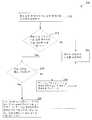
도 2는, 본 발명에 의한, 위상 인입을 회피하기 위해 충분한 주파수 간격을 제공하도록, 후보 신호와 기존 신호의 어느 하나 또는 모두를 재배치(relocating)하는 방법의 일 실시예를 도시한 도면이다.FIG. 2 is a diagram illustrating one embodiment of a method of relocating either or both of a candidate signal and an existing signal to provide sufficient frequency spacing to avoid phase pull in accordance with the present invention.
도 3은, 본 발명에 의한, 주파수 인입을 회피하기 위하여 기존 주파수 신호로부터 충분한 대역폭 간격을 제공하도록, 그 검출 윈도우(detection window) 내에 후보 신호가 재배치된 실시예의 일예를 도시한 도면이다.FIG. 3 shows an example of an embodiment in which the candidate signal is rearranged within a detection window to provide a sufficient bandwidth interval from an existing frequency signal in order to avoid frequency ingress according to the present invention.
명확성을 확보하기 위하여, 이전에 식별되었던 항목들은 이후의 도면에서도 동일한 참조 기호를 유지하도록 하였다.In order to ensure clarity, previously identified items are to be kept with the same reference signs in later drawings.
도 1A는, 본 발명에 의한, 동시에 동작 가능한 주파수 공급원들을 채용한 동조 가능한 시스템의 일 실시예를 도시한 도면이다. 도시된 바와 같이, 상기 동조 가능한 시스템 100은, 세 개의 주파수 공급원 FS1 120, FS2 130 및 FS3 140을 포함하며, 이들 중 적어도 하나(예를 들어, FS1 120)는 동조 가능하다. 다른 주파수 공 급원은, 시스템의 설계에 의하여 요구되거나 요청되는 바에 따라, 고정된 주파수 또는 동조 가능한 주파수를 생성하도록 동작할 수 있다.1A illustrates one embodiment of a tunable system employing simultaneously operable frequency sources in accordance with the present invention. As shown, the
도 1B는, 본 발명에 의한 동조 가능한 주파수 공급원의 일 실시예를 도시한 도면으로서, 본 실시예에서는 시그마-델타 (sigma-delta) 위상 동기 루프(phase locked loop; PLL)로서 구현된다. 상기 PLL은 쌍극성-상보성 금속 산화물 반도체(bipolar complementary metal oxide semiconductor; Bi-CMOS) 프로세스에 의하여 모놀리식형(monolithic)으로 제조될 수도 있으나, 본 발명의 기술 분야에서 통상의 지식을 가진 자라면, 모놀리식, 하이브리드(hybrid) 또는 개별 소자 형태로 다른 프로세스 또는 다른 물질(예컨대, CMOS, SiGe, GaAs)을 사용하여 상기 회로를 제작할 수도 있음을 이미 잘 알고 있을 것이다.FIG. 1B shows an embodiment of a tunable frequency source according to the present invention, which is embodied as a sigma-delta phase locked loop (PLL) in this embodiment. The PLL may be manufactured monolithic by a bipolar complementary metal oxide semiconductor (Bi-CMOS) process, but those skilled in the art will appreciate that It will be appreciated that the circuit may also be fabricated using other processes or other materials (eg CMOS, SiGe, GaAs) in the form of monolithic, hybrid or discrete devices.
도시된 바와 같이, 상기 주파수 공급원 100은 위상-주파수 검출기(phase-frequency detector) 121, 전하 펌프 회로(charge pump circuit) 122, 루프 필터(loop filter) 123, 선택 가능 전압 제어 발진기들(selectable VCOs)의 뱅크(bank)로서 도시된 동조 소스(tuning source) 124, 주 N 분할 카운터(main divide-by-N counter) 125, 및 프로그램 가능 시그마-델타 모듈레이터(programmable sigma-delta modulator) 126을 포함한다. 상기 시스마-델타 모듈레이터 126은 주파수 설정 제어 신호(frequency setting control signal) CNTL를 수신하며, 그에 응답하여, 요청된 분할 비율(divide ratio)에 도달하도록 상기 N 분할 카운터 125에 스케일링 제어 데이터 신호(scaling control data signal)를 공급한다. 상기 시그마-델타 모듈레이터 126은 또한 N 분할 신호(divide-by-N signal)(FDiv)를 클록 신호로서 수신하여, 그의 동작을 상기 N 분할 카운터 125와 동기시킨다.As shown, the
상기 동조 가능 주파수 공급원 FS1 120이 위상 동기 루프로서 도시되었으나, 다른 동조 가능 주파수 공급원, 예컨대 가변 발진기, 디지털 제어 발진기 등과 같은 것들도 대안으로서 채용될 수 있다. 고정 주파수 공급원은 L-C 공진 회로, 유전체 공진기(dielectric resonator), 수정 발진기 등과 같은 것으로 구현될 수 있다. 상기한 예들은 단순히 예시적인 것일 뿐이며, 본 발명의 기술 분야에서 통상의 지식을 가진 자라면, 동조 가능 또는 고정 주파수 공급원으로서 다른 것들이 본 발명의 다른 실시예에서 사용될 수 있다는 것을 잘 알고 있을 것이다.Although the tunable frequency source FS1 120 is shown as a phase locked loop, other tunable frequency sources, such as variable oscillators, digitally controlled oscillators and the like, may alternatively be employed. The fixed frequency source may be implemented with an LC resonant circuit, a dielectric resonator, a crystal oscillator, or the like. The above examples are merely exemplary, and one of ordinary skill in the art will appreciate that others as tunable or fixed frequency sources may be used in other embodiments of the present invention.
도 2는, 본 발명에 의한, 위상 인입 효과를 회피하기 위해 충분한 주파수 간격을 제공하도록, 후보 신호와 기존 신호의 어느 하나 또는 모두를 재배치(relocating)하는 방법의 일 실시예를 도시한 도면이다. 상기 프로세스는, 후보 신호(prospective signal)가 기존 신호(existing signal)의 주파수에 근접한 주파수를 갖도록 요청되는 단계 212에서 시작된다. 단계 214에서, 상기 후보 신호의 주파수가, 상기 기존 신호의 주파수의 인입 대역폭(pulling bandwidth) 내에 속하는지의 여부에 관하여 판단된다. 이 동작의 한 예시적 실시예에 의하면, 가장 근접한 기존 신호의 주파수 위치를 결정하기 위하여, 본 출원과 함께 출원된 "다중 주파수 공급원 시스템 및 그 동작 방법"이라는 명칭의 출원에 첨부된 도 3C에 도시된 바와 같은 데이터베이스 구조에 억세스하고, 그에 기초하여 상기 후보 신호의 주파수가 상기 기존 신호의 주파수의 인입 대역폭 내에 속하는지의 여부에 관하여 판단할 수 있다.FIG. 2 is a diagram illustrating one embodiment of a method of relocating either or both of a candidate signal and an existing signal to provide sufficient frequency spacing to avoid phase ingress effects according to the present invention. The process begins at
여기에서, 상기 "인입 대역폭(pulling bandwidth)"라는 용어는, 두 번째 신호의 존재로 인하여 대상 신호(subject signal)가 "인입"되거나 변조되어 대상 신호가 미리 정의된 위상 잡음 수준(phase noise level)을 초과하게 되는 한계 대역폭(threshold bandwidth)을 의미한다. 대상 신호의 인입 대역폭은 요망 위상 잡음 수준과 여타 요인들에 의하여 결정된다. 예를 들어, 상대적으로 높은 양호도(quality factor; Q)를 보이는 주파수 공급원은 주어진 위상 잡은 요건에 대해 상대적으로 좁은 인입 대역폭을 가질 것이다. 유사하게, 근접한 신호를 생성하는 주파수 공급원으로부터 멀리 격리된 주파수 공급원은, 동일한 위상 잡음 요건에 대하여 상대적으로 좁은 인입 대역폭을 가질 것이다. 주파수 공급원의 Q는 그 구성과 구조에 의존한다. 예를 들어, 고정된 주파수의 수정 또는 유전체 공진 발진기는 동조 가능한 발진기보다 더 높은 Q를 보일 것이다. (다른 주파수 공급원으로부터의) 주파수 공급원의 격리(isolation)도 또한 다중 공급원 시스템의 구성과 구조에 의존할 것이다. 극단의 경우, 즉 무한대의 Q를 보이는 주파수 공급원이나 근접한 신호를 생성하는 주파수 공급원으로부터 무한히 멀리 격리된 경우 등에는, 물론 이러한 상태가 하나의 집적 회로 상에 복수의 동조 가능한 공급원들이 구현된 본 발명의 특정 실시예의 경우에는 특히 불가능하겠지만, 0 Hz의 인입 대역폭을 가질 것이다. 따라서, 미리 정의된 인입 대역폭을 정의하기 위하여 특정의 동작 한계(operating threshold)가 선택된다. 예시적인 실시예에 의하면, 임의의 신호의 인입 대역폭은, 500 kHz보다 더 넓은 대역폭, 즉 600 kHz, 700 kHz, 800 kHz, 900 kHz, 1 MHz 또는 그 이상 넓은 대역폭 등과 같은 대역폭은 물론, 500 kHz보다 좁은 대역폭, 즉 250 kHz, 100 kHz, 50 kHz 또는 그 이하의 대역폭 등과 같은 대역폭들을 포함한다.Herein, the term "pulling bandwidth" means that the target signal is "retracted" or modulated due to the presence of the second signal so that the target signal has a predefined phase noise level. It means a threshold bandwidth that exceeds. The incoming bandwidth of the target signal is determined by the desired phase noise level and other factors. For example, a frequency source that exhibits a relatively high quality factor (Q) will have a relatively narrow incoming bandwidth for a given phased requirement. Similarly, frequency sources that are isolated from frequency sources that produce adjacent signals will have relatively narrow incoming bandwidth for the same phase noise requirements. The Q of the frequency source depends on its configuration and structure. For example, a fixed frequency crystal or dielectric resonator oscillator will show a higher Q than a tunable oscillator. Isolation of frequency sources (from other frequency sources) will also depend on the configuration and structure of the multiple source system. In extreme cases, i.e., infinitely isolated from a frequency source that exhibits infinite Q or a frequency source that generates an adjacent signal, of course, this is the case in which multiple tunable sources are implemented on one integrated circuit. It will be particularly impossible for certain embodiments, but will have an incoming bandwidth of 0 Hz. Thus, a specific operating threshold is selected to define a predefined incoming bandwidth. According to an exemplary embodiment, the incoming bandwidth of any signal is 500 kHz, as well as a bandwidth greater than 500 kHz, such as 600 kHz, 700 kHz, 800 kHz, 900 kHz, 1 MHz or more wide bandwidth, and the like. Narrower bandwidths, such as bandwidths of 250 kHz, 100 kHz, 50 kHz or less, and the like.
일 예로서, 시스템이 특정 주파수 오프셋에서 -45 dBc의 스퍼 수준(spur level)을 수용할 수 있다고 판단되었다면, 상기 시스템에 의하여 규정된 오프셋에서의 바람직한 한계(LO 정밀도)를 성취하기 위하여, (연산, 실험, 또는 설계 시뮬레이션에 의하여) 상기 주파수 공급원의 격리 및 Q를 선택할 수 있다. 예를 들어, 상기 LO 정확도가 ±1 MHz로 규정되고, 상기 시스템은 기존 신호의 주파수로부터 500 kHz의 오프셋에서 -45 dBc로 스퍼(spur)를 주도록 규격이 설정되었다면, 상기 인입 대역폭은 ±500 kHz이며, 상기 규정된 LO 정확도는 상기 LO로 하여금 상기 스퍼 수준에 약간의 여유를 확보하기 위하여 기존의 것으로부터 500 kHz의 이상 멀리 위치하도록 허용한다.As an example, if it is determined that the system can accept a spur level of -45 dBc at a particular frequency offset, to achieve the desired limit (LO precision) at the offset defined by the system, the , Experiment, or design simulation) may select the isolation and Q of the frequency source. For example, if the LO accuracy is specified to ± 1 MHz and the system is set to give spurs at -45 dBc at an offset of 500 kHz from the frequency of the existing signal, the incoming bandwidth is ± 500 kHz. The defined LO accuracy allows the LO to be located more than 500 kHz away from the existing one in order to make some room at the spur level.
단계 214에서, 만약 상기 후보 신호의 주파수가 상기 기존 신호의 주파수의 인입 대역폭 내에 속한다고 판단되었다면, 단계 216에서 상기 기존 신호를 생성하는 주파수 공급원이 동조 가능한 것인지에 관하여 판단한다. 만약 상기 기존 신호의 주파수 공급원이 (상기 공급원이 고정 주파수 공급원이거나, 동조 가능한 것이라고 해도 그 동조 범위의 최대 또는 최소 지점에서 이미 동조되어 있는 등의 이유로) 동조 가능한 것이 아니라면, 상기 프로세스는 단계 218로 진행하여, 상기 후보 신호 주파수는 상기 식별된 인입 대역폭 바깥의 새로운 후보 주파수 지점으로 동조 된다. 이러한 프로세스는, 예를 들어, 상기 인입 대역폭 바깥의 주파수 지점이 식별되고 상기 후보 주파수가 그곳으로 동조되는 단일 동작(single operation)으로서 수행될 수 있다. 상기 새로운 후보 주파수 지점은, 예를 들어, 상기 인입 대역폭 바깥에서, 원래 요청됐던 후보 주파수 지점으로부터 가장 조금 이동된 주파수 지점일 수 있다. 또는, 상기 216 단계의 동작은 둘 또는 그 이상의 동조 동작을 포함할 수 있는데, 즉 상기 주파수 공급원은 제1 주파수 지점으로 동조되고, 선택적으로 상기 제1 주파수 지점이 상기 기존 신호의 인입 대역폭 바깥에 존재하는지를 판단하여, 만약 그렇지 않다면 제2의 더 이동된 주파수 지점을 식별하여 상기 주파수 공급원을 그 지점으로 동조시키는 동작들이다. 이러한 방식으로, 상기 후보 신호는, 상기 기존 신호로부터 필요한 대역폭만큼 간격이 벌어질 때까지 (상기 시스템에 의하여 규정된 상기 LO 정확도에 따라), 점진적으로 기존 신호로부터 멀어진다. 본 발명의 기술 분야에서 통상의 지식을 가진 자라면, 상기 후보 신호를 상기 인입 대역폭으로부터 벗어나도록 재배치하기 위한 다른 기술들이 사용될 수 있음을 이미 잘 알고 있을 것이다. 이어서, 단계 222에서, 새로운 후보 주파수 지점에서 상기 후보 신호가 생성된다.In
단계 216에서, 만약 상기 기존 신호가 그의 현재 범위 내에서 동조될 수 있다면, 상기 프로세스는 단계 220으로 진행하여, 상기 후보 신호의 주파수 지점은 다음의 세 가지 동작중 어느 하나에 의하여 상기 인입 대역폭 내로부터 이동한다. 즉, (i) 상기 후보 신호의 주파수가, 상기 기존 신호의 주파수로부터 떨어진, 인입 대역폭 바깥의 새로운 후보 신호 주파수로 동조되거나, (ii) 상기 기존 신호의 주 파수가, 현재의 주파수 지점으로부터 벗어나, 상기 후보 신호로부터도 떨어진 새로운 기존 신호 주파수 지점으로 동조되거나, 또는 (iii) 상기 (i)과 (ii)의 조합으로서, 상기 후보 및 기존 신호의 주파수들이 모두 각각의 새로운 주파수 지점을 향해 반대 방향으로 동조되는데, 그 새로운 후보 주파수 지점이 그 새로운 기존 주파수 지점의 인입 대역폭 바깥에 위치하도록 각 신호가 새로운 주파수 지점으로 이동한다. (i) 내지 (iii)의 동작 중 단계 220에서 선택되는 특정의 동작은, 그 공급원의 동조 능력에 따라 결정된다. 예를 들어, 동작 (i)은, 기존 신호의 주파수 공급원이 그 주파수 극단에 위치하여 상기 후보 신호로부터 더 이상 멀어질 수 없는 경우이거나, 상기 기존 신호가 방해되어서는 안되는 동작에 사용되거나 그 동작을 수행중인 경우에 채용될 수 있다. 동작 (ii)는, 상기 후보 신호가 상기 기존 신호로부터 더 이상 멀리 동조될 수 없다는 연산 결과가 제시되었을 때 활용될 수 있다. 동작 (iii)은, 두 주파수 공급원이 모두 충분한 동조 범위를 가지고 있으며, 또한, 요구되는 주파수 이격을 획득하기 위하여, 각 신호의 원래 동조 지점으로부터의 필요한 주파수 오프셋을 최소화하기 위하여 채용될 수 있다. 본 발명의 특정 실시예에 의하면, 이하에서 도 3을 참조하여 설명되는 바와 같이, 상기 후보 및 기존 신호의 모두 또는 어느 하나는, 서로 교차하지 않는 방식으로 상대로부터 멀어져서 동조된다.In
단계 216에서의 동작과 유사하게, 단계 222에서의 동작들도 단일 동작 또는 복수의 동작들에 의하여 수행될 수 있다. 전자에 대한 예시적 실시예에는, 예를 들면, 상기 후보 신호의 주파수를 상기 인입 대역폭의 바깥에 위치하도록 하기 위 하여 필요한 대역폭 간격을 제공하는 새로운 주파수 지점을 연산하여, 상기 후보 및 기존 주파수들이 그 각각의 주파수 지점에서 생성되도록 하는 것이 포함된다. 또는, 후자의 접근 방법에서는, 반복적 프로세스가 수행되는데, 하나 또는 양쪽 신호들이 점차 서로 멀어지며, 선택적으로 상기 인입 대역폭 바깥에 상기 후보 신호가 위치하도록 하기에 필요한 대역폭 간격이 확보되었는지를 판단하기 위하여 양자간 대역폭 간격을 점검한다. 상기 기존 주파수 신호가 동조되는 실시예에 의하면, 그 주파수 공급원이 계속 상기 기존 신호를 생성해 가면서 그 원래 주파수 지점으로부터 벗어나서 동조되거나, 또는 상기 기존 신호를 비활성화시키고, 상기 주파수 공급원이 다음의 기존 주파수 지점으로 동조되도록 구성되고, 그 새로운 주파수 지점에서 기존 신호를 생성하는 어느 한 방식으로 동작한다. 지속적으로 기존 신호가 동작하는 점진적 동조 접근 방법은, 대대적인 동조 단계를 동반할 수 있는 커다란 주파수 오버슈트(overshoot) 효과의 발생을 피할 수 있다는 점에서 이점이 있다.Similar to the operation in
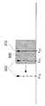
도 3은, 본 발명에 따라, 주파수 인입을 회피하기 위하여 기존 주파수 신호로부터 충분한 대역폭 간격을 제공하도록, 후보 신호가 재배치된 본 발명의 실시예의 일예를 도시한 도면이다. 기존 신호 312는 주파수 지점 FE1에서 동작하며, 상기 기존 신호의 주파수는 그에 연관된 미리 정의된 인입 대역폭 320을 갖는다. 이어서, 제1 후보 주파수 지점 FP1으로 후보 신호 322를 동조시키라는 요청이 수신되는데, 상기 제1 후보 주파수 지점 FP1은 상기 기존 주파수의 인입 대역폭 320 내에 속 한다. 상기한 바와 같이, 상기 인입 대역폭은, 일반적으로 주파수 공급원의 양호도(Q), 및 그 주파수 공급원과 상기 근접 신호를 생성하는 주파수 공급원 사이의 격리(isolation) 등에 의존할 것이다. 본 발명의 일 실시예에 의하면, 모든 주파수 공급원은 실질적으로 동일한 양호도(Q) 및 격리를 보이며, 따라서 각 주파수 공급원은 실질적으로 동일한 인입 대역폭을 가질 것이다. 본 발명의 다른 실시예에 의하면, 하나 또는 그 이상의 주파수 공급원에 대하여 상기 양호도(Q) 및 격리가 다르며, 따라서 상기 인입 대역폭은 일단 상기 동조되는 (제2) 주파수 공급원이 식별된 후에 결정될 것이다.3 illustrates an example of an embodiment of the present invention in which candidate signals are rearranged to provide sufficient bandwidth spacing from existing frequency signals in order to avoid frequency ingress in accordance with the present invention. The existing
상기 제1 후보 주파수 지점 FP1으로의 동조 요청을 받으면, 신호의 생성이나 그리로의 동조 이전에, 상기 FP1이 상기 기존 신호 312의 인입 대역폭 320 내에 속하는지의 여부에 대하여 판단한다(단계 214). 도시된 실시예에서는, FP1이 상기 인입 대역폭 320 내에 위치하며, 상기한 프로세스는 단계 216으로 진행하여, 상기 기존 신호 312가 동조 가능한 주파수 공급원에 의하여 생성되는지의 여부에 대하여 판단한다. 예시를 위하여, 본 실시예에서는, 상기 기존 신호 312가 고정 주파수 공급원에 의하여 생성되는 것으로 판단되었다. 그러한 경우에는, 동조 프로세스가 단계 218로 진행하여, 상기 후보 신호가 상기 제1 주파수 지점 FP1으로부터 교차하지 않는 방식으로 멀어져 제2 후보 주파수 지점 FP2로 재배치된다. 단계 218에서의 동조 동작은, 상기 FP2가 상기 기존 신호 312의 인입 대역폭 320의 바깥에 위치하는지의 여부에 대하여 판단하는 단계를 더 포함할 수 있다. 상기 프로세스는 단계 222로 진행하여, 상기 후보 신호 322가 상기 제2 후보 주파수 지점 FP2에서 생성된다. 또는, 상기 단계 218에서, 상기 프로세스는 반복적으로 수행되어, 상기 후보 신호가 하나 또는 그 이상의 단계를 거쳐 상기 기존 신호의 주파수로부터 점진적으로 멀어질 수 있다.Upon receiving a request for tuning to the first candidate frequency point FP1 , it is determined whether FP1 falls within the
상기 기존 주파수 공급원이 동조 가능한 다른 실시예에서는, 상기 기존 신호 312를 FE1보다 약간 위쪽으로 재배치하고 (그에 따라 상기 인입 대역폭 320도 주파수가 약간 더 높아지도록 함께 이동하며), 상기 후보 신호 322를 FP1보다 약간 아래쪽으로 재배치하는 것의 결합 효과로 인하여, 상대적으로 더 작은 주파수만큼 이동하면서도 필요한 대역폭 간격을 성취할 수 있으므로, 각 주파수의 재배치 거리가 더 적게 된다. 상기 시스템의 예시적 실시예에 의하면, 시그마-델타 위상 동조 루프와 같은 동조 가능한 시스템이 상기 기존 및 후보 신호를 생성하는 주파수 공급원으로서 사용될 수 있다. 또 다른 실시예에 의하면, 신호를 그의 최종 주파수로 재배치하는 데에 동반될 수 있는 주파수 오버슈트 효과를 감소시키기 위하여, 상기 기존 주파수를 상기 후보 주파수 신호로부터 멀어지도록 둘 또는 그 이상의 단계를 거쳐 반복적으로 동조시킨다.In another embodiment where the existing frequency source can be tuned, the existing
상기 후보 신호와 기존 신호의 어느 하나 또는 모두가 재배치되는 본 발명의 실시예에 의하면, 상기 주파수 공급원은 새로운 주파수 지점으로 신호를 재배치하는 동안 그 신호의 생성을 지속할 수 있음을 주의하여야 한다. 또는, 상기 주파수 공급원은 비활성화되고, 새로운 주파수(예컨대 더 높은 주파수)로 동조되도록 구성 되고, 그 새로운 주파수 지점에서 그의 신호를 활성화할 수도 있다.It should be noted that in accordance with an embodiment of the present invention in which either or both of the candidate signal and the existing signal are relocated, the frequency source may continue to generate the signal while relocating the signal to a new frequency point. Alternatively, the frequency source may be deactivated, configured to tune to a new frequency (eg, a higher frequency), and activate its signal at that new frequency point.
본 발명의 기술 분야에서 통상의 지식을 가진 자라면 이미 잘 알고 있듯이, 상기한 프로세스들은 하드웨어, 소프트웨어, 펌웨어(firmware) 또는 필요에 따라 이들의 조합에 의하여 구현될 수 있다. 또한, 상기한 모든 또는 일부의 프로세스들은, 컴퓨터로 판독 가능한 매체(착탈 가능 디스크, 휘발성 또는 비휘발성 메모리, 내장 프로세서(embeded processor), 등) 상에 기록된 컴퓨터로 판독 가능한 명령 코드(instruction code)로서 구현될 수 있으며, 상기 명령 코드들은 상기한 기능들을 수행하도록 기타 프로그램 가능한 장치들의 컴퓨터를 프로그램하도록 동작할 수 있다.As those skilled in the art will already know, the above processes may be implemented by hardware, software, firmware, or a combination thereof as needed. In addition, all or some of the processes described above may be computer readable instruction code recorded on a computer readable medium (removable disk, volatile or nonvolatile memory, embedded processor, etc.). And the command codes may be operable to program a computer of other programmable devices to perform the functions described above.
여기서, "하나"라는 용어는 하나 또는 하나 이상의 기술된 특성을 지칭하기 위하여 사용되었다. 또한, "결합" 또는 "접속"이라는 용어는, 직접 상호간에 또는 중간에 하나 또는 그 이상의 구조물이나 물체를 경유하여 서로 (경우에 따라, 전기적, 기계적, 열적 등으로) 통신하는 특성을 지칭한다. 방법의 흐름도에 도시된 동작이나 행동들의 순서는 예시적인 것일 뿐이며, 이 동작들 및 행동들은 다른 순서로 수행되거나, 이들 중 둘 또는 그 이상의 것들은 동시에 수행될 수도 있다. 여기에서 언급된 모든 간행물, 특허 및 기타 문서들은 그 전체를 참조에 의하여 편입시킨다. 상기 편입된 문서들과 본 명세서 사이에 불일치가 있는 경우에는 본 명세서가 우선한다.Here, the term "one" is used to refer to one or more of the described features. In addition, the terms “coupled” or “connected” refer to the property of communicating with one another (or optionally, electrically, mechanically, thermally, etc.) via one or more structures or objects directly or in between each other. The order of the actions or actions shown in the flowchart of the method is illustrative only and the actions and actions may be performed in a different order, or two or more of them may be performed simultaneously. All publications, patents, and other documents mentioned herein are incorporated by reference in their entirety. In case of any inconsistency between the incorporated documents and this specification, this specification takes precedence.
상기한 설명은 예시와 설명의 목적으로 개시된 것이다. 본 발명을 그 개시된 형태로 한정시키거나 제한하려는 의도는 없으며, 명백히 다양한 수정과 변경이 본 발명의 조망하에 가능하다. 개시된 실시예들은 본 발명의 원리와 그의 현실적 응용을 설명하기에 가장 적합하도록 선택되었으며, 그리하여 본 발명의 기술 분야에서 통상의 지식을 가진 자들에게, 생각할 수 있는 특정의 용도에 적합하도록 본 발명의 다양한 실시예들과 다양한 수정들을 통해 본 발명을 활용할 수 있도록 한다. 본 발명의 권리 범위는 이하의 특허청구범위에 의하여 정의되어야 한다.The foregoing description has been disclosed for purposes of illustration and description. It is not intended to be exhaustive or to limit the invention to the precise form disclosed, and obviously, numerous modifications and variations are possible in view of the invention. The disclosed embodiments have been chosen to be best suited to explain the principles of the present invention and its practical application, and accordingly various modifications of the present invention to those skilled in the art to suit the particular use conceivable. Embodiments and various modifications may be utilized to utilize the present invention. The scope of the invention should be defined by the following claims.
동시에 동작할 수 있는 주파수 공급원들을 채용한 시스템에서 위상 인입을 완화하기 위한 시스템 및 방법이 제시된다.A system and method are disclosed for mitigating phase in in a system employing frequency sources capable of operating simultaneously.
Claims (20)
Translated fromKoreanApplications Claiming Priority (6)
| Application Number | Priority Date | Filing Date | Title |
|---|---|---|---|
| US59575005P | 2005-08-02 | 2005-08-02 | |
| US59575405P | 2005-08-02 | 2005-08-02 | |
| US59574905P | 2005-08-02 | 2005-08-02 | |
| US60/595,754 | 2005-08-02 | ||
| US60/595,749 | 2005-08-02 | ||
| US60/595,750 | 2005-08-02 |
Publications (2)
| Publication Number | Publication Date |
|---|---|
| KR20080023760A KR20080023760A (en) | 2008-03-14 |
| KR100853047B1true KR100853047B1 (en) | 2008-08-19 |
Family
ID=37467507
Family Applications (4)
| Application Number | Title | Priority Date | Filing Date |
|---|---|---|---|
| KR1020087002866AExpired - Fee RelatedKR100853047B1 (en) | 2005-08-02 | 2006-08-01 | Phase Entry Mitigation System and Method in Multi-frequency Source Systems |
| KR1020097009988AExpired - Fee RelatedKR100966926B1 (en) | 2005-08-02 | 2006-08-01 | Multi-frequency source system and its operation method |
| KR1020087003990AExpired - Fee RelatedKR100917085B1 (en) | 2005-08-02 | 2006-08-01 | Multiple Frequency Source System and Method of Operation |
| KR1020087005222AExpired - Fee RelatedKR100967723B1 (en) | 2005-08-02 | 2006-08-01 | Offset Signal Phase Processing for Multi-Frequency Source Systems |
Family Applications After (3)
| Application Number | Title | Priority Date | Filing Date |
|---|---|---|---|
| KR1020097009988AExpired - Fee RelatedKR100966926B1 (en) | 2005-08-02 | 2006-08-01 | Multi-frequency source system and its operation method |
| KR1020087003990AExpired - Fee RelatedKR100917085B1 (en) | 2005-08-02 | 2006-08-01 | Multiple Frequency Source System and Method of Operation |
| KR1020087005222AExpired - Fee RelatedKR100967723B1 (en) | 2005-08-02 | 2006-08-01 | Offset Signal Phase Processing for Multi-Frequency Source Systems |
Country Status (6)
| Country | Link |
|---|---|
| US (3) | US7355483B2 (en) |
| EP (3) | EP1910908A1 (en) |
| JP (3) | JP2009504064A (en) |
| KR (4) | KR100853047B1 (en) |
| AT (1) | ATE535065T1 (en) |
| WO (3) | WO2007015210A1 (en) |
Families Citing this family (19)
| Publication number | Priority date | Publication date | Assignee | Title |
|---|---|---|---|---|
| US7783467B2 (en)* | 2005-12-10 | 2010-08-24 | Electronics And Telecommunications Research Institute | Method for digital system modeling by using higher software simulator |
| US7474167B1 (en)* | 2006-08-31 | 2009-01-06 | Altera Corporation | Capacitance switch circuitry for digitally controlled oscillators |
| US7869781B2 (en) | 2006-12-06 | 2011-01-11 | Broadcom Corporation | Method and system for mitigating the effects of pulling in multiple phase locked loops in multi-standard systems |
| US20080143192A1 (en)* | 2006-12-14 | 2008-06-19 | Sample Alanson P | Dynamic radio frequency power harvesting |
| CN101197573B (en)* | 2007-01-10 | 2010-12-29 | 晨星半导体股份有限公司 | Clock generator and self-testing and switching control method applied to same |
| JP2009010599A (en)* | 2007-06-27 | 2009-01-15 | Panasonic Corp | Digitally controlled oscillator circuit, frequency synthesizer, wireless communication device using the same, and control method therefor |
| US8212610B2 (en)* | 2008-09-19 | 2012-07-03 | Altera Corporation | Techniques for digital loop filters |
| KR101467417B1 (en)* | 2008-12-30 | 2014-12-11 | 주식회사 동부하이텍 | Digital synchronous circuit |
| US20100250746A1 (en)* | 2009-03-30 | 2010-09-30 | Hitachi, Ltd. | Information technology source migration |
| JP5148548B2 (en)* | 2009-04-17 | 2013-02-20 | 株式会社東芝 | Digital PLL circuit and semiconductor integrated circuit |
| JP5367075B2 (en) | 2009-05-22 | 2013-12-11 | パナソニック株式会社 | PLL frequency synthesizer |
| US8756451B2 (en)* | 2011-10-01 | 2014-06-17 | Intel Corporation | Frequency synthesis methods and systems |
| US8692594B2 (en)* | 2011-12-19 | 2014-04-08 | Ati Technologies Ulc | Phase-locked loop frequency stepping |
| US9166604B2 (en)* | 2012-04-25 | 2015-10-20 | Infineon Technologies Ag | Timing monitor for PLL |
| US9490825B2 (en)* | 2013-05-23 | 2016-11-08 | Intel IP Corporation | Adjusting tuning segments in a digitally-controlled oscillator |
| US9509353B2 (en) | 2014-08-20 | 2016-11-29 | Nxp B.V. | Data processing device |
| GB201800174D0 (en)* | 2018-01-05 | 2018-02-21 | Kirintec Ltd | Receiver |
| CN111508416B (en)* | 2020-04-30 | 2021-09-03 | 武汉华星光电半导体显示技术有限公司 | Display and driving method thereof |
| CN115015870A (en)* | 2022-05-27 | 2022-09-06 | 中国电子科技集团公司第十四研究所 | Method for synchronizing signal phases among multiple frequency sources |
Citations (1)
| Publication number | Priority date | Publication date | Assignee | Title |
|---|---|---|---|---|
| JP2001332969A (en)* | 2000-05-23 | 2001-11-30 | Nec Microsystems Ltd | Oscillator |
Family Cites Families (38)
| Publication number | Priority date | Publication date | Assignee | Title |
|---|---|---|---|---|
| JPS6120420A (en)* | 1984-07-06 | 1986-01-29 | Nec Corp | Polyphase clock generating circuit |
| JP2541313B2 (en)* | 1989-07-29 | 1996-10-09 | 日本電気株式会社 | Dual PLL device |
| US5452290A (en) | 1992-10-26 | 1995-09-19 | Motorola, Inc. | Look ahead channel switching transceiver |
| US5408196A (en) | 1993-03-29 | 1995-04-18 | U.S. Philips Corporation | Tunable device |
| US6334219B1 (en) | 1994-09-26 | 2001-12-25 | Adc Telecommunications Inc. | Channel selection for a hybrid fiber coax network |
| US7339078B2 (en)* | 1995-03-10 | 2008-03-04 | G.D. Searle Llc | Bis-amino acid hydroxyethylamino sulfonamide retroviral protease inhibitors |
| US6177964B1 (en)* | 1997-08-01 | 2001-01-23 | Microtune, Inc. | Broadband integrated television tuner |
| JP3453006B2 (en)* | 1995-07-07 | 2003-10-06 | パイオニア株式会社 | Phase synchronization circuit and digital signal reproducing device |
| US5774701A (en)* | 1995-07-10 | 1998-06-30 | Hitachi, Ltd. | Microprocessor operating at high and low clok frequencies |
| US5565816A (en) | 1995-08-18 | 1996-10-15 | International Business Machines Corporation | Clock distribution network |
| JPH09246967A (en)* | 1996-03-04 | 1997-09-19 | Casio Comput Co Ltd | PLL frequency synthesizer circuit |
| JP3323054B2 (en)* | 1996-04-01 | 2002-09-09 | 株式会社東芝 | Frequency multiplier |
| JP3596172B2 (en)* | 1996-06-19 | 2004-12-02 | 富士通株式会社 | PLL frequency synthesizer |
| JPH10270999A (en)* | 1997-03-24 | 1998-10-09 | Seiko Epson Corp | Semiconductor device |
| JP3279957B2 (en)* | 1997-05-23 | 2002-04-30 | 松下電器産業株式会社 | Portable wireless devices |
| JPH11205101A (en)* | 1998-01-13 | 1999-07-30 | Toshiba Corp | Phase tracking device |
| US6112308A (en)* | 1998-01-23 | 2000-08-29 | Intel Corporation | Cascaded multiple internal phase-locked loops for synchronization of hierarchically distinct chipset components and subsystems |
| SE513950C2 (en)* | 1998-02-12 | 2000-12-04 | Ericsson Telefon Ab L M | Method and apparatus of a mobile telecommunication network to provide a multi-channel connection |
| US6628779B1 (en) | 1998-05-11 | 2003-09-30 | Telcordia Technologies, Inc. | Method and system for scaleable near-end speech cancellation for tip and ring tone signal detectors |
| US6304146B1 (en) | 1998-05-29 | 2001-10-16 | Silicon Laboratories, Inc. | Method and apparatus for synthesizing dual band high-frequency signals for wireless communications |
| JP2000286704A (en)* | 1999-01-28 | 2000-10-13 | Matsushita Electric Ind Co Ltd | Frequency synthesizer device and mobile radio using the same |
| JP2000341748A (en)* | 1999-04-15 | 2000-12-08 | Texas Instr Inc <Ti> | Method for allocating transmission resource in wireless communication system, frequency channel and time slot allocation system |
| US6147561A (en)* | 1999-07-29 | 2000-11-14 | Conexant Systems, Inc. | Phase/frequency detector with time-delayed inputs in a charge pump based phase locked loop and a method for enhancing the phase locked loop gain |
| TW496035B (en)* | 2000-04-25 | 2002-07-21 | Univ Singapore | Method and apparatus for a digital clock multiplication circuit |
| US6686803B1 (en)* | 2000-07-10 | 2004-02-03 | Silicon Laboratories, Inc. | Integrated circuit incorporating circuitry for determining which of at least two possible frequencies is present on an externally provided reference signal and method therefor |
| JP4454810B2 (en)* | 2000-08-04 | 2010-04-21 | Necエレクトロニクス株式会社 | Digital phase control method and digital phase control circuit |
| DE10102725C2 (en)* | 2001-01-22 | 2003-04-24 | Infineon Technologies Ag | Method for operating a PLL frequency synthesis circuit |
| JP2003133950A (en)* | 2001-10-24 | 2003-05-09 | Nippon Dempa Kogyo Co Ltd | Input switching voltage controlled oscillator and PLL controlled oscillator |
| EP1318641A3 (en)* | 2001-12-10 | 2006-10-04 | Alps Electric Co., Ltd. | Carrier recovery with antenna diversity |
| US7062229B2 (en)* | 2002-03-06 | 2006-06-13 | Qualcomm Incorporated | Discrete amplitude calibration of oscillators in frequency synthesizers |
| US20030179842A1 (en)* | 2002-03-22 | 2003-09-25 | Kane Michael G. | Digital pattern sequence generator |
| JP2004072714A (en) | 2002-06-11 | 2004-03-04 | Rohm Co Ltd | Clock generating system |
| KR100465455B1 (en) | 2002-06-24 | 2005-01-13 | 씨제이 주식회사 | Thioxo thiazole derivatives, processes for the preparation thereof, and pharmaceutical compositions containing the same |
| US20040006850A1 (en) | 2002-07-09 | 2004-01-15 | Wax David B. | Personal pen retaining system |
| JP4164301B2 (en)* | 2002-07-16 | 2008-10-15 | 株式会社日立製作所 | Multi-frequency PLL oscillator and multi-frequency CW radar using the same |
| WO2004082277A1 (en)* | 2003-03-11 | 2004-09-23 | Thomson Licensing S.A. | Apparatus and method for distributing signals |
| US6954093B2 (en) | 2003-03-27 | 2005-10-11 | Micronas Gmbh | Clocking scheme and clock system for a monolithic integrated circuit |
| JP2006180398A (en)* | 2004-12-24 | 2006-07-06 | Toshiba Corp | Clock generation apparatus and clock generation method |
- 2006
- 2006-08-01JPJP2008524658Apatent/JP2009504064A/enactivePending
- 2006-08-01KRKR1020087002866Apatent/KR100853047B1/ennot_activeExpired - Fee Related
- 2006-08-01USUS11/461,534patent/US7355483B2/ennot_activeExpired - Fee Related
- 2006-08-01EPEP06766078Apatent/EP1910908A1/ennot_activeWithdrawn
- 2006-08-01USUS11/461,533patent/US7653370B2/ennot_activeExpired - Fee Related
- 2006-08-01KRKR1020097009988Apatent/KR100966926B1/ennot_activeExpired - Fee Related
- 2006-08-01EPEP06766077Apatent/EP1911159A1/ennot_activeWithdrawn
- 2006-08-01KRKR1020087003990Apatent/KR100917085B1/ennot_activeExpired - Fee Related
- 2006-08-01USUS11/461,530patent/US7528665B2/ennot_activeExpired - Fee Related
- 2006-08-01JPJP2008524657Apatent/JP4395541B2/ennot_activeExpired - Fee Related
- 2006-08-01WOPCT/IB2006/052633patent/WO2007015210A1/enactiveApplication Filing
- 2006-08-01ATAT06780271Tpatent/ATE535065T1/enactive
- 2006-08-01EPEP06780271Apatent/EP1911185B1/ennot_activeNot-in-force
- 2006-08-01KRKR1020087005222Apatent/KR100967723B1/ennot_activeExpired - Fee Related
- 2006-08-01WOPCT/IB2006/052634patent/WO2007015211A2/enactiveApplication Filing
- 2006-08-01JPJP2008524659Apatent/JP4245658B2/ennot_activeExpired - Fee Related
- 2006-08-01WOPCT/IB2006/052632patent/WO2007015209A1/enactiveApplication Filing
Patent Citations (1)
| Publication number | Priority date | Publication date | Assignee | Title |
|---|---|---|---|---|
| JP2001332969A (en)* | 2000-05-23 | 2001-11-30 | Nec Microsystems Ltd | Oscillator |
Also Published As
| Publication number | Publication date |
|---|---|
| US7355483B2 (en) | 2008-04-08 |
| US20070200640A1 (en) | 2007-08-30 |
| WO2007015210A1 (en) | 2007-02-08 |
| EP1911185B1 (en) | 2011-11-23 |
| JP4245658B2 (en) | 2009-03-25 |
| KR20080025766A (en) | 2008-03-21 |
| WO2007015211A3 (en) | 2007-04-19 |
| JP4395541B2 (en) | 2010-01-13 |
| US20070176663A1 (en) | 2007-08-02 |
| KR100917085B1 (en) | 2009-09-15 |
| US7653370B2 (en) | 2010-01-26 |
| KR100967723B1 (en) | 2010-07-05 |
| KR20080031503A (en) | 2008-04-08 |
| EP1911159A1 (en) | 2008-04-16 |
| KR20090058593A (en) | 2009-06-09 |
| KR20080023760A (en) | 2008-03-14 |
| EP1910908A1 (en) | 2008-04-16 |
| JP2009504063A (en) | 2009-01-29 |
| WO2007015209A1 (en) | 2007-02-08 |
| JP2009504064A (en) | 2009-01-29 |
| EP1911185A2 (en) | 2008-04-16 |
| KR100966926B1 (en) | 2010-06-29 |
| US20070183014A1 (en) | 2007-08-09 |
| ATE535065T1 (en) | 2011-12-15 |
| WO2007015211A2 (en) | 2007-02-08 |
| JP2009508369A (en) | 2009-02-26 |
| US7528665B2 (en) | 2009-05-05 |
Similar Documents
| Publication | Publication Date | Title |
|---|---|---|
| KR100853047B1 (en) | Phase Entry Mitigation System and Method in Multi-frequency Source Systems | |
| US10651858B2 (en) | Synthesizer and phase frequency detector | |
| US8791734B1 (en) | Cascaded PLL for reducing low-frequency drift in holdover mode | |
| US8456204B2 (en) | Phase-locked loop systems using adaptive low-pass filters in switched bandwidth feedback loops | |
| US10976409B2 (en) | Frequency-modulated continuous wave generator and frequency-modulated continuous wave radar system including the same | |
| US7538622B2 (en) | Multiple reference frequency fractional-N PLL (phase locked loop) | |
| US9312867B2 (en) | Phase lock loop device with correcting function of loop bandwidth and method thereof | |
| CN101179262A (en) | filter circuit device | |
| KR100894236B1 (en) | PLL circuit, method of preventing interference of the PLL circuit and optical-disk apparatus having the PLL circuit | |
| US8274337B2 (en) | Digital phase locked loop | |
| KR102335966B1 (en) | Multi vco apparatus using phase locked loop circuit for outputting multi-synchronizing signals | |
| KR20180131017A (en) | Frequency Synthesizer with Dual Paths for Wideband FMCW | |
| KR100817286B1 (en) | Phase locked loop and method for stably adjusting frequency band of voltage controlled oscillator | |
| EP3107213B1 (en) | Frequency synthesizer circuit with linearized gain of the controlled oscillator | |
| KR101710717B1 (en) | Frequency calibration method and apparatus with frequency synthesizer | |
| US7109763B1 (en) | Phase locked loop operable over a wide frequency range | |
| KR101327100B1 (en) | Frequency divider, phase locked loop circuit including the same and control method thereof | |
| JP2001230670A (en) | PLL oscillation circuit | |
| GB2567463A (en) | Phase locked loop circuit | |
| KR101823790B1 (en) | Phase Lock Loop by using Time-Matching of Up or Down Pulse | |
| KR20210026680A (en) | X-tal oscillator based hetero multi output oscillator apparatus | |
| WO2006036749A3 (en) | Apparatus and method of oscillating wideband frequency | |
| KR20000026476A (en) | Phase locked loop of semiconductor device | |
| EP0467449A2 (en) | Multiloop microwave frequency synthesizer with low phase noise | |
| KR101062311B1 (en) | Phased Array System |
Legal Events
| Date | Code | Title | Description |
|---|---|---|---|
| A201 | Request for examination | ||
| PA0105 | International application | St.27 status event code:A-0-1-A10-A15-nap-PA0105 | |
| PA0201 | Request for examination | St.27 status event code:A-1-2-D10-D11-exm-PA0201 | |
| A302 | Request for accelerated examination | ||
| PA0302 | Request for accelerated examination | St.27 status event code:A-1-2-D10-D17-exm-PA0302 St.27 status event code:A-1-2-D10-D16-exm-PA0302 | |
| P11-X000 | Amendment of application requested | St.27 status event code:A-2-2-P10-P11-nap-X000 | |
| P13-X000 | Application amended | St.27 status event code:A-2-2-P10-P13-nap-X000 | |
| PG1501 | Laying open of application | St.27 status event code:A-1-1-Q10-Q12-nap-PG1501 | |
| E701 | Decision to grant or registration of patent right | ||
| PE0701 | Decision of registration | St.27 status event code:A-1-2-D10-D22-exm-PE0701 | |
| GRNT | Written decision to grant | ||
| PR0701 | Registration of establishment | St.27 status event code:A-2-4-F10-F11-exm-PR0701 | |
| PR1002 | Payment of registration fee | St.27 status event code:A-2-2-U10-U12-oth-PR1002 Fee payment year number:1 | |
| PG1601 | Publication of registration | St.27 status event code:A-4-4-Q10-Q13-nap-PG1601 | |
| PR1001 | Payment of annual fee | St.27 status event code:A-4-4-U10-U11-oth-PR1001 Fee payment year number:4 | |
| FPAY | Annual fee payment | Payment date:20120725 Year of fee payment:5 | |
| PR1001 | Payment of annual fee | St.27 status event code:A-4-4-U10-U11-oth-PR1001 Fee payment year number:5 | |
| FPAY | Annual fee payment | Payment date:20130725 Year of fee payment:6 | |
| PR1001 | Payment of annual fee | St.27 status event code:A-4-4-U10-U11-oth-PR1001 Fee payment year number:6 | |
| PN2301 | Change of applicant | St.27 status event code:A-5-5-R10-R11-asn-PN2301 | |
| R18-X000 | Changes to party contact information recorded | St.27 status event code:A-5-5-R10-R18-oth-X000 | |
| PN2301 | Change of applicant | St.27 status event code:A-5-5-R10-R14-asn-PN2301 | |
| FPAY | Annual fee payment | Payment date:20140725 Year of fee payment:7 | |
| PR1001 | Payment of annual fee | St.27 status event code:A-4-4-U10-U11-oth-PR1001 Fee payment year number:7 | |
| LAPS | Lapse due to unpaid annual fee | ||
| PC1903 | Unpaid annual fee | St.27 status event code:A-4-4-U10-U13-oth-PC1903 Not in force date:20150813 Payment event data comment text:Termination Category : DEFAULT_OF_REGISTRATION_FEE | |
| PC1903 | Unpaid annual fee | St.27 status event code:N-4-6-H10-H13-oth-PC1903 Ip right cessation event data comment text:Termination Category : DEFAULT_OF_REGISTRATION_FEE Not in force date:20150813 |