KR100852360B1 - Personal portable device - Google Patents
Personal portable deviceDownload PDFInfo
- Publication number
- KR100852360B1 KR100852360B1KR1020060135422AKR20060135422AKR100852360B1KR 100852360 B1KR100852360 B1KR 100852360B1KR 1020060135422 AKR1020060135422 AKR 1020060135422AKR 20060135422 AKR20060135422 AKR 20060135422AKR 100852360 B1KR100852360 B1KR 100852360B1
- Authority
- KR
- South Korea
- Prior art keywords
- plate
- main body
- portable terminal
- personal portable
- decor
- Prior art date
- Legal status (The legal status is an assumption and is not a legal conclusion. Google has not performed a legal analysis and makes no representation as to the accuracy of the status listed.)
- Expired - Fee Related
Links
Images


Classifications
- H—ELECTRICITY
- H04—ELECTRIC COMMUNICATION TECHNIQUE
- H04M—TELEPHONIC COMMUNICATION
- H04M1/00—Substation equipment, e.g. for use by subscribers
- H04M1/02—Constructional features of telephone sets
- H04M1/23—Construction or mounting of dials or of equivalent devices; Means for facilitating the use thereof
- H—ELECTRICITY
- H04—ELECTRIC COMMUNICATION TECHNIQUE
- H04M—TELEPHONIC COMMUNICATION
- H04M1/00—Substation equipment, e.g. for use by subscribers
- H04M1/02—Constructional features of telephone sets
- H04M1/0202—Portable telephone sets, e.g. cordless phones, mobile phones or bar type handsets
- H04M1/0206—Portable telephones comprising a plurality of mechanically joined movable body parts, e.g. hinged housings
- H04M1/0208—Portable telephones comprising a plurality of mechanically joined movable body parts, e.g. hinged housings characterized by the relative motions of the body parts
- H04M1/0235—Slidable or telescopic telephones, i.e. with a relative translation movement of the body parts; Telephones using a combination of translation and other relative motions of the body parts
- H—ELECTRICITY
- H04—ELECTRIC COMMUNICATION TECHNIQUE
- H04M—TELEPHONIC COMMUNICATION
- H04M1/00—Substation equipment, e.g. for use by subscribers
- H04M1/02—Constructional features of telephone sets
- H04M1/0202—Portable telephone sets, e.g. cordless phones, mobile phones or bar type handsets
- H04M1/0279—Improving the user comfort or ergonomics
- H04M1/0283—Improving the user comfort or ergonomics for providing a decorative aspect, e.g. customization of casings, exchangeable faceplate
Landscapes
- Engineering & Computer Science (AREA)
- Signal Processing (AREA)
- Telephone Set Structure (AREA)
- Push-Button Switches (AREA)
Abstract
Translated fromKoreanDescription
Translated fromKorean도 1은 종래 개인휴대단말기의 구조를 도시한 사시도이다.1 is a perspective view showing the structure of a conventional personal portable terminal.
도 2는 도 1의 Ⅰ-Ⅰ선 단면도이다.FIG. 2 is a cross-sectional view taken along the line II of FIG. 1. FIG.
도 3은 기존 다른 개인휴대단말기의 구조를 도시한 사시도이다.3 is a perspective view showing the structure of another existing personal portable terminal.
도 4는 본 발명의 제1실시예에 따른 개인휴대단말기의 구조를 도시한 사시도이다.Figure 4 is a perspective view showing the structure of a personal portable terminal according to a first embodiment of the present invention.
도 5는 본 발명의 제1실시예에 따른 개인휴대단말기의 구조를 도시한 단면도이다.5 is a cross-sectional view showing the structure of a personal portable terminal according to a first embodiment of the present invention.
도 6 내지 도 9는 본 발명의 제1실시예에 따른 개인휴대단말기의 변형예를 각각 도시한 단면도 및 사시도이다.6 to 9 are cross-sectional views and perspective views respectively showing modified examples of the personal portable terminal according to the first embodiment of the present invention.
도 10 및 도 11은 본 발명의 제2실시예에 따른 개인휴대단말기의 구조를 각각 도시한 사시도 및 단면도이다.10 and 11 are a perspective view and a cross-sectional view showing the structure of a personal portable terminal according to a second embodiment of the present invention, respectively.
도 12는 본 발명의 제3실시예에 따른 개인휴대단말기의 구조를 도시한 사시도이다.12 is a perspective view showing the structure of a personal portable terminal according to a third embodiment of the present invention.
<도면의 주요 부분에 대한 부호의 설명><Explanation of symbols for the main parts of the drawings>
10 : 개인휴대단말기 20 : 본체부10: personal mobile terminal 20: main body
30 : 슬라이드부 32 : 디스플레이부30: slide unit 32: display unit
40 : 데코 플레이트 44 : 버튼패턴40: deco plate 44: button pattern
48 : 슬릿 50 : 인쇄회로기판48: slit 50: printed circuit board
60 : 탄성시트 70 : 금속시트60: elastic sheet 70: metal sheet
본 발명은 개인휴대단말기에 관한 것으로서, 보다 자세하게는 소형화 및 박형화에 기여할 수 있음은 물론 구조 및 제작공정을 간소화할 수 있는 개인휴대단말기에 관한 것이다.The present invention relates to a personal portable terminal, and more particularly, to a personal portable terminal that can contribute to miniaturization and thinning, as well as simplify the structure and manufacturing process.
최근에 와서 개인휴대단말기는 누구나 손쉽게 휴대가 가능하고 어느 곳에서나 자유롭게 사용할 수 있는 편리함으로 사용이 보편화되고 있는 실정이다.Recently, personal portable terminals have been widely used as conveniences that anyone can easily carry and use freely anywhere.
도 1은 종래 키패드가 적용된 개인휴대단말기의 구조를 도시한 사시도이고, 도 2는 도 1의 Ⅰ-Ⅰ선 단면도이다.1 is a perspective view showing the structure of a conventional portable terminal to which the keypad is applied, and FIG. 2 is a cross-sectional view taken along line II of FIG.
도 1 및 도 2에서 도시한 바와 같이, 종래 개인휴대단말기는 본체부(10), 상기 본체부(10)에 절첩되며 본체부(10)의 전면을 여닫을 수 있도록 본체부(10)에 상대 회동 가능하게 연결되는 폴더부(20)로 구성되어 있다.1 and 2, the conventional personal portable terminal is rotated relative to the
상기 폴더부(20)의 내면에는 영상 정보를 출력하기 위한 디스플레이부(21)가 설치되어 있으며, 그 상단부에는 상대방으로부터의 음성을 전달하기 위한 수화부(22)가 구비되어 있다.A
상기 본체부(10)는 상호 협조적으로 내부에 수용 공간을 형성하는 프론트케 이스(11) 및 리어케이스(12)를 포함하여 구성되며, 그 내부에는 각종 제어를 수행하기 위한 인쇄회로기판(13)이 수용되어 있고, 프론트케이스(11)에는 정보를 입력하기 위한 복수개의 키(14a)를 갖는 키패드(14) 및 사용자의 음성을 전송하기 위한 송화부(15)가 구비되어 있으며, 리어케이스에는 배터리(16)가 착탈 가능하게 결합되어 있다.The
상기 인쇄회로기판(13)의 상면에는 누름 조작시 온/오프 동작될 수 있도록 두께방향을 따라 탄성변형이 가능한 소위 메탈돔이라고 하는 복수개의 누름 조작스위치(17) 및 조명을 위한 발광소자(18)가 구비되어 있다.On the upper surface of the printed
상기 키패드(14)는 러버 또는 우레탄 재질로 형성되어 인쇄회로기판(13)의 상측에 배치되는 패드본체(14b), 누름 조작 가능하게 본체부(10)의 각 키홀(11a)에 삽입될 수 있도록 각 누름 조작스위치(17)에 대응되는 위치에 두께방향을 따라 돌출되게 형성되는 복수개의 키(14a)를 구비하고 있으며, 상기 패드본체(14b)의 저부면에는 각 키(14a)를 누르는 힘이 각 누름 조작스위치(17)에 효과적으로 전달될 수 있도록 두께방향을 따라 하향 돌출된 복수개의 누름돌기(14c)가 각각 형성되어 있다.The
그런데, 종래 개인휴대단말기에 있어서는, 키패드(14)의 각 키(14a)가 경도가 낮은 재질(플라스틱, 고무, 합성수지 등)로 형성됨에 따른 재질의 특성상 일정한 형상강도를 유지하기 위해서는 일정 이상의 두께를 유지해야 하므로 두께를 줄이는데 한계가 있어 슬림화가 곤란한 문제점이 있다.However, in the conventional personal portable terminal, in order to maintain a constant shape strength in accordance with the characteristics of the material as each key 14a of the
한편, 도 3은 기존 다른 개인휴대단말기의 구조를 도시한 사시도이다.On the other hand, Figure 3 is a perspective view showing the structure of another existing personal portable terminal.
기존에는 키패드 및 단말기의 두께를 보다 얇게 형성할 수 있도록 별도의 키패드를 배제하고 도 3과 같이, 본체부의 하우징 자체를 키패드(222)로 이용한 구조가 제시된 바 있다.Conventionally, a structure using the housing itself as the
본체부의 하우징을 이용한 기존 키패드의 경우, 문자 또는 숫자를 표시하는 부분만으로 빛이 투과되도록 구성하기 위해서는 하우징 자체가 투광성 재질로 형성되어야 하고, 투광성 재질로 이루어진 하우징 표면에 코팅층을 형성한 후, 레이저 마킹 작업을 통해 투광영역에 해당되는 코팅층 부위를 부분적으로 제거해야 하는 등 번거롭고 복잡한 여러 공정을 거쳐야 한다.In the case of the existing keypad using the housing of the main body, in order to transmit the light only to the portion displaying the letters or numbers, the housing itself should be formed of a light-transmissive material, and after forming a coating layer on the surface of the light-transmissive material, laser marking The work must go through a number of cumbersome and complex processes, such as the partial removal of the coating layer corresponding to the transmissive area.
그런데, 기존에는 본체부의 하우징 전체가 투광성 재질로 형성됨에 따라 불가피하게 하우징의 영역 중 투광영역으로 형성될 필요가 없는 부위(예를 들러 하우징의 측면 및 저면)까지 별도의 코팅층이 형성되어야 하는 문제점이 있다. 또, 이에 따른 제작공수의 증가로 원가가 상승되고 생산성이 저하되는 문제점이 있다.However, in the related art, as the entire housing of the main body is formed of a light-transmissive material, there is an inevitable problem that a separate coating layer must be formed to a portion (for example, the side and the bottom of the housing) that does not necessarily need to be formed as a light-transmitting area of the housing. have. In addition, there is a problem in that the cost is increased and productivity is lowered due to the increase in the number of manufacturing work.
아울러, 최근에는 개인휴대단말기의 성능도 중요하지만 그에 못지않게 외형적 디자인도 중요시되고 있다. 일 예로 한 단말기 업체에서 최근 단말기 구매자를 대상으로 한 조사에 의하면 휴대폰을 구입할 때 가장 먼저 고려하는 것은 바로 '디자인'인 것으로 나타났다. 그만큼 눈부시게 발전된 단말기의 성능도 중요하지만 그에 못지않게 외형적 디자인도 중요하다는 결과다. 그러나, 본체부의 하우징을 이용한 기존 키패드의 경우 하우징과 동일한 재질 및 색상으로 구성됨에 따라 디자인의 한계성을 가지게 되는 문제점이 있고, 이에 따라 최근에는 급변하는 소비자의 욕구를 충족시켜줄 수 없었다.In addition, in recent years, the performance of the personal mobile terminal is also important, but the appearance design is also important. For example, according to a recent survey of handset buyers at a handset maker, the first consideration when purchasing a mobile phone is 'design'. The performance of the handset is also important, but the external design is equally important. However, in the case of the existing keypad using the housing of the main body, there is a problem in that the design has a limitation as it is composed of the same material and color as the housing, and thus, recently, it cannot satisfy the rapidly changing consumer needs.
따라서, 본 발명은 상기와 같은 문제점을 해결하기 위해서 안출한 것으로서, 소형화 및 박형화에 기여할 수 있음은 물론 제작공정을 간소화하여 원가를 절감하고 생산성을 향상 시킬 수 있는 개인휴대단말기를 제공하는데 그 목적이 있다.Accordingly, the present invention has been made to solve the above problems, it can contribute to miniaturization and thinning, as well as to provide a personal portable terminal that can reduce the cost and improve productivity by simplifying the manufacturing process. have.
특히, 본 발명은 데코 플레이트가 본체부의 하우징과 별도로 구성되어 본체부의 전면 외관을 형성함과 동시에 키패드의 역할을 병행할 수 있도록 한 개인휴대단말기를 제공하는데 그 목적이 있다.In particular, it is an object of the present invention to provide a personal portable terminal that the decor plate is configured separately from the housing of the main body portion to form the front appearance of the main body portion and at the same time serve as a keypad.
또한, 본 발명은 제품의 디자인 특성을 향상시키고 상품적 가치를 향상시킬 수 있는 개인휴대단말기를 제공하는데 그 목적이 있다.In addition, an object of the present invention is to provide a personal portable terminal that can improve the design characteristics of the product and improve the product value.
또한, 본 발명은 제품의 고급화에 기여할 수 있으며 소비자의 만족감을 제고시킬 수 있는 개인휴대단말기를 제공하는데 그 목적이 있다.In addition, an object of the present invention is to provide a personal portable terminal that can contribute to the quality of the product and improve the satisfaction of consumers.
상술한 본 발명의 목적들을 달성하기 위한 본 발명의 바람직한 실시예에 따르면, 개인휴대단말기는 본체부, 상기 본체부의 전면에 결합되어 전면 외관을 형성하며 두께 방향을 따라 누름 조작 가능하게 버튼 영역이 형성된 데코 플레이트를 포함한다.According to a preferred embodiment of the present invention for achieving the above object of the present invention, the personal portable terminal is coupled to the main body portion, the front surface of the main body portion to form a front appearance and the button area is formed to be pushed along the thickness direction It includes a deco plate.
여기서 본체부라 함은 통상적인 단말기의 몸체를 말하며, 외형이나 작동방식에 구애받지 않고 다양하게 구성될 수 있다. 일 예로 본체부로서는 통상의 슬라이드형 개인휴대단말기의 본체부 또는 통상의 바형 개인휴대단말기의 본체부가 적용될 수 있으며, 그외 폴더형 또는 스윙형 개인휴대단말기의 본체부가 적용될 수도 있다.Here, the main body refers to the body of a conventional terminal, and may be configured in various ways regardless of the appearance or operation. As an example, the main body of the conventional slide type personal portable terminal or the main body of the conventional bar type personal portable terminal may be applied, and the main body of the foldable or swing type personal portable terminal may be applied.
데코 플레이트는 본체부의 전면에 결합되어 실질적으로 본체부의 전면 외관을 형성함과 아울러, 키패드의 역할을 수행할 수 있도록 두께 방향을 따라 누름 조작 가능하게 버튼 영역이 형성되어 있다. 데코 플레이트는 통상의 투광성 재질로 형성될 수 있다. 또, 데코 플레이트의 버튼 영역 상에 숫자 또는 문자 등을 표시하기 위한 버튼패턴이 형성될 수 있으며, 버튼패턴에 의해 데코 플레이트의 투광영역이 정의될 수 있다. 이러한 버튼패턴은 다양한 방법에 의해서 형성될 수 있는 바, 일 예로 투광성 재질로 이루어진 데코 플레이트의 표면에 빛을 차단하는 코팅층을 형성한 후, 레이저 마킹 작업을 통해 투광영역에 해당되는 코팅층 부위를 부분적으로 제거함으로써 형성될 수 있다. 경우에 따라서는 별도의 버튼패턴이 배제된 상태로 데코 플레이트가 제공될 수도 있다.The deco plate is coupled to the front surface of the body portion to form a front appearance of the body portion substantially, and a button region is formed to be pushed along the thickness direction to serve as a keypad. The decor plate may be formed of a conventional light transmitting material. In addition, a button pattern for displaying numbers, letters, etc. may be formed on the button area of the decor plate, and the light transmitting area of the decor plate may be defined by the button pattern. The button pattern may be formed by various methods. For example, after forming a coating layer to block light on the surface of the decor plate made of a light-transmissive material, the coating layer portion corresponding to the light-transmitting region is partially formed by laser marking. It can be formed by removing. In some cases, the decor plate may be provided in a state where a separate button pattern is excluded.
데코 플레이트는 통상의 탄성재질로 이루어진 탄성시트를 포함하여 제공될 수 있으며 탄성시트의 저면에는 각 버튼 영역에 대응되게 누름돌기가 형성될 수 있다.The deco plate may be provided including an elastic sheet made of a general elastic material, and the bottom surface of the elastic sheet may have a pressing protrusion corresponding to each button region.
데코 플레이트에는 버튼 영역의 주변을 따라 슬릿이 형성될 수 있으며, 이와 같은 슬릿의 형상 및 구조는 요구되는 조건 및 설계 사양 등에 따라 자유롭게 변경될 수 있다.The deco plate may be formed with slits along the periphery of the button region, and the shape and structure of such a slit may be freely changed according to required conditions and design specifications.
또한, 데코 플레이트는 금속시트를 포함하여 제공될 수 있다. 금속시트가 두께 방향을 따라 용이하게 누름 조작될 수 있도록 금속시트 상에는 버튼 영역의 주변을 따라 소정 패턴 형태의 가이드슬릿이 관통 형성될 수 있다. 다르게는 금속시 트 상에 각 버튼 영역에 해당되는 부위가 관통되도록 관통홀을 형성할 수 있다. 경우에 따라서는 금속시트 상에 전면적으로 복수개의 홀을 관통 형성할 수도 있다. 이 외에도 금속시트는 다양한 구조로 형성될 수 있으며, 금속시트의 구조에 의해 본 발명이 제한되거나 한정되는 것은 아니다.In addition, the decor plate may be provided including a metal sheet. Guide slits of a predetermined pattern shape may be formed through the periphery of the button area on the metal sheet so that the metal sheet can be easily pressed along the thickness direction. Alternatively, a through hole may be formed to penetrate a portion corresponding to each button region on the metal sheet. In some cases, a plurality of holes may be formed through the entire metal sheet. In addition to this, the metal sheet may be formed in various structures, and the present invention is not limited or limited by the structure of the metal sheet.
한편, 디스플레이부가 외부로 노출되도록 설치되는 통상의 바형 개인휴대단말기의 본체부에 데코 플레이트가 제공되는 경우, 데코 플레이트에는 노출공이 형성될 수 있고, 이 노출공을 통해 디스플레이부가 데코 플레이트의 외부로 노출될 수 있다. 경우에 따라서는 데코 플레이트 상에 투광창을 형성하고 이 투광창을 통해 디스플레이부가 노출되도록 구성할 수 있다.On the other hand, when the decor plate is provided in the main body of the conventional bar-shaped personal portable terminal is installed so that the display unit is exposed to the outside, an exposure hole may be formed in the decor plate, through which the display unit is exposed to the outside of the decor plate Can be. In some cases, a light emitting window may be formed on a decor plate, and the display may be exposed through the light transmitting window.
참고로, 본 발명에서 개인휴대단말기(Personal Portable Device)라 함은 PDA(Personal Digital Assistant), 스마트 폰(Smart phone), 핸드헬드(handheld) PC, 휴대폰, MP3 플레이어 등과 같은 휴대용 전기전자장치로서, CDMA(Code Division Multiplexing Access) 모듈, 블루투스 모듈, 적외선 통신 모듈(IrDA), 유무선 랜카드와 같은 소정의 통신 모듈을 구비할 수 있으며, 멀티미디어 재생 기능을 수행하는 소정의 마이크로프로세서를 탑재함으로써 소정의 연산 능력을 갖춘 단말기를 통칭하는 개념으로 사용될 수 있다.For reference, in the present invention, a personal portable device is a portable electric and electronic device such as a personal digital assistant (PDA), a smart phone, a handheld PC, a mobile phone, an MP3 player, etc. A predetermined communication module, such as a code division multiplexing access (CDMA) module, a Bluetooth module, an infrared communication module (IrDA), a wired / wireless LAN card, and the like, may be provided. It can be used as a concept to collectively name the terminal equipped with.
이하 첨부된 도면들을 참조하여 본 발명의 바람직한 실시예를 상세하게 설명하지만, 본 발명이 실시예에 의해 제한되거나 한정되는 것은 아니다. 참고로, 본 설명에서 동일한 번호는 실질적으로 동일한 요소를 지칭하며, 상기 규칙 하에서 다른 도면에 기재된 내용을 인용하여 설명할 수 있고, 당업자에게 자명하다고 판단되 거나 반복되는 내용은 생략될 수 있다.Hereinafter, preferred embodiments of the present invention will be described in detail with reference to the accompanying drawings, but the present invention is not limited or limited by the embodiments. For reference, in the present description, the same numbers refer to substantially the same elements, and may be described by quoting the contents described in other drawings under the above rules, and the contents determined or apparent to those skilled in the art may be omitted.
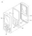
도 4는 본 발명의 제1실시예에 따른 개인휴대단말기의 구조를 도시한 사시도이고, 도 5는 본 발명의 제1실시예에 따른 개인휴대단말기의 구조를 도시한 단면도이다.4 is a perspective view showing the structure of a personal portable terminal according to the first embodiment of the present invention, Figure 5 is a cross-sectional view showing the structure of a personal portable terminal according to the first embodiment of the present invention.
도 4 및 도 5에서 도시한 바와 같이, 본 발명의 제1실시예에 따른 개인휴대단말기(10)는 슬라이드형 개인휴대단말기로서, 본체부(20), 슬라이드부(30), 데코 플레이트(40)를 포함한다.4 and 5, the personal portable terminal 10 according to the first embodiment of the present invention is a slide type personal portable terminal, the
상기 본체부(20)의 내부에는 각종 제어를 위한 인쇄회로기판(50)이 수용되어 있으며, 인쇄회로기판(50)의 상면에는 누름 조작시 온/오프 동작될 수 있도록 두께방향을 따라 탄성변형이 가능한 소위 메탈돔이라고 하는 복수개의 스위치(52)가 구비되어 있다. 아울러 상기 본체부(20)의 전면 하측에는 소정 크기의 개구부(22)가 형성되어 있으며, 상기 스위치(52)는 개구부(22)를 통해 외부로 노출될 수 있다.The inside of the
또한, 상기 인쇄회로기판(50) 상에는 조명을 위한 발광소자가 구비될 수 있으며, 경우에 따라서는 발광소자 대신 통상의 이엘시트(Electro luminessence Sheet)가 제공될 수도 있다.In addition, a light emitting device for illumination may be provided on the printed
상기 슬라이드부(30)는 본체부(20)의 상부에 중첩되도록 배치되며 통상의 슬라이딩모듈(도시하지 않음)을 통해 본체부(20)에 상대 슬라이딩 가능하게 연결되어 선택적으로 본체부(20)에 대해 상대 슬라이딩될 수 있다. 아울러 상기 본체부(20)의 개구부(22)는 슬라이드부(30)가 본체부(20)에 대해 슬라이딩됨에 따라 선택적으로 개폐될 수 있다. 또한, 상기 슬라이드부(30)의 전면에는 영상 정보를 출력하기 위한 디스플레이부(32) 및 상대방으로부터의 음성을 전달하기 위한 수화부가 구비될 수 있다.The
상기 데코 플레이트(40)는 본체부(20)의 전면에 결합되어 실질적으로 본체부(20)의 전면 외관을 형성함과 아울러, 키패드의 역할을 수행할 수 있도록 두께 방향을 따라 누름 조작 가능하게 버튼 영역이 형성되어 있다.The
즉, 상기 데코 플레이트(40)는 본체부(20)와 대응되는 형상으로 형성되어 본체부(20)의 전면에 결합되어 본체부(20)의 전면 외관을 형성하되, 개구부(22)에 대응되는 부위에는 누름 조작 가능하게 버튼 영역이 형성되어 있다. 또한, 상기 데코 플레이트(40)의 상측에는 소정 크기의 통과공(42)이 형성되어 있으며, 이 통과공(42)을 통해 본체부(20)와 슬라이드부(30)를 연결하는 슬라이딩모듈이 통과될 수 있다.That is, the
이러한 데코 플레이트(40)는 통상의 투광성 재질로 형성될 수 있다. 일 예로 상기 데코 플레이트(40)는 폴리프로필렌(PP), 방향성 폴리프로필렌(OPP), 폴리에틸렌테레프탈레이트(PET), 에틸렌비닐아세테이트(EVA), 폴리에틸렌(PE), 폴리염화비닐(PVC), 아크릴부타디엔스티렌(ABS), 폴리카보네이트(PC) 등의 재질로 형성될 수 있다.The
또, 상기 데코 플레이트(40)의 버튼 영역 상에 숫자 또는 문자 등을 표시하기 위한 버튼패턴(44)이 형성될 수 있으며, 상기 버튼패턴(44)에 의해 데코 플레이트(40)의 투광영역이 정의될 수 있다. 이러한 버튼패턴(44)은 다양한 방법에 의해서 형성될 수 있는 바, 일 예로 투광성 재질로 이루어진 데코 플레이트(40)의 표면 에 빛을 차단하는 코팅층을 형성한 후, 레이저 마킹 작업을 통해 투광영역에 해당되는 코팅층 부위를 부분적으로 제거함으로써 형성될 수 있다. 경우에 따라서는 별도의 버튼패턴이 배제된 상태로 데코 플레이트가 제공될 수도 있다.In addition, a
참고로 상기 데코 플레이트(40)의 버튼 영역이라 함은 각종 정보를 입력할 시 독립적으로 누름 조작되는 부위를 말한다. 일 예로 버튼 영역은 각 버튼패턴(44)에 대응되는 부위로 정의될 수 있으며, 이와 같은 버튼 영역은 요구되는 조건 및 설계 사양에 따라 다양하게 변경될 수 있다.For reference, the button area of the
또한, 상기 데코 플레이트(40)의 저면에는 탄성시트(60)가 제공될 수 있다. 상기 탄성시트(60)는 폴리우레탄와 같이 탄성과 유연성을 갖는 통상의 탄성재질로 형성되어 데코 플레이트(40)의 저면에 일체로 부착될 수 있다. 아울러 탄성시트(60)의 저면에는 데코 플레이트(40)를 누르는 힘이 각 스위치에 효과적으로 전달될 수 있도록 각 스위치에 대응되게 누름돌기(62)가 형성될 수 있다.In addition, an
그리고, 상기 본체부(20)의 전면에는 수용홈(23)이 형성될 수 있으며, 상기 데코 플레이트(40)는 수용홈에 수용될 수 있다. 이러한 수용홈(23)은 데코 플레이트(40)에 대응되는 형상 및 깊이를 갖도록 형성될 수 있다.In addition, an
또, 상기 본체부(20)와 데코 플레이트(40)의 상호 접촉면 중 어느 일측에는 고정돌기(46)가 형성될 수 있고, 상기 본체부(20)와 데코 플레이트(40)의 상호 접촉면 중 다른 일측에는 고정돌기(46)가 수용될 수 있도록 고정홈(26)이 형성될 수 있다. 이하에서는 데코 플레이트(40)의 저면에 고정돌기(46)가 형성되고 본체부(20)의 전면에 고정홈(26)이 형성된 예를 들어 설명하기로 한다. 이러한 고정돌 기(46) 및 고정홈(26)에 의해 본체부(20) 상에 배치된 데코 플레이트(40)의 위치가 고정될 수 있으며, 추후에 융착 등의 방법을 통해 데코 플레이트(40)는 본체부(20)에 일체로 고정될 수 있다.In addition, a fixing
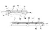
한편, 도 6 내지 도 9는 본 발명의 제1실시예에 따른 개인휴대단말기의 변형예를 각각 도시한 단면도 및 사시도이다. 아울러, 전술한 구성과 동일 및 동일 상당 부분에 대해서는 동일 또는 동일 상당한 참조 부호를 부여하고, 그에 대한 상세한 설명은 생략하기로 한다.6 to 9 are cross-sectional views and perspective views respectively showing modified examples of the personal portable terminal according to the first embodiment of the present invention. In addition, the same or equivalent reference numerals are given to the same or equivalent components as those described above, and detailed description thereof will be omitted.
도 6에서 도시한 바와 같이, 전술한 데코 플레이트(40)에는 버튼 영역의 주변을 따라 슬릿(48)이 형성될 수 있다. 이와 같은 구조는 어느 한곳의 버튼 영역이 누름 조작될 시 인접된 다른 버튼 영역으로 움직임이 전달되며 연동되는 것을 방지할 수 있게 하고, 그에 따른 오작동을 방지할 수 있게 한다. 이때, 상기 슬릿(48)의 형상 및 구조는 요구되는 조건 및 설계 사양 등에 따라 자유롭게 변경될 수 있으며 이와 같은 슬릿(48)의 형상 및 구조에 의해 본 발명이 제한되거나 한정되는 것은 아니다.As illustrated in FIG. 6, the
도 7에서 도시한 바와 같이, 전술한 데코 플레이트(40)는 금속시트(70)를 포함하여 제공될 수 있다. 상기 금속시트(70)는 경도가 우수한 통상의 금속재질로 형성될 수 있다. 일 예로 금속시트(70)로서는 구리나 구리합금, 스테인리스, 알루미늄, 티타늄, 플래티늄, 니켈 등의 금속재질로 이루어진 금속시트가 사용될 수 있다. 이러한 금속시트(70)는 플라스틱보다 경도가 우수하기 때문에 얇게 만들어도 딱딱한 형태를 유지하기가 용이하며, 일정 형상 강도를 유지하면서 용이하게 휘어 질 수 있다. 아울러 이러한 금속시트(70)는 그 저면에 형성되는 러버층(80)을 매개로 데코 플레이트(40)의 저면에 일체로 부착될 수 있다.As shown in FIG. 7, the above-described
그리고, 상기 금속시트(70)가 두께 방향을 따라 용이하게 누름 조작될 수 있도록 금속시트(70) 상에는 버튼 영역의 주변을 따라 소정 패턴 형태의 가이드슬릿(72)이 관통 형성될 수 있다. 일 예로 상기 가이드슬릿(72)은 버튼 영역의 주변을 따라 대략 'ㄷ' 형상으로 관통 형성되어 버튼 영역이 외팔보(cantilever) 방식으로 금속시트(70)에 연결되도록 구성할 수 있다. 이와 같은 가이드슬릿(72)의 형상 및 구조는 요구되는 조건 및 설계 사양 등에 따라 자유롭게 변경될 수 있다.In addition, a guide slit 72 having a predetermined pattern may be formed on the
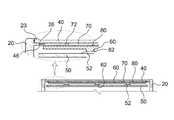
다르게는, 도 8과 같이 금속시트(70) 상에 각 버튼 영역에 해당되는 부위가 관통되도록 관통홀(73)을 형성할 수 있다. 경우에 따라서는 도 9와 같이 금속시트(70) 상에 전면적으로 복수개의 홀(74)을 관통 형성할 수 있으며, 이와 같은 경우 금속시트(70)는 일부분이 아닌 전체가 탄성적으로 누름 조작될 수 있다. 이 외에도 금속시트(70)는 다양한 구조로 형성될 수 있으며, 금속시트(70)의 구조에 의해 본 발명이 제한되거나 한정되는 것은 아니다. 경우에 따라서는 전술한 금속시트(70) 대신 금속재질로 형성되며 서로 독립적으로 누름 조작 가능하게 배치되는 복수개의 금속편이 제공될 수도 있다.Alternatively, as shown in FIG. 8, the through
한편, 도 10 및 도 11은 본 발명의 제2실시예에 따른 개인휴대단말기의 구조를 각각 도시한 사시도 및 단면도이다. 아울러, 전술한 구성과 동일 및 동일 상당 부분에 대해서는 동일 또는 동일 상당한 참조 부호를 부여하고, 그에 대한 상세한 설명은 생략하기로 한다.10 and 11 are a perspective view and a cross-sectional view showing the structure of a personal portable terminal according to a second embodiment of the present invention, respectively. In addition, the same or equivalent reference numerals are given to the same or equivalent components as those described above, and detailed description thereof will be omitted.
전술 및 도시한 본 발명에 실시예에서는 데코 플레이트가 슬라이드형 개인휴대단말기에 적용된 예를 들어 설명하고 있지만, 이러한 데코 플레이트는 바형 개인휴대단말기에 적용될 수 있다.In the above-described and illustrated embodiments of the present invention, a deco plate is described as an example applied to a slide type personal portable terminal, but such a deco plate may be applied to a bar type personal portable terminal.
즉, 도 10 및 도 11에서 도시한 바와 같이, 본 발명의 제2실시예에 따른 개인휴대단말기(100)는 전면 일측에 개구부(202) 및 디스플레이부(220)가 구비된 본체부(200), 상기 본체부(200)의 전면에 결합되어 전면 외관을 형성하며 개구부(202)에 대응되도록 두께 방향을 따라 누름 조작 가능하게 버튼 영역이 형성된 데코 플레이트(300)를 포함한다.That is, as shown in FIGS. 10 and 11, the personal
상기 본체부(200)의 전면에는 영상 정보를 출력하기 위한 디스플레이부(220)가 외부로 노출되도록 제공된다. 상기 본체부(200)의 내부에는 각종 제어를 위한 인쇄회로기판(500)이 수용되어 있으며, 상기 인쇄회로기판(500)의 상면에는 누름 조작시 온/오프 동작될 수 있도록 두께방향을 따라 탄성변형이 가능한 소위 메탈돔이라고 하는 복수개의 스위치(502)가 구비되어 있다. 아울러 상기 본체부(200)의 전면 하측에는 소정 크기의 개구부(202)가 형성되어 있으며, 상기 스위치(502)는 개구부(202)를 통해 외부로 노출될 수 있다.The front of the
상기 데코 플레이트(300)는 본체부(200)의 전면에 결합되어 실질적으로 본체부(200)의 전면 외관을 형성함과 아울러, 키패드의 역할을 수행할 수 있도록 두께 방향을 따라 누름 조작 가능하게 버튼 영역이 형성되어 있다. 또한, 상기 데코 플레이트(300)에는 디스플레이부(220)에 대응되게 노출공(302)이 형성되어 있으며, 이 노출공(302)을 통해 디스플레이부(220)가 데코 플레이트(300)의 외부로 노출될 수 있다.The
이러한 데코 플레이트(300)는 통상의 투광성 재질로 형성될 수 있다. 상기 데코 플레이트(300)의 버튼 영역 상에 숫자 또는 문자 등을 표시하기 위한 버튼패턴(304)이 형성될 수 있으며, 상기 버튼패턴(304)에 의해 데코 플레이트(300)의 투광영역이 정의될 수 있다.The
상기 데코 플레이트(300)의 저면에는 탄성시트(600)가 제공될 수 있다. 상기 탄성시트(600)는 폴리우레탄와 같이 탄성과 유연성을 갖는 통상의 탄성재질로 형성되어 데코 플레이트(300)의 저면에 일체로 부착될 수 있다. 아울러 탄성시트(600)의 저면에는 데코 플레이트(300)를 누르는 힘이 각 스위치에 효과적으로 전달될 수 있도록 각 스위치에 대응되게 누름돌기(602)가 형성될 수 있다.An
그리고, 상기 본체부(200)의 전면에는 수용홈(203)이 형성될 수 있으며, 상기 데코 플레이트(300)는 수용홈(203)에 수용될 수 있다. 이러한 수용홈(203)은 데코 플레이트(300)에 대응되는 형상 및 깊이를 갖도록 형성될 수 있다.In addition, an
또, 상기 데코 플레이트(300)의 저면에는 고정돌기(306)가 형성될 수 있고, 본체부(200)의 전면에는 고정돌기(306)이 수용될 수 있도록 고정홈(206)이 형성될 수 있다. 이러한 고정돌기(306) 및 고정홈(206)에 의해 본체부(200) 상에 배치된 데코 플레이트(300)의 위치가 고정될 수 있다.In addition, a fixing
전술한 실시예에 마찬가지로 상기 데코 플레이트(300)에는 버튼 영역의 주변을 따라 슬릿(도 6의 48 참조)이 형성될 수 있으며, 데코 플레이트(300)는 금속시트(도 7 내지 도 9의 70 참조)를 포함하여 제공될 수 있다.Similarly to the above-described embodiment, the
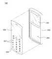
한편, 도 12는 본 발명의 제3실시예에 따른 개인휴대단말기의 구조를 도시한 사시도이다. 아울러, 전술한 구성과 동일 및 동일 상당 부분에 대해서는 동일 또는 동일 상당한 참조 부호를 부여하고, 그에 대한 상세한 설명은 생략하기로 한다.On the other hand, Figure 12 is a perspective view showing the structure of a personal portable terminal according to a third embodiment of the present invention. In addition, the same or equivalent reference numerals are given to the same or equivalent components as those described above, and detailed description thereof will be omitted.
전술 및 도시한 본 발명의 제2실시예에서는 데코 플레이트(300) 상에 별도의 노출공(302)이 형성되고, 이 노출공(302)을 통해 디스플레이부(220)가 노출되도록 구성된 예를 들어 설명하고 있지만, 경우에 따라서는 데코 플레이트(300') 상에 투광창(302')이 형성되며, 이 투광창(302')을 통해 디스플레이부(220)가 노출되도록 구성할 수 있다.In the above-described and illustrated second embodiment of the present invention, for example, a
즉, 도 12에서 도시한 바와 같이, 데코 플레이트(300') 상에는 본체부의 디스플레이부에 대응되게 투광창(302')이 형성될 수 있고, 상기 데코 플레이트(300')는 실질적으로 본체부(200)의 전면을 전면적으로 덮도록 배치될 수 있다. 이때 투광창(302')은 디스플레이부(220)를 덮도록 배치되는 바, 이에 따라 디스플레이부(220)는 투광창(302')을 통해 노출될 수 있다.That is, as illustrated in FIG. 12, a
이러한 투광창(302')은 투광성 재질로 이루어진 데코 플레이트(300') 상에 버튼패턴(304')을 형성할 시 함께 형성될 수 있다. 즉, 투광창(302')은 버튼패턴(304')과 마찬가지로 데코 플레이트(300')의 표면에 형성된 코팅층을 부분적으로 제거함으로써 형성될 수 있다. 다르게는, 데코 플레이트의 표면에 코팅층을 형성할 시 투광창에 대응되는 영역만을 배제하고 코팅층을 형성할 수도 있다.The light transmission window 302 'may be formed together when the button pattern 304' is formed on the decor plate 300 'made of a light transmitting material. That is, the
이와 같이 데코 플레이트(300')는 본체부(200)의 전면 외관을 형성함과 동시에 키패드의 역할을 수행할 수 있음은 물론 디스플레이부(200)를 보호하기 위한 보 호창의 역할을 함께 수행할 수 있다.As described above, the
이상에서 본 바와 같이, 본 발명에 따른 개인휴대단말기에 의하면 소형화 및 박형화에 기여할 수 있음은 물론 제작공정을 간소화하여 원가를 절감하고 생산성을 향상 시킬 수 있는 효과가 있다.As described above, the personal mobile terminal according to the present invention can contribute to miniaturization and thinning, as well as simplify the manufacturing process, thereby reducing costs and improving productivity.
특히, 본 발명은 데코 플레이트가 본체부의 하우징과 별도로 구성되어 본체부의 전면 외관을 형성함과 동시에 키패드의 역할을 병행할 수 있게 함으로써, 본체부의 하우징 자체를 투광성 재질로 형성하고, 하우징 상에 별도의 코팅층을 형성해야 하는 등 번거롭고 복잡한 공정을 배제할 수 있게 하며, 제작공정을 간소화할 수 있게 한다.In particular, the present invention is to form a front plate of the main body of the main body of the main body of the body portion separately configured to separate the housing of the main body and at the same time, thereby forming the housing itself of the body of the translucent material, and on the housing It is possible to eliminate cumbersome and complicated processes such as the need to form a coating layer, and to simplify the manufacturing process.
또한, 본 발명은 키패드의 획일화된 디자인에서 탈피할 수 있게 하며, 제품의 디자인 특성을 향상시키고 상품적 가치를 향상 시킬 수 있게 한다.In addition, the present invention makes it possible to deviate from the uniform design of the keypad, and to improve the product design characteristics and product value.
이와 같이 본 발명은 제품의 고급화에 기여할 수 있으며 급변하는 소비자의 욕구를 충족시킬 수 있는 효과가 있다.As described above, the present invention can contribute to the quality of the product and has the effect of satisfying the rapidly changing needs of consumers.
상술한 바와 같이, 본 발명의 바람직한 실시예를 참조하여 설명하였지만 해당 기술분야의 숙련된 당업자라면 하기의 청구범위에 기재된 본 발명의 사상 및 영역으로부터 벗어나지 않는 범위 내에서 본 발명을 다양하게 수정 및 변경시킬 수 있음을 이해할 수 있을 것이다.As described above, although described with reference to the preferred embodiment of the present invention, those skilled in the art various modifications and variations of the present invention without departing from the spirit and scope of the invention described in the claims below I can understand that you can.
Claims (20)
Translated fromKoreanPriority Applications (1)
| Application Number | Priority Date | Filing Date | Title |
|---|---|---|---|
| KR1020060135422AKR100852360B1 (en) | 2006-12-27 | 2006-12-27 | Personal portable device |
Applications Claiming Priority (1)
| Application Number | Priority Date | Filing Date | Title |
|---|---|---|---|
| KR1020060135422AKR100852360B1 (en) | 2006-12-27 | 2006-12-27 | Personal portable device |
Publications (2)
| Publication Number | Publication Date |
|---|---|
| KR20080060844A KR20080060844A (en) | 2008-07-02 |
| KR100852360B1true KR100852360B1 (en) | 2008-08-14 |
Family
ID=39813323
Family Applications (1)
| Application Number | Title | Priority Date | Filing Date |
|---|---|---|---|
| KR1020060135422AExpired - Fee RelatedKR100852360B1 (en) | 2006-12-27 | 2006-12-27 | Personal portable device |
Country Status (1)
| Country | Link |
|---|---|
| KR (1) | KR100852360B1 (en) |
Citations (6)
| Publication number | Priority date | Publication date | Assignee | Title |
|---|---|---|---|---|
| KR20000049437A (en)* | 2000-03-16 | 2000-08-05 | 곽철기 | Front-cover for communication equipment |
| KR200415225Y1 (en) | 2006-02-17 | 2006-04-28 | (주)지엔씨 | Keypad assembly and personal handheld terminal with same |
| KR20060090373A (en)* | 2005-02-07 | 2006-08-10 | 엘지전자 주식회사 | Front cover of mobile communication terminal |
| KR200426231Y1 (en)* | 2006-06-29 | 2006-09-12 | 주식회사 모젬 | Window-integrated keypad and wireless terminal with same |
| KR20060125005A (en)* | 2005-06-01 | 2006-12-06 | 주식회사 모젬 | Keypad manufacturing method of wireless terminal formed integrally with transparent window |
| KR100712304B1 (en) | 2006-04-19 | 2007-04-27 | 주식회사 삼영테크놀로지 | Manufacturing method of integrated metal front cover of portable terminal |
- 2006
- 2006-12-27KRKR1020060135422Apatent/KR100852360B1/ennot_activeExpired - Fee Related
Patent Citations (6)
| Publication number | Priority date | Publication date | Assignee | Title |
|---|---|---|---|---|
| KR20000049437A (en)* | 2000-03-16 | 2000-08-05 | 곽철기 | Front-cover for communication equipment |
| KR20060090373A (en)* | 2005-02-07 | 2006-08-10 | 엘지전자 주식회사 | Front cover of mobile communication terminal |
| KR20060125005A (en)* | 2005-06-01 | 2006-12-06 | 주식회사 모젬 | Keypad manufacturing method of wireless terminal formed integrally with transparent window |
| KR200415225Y1 (en) | 2006-02-17 | 2006-04-28 | (주)지엔씨 | Keypad assembly and personal handheld terminal with same |
| KR100712304B1 (en) | 2006-04-19 | 2007-04-27 | 주식회사 삼영테크놀로지 | Manufacturing method of integrated metal front cover of portable terminal |
| KR200426231Y1 (en)* | 2006-06-29 | 2006-09-12 | 주식회사 모젬 | Window-integrated keypad and wireless terminal with same |
Also Published As
| Publication number | Publication date |
|---|---|
| KR20080060844A (en) | 2008-07-02 |
Similar Documents
| Publication | Publication Date | Title |
|---|---|---|
| US6585435B2 (en) | Membrane keyboard | |
| KR100954764B1 (en) | User switchable mobile phone keypad | |
| KR100652750B1 (en) | Handheld terminal with protective input window | |
| KR100454203B1 (en) | Key-pad assembly for cellular phone | |
| EP1770965B1 (en) | Mobile terminal with a plurality of slidable keypads | |
| US20030112225A1 (en) | Electronic device having a movable keypad | |
| WO1998019434A1 (en) | Telecommunication apparatus having dual keypads | |
| US20070049075A1 (en) | Sliding device for portable terminal | |
| KR101172454B1 (en) | Case for portable terminal | |
| EP1417674A2 (en) | Keymat | |
| JP4190568B1 (en) | Mobile device | |
| JP4776524B2 (en) | Key input type electronic equipment | |
| KR100852360B1 (en) | Personal portable device | |
| KR200415225Y1 (en) | Keypad assembly and personal handheld terminal with same | |
| KR100840017B1 (en) | Keypad | |
| KR100870505B1 (en) | Keypad for personal portable device and method of manufacturing keypad | |
| KR20150068883A (en) | Key pad for mobile terminal | |
| KR100792585B1 (en) | Key input device | |
| KR100915985B1 (en) | Keypad for personal mobile device | |
| KR100837266B1 (en) | Key pad | |
| KR100843263B1 (en) | Key input device | |
| KR100837257B1 (en) | Keypad and its manufacturing method | |
| KR100774611B1 (en) | Integrated metal front cover for communication equipment | |
| KR100780900B1 (en) | Backlighting structure of the keypad | |
| US20070074965A1 (en) | Electronic device |
Legal Events
| Date | Code | Title | Description |
|---|---|---|---|
| A201 | Request for examination | ||
| PA0109 | Patent application | St.27 status event code:A-0-1-A10-A12-nap-PA0109 | |
| PA0201 | Request for examination | St.27 status event code:A-1-2-D10-D11-exm-PA0201 | |
| D13-X000 | Search requested | St.27 status event code:A-1-2-D10-D13-srh-X000 | |
| D14-X000 | Search report completed | St.27 status event code:A-1-2-D10-D14-srh-X000 | |
| E902 | Notification of reason for refusal | ||
| PE0902 | Notice of grounds for rejection | St.27 status event code:A-1-2-D10-D21-exm-PE0902 | |
| E13-X000 | Pre-grant limitation requested | St.27 status event code:A-2-3-E10-E13-lim-X000 | |
| P11-X000 | Amendment of application requested | St.27 status event code:A-2-2-P10-P11-nap-X000 | |
| P13-X000 | Application amended | St.27 status event code:A-2-2-P10-P13-nap-X000 | |
| E701 | Decision to grant or registration of patent right | ||
| PE0701 | Decision of registration | St.27 status event code:A-1-2-D10-D22-exm-PE0701 | |
| R18-X000 | Changes to party contact information recorded | St.27 status event code:A-3-3-R10-R18-oth-X000 | |
| PG1501 | Laying open of application | St.27 status event code:A-1-1-Q10-Q12-nap-PG1501 | |
| N231 | Notification of change of applicant | ||
| PN2301 | Change of applicant | St.27 status event code:A-3-3-R10-R13-asn-PN2301 St.27 status event code:A-3-3-R10-R11-asn-PN2301 | |
| GRNT | Written decision to grant | ||
| PR0701 | Registration of establishment | St.27 status event code:A-2-4-F10-F11-exm-PR0701 | |
| PR1002 | Payment of registration fee | St.27 status event code:A-2-2-U10-U11-oth-PR1002 Fee payment year number:1 | |
| PG1601 | Publication of registration | St.27 status event code:A-4-4-Q10-Q13-nap-PG1601 | |
| PN2301 | Change of applicant | St.27 status event code:A-5-5-R10-R11-asn-PN2301 | |
| PN2301 | Change of applicant | St.27 status event code:A-5-5-R10-R14-asn-PN2301 | |
| R18-X000 | Changes to party contact information recorded | St.27 status event code:A-5-5-R10-R18-oth-X000 | |
| PN2301 | Change of applicant | St.27 status event code:A-5-5-R10-R13-asn-PN2301 St.27 status event code:A-5-5-R10-R11-asn-PN2301 | |
| R18-X000 | Changes to party contact information recorded | St.27 status event code:A-5-5-R10-R18-oth-X000 | |
| PR1001 | Payment of annual fee | St.27 status event code:A-4-4-U10-U11-oth-PR1001 Fee payment year number:4 | |
| R18-X000 | Changes to party contact information recorded | St.27 status event code:A-5-5-R10-R18-oth-X000 | |
| FPAY | Annual fee payment | Payment date:20120608 Year of fee payment:5 | |
| PR1001 | Payment of annual fee | St.27 status event code:A-4-4-U10-U11-oth-PR1001 Fee payment year number:5 | |
| PN2301 | Change of applicant | St.27 status event code:A-5-5-R10-R13-asn-PN2301 St.27 status event code:A-5-5-R10-R11-asn-PN2301 | |
| FPAY | Annual fee payment | Payment date:20130809 Year of fee payment:6 | |
| PR1001 | Payment of annual fee | St.27 status event code:A-4-4-U10-U11-oth-PR1001 Fee payment year number:6 | |
| LAPS | Lapse due to unpaid annual fee | ||
| PC1903 | Unpaid annual fee | St.27 status event code:A-4-4-U10-U13-oth-PC1903 Not in force date:20140809 Payment event data comment text:Termination Category : DEFAULT_OF_REGISTRATION_FEE | |
| PC1903 | Unpaid annual fee | St.27 status event code:N-4-6-H10-H13-oth-PC1903 Ip right cessation event data comment text:Termination Category : DEFAULT_OF_REGISTRATION_FEE Not in force date:20140809 | |
| P22-X000 | Classification modified | St.27 status event code:A-4-4-P10-P22-nap-X000 |