KR100850792B1 - Device for generating the signals used for position tracing and the system including the same - Google Patents
Device for generating the signals used for position tracing and the system including the sameDownload PDFInfo
- Publication number
- KR100850792B1 KR100850792B1KR1020070009551AKR20070009551AKR100850792B1KR 100850792 B1KR100850792 B1KR 100850792B1KR 1020070009551 AKR1020070009551 AKR 1020070009551AKR 20070009551 AKR20070009551 AKR 20070009551AKR 100850792 B1KR100850792 B1KR 100850792B1
- Authority
- KR
- South Korea
- Prior art keywords
- ultrasonic
- ultrasonic signal
- signal
- signal generator
- generator
- Prior art date
- Legal status (The legal status is an assumption and is not a legal conclusion. Google has not performed a legal analysis and makes no representation as to the accuracy of the status listed.)
- Expired - Fee Related
Links
Images


Classifications
- G—PHYSICS
- G06—COMPUTING OR CALCULATING; COUNTING
- G06F—ELECTRIC DIGITAL DATA PROCESSING
- G06F3/00—Input arrangements for transferring data to be processed into a form capable of being handled by the computer; Output arrangements for transferring data from processing unit to output unit, e.g. interface arrangements
- G06F3/01—Input arrangements or combined input and output arrangements for interaction between user and computer
- G06F3/03—Arrangements for converting the position or the displacement of a member into a coded form
- G06F3/041—Digitisers, e.g. for touch screens or touch pads, characterised by the transducing means
- G06F3/043—Digitisers, e.g. for touch screens or touch pads, characterised by the transducing means using propagating acoustic waves
- G06F3/0433—Digitisers, e.g. for touch screens or touch pads, characterised by the transducing means using propagating acoustic waves in which the acoustic waves are either generated by a movable member and propagated within a surface layer or propagated within a surface layer and captured by a movable member
- G—PHYSICS
- G06—COMPUTING OR CALCULATING; COUNTING
- G06F—ELECTRIC DIGITAL DATA PROCESSING
- G06F3/00—Input arrangements for transferring data to be processed into a form capable of being handled by the computer; Output arrangements for transferring data from processing unit to output unit, e.g. interface arrangements
- G06F3/01—Input arrangements or combined input and output arrangements for interaction between user and computer
- G06F3/03—Arrangements for converting the position or the displacement of a member into a coded form
- G06F3/033—Pointing devices displaced or positioned by the user, e.g. mice, trackballs, pens or joysticks; Accessories therefor
- G06F3/0354—Pointing devices displaced or positioned by the user, e.g. mice, trackballs, pens or joysticks; Accessories therefor with detection of 2D relative movements between the device, or an operating part thereof, and a plane or surface, e.g. 2D mice, trackballs, pens or pucks
- G06F3/03545—Pens or stylus
- G—PHYSICS
- G06—COMPUTING OR CALCULATING; COUNTING
- G06F—ELECTRIC DIGITAL DATA PROCESSING
- G06F3/00—Input arrangements for transferring data to be processed into a form capable of being handled by the computer; Output arrangements for transferring data from processing unit to output unit, e.g. interface arrangements
- G06F3/01—Input arrangements or combined input and output arrangements for interaction between user and computer
- G06F3/03—Arrangements for converting the position or the displacement of a member into a coded form
- G06F3/033—Pointing devices displaced or positioned by the user, e.g. mice, trackballs, pens or joysticks; Accessories therefor
- G06F3/038—Control and interface arrangements therefor, e.g. drivers or device-embedded control circuitry
Landscapes
- Engineering & Computer Science (AREA)
- General Engineering & Computer Science (AREA)
- Theoretical Computer Science (AREA)
- Physics & Mathematics (AREA)
- Human Computer Interaction (AREA)
- General Physics & Mathematics (AREA)
- Acoustics & Sound (AREA)
- Measurement Of Velocity Or Position Using Acoustic Or Ultrasonic Waves (AREA)
- Length Measuring Devices Characterised By Use Of Acoustic Means (AREA)
Abstract
Translated fromKoreanDescription
Translated fromKorean도 1 은 종래의 위치 추적용 신호 발생 장치 구성을 도시하는 도면이다.1 is a diagram showing a conventional configuration of a signal generator for tracking position.
도 2 는 본 발명의 바람직한 제 1 실시예에 따른 위치 추적용 신호 발생 장치의 구성을 도시한 도면이다.2 is a diagram illustrating a configuration of a signal generator for tracking position according to a first embodiment of the present invention.
도 3 은 본 발명의 바람직한 제 1 실시예에 따라서 도 2 의 가이드부가 도 2 의 본체부에 결합된 경우에 가이드부의 단면을 도시한 도면이다.3 is a cross-sectional view of the guide part when the guide part of FIG. 2 is coupled to the main body part of FIG. 2 according to the first preferred embodiment of the present invention.
도 4 는 본 발명의 바람직한 제 1 실시예에 따라서 생성된 초음파신호의 파형과, 각 초음파신호가 중첩되어 증폭되는 과정을 설명하는 도면이다.FIG. 4 is a diagram illustrating a waveform of an ultrasonic signal generated according to a first preferred embodiment of the present invention and a process of overlapping and amplifying each ultrasonic signal.
도 5 는 본 발명의 바람직한 제 1 실시예에 입력 시스템의 전체 구성과 입력 방법을 설명하는 도면이다.5 is a view for explaining the overall configuration and input method of the input system in a first preferred embodiment of the present invention.
도 6 은 본 발명의 바람직한 제 2 실시예에 입력 시스템의 전체 구성과 입력 방법을 설명하는 도면이다.6 is a view for explaining the overall configuration and input method of the input system in a second preferred embodiment of the present invention.
본 발명은 위치 추적용 신호 발생 장치, 및 위치 추적용 신호 발생 장치의 위치를 추적하여 정보를 입력하는 위치 추적 입력 장치를 포함하는 입력 시스템에 관한 것이다.The present invention relates to an input system including a location tracking signal generating device and a location tracking input device for inputting information by tracking a location of the location tracking signal generating device.
위치 추적 입력 장치란, 사용자가 움직이는 위치 추적용 신호 발생 장치의 위치를 인식하여, 신호 발생 장치의 위치 및 궤적에 따른 정보를 입력하는 것으로서, 현재로서는 입력펜으로 구현되는 위치 추적용 신호 발생 장치와 함께 자연 필기 입력 시스템으로서 구현되어 사용되고 있다. 따라서, 이하에서는 설명의 편의를 위하여, 본 발명의 위치 추적용 신호 발생 장치 및 위치 추적 입력 장치가 자연 필기 입력 시스템으로 구현된 예를 중심으로 본 발명의 기술적 사상들을 설명한다.The location tracking input device recognizes a location of a location tracking signal generator that a user moves, and inputs information according to the location and trajectory of the signal generating device. Together, it is implemented and used as a natural handwriting input system. Therefore, hereinafter, for the convenience of description, the technical idea of the present invention will be described with reference to an example in which the location tracking signal generator and the location tracking input device are implemented as a natural handwriting input system.
자연 필기 입력 시스템은 테이블릿 PC 상의 자연 필기 인식 방식과 달리, 입력펜에서 생성되는 기준 신호와 초음파 신호가 자연 필기 입력 장치에 수신되는 시간 차이를 이용하여 거리를 계산함으로써 입력펜의 좌표를 인식하고, 입력펜의 이동 좌표를 연결함으로써 입력펜의 궤적을 인식하여 입력한다. 이 때, 기준 신호로서는 적외선(IR) 또는 무선 주파수 신호(RF) 또는 전자기 유도 신호(EM)를 사용한다.Unlike the natural handwriting recognition method on the tablelet PC, the natural handwriting input system recognizes the coordinates of the input pen by calculating the distance using the time difference between the reference signal generated by the input pen and the ultrasonic signal received by the natural handwriting input device. By connecting the movement coordinates of the input pen, the trajectory of the input pen is recognized and input. At this time, infrared (IR) or radio frequency signal (RF) or electromagnetic induction signal (EM) is used as the reference signal.
종래의 위치 추적용 신호 발생 장치 구성을 도 1 에 도시하였다. 도 1 를 참조하면, 종래의 위치 추적용 신호 발생 장치는 펜타입으로 구현되어 입력펜의 본체부(10)에, 전원을 공급하는 전원부(15), 기준 신호를 발생시키는 기준신호 발생부(13), 및 초음파 신호를 발생시키는 초음파 발생부(17), 기준신호 발생부(13)와 초음파 발생부(17)를 제어하는 제어부(11)를 포함한다.1 illustrates a conventional configuration of a signal generator for tracking position. Referring to FIG. 1, a conventional position tracking signal generator is implemented in a pen type to supply power to a
아울러, 사용자가 실제로 종이위에 기록할 수 있도록 내부에 잉크를 포함하는 펜심부(19), 또는 단순히 사용자의 필기감을 향상시키기 위하여 본체부의 중심을 관통하는 펜심부(19)를 포함하고, 펜심부(19)는 원통형으로 형성된 초음파 발생부(17)를 관통하며, 외부 하우징부가 초음파 발생부(17) 및 펜심부(19)를 둘러싸며 본체부와 결합된다. 이 때, 초음파 발생부(17)는 피에조 필름으로 형성되는 것이 일반적이다.In addition, the
또한, 도 1 에 도시된 바와 같이, 외부 하우징부(20)는 초음파 발생부(17)가 생성한 초음파가 외부로 방출되도록 둘레에 관통부(22)가 형성되어 있다.In addition, as illustrated in FIG. 1, the
한편, 이러한 종래의 위치 추적용 신호 발생 장치의 초음파 발생부(17)에서 생성된 초음파 신호의 도달 거리는 초음파 신호의 출력이 클수록 길어진다.Meanwhile, the reach distance of the ultrasonic signal generated by the
따라서, 입력 시스템의 초음파 신호를 수신하는 수신부가 위치 추적용 신호 발생 장치와 근거리에 있는 경우에는 위치 추적용 신호 발생 장치에서 발생되는 초음파 신호의 크기가 크게 문제되지 않으나, 초음파 신호를 수신하는 수신부가 위치 추적용 신호 발생 장치로부터 원거리에 배치되어 있는 경우에는, 초음파 신호가 초음파 신호 수신부까지 도달하지 않아 위치 추적용 신호 발생 장치의 위치를 정확하게 추적할 수 없는 문제점이 존재한다.Therefore, when the receiver for receiving the ultrasonic signal of the input system is located near the position tracking signal generator, the magnitude of the ultrasonic signal generated by the position tracking signal generator does not matter, but the receiver for receiving the ultrasonic signal does not matter. In the case of being disposed remotely from the position tracking signal generator, there is a problem in that the ultrasonic signal does not reach the ultrasonic signal receiver so that the position of the position tracking signal generator cannot be accurately tracked.
이러한, 문제를 해결하기 위해서 종래에는 초음파 신호의 출력을 크게하기 위한 방식이 제안되었으나, 초음파 신호의 출력을 크게 하려면 초음파 신호를 발생시키기 위하여 펜심부(19) 둘레를 감싸는 피에조 필름의 길이가 길어지고, 이에 비례하여 입력펜으로서 구현되는 위치 추적용 신호 발생 장치의 두께가 두꺼워져 사 용자들이 사용하기에 부적합한 문제점이 존재한다.In order to solve this problem, conventionally, a method for increasing the output of the ultrasonic signal has been proposed, but in order to increase the output of the ultrasonic signal, the length of the piezo film surrounding the
본 발명이 이루고자 하는 기술적 과제는 위치 추적용 신호 발생 장치의 두께를 증가시키지 않으면서도, 초음파 신호의 도달 거리를 증가시킬 수 있는 위치 추적용 신호 발생 장치 및 이를 이용하는 입력 시스템을 제공하는 것이다.An object of the present invention is to provide a location tracking signal generator and an input system using the same that can increase the reach of the ultrasonic signal without increasing the thickness of the location tracking signal generator.
상술한 기술적 과제를 이루기 위한 본 발명의 위치 추적용 신호 발생 장치는, 소정 거리만큼 이격 배치되어 소정의 제어 신호에 따라서 각각 초음파신호를 발생시키는 복수의 초음파신호 발생부; 복수의 초음파신호 발생부에서 발생된 초음파신호들이 상호 중첩되어 증폭되도록 제어 신호를 생성하여 복수의 초음파신호 발생부로 각각 출력하는 제어부; 및 초음파신호가 방출되도록 방출부가 형성되고, 복수의 초음파신호 발생부를 내부에 수용하면서 초음파신호 발생부가 지지되는 본체부와 결합되는 가이드부를 포함한다.According to an aspect of the present invention, there is provided a position tracking signal generator, comprising: a plurality of ultrasonic signal generators disposed to be spaced apart by a predetermined distance to generate ultrasonic signals according to predetermined control signals; A control unit for generating a control signal so that the ultrasonic signals generated by the plurality of ultrasonic signal generators overlap each other and amplified, and outputting the control signals to the plurality of ultrasonic signal generators; And a guide unit configured to emit an ultrasonic signal and to receive a plurality of ultrasonic signal generators therein and to be coupled with a main body unit on which the ultrasonic signal generator is supported.
또한, 상술한 제어부는 중첩된 초음파신호가 방출부를 통해서 방출되도록, 방출부로부터 원거리에 배치된 초음파신호 발생부부터 일정한 시간간격을 두고 제어 신호를 생성하여 출력할 수 있다.In addition, the controller may generate and output a control signal at a predetermined time interval from the ultrasonic signal generator disposed at a distance from the emitter so that the superposed ultrasonic signals are emitted through the emitter.
한편, 상술한 기술적 과제를 이루기 위한 본 발명의 입력 시스템은, 소정 거리만큼 이격 배치되어 소정의 제어 신호에 따라서 각각 초음파신호를 발생시키는 복수의 초음파신호 발생부와, 초음파신호가 방출되도록 방출부가 형성되고, 복수의 초음파신호 발생부를 내부에 수용하면서 초음파신호 발생부가 지지되는 본체부와 결합되는 가이드부를 포함하는 위치 추적용 신호 발생 장치; 및 위치 추적용 신호 발생 장치와 유선으로 연결되어, 소정의 시간 주기로 복수의 초음파신호 발생부에서 발생된 초음파신호들이 상호 중첩되어 증폭되도록 제어 신호를 생성하여 복수의 초음파신호 발생부로 각각 출력하는 제어장치를 포함한다.On the other hand, the input system of the present invention for achieving the above-described technical problem, a plurality of ultrasonic signal generators are arranged spaced apart by a predetermined distance to generate an ultrasonic signal according to a predetermined control signal, respectively, and the emission unit so that the ultrasonic signal is emitted A signal generator for position tracking including a guide unit coupled to a main body unit on which the ultrasonic signal generator is supported while receiving the plurality of ultrasonic signal generators therein; And a control device connected to a location tracking signal generator in a wired manner, to generate a control signal so that the ultrasonic signals generated by the plurality of ultrasonic signal generators are amplified by overlapping each other at predetermined time periods, and outputting the control signals to the plurality of ultrasonic signal generators, respectively. It includes.
이하, 첨부된 도면을 참조하여 본 발명의 바람직한 실시예들을 설명한다.Hereinafter, preferred embodiments of the present invention will be described with reference to the accompanying drawings.
도 2 는 본 발명의 바람직한 실시예에 따른 위치 추적용 신호 발생 장치의 구성을 도시한 도면이다. 도 2 를 참조하면 본 발명의 바람직한 실시예에 따른 위치 추적용 신호 발생 장치는 물리적으로 크게 본체부(200)와 본체부(200)와 결합되는 가이드부(300)로 구성된다.2 is a diagram illustrating a configuration of a signal generator for tracking position according to a preferred embodiment of the present invention. Referring to FIG. 2, the position tracking signal generator according to the preferred embodiment of the present invention includes a
본체부(200)에는 전원부(230), 초음파신호 생성부(240), 기준신호 발생부(220), 제어부(210), 및 펜심부(250)가 설치된다. 전원부(230)는 초음파신호 생성부(240), 기준신호 발생부(220), 및 제어부(210)로 전원을 공급하고, 기준신호 발생부(220)는 전원을 공급받아 제어부(210)로부터 입력된 제어신호에 따라서 기준신호를 발생시킨다. 본 발명의 기준신호로서는 적외선 신호(IR) 또는 무선 주파수(RF) 혹은 전자기 유도 신호(EM)가 이용될 수 있다.The
펜심부(250)는 일반적인 펜을 이용한 필기감만을 제공하도록 초음파신호 생성부(240)의 말단에 형성될 수 있고, 실제로 사용자가 필기를 수행할 수 있도록 내부에 잉크를 포함하여 초음파신호 생성부(240)를 관통하여 본체부(200) 내부로 삽입될 수도 있다.The
초음파신호 생성부(240)는 제어부(210)로부터 제어신호가 입력되면 진동에 의해서 초음파신호를 발생시키는 복수의 초음파신호 발생부(240a,240b), 펜심부(250)가 수납될 수 있도록 중심에 실린더 형상의 공간이 형성된 심부(242), 및 가이드부(300)의 내면과 밀착되어 가이드부(300) 내에서 초음파신호 발생부(240)의 위치를 고정시키는 지지부(248)를 포함하여 구성된다.When the control signal is input from the
복수의 초음파신호 발생부(240a,240b) 각각은 일정한 거리(L1)만큼 서로 이격되어, 심부(242)의 외주면을 둘러싸도록 설치되거나 심부(242)의 일정 영역에만 설치된다. 복수의 초음파신호 발생부(240a,240b) 각각은 제어신호에 따라서 전원부(230)로부터 인가된 전기 에너지를 진동으로 변환하여 초음파를 발생시키고, 피에조 필름과 같은 압전 소자로서 구현되는 것이 바람직하다.Each of the plurality of
비록, 도 2에는 2개의 초음파신호 발생부(240a,240b)가 설치된 것으로 도시하였으나, 3이상의 초음파신호 발생부도 설치될 수 있으며, 이 때, 각각 초음파신호 발생부는 서로 다른 이격 거리로 배치될 수도 있으나, 동일한 이격 거리마다 배치되는 것이 바람직하다.Although two
또한, 도 2 에 도시된 바와 같이, 초음파신호 생성부(240)는 사용자가 입력펜을 이용하여 필기 수행시 지면과 가깝게 위치(예컨대, "입력펜의 하단")하도록 배치되는 것이 바람직하고, 제어부(210), 기준신호 발생부(220), 및 전원부(230)의 위치는 본체부(200)내에서 임의로 배치될 수 있다.In addition, as illustrated in FIG. 2, the
한편, 가이드부(300)는 그 내부에 초음파신호 생성부(240)를 수용하도록 공간이 형성되어 있고, 내부에 수용된 초음파신호 생성부(240)를 감싸면서 본체부(200)와 결합된다.On the other hand, the
가이드부(300)는 하부 가이드부(310)와 상부 가이드부(320)로 구성되는데, 상부 가이드부(320)의 단면은 본체부(200)와 끼움 결합, 나사 결합 또는 접착 결합의 방식으로 본체부(200)와 결합될 수 있도록 끼움부 또는 나사산이 형성되어 있다.
하부 가이드부(310)의 외주면에는 가이드부(300) 내부에 수용된 초음파신호 발생부(240a,240b)에서 발생된 초음파 신호가 외부로 방출될 수 있도록 방출부(330)가 형성되어 있다. 방출부(330)의 길이는 지면과 가장 가깝도록 설치된 초음파신호 발생부(최하단 초음파신호 발생부:240a) 전체가 외부에서 관찰될 수 있는 길이로 형성되는 것이 바람직하다. 즉, 최하단 초음파신호 발생부(240a)에서 발생된 초음파 신호는 초음파신호 생성부(240)와 가이드부(300) 사이에 형성된 가이드 경로를 따라 진행함이 없이 직접 공기중으로 방출될 수 있도록 형성되는 것이 바람직하다.On the outer circumferential surface of the
한편, 상부 가이드부(320)는 내부에서 수용된 초음파신호 발생부(상단 초음파신호 발생부;240b)에서 발생된 초음파신호가 방출부(330)를 통해서 방출되도록 상단 초음파신호 발생부(240b)와의 사이에 가이드 경로를 형성한다. 따라서, 상단 초음파신호 발생부(240b)에서 발생된 초음파 신호는 가이드 경로를 따라서 지면 방향으로 하강하여 방출부(300)를 통해서 공기중으로 방출된다.On the other hand, the
이 때, 초음파신호 생성부(240)에 3이상의 초음파신호 발생부가 설치된 경우에, 지면 방향의 말단에 배치된 최하단 초음파신호 발생부를 제외한 나머지 초음파신호 발생부는 상부 가이드(320)에 의해서 감싸지도록 수용되고, 이들 초음파신호 발생부에서 발생된 초음파신호들은 가이드 경로를 따라서 방출부(330)로 진행하여 공기중으로 방출된다.In this case, when three or more ultrasonic signal generators are installed in the
한편, 제어부(210)는 소정의 시간 주기마다 초음파신호 생성부(240)와 기준신호 발생부(220)가 각각 초음파신호와 기준신호를 발생시키도록 제어신호를 초음파신호 생성부(240)와 기준신호 발생부(220)로 출력한다.On the other hand, the
제어부(210)는 초음파신호 발생부(240a,240b) 각각이 소정의 시간 간격으로 초음파신호를 발생시킴으로써, 각 초음파신호 발생부(240a,240b)에서 발생된 초음파 신호들이 상호 중첩되어 증폭되도록 제어신호를 생성하여 각 초음파신호 발생부(240a,240b)로 출력한다.The
도 3 은 본 발명의 바람직한 실시예에 따라서 가이드부(300)가 본체부(200)에 결합된 경우에 가이드부(300)의 단면을 도시한 도면이다. 도 3 을 참조하면, 초음파신호 생성부(240)가 가이드부(300)내로 삽입되면 펜심부(250)가 초음파신호 생성부(240)의 심부(242) 및 하부 가이드부(310)를 관통하여 외부로 돌출되고, 본체부(200)와 상부 가이드부(320)가 밀착되도록 결합되어 초음파신호 발생부(240a,240b)에서 발생된 초음파가 지면방향의 반대편으로 유출되는 것을 차단한다.3 is a cross-sectional view of the
또한, 초음파신호 생성부(240)가 가이드부(300)에 삽입된 상태에서 초음파신호 생성부(240)의 심부(242)와 가이드부(300)의 내면 사이에는 일정한 공간인 가이드 경로(350)가 형성되고, 초음파신호 발생부(240a,240b)에서 발생된 초음파신호는 가이드 경로(340)를 따라서 진행하여 초음파 방출부(330)로 방출된다.In addition, the
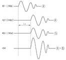
도 4 는 본 발명의 바람직한 제 1 실시예에 따라서 생성된 초음파신호의 파형과, 각 초음파신호가 중첩되어 증폭되는 과정을 설명하는 도면이다. 도 4 를 더 참조하면, 제어부(210)가 일정한 시간 간격으로 기준신호 및 초음파신호의 발생을 지시하는 제어신호를 생성하여 기준신호 발생부(220) 및 방출부(330)로부터 원거리의 초음파신호 발생부(240b)로 출력한다.FIG. 4 is a diagram illustrating a waveform of an ultrasonic signal generated according to a first preferred embodiment of the present invention and a process of overlapping and amplifying each ultrasonic signal. 4, the
제어신호를 수신한 기준신호 발생부(220)는 적외선신호 또는 무선주파수신호로서 구현되는 기준신호를 발생시키고, 초음파신호 발생부(240b)는 초음파신호를 발생시킨다(401:도 4 의 ⓐ 참조).The
초음파신호 발생부(240b)에서 발생된 초음파신호(ⓐ)는 가이드경로(350)를 따라서 방출부(330) 방향으로 진행한다(402).The ultrasonic signal ⓐ generated by the
한편, 제어부(210)는 초음파신호 발생부(240b)에서 발생된 초음파신호(ⓐ)가 초음파신호 발생부(240a)에 도달하는 시간이 되면, 즉, 초음파신호(ⓐ)가 초음파신호 발생부(240a,240b)간의 이격거리(L1)만큼 진행되면, 초음파신호의 발생을 지시하는 제어신호를 초음파신호 발생부(240a)로 출력하여, 이미 발생된 초음파신호와 동일한 주파수와 위상으로 초음파신호를 발생시킨다(403:도 4 의 ⓑ 참조).On the other hand, the
그러면, 초음파신호(ⓐ)와 초음파신호(ⓑ)는 상호 중첩되어 증폭된 초음파신호(ⓐ+ⓑ)가 발생되고, 증폭된 초음파신호는 방출부(330)을 통해서 공기중으로 방출된다.Then, the ultrasonic signal ⓐ and the ultrasonic signal ⓑ overlap each other to generate an amplified ultrasonic signal ⓐ + ⓑ, and the amplified ultrasonic signal is emitted into the air through the
도 5 는 본 발명의 바람직한 제 1 실시예에 입력 시스템의 전체 구성과 입력 방법을 설명하는 도면이다.5 is a view for explaining the overall configuration and input method of the input system in a first preferred embodiment of the present invention.
도 5 를 참조하여 본 발명의 바람직한 실시예에 따른 입력 시스템의 동작을 살펴보면, 본체부(200)와 가이드부(300)가 결합된 위치 추적용 신호 발생 장치(50a:이하, "입력펜"이라 칭함)의 제어부(210)는 소정의 시간 주기로 기준 신호 및 초음파 신호를 생성하도록 지시하는 제어 신호를 생성하여 기준신호 발생부(220) 및 초음파신호 생성부(240)로 출력한다.Looking at the operation of the input system according to a preferred embodiment of the present invention with reference to Figure 5, the position tracking
제어부(210)로부터 제어신호가 입력되면 기준신호 발생부(220)는 기준신호를 발생시키고, 초음파신호 생성부(240)의 초음파신호 발생부(240a)와 초음파신호 발생부(240b)는 상술한 바와 같은 일정한 시간 간격으로 순차적으로 초음파신호를 발생시키고, 각각 발생된 초음파신호는 중첩되어 증폭된 상태로 방출부(330)를 통해서 공기중으로 방출된다.When the control signal is input from the
위치 추적 입력 장치(60a)는 기준 신호를 수신하는 기준신호 수신센서(40)와 초음파 신호를 수신하는 복수의 초음파신호 수신센서(30a,30b)를 구비한다. 이 때, 초음파신호 수신센서(30a,30b)들은 소정의 거리만큼 이격되어 설치된다.The position tracking
입력펜(50a)의 (x,y) 좌표는 다음의 수학식 1을 x 및 y 에 대해서 풀면 구할 수 있다.The (x, y) coordinates of the
b2=(c-x)2+y2b2 = (cx)2 + y2
수학식 1에서 기준 신호인 적외선 또는 무선 주파수 신호가 빛의 속도로 진 행하므로 입력펜(50a)에서 생성됨과 동시에 기준신호 수신센서(40)에 수신된다고 간주하여, 거리 a 및 b 는 기준 신호가 수신된 시간과 초음파 신호가 좌측 초음파 센서(30a)와 우측 초음파 센서(30b)에 각각 수신된 시간간의 차이에 음속을 곱하여 구할 수 있고, 거리 c 는 사전에 설정된 값이므로, a, b, 및 c 값을 수학식 1 에 적용하여 (x,y) 좌표를 구할 수 있고, 입력펜(50a)이 움직인 좌표값들을 이용하여 문자와 같은 사용자가 필기를 수행한 내용을 입력할 수 있다.Since the infrared or radio frequency signal, which is a reference signal in Equation 1, proceeds at the speed of light, it is assumed that the reference signal is generated by the
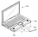
도 6 은 본 발명의 바람직한 제 2 실시예에 입력 시스템의 전체 구성과 입력 방법을 설명하는 도면이다.6 is a view for explaining the overall configuration and input method of the input system in a second preferred embodiment of the present invention.
제 2 실시예의 위치 추적용 신호 발생 장치(50b)는 제 1 실시예의 위치 추적용 신호 발생 장치(50a)의 구성에서 본체부(200)에 설치되는 제어부(210), 기준신호 발생부(220), 및 전원부(230)가 생략된다는 점을 제외하고, 초음파신호 생성부(240) 및 가이드부(300)의 구조적인 구성은 제 1 실시예와 동일하다.The position tracking
즉, 제어부(210), 기준신호 생성부(220), 전원부(230)가 포함되지 않는다는 점을 제외하면, 본체부(200)에 초음파신호 생성부(240) 및 펜심부(250)가 포함되고, 가이드부(300)가 초음파신호 생성부(240)를 내부에 수용하면서 본체부(200)와 결합되는 구조적인 구성은 제 1 실시예와 동일하며, 초음파신호 생성부(240)가 제어신호와 전력을 위치 추적 입력 장치(60b)로부터 유선으로 입력받아 초음파신호를 발생시킨다는 점에서 차이가 있다. 따라서, 제 1 실시예와 다른 구성 및 동작 방식에 대해서만 설명한다.That is, except that the
도 6 을 참조하면, 제 2 실시예의 위치 추적용 신호 발생 장치(50b)는 위치 추적 입력 장치(60b)와 유선으로 연결되어 전력을 공급받는다. 또한, 위치 추적 입력 장치(60b)는 위치 추적용 신호 발생 장치(50b: 이하, "입력펜"이라 칭함)로 하여금 초음파 신호를 발생시키도록 지시하는 제어 신호를 소정의 시간 주기로 생성하여 입력펜(50b)으로 출력한다.Referring to FIG. 6, the position tracking
제어신호를 입력받은 입력펜(50b)의 각 초음파신호 발생부(240a,240b)는 일정한 시간 간격으로 초음파신호를 생성하여 증폭된 초음파신호를 초음파 방출부(330)를 통해서 방출하고, 초음파신호는 위치 추적 입력 장치(60b)에 설치된 복수의 센서(30a 및 30b)에 수신된다.Each of the
위치 추적 입력 장치(60b)는 초음파 신호 발생을 지시하는 제어신호를 입력펜(50b)으로 출력한 시간을 기준 시간으로 설정하고, 기준시간으로부터 복수의 초음파 센서에 초음파 신호가 수신된 순간까지의 시간차를 이용하여 제 1 실시예와 동일한 방식으로 입력펜(50b)의 위치를 측정하여 입력을 수행할 수 있다.The position tracking
지금까지 본 발명의 바람직한 실시예들을 중심으로 본 발명의 위치 추적용 신호 발생 장치와 이를 이용하는 입력 시스템에 대해서 설명하였다. 본 발명이 속하는 기술 분야에서 통상의 지식을 가진 자는 본 발명이 본 발명의 본질적인 특성에서 벗어나지 않는 범위에서 변형된 형태로 구현될 수 있음을 이해할 수 있을 것이다.So far, the position tracking signal generator and the input system using the same have been described with reference to the preferred embodiments of the present invention. Those skilled in the art will appreciate that the present invention can be implemented in a modified form without departing from the essential features of the present invention.
예컨대, 상술한 실시예들에서는 초음파신호 생성부(240)가 2개의 초음파신호 발생부(240a,240b)를 포함하는 것으로 설명하였으나, 2이상의 초음파신호 발생부가 일정한 간격으로 서로 이격되어 배치되고, 최상단 초음파신호 발생부에서부터 차례 로, 초음파신호가 인접한 초음파신호 발생부까지 진행하는 시간간격으로 초음파신호를 발생시켜 증폭된 초음파신호를 방출하도록 구성될 수도 있다.For example, in the above-described embodiments, the
그러므로 개시된 실시예들은 한정적인 관점이 아니라 설명적인 관점에서 고려되어야 한다. 본 발명의 범위는 전술한 설명이 아니라 특허청구범위에 나타나 있으며, 그와 동등한 범위 내에 있는 모든 차이점은 본 발명에 포함된 것으로 해석되어야 할 것이다.Therefore, the disclosed embodiments should be considered in descriptive sense only and not for purposes of limitation. The scope of the present invention is shown in the claims rather than the foregoing description, and all differences within the scope will be construed as being included in the present invention.
상술한 바와 같이, 본 발명의 위치 추적용 신호 발생 장치는 복수의 초음파신호 발생부가 발생시킨 고주파수의 초음파신호가 중첩되어 증폭되도록 일정한 시간간격으로 초음파신호를 발생시킴으로써 초음파신호의 세기를 증가시켜 도달 거리를 증가시키는 효과가 있다.As described above, the position tracking signal generating apparatus of the present invention increases the intensity of the ultrasonic signal by generating the ultrasonic signal at a predetermined time interval so that the ultrasonic signals of the high frequency generated by the plurality of ultrasonic signal generators are overlapped and amplified, thereby increasing the reach distance. Has the effect of increasing.
또한, 본 발명의 상술한 구성적 특징으로 인해서, 초음파신호의 세기를 증가시키기 위해서 크기가 크며 주파수가 낮은 초음파 센서를 이용하므로 초래되는 위치 추적용 신호 발생 장치의 두께가 두꺼워지는 종래기술의 문제점을 해결하는 효과가 있다.In addition, due to the above-described configuration features of the present invention, the problem of the prior art that the thickness of the position tracking signal generator caused by using a large size and low frequency ultrasonic sensor to increase the intensity of the ultrasonic signal is thickened. It is effective to solve.
Claims (3)
Translated fromKoreanPriority Applications (1)
| Application Number | Priority Date | Filing Date | Title |
|---|---|---|---|
| KR1020070009551AKR100850792B1 (en) | 2007-01-30 | 2007-01-30 | Device for generating the signals used for position tracing and the system including the same |
Applications Claiming Priority (1)
| Application Number | Priority Date | Filing Date | Title |
|---|---|---|---|
| KR1020070009551AKR100850792B1 (en) | 2007-01-30 | 2007-01-30 | Device for generating the signals used for position tracing and the system including the same |
Publications (2)
| Publication Number | Publication Date |
|---|---|
| KR20080071384A KR20080071384A (en) | 2008-08-04 |
| KR100850792B1true KR100850792B1 (en) | 2008-08-06 |
Family
ID=39882161
Family Applications (1)
| Application Number | Title | Priority Date | Filing Date |
|---|---|---|---|
| KR1020070009551AExpired - Fee RelatedKR100850792B1 (en) | 2007-01-30 | 2007-01-30 | Device for generating the signals used for position tracing and the system including the same |
Country Status (1)
| Country | Link |
|---|---|
| KR (1) | KR100850792B1 (en) |
Cited By (1)
| Publication number | Priority date | Publication date | Assignee | Title |
|---|---|---|---|---|
| KR101125101B1 (en) | 2011-06-07 | 2012-03-21 | (주)펜앤프리 | Apparatus for generating signal |
Families Citing this family (3)
| Publication number | Priority date | Publication date | Assignee | Title |
|---|---|---|---|---|
| KR101521773B1 (en)* | 2008-11-27 | 2015-05-28 | 삼성전자주식회사 | Method and apparatus for location tracking |
| KR101039399B1 (en)* | 2009-07-21 | 2011-06-08 | (주)펜앤프리 | Signal generator |
| KR101033543B1 (en)* | 2009-07-21 | 2011-05-11 | (주)펜앤프리 | Information input system and method using ultrasonic signals |
Citations (2)
| Publication number | Priority date | Publication date | Assignee | Title |
|---|---|---|---|---|
| JPH07182096A (en)* | 1993-12-24 | 1995-07-21 | Fuotoron:Kk | Coordinate reading device |
| KR20020033608A (en)* | 1999-04-14 | 2002-05-07 | 추후제출 | Presentation board digitizers |
- 2007
- 2007-01-30KRKR1020070009551Apatent/KR100850792B1/ennot_activeExpired - Fee Related
Patent Citations (2)
| Publication number | Priority date | Publication date | Assignee | Title |
|---|---|---|---|---|
| JPH07182096A (en)* | 1993-12-24 | 1995-07-21 | Fuotoron:Kk | Coordinate reading device |
| KR20020033608A (en)* | 1999-04-14 | 2002-05-07 | 추후제출 | Presentation board digitizers |
Cited By (3)
| Publication number | Priority date | Publication date | Assignee | Title |
|---|---|---|---|---|
| KR101125101B1 (en) | 2011-06-07 | 2012-03-21 | (주)펜앤프리 | Apparatus for generating signal |
| WO2012169684A1 (en)* | 2011-06-07 | 2012-12-13 | (주)펜앤프리 | Signal generating device |
| US9007874B2 (en) | 2011-06-07 | 2015-04-14 | Penandfree Co., Ltd. | Signal generation device |
Also Published As
| Publication number | Publication date |
|---|---|
| KR20080071384A (en) | 2008-08-04 |
Similar Documents
| Publication | Publication Date | Title |
|---|---|---|
| JP5411359B2 (en) | Signal generator | |
| KR100850792B1 (en) | Device for generating the signals used for position tracing and the system including the same | |
| CN101642405B (en) | Ultrasonic blind guide method and portable ultrasonic blind guide device thereof | |
| US20140055229A1 (en) | Infra red based devices for guiding blind and visually impaired persons | |
| JP2004062657A (en) | Coordinate input device, control method therefor, coordinate input indicator, program | |
| KR20080014273A (en) | Signal generator for position tracking and input system including the same | |
| KR20090123647A (en) | Tablet system and its control method | |
| KR20090025097A (en) | Input pen and input system using same | |
| US20090009490A1 (en) | Ultrasonic input device for information display | |
| TWI608401B (en) | Stylus, touch control system, and method therefor | |
| CN112364771A (en) | Sensing circuit unit, circuit, identification method, sensor, panel and device | |
| JP5742718B2 (en) | Ultrasonic transmitter, ultrasonic propagation time measurement system, and ultrasonic propagation time measurement method | |
| JP2007004614A (en) | Coordinate input pen and coordinate input device having the same | |
| JP2009134505A (en) | Handwriting input system | |
| JP4750817B2 (en) | Position tracking signal generator and input system including the same | |
| KR20150058774A (en) | Touch pen, method and apparatus for providing touch functions | |
| US20090257315A1 (en) | Position tracing signal generator unit and input system having the same | |
| KR100980691B1 (en) | Multifunction Ultrasonic Input Signal Generator | |
| KR102818942B1 (en) | Display apparatus with a frequency variable fingerprint sensor | |
| TW201530362A (en) | Active stylus and tip components thereof | |
| JP4145095B2 (en) | Coordinate input device | |
| JP4924259B2 (en) | POSITION DETECTION DEVICE, ELECTRIC DEVICE USING THE SAME, AND POSITION DETECTION METHOD | |
| JP4946696B2 (en) | Handwriting handwriting input system | |
| CN205139850U (en) | Ultrasonic wave pen handwriting input device | |
| JP2017173150A (en) | Obstacle detection device, method, and program |
Legal Events
| Date | Code | Title | Description |
|---|---|---|---|
| A201 | Request for examination | ||
| PA0109 | Patent application | St.27 status event code:A-0-1-A10-A12-nap-PA0109 | |
| PA0201 | Request for examination | St.27 status event code:A-1-2-D10-D11-exm-PA0201 | |
| R18-X000 | Changes to party contact information recorded | St.27 status event code:A-3-3-R10-R18-oth-X000 | |
| D13-X000 | Search requested | St.27 status event code:A-1-2-D10-D13-srh-X000 | |
| D14-X000 | Search report completed | St.27 status event code:A-1-2-D10-D14-srh-X000 | |
| E902 | Notification of reason for refusal | ||
| PE0902 | Notice of grounds for rejection | St.27 status event code:A-1-2-D10-D21-exm-PE0902 | |
| R18-X000 | Changes to party contact information recorded | St.27 status event code:A-3-3-R10-R18-oth-X000 | |
| P11-X000 | Amendment of application requested | St.27 status event code:A-2-2-P10-P11-nap-X000 | |
| P13-X000 | Application amended | St.27 status event code:A-2-2-P10-P13-nap-X000 | |
| PN2301 | Change of applicant | St.27 status event code:A-3-3-R10-R13-asn-PN2301 St.27 status event code:A-3-3-R10-R11-asn-PN2301 | |
| E701 | Decision to grant or registration of patent right | ||
| PE0701 | Decision of registration | St.27 status event code:A-1-2-D10-D22-exm-PE0701 | |
| GRNT | Written decision to grant | ||
| PR0701 | Registration of establishment | St.27 status event code:A-2-4-F10-F11-exm-PR0701 | |
| PR1002 | Payment of registration fee | St.27 status event code:A-2-2-U10-U11-oth-PR1002 Fee payment year number:1 | |
| PG1501 | Laying open of application | St.27 status event code:A-1-1-Q10-Q12-nap-PG1501 | |
| PG1601 | Publication of registration | St.27 status event code:A-4-4-Q10-Q13-nap-PG1601 | |
| R18-X000 | Changes to party contact information recorded | St.27 status event code:A-5-5-R10-R18-oth-X000 | |
| R18-X000 | Changes to party contact information recorded | St.27 status event code:A-5-5-R10-R18-oth-X000 | |
| R18-X000 | Changes to party contact information recorded | St.27 status event code:A-5-5-R10-R18-oth-X000 | |
| PR1001 | Payment of annual fee | St.27 status event code:A-4-4-U10-U11-oth-PR1001 Fee payment year number:4 | |
| R18-X000 | Changes to party contact information recorded | St.27 status event code:A-5-5-R10-R18-oth-X000 | |
| FPAY | Annual fee payment | Payment date:20120801 Year of fee payment:5 | |
| PR1001 | Payment of annual fee | St.27 status event code:A-4-4-U10-U11-oth-PR1001 Fee payment year number:5 | |
| P22-X000 | Classification modified | St.27 status event code:A-4-4-P10-P22-nap-X000 | |
| R18-X000 | Changes to party contact information recorded | St.27 status event code:A-5-5-R10-R18-oth-X000 | |
| FPAY | Annual fee payment | Payment date:20130709 Year of fee payment:6 | |
| PR1001 | Payment of annual fee | St.27 status event code:A-4-4-U10-U11-oth-PR1001 Fee payment year number:6 | |
| PN2301 | Change of applicant | St.27 status event code:A-5-5-R10-R13-asn-PN2301 St.27 status event code:A-5-5-R10-R11-asn-PN2301 | |
| FPAY | Annual fee payment | Payment date:20140730 Year of fee payment:7 | |
| PR1001 | Payment of annual fee | St.27 status event code:A-4-4-U10-U11-oth-PR1001 Fee payment year number:7 | |
| FPAY | Annual fee payment | Payment date:20150728 Year of fee payment:8 | |
| PR1001 | Payment of annual fee | St.27 status event code:A-4-4-U10-U11-oth-PR1001 Fee payment year number:8 | |
| R18-X000 | Changes to party contact information recorded | St.27 status event code:A-5-5-R10-R18-oth-X000 | |
| FPAY | Annual fee payment | Payment date:20160718 Year of fee payment:9 | |
| PR1001 | Payment of annual fee | St.27 status event code:A-4-4-U10-U11-oth-PR1001 Fee payment year number:9 | |
| PN2301 | Change of applicant | St.27 status event code:A-5-5-R10-R13-asn-PN2301 St.27 status event code:A-5-5-R10-R11-asn-PN2301 | |
| R18-X000 | Changes to party contact information recorded | St.27 status event code:A-5-5-R10-R18-oth-X000 | |
| PR1001 | Payment of annual fee | St.27 status event code:A-4-4-U10-U11-oth-PR1001 Fee payment year number:10 | |
| P22-X000 | Classification modified | St.27 status event code:A-4-4-P10-P22-nap-X000 | |
| PR1001 | Payment of annual fee | St.27 status event code:A-4-4-U10-U11-oth-PR1001 Fee payment year number:11 | |
| PC1903 | Unpaid annual fee | St.27 status event code:A-4-4-U10-U13-oth-PC1903 Not in force date:20190801 Payment event data comment text:Termination Category : DEFAULT_OF_REGISTRATION_FEE | |
| PC1903 | Unpaid annual fee | St.27 status event code:N-4-6-H10-H13-oth-PC1903 Ip right cessation event data comment text:Termination Category : DEFAULT_OF_REGISTRATION_FEE Not in force date:20190801 |