KR100847454B1 - Method of alignment control of brushless DC motor - Google Patents
Method of alignment control of brushless DC motorDownload PDFInfo
- Publication number
- KR100847454B1 KR100847454B1KR1020070038105AKR20070038105AKR100847454B1KR 100847454 B1KR100847454 B1KR 100847454B1KR 1020070038105 AKR1020070038105 AKR 1020070038105AKR 20070038105 AKR20070038105 AKR 20070038105AKR 100847454 B1KR100847454 B1KR 100847454B1
- Authority
- KR
- South Korea
- Prior art keywords
- motor
- rotor
- alignment
- brushless
- current
- Prior art date
- Legal status (The legal status is an assumption and is not a legal conclusion. Google has not performed a legal analysis and makes no representation as to the accuracy of the status listed.)
- Expired - Fee Related
Links
Images


Classifications
- H—ELECTRICITY
- H02—GENERATION; CONVERSION OR DISTRIBUTION OF ELECTRIC POWER
- H02P—CONTROL OR REGULATION OF ELECTRIC MOTORS, ELECTRIC GENERATORS OR DYNAMO-ELECTRIC CONVERTERS; CONTROLLING TRANSFORMERS, REACTORS OR CHOKE COILS
- H02P6/00—Arrangements for controlling synchronous motors or other dynamo-electric motors using electronic commutation dependent on the rotor position; Electronic commutators therefor
- H02P6/14—Electronic commutators
- H02P6/16—Circuit arrangements for detecting position
- H02P6/18—Circuit arrangements for detecting position without separate position detecting elements
- H02P6/182—Circuit arrangements for detecting position without separate position detecting elements using back-emf in windings
- H—ELECTRICITY
- H02—GENERATION; CONVERSION OR DISTRIBUTION OF ELECTRIC POWER
- H02P—CONTROL OR REGULATION OF ELECTRIC MOTORS, ELECTRIC GENERATORS OR DYNAMO-ELECTRIC CONVERTERS; CONTROLLING TRANSFORMERS, REACTORS OR CHOKE COILS
- H02P1/00—Arrangements for starting electric motors or dynamo-electric converters
- H02P1/16—Arrangements for starting electric motors or dynamo-electric converters for starting dynamo-electric motors or dynamo-electric converters
- H02P1/18—Arrangements for starting electric motors or dynamo-electric converters for starting dynamo-electric motors or dynamo-electric converters for starting an individual DC motor
- H—ELECTRICITY
- H02—GENERATION; CONVERSION OR DISTRIBUTION OF ELECTRIC POWER
- H02P—CONTROL OR REGULATION OF ELECTRIC MOTORS, ELECTRIC GENERATORS OR DYNAMO-ELECTRIC CONVERTERS; CONTROLLING TRANSFORMERS, REACTORS OR CHOKE COILS
- H02P6/00—Arrangements for controlling synchronous motors or other dynamo-electric motors using electronic commutation dependent on the rotor position; Electronic commutators therefor
- H02P6/12—Monitoring commutation; Providing indication of commutation failure
- H—ELECTRICITY
- H02—GENERATION; CONVERSION OR DISTRIBUTION OF ELECTRIC POWER
- H02P—CONTROL OR REGULATION OF ELECTRIC MOTORS, ELECTRIC GENERATORS OR DYNAMO-ELECTRIC CONVERTERS; CONTROLLING TRANSFORMERS, REACTORS OR CHOKE COILS
- H02P6/00—Arrangements for controlling synchronous motors or other dynamo-electric motors using electronic commutation dependent on the rotor position; Electronic commutators therefor
- H02P6/20—Arrangements for starting
- Y—GENERAL TAGGING OF NEW TECHNOLOGICAL DEVELOPMENTS; GENERAL TAGGING OF CROSS-SECTIONAL TECHNOLOGIES SPANNING OVER SEVERAL SECTIONS OF THE IPC; TECHNICAL SUBJECTS COVERED BY FORMER USPC CROSS-REFERENCE ART COLLECTIONS [XRACs] AND DIGESTS
- Y02—TECHNOLOGIES OR APPLICATIONS FOR MITIGATION OR ADAPTATION AGAINST CLIMATE CHANGE
- Y02B—CLIMATE CHANGE MITIGATION TECHNOLOGIES RELATED TO BUILDINGS, e.g. HOUSING, HOUSE APPLIANCES OR RELATED END-USER APPLICATIONS
- Y02B70/00—Technologies for an efficient end-user side electric power management and consumption
- Y02B70/10—Technologies improving the efficiency by using switched-mode power supplies [SMPS], i.e. efficient power electronics conversion e.g. power factor correction or reduction of losses in power supplies or efficient standby modes
Landscapes
- Engineering & Computer Science (AREA)
- Power Engineering (AREA)
- Control Of Motors That Do Not Use Commutators (AREA)
Abstract
Description
Translated fromKorean도 1은 종래 기술에 따른 브러시리스 직류 모터의 제어 방법을 설명하기 위한 흐름도,1 is a flowchart for explaining a control method of a brushless DC motor according to the related art,
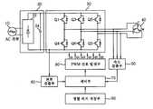
도 2는 본 발명의 일 실시 예에 따른 브러시리스 직류 모터 제어 장치의 블록 구성도,2 is a block diagram of a brushless DC motor control apparatus according to an embodiment of the present invention.
도 3은 본 발명의 일 실시 예에 따른 브러시리스 직류 모터의 정렬 제어 방법을 설명하기 위한 흐름도.3 is a flowchart illustrating a method of controlling alignment of a brushless DC motor according to an embodiment of the present invention.
본 발명은 브러시리스 직류(BrushLess Direct Current, 이하 "BLDC"라 함) 모터의 제어에 관한 것으로, 더욱 상세하게는 BLDC 모터의 초기 운전 시에 회전자의 위치를 강제 정렬하는 BLDC 모터의 정렬 제어 방법에 관한 것이다.BACKGROUND OF THE
현재 BLDC 모터는 냉장고 및 에어컨용 압축기와 세탁기 등과 같이 고효율 가변속 운전을 구현하는 것이 필요한 제품에 널리 사용되고 있다.Currently, BLDC motors are widely used in products requiring high-efficiency variable-speed operation such as refrigerators and air conditioner compressors and washing machines.
통상적으로 BLDC 모터의 고정자(stator)는 코일에 전류를 흘려 형성하는 전 기자(armature)를 사용하고, 회전자(rotator)는 N극과 S극이 반복되어 형성된 영구자석을 사용한다. BLDC 모터가 연속적으로 회전하기 위해서는 BLDC 모터의 연속적인 회전자계의 형성이 필요하며, 연속적인 회전자계를 형성하기 위해서는 전기자의 각 상의 코일에 흐르는 전류의 전환(commutation)을 적절한 시점에 해야 하는데, 적절한 전환을 위해서는 회전자의 위치를 정확히 인식해야 한다. 여기서 전환이란 회전자가 회전할 수 있도록 모터 고정자 코일의 전류 방향을 바꾸어 주는 것이다.Generally, a stator of a BLDC motor uses an armature that forms a current by flowing a current to a coil, and a rotator uses a permanent magnet formed by repeated N and S poles. In order for the BLDC motor to rotate continuously, it is necessary to form a continuous rotor system of the BLDC motor. In order to form a continuous rotor system, the commutation of the current flowing in the coil of each phase of the armature must be made at an appropriate point. For the conversion, the position of the rotor must be accurately recognized. The conversion here is to change the current direction of the motor stator coil so that the rotor can rotate.
BLDC 모터의 원활한 운전을 위해서는 회전자의 위치와 상 전류의 전환시점을 정밀하게 일치시켜야 하며, 이를 위해 회전자의 위치를 검출하기 위한 장치가 요구되는데, 일반적으로는 회전자의 위치 검출을 위해 홀센서(Hall sensor)나 리졸버(Resolver) 소자, 인코더(encoder)와 같은 위치검출센서를 이용하였다.In order to smoothly operate the BLDC motor, it is necessary to precisely match the position of the rotor and the switching point of the phase current. For this purpose, a device for detecting the position of the rotor is required. Generally, A position detection sensor such as a sensor (Hall sensor), a resolver device, or an encoder is used.
이러한 위치검출센서는 제조 원가가 비싸고, 압축기의 경우 압축기 내부의 온도 등 환경적인 문제로 인하여 사용할 수 없기 때문에 BLDC 모터의 전압, 전류정보 등을 이용하여 회전자의 위치를 간접적으로 검출하는 센서리스(sensorless) 제어가 모색되었다. 이렇게 위치검출센서 대신 전기회로를 이용하여 회전자의 위치를 검출하는 운전모드를 센서리스 운전모드라고 한다.Since such a position detection sensor is expensive to manufacture and can not be used due to environmental problems such as a temperature inside the compressor in the case of a compressor, it is not possible to use a sensorless sensor that indirectly detects the position of the rotor using the voltage and current information of the BLDC motor sensorless control was sought. The operation mode for detecting the position of the rotor by using an electric circuit instead of the position detection sensor is referred to as a sensorless operation mode.
한편, 센서리스 운전모드를 포함하는 BLDC 모터의 운전제어에 있어서 정지 중에는 회전자의 위치에 대한 정보가 파악되지 않기 때문에 센서리스 운전모드로 운전하기 이전에 강제적인 초기 기동 방법을 택하고 있다. 이는 초기 기동 시 BLDC 모터의 3상 권선들 중에서 임의의 2개의 상 권선에 전류를 일정시간동안 흘려 모터의 회전자 위치를 정렬시키는 것이다.On the other hand, in the operation control of the BLDC motor including the sensorless operation mode, since the information on the position of the rotor is not recognized during the stoppage, the forced initial start-up method is adopted before the operation in the sensorless operation mode. This is to align the rotor position of the motor by flowing current to any two phase windings of the three phase windings of the BLDC motor at the time of initial start up for a certain time.
도 1은 종래 기술에 따른 압축기 구동 모터의 기동제어 방법을 설명하기 위한 흐름도이다.1 is a flowchart for explaining a start control method of a compressor driving motor according to the related art.
먼저, BLDC 모터의 임의의 2상에 전류를 공급하여 회전자 위치를 강제로 정렬시키고(S1), 회전자의 정렬이 완료되면 BLDC 모터에 인가되는 전압의 크기와 주파수를 가변하여 BLDC 모터의 회전자를 일정속도까지 가속하여 강제로 회전시키고(S3), BLDC 모터의 고정자 권선으로부터 역기전력 검출이 가능한 속도까지 회전자의 회전속도가 도달하면 BLDC 모터에 인가되는 전압의 크기를 조절하여 회전자 자계와 고정자 자계의 위상을 조절한 후 센서리스 운전모드로 전환하며(S5), BLDC 모터의 역기전력 정보로부터 간접 검출된 회전자 위치정보를 이용하여 상 전환 및 속도제어를 하여 BLDC 모터를 운전한다(S7).First, a current is supplied to arbitrary two phases of the BLDC motor to forcibly align the rotor position (S1). When the alignment of the rotor is completed, the magnitude and frequency of the voltage applied to the BLDC motor are varied, When the rotational speed of the rotor reaches the speed at which the counter electromotive force can be detected from the stator winding of the BLDC motor, the magnitude of the voltage applied to the BLDC motor is adjusted, After the phase of the stator magnetic field is adjusted, the mode is switched to the sensorless operation mode (S5), and the BLDC motor is operated by phase switching and speed control using indirectly detected rotor position information from the counter electromotive force information of the BLDC motor (S7) .
그런데, BLDC 모터를 냉장고 또는 에어컨의 압축기를 구동하기 위해 압축기의 크랭크 축과 결합한 경우에, 압축기 구동 직후의 회전자 위치는 압축기의 가스토크에 의해 결정되는데, 압축 구간에서는 가스토크가 높아서 회전자가 곧바로 정지하나 토출 구간에서는 가스토크가 낮아서 회전자가 곧바로 정지하지 않으므로 회전자의 위치를 전혀 예상할 수가 없다.However, when the BLDC motor is combined with the crankshaft of the compressor for driving the compressor of the refrigerator or the air conditioner, the rotor position immediately after the compressor is driven is determined by the gas torque of the compressor. In the compression section, the gas torque is high, The position of the rotor can not be predicted at all because the gas torque is low in the discharge section and the rotor does not stop immediately.
아울러, 압축기가 구동 후에 정지하게 되면 압축기 정지 바로 직전의 상태에 따라 압축 상태나 토출 상태를 유지하는데, 이 상태에서 강제 정렬 후에 재 기동하게 되면, 압축기의 압축 구간에 회전자가 정렬된 상태이면 높은 기동토크가 요구되나 압축기의 토출 구간에 회전자가 강제 정렬된 상태이면 비교적 낮은 기동토크가 요구된다.When the compressor is stopped after the compressor is driven, the compression state or the discharge state is maintained according to the state just before the compressor stop. If the compressor is restarted after the forced alignment in this state, if the rotor is aligned in the compression section of the compressor, Torque is required but a relatively low starting torque is required if the rotor is forcedly aligned in the discharge section of the compressor.
따라서, 압축기의 토출 구간에 회전자가 강제 정렬된 상태이면 비교적 낮은 기동토크가 요구되어 문제가 되지 않으나 압축기의 압축 구간에 회전자가 정렬된 상태일 때는 높은 기동토크가 요구되어 전류가 과도하게 소요됨은 물론이고 구동 회로 및 모터에 악영향을 주게 되므로 비교적 낮은 기동토크가 요구되는 위치에 회전자를 강제 정렬할 필요가 있다.Accordingly, when the rotor is forcedly aligned in the discharge section of the compressor, relatively low starting torque is required, which is not a problem. However, when the rotor is aligned in the compression section of the compressor, a high starting torque is required, And adversely affects the drive circuit and the motor, it is necessary to forcibly align the rotor at a position where a relatively low starting torque is required.
이와 같이 BLDC 모터는 초기 기동 시에 수행하는 강제 정렬의 회전자 위치를 부하의 특성에 따라 결정할 필요가 있으나, 종래에는 강제 정렬 시에 회전자의 위치를 변경하거나 조절할 수가 없는 문제점이 있었다.In this way, the BLDC motor needs to determine the rotor position of the forced alignment performed at the time of initial startup according to the characteristics of the load, but conventionally, there has been a problem that the position of the rotor can not be changed or adjusted at the time of forced alignment.
본 발명은 이와 같은 종래의 문제점을 해결하기 위하여 제안한 것으로, BLDC 모터의 초기 운전 시에 기동토크를 기준으로 강제 정렬에 의한 최적의 회전자 위치를 추출하여 이후의 강제 정렬 시에는 기동토크가 비교적 낮은 최적의 위치로 회전자를 강제 정렬하는 BLDC 모터의 정렬 제어 방법을 제공하는 데 그 목적이 있다.SUMMARY OF THE INVENTION The present invention has been proposed in order to solve such a conventional problem, and it is an object of the present invention to extract an optimum rotor position by forced alignment based on a starting torque at the time of initial operation of a BLDC motor, And an object of the present invention is to provide an alignment control method of a BLDC motor for forcibly aligning a rotor to an optimum position.
이와 같은 목적을 실현하기 위한 본 발명에 따른 BLDC 모터의 정렬 제어 방법은, BLDC 모터의 초기 운전 시에 회전자를 특정 위치에 강제로 정렬하는 단계와, BLDC 모터의 회전자를 일정속도까지 가속하여 강제로 회전시키면서 기동 시의 소모 전류량에 의거하여 기동토크를 측정하는 단계와, 이전 단계를 통해 회전자의 위치를 강제로 정렬하는 강제 정렬 횟수를 카운트하는 단계와, 이전 단계에서 카운트한 강제 정렬 횟수와 기 설정된 기준 횟수를 비교한 결과에 의거하여 회전자의 강제 정렬 위치를 변경해 가면서 기준 횟수동안 이전 단계들을 반복하는 단계와, 기준횟수동안 강제 정렬 위치별로 측정된 기동토크를 비교하여 기 설정한 선택기준에 부합하는 기동토크를 가지는 강제 정렬 위치를 최적 강제 정렬 위치로 결정하여 이후의 강제 정렬 시에는 최적 강제 정렬 위치로 회전자를 정렬하는 단계를 포함한다.In order to achieve the above object, there is provided a method of controlling alignment of a BLDC motor, comprising: aligning a rotor to a specific position during an initial operation of the BLDC motor; and accelerating the rotor of the BLDC motor to a predetermined speed A step of counting the number of forced alignments for forcibly aligning the positions of the rotors through a previous step; a step of counting the number of forcible alignments counted in the previous step Repeating the previous steps for the reference number of times while changing the forced alignment position of the rotor based on the result of comparing the number of times of the preset reference and the preset reference number, The forcible alignment position having the starting torque conforming to the standard is determined as the optimum forced alignment position, and in the subsequent forced alignment, And aligning the rotor to an optimal forced alignment position.
이하, 본 발명의 바람직한 실시 예를 첨부된 도면들을 참조하여 상세히 설명한다. 아울러 본 발명을 설명함에 있어, 관련된 공지 구성 또는 기능에 대한 구체적인 설명이 본 발명의 요지를 흐릴 수 있다고 판단되는 경우에는 그 상세한 설명을 생략한다.Hereinafter, preferred embodiments of the present invention will be described in detail with reference to the accompanying drawings. In the following description of the present invention, detailed description of known functions and configurations incorporated herein will be omitted when it may make the subject matter of the present invention rather unclear.
도 2는 본 발명의 일 실시 예에 따른 BLDC 모터 제어 장치의 블록 구성도이다.2 is a block diagram of a BLDC motor control apparatus according to an embodiment of the present invention.
도 2에 도시한 바와 같이 본 발명을 위한 모터 제어 장치는, 상용교류전원이 입력되는 전원부(10)와, 전원부(10)로부터 입력되는 AC전원을 DC전원으로 변환하는 정류기(22)와 평활 콘덴서(24)를 포함하는 정류부(20)와, BLDC 모터(40)를 회전시키기 위해 다수의 파워 트랜지스터(Q1∼Q6)를 교번으로 턴온 또는 턴오프시켜 정류부(20)로부터 출력되는 DC전원을 3상(U, V, W) AC전원으로 변환하는 인버터(Inverter)부(30)와, BLDC 모터(40)의 역기전력을 감지하여 검출한 회전자 위치신호에 기초하여 BLDC 모터(40)의 회전 속도를 검출하는 속도 검출부(50)와, 정류부(30)와 인버터부(30) 사이의 전류를 검출하는 전류 검출부(60)와, 전류 검출 부(60)에서 검출한 전류정보와 속도 검출부(50)에서 검출한 회전 속도를 이용하여 BLDC 모터(40)의 회전 속도를 제어하기 위한 제어신호를 제공하되 초기 운전 시에 기동토크를 기준으로 강제 정렬에 의한 최적의 회전자 위치를 추출하여 이후의 강제 정렬 시에는 기동토크가 높지 않은 최적의 위치로 회전자를 강제 정렬하는 제어부(70)와, 제어부(70)의 제어신호에 따라 PWM 신호를 발생시켜 인버터부(30)내 파워 트랜지스터들을 턴온 또는 턴오프(스위칭)시키는 PWM 신호 발생부(80)와, 제어부(70)에서 추출한 최적의 회전자 위치를 위한 강제 정렬 상전환 패턴이 저장된 정렬 위치 저장부(90)를 포함하여 구성된다.2, the motor control apparatus according to the present invention includes a
특히, 제어부(70)는 PWM 신호 발생부(80)를 통해 인버터부(30)의 스위칭 동작을 제어하여 BLDC 모터(40)의 회전 구동을 제어함에 있어서 도 3의 흐름도와 같이, 초기 운전 시에 기동토크를 기준으로 강제 정렬에 의한 최적의 회전자 위치를 위한 강제 정렬 상전환 패턴 정보를 정렬 위치 저장부(90)에 저장하며, 이후의 강제 정렬 시에는 정렬 위치 저장부(90)에 저장된 강제 정렬 상전환 패턴 정보에 의거하여 기동토크가 비교적 낮은 최적의 위치로 회전자를 강제 정렬한다.3, the
도 3은 본 발명의 일 실시 예에 따른 브러시리스 직류 모터의 정렬 제어 방법을 설명하기 위한 흐름도이다.3 is a flowchart illustrating a method of controlling alignment of a brushless DC motor according to an embodiment of the present invention.
도 3에 나타낸 바와 같이 본 발명의 정렬 제어 방법은, BLDC 모터의 초기 운전 시에 3상 중에서 특정의 2상에 전류를 공급하여 회전자 위치를 강제로 정렬하는 단계(S101)와, 회전자의 정렬이 완료되면 BLDC 모터에 인가되는 전압의 크기와 주 파수를 가변하여 BLDC 모터의 회전자를 일정속도까지 가속하여 강제로 회전시키면서 기동 시의 소모 전류량에 의거하여 기동토크를 측정하는 단계(S103)와, 회전자 위치를 강제로 정렬하는 강제 정렬 횟수를 카운트하는 단계(S105)와, 카운트한 강제 정렬 횟수와 기 설정된 기준 횟수를 비교하는 단계(S107)와, 카운트한 강제 정렬 횟수가 기 설정된 기준 횟수미만이면 정렬 위치를 변경하여 회전자 위치를 강제로 정렬한 후에 이후의 절차를 재수행하는 단계(S109)와, 카운트한 강제 정렬 횟수가 기 설정된 기준 횟수이상이면 강제 정렬 위치별로 측정된 기동토크를 비교하여 기 설정된 선택기준에 부합하는 기동토크를 가지는 강제 정렬 위치를 최적의 강제 정렬 위치로 결정하여 이후의 강제 정렬 시에는 최적의 강제 정렬 위치로 회전자를 정렬하도록 하는 단계(S111)를 포함하여 구성된다.As shown in FIG. 3, the alignment control method of the present invention includes the steps of: (S101) forcibly aligning a rotor position by supplying a current to two specific phases among three phases during an initial operation of the BLDC motor; A step S103 of measuring the starting torque based on the amount of consumed current during starting by varying the magnitude and frequency of the voltage applied to the BLDC motor to accelerate the rotor of the BLDC motor to a predetermined speed and forcibly rotating the BLDC motor, A step S105 of counting the number of forced alignments for forcibly aligning the rotor positions, a step S107 of comparing the number of mandatory alignments counted and a preset reference number, If the counted number of forced alignments is less than the predetermined number of times (S109), the step of repeating the following procedure after forcibly aligning the rotor position by changing the alignment position is performed The forced alignment position having the starting torque corresponding to the preset selection criterion is determined as the optimum forced alignment position by comparing the starting torque measured for each alignment position and the rotor is aligned to the optimal forced alignment position for the subsequent forced alignment (S111).
이와 같이 구성된 본 발명의 정렬 제어 방법이 도 2의 모터 제어 장치에 의해 수행되는 과정을 도 2 및 도 3을 참조하여 설명하기로 한다. 이하의 설명에서는 본 발명의 요지인 BLDC 모터의 최적 정렬 위치를 결정하는 과정에 대한 이해를 돕기 위하여 BLDC 모터의 일반적인 제어 과정에 대한 설명을 생략하기로 한다.The process of the alignment control method according to the present invention constructed as described above by the motor control apparatus of FIG. 2 will be described with reference to FIGS. 2 and 3. FIG. In the following description, a description of a general control process of the BLDC motor will be omitted to help understand the process of determining the optimum alignment position of the BLDC motor, which is a gist of the present invention.
먼저, 제어부(70)는 BLDC 모터(40)의 초기 운전 시에 3상 중에서 특정의 2상에 전류를 공급하여 회전자 위치를 강제로 정렬하도록 제어신호를 출력한다. 그러면 PWM 신호 발생부(80)는 제어부(70)의 제어신호에 따라 PWM 신호를 발생시켜 인버터부(30)내 파워 트랜지스터들을 턴온 또는 턴오프(스위칭)시키며, BLDC 모 터(40)의 3상 중에서 특정의 2상에 전류가 공급되어 회전자의 위치가 강제로 정렬된다(S101).First, the
여기서, BLDC 모터(40)의 3상에 전류를 공급할 때에 각 상에 흐르는 전류의 패턴은 U+V-, U+W-, V+W-, V+U-, W+U-, W+V-로 나타난다. 예를 들어 U+V-의 상전환 패턴은 U상으로부터 V상으로 전류가 흐르게 하는 것을 의미하고, U+W-의 상전환 패턴은 U상으로부터 W상으로 전류가 흐르게 하는 것을 의미한다. 즉, 단계 S101에서 BLDC 모터(40)에는 U+V-, U+W-, V+W-, V+U-, W+U-, W+V- 중에서 어느 하나의 상전환 패턴으로 전류가 공급되어 회전자의 위치가 강제로 정렬된다.When the current is supplied to the three phases of the
이후, 제어부(70)는 BLDC 모터(40)에 인가되는 전압의 크기와 주파수를 가변하여 BLDC 모터(40)의 회전자를 일정속도까지 가속하여 강제로 회전시키며, 전류 검출부(60)는 기동토크의 측정을 위해 정류부(30)와 인버터부(30) 사이의 전류를 검출하여 제어부(70)로 제공한다(S103). 한편, 이와 같이 BLDC 모터(40)를 동기 가속하는 과정은 종래 기술에서 설명한 도 1의 단계 S3에 해당하며, 이하에서는 설명을 생략하겠지만 본 발명에 의한 최적 정렬 위치 결정 과정과는 별도로 도 1의 단계 S5와 단계 S7이 순차로 수행된다.Thereafter, the
아울러, 제어부(70)는 단계 S101에 의한 강제 정렬 횟수를 카운트하며(S105), 카운트한 강제 정렬 횟수와 기 설정된 기준 횟수를 비교한다(S107).In addition, the
만약, 카운트한 강제 정렬 횟수가 기 설정된 기준 횟수미만이면 이후에 단계 S101을 재수행할 때에 강제로 정렬할 회전자 위치를 변경한다(S109). 여기서 BLDC 모터(40)의 초기 운전 시에는 단계 S107의 이후에 단계 S109를 수행하게 될 것이 자명하다. 그런데, 단계 S101을 재수행하게 될 시점은 실시 예에 따라 변화될 수 있다. 즉 BLDC 모터(40)의 초기 운전 시에 본 발명에 의한 최적 정렬 위치 결정 과정을 종료한 후에 일반적인 운전을 수행하도록 실시한 경우라면 단계 S109 이후에 곧바로 단계 S101이 재수행될 것이나, 일반적인 운전을 수행하는 중에 본 발명에 의한 최적 정렬 위치 결정 과정을 수행하도록 실시한 경우라면 단계 S109를 완료한 이후라도 곧바로 단계 S101을 재수행하지 않고 BLDC 모터(40)가 정지 후에 다시 기동할 때에 수행하게 된다.If the counted number of forced alignments is less than the preset reference number, the position of the rotor to be forcedly aligned is changed (S109). Here, at the initial operation of the
이와 같이 단계 S101이 재수행되면 BLDC 모터(40)에는 바뀐 상전환 패턴으로 전류가 공급되어 회전자가 다른 위치로 강제 정렬된다. 예로서 최초 수행한 단계 S101에서 U+V- 상전환 패턴으로 전류가 공급되었다면 단계 S101이 재수행될 때에는 V+W- 상전환 패턴으로 전류가 공급된다.When the step S101 is performed again, the
이후, 단계 S103 내지 단계 S107이 재수행되는데, 단계 S105에 의해 카운트한 강제 정렬 횟수가 기 설정된 기준 횟수이상일 때까지 단계 S101 내지 단계 S107을 재수행한다. 여기서, 기준 횟수는 BLDC 모터(40)의 회전자가 강제 정렬 가능한 모든 위치에 적어도 1회 이상 정렬되도록 설정한다. 예로서 각각의 상전환 패턴마다 강제 정렬 위치가 모두 다른 경우라면 3상에 의한 모든 상전환 패턴인 6회로 설정하며, 일부 상전환 패턴에 의한 강제 정렬 위치가 동일하다면 그 이하의 횟수로 설정한다.Thereafter, steps S103 to S107 are performed again. Steps S101 to S107 are repeated until the number of forced alignments counted in step S105 is equal to or greater than a predetermined reference number. Here, the reference number is set so that the rotor of the
한편, 제어부(70)는 단계 S107에서 카운트한 강제 정렬 횟수가 기 설정된 기준 횟수이상이면, 단계 S103에서 전류 검출부(60)로부터 제공되는 전류 검출값들을 비교하여 기 설정된 선택기준에 부합하는 전류 검출값을 선택한다. 여기서, 기 설정된 기준은 중간값으로 설정하는 것이 바람직하다. 즉 중간값을 가지는 기동토크를 선택하여 이에 대응하는 상전환 패턴을 최적의 강제 정렬 위치로 결정한다(S111). 여기서 중간값을 선택하는 이유는 BLDC 모터(40)를 냉장고 또는 에어컨의 압축기를 구동하기 위해 압축기의 크랭크 축과 결합한 경우에 BLDC 모터(40)의 1회전에 크랭크 축이 왕복운동하도록 결합하는 것이 일반적인 결합 방식인 점 등을 고려하여 어떠한 경우라도 최대 기동토크 구간이 회피되도록 하기 위함이다.On the other hand, if the number of forced alignments counted in step S107 is equal to or greater than the predetermined reference number, the
다음으로, 제어부(70)는 단계 S111에서 결정된 강제 정렬 상전환 패턴을 정렬 위치 저장부(90)에 저장하며, 이후의 강제 정렬 시에는 정렬 위치 저장부(90)에 기 저장한 강제 정렬 상전환 패턴에 의거하여 기동토크가 높지 않은 최적의 위치로 회전자를 강제 정렬한다.Next, the
앞서 설명한 실시 예에서는 회전자 강제 정렬 시에 BLDC 모터(40)의 3상 중에서 특정의 2상에 전류를 공급하였으나 3상에 전류를 공급할 수도 있다. 예로서 U+V-의 상전환 패턴을 U+V-W-의 상전환 패턴으로 변경할 수도 있다. 즉 U상으로부터 V상 및 W상으로 전류가 흐르도록 제어하는 것이다. 이와 같이 W상에 추가적으로 음(-)전위를 걸어주면 V상에만 음(-)전위를 걸어줄 때보다 더 빠른 속도로 회전자가 정렬된다.In the above-described embodiment, a current is supplied to two specific phases among the three phases of the
또한, 앞서 설명한 실시 예에서는 회전자 강제 정렬을 한번에 수행하는 것을 예시하였으나 복수회에 걸쳐 수행할 수도 있다. 예로서 1차 강제 정렬과 2차 강제 정렬로 나누어서 1차 강제 정렬 시에는 3상 모두에 전류를 공급(예로서 U+V-W-의 상전환 패턴)하고 2차 강제 정렬 시에는 2상에 전류를 공급(예로서 U+V-의 상전환 패턴)하여 1차 강제 정렬 시에 미처 요망하는 위치에 회전자가 정렬되지 않았을 경우를 대비할 수도 있다.Also, in the above-described embodiment, the rotor forced alignment is performed at one time, but it may also be performed a plurality of times. For example, when the first forced alignment is divided into the first forced alignment and the second forced alignment, current is supplied to all three phases (for example, the phase change pattern of U + VW-) It is possible to prepare for the case where the rotor is not aligned at a desired position at the time of the first forced alignment by supplying (for example, U + V- phase change pattern).
지금까지 본 발명의 일 실시 예에 국한하여 설명하였으나 본 발명의 기술이 당업자에 의하여 용이하게 변형 실시될 가능성이 자명하다. 이러한 변형된 실시 예들은 본 발명의 특허청구범위에 기재된 기술사상에 포함된다고 하여야 할 것이다.While the present invention has been particularly shown and described with reference to exemplary embodiments thereof, it is to be understood that the invention is not limited to the disclosed exemplary embodiments. It is to be understood that these modified embodiments are included in the technical idea described in the claims of the present invention.
전술한 바와 같이 본 발명은 BLDC 모터의 초기 운전 시에 기동토크를 기준으로 강제 정렬에 의한 최적의 회전자 위치를 추출하여 이후의 강제 정렬 시에는 기동토크가 비교적 낮은 최적의 위치로 회전자를 강제 정렬함으로써, 모터의 구동 시에 비교적 낮은 기동토크가 요구되어 과도한 전류 소모를 방지함과 아울러 구동 회로 및 모터에 악영향을 주는 요소를 제거하여 구동 회로 및 모터를 보호하는 효과가 있다.As described above, the present invention extracts the optimum rotor position by forced alignment on the basis of the starting torque at the time of initial operation of the BLDC motor, and forcibly aligns the rotor to the optimum position where the starting torque is relatively low A relatively low starting torque is required at the time of driving the motor to prevent excessive current consumption, and the elements that adversely affect the driving circuit and the motor are removed to protect the driving circuit and the motor.
Claims (6)
Translated fromKoreanPriority Applications (1)
| Application Number | Priority Date | Filing Date | Title |
|---|---|---|---|
| KR1020070038105AKR100847454B1 (en) | 2007-04-19 | 2007-04-19 | Method of alignment control of brushless DC motor |
Applications Claiming Priority (1)
| Application Number | Priority Date | Filing Date | Title |
|---|---|---|---|
| KR1020070038105AKR100847454B1 (en) | 2007-04-19 | 2007-04-19 | Method of alignment control of brushless DC motor |
Publications (1)
| Publication Number | Publication Date |
|---|---|
| KR100847454B1true KR100847454B1 (en) | 2008-07-21 |
Family
ID=39824895
Family Applications (1)
| Application Number | Title | Priority Date | Filing Date |
|---|---|---|---|
| KR1020070038105AExpired - Fee RelatedKR100847454B1 (en) | 2007-04-19 | 2007-04-19 | Method of alignment control of brushless DC motor |
Country Status (1)
| Country | Link |
|---|---|
| KR (1) | KR100847454B1 (en) |
Cited By (3)
| Publication number | Priority date | Publication date | Assignee | Title |
|---|---|---|---|---|
| KR101462736B1 (en)* | 2012-12-27 | 2014-11-17 | 삼성전기주식회사 | Bldc motor drive device and controlling method thereof |
| KR20170061234A (en)* | 2015-11-25 | 2017-06-05 | 학교법인 두원학원 | Controlling apparatus for motor and method thereof |
| CN106817050A (en)* | 2015-09-22 | 2017-06-09 | 韩国自动车部品株式会社 | The drive control method of Brushless DC motor |
Citations (4)
| Publication number | Priority date | Publication date | Assignee | Title |
|---|---|---|---|---|
| JPH0787779A (en)* | 1993-06-22 | 1995-03-31 | Sankyo Seiki Mfg Co Ltd | Drive circuit of brushless motor |
| KR20010100648A (en)* | 2000-05-04 | 2001-11-14 | 구자홍 | Method for aligning position of a rotator of a SRM(switched reluctance motor) and SRM driving circuit for realizing the method |
| KR20060070911A (en)* | 2004-12-21 | 2006-06-26 | 삼성전자주식회사 | Starting device and method of BCD motor |
| JP2007046544A (en) | 2005-08-10 | 2007-02-22 | Mitsubishi Heavy Ind Ltd | Controller for electric compressor |
- 2007
- 2007-04-19KRKR1020070038105Apatent/KR100847454B1/ennot_activeExpired - Fee Related
Patent Citations (4)
| Publication number | Priority date | Publication date | Assignee | Title |
|---|---|---|---|---|
| JPH0787779A (en)* | 1993-06-22 | 1995-03-31 | Sankyo Seiki Mfg Co Ltd | Drive circuit of brushless motor |
| KR20010100648A (en)* | 2000-05-04 | 2001-11-14 | 구자홍 | Method for aligning position of a rotator of a SRM(switched reluctance motor) and SRM driving circuit for realizing the method |
| KR20060070911A (en)* | 2004-12-21 | 2006-06-26 | 삼성전자주식회사 | Starting device and method of BCD motor |
| JP2007046544A (en) | 2005-08-10 | 2007-02-22 | Mitsubishi Heavy Ind Ltd | Controller for electric compressor |
Cited By (7)
| Publication number | Priority date | Publication date | Assignee | Title |
|---|---|---|---|---|
| KR101462736B1 (en)* | 2012-12-27 | 2014-11-17 | 삼성전기주식회사 | Bldc motor drive device and controlling method thereof |
| CN106817050A (en)* | 2015-09-22 | 2017-06-09 | 韩国自动车部品株式会社 | The drive control method of Brushless DC motor |
| KR101755244B1 (en)* | 2015-09-22 | 2017-07-10 | 주식회사 코아비스 | Driving control method for BLDC motor |
| CN106817050B (en)* | 2015-09-22 | 2019-05-10 | 韩国自动车部品株式会社 | The drive control method of Brushless DC motor |
| US10483883B2 (en) | 2015-09-22 | 2019-11-19 | Coavis | Driving control method for BLDC motor |
| KR20170061234A (en)* | 2015-11-25 | 2017-06-05 | 학교법인 두원학원 | Controlling apparatus for motor and method thereof |
| KR102512497B1 (en)* | 2015-11-25 | 2023-03-23 | 학교법인 두원학원 | Controlling apparatus for motor and method thereof |
Similar Documents
| Publication | Publication Date | Title |
|---|---|---|
| US9998059B2 (en) | Motor driving apparatus | |
| EP2219289B1 (en) | Inverter device for washing machine | |
| KR101041076B1 (en) | Starting control method of brushless DC motor | |
| KR100447559B1 (en) | Starting control method of and control apparatus for synchronous motor, and air conditioner, refrigerator, washing machine and vacuum cleaner each provided with the control apparatus | |
| US8242725B2 (en) | Method for operating sensorless and brushless motors | |
| CN101512893B (en) | For starting and controlling the method for synchronous motor and corresponding control circuit | |
| US7427841B2 (en) | Driving method and driver of brushless DC motor | |
| JP4167232B2 (en) | Brushless DC motor control method | |
| US7391174B2 (en) | Brushless DC motor control apparatus and control method thereof | |
| EP1739822A1 (en) | Three phase BLDC motor controller and control method thereof | |
| KR100859077B1 (en) | Start control method of compressor drive motor | |
| KR100847454B1 (en) | Method of alignment control of brushless DC motor | |
| KR20060075262A (en) | Phase change method of BLC motor | |
| KR101224635B1 (en) | Method and appartus for diagnosising short of motor driving system | |
| KR20100071692A (en) | Control method of bldc motor | |
| JP2001008490A (en) | Controller and control method for permanent magnet synchronous motor | |
| JP4531180B2 (en) | Synchronous motor and method for starting synchronous motor | |
| JP3711749B2 (en) | Permanent magnet type synchronous motor and control method thereof | |
| KR100677876B1 (en) | Alignment control method of brushless DC motor | |
| JP5056106B2 (en) | Inverter control device for motor drive and equipment using the device | |
| JP2004222382A (en) | Apparatus and method for controlling operation of motor | |
| KR100811659B1 (en) | Starting Control Method of Compressor Including Brushless DC Motor | |
| US20250253783A1 (en) | Method for Detecting Field Magnet Position of an Electric Motor | |
| KR20080094122A (en) | How to Control Sensorless ZLDC Motors | |
| KR20250057439A (en) | Apparatus for driving motor, method for controlling same, and electronic device driven by same |
Legal Events
| Date | Code | Title | Description |
|---|---|---|---|
| A201 | Request for examination | ||
| PA0109 | Patent application | St.27 status event code:A-0-1-A10-A12-nap-PA0109 | |
| PA0201 | Request for examination | St.27 status event code:A-1-2-D10-D11-exm-PA0201 | |
| D13-X000 | Search requested | St.27 status event code:A-1-2-D10-D13-srh-X000 | |
| D14-X000 | Search report completed | St.27 status event code:A-1-2-D10-D14-srh-X000 | |
| E701 | Decision to grant or registration of patent right | ||
| PE0701 | Decision of registration | St.27 status event code:A-1-2-D10-D22-exm-PE0701 | |
| GRNT | Written decision to grant | ||
| PR0701 | Registration of establishment | St.27 status event code:A-2-4-F10-F11-exm-PR0701 | |
| PR1002 | Payment of registration fee | St.27 status event code:A-2-2-U10-U11-oth-PR1002 Fee payment year number:1 | |
| PG1601 | Publication of registration | St.27 status event code:A-4-4-Q10-Q13-nap-PG1601 | |
| R18-X000 | Changes to party contact information recorded | St.27 status event code:A-5-5-R10-R18-oth-X000 | |
| PN2301 | Change of applicant | St.27 status event code:A-5-5-R10-R11-asn-PN2301 | |
| PN2301 | Change of applicant | St.27 status event code:A-5-5-R10-R14-asn-PN2301 | |
| PR1001 | Payment of annual fee | St.27 status event code:A-4-4-U10-U11-oth-PR1001 Fee payment year number:4 | |
| PR1001 | Payment of annual fee | St.27 status event code:A-4-4-U10-U11-oth-PR1001 Fee payment year number:5 | |
| PN2301 | Change of applicant | St.27 status event code:A-5-5-R10-R13-asn-PN2301 St.27 status event code:A-5-5-R10-R11-asn-PN2301 | |
| PN2301 | Change of applicant | St.27 status event code:A-5-5-R10-R13-asn-PN2301 St.27 status event code:A-5-5-R10-R11-asn-PN2301 | |
| FPAY | Annual fee payment | Payment date:20130702 Year of fee payment:6 | |
| PR1001 | Payment of annual fee | St.27 status event code:A-4-4-U10-U11-oth-PR1001 Fee payment year number:6 | |
| R18-X000 | Changes to party contact information recorded | St.27 status event code:A-5-5-R10-R18-oth-X000 | |
| FPAY | Annual fee payment | Payment date:20140626 Year of fee payment:7 | |
| PR1001 | Payment of annual fee | St.27 status event code:A-4-4-U10-U11-oth-PR1001 Fee payment year number:7 | |
| FPAY | Annual fee payment | Payment date:20150604 Year of fee payment:8 | |
| PR1001 | Payment of annual fee | St.27 status event code:A-4-4-U10-U11-oth-PR1001 Fee payment year number:8 | |
| FPAY | Annual fee payment | Payment date:20160712 Year of fee payment:9 | |
| PR1001 | Payment of annual fee | St.27 status event code:A-4-4-U10-U11-oth-PR1001 Fee payment year number:9 | |
| P22-X000 | Classification modified | St.27 status event code:A-4-4-P10-P22-nap-X000 | |
| R18-X000 | Changes to party contact information recorded | St.27 status event code:A-5-5-R10-R18-oth-X000 | |
| FPAY | Annual fee payment | Payment date:20170614 Year of fee payment:10 | |
| PR1001 | Payment of annual fee | St.27 status event code:A-4-4-U10-U11-oth-PR1001 Fee payment year number:10 | |
| R18-X000 | Changes to party contact information recorded | St.27 status event code:A-5-5-R10-R18-oth-X000 | |
| FPAY | Annual fee payment | Payment date:20180612 Year of fee payment:11 | |
| PR1001 | Payment of annual fee | St.27 status event code:A-4-4-U10-U11-oth-PR1001 Fee payment year number:11 | |
| R18-X000 | Changes to party contact information recorded | St.27 status event code:A-5-5-R10-R18-oth-X000 | |
| FPAY | Annual fee payment | Payment date:20190423 Year of fee payment:12 | |
| PR1001 | Payment of annual fee | St.27 status event code:A-4-4-U10-U11-oth-PR1001 Fee payment year number:12 | |
| PN2301 | Change of applicant | St.27 status event code:A-5-5-R10-R13-asn-PN2301 St.27 status event code:A-5-5-R10-R11-asn-PN2301 | |
| PC1903 | Unpaid annual fee | St.27 status event code:A-4-4-U10-U13-oth-PC1903 Not in force date:20200716 Payment event data comment text:Termination Category : DEFAULT_OF_REGISTRATION_FEE | |
| PN2301 | Change of applicant | St.27 status event code:A-5-5-R10-R13-asn-PN2301 St.27 status event code:A-5-5-R10-R11-asn-PN2301 | |
| PC1903 | Unpaid annual fee | St.27 status event code:N-4-6-H10-H13-oth-PC1903 Ip right cessation event data comment text:Termination Category : DEFAULT_OF_REGISTRATION_FEE Not in force date:20200716 |