KR100846245B1 - Monitor device, base device and information terminal device - Google Patents
Monitor device, base device and information terminal deviceDownload PDFInfo
- Publication number
- KR100846245B1 KR100846245B1KR1020027009740AKR20027009740AKR100846245B1KR 100846245 B1KR100846245 B1KR 100846245B1KR 1020027009740 AKR1020027009740 AKR 1020027009740AKR 20027009740 AKR20027009740 AKR 20027009740AKR 100846245 B1KR100846245 B1KR 100846245B1
- Authority
- KR
- South Korea
- Prior art keywords
- battery
- base
- monitor
- monitor device
- radiation pattern
- Prior art date
- Legal status (The legal status is an assumption and is not a legal conclusion. Google has not performed a legal analysis and makes no representation as to the accuracy of the status listed.)
- Expired - Fee Related
Links
Images


Classifications
- G—PHYSICS
- G06—COMPUTING OR CALCULATING; COUNTING
- G06F—ELECTRIC DIGITAL DATA PROCESSING
- G06F1/00—Details not covered by groups G06F3/00 - G06F13/00 and G06F21/00
- G06F1/16—Constructional details or arrangements
- G06F1/1613—Constructional details or arrangements for portable computers
- G06F1/1633—Constructional details or arrangements of portable computers not specific to the type of enclosures covered by groups G06F1/1615 - G06F1/1626
- G06F1/1684—Constructional details or arrangements related to integrated I/O peripherals not covered by groups G06F1/1635 - G06F1/1675
- G06F1/1698—Constructional details or arrangements related to integrated I/O peripherals not covered by groups G06F1/1635 - G06F1/1675 the I/O peripheral being a sending/receiving arrangement to establish a cordless communication link, e.g. radio or infrared link, integrated cellular phone
- H—ELECTRICITY
- H04—ELECTRIC COMMUNICATION TECHNIQUE
- H04N—PICTORIAL COMMUNICATION, e.g. TELEVISION
- H04N5/00—Details of television systems
- H04N5/64—Constructional details of receivers, e.g. cabinets or dust covers
- G—PHYSICS
- G06—COMPUTING OR CALCULATING; COUNTING
- G06F—ELECTRIC DIGITAL DATA PROCESSING
- G06F1/00—Details not covered by groups G06F3/00 - G06F13/00 and G06F21/00
- G06F1/16—Constructional details or arrangements
- G—PHYSICS
- G06—COMPUTING OR CALCULATING; COUNTING
- G06F—ELECTRIC DIGITAL DATA PROCESSING
- G06F1/00—Details not covered by groups G06F3/00 - G06F13/00 and G06F21/00
- G06F1/16—Constructional details or arrangements
- G06F1/1601—Constructional details related to the housing of computer displays, e.g. of CRT monitors, of flat displays
- G—PHYSICS
- G06—COMPUTING OR CALCULATING; COUNTING
- G06F—ELECTRIC DIGITAL DATA PROCESSING
- G06F1/00—Details not covered by groups G06F3/00 - G06F13/00 and G06F21/00
- G06F1/16—Constructional details or arrangements
- G06F1/1613—Constructional details or arrangements for portable computers
- G—PHYSICS
- G06—COMPUTING OR CALCULATING; COUNTING
- G06F—ELECTRIC DIGITAL DATA PROCESSING
- G06F1/00—Details not covered by groups G06F3/00 - G06F13/00 and G06F21/00
- G06F1/16—Constructional details or arrangements
- G06F1/1613—Constructional details or arrangements for portable computers
- G06F1/1626—Constructional details or arrangements for portable computers with a single-body enclosure integrating a flat display, e.g. Personal Digital Assistants [PDAs]
- G—PHYSICS
- G06—COMPUTING OR CALCULATING; COUNTING
- G06F—ELECTRIC DIGITAL DATA PROCESSING
- G06F1/00—Details not covered by groups G06F3/00 - G06F13/00 and G06F21/00
- G06F1/16—Constructional details or arrangements
- G06F1/1613—Constructional details or arrangements for portable computers
- G06F1/1632—External expansion units, e.g. docking stations
- G—PHYSICS
- G06—COMPUTING OR CALCULATING; COUNTING
- G06F—ELECTRIC DIGITAL DATA PROCESSING
- G06F1/00—Details not covered by groups G06F3/00 - G06F13/00 and G06F21/00
- G06F1/16—Constructional details or arrangements
- G06F1/1613—Constructional details or arrangements for portable computers
- G06F1/1633—Constructional details or arrangements of portable computers not specific to the type of enclosures covered by groups G06F1/1615 - G06F1/1626
- G06F1/1635—Details related to the integration of battery packs and other power supplies such as fuel cells or integrated AC adapter
- G—PHYSICS
- G06—COMPUTING OR CALCULATING; COUNTING
- G06F—ELECTRIC DIGITAL DATA PROCESSING
- G06F1/00—Details not covered by groups G06F3/00 - G06F13/00 and G06F21/00
- G06F1/16—Constructional details or arrangements
- G06F1/1613—Constructional details or arrangements for portable computers
- G06F1/1633—Constructional details or arrangements of portable computers not specific to the type of enclosures covered by groups G06F1/1615 - G06F1/1626
- G06F1/1637—Details related to the display arrangement, including those related to the mounting of the display in the housing
- G06F1/1654—Details related to the display arrangement, including those related to the mounting of the display in the housing the display being detachable, e.g. for remote use
- H—ELECTRICITY
- H02—GENERATION; CONVERSION OR DISTRIBUTION OF ELECTRIC POWER
- H02J—CIRCUIT ARRANGEMENTS OR SYSTEMS FOR SUPPLYING OR DISTRIBUTING ELECTRIC POWER; SYSTEMS FOR STORING ELECTRIC ENERGY
- H02J7/00—Circuit arrangements for charging or depolarising batteries or for supplying loads from batteries
- H02J7/0042—Circuit arrangements for charging or depolarising batteries or for supplying loads from batteries characterised by the mechanical construction
- H02J7/0044—Circuit arrangements for charging or depolarising batteries or for supplying loads from batteries characterised by the mechanical construction specially adapted for holding portable devices containing batteries
- G—PHYSICS
- G06—COMPUTING OR CALCULATING; COUNTING
- G06F—ELECTRIC DIGITAL DATA PROCESSING
- G06F2200/00—Indexing scheme relating to G06F1/04 - G06F1/32
- G06F2200/16—Indexing scheme relating to G06F1/16 - G06F1/18
- G06F2200/161—Indexing scheme relating to constructional details of the monitor
- G06F2200/1612—Flat panel monitor
- G—PHYSICS
- G06—COMPUTING OR CALCULATING; COUNTING
- G06F—ELECTRIC DIGITAL DATA PROCESSING
- G06F2200/00—Indexing scheme relating to G06F1/04 - G06F1/32
- G06F2200/16—Indexing scheme relating to G06F1/16 - G06F1/18
- G06F2200/163—Indexing scheme relating to constructional details of the computer
- G06F2200/1631—Panel PC, e.g. single housing hosting PC and display panel
- G—PHYSICS
- G06—COMPUTING OR CALCULATING; COUNTING
- G06F—ELECTRIC DIGITAL DATA PROCESSING
- G06F2200/00—Indexing scheme relating to G06F1/04 - G06F1/32
- G06F2200/16—Indexing scheme relating to G06F1/16 - G06F1/18
- G06F2200/163—Indexing scheme relating to constructional details of the computer
- G06F2200/1632—Pen holder integrated in the computer
Landscapes
- Engineering & Computer Science (AREA)
- Theoretical Computer Science (AREA)
- Computer Hardware Design (AREA)
- General Engineering & Computer Science (AREA)
- Physics & Mathematics (AREA)
- General Physics & Mathematics (AREA)
- Human Computer Interaction (AREA)
- Power Engineering (AREA)
- Multimedia (AREA)
- Signal Processing (AREA)
- Charge And Discharge Circuits For Batteries Or The Like (AREA)
- Devices For Indicating Variable Information By Combining Individual Elements (AREA)
- Secondary Cells (AREA)
Abstract
Translated fromKoreanDescription
Translated fromKorean본 발명은, LCD(액정 디스플레이) 등의 디스플레이를 구비하고, 배터리로 구동되는 모니터 장치, 이 모니터 장치에 화상 정보를 송신하는 베이스 장치 및 LCD 등의 디스플레이를 구비하고, 배터리로 구동되는 정보 단말 장치에 관한 것이다.The present invention includes a display device such as an LCD (liquid crystal display), a battery-driven monitor device, a base device for transmitting image information to the monitor device, and a display such as an LCD, and a battery-powered information terminal device. It is about.
주택 내부 등의 한정된 영역 내에서 구축되는 무선 LAN(Local Area Network) 시스템의 일종으로서, 출원인은 텔레비전 방송의 수신용 튜너가 내장 또는 접속되고, 모뎀을 통해 전화 회선이 접속되는 등, 정보 소스로서 기능하는 베이스 장치와, 이 베이스 장치 사이의 무선 통신에 의해 베이스 장치에 대해 커맨드를 송신하고, 베이스 장치로부터 텔레비전 화상 및 음성이나 인터넷 화상 등의 정보를 수신하여 디스플레이 상에 화상을 표시하고, 스피커나 헤드폰으로부터 음성을 출력하는 모니터 장치로 이루어지는 시스템을 제안하였다.As a kind of wireless LAN (Local Area Network) system built in a limited area of a house, etc., the applicant functions as an information source such as a built-in or connected tuner for receiving television broadcasts and a telephone line connected through a modem. A command is sent to the base apparatus by wireless communication between the base apparatus and the base apparatus, receives information such as a television image, a voice or an Internet image from the base apparatus, displays an image on the display, and displays a speaker or a headphone. A system consisting of a monitor device for outputting sound from the system is proposed.
도8은 이 시스템의 일예를 도시하고, 모니터 장치(100)에는 LCD(101), 스피커(103, 104) 및 베이스 장치(200) 사이의 무선 통신용의, 소위 패치 안테나(105, 106)가 설치된다.Fig. 8 shows an example of this system, and the
베이스 장치(200)에는 텔레비전 방송의 수신용 튜너(201), 모뎀(202) 및 모 니터 장치(100) 사이의 무선 통신용의, 소위 패치 안테나(205, 206)가 설치되고, 튜너(201)가 텔레비전 방송의 수신용 안테나(1)에 접속되고, 모뎀(202)이 전화 회선(2)에 접속되고, 모니터 장치(100)가 베이스 장치(200) 사이의 무선 통신에 의해 텔레비전 방송을 수신하고, 인터넷에 액세스하여 전자 메일을 송수신할 수 있도록 구성된다.The
또한, 베이스 장치(200)에는 외부 기기(3)로서, 비디오데크, DVD 플레이어, 디지털 CS 방송이나 BS 디지털 방송의 수신용 튜너 등의 기기를 접속할 수 있고, 모니터 장치(100)가 베이스 장치(200) 사이의 무선 통신에 의해 외부 기기(3)로부터 얻게 되는 화상 및 음성 정보를 수신할 수 있도록 구성되는 동시에, 베이스 장치(200)에는 AV 마우스 등의 리모콘 송신기(5)를 접속할 수 있고, 리모콘 송신기(5)로부터 송출된 리모콘 신호광이 외부 기기(3)에 설치된 리모콘 수광부(4)로 수광됨으로써, 모니터 장치(100)에 의해 외부 기기(3)를 제어할 수 있도록 구성된다. 「리모콘」은 「리모트 컨트롤」의 줄임 말이다.In addition, as the
상기한 시스템에 따르면, 사용자는 베이스 장치(200)를 거실 등의 장소에 고정적으로 배치하고, 모니터 장치(100)를 주거 내부나 정원 등의 임의의 장소로 운반하여, 임의의 장소에서 손에 있는 모니터 장치(100)에 의해 텔레비전 방송을 수신하고, 인터넷에 액세스하여 전자 메일을 송수신하는 등의 기능을 실행할 수 있다.According to the above system, the user fixedly arranges the
상술한 시스템에서는, 모니터 장치(100)는 배터리로 구동된다. 그러나, 이 경우 배터리의 충전을 어떻게 행하는지가 문제가 된다. 특별한 충전 장치에 의해 배터리를 충전할 수도 있지만, 그렇게 하면 시스템 전체를 구성하는 장치의 수가 증가하여 시스템 전체가 고비용화된다. 게다가, 충전시에는 화상을 볼 수 없는 등, 모니터 장치(100)를 사용할 수 없다고 하면, 불편하다.In the system described above, the
그로 인해, 본 발명은 첫째로, 상기한 바와 같은 모니터 장치와 베이스 장치로 이루어지는 시스템에 있어서, 모니터 장치와 베이스 장치 외에 충전용의 특별한 장치를 필요로 하는 일 없이, 모니터 장치의 구동용 배터리를 충전할 수 있는 동시에, 충전시에 있어서도 비충전시와 완전히 마찬가지로, 모니터 장치를 사용할 수 있도록 하는 것을 목적으로 한다.Therefore, in the system which consists of a monitor apparatus and a base apparatus as mentioned above, the present invention firstly charges the drive battery of a monitor apparatus, without requiring the special apparatus for charge other than a monitor apparatus and a base apparatus. At the same time, the object of the present invention is to enable the monitor device to be used in the same manner as in the non-charging state.
상기한 모니터 장치와 마찬가지로, LCD 등의 디스플레이를 구비하고, 배터리로 구동되는 정보 단말 장치는 휴대 전화기 등, 각종 여러 가지가 고려되어 시판되고 있지만, 그 경우의 배터리의 장착 및 보유 지지의 기구로서는, 배터리를 장치의 일 측면으로부터 배터리 수납부에 삽입하고, 배터리 수납부에 커버를 장착하는 구조가 많이 이용되고 있다.Similarly to the above-described monitor apparatuses, various types of information terminal apparatuses including displays such as LCDs and driven by batteries are commercially available in consideration of mobile phones and the like. However, as a mechanism for mounting and holding batteries in such cases, The structure in which the battery is inserted into the battery housing from one side of the device and the cover is mounted in the battery housing is widely used.
그러나, 정보 단말 장치에 많은 기능을 갖게 하면, 그 실현을 위해 장치의 측면부에도 각종 손잡이나 단자 등을 설치할 필요가 있다. 예를 들어, 정면부에 디스플레이 및 스피커와 각종 조작키를 구비하는 정보 단말 장치에 있어서, 측면부에 헤드폰을 접속하는 단자 및 메모리 스틱(출원인의 등록 상표) 등의 기억 장치(기록 매체)를 장착하는 슬롯, 각종 조작을 행하는 죠그 다이얼 등을 설치하는 경우이다.However, if the information terminal apparatus has many functions, it is necessary to provide various handles, terminals, and the like in the side portion of the apparatus for realization thereof. For example, in an information terminal apparatus having a display, a speaker, and various operation keys on a front side, a terminal for connecting headphones to a side portion and a storage device (recording medium) such as a memory stick (registered trademark of an applicant) are mounted. It is a case where a slot, the jog dial etc. which perform various operations are provided.
이 경우에는, 종래와 같이 배터리를 장치의 일측면으로부터 배터리 수납부에 삽입하는 구조가 아닌, 장치 배면부의 예를 들어 중앙부에 배터리 수납부를 설치하는 구조로 하는 것이 바람직하며, 혹은 그와 같은 구조로 할 필요가 있다. 그러나, 그렇게 하면 배터리를 장치 배면부의 배터리 수납부에 어떻게 장착하고 보유 지지하는지가 문제가 된다.In this case, it is preferable not to have a structure in which the battery is inserted into the battery housing from one side of the apparatus as in the related art, but to have a structure of installing the battery housing in the center of the back of the apparatus, for example, or in such a structure. Needs to be. However, the problem then is how to mount and hold the battery in the battery compartment in the back of the device.
그로 인해, 본 발명은 둘째로, 정면부에 디스플레이를 구비하고, 배터리로 구동되는 정보 단말 장치에 있어서, 배터리를 장치 배면부에 수납하는 경우에, 간단한 구조에 의해 배터리를 확실하게 장치 배면부의 배터리 수납부에 장착하고, 보유 지지할 수 있도록 하는 것을 목적으로 한다.Therefore, in the second aspect of the present invention, in the information terminal device which has a display in the front part and is driven by a battery, when storing the battery in the device back part, the number of batteries in the device back part is assured by a simple structure. It aims to be attached to payment part and to be able to hold | maintain.
본 발명의 모니터 장치는,The monitor device of the present invention,
정면부에 디스플레이를 구비하고, 배면부 또는 그 밖의 부분에 배터리가 장착되는 모니터 장치로서,A monitor device having a display in a front portion and a battery mounted in a rear portion or other portion,
바닥면에, 상기 모니터 장치에 화상 정보를 송신하는 베이스 장치의 정면부의 바닥부에 설치된 보유 지지용 레일이 삽입되는 홈부가 형성되고, 그 홈부에, 상기 보유 지지용 레일에 설치된 충전 단자와 접속되는 충전 단자가 설치된 것을 특징으로 한다.The bottom surface is provided with a groove portion into which a holding rail provided in the bottom portion of the front portion of the base apparatus for transmitting image information to the monitor device is inserted, and connected to a charging terminal provided in the holding rail in the groove portion. Characterized in that the charging terminal is installed.
본 발명의 베이스 장치는 정면부에 디스플레이를 구비하고, 배면부 또는 그 밖의 부분에 배터리가 장착되는 모니터 장치에 화상 정보를 송신하는 베이스 장치로서, 정면부의 바닥부에, 상기 모니터 장치의 바닥면에 형성된 홈부에 삽입되는 보유 지지용 레일이 설치되고, 그 보유 지지용 레일에, 상기 모니터 장치의 상기 홈부에 설치된 충전 단자와 접속되는 충전 단자가 설치된 것을 특징으로 한다.The base apparatus of the present invention is a base apparatus having a display in the front portion and transmitting image information to a monitor apparatus in which a battery is mounted in the rear portion or the other portion, the base apparatus being formed on the bottom surface of the monitor apparatus in the bottom portion of the front portion. A holding rail inserted into the groove is provided, and the holding rail is provided with a charging terminal connected to the charging terminal provided in the groove of the monitor device.
상기한 구성에 따르면, 모니터 장치와 베이스 장치 외에 충전용의 특별한 장치를 필요로 하는 일 없이, 베이스 장치에 의해 모니터 장치의 구동용 배터리를 충전할 수 있는 동시에, 충전시에 있어서도, 비충전시와 완전히 마찬가지로, 모니터 장치를 사용할 수 있다.According to the above-described configuration, the base device can charge the driving battery of the monitor device without requiring a special device for charging in addition to the monitor device and the base device, and at the time of charging, Likewise, a monitor device can be used.
본 발명의 정보 단말 장치는 정면부에 디스플레이를 구비하고, 배터리로 구동되는 정보 단말 장치로서, 배면부에 배터리 수납 홈부가 형성되고, 그 일단부측에 배터리 장착부가 설치되는 동시에, 배터리가 상기 배면부의 후방측으로부터 상기 배터리 수납 홈부에 삽입되고, 상기 배터리 수납 홈부 내에서 상기 디스플레이의 화면에 대해 평행한 방향으로 슬라이드되어 상기 배터리 장착부에 장착된 상태에서 상기 배터리 수납 홈부에 장착되는 배터리 커버가 설치되고, 또한 그 배터리 커버의 이면에는 상기 배터리를 상기 배터리 장착부측으로 압박하는 리브가 형성된 것을 특징으로 한다.An information terminal apparatus of the present invention has a display at a front side, and is a battery-powered information terminal apparatus having a battery accommodating groove portion at a rear portion thereof, a battery mounting portion disposed at one end thereof, and a battery being reared at the rear portion thereof. A battery cover inserted into the battery housing groove from the side, and mounted in the battery housing groove in a state in which the battery housing groove is slid in a direction parallel to the screen of the display and mounted on the battery mounting portion; The back surface of the battery cover is characterized in that a rib for pressing the battery toward the battery mounting portion is formed.
상기한 구성에 따르면, 간단한 구조에 의해 배터리를 확실하게, 장치 배면부의 배터리 수납부에 장착하고, 보유 지지할 수 있다.According to the above configuration, the battery can be securely mounted and held in the battery housing portion of the device rear portion by a simple structure.
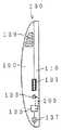
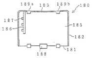
도1a 내지 도1d, 도2a 내지 도2b, 도3a 내지 도3c 및 도4a 내지 도4c는 본 발명의 모니터 장치(또는 정보 단말 장치)의 일실시 형태를 도시하고, 도1a는 장치의 정면도, 도1b는 장치의 상면도, 도1c는 장치의 좌측면도, 도1d는 장치의 우측면도, 도2a는 장치의 배면도, 도2b는 장치의 바닥면도, 도3a는 배터리를 배터리 수납 홈부에 삽입한 상태를 도시한 장치 배면부의 평면도, 도3b는 배터리의 우측면도, 도3c는 배터리를 배터리 수납 홈부에 장착한 상태를 도시한 장치 배면부의 평면도, 도4a는 배터리 커버를 스탠드 수납 홈부에 장착할(또는 스탠드 수납 홈부로부터 제거할) 때의 상태를 도시한 장치 배면부의 평면도, 도4b는 도4a의 B-B선 상의 단면도, 도4c는 배터리 커버를 이면측으로부터 본 평면도이다.1A-1D, 2A-2B, 3A-3C, and 4A-4C show an embodiment of the monitor device (or information terminal device) of the present invention, and FIG. 1A is a front view of the device. 1B is a top view of the device, FIG. 1C is a left side view of the device, FIG. 1D is a right side view of the device, FIG. 2A is a rear view of the device, FIG. 2B is a bottom view of the device, and FIG. 3B is a plan view of the right side of the battery, FIG. 3C is a plan view of the device back, showing the state in which the battery is mounted in the battery accommodating groove, and FIG. 4A is a battery cover mounted in the stand accommodating groove. Fig. 4B is a sectional view on the line BB of Fig. 4A, and Fig. 4C is a plan view of the battery cover as seen from the back side.
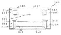
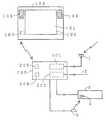
도5a 내지 도5c 및 도6은 본 발명의 베이스 장치의 일실시 형태를 도시하고, 도5a는 장치의 정면도, 도5b는 장치의 상면도, 도5c는 장치의 우측면도, 도6은 장치의 배면도이다. 좌측면은 우측면과 대칭이므로, 도시를 생략하였다.Figures 5a-5c and 6 show an embodiment of the base device of the present invention, Figure 5a is a front view of the device, Figure 5b is a top view of the device, Figure 5c is a right side view of the device, Figure 6 is a device Is the rear view of. Since the left side is symmetrical with the right side, illustration is omitted.
도7a 내지 도7b는 본 발명의 모니터 장치 및 베이스 장치의 일실시 형태로 이루어지는 시스템의 사용 형태를 도시하고, 도7a는 모니터 장치를 스탠드에 의해서 자립시킬 때의 상태를 도시한 측면도, 도7b는 모니터 장치를 베이스 장치에 세워 놓을 때의 상태를 도시한 측면도이다.7A to 7B show a usage form of the system comprising one embodiment of the monitor apparatus and the base apparatus of the present invention, and FIG. 7A is a side view showing a state when the monitor apparatus is self-supporting by a stand, and FIG. 7B is It is a side view which shows the state at the time of standing a monitor apparatus in a base apparatus.
도8은 모니터 장치와 베이스 장치로 이루어지는 시스템의 일예를 도시한 도면이다.8 is a diagram showing an example of a system composed of a monitor device and a base device.
이하, 도면을 인용하여 본 발명을 실시하기 위한 최량의 형태를 상세하게 서술한다.EMBODIMENT OF THE INVENTION Hereinafter, the best form for implementing this invention with reference to drawings is described in detail.
단, 본 발명의 모니터 장치와, 본 발명의 정보 단말 장치는 정면부에 디스플레이를 구비하고, 배터리로 구동되는 점에서 공통되므로, 이하에 있어서는 본 발명의 모니터 장치의 실시 형태와, 본 발명의 정보 단말 장치의 실시 형태를 공통된 실시 형태로서 나타낸다.However, since the monitor device of the present invention and the information terminal device of the present invention have a display in the front part and are common in that they are driven by a battery, the following describes the embodiment of the monitor device of the present invention and the information of the present invention. Embodiment of a terminal device is shown as common embodiment.
[모니터 장치(또는 정보 단말 장치)의 실시 형태][Embodiment of Monitor Device (or Information Terminal Device)]
도1a 내지 도1d에 도시한 바와 같이, 모니터 장치(100)는 정면부(110)와 배면부(150)를 접합하여 일체화한 구조가 되어, 그 정면부(110)에는 LCD(101)가 설치되고, 그 화면 상에는 터치 패널(102)이 설치되고, 화면 좌우 위치에는 상방부에 스피커(103, 104)가 설치되고, 하방부에 도5a 내지 도5c 및 도6에 도시하여 후술하는 베이스 장치(200) 사이의 무선 통신용의, 소위 패치 안테나(105, 106)가 설치된다.As shown in Figs. 1A to 1D, the
한편 패치 안테나(105)는 정면부(110)의 전방측에 반구면형의 방사 패턴을 형성하게 되고, 다른 쪽 패치 안테나(106)는 반대로 정면부(110)의 후방측에 반구면형의 방사 패턴을 형성하게 되어, 각 패치 안테나의 수신 레벨 정보에 의거하여 실제로 송신 및 수신을 행하는 패치 안테나가 선택됨으로써, 패치 안테나(105, 106) 전체적으로 전구면형의 방사 패턴을 갖는 안테나가 형성되어, 모니터 장치(100)와 베이스 장치(200)의 위치 관계의 여하에 관계없이, 모니터 장치(100)와 베이스 장치(200) 사이의 무선 통신이 양호하게 행해지도록 구성된다.On the other hand, the
정면부(110)의 우측 부분에는 스피커(104)의 하측에 인덱스 버튼(114), 점프 버튼(115) 및 채널 버튼(116, 117)이 설치되고, 정면부(110)의 좌측 부분에는 스피커(103)의 상측에 메일 자동 송수신 램프(LED)(118) 및 충전 램프(LED)(119)가 설치된다.An index button 114, a jump button 115, and
인덱스 버튼(114)은 이것을 압박함으로써, LCD(101) 상에 도시한 바와 같은 인덱스 화면이 표시되는 것으로, 사용자는 터치 펜으로 어느 하나의 메뉴에 터치함으로써, 텔레비전의 선국, 베이스 장치(200)에 접속된 외부 기기의 조작, 인터넷으로의 액세스, 메일의 작성ㆍ송신, 후술하는 앨범의 작성ㆍ표시 중 어느 하나를 행할 수 있다.The index button 114 presses this to display the index screen as shown on the
점프 버튼(115)은 이것을 누름으로써, 바로 앞에서 수신하고 있던 채널을 수신할 수 있는 것이며, 채널 버튼(116)은 이것을 누름으로써, LCD(101) 상에 표시되는 조작 화면이 텔레비전 → 외부 기기 → 인터넷 → 메일 → 앨범 → 텔레비전의 순으로 절환되는 것이며, 채널 버튼(117)은 이것을 누름으로써, LCD(101) 상에 표시되는 조작 화면이 상기한 순서와는 반대의 순으로 절환되는 것이다.By pressing this, the jump button 115 can receive the channel which was received immediately before, and the
앨범이라 함은, 디지털 카메라 등으로 촬영하여 메모리 스틱(출원인의 등록 상표)에 기록한 정지 화상이나, 메일로 수신한 정지 화상을 모니터 장치(100)에 도입하여 보존하고, LCD(101) 상에 일람 표시 또는 확대 표시하고, 또는 LCD(101) 상에서 작성한 메일에 첨부하는 것이다.The album refers to a still image recorded by a digital camera or the like recorded on a memory stick (registered trademark of an applicant) or a still image received by an e-mail in the
모니터 장치(100)의 상면(120)에는 터치 펜(109)이 수납되는 홈부(121), 전원 버튼(123), 전원 램프(LED)(124), 회선 절단 버튼(125), 회선 램프(LED)(126), 소음 버튼(127), 음량 증강 버튼(128) 및 음량 저감 버튼(129)이 설치된다.The
모니터 장치(100)의 좌측면(130)에는 LCD(101)의 밝기를 조정하는 손잡이(131), 헤드폰을 접속하는 단자(133), 키보드를 접속하는 단자를 덮는 개폐 가능한 커버(135), 모니터 장치(100)용의 AC 파워 어댑터를 접속하는 단자(137) 및 통기구(139)가 설치되고, 모니터 장치(100)의 우측면(140)에는 상기한 메모리 스틱 이 장착되는 슬롯(141), 메모리 스틱용 램프(LED)(145) 및 통기구(149)가 설치된다.On the
도2a에는 도1d에 도시한 슬롯(141)에 메모리 스틱(143)이 장착된 상태를 도시한다. 도2a 내지 도2b에 도시한 바와 같이, 정면부(110)와 배면부(150)는 나사(151)에 의해 접합된다.FIG. 2A illustrates a state in which the memory stick 143 is mounted in the slot 141 shown in FIG. 1D. As shown in Figs. 2A to 2B, the
배면부(150)의 상부에는 손잡이용 홈부(152)가 형성되고, 사용자는 이 손잡이용 홈부(152)에 손가락을 넣어 모니터 장치(100)를 협지함으로써, 모니터 장치(100)를 용이하게 운반할 수 있다.A handle groove 152 is formed on an upper portion of the
손잡이용 홈부(152)의 하측에는 스탠드 수납 홈부(153)가 형성되고, 이 스탠드 수납 홈부(153)에 스탠드(170)가 축(171)을 지지점으로 개폐(회전) 가능하도록 부착된다.A stand accommodating
또, 배면부(150)에는 스탠드 수납 홈부(153)에 둘러싸이는 위치에, 후술하는 바와 같은 배터리 수납 홈부가 형성되어, 그 배터리 수납 홈부에 배터리(190)가 장착되고, 스탠드 수납 홈부(153)에 배터리 커버(180)가 장착된다.In addition, the
정면부(110) 및 배면부(150)의 바닥부, 즉 모니터 장치(100)의 바닥면(160)에는 도7b에 도시하여 후술하는 바와 같이 모니터 장치(100)를 베이스 장치(200)에 세워 놓을 때에 베이스 장치(200)의 보유 지지용 레일(212)이 삽입되는 홈부(161)가 형성된다. 홈부(161)의 좌우의 면(162d, 162e)은 홈부(101)의 바닥면에 가까워질수록 양자의 간격이 좁아지도록 경사진 면이 되고, 이 홈부(161)의 바닥면으로부터 후방측 면에 걸쳐, 한 쌍의 충전 단자(165)가 설치된다.In the bottom portion of the
또, 모니터 장치(100)의 바닥면(160)에는 홈부(161)의 좌우 위치에, 도7a에 도시하여 후술하는 바와 같이 스탠드(170)를 개방하여 모니터 장치(100)를 자립시킬 때에 모니터 장치(100)가 미끄러지는 것을 방지하는, 고무 등으로 이루어지는 미끄럼 방지 부재(169)가 부착된다.In addition, the
도3a 내지 도3c는 배면부(150)의 스탠드(170)를 개방하고, 도2a 내지 도2b에 도시한 배터리 커버(180)를 스탠드 수납 홈부(153)로부터 떼어 낸 상태를 도시한다. 도3a 내지 도3c에 도시한 바와 같이, 배면부(150)의 스탠드 수납 홈부(153)의 내측에는 칸막이 벽(154)에 의해 스탠드 수납 홈부(153)와 이격되어 배터리 수납 홈부(155)가 형성되고, 이 배터리 수납 홈부(155)의 우측 부분에는 접속 단자(156a, 156b)가 설치되고, 레일(157)이 형성되는 동시에, 배터리 수납 홈부(155)의 상방의 벽면에는 걸림용 홈부(158)가 형성되고, 칸막이 벽(154)의 하부에는 구멍(159a, 159b)이 형성된다.3A to 3C show a state in which the
배터리(190)의 표면에는 배터리(190)의 장착 방향을 나타내는 마크(191)가 형성되고, 우측면에는 각각 내부에 접속 단자가 설치된 구멍(196a, 196b)이 형성되고, 우측면을 향해 배면에는 안내 홈(197)이 형성된다.A
도4a 내지 도4c에 도시한 바와 같이, 배터리 커버(180)는 상단부 모서리(181)를 제외하고 측부 및 하부가 측벽(182) 및 하부벽(183)으로서 형성되고, 표면에는 배터리 커버(180)를 스탠드 수납 홈부(153)로부터 떼어 낼 때의 방향을 나타내고, 또한 미끄럼 방지 처리가 실시된 조작부(184)가 형성되고, 상단부 모서리(181)에는 걸림 부재(188)가 형성되고, 하부벽(183)에는 걸림 부재(189a, 189b)가 형성된다.As shown in FIGS. 4A-4C, the
또, 배터리 커버(180)의 이면(185)에는 측벽(182)과 평행하게, 배터리(190)의 좌측면을 압박하는 리브(186)가 형성되는 동시에, 이 압박용 리브(186)를 보강하는 리브(187)가 형성된다.In addition,
배터리(190)는, 도3a에 도시한 바와 같이 스탠드(170)를 개방하고, 스탠드 수납 홈부(153)로부터 배터리 커버(180)를 떼어 낸 상태에서, 배터리 수납 홈부(155) 내의 좌측 위치에 삽입한 후, 도3c에 도시한 바와 같이, 마크(191)가 나타내는 우측 방향으로 슬라이드시킨다.The
이에 의해, 배터리 수납 홈부(155)의 레일(157)이 배터리(190)의 안내 홈(197)에 삽입되고, 배터리 수납 홈부(155)를 향한 접속 단자(156a, 156b)가 배터리(190)의 구멍(196a, 196b)에 삽입되고, 구멍(196a, 196b) 내부의 접속 단자에 접속되어, 배터리(190)가 배터리 수납 홈부(155)에 장착되어 모니터 장치(100)를 배터리(190)에 의해 구동할 수 있는 상태가 된다.As a result, the rail 157 of the
이와 같이 배터리(190)를 배터리 수납 홈부(155)에 장착하였다면, 도4a에 도시한 바와 같이, 배터리 커버(180)를 스탠드 수납 홈부(153)에 삽입하여 상방으로 슬라이드시킨다. 이에 의해, 걸림 부재(188)가 홈부(158)에 걸리고, 걸림 부재(189a, 189b)가 구멍(159a, 159b)에 걸리어 도2a 내지 도2b에 도시한 바와 같이 배터리 커버(180)가 스탠드 수납 홈부(153)에 장착된다.When the
이와 같이 배터리 커버(130)가 스탠드 수납 홈부(153)에 장착된 상태에서는, 배터리 커버(180) 이면(185)의 압박용 리브(186)가 배터리(190) 좌측면을 압박함으 로써, 접속 단자(156a, 156b)로의 배터리(190)의 접속이 보유 지지되고, 걸림 부재(188)가 수납 홈부(158)에 걸리고 있음으로써, 배터리 커버(180)가 하방으로 탈락되는 일이 방지되는 동시에, 걸림 부재(189a, 189b)가 구멍(159a, 159b)에 걸리고 있음으로써, 배터리 커버(180)가 후방측으로 벗겨지는 것이 방지된다.As described above, in the state where the
또, 모니터 장치(100)를 운반할 때에는, 도2a 내지 도2b에 도시한 바와 같이 스탠드(170)를 스탠드 수납 홈부(153)에 수납함으로써, 배터리 커버(180)의 스탠드 수납 홈부(153)로부터의 누락, 따라서 배터리(190)의 배터리 수납 홈부(155)로부터의 누락이, 보다 확실하게 방지된다.In addition, when carrying the
배터리(190)를 배터리 수납 홈부(155)로부터 취출할 때에는, 도4a에 도시한 바와 같이, 스탠드(170)를 개방한 상태에서, 조작부(184)를 압박하면서 배터리 커버(180)를 하방으로 슬라이드시켜 걸림 부재(188)를 홈부(158)로부터 제거하고, 걸림 부재(189a, 189b)를 구멍(159a, 159b)으로부터 제거한 후, 배터리 커버(180)를 전방측으로 인출하고, 도3c에 도시한 바와 같이 배터리 수납 홈부(155)에 장착되어 있는 배터리(190)를 도3a에 도시한 바와 같이 좌측으로 슬라이드시킨 후, 전방측으로 인출한다.When taking out the
[베이스 장치의 실시 형태][Embodiment of Base Unit]
도5a 내지 도5c에 도시한 바와 같이, 베이스 장치(200)는 정면부(210)와 후방부(230)에 부착된 배면부(250)를 접합하여 일체화한 구조가 되고, 그 정면부(210)에는 상방부의 좌우 위치에, 모니터 장치(100)와의 사이의 무선 통신용의, 소위 패치 안테나(205, 206)가 설치된다.As shown in FIGS. 5A to 5C, the
모니터 장치(100)의 패치 안테나(105, 106)와 마찬가지로, 한 쪽 패치 안테나(205)는 정면부(210)의 전방측에 반구면형의 방사 패턴을 형성하는 것이 되고, 다른 쪽 패치 안테나(206)는 반대로 정면부(210)의 후방측에 반구면형의 방사 패턴을 형성하는 것이 되어, 각 패치 안테나의 수신 레벨 정보에 의거하여 실제로 송신 및 수신을 행하는 패치 안테나가 선택됨으로써, 패치 안테나(205, 206) 전체적으로, 전구면형의 방사 패턴을 갖는 안테나가 형성되고, 모니터 장치(100)와 베이스 장치(200)의 위치 관계의 여하에 관계없이, 모니터 장치(100)와 베이스 장치(200) 사이의 무선 통신이 양호하게 행해지도록 구성된다.Similar to the
정면부(210) 및 배면부(250)는, 어느 정도 후방측으로 기울어진 것이 되고, 정면부(210)의 하부에는 모니터 장치(100)의 배면부(150)의 곡면 슬로프 형상에 따른 곡면 슬로프 형상의 다이부(211)가 형성되고, 이 다이부(211)의 하부에는 모니터 장치(100)를 베이스 장치(200)에 세워 놓을 때에 모니터 장치(100)의 바닥면(160) 홈부(161)에 삽입되는 보유 지지용 레일(212)이 형성된다.The
보유 지지용 레일(212)은 전방측 면(212b)이, 어느 정도 후방측으로 기울어진 면이 되고, 후방측 면(212c)이 곡면형으로 전방측으로 기울어진 면이 되어, 좌우의 면(212d, 212e)이 정상면(212a)에 가까워질수록 양자의 간격이 좁아지도록 경사진 면이 되고, 이 보유 지지용 레일(212)의 정상면(212a)으로부터 후방측 면(212c)에 걸쳐, 한 쌍의 충전 단자(215)가 설치된다.The holding
또한, 정면부(210)에는 다이부(211)에 걸치는 좌우 위치 및 상부의 좌우 위치에, 모니터 장치(100)를 베이스 장치(200)에 세워 놓을 때의 충격을 완화하는, 고무 등으로 이루어지는 완충 부재(217, 218)가 부착되는 동시에, 중앙부에 전원 투입시에 점등하고, 회선 접속시에 점멸하는 램프(LED)(219)가 설치된다.In addition, the
배면부(250)의 상면(220)에는 전원 스위치(223)가 설치되고, 후방부(230)의 양측면에는 통기구(240)가 설치되고, 후방부(230)의 바닥면에는 고무 등으로 이루어지는 미끄럼 방지 부재(261)가 부착된다. 정면부(210)와 배면부(250)는 도6에 도시한 바와 같이 나사(251)에 의해 접합된다.A
도5a 내지 도5c 및 도6에서는 생략하였지만, 후방부(230) 내에는 도8에 도시한 바와 같은 튜너 및 모뎀이 설치된다. 또, 도5a 내지 도5c 및 도6에서는 생략하였지만, 베이스 장치(200) 내에는 충전 단자(215)에 접속된 충전 회로가 설치된다.Although omitted in FIGS. 5A to 5C and 6, the rear portion 230 includes a tuner and a modem as shown in FIG. 8. Although not shown in FIGS. 5A to 5C and 6, a charging circuit connected to the charging
도6에 도시한 바와 같이, 후방부(230)의 배면에는 홈부(231)가 형성되고, 이 홈부(231)에는 전화 회선에 접속하는 단자(233), VHF/UHF 안테나에 접속하는 단자(234), 외부 기기로부터 비디오 신호(영상 신호 및 음성 신호)를 입력하는 단자(235), AV 마우스를 접속하는 단자(236), 어스 단자(237), 베이스 장치(200)용의 AC 파워 어댑터를 접속하는 단자(238) 등이 설치된다.As shown in FIG. 6, a groove portion 231 is formed on the rear surface of the rear portion 230, and the groove portion 231 has a terminal 233 connected to a telephone line and a terminal 234 connected to a VHF / UHF antenna. ), A terminal 235 for inputting a video signal (video signal and audio signal) from an external device, a terminal 236 for connecting an AV mouse, an
[시스템의 사용 형태][Type of use of the system]
상술한 모니터 장치(100) 및 베이스 장치(200)에서는, 사용자는 베이스 장치(200)를 거실 등의 장소에 고정적으로 배치하고, 모니터 장치(100)를 주거 내부나 정원 등의 임의의 장소로 운반하여, 임의의 장소에서 손에 있는 모니터 장치(100)에 의해, 텔레비전 방송을 수신하고, 인터넷에 액세스하여 전자 메일을 송수신하는 등의 기능을 실행할 수 있다,In the above-described
이 경우, 사용자는 모니터 장치(100)를 손에 들고 사용할 수도 있지만, 도7a에 도시한 바와 같이, 스탠드(170)를 스탠드 수납 홈부(153)로부터 인출하여, 모니터 장치(100)의 바닥면과 스탠드(170)에 의해, 모니터 장치(100)를 적당한 면(11) 상에 적당한 경사각으로 자립시킬 수 있고, 화살표 15의 방향으로부터 화면(101)을 볼 수 있다.In this case, the user may use the
모니터 장치(100)에 장착된 배터리(190)를 충전할 때에는, 도7b에 도시한 바와 같이, 스탠드(170)를 스탠드 수납 홈부(153)에 수납하여, 면(12) 상에 설치된 베이스 장치(200)의 보유 지지용 레일(212)을 모니터 장치(100)의 홈부(161)에 삽입하도록, 모니터 장치(100)를 베이스 장치(200)의 정면부(210)에 세워 놓는다.When charging the
이 경우, 도2a 내지 도2b에 도시한 바와 같이 홈부(161)의 좌우의 면(162d, 162e)이 경사면이 되고, 도5a 내지 도5c에 도시한 바와 같이 보유 지지용 레일(212)의 좌우의 면(212d, 212e)도 경사면이 되어 있으므로, 베이스 장치(200)의 보유 지지용 레일(212)을 모니터 장치(100)의 홈부(161)에 용이하게 삽입할 수 있다.In this case, as shown in Figs. 2A to 2B, the left and right surfaces 162d and 162e of the
그리고, 이와 같이 베이스 장치(200)의 보유 지지용 레일(212)이 모니터 장치(100)의 홈부(161)에 삽입된 상태에서는, 베이스 장치(200)측의 충전 단자(215)와 모니터 장치(100)측의 충전 단자(165)가 충분한 접촉압으로 접촉하므로[단, 도7b에서는 충전 단자(215)와 충전 단자(165)를 구별하기 위해, 편의상 양자간에 간극이 존재하는 것처럼 도시함], 베이스 장치(200)의 충전 회로에 의해, 모니터 장치(100)에 장착된 배터리(190)를 충전할 수 있다.And in this state in which the holding
게다가, 이 때 모니터 장치(100)의 전방면측이 베이스 장치(200)에 의해 씌워지는 일이 전혀 없으므로, 충전시에 있어서도, 도7a에 도시한 바와 같은 비충전시와 완전히 마찬가지로, 사용자는 화면(101)을 보는 등, 모니터 장치(100)를 사용할 수 있다.In addition, since the front surface side of the
배터리(190)를 충전하지 않을 때에도, 이와 같이 모니터 장치(100)를 베이스 장치(200)에 세워 놓고 사용할 수 있다.Even when the
[다른 실시 형태][Other Embodiments]
베이스 장치와 함께 이용되는 모니터 장치로서는, 정면부에 디스플레이를 구비하고, 배터리로 구동되는 장치이면 배터리가 장치 배면부가 아닌, 그 밖의 부분에 장착되는 장치라도 좋다.As the monitor device used together with the base device, a device having a display in the front part and a device driven by a battery may be a device that is mounted on another part instead of the device back part.
또, 상술한 실시 형태는 본 발명의 정보 단말 장치가 모니터 장치와 베이스 장치로 이루어지는 시스템의 모니터 장치를 구성하는 경우이지만, 본 발명의 정보 단말 장치는 정면부에 디스플레이를 구비하여 배터리로 구동되고, 또한 배터리가 장치 배면부에 장착되는 장치이면, 상기한 바와 같은 모니터 장치와 베이스 장치로 이루어지는 시스템의 모니터 장치에 한정되지 않고, 그 밖의 정보 단말 장치라도 좋다.
Moreover, although the above-mentioned embodiment is a case where the information terminal apparatus of this invention comprises the monitor apparatus of the system which consists of a monitor apparatus and a base apparatus, the information terminal apparatus of this invention is provided with a display in a front part, and is driven by a battery, In addition, as long as a battery is a device mounted in the apparatus back part, it is not limited to the monitor apparatus of the system which consists of a monitor apparatus and a base apparatus as mentioned above, and other information terminal apparatus may be sufficient.
Claims (12)
Translated fromKoreanApplications Claiming Priority (4)
| Application Number | Priority Date | Filing Date | Title |
|---|---|---|---|
| JPJP-P-2000-00366127 | 2000-11-30 | ||
| JP2000366127AJP4328932B2 (en) | 2000-11-30 | 2000-11-30 | Monitor device and base device |
| JPJP-P-2000-00366128 | 2000-11-30 | ||
| JP2000366128AJP2002169630A (en) | 2000-11-30 | 2000-11-30 | Information terminal device |
Publications (2)
| Publication Number | Publication Date |
|---|---|
| KR20020076271A KR20020076271A (en) | 2002-10-09 |
| KR100846245B1true KR100846245B1 (en) | 2008-07-16 |
Family
ID=26605019
Family Applications (1)
| Application Number | Title | Priority Date | Filing Date |
|---|---|---|---|
| KR1020027009740AExpired - Fee RelatedKR100846245B1 (en) | 2000-11-30 | 2001-11-29 | Monitor device, base device and information terminal device |
Country Status (7)
| Country | Link |
|---|---|
| US (1) | US6778935B2 (en) |
| EP (1) | EP1339232B1 (en) |
| KR (1) | KR100846245B1 (en) |
| CN (2) | CN1269355C (en) |
| CA (1) | CA2396861C (en) |
| DE (1) | DE60135371D1 (en) |
| WO (1) | WO2002045418A1 (en) |
Families Citing this family (24)
| Publication number | Priority date | Publication date | Assignee | Title |
|---|---|---|---|---|
| US7010331B2 (en)* | 2002-05-20 | 2006-03-07 | Kyocera Wireless Corp. | Wireless communication device with latch |
| US6751552B1 (en) | 2002-06-28 | 2004-06-15 | Garmin Ltd. | Rugged, waterproof, navigation device with touch panel |
| US7019871B2 (en)* | 2003-04-08 | 2006-03-28 | Tr Marketing, Inc. | Digital photo album having a built-in scanner |
| US7079293B2 (en)* | 2003-04-08 | 2006-07-18 | Tr Marketing, Inc. | Digital album and methods of use |
| JP3694014B2 (en)* | 2003-04-17 | 2005-09-14 | シャープ株式会社 | Wireless communication device |
| JP3873942B2 (en)* | 2003-07-11 | 2007-01-31 | ソニー株式会社 | Display stand and receiver |
| EP1730471B1 (en)* | 2004-03-15 | 2015-07-01 | TomTom International B.V. | Navigation device displaying dynamic travel information |
| DE102005011454B4 (en)* | 2004-03-18 | 2007-01-04 | Loewe Opta Gmbh | TV receiver with integrated antenna |
| USD528444S1 (en)* | 2004-06-14 | 2006-09-19 | Omron Corporation | Sensor controller |
| KR100700785B1 (en)* | 2005-04-29 | 2007-03-27 | 엘지전자 주식회사 | Battery pack mounting structure of portable display |
| US7541774B2 (en)* | 2005-04-30 | 2009-06-02 | Motorola, Inc. | Battery charger having oblique coupling rails |
| US8704487B2 (en)* | 2007-04-11 | 2014-04-22 | Hewlett-Packard Development Company, L.P. | Electronic device having a battery pack to support a display |
| CN102184677A (en)* | 2011-03-04 | 2011-09-14 | 明基电通有限公司 | Display device |
| JP5175968B1 (en) | 2011-10-28 | 2013-04-03 | 株式会社東芝 | Stand and electronics |
| US9122451B2 (en)* | 2013-09-30 | 2015-09-01 | Sonos, Inc. | Capacitive proximity sensor configuration including a speaker grille |
| US9223353B2 (en) | 2013-09-30 | 2015-12-29 | Sonos, Inc. | Ambient light proximity sensing configuration |
| US10206022B2 (en)* | 2015-06-16 | 2019-02-12 | Crestron Electronics, Inc. | Touch screen control device with speakers |
| CN115135222A (en)* | 2020-02-21 | 2022-09-30 | 安布股份有限公司 | Video processing apparatus |
| US11109741B1 (en) | 2020-02-21 | 2021-09-07 | Ambu A/S | Video processing apparatus |
| US11166622B2 (en) | 2020-02-21 | 2021-11-09 | Ambu A/S | Video processing apparatus |
| US10835106B1 (en)* | 2020-02-21 | 2020-11-17 | Ambu A/S | Portable monitor |
| US10980397B1 (en)* | 2020-02-21 | 2021-04-20 | Ambu A/S | Video processing device |
| CN112995553A (en)* | 2021-03-16 | 2021-06-18 | 广东长虹电子有限公司 | Novel liquid crystal display television with additional lithium battery |
| JP7319323B2 (en)* | 2021-05-28 | 2023-08-01 | 任天堂株式会社 | Electronics and equipment holding systems |
Citations (7)
| Publication number | Priority date | Publication date | Assignee | Title |
|---|---|---|---|---|
| US5375076A (en)* | 1993-09-10 | 1994-12-20 | Compaq Computer Corporation | Combined notepad and notebook computer |
| JPH10257194A (en)* | 1997-03-12 | 1998-09-25 | Sony Corp | Information processing apparatus and method, and display control apparatus and method |
| US5824431A (en)* | 1996-03-19 | 1998-10-20 | Fujitsu Limited | Portable apparatus and battery locking mechanism |
| US5898405A (en) | 1994-12-27 | 1999-04-27 | Kabushiki Kaisha Toshiba | Omnidirectional antenna formed one or two antenna elements symmetrically to a ground conductor |
| EP0967797A2 (en)* | 1998-06-26 | 1999-12-29 | Sharp Kabushiki Kaisha | An image display and remote control system capable of displaying two distinct images |
| US6016248A (en) | 1996-08-19 | 2000-01-18 | International Business Machines Corporation | Hand held tablet computer having external mechanisms for facilitating positioning and operation |
| KR20000044288A (en)* | 1998-12-30 | 2000-07-15 | 윤종용 | Hands-free call device for automobile |
Family Cites Families (12)
| Publication number | Priority date | Publication date | Assignee | Title |
|---|---|---|---|---|
| JPS53166819U (en)* | 1977-06-03 | 1978-12-27 | ||
| JPS6127285A (en) | 1984-07-18 | 1986-02-06 | Mitsubishi Paper Mills Ltd | Thermal recording material |
| JPS6127285U (en)* | 1984-07-20 | 1986-02-18 | ソニー株式会社 | Electronics |
| JPH087529B2 (en)* | 1988-04-25 | 1996-01-29 | 富士通株式会社 | Display device |
| JP3493746B2 (en)* | 1994-09-27 | 2004-02-03 | ソニー株式会社 | Electronics |
| JP3641299B2 (en)* | 1995-07-10 | 2005-04-20 | ペンタックス株式会社 | Image input device |
| US6369952B1 (en)* | 1995-07-14 | 2002-04-09 | I-O Display Systems Llc | Head-mounted personal visual display apparatus with image generator and holder |
| JPH09121317A (en)* | 1995-10-25 | 1997-05-06 | Casio Comput Co Ltd | Small tv receiver |
| KR100303081B1 (en)* | 1997-10-13 | 2001-11-22 | 윤종용 | Portable computer for mounting communication devices |
| US6097441A (en)* | 1997-12-31 | 2000-08-01 | Eremote, Inc. | System for dual-display interaction with integrated television and internet content |
| JP3453506B2 (en)* | 1998-01-27 | 2003-10-06 | 富士写真フイルム株式会社 | Image reading device |
| JP3280321B2 (en)* | 1998-09-14 | 2002-05-13 | 富士通株式会社 | Function expansion device and electronic equipment system |
- 2001
- 2001-11-29EPEP01999112Apatent/EP1339232B1/ennot_activeExpired - Lifetime
- 2001-11-29DEDE60135371Tpatent/DE60135371D1/ennot_activeExpired - Lifetime
- 2001-11-29WOPCT/JP2001/010427patent/WO2002045418A1/enactiveIP Right Grant
- 2001-11-29KRKR1020027009740Apatent/KR100846245B1/ennot_activeExpired - Fee Related
- 2001-11-29CNCNB2004100078799Apatent/CN1269355C/ennot_activeExpired - Fee Related
- 2001-11-29USUS10/182,476patent/US6778935B2/ennot_activeExpired - Fee Related
- 2001-11-29CACA002396861Apatent/CA2396861C/ennot_activeExpired - Fee Related
- 2001-11-29CNCNB018042619Apatent/CN1178486C/ennot_activeExpired - Fee Related
Patent Citations (7)
| Publication number | Priority date | Publication date | Assignee | Title |
|---|---|---|---|---|
| US5375076A (en)* | 1993-09-10 | 1994-12-20 | Compaq Computer Corporation | Combined notepad and notebook computer |
| US5898405A (en) | 1994-12-27 | 1999-04-27 | Kabushiki Kaisha Toshiba | Omnidirectional antenna formed one or two antenna elements symmetrically to a ground conductor |
| US5824431A (en)* | 1996-03-19 | 1998-10-20 | Fujitsu Limited | Portable apparatus and battery locking mechanism |
| US6016248A (en) | 1996-08-19 | 2000-01-18 | International Business Machines Corporation | Hand held tablet computer having external mechanisms for facilitating positioning and operation |
| JPH10257194A (en)* | 1997-03-12 | 1998-09-25 | Sony Corp | Information processing apparatus and method, and display control apparatus and method |
| EP0967797A2 (en)* | 1998-06-26 | 1999-12-29 | Sharp Kabushiki Kaisha | An image display and remote control system capable of displaying two distinct images |
| KR20000044288A (en)* | 1998-12-30 | 2000-07-15 | 윤종용 | Hands-free call device for automobile |
Also Published As
| Publication number | Publication date |
|---|---|
| CA2396861C (en) | 2009-08-04 |
| US6778935B2 (en) | 2004-08-17 |
| DE60135371D1 (en) | 2008-09-25 |
| EP1339232A1 (en) | 2003-08-27 |
| CN1178486C (en) | 2004-12-01 |
| CN1538744A (en) | 2004-10-20 |
| CN1397133A (en) | 2003-02-12 |
| EP1339232B1 (en) | 2008-08-13 |
| WO2002045418A1 (en) | 2002-06-06 |
| KR20020076271A (en) | 2002-10-09 |
| CA2396861A1 (en) | 2002-06-06 |
| US20030004690A1 (en) | 2003-01-02 |
| EP1339232A4 (en) | 2006-07-19 |
| CN1269355C (en) | 2006-08-09 |
Similar Documents
| Publication | Publication Date | Title |
|---|---|---|
| KR100846245B1 (en) | Monitor device, base device and information terminal device | |
| US6968206B1 (en) | Portable television/cellular phone device | |
| JP4406466B2 (en) | Media player system | |
| US5214514A (en) | Compact video/sound apparatus with foldable screen | |
| JP4328932B2 (en) | Monitor device and base device | |
| US8565843B1 (en) | Portable device shell | |
| EP1968285A2 (en) | Mobile terminal | |
| US20050052837A1 (en) | Portable information terminal | |
| US7054670B2 (en) | Cellular phone structure and portable electronic apparatus | |
| CN103427224B (en) | Mobile terminal | |
| US7636236B1 (en) | Multi-functional laptop | |
| KR101185190B1 (en) | Mobile phone case | |
| US20080244144A1 (en) | Hand-held remote control for electronic entertainment appliance | |
| US7899398B2 (en) | Portable karaoke system | |
| JP2002169630A (en) | Information terminal device | |
| US8145266B2 (en) | Portable audio/video playback apparatus | |
| JP2006121455A (en) | Headphone, headset, and recording/reproducing system using the headphone or headset | |
| CN210724888U (en) | Wireless talkback functional mobile phone | |
| JP2005136580A (en) | Television equipment | |
| JPH10164392A (en) | Remote control transmitter, TV tuner, personal computer system | |
| EP1600970A1 (en) | Data reception storage device | |
| HK1126582B (en) | Docking station | |
| HK1126576B (en) | Plug connector | |
| HK1126903B (en) | Electronic apparatus | |
| HK1126580B (en) | Adapter for hand-held media player |
Legal Events
| Date | Code | Title | Description |
|---|---|---|---|
| PA0105 | International application | St.27 status event code:A-0-1-A10-A15-nap-PA0105 | |
| PG1501 | Laying open of application | St.27 status event code:A-1-1-Q10-Q12-nap-PG1501 | |
| A201 | Request for examination | ||
| PA0201 | Request for examination | St.27 status event code:A-1-2-D10-D11-exm-PA0201 | |
| R18-X000 | Changes to party contact information recorded | St.27 status event code:A-3-3-R10-R18-oth-X000 | |
| E902 | Notification of reason for refusal | ||
| PE0902 | Notice of grounds for rejection | St.27 status event code:A-1-2-D10-D21-exm-PE0902 | |
| T11-X000 | Administrative time limit extension requested | St.27 status event code:U-3-3-T10-T11-oth-X000 | |
| E13-X000 | Pre-grant limitation requested | St.27 status event code:A-2-3-E10-E13-lim-X000 | |
| P11-X000 | Amendment of application requested | St.27 status event code:A-2-2-P10-P11-nap-X000 | |
| P13-X000 | Application amended | St.27 status event code:A-2-2-P10-P13-nap-X000 | |
| E701 | Decision to grant or registration of patent right | ||
| PE0701 | Decision of registration | St.27 status event code:A-1-2-D10-D22-exm-PE0701 | |
| GRNT | Written decision to grant | ||
| PR0701 | Registration of establishment | St.27 status event code:A-2-4-F10-F11-exm-PR0701 | |
| PR1002 | Payment of registration fee | St.27 status event code:A-2-2-U10-U12-oth-PR1002 Fee payment year number:1 | |
| PG1601 | Publication of registration | St.27 status event code:A-4-4-Q10-Q13-nap-PG1601 | |
| PN2301 | Change of applicant | St.27 status event code:A-5-5-R10-R13-asn-PN2301 St.27 status event code:A-5-5-R10-R11-asn-PN2301 | |
| FPAY | Annual fee payment | Payment date:20110706 Year of fee payment:4 | |
| PR1001 | Payment of annual fee | St.27 status event code:A-4-4-U10-U11-oth-PR1001 Fee payment year number:4 | |
| LAPS | Lapse due to unpaid annual fee | ||
| PC1903 | Unpaid annual fee | St.27 status event code:A-4-4-U10-U13-oth-PC1903 Not in force date:20120709 Payment event data comment text:Termination Category : DEFAULT_OF_REGISTRATION_FEE | |
| PC1903 | Unpaid annual fee | St.27 status event code:N-4-6-H10-H13-oth-PC1903 Ip right cessation event data comment text:Termination Category : DEFAULT_OF_REGISTRATION_FEE Not in force date:20120709 | |
| PN2301 | Change of applicant | St.27 status event code:A-5-5-R10-R13-asn-PN2301 St.27 status event code:A-5-5-R10-R11-asn-PN2301 |