KR100845079B1 - High temperature and high pressure steam sterilization method for endoscope, and endoscope - Google Patents
High temperature and high pressure steam sterilization method for endoscope, and endoscopeDownload PDFInfo
- Publication number
- KR100845079B1 KR100845079B1KR1020067001315AKR20067001315AKR100845079B1KR 100845079 B1KR100845079 B1KR 100845079B1KR 1020067001315 AKR1020067001315 AKR 1020067001315AKR 20067001315 AKR20067001315 AKR 20067001315AKR 100845079 B1KR100845079 B1KR 100845079B1
- Authority
- KR
- South Korea
- Prior art keywords
- endoscope
- sterilization
- space
- outside
- steam
- Prior art date
- Legal status (The legal status is an assumption and is not a legal conclusion. Google has not performed a legal analysis and makes no representation as to the accuracy of the status listed.)
- Expired - Fee Related
Links
Images


Classifications
- A—HUMAN NECESSITIES
- A61—MEDICAL OR VETERINARY SCIENCE; HYGIENE
- A61B—DIAGNOSIS; SURGERY; IDENTIFICATION
- A61B1/00—Instruments for performing medical examinations of the interior of cavities or tubes of the body by visual or photographical inspection, e.g. endoscopes; Illuminating arrangements therefor
- A61B1/12—Instruments for performing medical examinations of the interior of cavities or tubes of the body by visual or photographical inspection, e.g. endoscopes; Illuminating arrangements therefor with cooling or rinsing arrangements
- A61B1/121—Instruments for performing medical examinations of the interior of cavities or tubes of the body by visual or photographical inspection, e.g. endoscopes; Illuminating arrangements therefor with cooling or rinsing arrangements provided with means for cleaning post-use
- A61B1/125—Instruments for performing medical examinations of the interior of cavities or tubes of the body by visual or photographical inspection, e.g. endoscopes; Illuminating arrangements therefor with cooling or rinsing arrangements provided with means for cleaning post-use using fluid circuits
- A—HUMAN NECESSITIES
- A61—MEDICAL OR VETERINARY SCIENCE; HYGIENE
- A61B—DIAGNOSIS; SURGERY; IDENTIFICATION
- A61B1/00—Instruments for performing medical examinations of the interior of cavities or tubes of the body by visual or photographical inspection, e.g. endoscopes; Illuminating arrangements therefor
- A61B1/12—Instruments for performing medical examinations of the interior of cavities or tubes of the body by visual or photographical inspection, e.g. endoscopes; Illuminating arrangements therefor with cooling or rinsing arrangements
- A—HUMAN NECESSITIES
- A61—MEDICAL OR VETERINARY SCIENCE; HYGIENE
- A61L—METHODS OR APPARATUS FOR STERILISING MATERIALS OR OBJECTS IN GENERAL; DISINFECTION, STERILISATION OR DEODORISATION OF AIR; CHEMICAL ASPECTS OF BANDAGES, DRESSINGS, ABSORBENT PADS OR SURGICAL ARTICLES; MATERIALS FOR BANDAGES, DRESSINGS, ABSORBENT PADS OR SURGICAL ARTICLES
- A61L2/00—Methods or apparatus for disinfecting or sterilising materials or objects other than foodstuffs or contact lenses; Accessories therefor
- A61L2/02—Methods or apparatus for disinfecting or sterilising materials or objects other than foodstuffs or contact lenses; Accessories therefor using physical phenomena
- A61L2/04—Heat
- A61L2/06—Hot gas
- A61L2/07—Steam
Landscapes
- Health & Medical Sciences (AREA)
- Life Sciences & Earth Sciences (AREA)
- Surgery (AREA)
- Veterinary Medicine (AREA)
- Public Health (AREA)
- General Health & Medical Sciences (AREA)
- Animal Behavior & Ethology (AREA)
- Optics & Photonics (AREA)
- Pathology (AREA)
- Engineering & Computer Science (AREA)
- Biomedical Technology (AREA)
- Heart & Thoracic Surgery (AREA)
- Medical Informatics (AREA)
- Molecular Biology (AREA)
- Radiology & Medical Imaging (AREA)
- Physics & Mathematics (AREA)
- Nuclear Medicine, Radiotherapy & Molecular Imaging (AREA)
- Biophysics (AREA)
- Epidemiology (AREA)
- Apparatus For Disinfection Or Sterilisation (AREA)
- Endoscopes (AREA)
Abstract
Translated fromKoreanDescription
Translated fromKorean본 발명은 내시경을 고온 고압 증기로 멸균 처리하는 내시경의 고온 고압 증기 멸균 처리 방법 및 내시경에 관한 것이다.The present invention relates to a high temperature and high pressure steam sterilization method and endoscope of the endoscope for sterilizing the endoscope with high temperature and high pressure steam.
최근, 체강 내 등에 삽입함으로써 체강 내의 심부 등을 관찰하거나, 필요에 따라서 처치구를 이용함으로써 치료, 처치 등을 할 수 있는 내시경이 의료 분야에 있어서 널리 이용되고 있다.Background Art In recent years, endoscopes capable of observing deep insides of the body cavity by inserting them into the body cavity or the like, or performing treatment, treatment, and the like by using a treatment instrument, have been widely used in the medical field.
의료용 내시경의 경우, 사용한 내시경을 확실하게 소독 멸균하는 것이 감염증 등을 방지하기 위해 필요 불가결해진다.In the case of medical endoscopes, sterilization and sterilization of used endoscopes without fail is essential to prevent infectious diseases and the like.
최근에는, 소독 멸균을 하는 경우, 번잡한 작업을 수반하지 않고, 멸균 후에 바로 사용할 수 있고, 게다가 운전 비용의 면에서도 유리해지는 오토클레이브(autoclave) 멸균(고온 고압 증기 멸균)이 내시경 기기의 멸균 방법으로서 주류를 이루고 있다.Recently, in the case of sterilization sterilization, autoclave sterilization (high temperature, high pressure steam sterilization) which can be used immediately after sterilization without any complicated work, and also advantageous in terms of operating cost, is a method of sterilizing an endoscope device. As mainstream.
예컨대, 일본 특허 공개 제2000-51323호 공보의 종래예에서는, 내시경을 고온 고압 증기 멸균할 때에, 내시경 내외의 압력차에 의한 내시경의 외피 파손을 방지하기 위한 멸균 처리 방법이 개시되어 있다.For example, in the prior art of Unexamined-Japanese-Patent No. 2000-51323, when sterilizing an endoscope at high temperature, high pressure steam, the sterilization method for preventing the breakage of the endoscope by the pressure difference inside and outside an endoscope is disclosed.
그러나 상기 종래예에서는 내시경에 내장되어, 단부가 내시경 외부에 개방되어 있는 가늘고 긴 관로 내의 멸균을 빠르게, 또한 확실하게 하는 것에 관해서는 특별히 서술하고 있지 않다.However, in the above-mentioned conventional example, there is no description specifically about rapidly and reliably sterilization in an elongated pipe line which is embedded in the endoscope and whose end is open to the outside of the endoscope.
본 발명은 상술한 점에 비추어 이루어진 것으로, 내시경에 내장된 관로 내의 멸균을 종래보다 빠르게, 또한 확실하게 할 수 있는 내시경의 고온 고압 증기 멸균 처리 방법 및 내시경을 제공하는 것을 목적으로 한다.SUMMARY OF THE INVENTION The present invention has been made in view of the foregoing, and an object thereof is to provide a high temperature and high pressure steam sterilization treatment method and an endoscope of an endoscope capable of making sterilization in a pipeline embedded in an endoscope faster and more reliably than before.
본 발명의 내시경의 오토클레이브 멸균 방법은, 적어도 일단부가 내시경 외부와 연통하여, 상기 내시경 내부를 삽입 관통하고 있는 관로의 외측과 상기 내시경의 외장 부재에 의해 형성되는 공간을 상기 내시경의 외부와 연통시켜, 상기 공간과 상기 내시경 외부를 일단 음압 상태로 한 후에, 상기 공간과 상기 내시경 외부로 증기를 도입하여 상기 내시경을 멸균하는 것을 특징으로 한다.In the autoclave sterilization method of the endoscope of the present invention, at least one end thereof communicates with the outside of the endoscope, and the space formed by the exterior member of the endoscope through which the inside of the endoscope is inserted and the exterior member of the endoscope communicates with the outside of the endoscope. After the space and the outside of the endoscope are in a negative pressure state, steam is introduced into the space and the endoscope to sterilize the endoscope.
도1은 본 발명의 제1 실시 형태에 관한 내시경 장치의 전체 구성도이다.1 is an overall configuration diagram of an endoscope apparatus according to a first embodiment of the present invention.
도2는 제1 실시 형태에 관한 내시경을 트레이에 수납한 상태를 나타내는 평면도이다.Fig. 2 is a plan view showing a state where the endoscope according to the first embodiment is accommodated in a tray.
도3은 도2의 III-III선을 따른 단면도이다.3 is a cross-sectional view taken along the line III-III of FIG.
도4는 제1 실시 형태에 관한 전기 커넥터부의 구성을 나타내는 단면도이다.4 is a cross-sectional view showing the configuration of the electrical connector portion according to the first embodiment.
도5는 제1 실시 형태에 관한 내시경의 관로 시스템을 나타내는 도면이다.Fig. 5 is a diagram showing a pipeline system of an endoscope according to the first embodiment.
도6은 제1 실시 형태에 관한 고온 고압 증기 멸균 장치를 나타내는 사시도이 다.Fig. 6 is a perspective view showing the high temperature high pressure steam sterilization apparatus according to the first embodiment.
도7은 제1 실시 형태에 관한 고온 고압 증기 멸균 장치에 의한 멸균 공정의 개략을 나타내는 도면이다.FIG. 7 is a view showing an outline of a sterilization step by the high temperature high pressure steam sterilization device according to the first embodiment. FIG.
도8은 제1 실시 형태에 관한 내시경 검사 후의 리프로세스(reprocess)socm타내는 흐름도이다.Fig. 8 is a flowchart showing reprocess socm after endoscopy according to the first embodiment.
도9는 제1 실시 형태에 관한 멸균 작용을 설명하기 위한 내시경의 개략도이다.9 is a schematic diagram of an endoscope for explaining the sterilization action according to the first embodiment.
도10은 종래예에 관한 멸균 작용을 설명하기 위한 내시경의 개략도이다.10 is a schematic diagram of an endoscope for explaining the sterilization action according to the conventional example.
도11은 본 발명의 제2 실시 형태에 관한 내시경을 나타내는 평면도이다.11 is a plan view showing an endoscope according to a second embodiment of the present invention.
도12는 도11의 내시경의 제1 변형예의 개략을 나타내는 평면도이다.12 is a plan view showing an outline of a first modification of the endoscope of FIG.
도13은 도11의 내시경의 제2 변형예를 나타내는 평면도이다.FIG. 13 is a plan view showing a second modification of the endoscope of FIG.
도14는 본 발명의 제3 실시 형태에 관한 내시경을 구비한 내시경 장치의 전체 구성도이다.14 is an overall configuration diagram of an endoscope apparatus provided with an endoscope according to a third embodiment of the present invention.
도15는 제3 실시 형태에 관한 내시경을 트레이에 수납한 상태를 나타내는 평면도이다.Fig. 15 is a plan view showing a state where the endoscope according to the third embodiment is stored in a tray.
도16은 제3 실시 형태에 관한 내시경에 마련된 관로 시스템의 구성을 나타내는 도면이다.FIG. 16 is a diagram illustrating a configuration of a pipeline system provided in the endoscope according to the third embodiment. FIG.
도17은 제3 실시 형태에 관한 내시경에 마련된 증기 공급용 역지 밸브의 구조를 그 작용을 설명하기 위한 개략 구성도이다.Fig. 17 is a schematic configuration diagram for explaining the structure of the steam supply check valve provided in the endoscope according to the third embodiment.
도18은 제3 실시 형태에 관한 내시경에 마련된 증기 공급용 역지 밸브의 구 조를 그 작용을 설명하기 위한 개략 구성도이다.Fig. 18 is a schematic configuration diagram for explaining the function of the structure of the check valve for steam supply provided in the endoscope according to the third embodiment.
도19는 제3 실시 형태에 관한 내시경에 마련된 증기 공급용 온도 밸브의 구조를 그 작용을 설명하기 위한 개략 구성도이다.Fig. 19 is a schematic configuration diagram for explaining the function of the structure of a temperature supply valve for steam provided in the endoscope according to the third embodiment.
도20은 제3 실시 형태에 관한 내시경에 마련된 증기 공급용 온도 밸브의 구조를 그 작용을 설명하기 위한 개략 구성도이다.20 is a schematic configuration diagram for explaining the function of the structure of the temperature supply valve for steam provided in the endoscope according to the third embodiment.
도21은 제3 실시 형태에 관한 내시경 검사 후에 재사용할 수 있도록 처리하는 리프로세스 시의 처리 순서를 나타내는 흐름도이다.Fig. 21 is a flowchart showing a processing sequence at the time of reprocessing to be reusable after endoscopy according to the third embodiment.
도22는 증기 공급용 온도 밸브를 마련한 내시경에 의해 고온 고압 증기 멸균하는 경우의 작용을 설명하기 위한 내시경의 개략도이다.Fig. 22 is a schematic diagram of an endoscope for explaining the action of high temperature and high pressure steam sterilization by an endoscope provided with a steam supply temperature valve.
도23은 종래예에 관한 고온 고압 증기 멸균하는 경우의 작용을 설명하기 위한 내시경의 개략도이다.Fig. 23 is a schematic diagram of an endoscope for explaining the action of high temperature, high pressure steam sterilization according to the prior art.
도24는 고온 고압 증기 멸균하는 경우에 있어서의 내시경 내부의 공간부의 압력 상태를 나타내는 도면이다.Fig. 24 is a diagram showing the pressure state of the space part inside the endoscope in the case of high-temperature, high-pressure steam sterilization.
도25는 본 발명의 제4 실시 형태에 관한 내시경 및 이 내시경에 내장된 발열 장치의 구성을 개략적으로 나타내는 구성도이다.Fig. 25 is a configuration diagram schematically showing the configuration of an endoscope according to a fourth embodiment of the present invention and a heat generating device incorporated in the endoscope.
도26은 도25의 내시경 내에 내장된 스위치의 기능을 설명하기 위한 스위치가 열린 상태를 나타내는 설명도이다.FIG. 26 is an explanatory diagram showing an open state of a switch for explaining the function of the switch incorporated in the endoscope of FIG.
도27은 도25의 내시경 내에 내장된 스위치의 기능을 설명하기 위한 스위치가 닫힌 상태를 나타내는 설명도이다.FIG. 27 is an explanatory diagram showing a closed state of a switch for explaining the function of the switch incorporated in the endoscope of FIG.
도28은 본 발명의 제5 실시 형태에 관계되는 내시경(2C) 및 발열 장치(71C) 의 구성을 개략적으로 나타내는 구성도이다.Fig. 28 is a schematic diagram schematically showing the configuration of the
도29는 도28의 내시경 내에 내장된 스위치의, 스위치가 열린 상태를 나타내는 구성도이다.FIG. 29 is a configuration diagram showing a switch in an open state of the switch incorporated in the endoscope of FIG. 28; FIG.
도30은 도28의 내시경 내에 내장된 스위치의, 스위치가 닫힌 상태를 나타내는 구성도이다.30 is a configuration diagram showing a state in which the switch is closed of the switch incorporated in the endoscope of FIG.
도31은 본 발명의 제6 실시 형태에 관한 내시경의 삽입부 등에 마련된 발열 장치의 구성도이다.Fig. 31 is a configuration diagram of a heat generating device provided in an insertion portion or the like of an endoscope according to a sixth embodiment of the present invention.
도32는 본 발명의 제7 실시 형태에 관한 내시경의 삽입부 등에 마련된 발열 장치의 구성도이다.32 is a configuration diagram of a heat generating device provided in an insertion portion or the like of an endoscope according to the seventh embodiment of the present invention.
도33은 본 발명의 제8 실시 형태에 관한 내시경 장치를 이용한 내시경 시스템 전체의 구성을 나타내는 구성도이다.Fig. 33 is a block diagram showing the configuration of the entire endoscope system using the endoscope apparatus according to the eighth embodiment of the present invention.
도34는 도33에 나타내는 내시경의 관로 시스템을 개략적으로 나타낸 도면이다.FIG. 34 is a diagram schematically showing the endoscope pipe system shown in FIG.
도35는 도34의 내시경에 이용된 방수 캡의 외관 구성을 나타내는 사시도이다.FIG. 35 is a perspective view showing an appearance configuration of a waterproof cap used in the endoscope of FIG. 34; FIG.
도36은 도34의 내시경에 이용된 다른 방수 캡의 외관 구성을 나타내는 사시도이다.FIG. 36 is a perspective view showing an appearance configuration of another waterproof cap used in the endoscope of FIG. 34; FIG.
이하, 도면을 참조하여 본 발명의 복수의 실시 형태를 설명한다.EMBODIMENT OF THE INVENTION Hereinafter, several embodiment of this invention is described with reference to drawings.
(제1 실시 형태)(1st embodiment)
도1 내지 도8은 본 발명의 제1 실시 형태에 관한 것이다. 도1은 본 발명의 제1 실시 형태에 관한 내시경 장치의 전체 구성도이다. 도2는 제1 실시 형태에 관한 내시경을 트레이에 수납한 상태를 나타내는 평면도이다. 도3은 도2의 III-III선을 따른 단면도이다. 도4는 제1 실시 형태에 관한 전기 커넥터부의 구성을 나타내는 단면도이다. 도5는 제1 실시 형태에 관한 내시경의 관로 시스템을 나타내는 도면이다. 도6은 제1 실시 형태에 관한 고온 고압 증기 멸균 장치를 나타내는 사시도이다. 도7은 제1 실시 형태에 관한 고온 고압 증기 멸균 장치에 의한 멸균 공정의 개략을 나타내는 도면이다. 도8은 제1 실시 형태에 관한 내시경 검사 후의 리프로세스의 처리 공정을 나타내는 흐름도이다. 도9는 제1 실시 형태에 관한 멸균 작용을 설명하기 위한 내시경의 개략도이다. 도10은 종래예에 관한 멸균 작용을 설명하기 위한 내시경의 개략도이다.1 to 8 relate to a first embodiment of the present invention. 1 is an overall configuration diagram of an endoscope apparatus according to a first embodiment of the present invention. Fig. 2 is a plan view showing a state where the endoscope according to the first embodiment is accommodated in a tray. 3 is a cross-sectional view taken along the line III-III of FIG. 4 is a cross-sectional view showing the configuration of the electrical connector portion according to the first embodiment. Fig. 5 is a diagram showing a pipeline system of an endoscope according to the first embodiment. Fig. 6 is a perspective view showing the high temperature high pressure steam sterilization device according to the first embodiment. FIG. 7 is a view showing an outline of a sterilization step by the high temperature high pressure steam sterilization device according to the first embodiment. FIG. Fig. 8 is a flowchart showing a process of reprocessing after endoscopy according to the first embodiment. 9 is a schematic diagram of an endoscope for explaining the sterilization action according to the first embodiment. 10 is a schematic diagram of an endoscope for explaining the sterilization action according to the conventional example.
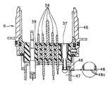
도1에 도시한 바와 같이 내시경 검사를 하는 내시경 장치(1)는 촬상 수단을 구비한 내시경(2)과, 광원 장치(3)와, 비디오 프로세서(5)와, 모니터(6)로 구성되어 있다. 광원 장치(3)는 내시경(2)에 착탈 가능하게 접속되어 내시경(2)에 설치된 라이트 가이드에 조명광을 공급한다. 비디오 프로세서(5)는 내시경(2)과 신호 케이블(4)을 거쳐서 접속되어 내시경(2)의 촬상 수단을 제어하는 동시에 촬상 수단으로부터 얻어진 신호를 처리한다. 모니터(6)는 프로세서(5)로부터 출력되는 피사체 상(像)에 대응하는 영상을 표시한다.As shown in Fig. 1, the
이 내시경(2)은 관찰, 처치 등의 내시경 검사에 사용된 후에는 세정되지만, 그 세척 후에, 고온 고압 증기에 의해 멸균 처리를 하는 것이 가능하도록 고온 고 압 증기에 대한 내성을 구비한 부재로 구성되어 있다. 또한, 이 내시경(2)은 후술하는 바와 같이 내시경(2)의 삽입부(7)나 조작부(8) 등의 외장 부재(외피부)의 내측의 공간부(47)에도 적극적 또는 강제적으로 고온 고압 증기를 유입시켜 멸균 처리를 하는 구조로 하고 있으므로, 내부의 신호선 등도 고온 고압 증기에 대한 내성을 구비한 부재로 구성되어 있는 것이 특징 중 하나로 되어 있다.The
내시경(2)은 가요성을 갖고, 피검체 내, 더욱 구체적으로는 체강 내에 삽입 가능한 가늘고 긴 삽입부(7)와, 삽입부(7)의 기단부 측에 접속된 조작부(8)와, 조작부(8)의 측부로부터 연장된 가요성을 갖는 연결 코드(유니버설 코드)(9)와, 커넥터부(10)와, 전기 커넥터부(11)를 갖고 있다. 커넥터부(10)는 연결 코드(9)의 단부에 마련되어, 광원 장치(3)에 착탈 가능하게 접속된다. 전기 커넥터부(11)는 커넥터부(10)의 측부에 마련되어, 외부 장치인 프로세서(5)에 착탈 가능하게 접속되는 신호 케이블(4)에 있어서의 그 단부의 커넥터(4)를 착탈 가능하게 접속할 수 있게 되어 있다.The
전기 커넥터부(11)에는 내시경(2)의 내부와 외부를 연통하는 통기부(37)가 도4에 도시한 바와 같이 설치되어 있다.In the
삽입부(7)와 조작부(8)의 접속부에는 접속부의 급격한 굴곡을 방지하는 탄성 부재를 갖는 삽입부측 접힘 방지 부재(12)가 설치되어 있다. 조작부(8)와 연결 코드(9)의 접속부에는 마찬가지의 조작부측 접힘 방지 부재(13)가 설치되어 있다. 연결 코드(9)와 커넥터부(10)의 접속부에는 마찬가지의 커넥터부 측 접힘 방지 부재(14)가 설치되어 있다.The insertion part side
삽입부(7)는 가요성을 갖는 유연한 가요관부(15)와, 이 가요관부(15)의 선단부측에 마련되어, 조작부(8)의 조작에 의해 만곡 가능한 만곡부(16)와, 선단부에 마련되어 도시하지 않은 관찰 광학계, 조명 광학계 등이 마련된 선단부(17)로 구성되어 있다.The
선단부(17)에는 송기(送氣) 조작, 송수(送水) 조작에 의해 도시하지 않은 관찰 광학계의 외표면의 광학 부재를 향해 세척 액체나 기체를 분출하기 위한 송기 송수 노즐과, 삽입부(7)에 배치된 처치구를 삽입 관통하거나 체강 내의 액체를 흡인하기 위한 도시하지 않은 처치구 채널의 선단부측의 개구인 흡인구가 설치되어 있다.The
또한, 이 선단부(17)에는 관찰 대상물을 향해 개방한 액체를 분출하기 위한 송액구가 설치되어 있다.Moreover, the
커넥터부(10)에는 광원 장치(3)에 내장된 도시하지 않은 기체 공급원과 착탈 가능하게 접속되는 기체 공급 베이스(21)와, 액체 공급원인 송수 탱크(22)와 착탈 가능하게 접속되는 송수 탱크 가압 베이스(23) 및 액체 공급 베이스(24)가 설치되어 있다. 또한, 커넥터부(10)의 송수 탱크 가압 베이스(23) 및 액체 공급 베이스(24)의 배면측에는, 상기 흡인구로부터 흡인을 하기 위한 도시하지 않은 흡인원과 접속되는 흡인 베이스(25)가 설치되어 있다. 또한, 커넥터부(10)의 흡인 베이스(25)의 근방에는, 송액구로부터 송수를 하기 위한 도시하지 않은 송수 수단과 접속되는 주입 베이스(26)가 설치되어 있다.The
또한, 커넥터부(10)의 측면에는 고주파 처치 등을 행한 때에 내시경에 고주 파 누설 전류가 발생한 경우에 누설 전류를 고주파 처치 장치로 귀환시키기 위한 어스 단자 베이스(27)가 설치되어 있다.In addition, an
조작부(8)에는 송기 조작, 송수 조작을 조작하는 송기 송수 조작 버튼(28)과, 흡인 조작을 조작하기 위한 흡인 조작 버튼(29)과, 상기 만곡부의 만곡 조작을 하기 위한 만곡 조작 노브(30)와, 상기 비디오 프로세서(5)를 원격 조작하는 복수의 리모트 스위치(31), 상기 처치구 채널에 연통한 개구인 처치구 삽입구(32)가 설치되어 있다.The
내시경(2)의 전기 커넥터부(11)에는, 방수 캡(33)을 착탈 가능하게 접속할 수 있다.The
방수 캡(33)에는 도시하지 않은 압력 조정 밸브가 설치되어 있다.The
또, 도1에 도시한 바와 같이 이 내시경(2)은 고압 증기 멸균 시에는, 멸균용 수납 케이스(34)가 이용된다.As shown in Fig. 1, the
이 수납 케이스(34)는, 상부측이 개방되어 멸균 처리하는 내시경(2)을 수납하는 내시경용 트레이로서의 트레이(35)와, 이 트레이(35)의 상부측을 덮는 덮개 부재(36)로 구성되어 있다.This
트레이(35)와 덮개 부재(36)에는 복수의 도시하지 않은 공기 통과 구멍이 마련되어 있고, 그 구멍을 통해 수증기가 투과할 수 있도록 되어 있다. 도2는 이 트레이(35)에 내시경(2)을 수납한 상태를 나타낸다.The
도2에 도시한 바와 같이 트레이(35)에는 내시경(2)의 형상에 대응하여 형성된 홈부 내 즉 오목부 내에 내시경(2)을 그 오목부 형상을 따라서 수납 규제하는 오목부 형상이 형성된 수납 규제부(이하, 규제부라 함)(49)가 형성되어 있다. 예컨대 도2에 있어서의 III-III 단면은 도3과 같이 되어 있다. 이 규제부(49)는 내시경(2) 각각의 부분이 소정의 위치에 수납되도록 각각의 부분보다 조금 큰 오목부 형상으로 형성되어 있다.As shown in Fig. 2, the
도4는 전기 커넥터부(11)의 내측 구조를 나타낸다.4 shows the inner structure of the
전기 커넥터부(11)의 케이싱(46) 내측에 수밀(水密)식으로 부착된 절연제의 지지판(39)에는, 촬상 신호선 및 리모트 스위치(31)의 신호선이 접속되는 복수의 접점 핀(38)이 설치되어 있다.The plurality of contact pins 38 to which the imaging signal line and the signal line of the
또한, 본 실시 형태에 있어서의 내시경(2)의 전기 커넥터부(11)의 지지판(39)에는, 내시경(2)의 내부와 외부를 연통하는 구멍 혹은 개구로서의 통기부(37)가 설치되어 있다. 이 통기부(37)에 의해, 내시경(2)의 외부와, 내시경(2)의 외피부, 즉 외장 부재에 의해 밀폐된 내부의 공간부(47)를 연통하도록 하고 있다. 다시 말하면, 통기부(37)에 의해 내부의 공간부(47)와 내시경(2)의 외부를 연통하는 연통로가 형성된다.In addition, in the
이 통기부(37)의 일부에, 증기는 통과시키지만, 증기보다도 큰 물체는 통과시키지 않는 작은 구멍(48a)을 다수 마련한 필터(48)를 도시한 바와 같이 마련하 도록 해도 좋다. 즉, 연통로를 구성하는 통기부(37)에는 수증기는 통과시키지만, 소정 크기 이상의 물체는 통과시키지 않는 필터(48)가 설치되어 있다.A part of this
본 실시 형태에 관한 내시경(2)은 고온 고압 증기로 멸균 처리할 때에 이 통기부(37)로부터 공간부(47) 내로 고온 고압 증기를 유입시켜, 이 공간부(47)에 연 통하는 송기 송수용 관로 등의 관로의 외측을 고온 고압 증기로 가열함으로써, 단시간에 멸균 처리할 수 있도록 구성되어 있다.In the
방수 캡(33)을 전기 커넥터부(11)에 장착했을 때는 수밀 상태로 장착되므로, 외부의 액체는 접점 핀(38)에 접촉하거나, 통기부(37)로부터 내시경(2)의 내부로 침입하는 일은 없다.Since the
그리고 내시경 검사가 종료되면, 내시경(2)의 세정을 한다. 이때, 내시경(2)의 전기 커넥터부(11)에 방수 캡(33)을 장착하고, 상술한 연통로는 폐색된다. 그 결과, 세정액이 내시경(2)의 내부로 침입하거나, 전기 신호의 접점 핀(38)에 접촉하여 차후에 접점 핀(38)의 표면을 열화시켜, 통전 불량 등이 발생하거나 하는 것이 방지된다.When the endoscope examination is finished, the
세정 공정이 끝나면, 도2의 트레이(35)에 내시경(2)을 소정 형상으로 수납한다. 이때, 커넥터부(10) 주변의 오목부(49a)는 커넥터부(10)의 형상을 따른 오목부로 되어 있으며, 전기 커넥터부(11)로부터 방수 캡(33)을 완전히 제거하지 않으면, 커넥터부(10) 및 전기 커넥터부(11)를 오목부(82a) 내에 수납할 수 없도록 하고 있다.After the cleaning process, the
도5는 내시경(2)의 내부에 내장되어 있는 여러 가지 관로를 개략적으로 나타낸다.5 schematically shows the various conduits embedded in the
관로(40)는 주로 삽입부(7) 내에 있으며, 그 관로 선단부(40a)는 선단부(17)에 있어서 외부에 대하여 개방하고 있으며, 관로 후단부(40b)는 조작부(8)에 있어서 외부에 대하여 개방하고 있다. 관로(40)는 예컨대 처치구 삽입 관통용 혹은 흡 인용의 관로이다.The
관로(41)는 주로 연결 코드(9) 내에 있으며, 그 관로 선단부(41a)는 선단부(17)에 있어서 외부에 대하여 개방하고 있으며, 관로 후단부(41b)는 흡인 베이스(25)에 의해 커넥터부(10)에 있어서 외부에 대하여 개방하고 있다. 관로(41)는 예컨대 흡인용 관로이다.The
관로(42)는 주로 조작부(8) 내에 있으며, 그 관로 선단부는 관로 후단부(40b)와 공통으로, 조작부(8)에 있어서 외부에 대하여 개방하고 있고, 관로 후단부는 관로 선단부(41a)와 공통으로 조작부(8)에 있어서 외부에 대하여 개방하고 있다. 관로(42)는 예컨대 흡인용 관로이다. .The
그리고 관로 후단부(41b)[흡인 베이스(25)]에 도시하지 않은 흡인기로부터의 관로를 접속하여 흡인기로 흡인 조작하여, 관로 선단부(41a), 관로 후단부(40b)를 폐쇄해 두면, 관로(41), 관로(42), 관로(40)라 하는 경로에서 관로 선단부(40a)로부터 흡인을 행할 수 있다.If the pipeline from the suction unit (not shown) is connected to the pipeline
관로(43)는 주로 삽입부(7) 내에 있으며, 그 관로 선단부(43a)는 선단부(17)에 있어서 외부에 대하여 개방하고 있고, 관로 후단부(43b)는 조작부(8)에 있어서 외부에 대하여 개방하고 있다. 관로(43)는 예컨대 선단부(17)의 렌즈면의 세정으로 송기나 송수를 하는 송기 송수용의 관로이다.The
관로(44)는 주로 연결 코드(9) 내에 있으며, 그 관로 선단부는 관로 후단부(43b)와 공통으로, 조작부(8)에 있어서 외부에 대하여 개방하고 있고, 관로 후단부(44b)는 송수 탱크 가압 베이스(23), 기체 공급 베이스(24)에 의해 커넥터부(10)에 있어서 외부에 대하여 개방하고 있다. 관로 후단부(43b)를 막아, 관로 후단부(44b)[송수 탱크 가압 베이스(23), 기체 공급 베이스(24)]로부터 송기 또는 송수를 하면, 관로 선단부(43a)로부터 송기 또는 송수를 할 수 있다.The
관로(45)는 주로 삽입부(7)와 연결 코드(9) 내에 있으며, 그 관로 선단부(45a)는 선단부(17)에 있어서 외부에 대하여 개방하고 있고, 관로 후단부(45b)는 주입 베이스(26)에 의해 커넥터부(10)에 있어서 외부에 대하여 개방하고 있다. 관로(45)는 예컨대 관찰 대상물로 송액하는 전방 송수용의 관로이다.The
이와 같이, 내시경(2) 내에는 양단부가 외부에 대하여 개방하고, 내측에 유체 등을 삽입 관통 가능하게 하는 여러 가지 관로가 내장되어 있다. 게다가, 삽입부(7)와 연결 코드(9)는 모두 유연한 부재로 형성되어, 속이 차 있지 않은 비어 있는 상태이다. 또한, 삽입부(7)와 연결 코드(9) 중의 관로의 대부분은 유연한 움직임에 대응할 수 있도록 중공 부분에 비고정 상태로 배치되고, 관로 주위는 다른 내장물은 있지만, 대부분 공간으로 되어 있다.Thus, in the
내시경(2)의 외피 내측에 있어서, 이들의 관로의 중간 부분(여기서는 단부로부터 이격된 위치라는 의미로, 어느 정도 넓은 범위를 가리킴)에 있어서의 관로의 외측은 주위의 공간부(47)와 연통하고, 이 공간부(47)는 통기부(37)에 의해 외부와 연통하고 있다. 즉, 관로 외측은 공간부(47)와 연통하는, 연통 수단인 통기부(37)를 거쳐서 외부와 연통하는 상태로 되어 있다. 다시 말해서, 내시경(2)의 내부를 삽입 관통하고 있는 각종 관로의 외측과 내시경(2)의 외장 부재에 의해 형성되는 공간부(47)는, 내시경(2)의 외부와 통기부(37)를 거쳐서 연통하고 있다. 그리고 이 통기부(37)에 의한 연통 상태는 방수 캡(33)의 장착/미장착(제거)에 의해 선택할 수 있다.Inside the outer shell of the
본 실시 형태에서는, 예컨대 어떤 관로의 개구부와 개구부를 연결하여의 부분 주변에는, 충전제나 고형물에 의해 내시경(2)의 외피 내측을 충전하는 일없이, 상기 공간부(47)가 형성되는 공간이 확보되어 있다. 또한, 그 공간부(47)와 통기부(37)와의 경로의 도중에도 여러 가지 내장물이나 부품이 존재하지만, 그들은 증기의 길을 차단하지 않도록 배치되어 있다. 따라서 이 경로에 의해 증기는 저해되는 일없이 통과할 수 있다.In the present embodiment, for example, a space in which the
본 실시 형태에 관한 내시경(2)에서는, 통기부(37)를 설치함으로써, 멸균 처리를 하는 경우에, 내시경(2)의 내부에 마련된 각 관로에서의 그 주위의 공간부(47)와 연통시킬 수 있어, 예비 진공 시에 공간부(47)도 예비 진공 상태로 설정할 수 있다. 그 후의 고온 고압 증기 멸균하는 공정에 있어서(관로의 내측은 물론), 관로의 외측의 공간부(47)에도 고온 고압 증기를 빠르게 공급하여 충만 가능하게 하여, 각 관로를 관로의 외측으로부터 가열함으로써, 고온 고압 증기 멸균 처리를 단시간에 종료할 수 있도록 하고 있는 것이 특징으로 되어 있다.In the
이 경우의 작용은 도9 및 도10을 참조하여 후술한다.The operation in this case will be described later with reference to FIGS. 9 and 10.
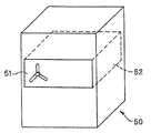
또한, 본 실시 형태에 관한 내시경(2)을 트레이(35)에 수납하여 고온 고압 증기 멸균을 하는 고온 고압 증기 멸균 장치(50)를 도6에 나타낸다.6 shows the high temperature high pressure
이 고온 고압 증기 멸균 장치(50)는, 상자형 형상이며, 그 전방면에 마련한 도어(51)를 개방하면, 그 내측이 고온 고압 증기 멸균을 하는 멸균실이 되는 챔버 (52)로 되어 있으며, 그곳에 내시경(2)을 수납한 트레이(35)를, 혹은 트레이(35)를 덮개 부재(36)로 덮은 멸균용 수납 케이스(34)를 투입하여 도어(51)를 폐쇄하여 멸균 처리를 할 수 있다.This high temperature high pressure
이 챔버(52)의 형상은, 예컨대 내시경(2)을 수납한 멸균용 수납 케이스(34)를 1개만, 빠듯이 넣는 수납 사이즈로 하고 있다.The shape of this
또한, 이 고온 고압 증기 멸균 장치(50)의 일부에, 커넥터부(10)[또는 전기 커넥터부(11)]와 방수 캡(33)의 상대적인 상태를 검지하는 수단을 마련하도록 해도 좋다.In addition, a part of the high temperature high pressure
예컨대 전기 커넥터부(11) 근방과 방수 캡(33)의 각각에 임의의 캡을 마련하여, 고온 고압 증기 멸균 장치(50)에 의해 그들 캡의 거리를 측정함으로써, 전기 커넥터부(11)에 방수 캡(33)이 장착되어 있는지의 여부를 검지할 수 있도록 해도 좋다.For example, an arbitrary cap is provided in the vicinity of the
또, 이 이외의 기구에 의해, 전기 커넥터부(11)에 방수 캡(33)이 장착되어 있는지의 여부를 검지하는 수단을 마련하도록 해도 좋다.In addition, a mechanism for detecting whether the
상기 고온 고압 증기 멸균 장치(50) 등에 의한 고온 고압의 증기 멸균의 대표적인 조건(온도, 시간, 압력)으로서는 미국 규격 협회 승인, 의료기기 개발 협회 발행의 미국 규격 ANSI/AAMI ST37-1992에서는 멸균 공정 전에 감압하는 예비 진공 타입에 있어서는 멸균 공정 132 ℃에서 4분, 멸균 공정 전에 감압하지 않는 그레비티 타입에 있어서는 멸균 공정 132 ℃에서 10분으로 되어 있다.Representative conditions (temperature, time, pressure) of the high temperature and high pressure steam sterilization by the high temperature and high pressure
고온 고압 증기 멸균의 멸균 공정 시의 온도 조건에 대해서는 고온 고압 증 기 멸균 장치의 형식이나 멸균 공정의 시간에 따라 다르지만, 일반적으로는 115 ℃에서 138 ℃ 정도의 범위로 설정된다. 멸균 장치 중에는 142 ℃ 정도로 설정 가능한 것도 있다.The temperature conditions in the sterilization process of high temperature high pressure steam sterilization vary depending on the type of the high temperature high pressure steam sterilization apparatus and the time of the sterilization process, but are generally set in the range of 115 ° C to 138 ° C. Some sterilization apparatuses can be set at about 142 degreeC.
시간 조건에 대해서는 멸균 공정의 온도 조건에 따라 다르지만, 일반적으로는 3분 내지 60분 정도로 설정된다. 멸균 장치의 종류에 따라서는 100분 정도로 설정 가능한 것도 있다.About time conditions, although it changes with the temperature conditions of a sterilization process, it is set generally about 3 to 60 minutes. Depending on the type of sterilization apparatus, it may be set to about 100 minutes.
이 공정에서의 멸균실 내의 압력은 일반적으로는 대기압에 대하여 +0.2 MPa 정도로 설정된다.The pressure in the sterilization chamber in this process is generally set at about +0.2 MPa with respect to atmospheric pressure.
일반적인 예비 진공 타입의 고온 고압 증기 멸균 공정에는 멸균 대상 기기를 수용한 멸균실 내를 멸균 공정 전에 감압 상태로 하는 예비 진공 공정과, 이 후에 멸균실 내에 고온 고압 고온 증기를 보내 멸균을 하는 멸균 공정이 포함되어 있다.The preliminary vacuum type high temperature high pressure steam sterilization process includes a preliminary vacuum process in which a sterilization chamber containing a device to be sterilized is decompressed before sterilization, and a sterilization process which is then sterilized by sending high pressure, high temperature steam into the sterilization chamber. Included.
예비 진공 공정은 다음의 멸균 공정 시에 멸균 대상 기기의 세부에까지 증기를 침투시키기 위한 공정이며, 멸균실 내를 감소시킴으로써 멸균 대상 기기 전체에 고압 고온 증기가 널리 퍼지게 된다.The preliminary vacuum process is a process for infiltrating steam to the details of the sterilization target device during the next sterilization process, and by reducing the inside of the sterilization chamber, the high pressure and high temperature steam is spread widely throughout the sterilization target device.
예비 진공 공정에 있어서의 멸균실 내의 압력은 일반적으로는 대기압에 대하여 -0.07 MPa 내지 0.09 MPa 정도로 설정된다.The pressure in the sterilization chamber in the preliminary vacuum process is generally set at about -0.07 MPa to 0.09 MPa with respect to atmospheric pressure.
멸균 후의 멸균 대상 기기를 건조시키기 위해 멸균 공정 후에 멸균실 내를 다시 감압 상태로 하는 건조 공정이 포함되어 있는 경우가 있다. 이 공정에서는 멸균실 내를 감압하여 멸균실 내로부터 증기를 배제하여 멸균실 내의 멸균 대상 기기의 건조를 촉진한다. 이 공정에서의 멸균실 내의 압력은 일반적으로는 대기압에 대하여 -0.07 내지 -0.09 MPa 정도로 설정된다.In order to dry the sterilization object after sterilization, the drying process may be included in which the inside of the sterilization chamber is reduced again after the sterilization process. In this process, the pressure in the sterilization chamber is reduced to exclude steam from the sterilization chamber to facilitate drying of the sterilization target device in the sterilization chamber. The pressure in the sterilization chamber in this process is generally set at about -0.07 to -0.09 MPa with respect to atmospheric pressure.
본 실시 형태에서는, 후술하는 바와 같이 내시경(2)을 고온 고압 증기 멸균할 때에는 방수 캡(33)을 전기 커넥터부(11)로부터 제거한 상태에서 행한다. 그리고 상술한 바와 같이 내시경(2)에 통기부(37)를 마련해 둠으로써, 단시간에 고온 고압 증기 멸균 처리를 완료할 수 있도록 하고 있다.In the present embodiment, when the
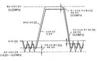
다음에 본 실시 형태에 의한 내시경(2)의 고온 고압 증기 멸균하는 방법을 설명한다. 우선, 고온 고압 증기 멸균 장치(50)에 의해 내시경(2)을 고온 고압 증기 멸균하는 경우의 전체 공정의 일례를 도7에 나타낸다.Next, the high temperature high pressure steam sterilization of the
도7에 도시한 바와 같이, 고온 고압 증기 멸균하는 전체 공정은 예열 공정, 예비 진공 정도, 멸균 공정, 음압 건조 공정으로 이루어진다. 또, 도7에 있어서 실선은 압력 상태를 나타내고, 점선은 온도 상태를 나타내고 있다. 또한, 압력은 대기압의 상태를 0으로 하여, 가압한 경우에는 플러스인 값으로, 음압으로 한 경우를 마이너스인 값으로 나타내고 있다.As shown in FIG. 7, the whole process of high temperature high pressure steam sterilization consists of a preheating process, a preliminary vacuum degree, a sterilization process, and a negative pressure drying process. 7, the solid line shows the pressure state, and the dotted line shows the temperature state. In addition, the pressure is a positive value when the state of atmospheric pressure is 0, and when it pressurizes, and the negative pressure is shown by the negative value.
도7에서는, 예비 진공은 -0.09 내지 -0.07 MPa의 음압에 있어서 3회 행하고 있다. 이 사이, 증기 공급이 이루어져, 온도도 상승한다(도7에서는 매우 거친선으로 개략적으로 나타내고 있음).In Fig. 7, the preliminary vacuum is performed three times at a negative pressure of -0.09 to -0.07 MPa. In the meantime, steam supply is made and temperature rises (it shows schematically in a very rough line in FIG. 7).
멸균 공정에서는, 0.22 MPa의 압력으로 설정하여 135 ℃(온도와 압력은 대응하고 있음)의 온도로 실시하고 있다.In the sterilization step, the pressure is set at a pressure of 0.22 MPa and is performed at a temperature of 135 ° C (temperature and pressure correspond).
또한, 도8은 내시경(2)으로 내시경 검사를 한 후, 세정 작업과 멸균 작업을 행하여 다시 내시경 검사를 할 수 있도록 하는 리프로세스의 공정을 나타낸다.8 shows the process of the reprocessing which allows the endoscopy to be performed again by performing the endoscopy with the
도8에 도시한 바와 같이 단계 S1에 있어서 내시경 검사를 행하고, 내시경 검사가 종료되었다면, 단계 S2에 나타내는 바와 같이 방수 캡(33)을 전기 커넥터부(11)에 장착하여 이 전기 커넥터부(11)를 방수로 하여 내시경(2)의 수밀을 확보한다.As shown in Fig. 8, when the endoscope inspection is performed in step S1, and the endoscope examination is finished, the
그리고 단계 S3 및 단계 S4의 세정 작업(세정 공정)을 한다. 단계 S3에 있어서는 수밀 상태의 내시경(2)을 세정조 등에 삽입하여 내시경(2)의 외표면 및 관로 내의 세정을 한다.And the washing | cleaning operation (washing process) of step S3 and step S4 is performed. In step S3, the
그 후, 단계 S4에 나타낸 바와 같이 세정액의 린스 및 건조가 행해져 세정 작업을 종료한다.Thereafter, as shown in step S4, rinsing and drying of the cleaning liquid are performed to complete the cleaning operation.
이 세정 작업이 종료되었다면 단계 S5에 나타낸 바와 같이 방수 캡(33)을 전기 커넥터부(11)로부터 제거하여, 내시경(2)을 트레이(35)에 수납한다.If the cleaning operation is completed, the
내시경(2)을 트레이(35)에 수납하는 경우, 방수 캡(33)을 제거하지 않으면, 커넥터(10)를 트레이(35)의 규제부(49a) 내에 수납할 수 없으므로, 사용자는 방수 캡(33)을 제거하지 않은 내시경(2)이 다음 단계로 이행하는 데 부적절한 상태인 것을 인식할 수 있다. 이 모습을 도2에 있어서, 방수 캡(33)을 부착한 상태를 2점 쇄선으로 나타내고 있다.When storing the
또한, 가령 사용자가 커넥터(10)가 트레이(35)에 수납되어 있지 않아도 강제적으로 고온 고압 증기 멸균 장치(50)에 투입하려고 한 경우, 챔버(52)의 수납 형상이 내시경(2)을 수납한 멸균용 수납 케이스(34)가 빠듯이 하나 들어가는 형상이면, 커넥터(10)가 수납되지 않고 들려 있어 챔버(52)에 들어가지 않으므로, 그에 의해서도 멸균 작업으로 이행할 수 없는 것을 인식할 수 있다.In addition, when a user tries to forcibly input the high temperature, high pressure
또한, 상술한 바와 같이 고온 고압 증기 멸균 장치(50)에 의해 방수 캡(33)이 전기 커넥터부(11)에 장착되어 있는지의 여부를 검지 수단으로 검지하도록 해도 좋다.As described above, the detection means may detect whether the
이와 같이 하여 내시경(2)을 멸균용 수납 케이스(34)의 트레이(35)에 수납하여, 덮개 부재(36)로 덮는다. 이 후, 단계 S6에 나타낸 바와 같이 내시경(2)을 수납한 멸균용 수납 케이스(34)를, 필팩 등의 멸균용 팩에 수납, 즉 곤포(梱包)한다. 멸균용 팩에의 곤포는 외기 중의 균이 침입할 수 없도록(공기, 수증기는 투과하지만 균이 침입할 수 없음) 확실하게 한다.In this way, the
그리고 단계 S7에서 단계 S10까지의 멸균 작업(멸균 공정)을 한다. 우선, 단계 S7에 있어서는, 트레이(35)[혹은 멸균용 수납 케이스(34)]에 수납 상태인 내시경(2)을 고온 고압 증기 멸균 장치(50)에 투입한다.And the sterilization operation (sterilization process) from step S7 to step S10 is performed. First, in step S7, the
이하의 멸균 작업에 있어서는, 챔버(52)의 공간이 통기부(37)를 거쳐서, 내시경(2)의 내부[더욱 정확하게는 전술한 관로의 중간 부분 주변의 공간부(47)]와 연통하고 있다.In the following sterilization operation, the space of the
고온 고압 증기 멸균 장치(50)에서는, 단계 S9의 고온 고압 증기 멸균 공정으로 진행하기 전에, 단계 S8의 예열 및 예비 진공 공정(음압 공정)이 있다.In the high temperature high pressure
특히 예비 진공 공정에 의해, 챔버(52) 내부 및 내시경(2) 내의 공간부(47)를 음압 상태로 하여, 증기 공급을 하는 동시에 원래의 압력으로 복귀시킨다. 이 프로세스를 최저 한 번 행한다.In particular, by the preliminary vacuum process, the
예비 진공 공정은 복수회 행하는 쪽이, 챔버(52)와 내시경(2) 내의 공간부(47)의 공기가 충분히 빠지기 때문에, 다음 단계 S9의 고온 고압 증기 멸균 공정 시에 챔버(52) 및 내시경(2) 내의 공간부(47)의 공기를 증기로 완전히 치환하기 쉬워져, 바람직하다.Since the pre-vacuum process is carried out a plurality of times, the air of the
이 예비 진공 공정 후에 단계 S9의 고온 고압 증기 멸균을 한다.After this preliminary vacuum process, the high temperature high pressure steam sterilization of step S9 is performed.
이 고온 고압 증기 멸균에 의해 내시경(2)을 고온 고압 증기로 멸균할 수 있다.By this high temperature high pressure steam sterilization, the
이 고온 고압 증기 멸균 후에 단계 S10에 나타낸 바와 같이 음압의 건조 공정(진공에 의한 건조 공정)을 한다.After this high temperature high pressure steam sterilization, a negative pressure drying step (vacuum drying step) is performed as shown in step S10.
이와 같이 음압으로 하여 건조를 하는 공정을 행함으로써, 내시경(2) 내의 공간부(47)로 들어간 증기를 통기부(37)를 거쳐서 외부로 배출 제거할 수 있어, 내시경(2) 내가 물로 젖은 상태가 되는 일이 없고, 또한 내시경(2) 내의 구성 부품의 내구성을 유지할 수 있다. 즉, 녹이나 습기에 의한 열화를 가능한 한 회피할 수 있다. 이로 인해, 음압에 의한 건조를 하는 것이 바람직하다.By performing the process of drying at a negative pressure in this manner, steam entering the
이 건조의 공정을 행한 후에, 고온 고압 증기 멸균 장치(50)로부터 멸균용 팩에 씌워진 내시경(2)을 꺼낸다.After performing this drying process, the
그리고 단계 S11에 나타낸 바와 같이 내시경 검사를 하기 전에 멸균용 팩을 개봉하여 멸균되어 멸균용 수납 케이스(34)에 수납된 내시경(2)을 꺼낸다. 그리고 내시경 검사에 내시경(2)을 사용할 수 있다.Then, as shown in step S11, before the endoscope inspection, the sterilization pack is opened and sterilized and the
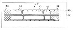
다음에, 통기부(37)를 마련함에 따른 작용 효과를 도9 및 도10을 참조하여 설명한다. 도9는 본 실시 형태에 있어서의 챔버(52) 내에 통기부(37)를 마련한 내시경(2)을 수납한 경우를 개략적으로 나타낸다. 비교를 위해 챔버(52) 내에 통기부(37)를 형성하고 있지 않은 내시경(2')을 수납한 경우를 도10에 나타낸다. 또, 도9 및 도10에 있어서, 실제로는 내시경(2 및 2')은 멸균용 수납 케이스(34)에 수납되고, 또한 증기를 통과시키는 멸균용 팩으로 덮여지지만, 간단화를 위해 생략하고 있다.Next, the effect of providing the
도9에서는 내시경(2)은 통기부(37)에 의해, 내시경(2) 내부의 공간부(47)와 챔버(52) 내의 공간부(52a)가 연통하고 있는 데 반하여, 도10의 내시경(2')에서는 통기부(37)가 마련되어 있지 않으므로, 내시경(2') 내부의 공간부(47)는 챔버(52) 내의 공간부(52a)와 차단되어 있다.In FIG. 9, the
또한 도9 및 도10에 있어서, 내시경(2)은 단부(53, 54)와 그들에 고정된 외피관 부재(55)와, 단부(53, 54)에서 양단부가 개구되어, 외피관 부재(55) 내에 수납된 관로(56)[예컨대 관로(45)를 모의한 것], 공간부(47)로 이루어진다. 도9에서는 단부(54)에 통기부(37)가 설치되어 있다.9 and 10, the
도10의 경우, 공간부(47)는 챔버(52)의 공간부(52a)와는 차단된 밀폐 공간이 되므로, 고온 고압 멸균 공정에 있어서 챔버(52) 내의 공간부(52a)가 고온 고압 증기로 충만되어 있어도 공간부(47) 내부는 압력이 높아지지 않고, 온도도 여간해서는 상승하지 않는다.In the case of Fig. 10, since the
그로 인해, 예비 진공의 공정 후에 관로(56) 내로 증기가 들어가더라도, 그 증기는 관로(56)의 속, 즉 단부(54)로부터 이격된 위치로 갈수록, 증기의 온도는 상승하기 어려워진다. 이것은, 관로(56)의 도중에서 공간부(47)에 의해 온도가 저하되기 쉽기 때문이다. 그로 인해, 멸균을 확실하게 행하기 위해서는, 꽤 긴 시간이 걸릴 우려가 있다.Therefore, even if steam enters the
일반적으로 내시경 검사는, 같은 날에 복수예 실시되는 경우가 많고, 최초의 검사에서 사용한 내시경을 리프로세스하여, 같은 날에 다시, 그리고 몇 번이나 사용하는 경우가 자주 있다. 그때, 가능한 한 빨리 확실하게 리프로세스할 수 있는 것이 요망되고 있다.In general, endoscopy is often performed on the same day in many cases, and the endoscope used in the first inspection is often reprocessed and used again and again on the same day. At that time, it is desired to be able to reliably reprocess as soon as possible.
본 실시 형태에 관한 내시경(2)의 경우에는 도9의 상태가 되어, 통기부(37)가 설치되어 있으므로, 예비 진공 후의 증기 공급으로 증기가 통기부(37)로부터 공간부(47)로 들어간다.In the case of the
따라서, 챔버(52) 내의 공간부(52a)와 공간부(47)는 대략 동등한 압력, 대략 동등한 증기의 존재가 되기 쉬워, 그렇게 되면 관로(56)의 깊은 쪽이라도 관로(56)의 내측은 물론 외측으로부터도 챔버(52)의 공간부(52a)에 충만되는 고온 고압 증기에 의해 마찬가지 레벨의 열을 가할 수 있어, 관로(56) 내의 어떤 위치도 빠르게 멸균이 가능해진다.Therefore, the
또한, 통기부(37)의 중요한 요소는, 그 사이즈에 있다.In addition, an important element of the
가령, 통기부(37)가 공간부(47)의 용적에 대하여 매우 작거나, 또는 가는 것이었다고 하자(예컨대 0.1 ㎜ 등).For example, it is assumed that the
그렇게 되면, 챔버(52) 내의 압력 변화의 속도에 대하여, 공간부(47)를 동기할 수 없어, 시간적인 차이가 생긴다.As a result, the
예비 진공 공정에서는, 챔버(52) 내에서는 예컨대 -0.08 MPa의 상태가 3회 반복하여 행해져도, 공간부(47) 내부는 -0.08 MPa에 달하기 전에, 예컨대 0.03 MPa 정도로, 챔버(52) 내에서는 고온 고압 증기의 압력 상승의 공정으로 들어가는 경우도 있을 수 있다.In the preliminary vacuum step, even if the state of -0.08 MPa is repeatedly performed three times in the
그렇게 되면, 공간부(47) 내부는 충분한 예비 진공을 행하고 있지 않으므로, 원래 공간부(47) 내에 있던 공기가 꽤 남아 증기로의 치환이 불충분해질 수 있다. 이 경우, 챔버(52) 내의 최저 압력 상태를 길게 유지하도록 하면, 공간부(47) 내의 압력도 이윽고 마찬가지의 압력이 되지만, 시간이 지연되는 것은 사용자가 바라는 상태와는 반대의 방향이다.In this case, since the inside of the
고온 고압 증기에 의한 멸균 공정에 있어서도, 챔버(52) 내가 0.22 MPa에 도달해도, 공간부(47) 내부는 여간해서 도달하지 않고 지연되므로, 결국 멸균을 달성하기 위해서는 멸균 시간(최고 온도 상태)을 길게 연장시켜야만 해, 이것도 사용자가 바라는 상태와는 반대의 방향이다.Even in the sterilization process by the high temperature and high pressure steam, even if the inside of the
이상으로부터, 통기부(37)의 사이즈는 공간부(47)의 용적에 대하여 적절한 크기가 바람직하다.From the above, the size of the
예컨대 1 ㎜ 이상, 가능하면 5 ㎜, 10 ㎜로 큰 쪽이 더욱 바람직하다. 또한, 가능하면 통기부(37)에 연통한 내시경(2)의 내부의 공간부(47) 내에서, 가장 간극이 작은 부분의 간극의 면적보다도, 통기부(37)의 면적이 큰 쪽이 통기부(37)가 증기 침입의 난관이 되는 것을 방지할 수 있다.For example, it is more preferable that it is 1 mm or more, if possible, as large as 5 mm and 10 mm. In addition, if possible, in the
이와 같이, 본 실시 형태에서는 예비 진공 공정, 고온 고압 증기 멸균 공정 에 있어서, 챔버(52) 내와 내시경(2) 내의 공간부(47)가 항상 대략 동등한 압력으로 공정이 추이(推移)하도록, 그렇게 되는 내시경(2) 내의 내부 공간의 용적과 통기부(37)의 사이즈를 설정했다. 그렇게 함으로써, 짧은 시간 내에 확실하게 관로 내의 멸균 처리를 할 수 있다.As described above, in the present embodiment, in the preliminary vacuum process and the high temperature and high pressure steam sterilization process, the process is performed so that the
또, 도4에서 도시한 바와 같이 통기부(37)의 일부에, 증기는 통과시키지만, 어느 정도 크기의 물체는 통과시키지 않는 필터(48)가 설치되어 있으면, 내시경(2) 내에서 사용되고 있는 윤활제 등이, 만에 하나 방수 캡(33)을 제거한 상태에서의 멸균 작업 중에 통기부(37)로부터 외부로 나와 버리는 것을 방지할 수 있다. 또, 증기만을 통과시킬 정도의 작은 구멍을 다수 마련한 필터를 부착하도록 해도 좋다.In addition, as shown in FIG. 4, when a
이상 설명한 바와 같이 제1 실시 형태에 따르면, 내시경의 고온 고압 증기 멸균을 할 때, 내시경에 내장된 관로 내의 멸균을 더욱 빠르게 또한 확실하게 행할 수 있다. 또, 간단한 구성으로 관로 내 등의 멸균 처리를 단시간에 행할 수 있다.As described above, according to the first embodiment, when the high-temperature, high-pressure steam sterilization of the endoscope is performed, sterilization in the pipeline embedded in the endoscope can be performed more quickly and reliably. Moreover, the sterilization process of a pipe line etc. can be performed in a short time with a simple structure.
(제2 실시 형태)(2nd embodiment)
다음에 본 발명의 제2 실시 형태를 도11을 참조하여 설명한다.Next, a second embodiment of the present invention will be described with reference to FIG.
제1 실시 형태에서는 전기 커넥터부(11)에 통기부(37)를 마련한 경우로 설명하였다. 본 실시 형태는 통기부(37)를 전기 커넥터부(11) 이외의 부분에 마련하여 개량한 것이다. 제1 실시 형태와 동일한 구성 요소에 대해서는 동일 부호를 붙이고 설명은 생략한다.In 1st Embodiment, it demonstrated the case where the
통기부(37)를 전기 커넥터부(11)에 마련한 경우의 개선해야 할 점을 이하에 열거한다.The points which should be improved when the
(a) 전기 커넥터부(11)[혹은 커넥터부(10)]는, 광원 장치(3)나 프로세서(5)와 접속하는 부분이므로, 삽입부(7)로부터 가장 이격된 위치에 있다. 따라서 통기부(37)가 충분히 크면 좋지만, 통기부(37)를 거쳐서 삽입부(7)에 내장된 관로에 증기가 접촉하기 어렵다.(a) Since the electrical connector portion 11 (or the connector portion 10) is a portion to be connected to the
(b) 제1 실시 형태 중에서도 서술한 바와 같이, 통기부(37)는 가능한 한 큰 쪽이 바람직하다. 그러나 내시경(2)과, 고온 고압 증기 멸균을 할 수 없는 기존의 내시경을 공통적으로 광원 장치(3)나 프로세서(5)에 접속 가능하게 하는 경우(호환성 확보), 내시경(2)의 전기 커넥터부(11)를 종래의 내시경보다 크게 할 수 없다.(b) As described above, among the first embodiments, the
그와 같은 한정된 공간에 통기부(37)를 마련해야만 해, 통기부(37)는 비교적 작은 사이즈로 할 수밖에 없다.The
(c) 도4에서 나타낸 접점 핀(38)의 바로 내측의 공간부(47)는 수많은 배선으로 뒤얽혀 있다. 경우에 따라서는, 그것이 통기부(37)로부터의 증기의 침입을 저해하는 일도 있을 수 있다. 그들의 배선은 전기 커넥터부(11)로부터 조금 이격된 위치에서는 묶여져 1개 혹은 여러 개의 케이블이 된다.(c) The
이들의 점을 고려하여 도11에 나타내는 내시경(2B)에서는, 내시경(2B) 내의 공간부(47)에 연통하는 통기부(37)를, 조작부(8)의 일부에 마련하도록 하고 있다. 이 경우, 통기부(37)에는 수밀 캡(60)을 착탈 가능하게 하고, 또한 이 수밀 캡(60)은 끈 부재(61)에 의해 조작부(8)에 이어져 있도록 하고 있다.In view of these points, in the
이들 통기부(37), 수밀 캡(60)은 파선으로 나타내는 조작부(8)의 후단부 부근에 마련하도록 해도 좋다.These
또, 도11의 내시경(2B)을 멸균용 수납 케이스(34)에 수납하는 경우, 검사 중이나 세정 시에 통기부(37)에 장착하고 있던 수밀 캡(60)을 제거하지 않으면, 내시경(2B)을 멸균용 수납 케이스(34)에 수납할 수 없는 트레이(35)의 형상으로 하고 있다.In addition, when storing the
또한, 통기부(37)와 외부와의 연통 상태를 사용자에게 통지하는 수단을 마련하도록 해도 좋다.In addition, a means for notifying the user of the state of communication between the
본 실시 형태에 따르면, 통기부(37)를 조작부(8)에 마련함으로써, 삽입부(7)에 가까운 부위에 형성할 수 있어, 통기부(37)로부터 침입한 증기를 내시경(2) 내의 공간부(47) 전체에 널리 퍼지게 하기 쉽다.According to this embodiment, by providing the
또한, 수밀 캡(60)을 끈 부재(61)로 연결하도록 함으로써, 수밀 캡(60)을 분실하는 것을 방지할 수 있다.In addition, it is possible to prevent the
도12에 나타내는 본 실시 형태의 변형예의 내시경(2C)에서는, 통기부(37)는 제1 실시 형태와 마찬가지로, 전기 커넥터부(11) 내에 설치되어 있다.In the
이 경우, 그 상태에서는 상술한 (a) 및 (b)의 개선해야 할 점이 남지만, 통기부(37)에 튜브(62)의 일단부(62b)를 접속하고, 연결 코드(9) 내를 삽입 관통하여 다른 쪽의 단부(62a)를 조작부(8)의 내부의 공간부(47)에 연통시키도록 하여, 개선해야 할 점을 거의 해소하고 있다. 즉, 연통로로서 내시경 외부에 개방하는 단부(62b)와, 내시경 내부의 소정의 위치에 마련된 단부(62a)를 연결하는 관로 부재인 튜브(62)가 설치되어 있다.In this case, although the above-mentioned points (a) and (b) have to be improved, one
즉, 이 튜브(62)로 증기 침입로를 형성하고, 튜브(62)에 의해 내시경(2C)의 삽입부(7)로부터 이격된 조작부(8)나 연결 코드(9) 측으로 증기를 침입하기 쉽게 하고, 또한 기존의 내시경의 경우와 마찬가지로 공통의 광원 장치(3)나 프로세서(5)에 접속 가능하게 하고 있다.That is, this
본 변형예에 따르면, 통기부(37)를 조작부(8)에 마련한 경우에 있어서의 조작부(8)의 중량이 증가해 버리는 일도 없고, 기존의 내시경의 경우와 마찬가지의 조작성을 확보할 수 있다.According to this modification, the weight of the
또한, 다른 변형예로서, 통기부(37)를 전기 커넥터부(11)가 아닌 커넥터부(10)에 있어서 전기 커넥터부(11)보다도 조작부(8) 측 근방, 예컨대 흡인 베이스(25)나 주입 베이스(26) 근방에 마련해도 좋다.Moreover, as another modification, the
그렇게 하면 통기부(37)를 비교적 크게 할 수도 있어, 상기 (b), (c)의 개선해야 할 점을 해결할 수 있다.By doing so, the
또 다른 변형예로서, 복수 부위에 통기부를 마련하도록 해도 좋다. 도13은이 경우의 내시경(2D)을 나타낸다.As another modification, you may provide a ventilation part in multiple site | parts. Fig. 13 shows the
이 내시경(2D)에서는 도11에 도시한 바와 같이 조작부(8)에 통기부(37)를 방수 캡(60)으로 덮을 수 있도록 마련하는 동시에, 또한 커넥터부(10)에 있어서의 전기 커넥터부(11) 이외의 부분, 예를 들면 흡인 베이스(25)나 주입 베이스(26) 근방에 통기부(37b)를 마련하도록 하고 있다. 또한, 이 통기부(37b)도 예를 들면 끈 부재(61b)에 접속된 방수 캡(61b)으로 방수할 수 있도록 하고 있다.In the
이와 같이 하나의 내시경(2D)에서의 복수 부위, 예컨대 이격된 복수 부위에 통기부(37, 37b)를 마련하도록 해도 좋다.In this way, the
이와 같이 하면 가늘고 긴 내시경(2D)에서의 가늘고 긴 관로를 그 내측으로부터는 물론, 관로의 외측의 복수 부위의 통기부(37, 37b)로부터 증기 멸균으로 단시간에 고온 상태로 설정한 단시간에서의 멸균을 할 수 있다.In this way, sterilization in a short time in which the elongated pipe in the
이상 설명한 바와 같이 제2 실시 형태에 따르면, 내시경의 고온 고압 증기 멸균을 할 때, 내시경에 내장된 관로 내의 멸균을 더욱 빠르게 또한 확실하게 행할 수 있다.As described above, according to the second embodiment, when the high-temperature, high-pressure steam sterilization of the endoscope is performed, sterilization in the pipeline embedded in the endoscope can be performed more quickly and reliably.
(제3 실시 형태)(Third embodiment)
도14 내지 도24는 본 발명의 제3 실시 형태에 관한 도면이다. 도14는 본 발명의 제3 실시 형태에 관한 내시경을 구비한 내시경 장치의 전체 구성도이다. 도15는 제3 실시 형태에 관한 내시경을 트레이에 수납한 상태를 나타내는 평면도이다. 도16은 제3 실시 형태에 관한 내시경에 마련된 관로 시스템의 구성을 나타내는 도면이다. 도17은 제3 실시 형태에 관한 내시경에 설치된 증기 공급용 역지 밸브의 구조를 그 작용을 설명하기 위한 개략 구성도이다. 도18은 제3 실시 형태에 관한 내시경에 마련된 증기 공급용 역지 밸브의 구조를 그 작용을 설명하기 위한 개략 구성도이다. 도19는 제3 실시 형태에 관한 내시경에 마련된 증기 공급용 온도 밸브의 구조를 그 작용을 설명하기 위한 개략 구성도이다. 도20은 제3 실시 형태에 관한 내시경에 마련된 증기 공급용 온도 밸브의 구조를 그 작용을 설명하기 위한 개략 구성도이다. 도21은 제3 실시 형태에 관한 내시경 검사 후에 재사용할 수 있도록 처리하는 리프로세스 시의 처리 순서를 나타내는 흐름도이다. 도22는 증기 공급용 온도 밸브를 마련한 내시경에 의해 고온 고압 증기 멸균하는 경우의 작용을 설명하기 위한 내시경의 개략도이다. 도23은 종래예에 관한 고온 고압 증기 멸균하는 경우의 작용을 설명하기 위한 내시경의 개략도이다. 도24는 고온 고압 증기 멸균하는 경우에 있어서의 내시경 내부의 공간부의 압력 상태를 나타내는 도면이다.14 to 24 show a third embodiment of the present invention. 14 is an overall configuration diagram of an endoscope apparatus provided with an endoscope according to a third embodiment of the present invention. Fig. 15 is a plan view showing a state where the endoscope according to the third embodiment is stored in a tray. FIG. 16 is a diagram illustrating a configuration of a pipeline system provided in the endoscope according to the third embodiment. FIG. Fig. 17 is a schematic configuration diagram for explaining the structure of the steam supply check valve provided in the endoscope according to the third embodiment. Fig. 18 is a schematic configuration diagram for explaining the function of the structure of the steam supply check valve provided in the endoscope according to the third embodiment. Fig. 19 is a schematic configuration diagram for explaining the function of the structure of a temperature supply valve for steam provided in the endoscope according to the third embodiment. 20 is a schematic configuration diagram for explaining the function of the structure of the temperature supply valve for steam provided in the endoscope according to the third embodiment. Fig. 21 is a flowchart showing a processing sequence at the time of reprocessing to be reusable after endoscopy according to the third embodiment. Fig. 22 is a schematic diagram of an endoscope for explaining the action of high temperature and high pressure steam sterilization by an endoscope provided with a steam supply temperature valve. Fig. 23 is a schematic diagram of an endoscope for explaining the action of high temperature, high pressure steam sterilization according to the prior art. Fig. 24 is a diagram showing the pressure state of the space part inside the endoscope in the case of high-temperature, high-pressure steam sterilization.
또, 제1 실시 형태와 동일한 구성 요소에 대해서는 동일한 부호를 붙여, 설명은 생략하고, 주로 다른 점에 대해 설명한다.In addition, about the component same as 1st Embodiment, the same code | symbol is attached | subjected, description is abbreviate | omitted, and a mainly different point is demonstrated.
우선, 본 실시 형태에 관한 내시경 장치의 구성을 설명한다. 도14는 내시경 장치(1)의 전체 구성을 나타낸다. 도14에 있어서, 방수 캡(33)에는 압력 조정 밸브(33a)가 설치되어 있는 점이 도1과 다르다.First, the structure of the endoscope apparatus which concerns on this embodiment is demonstrated. 14 shows the overall configuration of the
또한, 제3 실시 형태의 내시경(2)에 있어서의 조작부(8)에는, 후술하는 바와 같이 고온 고압의 증기 멸균을 하는 조건하에서, 내시경(2)의 외장체의 내부 공간부에 고온 고압의 증기를 유입시켜 내시경(2)의 내부 공간부를 증기로 가열 멸균하기 위한 증기 공급용 역지 밸브(55) 혹은 증기 공급용 온도 구동 밸브(이하에서는 증기 공급용 온도 밸브라 줄여 기록)(56)가 설치되어 있으며, 증기 공급용 역지 밸브(55)[혹은 증기 공급용 온도 밸브(56)]는 고온 고압 증기의 조건[내시경(2)이 고온 고압 증기의 분위기 속에 있는 조건]에서 밸브가 자동적으로 개방하도록 하고 있다.In addition, the
내시경(2)을 고온 고압 증기 멸균할 때에는 압력 조정 밸브가 달린 방수 캡(33)을 전기 커넥터부(11)에 부착한 상태에서 행한다.When the
이 상태에서는 상기 압력 조정 밸브가 달린 방수 캡(33)의 압력 조정 밸브 (33a)는 폐쇄되고, 상기 통기구가 압력 조정 밸브가 달린 방수 캡(33)에 의해 막혀, 내시경(2)의 내부는 외부와 수밀식으로 밀폐된다.In this state, the
고온 고압 증기로 멸균 처리하는 공정 전에, 예비 진공 공정이 행해지는 경우가 있다. 이 예비 진공 공정에 있어서는, 멸균실 내의 압력이 감소하여 내시경(2)의 내부보다 외부 쪽이 압력이 낮아지는 압력차가 생기면 상기 압력 조정 밸브가 개방되어, 상기 통기구(37)를 거쳐서 내시경(2)의 내부와 외부가 연통하여 내시경(2)의 내부와 멸균실[즉 챔버(52)] 내의 압력에 큰 압력차가 생기는 것을 방지한다. 이에 의해 내시경(2)은 내부와 외부의 압력차에 의해 파손되는 일이 없다.The preliminary vacuum process may be performed before the process of sterilizing by high temperature, high pressure steam. In this preliminary vacuum step, when the pressure in the sterilization chamber decreases and a pressure difference occurs in which the pressure is lower than the inside of the
멸균 공정에 있어서는 멸균실 내가 가압되어 내시경(2)의 내부보다 외부 쪽이 압력이 높아지는 압력차가 생기면 상기 압력 조정 밸브가 폐쇄된다. 이에 의해 고온 고압의 증기는 압력 조정 밸브가 달린 방수 캡(33)과 상기 통기구를 거쳐서는 내시경(2)의 내부로는 적극적으로는 침입하지 않는다.In the sterilization process, the pressure regulating valve is closed when the pressure inside the sterilization chamber is increased and a pressure difference occurs in the outer side than the inside of the
본 실시 형태에 관한 내시경(2)의 내부에 내장되어 있는 여러 가지 관로는, 도5에 도시한 관로와 대략 같지만, 다음의 점이 다르다.Although various pipe | tubes built in the inside of the
본 실시 형태에서는, 내시경(2)의 외피 등의 외장체에 의해 기밀화된 내부의 공간부(47)에 대하여, 예컨대 커넥터부(10)로부터 삽입부(7)의 선단부(17)까지 연장되는 관로의 대략 중앙 부근의 위치가 되는 조작부(8)에, 고온 고압 증기 멸균할 때에 공간부(47)로 유입하여 고온 고압 증기로 (가열) 멸균하기 위한 증기 공급용 역지 밸브(55) 혹은 증기 공급용 온도 (구동) 밸브(56)를 마련함으로써, 고온 고압 증기 멸균하는 조건에 해당하는 경우에는 밸브를 개방하여 외부와 연통하도록 하고 있는 것이 특징으로 되어 있다.In this embodiment, it extends from the
도16에서는 조작부(8)의 후단부 부근에 증기 공급용 역지 밸브(55)[혹은 증기 공급용 온도 밸브(56)]를 마련하고 있다.In FIG. 16, the steam supply check valve 55 (or the steam supply temperature valve 56) is provided in the vicinity of the rear end of the
또, 이 공간부(47)는 전기 커넥터부(11)에 있어서는, 통기구(37)를 지나서 외부에 연통하고 있다. 이로 인해, 이 전기 커넥터부(11)에는 세정 시나 멸균 시에는 압력 조정 밸브가 달린 방수 캡(33)이 부착된다. 방수 캡(33)이 부착된 상태에서는, 공간부(47)는 전기 커넥터부(11)에 있어서는 압력 조정 밸브(33a)를 거쳐서 외부와 연통하는 상태가 된다.In addition, the
증기 공급용 역지 밸브(55) 및 증기 공급용 온도 밸브(56)의 개략 구성을 도17 내지 도20에 나타낸다.17 to 20 show schematic configurations of the steam
도17에 도시한 바와 같이, 조작부(8)의 외표면에는 조작부 외장체(57)에 마련한 개구(57a)가 설치되어 있다. 이 개구(57a)의 내측 내시경(2)의 내부 공간(47) 부분에는 고온 고압 증기 멸균의 가압 공정에서 개방하여, 외부에 연통하는 압력 구동 밸브로서 증기 공급용 역지 밸브(55)가 설치되어 있다. 증기 공급용 역지 밸브(55)의 설치 장소는 내시경(2) 내부의 관로 중간 부분 주변의 공간과 연통하고만 있으면 효과가 있지만, 삽입부(7)의 선단부(17)와 커넥터부(10) 사이의 대략 중앙 부근이 되는 조작부(8)에 설치되는 쪽이 훨씬 효과적이다.As shown in FIG. 17, the
이 증기 공급용 역지 밸브(55)는, 그 단부가 조작부(8) 내부에 고정된 밸브 보유 지지용 프레임(58)에 마련한 구멍에 진퇴 가능하게 통과되어, 수밀 확보용 스프링(59)의 탄성력에 의해, 상단부에 마련한 밸브부(55a)가 개구(57a)에 압접하도록 압박되어 있다. 통상의 상태, 구체적으로는 내시경 검사 중이나 세정 공정 중의 수압에서는 도18에 도시한 바와 같이 증기 공급용 역지 밸브(55)가 개방되어 있지 않아 외부와 차단되고, 공간부(47)는 이 증기 공급용 역지 밸브(55)에 의해 수밀 상태가 확보되어 있다.The steam
그리고 고온 고압 증기 멸균에 의한 가압 공정 시에, 조작부(8)의 내부의 공간부(47)의 압력보다도 챔버(52) 내의 압력이 0.01 MPa 이상 높으면 밸브부(55a)를 압박하여 도17에 도시한 바와 같이 개방되도록 되어 있다. 개방되는 압력차는, 세정 공정 시의 수압(여기서는 0.001 MPa)보다는 높게, 멸균 공정 시의 챔버(52) 내의 최대 압력(여기서는0.2 MPa)보다 낮게 설계해 두면 좋지만, 세정 공정까지는 더욱 확실하게 수밀을 확보하고, 멸균 공정에서는 더욱 길게 개방하기 위해, 0.005 MPa 이상 0.05 MPa 이하인 것이 더욱 바람직하다.In the pressurization process by high temperature and high pressure steam sterilization, if the pressure in the
또한, 고온 고압 증기 멸균에 의한 때에, 증기 공급용 역지 밸브(55)와 마찬가지의 효과를 얻을 수 있는 고온 고압 증기 멸균 시의 그 온도로 밸브가 개방되면 온도 구동 밸브로서의 증기 공급용 온도 밸브(56)를 도19 및 도20에 나타낸다.In addition, when the valve is opened at the temperature at the time of high temperature high pressure steam sterilization which can obtain the same effect as the steam
이 증기 공급용 온도 구동 밸브(56)는 증기 공급용 역지 밸브(55)의 구조에 있어서, 또한 SMA(형상 기억 합금) 스프링(60)을 마련한 구조이다.This steam supply
즉, 증기 공급용 역지 밸브(55)에 있어서는, 밸브 보유 지지용 프레임(58)과 조작부 외장체(57) 사이에 배치된 수밀 확보용 스프링(59)에 의해, 증기 공급용 역지 밸브(55)는 개구(57a) 측으로 압박되고 있지만, 증기 공급용 온도 구동 밸브(56)에서는 또한 밸브 보유 지지용 프레임(58)보다 아래쪽(내측)에 배치된 SMA 스 프링(60)에 의해 수밀 확보용 스프링(59)에 의한 압박 방향과 반대측으로 압박하고 있다.That is, in the steam
수밀 확보용 스프링(59)의 탄성력에 의해 통상의 상태, 즉 내시경 검사 중이나 세정 공정 중의 수압에서는 증기 공급용 온도 구동 밸브(56)가 개방되어 있지 않고 도19의 상태를 유지하고 있다.By the elastic force of the
한편, 고온 고압 증기 멸균 공정에서는 SMA 스프링(60)은 수밀 확보용 스프링(59)의 탄성력 이상의 복원력(탄성력)을 발휘한다.On the other hand, in the high temperature high pressure steam sterilization process, the
예컨대 온도가 75 ℃ 이상이 되면, SMA 스프링(60)은 수밀 확보용 스프링(59)의 탄성력 이상의 복원력을 발휘하여, 도20에 도시한 바와 같이 증기 공급용 온도 구동 밸브(56)가 개방되도록 되어 있다. 개방되는 만큼의 복원력을 발휘하는 온도 조건은 세정 공정 시의 수온(예컨대 65 ℃)보다는 높고, 멸균 공정 시의 챔버(52) 내의 최고 온도(예컨대 135 ℃)보다는 작으면 좋지만, 세정 공정까지는 보다 확실하게 수밀을 확보하여, 멸균 공정에서는 더욱 길게 개방하기 위해, 70 ℃ 이상 100 ℃ 이하가 더욱 바람직하다. 도20에서는 75 ℃로서 나타내고 있다. SMA로서는, 예컨대 Ni-Ti 합금을 이용할 수 있다.For example, when the temperature is 75 ° C. or higher, the
또, 증기 공급용 역지 밸브(55)나 증기 공급용 온도 밸브(56)의 증기 경로에는 수증기는 통과시키지만, 어느 정도 이상의 크기의 물체는 통과시키지 않는 도시하지 않은 필터를 구비해도 좋다.The steam path may be provided with a filter (not shown) that allows water vapor to pass through the steam
고온 고압 증기 멸균 장치(50)에서 행해지는 일련의 공정은, 상술한 도7과 마찬가지이므로, 설명은 생략한다.Since a series of processes performed by the high temperature high pressure
또, 이하의 도21에 있어서 설명한 바와 같이 내시경 검사가 끝나면 내시경(2)의 세정을 하게 된다. 이때, 내시경(2)의 전기 커넥터부(11)에는, 압력 조정 밸브가 달린 방수 캡(33)을 장착하여, 세정액이 내시경(2)의 내부로 침입하거나, 전기 신호의 접점 핀(38)에 접촉하여 차후에 표면을 열화(통전 불량 등)시키거나 하지 않도록 한다. 세정 공정이 끝나면, 트레이(35)에 내시경(2)을 소정 형상으로 수납하여, 멸균 공정으로 이행한다.As shown in FIG. 21 below, when the endoscope examination is finished, the
또한, 압력 조정 밸브가 달린 방수 캡(33)의 압력 조정 밸브(33a)의 통기로에는, 수증기는 통과시키지만, 어느 정도 이상의 크기의 물체는 통과시키지 않는 도시하지 않은 필터를 마련하도록 해도 좋다.In addition, you may provide the filter which is not shown in the passage of the
다음에 본 실시 형태의 작용을 도21을 참조하여 설명한다. 도21은 내시경(2)의 리프로세스 시에 행해지는 각 단계의 상세를 나타낸다.Next, the operation of the present embodiment will be described with reference to FIG. Fig. 21 shows details of each step performed at the time of reprocessing the
단계 S11에 나타낸 바와 같이 내시경(2)에 의해 내시경 검사를 하고, 이 내시경 검사를 종료한 경우에는 단계 S12에 나타낸 바와 같이 압력 조정 밸브(33a)가 달린 방수 캡(33)을 전기 커넥터부(11)에 장착하여 내시경(2)의 수밀을 확보한다. 그 후, 단계 S13 및 S14의 세정 작업(세정 공정)을 한다.As shown in step S11, the endoscope inspection is carried out by the
우선, 단계 S13에서 내시경(2)의 외표면 및 관로 내의 세정을 하고, 그 후에 단계 S14의 세정액의 린스 및 건조를 한다.First, in step S13, the outer surface of the
단계 S13 및 S14의 세정 작업이 끝나면, 단계 S15에 나타낸 바와 같이 압력 조정 밸브가 달린 방수 캡(33)을 장착한 채로 내시경(2)을 트레이(35)에 수납한다.When the cleaning operation of steps S13 and S14 is finished, the
계속해서, 단계 S16에 나타낸 바와 같이 내시경(2)을 수납한 트레이(35)를, 필팩 등의 멸균 팩에 수납한다.Then, as shown in step S16, the
그 후, 멸균 팩에 수납한 내시경(2)을 도6에 나타내는 고온 고압 증기 멸균 장치(50)에 투입하고(단계 S17), 단계 S17 내지 S20의 멸균 작업(멸균 공정)을 한다.Then, the
이때, 사용자는 내시경(2)에 대해서는 특별한 작업은 아무것도 하지 않고, 단지 장소를 옮길 뿐이므로, 더욱 빠르게 멸균으로 이행할 수 있어, 오작업에 의해 이 후의 멸균이 불충분해지는 경우도 없다.At this time, the user does nothing for the
고온 고압 증기 멸균 장치(50)에 의해, 단계 S19의 고온 고압 증기 멸균을 하기 전에 단계 S18의 예비 진공(음압)의 처리를 한다.By the high temperature high pressure
이 예비 진공의 단계에서는, 챔버(52) 내부를 음압으로 하여 고온 고압 증기의 공급과 함께 원래의 압력으로 복귀시킨다.In this preliminary vacuum step, the inside of the
이때, 압력 조정 밸브(33a)가 있으므로, 내시경(2) 내부도 챔버(52) 내와 함께 음압이 된다.At this time, since there is a
이 프로세스를 최저 한 번 행한 후, 챔버(52) 및 내시경(2) 내의 공간부(47)를 가압하여 증기 멸균의 공정을 한다.After this process is performed at least once, the
또, 예비 진공 공정은 복수회 행하는 쪽이 챔버(52) 및 내시경(2) 내의 공간부(47)의 공기를 충분히 뺄 수 있으므로, 다음 단계 S19의 고온 고압 증기 멸균 공정 시에 증기로 치환하기 쉬워 바람직하다.In addition, since the pre-vacuum process is able to remove the air of the
고온 고압 증기 멸균 후는 단계 S20의 진공(음압)의 건조 공정이 있는 것이 바람직하다.After high temperature high pressure steam sterilization, it is preferable that there exists a drying process of the vacuum (negative pressure) of step S20.
이 건조 공정에 의해, 내시경(2) 내의 공간부(47)로 들어간 증기를, 압력 조정 밸브(33a)를 통해 제거할 수 있어, 내시경(2) 내에 습기가 남는 일이 없어, 내시경(2) 내의 구성 부품의 내구성을 유지할 수 있다. 따라서 녹이나 습기에 의한 열화를 가능한 한 회피할 수 있다. 그리고 내시경(2)을 고온 고압 증기 멸균 장치(50)로부터 꺼낸다.By this drying process, steam which entered the
고온 고압 증기 멸균 장치(50)로부터 꺼낸 내시경(2)을 내시경 검사에 사용하기 전에, 단계 S21에 나타낸 바와 같이 멸균용 팩을 개봉하여 꺼낸다. 그리고 내시경 검사에 사용할 수 있다.Before using the
다음에, 도22와 도23을 참조하여 증기 공급용 역지 밸브(55) 혹은 증기 공급용 온도 밸브(56)에 의한 작용을 설명한다.Next, the operation by the steam
도22는 챔버(52) 내의 내시경(2)의 구성을 개략적으로 나타내고, 비교를 위해 도23은 종래예에서의 챔버(52) 내의 내시경(2')의 구성을 개략적으로 나타낸다. 도22에서는, 증기 공급용 역지 밸브(55)에 의해 내시경(2) 내부의 공간부(47)와 챔버(52) 내가 연통하고 있는 모습을 나타낸다. 증기 공급용 온도 구동 밸브(56)의 경우는 증기 공급용 역지 밸브(55)를 그대로 증기 공급용 온도 구동 밸브(56)로 바꿔 읽으면 된다.22 schematically shows the configuration of the
이 도23에 나타내는 내시경(2')에서는 단부(61, 62)와 그들에 고정된 외피관 부재(63a, 63b)와, 단부(61, 62)에서 양단부가 개방되어, 외피관 부재(63a, 63b) 내에 수납된 관로(64)[예컨대 관로(45)를 모의한 것], 공간부(47), 관로(64)의 중간 부분 부근에서 2개의 외피관 부재(63a, 63b)를 연결하는 접속부(65)[조작부(8) 를 모의한 것]로 이루어진다.In the endoscope 2 'shown in FIG. 23, the
도22에 나타내는 내시경(2)에서는, 도23의 구성에 있어서, 단부(62)에 압력 조정 밸브(33a)가 마련되어 있으며, 또한 연결부(65)에 증기 공급용 역지 밸브(55)가 설치되어 있다. 환언하면, 도23에 나타내는 종래예의 내시경(2')에서는 증기 공급용 역지 밸브(55) 혹은 증기 공급용 온도 구동 밸브(56)가 없고, 고온 고압 증기 멸균 공정에 있어서는 내시경(2')이 수밀 상태로 밀폐된 상태가 된다.In the
도23의 상태에서는, 공간부(47)는 챔버(52)와는 다른 밀폐 공간이므로, 고온 고압 멸균 공정에 있어서도 챔버(52) 내에 대하여 공간부(47) 내부는 압력이 높아지지 않아, 온도도 여간해서 오르지 않는다.In the state of FIG. 23, since the
그로 인해, 예비 진공 후에 관로(64) 내로 증기가 들어가더라도, 그 증기는 공간부(47)의 속, 즉 단부(61)와 단부(62)로부터 이격된 위치, 예컨대 연결부(65)의 내부 근처로 갈수록, 증기의 온도는 상승하기 어려워진다. 이것은, 관로(64)의 도중에서 공간부(47)로 인해 온도가 저하되기 쉽기 때문이다. 그로 인해, 멸균을 확실하게 행하기 위해서는, 꽤 긴 시간이 걸릴 우려가 있다.Therefore, even if steam enters the
일반적으로, 내시경 검사는 같은 날에 복수예가 실시되는 경우가 많아, 최초의 검사에서 사용한 내시경을 리프로세스하여, 같은 날에 두 번, 그리고 몇 번이나 사용하는 일이 자주 있다. 그때, 가능한 한 빨리 확실하게 리프로세스할 수 있는 것이 요망되고 있다.In general, endoscopic examinations are often performed on the same day, and the endoscopy used in the first examination is often accessed by re-processing the endoscope used in the first examination twice and several times on the same day. At that time, it is desired to be able to reliably reprocess as soon as possible.
본 실시 형태의 내시경(2)에 있어서의 도22의 작용을 설명한다. 압력 조정 밸브(33a)와 증기 공급용 역지 밸브(55)가 설치되어 있으므로, 공간부(47) 내의 압 력은 도24와 같은 거동이 된다.The operation of Fig. 22 in the
우선, 예비 진공 공정에 의해, 압력 조정 밸브(33a)로부터 공간부(47) 내의 공기가 빠져 음압이 되므로, 예비 진공 공정 후의 멸균 공정일 때에 증기 공급용 역지 밸브(55)로부터 증기가 더욱 들어가기 쉬워진다.First, since the air in the
계속해서, 가온/가열(증기 공급)의 공정에서, 증기가 증기 공급용 역지 밸브(55)로부터 공간부(47)로 들어간다. 증기 공급용 역지 밸브(55)는 관로(64)의 중간부에 가까운 연결부(65)에 설치되어 있으므로, 증기 공급용 역지 밸브(55)로부터 들어간 증기가 공간부(47) 전체로 널리 퍼지기 쉬워진다.Subsequently, in the heating / heating (steam supply) process, steam enters the
따라서 챔버(52) 내와 공간부(47)는 대략 동등한 압력, 대략 동등한 증기의 존재가 되기 쉽고, 그렇게 되면 관로(64)의 내측이라도, 연결부(65)의 밖에서도 챔버(52) 내와 마찬가지의 레벨로 열을 가할 수 있어, 연결부(65) 내의 어떤 위치라도 빠른 멸균이 가능해진다. 또한, 압력 조정 밸브(33a)의 통기로 및 증기 공급용 역지 밸브(55), 증기 공급용 온도 구동 밸브(56)의 중요한 요소로서, 그 증기 경로의 사이즈가 있다.Therefore, the inside of the
가령, 압력 조정 밸브(33a)의 통기로의 증기 경로가 공간부(47)의 용적에 대하여 대우 작은 것이었다고 하자(예컨대 ø 0.1 ㎜의 경로 등). 그렇게 되면, 챔버(52) 내의 압력 변화의 속도에 대하여, 공간부(47)를 동기할 수 없어 시간적인 차이가 생긴다.For example, it is assumed that the vapor path of the
예비 진공 공정에서는, 챔버(52) 내에서는 예컨대 -0.08 MPa의 상태가 3회 반복하여 행해져도, 공간부(47) 내부는 예컨대 -0.03 MPa까지밖에 내려가지 않는 동안에, 챔버(52) 내에서는 압력 상승의 공정으로 들어가는 일도 있을 수 있다.In the preliminary vacuum process, even if the state of -0.08 MPa is repeatedly performed three times in the
그렇게 되면, 공간부(47) 내부는 충분한 예비 진공을 행하고 있지 않으므로, 원래 공간부(47) 내에 있던 공기가 많이 남아, 증기로의 치환이 불충분해질 수 있다.In this case, since the inside of the
이 경우, 챔버(52) 내의 최저 압력 상태를 길게 유지하도록 하면, 공간부(47) 내의 압력도 이윽고 최저까지 내려가지만, 시간이 지연되는 것은 사용자가 바라는 상태와는 반대의 방향이다.In this case, if the minimum pressure state in the
가온/가압 공정이나 멸균 공정에 있어서도 마찬가지로, 증기 공급용 역지 밸브(55)나 증기 공급용 온도 구동 밸브(56)의 증기 경로가 매우 작은 경우에는, 챔버(52) 내가 0.22 MPa까지 도달해도, 공간부(47) 내부는 여간해서 도달하지 않아 지연되므로, 결국 멸균을 달성하기 위해서는 멸균 시간(최고 온도의 상태)을 길게 연장시켜야만 해, 이것도 사용자가 바라는 상태와는 반대의 방향이다.Similarly, in the heating / pressing process or the sterilization process, if the vapor path of the steam
이상으로부터, 압력 조정 밸브(33a) 및 증기 공급용 역지 밸브(55), 증기 공급용 온도 구동 밸브(56)의 증기 경로는, 공간부(47)의 용적에 대하여 충분한 크기가 필요하다.As mentioned above, the steam path of the
예컨대 ø 1 ㎜ 이상, 가능하면 ø 5 ㎜, ø 10 ㎜로 큰 쪽이 더욱 바람직하다.For example, the larger one of
가능하면, 압력 조정 밸브(33a) 및 증기 공급용 역지 밸브(55), 증기 공급용 온도 구동 밸브(56)에 연통하는 내시경(2) 내부의 공간부(47) 내에서, 가장 간극이 작은 부분의 간극 면적보다도, 압력 조정 밸브(33a) 및 증기 공급용 역지 밸브 (55), 증기 공급용 온도 구동 밸브(56)의 경로 면적이 큰 쪽이, 압력 조정 밸브(33a) 및 증기 공급용 역지 밸브(55), 증기 공급용 온도 구동 밸브(56)가 경로의 난관이 되는 것을 막을 수 있다.If possible, the smallest gap in the
이와 같이, 본 실시 형태에서는 예비 진공 공정, 고온 고압 증기 멸균 공정에 있어서, 챔버(52) 내와 내시경(2) 내의 공간부가 항상 대략 동등한 압력으로 공정이 추이하도록 하였다. 그렇게 함으로써, 가능한 한 짧은 시간에 확실하게 관로 내의 멸균을 실시할 수 있다.As described above, in the present embodiment, in the preliminary vacuum step and the high temperature and high pressure steam sterilization step, the process part is always changed to a pressure approximately equal to the space in the
또, 압력 조정 밸브(33a)나 증기 공급용 역지 밸브(55), 증기 공급용 온도 구동 밸브(56)의 증기 경로에 수증기는 통과시키지만, 어느 정도 크기의 물체는 통과시키지 않는 필터가 있으면, 내시경(2) 내에서 사용되고 있는 윤활제나 먼지 등이 만에 하나라도 멸균 작업 중에 내시경 내로부터 외부로 나오는 일은 없다.In addition, if there is a filter that allows water vapor to pass through the steam path of the
따라서 본 실시 형태에 따르면, 내시경(2)에 내장된 관로 내의 멸균을, 더욱 빠르고 확실하게 행할 수 있다.Therefore, according to this embodiment, sterilization in the pipeline built in the
(제4 실시 형태)(4th embodiment)
다음에 본 발명의 제4 실시 형태를 도25 내지 도27을 참조하여 설명한다. 제3 실시 형태에서는, 증기 공급용 역지 밸브(55) 혹은 증기 공급용 온도 구동 밸브(56)를 마련함으로써, 고온 고압 증기 멸균 시에 내시경(2) 내부로 고온 고압 증기를 유입시켜 내부의 공간부(47)를 증기로 과열 멸균할 수 있도록 하고 있었지만, 본 제4 실시 형태에서는 발열하여 관로를 가열하는 장치를 마련했다.Next, a fourth embodiment of the present invention will be described with reference to Figs. In the third embodiment, by providing the steam
도25는 제4 실시 형태에 관한 내시경(2B) 및 이 내시경(2B)에 내장된 발열 장치(71)의 구성을 개략적으로 나타낸다. 도22와 대략 마찬가지로 이 내시경(2B)에서는 단부(61, 62)와 그들에 고정된 외장 부재인 외피관 부재(63)와, 단부(61, 62)에서 양단부가 개방되어 외피관 부재(63) 내에 수납된 관로(64)에 의해, 내시경(2B)의 내부에 외부와 차단된 공간부(47)가 형성되어 있다. 도25에서는, 도22와 도23에 있어서의 외피관 부재(63a, 63b) 및 연결부(65)는 외피관 부재(63)로 대표되고 있다. 또한, 단부(62)에는 압력 조정 밸브(33a)가 부착되어 있다.Fig. 25 schematically shows the configuration of the
본 실시 형태에서는, 공간부(47) 내에 발열 장치(71)를 수납하고 있다. 이 발열 장치(71)는 전열선(72), 회로 전원(73), 스위치(74)를 포함한 전기 회로(75)로 이루어진다.In the present embodiment, the
스위치(74)가 오프(OFF) 시에는, 상기 회로(75)는 스위치(74)에 의해 차단되어 있지만, 스위치(74)가 온(ON) 상태에서 상기 회로(75)에 전원(73)으로부터의 전류가 흘러, 전열선(72)이 발열한다.When the
스위치(74)는 평온 시에는 오프로 되어 있지만, 열이 나게 되면 온으로 바뀌는 구조로 되어 있다.The
도26 및 도27에 도시한 바와 같이 스위치(74)는, 고온에 반응하여 형상이 변하는 형상 기억 합금 스프링[이후 SMA 스프링(76)]으로 이루어지며, 통상의 평온 시에는 도26에 나타내는 SMA 스프링(76)은 전열선(72)에 접속된 접점(77)과 이격된 상태가 되어 오프이다.As shown in Figs. 26 and 27, the
그리고 고온이 되면, SMA 스프링(76)의 형상이 변화됨으로써 도27에 도시한 바와 같이 접점(77)에 접촉하여 온으로 바뀐다. 여기서는, SMA 스프링(76)의 예로 서 NiTi 합금을 채용하고 있다.When the temperature is high, the shape of the
이 스위치(74)는, 세정 공정 시의 수온(예컨대 65 ℃)보다는 높고, 멸균 공정 시의 챔버(52) 내의 최고 온도 예컨대(135 ℃)보다도 작은 온도에서 온이 되도록 할 수 있으면 좋지만, 세정 공정까지는 더욱 확실하게 수밀을 확보하고, 멸균 공정에서는 더욱 길게 개방하기 위해, 70 ℃ 이상 100 ℃ 이하의 온도에서 온이 되는 것이 더욱 바람직하다. 여기서는, 75 ℃ 이상에서 온이 되도록 설정되어 있다.The
발열 장치(71)는 내시경(2B)의 내부 전체에 배치되어도 좋고, 또한 일부라도 좋다. 일부인 경우는, 관로의 중간부 부근에 배치시키는 것이 바람직하다.The
다음에 본 실시 형태에 있어서의 작용을 설명한다.Next, the operation in the present embodiment will be described.
고온 고압 증기 멸균 공정에 있어서, 피멸균물은 증기에 직접 접촉함으로써 가열되어, 멸균된다. 내시경(2B)의 외표면은 증기가 직접 접촉하기 때문에 가열되기 쉽지만, 관로(64)와 내시경(2B)의 외표면에 의해 둘러싸인 공간부(47)는, 밀폐 공간으로 되어 있으므로 증기가 들어가 있지 않아 가열되기 어렵다. 그로 인해, 공간부(47)의 온도(1)는 직접 증기가 접촉하는 부분과 비교하여 온도의 상승이 늦어진다.In the high temperature high pressure steam sterilization process, the sterilized substance is heated and sterilized by direct contact with steam. The outer surface of the
한편, 내시경(2B) 내부의 관로(64)의 단부(61, 62)는 내시경(2B) 외부의 공간에 대하여 개방되어 있으므로, 관로(64) 내로 증기는 진입해 간다. 그러나 관로(64) 주변에 위치하는 공간부(47)의 온도의 상승이 지연되므로, 관로(64)로 진입한 증기의 열이 공간부(47)로 확산되어 버려, 관로(64) 내의 온도는 상승하기 어려워진다. 그로 인해, 관로(64) 내부는 멸균에 시간이 걸리기 쉬워진다.On the other hand, since the
여기서, 내시경(2B) 내부에 발열 장치(71)를 내장한 경우에 대해 서술한다.Here, the case where the
발열 장치(71)는 고온 고압 멸균 공정 시에 받는 열에 의해 발열하는 구조로 되어 있다.The
그리고 상술한 바와 같이, 75 ℃ 이상의 온도가 되면, 발열 장치(71)의 스위치(74)가 온이 되어, 발열 장치(71)가 발열을 시작한다. 발열 장치(71)에서 발하는 열은 공간부(47)를 가열하여 온도를 올린다.As described above, when the temperature reaches 75 ° C or higher, the
공간부(47)의 온도가 오르면, 관로(64)로 진입한 증기의 열이 공간부(47)로 확산되기 어려워지거나, 혹은 공간부(47)의 온도가 관로(64) 내의 온도보다도 높아지는 경우, 증기에다가 공간부(47) 중의 열에 의해서도 관로(64)를 가열할 수 있다. 그 결과, 관로(64) 내부는 온도가 상승하기 쉬워져, 빠르게 멸균하기 쉬워진다.When the temperature of the
멸균 공정이 끝나면, 증기에 의한 가열이 종료되어 내시경(2B) 주변의 공간온도가 내려간다. 그에 수반하여, 공간부(47)의 온도가 내려가, 발열 장치(71)도 냉각된다. 발열 장치(71)가 냉각되어, 스위치(74)의 절환 온도 이하가 되면, 스위치(74)가 오프가 되어 발열 장치(71)는 발열을 멈춘다.At the end of the sterilization process, heating by steam is terminated and the space temperature around the
광범위에 걸쳐 가열한 쪽이 보다 효율적으로 멸균을 할 수 있으므로, 발열 장치(71)는 내시경(2B)의 내부 전체에 배치되는 것이 가장 바람직하다. 그러나 내시경(2B)에의 내장물이 증가하면 내시경(2B)이 대형화된다고 하는 단점이 있으므로, 내시경(2B) 내부에의 내장물은 가능한 한 적은 쪽이 좋다. 그래서 발열 장치(71)를 내시경 내의 일부에만 마련하여 효과를 발휘하는 방법으로서 이하와 같은 같은 것도 생각할 수 있다.Since the one heated over a wide range can be sterilized more efficiently, it is most preferable that the
고온 고압 증기 멸균에 있어서는, 관로(64)의 개구부로부터 멀어질수록, 즉 관로(64)의 속으로 갈수록 증기가 접촉하기 어려워, 멸균에 시간이 걸린다. 따라서 발열 장치(71)는 관로(64)의 개구부로부터 이격된 위치, 즉 관로의 중간부 부근에 배치시키는 것이 바람직하다.In the high temperature and high pressure steam sterilization, the farther the steam is from the opening of the
따라서 본 실시 형태에 따르면, 내시경(2B)에 내장된 관로(64) 내의 멸균을 더욱 빠르게 확실하게 행할 수 있다.Therefore, according to this embodiment, sterilization in the
(제5 실시 형태)(5th embodiment)
도28은 제5 실시 형태에 관계되는 내시경(2C) 및 발열 장치(71C)의 구성을 개략적으로 나타낸다. 이 발열 장치(71C)는 도25의 발열 장치(71)에 있어서, 스위치(74) 대신에 스위치(74C)를 채용한 구성이다.28 schematically shows the configuration of the
발열 장치(71C)의 구조는, 그 스위치(74C)를 제외한 부분의 구조 이외는 도25와 동등하다.The structure of the
스위치(74C)는 평압 시에는 오프로 되어 있지만, 내시경(2C)이 평상보다도 높은 압력을 받으면 온으로 바뀌는 구조로 되어 있다.The
스위치(74C)는 내시경(2C)의 구성부에 있어서 경질 부재로 덮인 외표면(78), 예컨대 내시경(2C)의 조작부(8)나 커넥터부(10)에 배치시키고 있다.The
도29 및 도30은 스위치(74C)의 구성을 나타낸다.29 and 30 show the configuration of the
스위치(74C)는 정상부가 내시경(2C)의 외표면(78)의 개구에 노출된 스위치 헤드(79), 스위치 헤드(79)에 고정된 전도체의 스위치 막대(80), 스위치 막대(80) 를 지지하는 스위치 누름부(81), 스위치 헤드(79)와 스위치 누름부(81) 사이에 위치하는 스프링(83)으로 이루어진다.The
스위치 헤드(79)는 그 주변에 위치하는 조작부(8) 혹은 커넥터부(10)의 외표면(78)과의 경계에 있어서 수밀을 유지하여, 수밀을 유지한 채로 슬라이드한다.The
스위치 헤드(79)는, 그 정상부에 가해지는 압력에 의해 압입되려고 하지만, 스위치 헤드(79)를 압입하는 힘보다도 스프링(83)의 탄성력이 큰 경우, 스위치 막대(80)는 회로를 형성하는 접점(77)으로부터 분리하여, 스위치(74C)는 도29에 도시한 바와 같이 오프의 상태로 되어 있다.Although the
그러나 고온 고압 증기 멸균 공정 시에 스위치 헤드(79)의 정상부에 고압이 걸려, 스위치 헤드(79)를 압입하는 힘이 스프링(83)의 탄성력보다도 커지면, 스위치 헤드(79)와 함께 스위치 막대(80)가 압입되어, 스위치 막대(80)가 회로를 구성하는 접점(77)에 접촉하여, 도30에 도시한 바와 같이 스위치(74C)가 온이 된다.However, when the high pressure is applied to the top of the
발열 장치(71C)는 탄성력이 다른 스프링(83)을 사용하거나 혹은 외표면(78)과 스위치 누름부(81)와의 간격을 조정함으로써, 스위치(74C)가 온이 될 때의 압력을 조절할 수 있다.The
고온 고압 멸균 공정 시 이외에 스위치(74C)가 온이 되지 않도록, 스위치(74C)가 온이 될 때의 압력은 고온 고압 증기 멸균 이외의 공정 중에 걸리는 일이 없는 압력, 예컨대 0.3 kgf/ ㎠로 설정하면 좋다.When the
또한, 스위치(74C)는 고온 고압 증기 멸균의 설정 압력 이하의 압력으로 온이 될 필요가 있다.In addition, the
회로에 통전했을 때에, 회로 전류가 릴리프하지 않도록 스위치 헤드(79) 및 스위치 누름부(81)는 절연체일 필요가 있다.When energizing the circuit, the
고온 고압 멸균 공정 시 이외에, 다른 물체와의 접촉에 의해 스위치 헤드(79)가 압입되어 스위치(74C)가 온이 되는 일이 없도록, 스위치 헤드(79)가 노출된 부분에는 스위치 헤드(79)와 다른 물체와의 접촉을 막는 커버가 부착되어 있는 것이 바람직하다.Except during the high temperature autoclaving process, the
다음에 본 실시 형태의 작용을 설명한다.Next, the operation of the present embodiment will be described.
발열 장치(71C)는 고온 고압 멸균 공정 시에 받는 압력에 의해 발열하는 구조로 되어 있다.The
구체적인 예를 나타내면 고온 고압 증기 멸균 공정에 있어서, 내시경(2C)이 고압의 상황 하에 놓이면, 스위치 헤드(79)의 정상부에 걸리는 압력에 의해 발열 장치(71C)의 스위치(74C)가 온이 되어, 발열 장치(71C)가 발열을 시작한다. 발열 장치(71C)가 발열함으로써, 공간부(47)가 가열되어 온도가 상승한다. 그 결과, 관로(64) 내부는 온도가 상승하기 쉬워져, 빠르게 멸균하기 쉬워진다.Specifically, in the high temperature high pressure steam sterilization step, when the
멸균 공정이 끝나 내시경 주변의 공간 압력이 낮아지면, 스위치(74C)가 오프가 되어 발열 장치(71C)는 발열을 멈춘다.When the sterilization process is completed and the space pressure around the endoscope becomes low, the
제4 실시 형태와 같이 온도에서 스위치(74C)가 온이 되는 경우, 고온 고압 증기 멸균은 공정 종료 후도 나머지 열이 내시경(2C) 내부에 남기 때문에, 잠시 동안 발열 장치(71C)는 발열을 계속한다.When the
내시경(2C)은 내성상, 불필요하게 내시경(2C)을 가열하는 것은 바람직하지 않다. 그에 대하여, 압력은 고온 고압 증기 멸균 공정 종료 후에 빠르게 낮아지므로, 발열 장치(71C)는 빠르게 발열을 멈춘다. 따라서, 내시경(2C)의 내성상은 압력에 의해 스위치(74C)가 온이 되는 쪽이 바람직하다.In the
본 제5 실시 형태에 따르면, 제4 실시 형태의 효과 외에 보다 불필요한 가열을 내시경(2C)에 하는 일없이 멸균할 수 있다.According to the fifth embodiment, in addition to the effects of the fourth embodiment, more unnecessary heating can be sterilized without performing the
(제6 실시 형태)(6th Embodiment)
다음에 본 발명의 제6 실시 형태를 설명한다. 도31은 내시경(2D)의 가요성을 갖는 가늘고 긴 삽입부(7) 혹은 가요성을 갖는 연결 코드부(9)와 발열 장치(71D)의 구성예를 개략적으로 나타낸다.Next, a sixth embodiment of the present invention will be described. Fig. 31 schematically shows an example of the configuration of the elongated
발열 장치(71D)는 내시경(2D)에 내장되어 있지만, 그것을 제어하기 위한 제어 장치(82)를 외부에 마련하여, 고온 고압 증기 멸균 공정 시에 발열하도록 제어하고 있다.The heat generating device 71D is built in the
삽입부(7) 및 조작부(8)는 플렉스(84), 블레이드(85), 수지(86)로 이루어지는 다층 구조로 되어 있다. 이 중, 블레이드(85)를 발열 장치(71D)로서 활용한다.The
플레이드(85)의 재질에는 도전성을 갖는 금속을 이용하고 있으며, 전류가 흐르면 발열하는 성질을 이용하여, 블레이드(85)를 발열시킨다. 블레이드(85) 재질의 구체적인 예로서는, 니크롬 합금이나 스테인리스 등을 들 수 있다.As the material of the
블레이드(85)는 그 일부가 내시경(2D)의 외부와 전기적으로 접속할 수 있도록 되어 있고, 외부에 마련한 제어 장치(82)에 접속된다. 제어 장치(82)는 고온 고압 증기 멸균 공정 시에 블레이드(85)로 전류를 흐르게 하도록 설정된다. 제어 장치(82)는 고온 고압 증기 멸균 장치(50)에 조립되어도 좋다.A portion of the
블레이드(85)에 흐른 전류가 내시경(2D)의 내장물로 흘러 버리면, 내시경(2D)의 성능에 악영향을 끼칠 가능성이 있다. 따라서 블레이드(85)와 내시경 내장물 사이에는 절연층을 배치할 필요가 있다. 그 일례로서, 플렉스(84)를 절연물로 해도 좋다.If the current flowing in the
또, 플레이드(85)에 흐른 전류가 내시경(2D) 외부로 흐르지 않도록 할 필요가 있다. 따라서 수지(86)는 블레이드(85)에 흐른 전류가 누전하는 일이 없도록, 충분한 두께를 갖게 하여 그 절연 저항을 크게 할 필요가 있다.In addition, it is necessary to prevent the current flowing through the
다음에 본 실시 형태의 작용을 설명한다.Next, the operation of the present embodiment will be described.
고온 고압 증기 멸균 공정 전에 블레이드(85)를 제어 장치(82)에 접속한다.The
제어 장치(82)는 고온 고압 증기 멸균 공정 시에 블레이드(85)로 전류를 흐르게 하여, 발열시킨다. 블레이드(85)가 발열함으로써, 공간부(47F)가 과열되어 온도가 오른다. 그 결과, 관로(64) 내부는 온도가 상승하기 쉬워져, 빠르게 멸균하기 쉬워진다.The
고온 고압 증기 멸균 공정이 끝나면 제어 장치(82)는 송전을 멈추고, 블레이드(85)는 발열을 멈춘다.When the high temperature high pressure steam sterilization process is completed, the
본 실시 형태에 있어서는, 발열 장치(71D)의 구성 중, 회로 전원(73), 스위치(74)를 외부에 배치함으로써 내시경에의 내장물을 줄일 수 있어, 상기 제4 및 상기 제5 실시 형태와 비교하여 내시경(2D)을 소형화하기 쉽다.In this embodiment, the internal part of an endoscope can be reduced by arrange | positioning the
특히, 본 실시 형태에 있어서는, 종래 내시경의 내장물을 발열 장치(71D)로 서 이용하므로 내시경(2D)의 내장물량을 늘리는 일 없이, 내시경(2D)을 대형화하지 않아도 좋다고 하는 이점이 있다.In particular, in the present embodiment, since the internal endoscope of the conventional endoscope is used as the heat generating device 71D, there is an advantage that the
따라서 본 실시 형태는 제4 실시 형태의 효과 외에, 보다 내시경을 대형화하지 않고 발열 장치를 마련할 수 있다.Therefore, in addition to the effect of 4th Embodiment, this embodiment can provide a heat generating apparatus, without increasing an endoscope.
(제7 실시 형태)(Seventh embodiment)
다음에 도32를 참조하여 본 발명의 제7 실시 형태를 설명한다. 도32는 내시경(2E)과 발열 장치(71E)를 개략적으로 나타내고 있다. 본 실시 형태에서는 발열 장치(71E)를 내시경(2E)에 대하여 착탈 가능하게 하고 있다.Next, a seventh embodiment of the present invention will be described with reference to FIG. 32 schematically shows the
이 경우에는, 발열 장치(71E)는 내시경(2E)의 관로(64) 내에 삽입할 수 있는 가늘고 긴 형상을 이루고 있어, 선단부는 내시경(2E)의 관로(64) 내에 삽입되고, 타단부는 제어 장치(82)에 접속되어 있다. 다음에 본 실시 형태의 작용을 설명한다.In this case, the
고온 고압 증기 멸균 공정 전에 발열 장치(71E)를 관로(64)에 삽입한다.The
이 경우, 내시경(2E) 내의 모든 관로(64) 내에 발열 장치(71E)를 삽입하는 것이 가장 바람직하지만, 일부의 관로(64)라도 좋다.In this case, it is most preferable to insert the
발열 장치(71E)는 고온 고압 증기 멸균 공정 시에 발열하도록, 제어 장치(82)에 의해 제어되고, 관로(64) 내를 직접 과열하는 그 결과, 관로(64) 내부는 빠르게 멸균되기 쉬워진다. 발열 장치(71E)에서 발한 열이 공간부(47)로 확산되는 것을 막기 위해, 관로(64)는 단열성이 좋은 물질을 이용하면 더욱 효과적이다.The
발열 장치(71E)를 본 실시 형태와 같이 하면, 관로(64) 내를 직접 가열하게 되므로, 공간부(47)를 과열함으로써 관로(64)의 가열을 촉진하고 있던 제4 실시 형태 내지 제6 실시 형태보다도 빠르게 멸균하기 쉽다. 또한, 발열 장치(71E)를 마련하기 위해 내시경(2E)의 현 구성을 변경할 필요가 없다고 하는 장점도 있다.When the
따라서 본 실시 형태는 제4 실시 형태의 효과 외에 내시경(2E)의 구성을 바꾸는 일 없이 빠르게 멸균하기 쉽게 할 수 있는 효과를 갖는다.Therefore, this embodiment has an effect which can be easily sterilized quickly without changing the configuration of the
또, 상술한 제3 내지 제7 각 실시 형태를 부분적으로 조합하는 등 하여 구성되는 실시 형태도 본 발명에 속한다.Moreover, embodiment comprised, such as combining partially each said 3rd-7th embodiment mentioned above also belongs to this invention.
이상과 같이, 제3 내지 제7 실시 형태에 따르면, 내시경에 내장된 관로 내의 멸균을, 보다 빠르게, 또한 확실하게 행할 수 있다. 또, 세정 공정에 있어서도 공간부를 수밀 상태로 유지하여, 수고를 들이는 일없이 세정 공정도 할 수 있도록 하고 있다.As described above, according to the third to seventh embodiments, sterilization in the conduit embedded in the endoscope can be performed more quickly and reliably. Moreover, also in the washing | cleaning process, the space part is kept in a watertight state, and the washing | cleaning process can also be performed, without labor.
(제8 실시 형태)(8th Embodiment)
도33 내지 도36은 본 발명의 제8 실시 형태에 관계되는 내시경 장치를 나타낸다. 도33은 내시경 장치를 이용한 내시경 시스템 전체의 구성을 나타내는 구성도, 도34는 도33에 나타내는 내시경의 관로 시스템을 개략적으로 나타낸 도면, 도35 및 도36은 도33의 내시경 시스템에 이용된 2개의 방수 캡의 외관 구성을 나타내는 사시도이다. 도35는 누설 테스트용 베이스를 갖는 누설 테스트용 방수 캡을 나타내고, 도36은 증기 진입 구멍에 장착 가능한 폐색 검지용 역지 밸브를 갖는 증기 진입구용 방수 캡을 나타내고 있다.33 to 36 show an endoscope apparatus according to the eighth embodiment of the present invention. Fig. 33 is a block diagram showing the entire configuration of an endoscope system using an endoscope apparatus; Fig. 34 is a schematic diagram of an endoscope duct system shown in Fig. 33; Figs. 35 and 36 are two diagrams used in the endoscope system of Fig. 33; It is a perspective view which shows the external appearance structure of a waterproof cap. Fig. 35 shows a leak test waterproof cap having a leak test base, and Fig. 36 shows a water leak cap for a steam entry port having a check valve for blocking detection that can be mounted to a vapor entry hole.
또, 제1 실시 형태에 관계되는 도1의 내시경 시스템과 동일한 구성에 대해서 는 동일한 부호를 붙여, 설명은 생략하고, 주로 다른 사항을 설명한다.In addition, about the structure similar to the endoscope system of FIG. 1 which concerns on 1st Embodiment, the same code | symbol is attached | subjected and description is abbreviate | omitted and a mainly different matter is demonstrated.
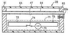
또한, 본 실시 형태에서는 전기 커넥터부(10)에는 통기부(137)가 설치되어 있다. 이 통기부(137)는 내시경(2)의 내부에 삽입 관통한 관로의 외표면과 내시경(2)의 외장 부재(외피부) 사이에서의 수밀식으로 폐색된 영역의 공간부(145)(도34 참조)와, 내시경 외부를 연통하는 연통 구멍이다.In addition, in this embodiment, the
또한, 상기 전기 커넥터부(11)에는 상기 통기부(137)와 마찬가지로, 상기 내시경(2A)의 상기 공간부(145)(도34 참조)와 내시경 외부를 연통하는 통기부(11a)(도34 참조)가 설치되어 있다.In addition, in the
또, 본 실시 형태에서는 상기 커넥터부(10)에 있어서, 내시경(2)의 상기 공간부(145)와 내시경 외부를 연통하는 통기부를 2개 마련한 구성에 대해 설명했지만, 어느 한쪽만의 구성이라도 좋다. 또한, 상기 2개의 통기부(11a, 137)가 어느 한쪽의 통기부는, 누설 테스트용으로서의 연통 구멍으로서 이용되도록 되어 있다.In addition, in this embodiment, although the said
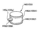
상기 전기 커넥터부(11)에는 누설 테스트용 방수 캡(133)을 착탈 가능하게 접속할 수 있다. 이 방수 캡(133)에는, 후술하지만 누설 테스트용 베이스(133B)와 도시하지 않은 압력 조정 밸브가 설치되어 있다. 또한, 통기부를 2개 마련하여 구성한 경우에는, 상기 커넥터부(10)의 통기부(137)(도34 참조)에도 상기 누설 테스트용 방수 캡(133)과 대략 같은 구성의 누설 테스트용 방수 캡(146)을 착탈 가능하게 접속할 수 있다. 또, 이 누설 테스트용 방수 캡(133)(146)은 전기 커넥터부(11)[또는 커넥터부(10)의 통기부(137)]에 접속한 경우, 이 전기 커넥터부(11)[또는 커넥터부(10)의 통기부(137)]를 수밀하게 유지하는 특성이 있다.The
본 실시 형태의 내시경(2)에서는, 상기 조작부(8)의 대략 중앙 부분에, 증기진입 구멍(138)이 마련되어 있다. 이 증기 진입 구멍(138)은 내시경(2)의 내부에 삽입 관통한 관로의 외표면과 내시경(2)의 외장 부재(외피부) 사이에서의 수밀식으로 폐색된 영역의 공간부(145)(도34 참조)와, 내시경 외부를 연통하는 연통 구멍이다.In the
이 조작부(8)의 증기 진입 구멍(138)에는, 후술하지만 증기 진입 구멍용 방수 캡(147)을 착탈 가능하게 접속할 수 있다.Although mentioned later, the
상기 누설 테스트용 방수 캡(133)(146) 및 증기 진입 구멍용 방수 캡(147)의 구성에 대해서는 후술한다.The configurations of the leakproof
도34는 내시경(2)의 내부에 내장되어 있는 여러 가지 관로를 개략적으로 나타내는 도면이다.FIG. 34 is a diagram schematically showing various pipelines embedded in the
도34에 도시한 바와 같이, 본 실시 형태의 내시경(2)의 커넥터부(10)에는, 상술한 바와 같이 상기 내시경(2)의 내부와 외부를 연통하는 누설 테스트용 구멍으로서의 구멍 혹은 개구로서의 통기부(11a)(137)가 설치되어 있다. 이 통기부(11a)(137)에 의해, 내시경(2)의 외부와, 내시경(2)의 외피부에 의해 밀폐된 내부의 공간부(145)를 연통하도록 하고 있다. 또, 도시하고 있지 않지만 이 통기부(11a)(137)의 일부에, 증기는 통과시키지만 증기보다도 큰 물체는 통과시키지 않는 작은 구멍을 다수 마련한 필터를 마련하도록 해도 좋다.As shown in Fig. 34, in the
또한, 전기 커넥터부(10)에는 상기 내시경(2)의 내부에 내장되어 있는 여러 가지 관로와 연통하는 구멍 혹은 개구로서 공유의 송수 탱크 가압 베이스(23), 기 체 공급 베이스(24), 흡인 베이스(25) 및 주입 베이스(26)가 설치되어 있다. 이들의 개구에 의해, 내시경(2) 내의 각종 관로와 내시경(2)의 외부를 연통하도록 하고 있다.In addition, the
또한, 본 실시 형태에서는 내시경(2)의 조작부의 대략 중앙 근방에는, 상술한 바와 같이 상기 내시경(2)의 내부와 외부를 연통하는 구멍 혹은 개구로서의 증기 진입 구멍(138)이 설치되어 있다. 이 증기 진입 구멍(138)에 의해, 내시경(2)의 외부와 내시경(2)의 외피부에 의해 밀폐된 내부의 공간부(145)를 연통하도록 하고 있다.In addition, in this embodiment, in the substantially center vicinity of the operation part of the
또한, 본 실시 형태에서는 상기 증기 진입 구멍(138)의 일부에 증기는 통과시키지만, 증기보다도 큰 물체, 예컨대 분진이나 내시경 내부의 윤활재 등은 통과시키지 않는 작은 구멍을 다수 마련한 필터(148)를 마련하고 있다. 이 필터(148)는 상기 증기 진입 구멍(138)에 착탈 가능하며 교환이 가능하다. 이 필터(148)는, 예컨대 상기 내시경(2)을 수용한 상기 수납 케이스(34)를 덮으면서 멸균 처리 등을 행하기 위한 멸균용 팩(도시하지 않음)에 이용된 종이 필터와 같은 필터이다. 또, 상기 필터(148)는 멸균용 팩(도시하지 않음)의 종이 필터에 한정되는 것은 아니며, 다른 필터를 이용해도 좋다. 또한, 상기 필터(148)에, 멸균 효과를 확인하기 위한 화학적 인디케이터, 혹은 생물학적 인디케이터를 부착하여, 멸균 처리를 했을 때의 멸균 효과를 확인하도록 구성해도 좋다.In the present embodiment, the
본 실시 형태에서는, 고온 고압 증기로 멸균 처리할 때에 상기 통기부(11a)(137) 및 증기 진입 구멍(138)으로부터 공간부(145) 내로 고온 고압 증기를 유입시켜, 이 공간부(145)에 연통하는 송기 송수용 관로 등의 관로의 외측을 고온 고압 증기로 단시간에 가온할 수 있도록 하고 있다. 즉, 상기 관로의 외측을 따뜻하게 함으로써, 상기 관로 내의 멸균 효과를 촉진시키도록 하고 있다. 또, 상술한 송수 탱크 가압 베이스(23), 기체 공급 베이스(24), 흡인 베이스(25) 및 주입 베이스(26)의 각 개구로부터 내시경(2) 내의 각 관로 내로 고온 고압 증기를 유입시켜, 이들 개구에 연통하는 각 관로의 내측을 고온 고압 증기로 단시간에 가온할 수 있도록 하고 있다. 이렇게 해서, 관로 내외로부터 가온함으로써 내시경에 내장된 관로 내를 빠르게 멸균 처리할 수 있도록 하고 있다.In this embodiment, when sterilizing with high temperature and high pressure steam, the high temperature and high pressure steam is introduced into the
상기 각 관로는, 도34에 도시한 바와 같이 배치되어 있다.Each said pipe line is arrange | positioned as shown in FIG.
관로(139)는 주로 삽입부(7) 내에 있으며, 그 관로 선단부(139a)는 선단부(17)에 있어서 외부에 대하여 개방하고 있고, 관로 후단부(139b)는 조작부(8)에 있어서 외부에 대하여 개방하고 있다. 상기 관로(139)는 예컨대 처치구 삽입 관통용 혹은 흡인용 관로이다.The
관로(141)는 주로 연결 코드(9) 내에 있고, 이 관로 후단부(141d)는 흡인 베이스(25)에 커넥터부(10)에 있어서 외부에 대하여 개방하고 있다. 상기 관로(141)는 예컨대 흡인용 관로이다. 관로(140)는 주로 조작부(8) 내에 있으며, 그 관로 선단부는 관로 선단부(139a)와 공통으로, 선단부(17)에 있어서 외부에 대하여 개방하고 있으며, 관로 후단부는 관로 후단부(141a)와 공통으로, 흡인 베이스(25)에 의해 커넥터부(10)에 있어서 외부에 대하여 개방하고 있다.The
그리고 관로 후단부(141a)[흡인 베이스(25)]에 도시하지 않은 흡인기로부터 의 관로를 접속하여 흡인기로 흡인 조작하여 관로 후단부(139b)를 막아 두면, 관로(141), 관로(140), 관로(139)라는 경로에서 관로 선단부(139a)로부터 흡인을 할 수 있다.And if the pipeline from the aspirator which is not shown in the
관로(142)는 주로 삽입부(7) 내에 있으며, 그 관로 선단부(142a)는 선단부(17)에 있어서 외부에 대하여 개방하고 있으며, 관로 후단부(143a)는 관로(143)와 공통으로 송수 탱크 가압 베이스(23), 기체 공급 베이스(24)에 의해 커넥터부(10)에 있어서 외부에 대하여 개방하고 있다. 상기 관로(142)는 예컨대 선단부(17)의 렌즈면의 세정으로 송기나 송수를 하는 송기 송수용의 관로이다.The
관로(143)는 주로 연결 코드(9) 내에 있으며, 그 관로 선단부(143a)는 관로 선단부(142a)와 공통으로, 선단부(17)에 있어서 외부에 대하여 개방하고 있으며, 관로 후단부(143a)는 송수 탱크 가압 베이스(23), 기체 공급 베이스(24)에 의해 커넥터부(10)에 있어서 외부에 대하여 개방하고 있다. 관로 후단부(143a)[송수 탱크 가압 베이스(23), 기체 공급 베이스(24)]로부터 송기 또는 송수를 행하면, 관로 선단부(142a)로부터 송기 또는 송수할 수 있다.The
관로(144)는 주로 삽입부(7), 조작부(8), 연결 코드(9) 내에 있으며, 그 관로 선단부(144a)는 선단부(17)에 있어서 외부에 대하여 개방하고 있고, 관로 후단부(144b)는 주입 베이스(26)에 의해 커넥터부(10)에 있어서 외부에 대하여 개방하고 있다. 관로(144)는 예컨대 관찰 대상물로 송액하는 전방 송수용의 관로이다.The
이와 같이, 본 실시 형태에 있어서도 내시경(2) 내에는 내측으로 유체 등을 삽입 관통 가능하게 하는 여러 가지 관로가 내장되어 있다. 게다가, 삽입부(7)와 연결 코드(9)는 모두 유연한 부재로 형성되어, 속이 차 있지 않은 비어 있는 상태이다. 또한, 삽입부(7)와 연결 코드(9) 내의 관로의 대부분은, 유연한 움직임에 대응할 수 있도록 중공 부분에 비고정 상태로 배치되어, 관로 주위는 다른 내장물은 있지만, 대부분 공간으로 되어 있다.As described above, also in the present embodiment, the
이들 관로의 단부 이외의 중간 부분에 있어서의 관로의 외측[내시경(2)의 외피 내측]은 주위의 공간부(145)와 연통하여, 이 공간부(145)는 통기부(11a)(137) 및 증기 진입 구멍(138)에 의해 외부와 연통하고 있다. 즉, 관로 외측은 공간부(145)와 연통하는 통기부(11a)(137) 및 증기 진입 구멍(138)을 거쳐서 외부와 연통하는 상태로 되어 있다. 그리고 이 통기부(11a)(137)에 의한 연통 상태는, 상기 누설 테스트용 방수 캡(133)의 장착/미장착(제거)에 의해 선택할 수 있다. 또한, 상기 증기 진입 구멍(138)에 의한 연통 상태는 상기 증기 진입 구멍용 방수 캡(147)의 장착/미장착(제거)에 의해 선택할 수 있다.The outside (inside of the outer shell of the endoscope 2) of the pipeline in the intermediate portions other than the ends of these pipelines communicates with the surrounding
본 실시 형태에서는, 예컨대 어떤 관로의 개구부와 개구부를 연결하는 경로의 중간부 주변에는, 충전제나 고형물에 의해 내시경(2)의 외피 내측을 충전하는 일없이, 상기 공간부(145)가 형성되는 공간이 확보되어 있다. 또한, 그 공간부(145)와 통기부(11a)(137)와의 경로의 도중에도 여러 가지 내장물이나 부품이 존재하지만, 그들은 증기의 길을 차단하지 않도록 배치되어 있다. 따라서 이 경로에 의해 증기는 저해되는 일없이 통과할 수 있다.In this embodiment, the space in which the said
본 실시 형태의 내시경(2)에서는, 통기부(11a)(137) 및 증기 진입 구멍(138)을 마련함으로써, 멸균 처리를 하는 경우에, 내시경(2)의 내부에 마련된 각 관로에 서의 그 주위의 공간부(145)와 연통시킬 수 있어, 예비 진공 시에 공간부(145)도 예비 진공 상태로 설정할 수 있다. 또한, 송수 탱크 가압 베이스(23), 기체 공급 베이스(24), 흡인 베이스(25) 및 주입 베이스(26) 등의 관로 개구를 마련함으로써, 멸균 처리를 하는 경우에 내시경(2)의 내부에 마련된 각 관로와 연통시킬 수 있어, 예비 진공 시에 각 관로 내도 예비 진공 상태로 설정할 수 있다. 또한, 멸균 처리를 하기 전의 누설 테스트(누수 테스트)를 하는 경우에는 상기 통기부(11a)(137)에 누설 테스트용 방수 캡(133)(146), 상기 증기 진입 구멍(38)에 증기 진입 구멍용 방수 캡(147)을 장착함으로써, 누설 테스트나 세정 처리를 하는 경우에 상기 통기부(11a)(137) 및 증기 진입 구멍(138)을 수밀하게 유지할 수 있다.In the
따라서 상기 내시경(2)은, 그 후의 고온 고압 증기 멸균하는 공정에 있어서, 관로의 내측은 물론, 관로의 외측 공간부(145)에도 고온 고압 증기를 빠르게 공급하여 충만 가능하게 하여 고온 고압 증기 멸균 처리를 단시간에 종료할 수 있도록 되어 있다.Therefore, the
다음에, 상기 누설 테스트용 방수 캡(133)(146) 및 증기 진입 구멍용 방수 캡(147)의 구성을 도35를 참조하면서 설명한다.Next, the configurations of the leak test
도35에 도시한 바와 같이, 누설 테스트용 방수 캡(133)(146)은 종래부터 사용되고 있는 것으로, 상기 통기부(11a)(137)를 수밀하게 유지하는 방수 캡 본체(133A)(146A)와, 이 방수 캡 본체(133A)(146A)의 측면에 마련되어, 누설 테스트 시에 도시하지 않은 가압 펌프로부터의 튜브와 접속하기 위한 누설 테스트용 베이스(133B)(146B)를 갖고 있다. 상기 누설 테스트용 베이스(133B)(146B)는 개구 (133a)(146a)를 갖고, 이 개구(133a)(146a)는 내부에 마련된 압력 조정 밸브(도시하지 않음), 상기 방수 캡 본체(133A)(146A) 내를 거쳐서 상기 통기부(11a)(137)에 연통하고 있다.As shown in Fig. 35, the leakproof
상기 누설 테스트용 방수 캡(133)(146)은 상기 내시경(2)의 누설 테스트 시에는 상기 도시하지 않은 가압 펌프로부터의 튜브를 상기 누설 테스트용 베이스(133B)에 접속하고, 상기 가압 펌프로부터의 에러를 이 누설 테스트용 베이스(133B), 방수 캡 본체(133A)를 거쳐서 내시경(2) 내부로 송기한다.The leak test
또한, 상기 누설 테스트용 방수 캡(133)(146)에는 작업자가 상기 증기 진입 구멍용 방수 캡(147)과의 식별을 가능하게 하기 위한 식별 수단(133C)(146C)이 설치되어 있다. 이 식별 수단(133c)(146C)은, 예컨대 녹색 등의 색 부재에 의해 방수 캡 본체(133A)(146A)의 외주 상 전체, 혹은 일부가 도포됨으로써 형성되어 있다.In addition, the leakproof
한편, 새롭게 마련된 증기 진입 구멍용 방수 캡(147)은 도36에 도시한 바와 같이 상기 증기 진입 구멍(138)을 수밀하게 유지하는 방수 캡 본체(147A)와, 이 방수 캡 본체(147A)의 측면에 마련되어, 누설 테스트 시에 상기 필터(148)(도34 참조)의 폐색의 유무를 판단하기 위한 폐색 검지용 역지 밸브(147B)를 갖고 있다.On the other hand, the newly provided
상기 폐색 검지용 역지 밸브(147B)는, 개구(147a)를 갖고, 이 개구(147a)는 내부에 마련된 압력 조정 밸브(도시하지 않음), 상기 방수 캡 본체(147A) 내를 거쳐서 상기 증기 진입 구멍(138)에 연통하고 있다.The closing
또한, 상기 증기 진입 구멍용 방수 캡(147)에는 작업자가 상기 누설 테스트 용 방수 캡(133)(146)과의 식별을 가능하게 하기 위한 식별 수단(147C)이 설치되어 있다. 이 식별 수단(147C)은, 예컨대 적색 등의 색 부재에 의해 방수 캡 본체(147A)의 외주 상 전체, 혹은 일부가 도포됨으로써 형성되어 있다.In addition, the
따라서 작업자는 상기 식별 수단(133C)(146C)(147C)에 의해, 상기 누설 테스트용 방수 캡(133)(146)과 상기 증기 진입 구멍용 방수 캡(147)을 한눈에 인식하는 것이 가능해진다.Accordingly, the operator can recognize the leakproof
또, 본 실시 형태에서는 상기 식별 수단은 녹색이나 적색 등의 색 부재에 한정되는 것은 아니며, 예컨대 작업자가 한눈에 그들 종별을 식별할 수 있는 것이면 어떠한 방법을 이용해도 좋다.In addition, in this embodiment, the said identification means is not limited to color members, such as green and red, and what kind of method may be used, for example, as long as an operator can identify those types at a glance.
또한, 상기 증기 진입 구멍용 방수 캡(147)의 폐색 검지용 역지 밸브(147B)는, 도36에 도시한 바와 같이 방수 캡 본체(147A)의 표면에 마련하여 구성해도 좋다. 이 경우, 방수 캡 본체(147A)의 표면에 폐색 검지용 역지 밸브(147b)를 마련하는 동시에, 상기 폐색 검지용 역지 밸브(147B)를, 상기 증기 진입 구멍(138)과 연통하여 필터의 폐색 검지를 위한 가압용 베이스로서 구성해도 좋다.The blocking
다음에, 본 실시 형태의 내시경 시스템의 작용에 대해 도33 내지 도36을 참조하면서 설명한다.Next, the operation of the endoscope system of the present embodiment will be described with reference to FIGS. 33 to 36.
현재, 본 실시 형태의 내시경(2)의 검사 후에, 세정을 하는 것으로 한다.It is assumed that washing is performed after the inspection of the
이 경우, 상기 리스크 테스트용 방수 캡(133)(146)을 상기 통기부(11a)(137)에 장착하는 동시에, 상기 증기 진입 구멍용 방수 캡(147)을 상기 증기 진입 구멍(138)에 장착하고, 또한 도시하지 않은 가압 펌프의 튜브를 상기 누설 테스트용 베 이스(133B)(146B)에 접속하여, 검사 후의 내시경(2)을 세정 장치에 수용한다.In this case, the
본 실시 형태에서는, 상기 누설 테스트용 방수 캡(133)(146) 및 증기 진입 구멍용 방수 캡(147)을 장착하고 있으므로, 세정 중인 세정액 등이 내시경 내부로 진입하지 않는다. 또한, 상기 증기 진입 구멍용 방수 캡(147)은, 매우 눈에 띄는 적색 등의 색 부재로 형성한 식별 수단(147C)을 마련하고 있으므로, 작업자가 이 장착 작업을 잊는 것을 방지할 수 있다.In this embodiment, since the said
그리고 작업자는, 그 상태에서 내시경(2)의 누설 테스트를 한다. 이 경우, 작업자는 종래와 동일한 순서로 누설 테스트를 실시할 수 있으므로, 위화감 없이 누설 테스트를 할 수 있다.And the operator performs the leakage test of the
여기서, 본 실시 형태에서는 누설 테스트에 필요한 압력을 P1, 누설 테스트장치(도시하지 않았지만 가압 펌프 등)의 최대 설정 압력을 P2, 상기 폐색 검지용 역지 밸브(147B)의 개방 압력을 P3이라 하면, 본 실시 형태의 내시경 시스템은 P1 < P3 < P2가 되는 관계를 만족하도록 상기 각종 부위가 설정되어 있다.Here, in this embodiment, when the pressure required for a leak test is P1, the maximum set pressure of a leak test apparatus (not shown but a pressure pump etc.) is P2, and the opening pressure of the said block
따라서 작업자는 최초로, 누설 테스트 장치(도시하지 않음)의 설정 압력을 상기 압력 P1로 행하여, 누수가 없는 것을 확인하였다면, 그대로 설정 압력을 상기 압력 P3 이상으로 바꾼다. 이 경우, 필터(148)가 막혀 있지 않으면 상기 폐색 검지용 역지 밸브(147B)가 이 시점에서 개방되므로, 이 폐색 역지 밸브(147B)의 개구(147a)로부터 공기가 나오게 된다.Therefore, when an operator first performs the set pressure of a leak test apparatus (not shown) by the said pressure P1, and confirms that there is no leak, it changes a set pressure as it is above the said pressure P3 or more. In this case, if the
한편, 상기 필터(148)가 막혀 있으면, 상기 증기 진입 구멍용 방수 캡(147)으로 충분한 공기가 이송되지 않으므로, 이 폐색 검지용 역지 밸브(147B)가 개방되 지 않아, 공기는 송출되지 않는다.On the other hand, if the
이상과 같이, 작업자에게 있어서 종래의 작업과 대략 동일한 작업으로, 누설 테스트와 필터(148)의 폐색을 확인할 수 있다.As described above, the leakage test and the blockage of the
누설 테스트 후, 작업자는 상기 내시경(2)에 상기 누설 테스트용 방수 캡(133)(146) 및 증기 진입 구멍 방수 캡(147)을 장착한 채로, 이 내시경(2)을 세정 장치에 의해 세정을 한다. 이 경우, 작업자는 종래의 세정 처리와 마찬가지로 행하므로, 위화감 없이 세정 처리를 할 수 있다.After the leak test, the operator cleans the
세정 처리 후, 작업자는 상기 증기 진입 구멍(138)으로부터 상기 증기 진입 구멍용 방수 캡(147)을 제거한 후, 고온 고압 증기 멸균 장치에 투입한다. 이 경우, 상기 누설 테스트용 방수 캡(133)(146)은 고온 고압 증기 멸균에 대하여 내성이 있는 것이면, 제거해도 제거하지 않아도 좋다. 또, 종래의 누설 테스트용 방수 캡은 고온 고압 증기 멸균에 대하여 내성이 없는 경우가 많기 때문에, 제거하여 고온 고압 증기 멸균 처리를 하는 쪽이 바람직하다. 또한, 본 실시 형태에서는 상기 누설 테스트용 방수 캡(133)(146) 및 상기 증기 진입 구멍용 방수 캡(147)은 작업자가 식별하기 쉽도록 예컨대 색에 따라 식별 가능하게 하는 식별 수단(133C)(146C)(147C)을 갖고 있으므로, 또한 각 방수 캡의 배치 위치도 다르기 때문에, 작업자가 방수 캡을 착각하는 것을 방지할 수 있다.After the cleaning process, the worker removes the
고온 고압 증기 멸균 처리 중, 상기 내시경(2)은 상기 증기 진입 구멍(138)으로부터[상기 누설 테스트용 방수 캡(133)(146)을 제거한 경우에는 상기 통기부(11a)(137)로부터도] 증기가 내시경 내부[공간부(145)]로 침투하게 된다. 이로 인 해, 이 내시경(2) 내부에 삽입 관통되는 각종 관로(139 내지 144)의 외표면 등을 빨리 따뜻하게 하는 것이 가능해지므로, 각 관로 내의 멸균 처리도 종래보다 빠르게 행할 수 있다. 또, 상기 증기 진입 구멍(138)은 조작부(8)의 중앙 근방에 설치되어 있으므로, 내시경 내부[공간부(145)]로 증기가 침투하기 쉬워지고, 또한 관로의 개구부와 개구부를 연결하는 경로 한가운데의 부분 주변에 대해서도, 그 외표면이 빨리 따뜻해지게 되므로, 종래 시간이 필요한 관로의 중앙 부분에 대해서도 빠르게, 멸균 처리를 할 수 있다.During the high temperature and high pressure steam sterilization process, the
또한, 본 실시 형태에서는 상기 증기 진입 구멍(138)의 일부에 필터(148)가 설치되어 있으므로, 고온 고압 증기 멸균 처리 중에 내시경 내부로부터 윤활제 등이 유출되는 일도 없고, 반대로 내시경 외부로부터 분진 등이 진입하는 일도 없다.In addition, in this embodiment, since the
또, 본 실시 형태에서는 상기 누설 테스트용 구멍인 통기부(11a)는, 종래 이용된 누설 테스트용 구멍이므로, 그 지름이 예컨대 ø 1 ㎜와 같이 매우 작지만, 상기 증기 진입 구멍(138)은 상기 통기부(11a)와는 별도로 마련한 것이므로, 충분히 증기가 진입하는 만큼의 크기, 예컨대 그 지름이 ø 9 ㎜가 되도록 설계하면 좋다.In addition, in this embodiment, since the ventilation part 11a which is the said leak test hole is a leak test hole used conventionally, the diameter is very small like ø1mm, for example, but the said
또한, 본 실시 형태에서는 상기 통기부(11a)를 누설 테스트용 구멍으로서 마련한 경우에, 상기 통기부(137)는 누설 테스트용 구멍이 아닌 증기 진입 구멍으로서 이용하도록 구성해도 좋다. 또, 상기 증기 진입 구멍(138)을 조작부(8)에 한정되지 않으며, 필요에 따라서 그 밖의 위치에 또한 복수 마련하여 구성해도 좋다.In addition, in this embodiment, when the said ventilation part 11a is provided as a leak test hole, the said
또한, 상기 누설 테스트용 구멍으로서의 상기 통기부(11a)를 갖는 상기 전기 커넥터부(11) 주변은 종래 구성과 대략 같으므로, 이 전기 커넥터부(11)에 접속되는 시스템, 예컨대 누설 테스트용 방수 캡(133) 등은 종래의 것과 호환성이 있으므로, 새롭게 부재를 마련할 필요도 없으므로, 비용의 저감화에도 공헌할 수 있다.In addition, since the periphery of the
따라서 본 실시 형태에 따르면, 누설 테스트용의 연통 구멍 외에 내시경 내부와 연통하는 것 외의 증기 진입 구멍을 마련한 구성으로 함으로써 내시경에 내장된 관로 내의 멸균을 종래보다 빠르게 하는 것이 가능해진다.Therefore, according to this embodiment, the sterilization in the pipe | tube embedded in an endoscope can be made faster than before by setting it as the structure which provided the vapor entrance hole other than communicating with the inside of an endoscope in addition to the communication hole for a leak test.
이상과 같이, 본 실시 형태의 내시경 장치는 누설 테스트용의 연통 구멍 외에 내시경 내부와 연통하는 것 외의 증기 진입 구멍을 마련한 구성으로 함으로써 내시경에 내장된 관로 내의 멸균을 종래보다 빠르게 할 수 있는 등의 이점이 있다.As described above, the endoscope apparatus according to the present embodiment has a configuration in which a vapor entry hole other than communicating with the inside of the endoscope is provided in addition to the communication hole for the leak test, so that sterilization in the pipeline embedded in the endoscope can be performed faster than before. There is this.
또, 본 발명은 이상 서술한 복수의 실시 형태에만 한정되는 것은 아니며, 발명의 요지를 일탈하지 않는 범위에서 여러 가지 변형 실시 가능하다.In addition, this invention is not limited only to the some embodiment mentioned above, A various deformation | transformation is possible in the range which does not deviate from the summary of invention.
본 발명의 내시경 장치는 내시경 내부와 연통하는 것 외의 증기 진입 구멍을 마련한 구성으로 함으로써 내시경에 내장된 관로 내의 멸균을 종래보다 빠르게 할 수 있으므로, 내시경에 의한 내시경 검사가 복수예 행해져, 최초의 검사에서 사용한 내시경을 리프로세스하여 같은 날에 몇 번이나 사용하는 경우에는 특히 유효하다.The endoscope device according to the present invention can be sterilized in a conduit embedded in the endoscope faster than conventionally by providing a vapor inlet hole other than communicating with the inside of the endoscope. This is especially effective when the endoscope is used to reprocess and use it several times a day.
Claims (22)
Translated fromKoreanApplications Claiming Priority (6)
| Application Number | Priority Date | Filing Date | Title |
|---|---|---|---|
| JP2003200154AJP4472280B2 (en) | 2003-07-22 | 2003-07-22 | Endoscope high-temperature high-pressure steam sterilization treatment method |
| JPJP-P-2003-00200154 | 2003-07-22 | ||
| JPJP-P-2003-00286093 | 2003-08-04 | ||
| JP2003286093AJP4472290B2 (en) | 2003-08-04 | 2003-08-04 | Endoscope high-temperature high-pressure steam sterilization treatment method |
| JPJP-P-2003-00425833 | 2003-12-22 | ||
| JP2003425833AJP4520141B2 (en) | 2003-12-22 | 2003-12-22 | Endoscope device |
Publications (2)
| Publication Number | Publication Date |
|---|---|
| KR20060038454A KR20060038454A (en) | 2006-05-03 |
| KR100845079B1true KR100845079B1 (en) | 2008-07-09 |
Family
ID=34084264
Family Applications (1)
| Application Number | Title | Priority Date | Filing Date |
|---|---|---|---|
| KR1020067001315AExpired - Fee RelatedKR100845079B1 (en) | 2003-07-22 | 2004-07-22 | High temperature and high pressure steam sterilization method for endoscope, and endoscope |
Country Status (7)
| Country | Link |
|---|---|
| US (1) | US7399273B2 (en) |
| EP (1) | EP1645293B1 (en) |
| KR (1) | KR100845079B1 (en) |
| AU (1) | AU2004257531B2 (en) |
| CA (1) | CA2532652C (en) |
| DE (1) | DE602004032442D1 (en) |
| WO (1) | WO2005007205A1 (en) |
Families Citing this family (20)
| Publication number | Priority date | Publication date | Assignee | Title |
|---|---|---|---|---|
| DE102006031444A1 (en)* | 2006-07-07 | 2008-01-17 | Zf Friedrichshafen Ag | transmission system |
| JP4904470B2 (en)* | 2007-09-19 | 2012-03-28 | 富士フイルム株式会社 | Observation image forming apparatus |
| EP2303100B1 (en)* | 2008-04-16 | 2020-02-12 | United States Endoscopy Group, Inc. | Adaptor for a water bottle of an endoscope |
| WO2010028059A1 (en)* | 2008-09-02 | 2010-03-11 | Medtronic Ablation Frontiers Llc | Irrigated ablation catheter system and methods |
| DE102009011479A1 (en)* | 2009-03-06 | 2010-09-09 | Olympus Winter & Ibe Gmbh | Surgical instrument |
| USD639940S1 (en)* | 2009-04-15 | 2011-06-14 | Bracco Diagnostics Inc. | Gas water bottle adaptor |
| MX2011012003A (en) | 2009-05-13 | 2012-01-27 | Lantheus Medical Imaging Inc | Radionuclide generator and method of sterilization. |
| CN102686142B (en) | 2009-08-31 | 2014-10-29 | 布拉蔻诊断公司 | In-line gas adapter for endoscopic apparatus |
| WO2011032067A1 (en) | 2009-09-14 | 2011-03-17 | Bracco Diagnostics Inc. | In-line gas adaptor for endoscopic apparatus |
| KR101103758B1 (en)* | 2010-12-30 | 2012-01-12 | 이상일 | Endoscope sterilization device and sterilization method |
| US10245042B2 (en)* | 2012-03-13 | 2019-04-02 | Medtronic Xomed, Inc. | Check valve vented sterilizable powered surgical handpiece |
| EP2830477A1 (en) | 2012-03-30 | 2015-02-04 | Bracco Diagnostics Inc. | Water bottle cap assemblies for an endoscopic device |
| JP5941753B2 (en)* | 2012-05-28 | 2016-06-29 | 富士フイルム株式会社 | Electronic endoscope apparatus, imaging module, and imaging lens molding method |
| US10350318B2 (en)* | 2015-05-15 | 2019-07-16 | Virender K. Sharma | Method and system for steam sterilization of endoscopes |
| CN106039334B (en)* | 2016-06-30 | 2019-03-01 | 张家港华菱医疗设备股份公司 | Inoculated needle sterilizer and its sterilizing methods |
| WO2018024690A1 (en)* | 2016-08-01 | 2018-02-08 | Cantel Medical (Uk) Limited | Universal endoscope drying cabinet |
| KR101856548B1 (en)* | 2017-08-23 | 2018-05-11 | 링크플로우 주식회사 | Method for street view service and apparatus for using the method |
| EP3662810A4 (en)* | 2017-08-31 | 2020-07-08 | Sony Corporation | DEVICE FOR PROCESSING MEDICAL IMAGES, SYSTEM FOR PROCESSING MEDICAL IMAGES AND CONTROL METHOD OF A DEVICE FOR PROCESSING MEDICAL IMAGES |
| US10188483B1 (en) | 2018-08-03 | 2019-01-29 | Phong Duy Bui | Gastro-intestinal scope sterilization, disinfection and storage device and methods of making and using same |
| US10525156B1 (en) | 2018-08-03 | 2020-01-07 | Phong Duy Bui | Method of using a gastro-intestinal scope for the disinfection of a colon |
Citations (1)
| Publication number | Priority date | Publication date | Assignee | Title |
|---|---|---|---|---|
| JP2000051323A (en)* | 1998-08-07 | 2000-02-22 | Olympus Optical Co Ltd | Autoclave sterilization method |
Family Cites Families (11)
| Publication number | Priority date | Publication date | Assignee | Title |
|---|---|---|---|---|
| US5288467A (en)* | 1988-06-06 | 1994-02-22 | Hans Biermaier | Cleaning and disinfecting machine for medical equipment and instruments, anesthetic tubes, catheters, and endoscopes |
| JP3159464B2 (en) | 1991-04-12 | 2001-04-23 | オリンパス光学工業株式会社 | Endoscope |
| US5156590A (en)* | 1991-06-24 | 1992-10-20 | Wolfgang Vilmar | Uretero-renoscope with catheter body having plural partitioned inner conduits |
| JP3193444B2 (en)* | 1992-04-28 | 2001-07-30 | 旭光学工業株式会社 | Endoscope internal and external communication device |
| US5634880A (en)* | 1995-05-22 | 1997-06-03 | Johnson & Johnson Medical, Inc. | Endoscope pressure equalization system and method |
| US5868667A (en)* | 1998-03-27 | 1999-02-09 | Ethicon, Inc. | Pressure-equalizing cap |
| JP2001190642A (en)* | 2000-01-14 | 2001-07-17 | Chiyoda Manufacturing Co Ltd | Steam sterilizing device |
| JP3790920B2 (en) | 2000-06-30 | 2006-06-28 | オリンパス株式会社 | High temperature high pressure steam sterilization container |
| JP3833879B2 (en) | 2000-08-04 | 2006-10-18 | オリンパス株式会社 | Endoscope device |
| JP2002065577A (en) | 2000-08-28 | 2002-03-05 | Olympus Optical Co Ltd | Endoscope |
| JP4694054B2 (en) | 2001-07-04 | 2011-06-01 | Hoya株式会社 | Autoclave equipment |
- 2004
- 2004-07-22KRKR1020067001315Apatent/KR100845079B1/ennot_activeExpired - Fee Related
- 2004-07-22EPEP04748037Apatent/EP1645293B1/ennot_activeExpired - Lifetime
- 2004-07-22WOPCT/JP2004/010772patent/WO2005007205A1/enactiveApplication Filing
- 2004-07-22AUAU2004257531Apatent/AU2004257531B2/ennot_activeCeased
- 2004-07-22DEDE602004032442Tpatent/DE602004032442D1/ennot_activeExpired - Lifetime
- 2004-07-22CACA002532652Apatent/CA2532652C/ennot_activeExpired - Fee Related
- 2004-07-22USUS10/896,791patent/US7399273B2/ennot_activeExpired - Fee Related
Patent Citations (1)
| Publication number | Priority date | Publication date | Assignee | Title |
|---|---|---|---|---|
| JP2000051323A (en)* | 1998-08-07 | 2000-02-22 | Olympus Optical Co Ltd | Autoclave sterilization method |
Also Published As
| Publication number | Publication date |
|---|---|
| CA2532652A1 (en) | 2005-01-27 |
| US7399273B2 (en) | 2008-07-15 |
| DE602004032442D1 (en) | 2011-06-09 |
| EP1645293B1 (en) | 2011-04-27 |
| EP1645293A4 (en) | 2008-04-09 |
| US20050065402A1 (en) | 2005-03-24 |
| EP1645293A1 (en) | 2006-04-12 |
| KR20060038454A (en) | 2006-05-03 |
| AU2004257531A1 (en) | 2005-01-27 |
| CA2532652C (en) | 2008-04-29 |
| AU2004257531B2 (en) | 2007-11-08 |
| WO2005007205A1 (en) | 2005-01-27 |
Similar Documents
| Publication | Publication Date | Title |
|---|---|---|
| KR100845079B1 (en) | High temperature and high pressure steam sterilization method for endoscope, and endoscope | |
| JP4414734B2 (en) | Endoscope system | |
| JP3854045B2 (en) | Endoscope | |
| JP2002253477A (en) | High temperature and high pressure vapor sterilizing vessel for endoscope and system for washing and sterilizing endoscope | |
| KR102025220B1 (en) | Endoscope for arthroscopy | |
| US7850603B2 (en) | Endoscope for sterilizing built-in elongated channel with high-temperature and high-pressure vapor | |
| JP4422501B2 (en) | Endoscope and endoscope system | |
| JPH05337081A (en) | Endoscope sterilizing case | |
| KR102025221B1 (en) | Endoscope for arthroscopy | |
| JP4472280B2 (en) | Endoscope high-temperature high-pressure steam sterilization treatment method | |
| JP4472290B2 (en) | Endoscope high-temperature high-pressure steam sterilization treatment method | |
| JP4520141B2 (en) | Endoscope device | |
| EP1574223A2 (en) | Autoclave sterilization treatment method and autoclave sterilization apparatus using this treatment method | |
| JP4074190B2 (en) | Endoscope device | |
| JP2004105747A (en) | Endoscope system | |
| KR100822543B1 (en) | Endoscopes, Endoscope Systems and Filter Units | |
| JP5000081B2 (en) | Endoscope | |
| JPH08238213A (en) | Fluid controller for endoscope | |
| JP2009000357A (en) | Adapter for cleaning endoscope |
Legal Events
| Date | Code | Title | Description |
|---|---|---|---|
| PA0105 | International application | St.27 status event code:A-0-1-A10-A15-nap-PA0105 | |
| A201 | Request for examination | ||
| P11-X000 | Amendment of application requested | St.27 status event code:A-2-2-P10-P11-nap-X000 | |
| P13-X000 | Application amended | St.27 status event code:A-2-2-P10-P13-nap-X000 | |
| PA0201 | Request for examination | St.27 status event code:A-1-2-D10-D11-exm-PA0201 | |
| PG1501 | Laying open of application | St.27 status event code:A-1-1-Q10-Q12-nap-PG1501 | |
| E902 | Notification of reason for refusal | ||
| PE0902 | Notice of grounds for rejection | St.27 status event code:A-1-2-D10-D21-exm-PE0902 | |
| T11-X000 | Administrative time limit extension requested | St.27 status event code:U-3-3-T10-T11-oth-X000 | |
| E13-X000 | Pre-grant limitation requested | St.27 status event code:A-2-3-E10-E13-lim-X000 | |
| P11-X000 | Amendment of application requested | St.27 status event code:A-2-2-P10-P11-nap-X000 | |
| P13-X000 | Application amended | St.27 status event code:A-2-2-P10-P13-nap-X000 | |
| E902 | Notification of reason for refusal | ||
| PE0902 | Notice of grounds for rejection | St.27 status event code:A-1-2-D10-D21-exm-PE0902 | |
| T11-X000 | Administrative time limit extension requested | St.27 status event code:U-3-3-T10-T11-oth-X000 | |
| T11-X000 | Administrative time limit extension requested | St.27 status event code:U-3-3-T10-T11-oth-X000 | |
| P11-X000 | Amendment of application requested | St.27 status event code:A-2-2-P10-P11-nap-X000 | |
| P13-X000 | Application amended | St.27 status event code:A-2-2-P10-P13-nap-X000 | |
| R17-X000 | Change to representative recorded | St.27 status event code:A-3-3-R10-R17-oth-X000 | |
| R17-X000 | Change to representative recorded | St.27 status event code:A-3-3-R10-R17-oth-X000 | |
| E701 | Decision to grant or registration of patent right | ||
| PE0701 | Decision of registration | St.27 status event code:A-1-2-D10-D22-exm-PE0701 | |
| GRNT | Written decision to grant | ||
| PR0701 | Registration of establishment | St.27 status event code:A-2-4-F10-F11-exm-PR0701 | |
| PR1002 | Payment of registration fee | St.27 status event code:A-2-2-U10-U12-oth-PR1002 Fee payment year number:1 | |
| PG1601 | Publication of registration | St.27 status event code:A-4-4-Q10-Q13-nap-PG1601 | |
| PR1001 | Payment of annual fee | St.27 status event code:A-4-4-U10-U11-oth-PR1001 Fee payment year number:4 | |
| PR1001 | Payment of annual fee | St.27 status event code:A-4-4-U10-U11-oth-PR1001 Fee payment year number:5 | |
| FPAY | Annual fee payment | Payment date:20130621 Year of fee payment:6 | |
| PR1001 | Payment of annual fee | St.27 status event code:A-4-4-U10-U11-oth-PR1001 Fee payment year number:6 | |
| FPAY | Annual fee payment | Payment date:20140626 Year of fee payment:7 | |
| PR1001 | Payment of annual fee | St.27 status event code:A-4-4-U10-U11-oth-PR1001 Fee payment year number:7 | |
| LAPS | Lapse due to unpaid annual fee | ||
| PC1903 | Unpaid annual fee | St.27 status event code:A-4-4-U10-U13-oth-PC1903 Not in force date:20150703 Payment event data comment text:Termination Category : DEFAULT_OF_REGISTRATION_FEE | |
| R18-X000 | Changes to party contact information recorded | St.27 status event code:A-5-5-R10-R18-oth-X000 | |
| PC1903 | Unpaid annual fee | St.27 status event code:N-4-6-H10-H13-oth-PC1903 Ip right cessation event data comment text:Termination Category : DEFAULT_OF_REGISTRATION_FEE Not in force date:20150703 |