KR100844401B1 - Uninterruptible Power Supply with Solar Power Generator - Google Patents
Uninterruptible Power Supply with Solar Power GeneratorDownload PDFInfo
- Publication number
- KR100844401B1 KR100844401B1KR1020060118437AKR20060118437AKR100844401B1KR 100844401 B1KR100844401 B1KR 100844401B1KR 1020060118437 AKR1020060118437 AKR 1020060118437AKR 20060118437 AKR20060118437 AKR 20060118437AKR 100844401 B1KR100844401 B1KR 100844401B1
- Authority
- KR
- South Korea
- Prior art keywords
- leg
- power
- voltage
- load
- battery
- Prior art date
- Legal status (The legal status is an assumption and is not a legal conclusion. Google has not performed a legal analysis and makes no representation as to the accuracy of the status listed.)
- Active
Links
- 238000010248power generationMethods0.000claimsabstractdescription49
- 238000007600chargingMethods0.000claimsabstractdescription23
- 238000007599dischargingMethods0.000claimsabstractdescription15
- 239000003990capacitorSubstances0.000claimsdescription9
- 230000001788irregularEffects0.000claimsdescription4
- 238000000034methodMethods0.000claimsdescription4
- 238000010586diagramMethods0.000description8
- 238000011161developmentMethods0.000description2
- 238000006243chemical reactionMethods0.000description1
- 238000004891communicationMethods0.000description1
- 238000012937correctionMethods0.000description1
- 230000007613environmental effectEffects0.000description1
- 238000003912environmental pollutionMethods0.000description1
- 238000009499grossingMethods0.000description1
- 238000012423maintenanceMethods0.000description1
- 238000012986modificationMethods0.000description1
- 230000004048modificationEffects0.000description1
- 230000000630rising effectEffects0.000description1
Images


Classifications
- H—ELECTRICITY
- H02—GENERATION; CONVERSION OR DISTRIBUTION OF ELECTRIC POWER
- H02J—CIRCUIT ARRANGEMENTS OR SYSTEMS FOR SUPPLYING OR DISTRIBUTING ELECTRIC POWER; SYSTEMS FOR STORING ELECTRIC ENERGY
- H02J9/00—Circuit arrangements for emergency or stand-by power supply, e.g. for emergency lighting
- H02J9/04—Circuit arrangements for emergency or stand-by power supply, e.g. for emergency lighting in which the distribution system is disconnected from the normal source and connected to a standby source
- H02J9/06—Circuit arrangements for emergency or stand-by power supply, e.g. for emergency lighting in which the distribution system is disconnected from the normal source and connected to a standby source with automatic change-over, e.g. UPS systems
- H02J9/062—Circuit arrangements for emergency or stand-by power supply, e.g. for emergency lighting in which the distribution system is disconnected from the normal source and connected to a standby source with automatic change-over, e.g. UPS systems for AC powered loads
- H—ELECTRICITY
- H02—GENERATION; CONVERSION OR DISTRIBUTION OF ELECTRIC POWER
- H02J—CIRCUIT ARRANGEMENTS OR SYSTEMS FOR SUPPLYING OR DISTRIBUTING ELECTRIC POWER; SYSTEMS FOR STORING ELECTRIC ENERGY
- H02J3/00—Circuit arrangements for AC mains or AC distribution networks
- H02J3/04—Circuit arrangements for AC mains or AC distribution networks for connecting networks of the same frequency but supplied from different sources
- H02J3/06—Controlling transfer of power between connected networks; Controlling sharing of load between connected networks
- H—ELECTRICITY
- H02—GENERATION; CONVERSION OR DISTRIBUTION OF ELECTRIC POWER
- H02J—CIRCUIT ARRANGEMENTS OR SYSTEMS FOR SUPPLYING OR DISTRIBUTING ELECTRIC POWER; SYSTEMS FOR STORING ELECTRIC ENERGY
- H02J7/00—Circuit arrangements for charging or depolarising batteries or for supplying loads from batteries
- H02J7/34—Parallel operation in networks using both storage and other DC sources, e.g. providing buffering
- H02J7/35—Parallel operation in networks using both storage and other DC sources, e.g. providing buffering with light sensitive cells
- Y—GENERAL TAGGING OF NEW TECHNOLOGICAL DEVELOPMENTS; GENERAL TAGGING OF CROSS-SECTIONAL TECHNOLOGIES SPANNING OVER SEVERAL SECTIONS OF THE IPC; TECHNICAL SUBJECTS COVERED BY FORMER USPC CROSS-REFERENCE ART COLLECTIONS [XRACs] AND DIGESTS
- Y02—TECHNOLOGIES OR APPLICATIONS FOR MITIGATION OR ADAPTATION AGAINST CLIMATE CHANGE
- Y02B—CLIMATE CHANGE MITIGATION TECHNOLOGIES RELATED TO BUILDINGS, e.g. HOUSING, HOUSE APPLIANCES OR RELATED END-USER APPLICATIONS
- Y02B10/00—Integration of renewable energy sources in buildings
- Y02B10/70—Hybrid systems, e.g. uninterruptible or back-up power supplies integrating renewable energies
- Y—GENERAL TAGGING OF NEW TECHNOLOGICAL DEVELOPMENTS; GENERAL TAGGING OF CROSS-SECTIONAL TECHNOLOGIES SPANNING OVER SEVERAL SECTIONS OF THE IPC; TECHNICAL SUBJECTS COVERED BY FORMER USPC CROSS-REFERENCE ART COLLECTIONS [XRACs] AND DIGESTS
- Y10—TECHNICAL SUBJECTS COVERED BY FORMER USPC
- Y10S—TECHNICAL SUBJECTS COVERED BY FORMER USPC CROSS-REFERENCE ART COLLECTIONS [XRACs] AND DIGESTS
- Y10S323/00—Electricity: power supply or regulation systems
- Y10S323/906—Solar cell systems
Landscapes
- Engineering & Computer Science (AREA)
- Power Engineering (AREA)
- Business, Economics & Management (AREA)
- Emergency Management (AREA)
- Stand-By Power Supply Arrangements (AREA)
- Charge And Discharge Circuits For Batteries Or The Like (AREA)
Abstract
Translated fromKoreanDescription
Translated fromKorean도 1은 종래의 실시예에 따른 정류기-인버터형 무정전 전원투입장치를 나타내는 회로도,1 is a circuit diagram showing a rectifier-inverter type uninterruptible power supply device according to a conventional embodiment;
도 2는 본 발명의 일실시예에 따른 태양광 발전장치가 구비된 무정전 전원투입장치를 나타내는 회로도,2 is a circuit diagram showing an uninterruptible power supply device with a photovoltaic device according to an embodiment of the present invention;
도 3a, 3b, 3c는 본 발명의 일실시예에 따른 태양광 발전장치가 구비된 무정전 전원투입장치를 이용한 정전시 동작상태를 나타내는 전류흐름도,3A, 3B, and 3C are current flow diagrams illustrating an operation state during power failure using an uninterruptible power supply device with a solar power generator according to an embodiment of the present invention;
도 4a, 4b, 4c는 본 발명의 일실시예에 따른 태양광 발전장치가 구비된 무정전 전원투입장치를 이용한 계통 연결시 태양광 발전 및 배터리 충전상태를 나타내는 전류흐름도이다.4A, 4B, and 4C are diagrams illustrating current flows showing solar power generation and battery charging states when grids are connected using an uninterruptible power supply device having a photovoltaic device according to an embodiment of the present invention.
*도면의 주요부분에 대한 부호의 설명** Description of the symbols for the main parts of the drawings *
4:교류입력, 12:직류전력저장콘덴서,4: AC input, 12: DC power storage capacitor,
18:교류출력, 20:부하,18: AC output, 20: Load,
32:정류기leg, 34:태양전지,32: rectifier leg, 34: solar cell,
36:발전leg, 38:배터리,36: power generation leg, 38: battery,
40:충방전leg, 42:공통leg,40: charge and discharge leg, 42: common leg,
44:인버터leg.44: inverter leg.
본 발명은 태양광 발전장치가 구비된 무정전 전원투입장치에 관한 것으로, 보다 상세하게 태양광 발전장치를 계통연계하고, 입력 및 출력변압기를 제거하고, 발전 및 충방전 leg을 구비함으로써 변압기를 통한 전력손실 및 도통손실을 방지하도록 함으로써 고효율 전력의 제공이 가능하도록 한 태양광 발전장치가 구비된 무정전 전원투입장치에 관한 것이다.The present invention relates to an uninterruptible power supply device equipped with a solar power generation device, and more specifically, to grid-connected the solar power generation device, to remove the input and output transformer, and to provide a power generation and charging and discharging leg to power through the transformer The present invention relates to an uninterruptible power supply device having a photovoltaic device capable of providing high efficiency power by preventing loss and conduction loss.
주지된 바와 같이, 일반적으로 통신시스템, 의료시스템 등 중요 시스템에서는 전원 투입이 정지된 경우, 즉 정전된 경우 유저에게 엄청난 부가가치의 손실을 발생시키며, 의료시스템을 이용한 수술도중 정전이 발생되면 환자의 생명에 심각한 위협을 초래하게 되므로 이러한 주요 시스템에는 무정전 시스템이 구축되어져 있다.As is well known, in general, important systems such as communication systems and medical systems cause a huge loss of added value to users when the power supply is stopped, i.e., when the power is interrupted, and when a power failure occurs during the operation using the medical system, the patient's life is lost. These major systems are equipped with an uninterruptible system because they pose a serious threat.
이러한 무정전 시스템에는 일반적으로 on-line 무정전전원장치가 많이 사용되고 있는 바, 상기 On-line 무정전전원장치에서는 점차 강화되고 있는 입력전원의 환경 규제에 따라 고역률과 국가적인 차원에서의 고효율이 요구되고 있다. 또한 시장 상황에 따라 시스템의 크기 및 무게 감소와 저가격화가 요구되고 있다.On-line uninterruptible power supplies are generally used in such an uninterruptible system, and the on-line uninterruptible power supplies require high power factor and high efficiency at a national level in accordance with environmental regulations of input power which is gradually strengthened. . In addition, depending on market conditions, the size and weight of the system are reduced and the price is lowered.
이와 달리 최근 고유가 시대 에너지 수급 불안 해소를 위한 대체에너지 개발이 활발히 이루어지고 있으며, 특히 환경오염을 방지하기 위한 친환경적 에너지로 태양광발전 시스템의 개발이 활발히 진행되고 있다.On the other hand, the development of alternative energy to solve the energy supply and demand instability in the high oil price era has been actively carried out. In particular, the development of a photovoltaic power generation system is being actively conducted as an eco-friendly energy to prevent environmental pollution.
종래의 방식으로 태양광발전 시스템을 무정전전원장치에 이용할 경우, 태양광발전전력을 계통으로 연계한 후 이를 다시 직류전력으로 변환한 후 인버터를 통하여 교류전력을 부하에 공급해야 한다. 이와 같은 경우, 여러 번의 전력변환에 따른 시스템의 효율 감소를 야기하고 시스템의 가격을 증가시키게 된다.When using a photovoltaic power generation system in an uninterruptible power supply in the conventional manner, it is necessary to connect the photovoltaic power to the grid, convert it back to DC power, and supply AC power to the load through an inverter. In this case, the efficiency of the system due to several power conversions is reduced and the price of the system is increased.
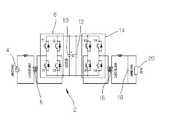
도 1은 종래의 실시예에 따른 정류기-인버터형 무정전 전원투입장치를 나타내는 회로도이다.1 is a circuit diagram showing a rectifier-inverter type uninterruptible power supply device according to a conventional embodiment.
이를 참조하면, 도 1에 도시된 바와 같은 일반적인 단상 고역률 무정전전원장치(2)의 회로는 2개의 leg (T1과 D1는 하나의 leg이며T2와 D2는 또 다른 하나의 leg이다)으로 이루어진 4개의 스위치T1, D1, T2, D2로 구성된 풀-브릿지 (full-bridge) 정류기(8)와; 2개의 leg로 이루어진 4개의 스위치T3, D3, T4, D4로 구성된 풀-브릿지 인버터(14)로 구성되며, 배터리(10)는 직류 콘덴서(12:Cd)와 병렬로 연결된다.Referring to this, the circuit of the general single-phase high power factor
상기 정류기(8)는 역률보상 및 충전기능을 수행하며 인버터(14)는 직류전력을 교류전력으로 변환하는 기능을 수행한다. 즉, 상기 정류기(8)는 스위치T1, D1, T2, D2의 스위칭제어에 의해 교류전력을 직류전력으로 변환시키며, 그 정류기(8)에 병렬로 연결된 상기 직류 콘덴서(12:Cd)에 직류전력이 충전되며, 그 충전전력이 다시 병렬로 접속된 상기 배터리(10)에 충전되게 되게 구성된다.The
또한, 상기 인버터(14)는 스위치T3, D3, T4, D4의 스위칭제어에 의해 상기 배터리(10)에 충전된 직류전력을 교류전력으로 변환하여, 출력변압기(16)를 통해 승압하여 교류출력(18)으로 제공하여 부하(20)에 교류전력을 제공하게 된다.In addition, the
이러한 정류기(8) 및 인버터(14)는 기설정된 스위칭 주파수(switching frequency)에 의해 펄스폭변조(PWM: pulse-width modulation) 방식으로 제어되는 바, 이러한 스위치제어는 일반적인 제어부의 기능이므로 이는 생략한다. The
일반적으로 배터리(10)는 유지 보수, 가격 등의 문제로 많은 배터리를 직렬로 연결하여 계통전압의 최대치까지 올려 사용하지 않는다. 따라서 입력단과 출력단에는 입력전압과 배터리 전압 사이의 전압 균형을 맞추기 위하여 입력단의 변압기(6)가 필요하며, 또한 배터리 전압으로부터 인버터 교류출력 전압을 내기 위하여 출력단의 변압기(16)가 필수적이다. 이와 같이 입력단의 변압기는 높은 입력 교류전압을 낮은 입력 교류전압으로 낮추며 여기에 연결된 정류기(8)는 전류제어를 통해 고역률을 유지하면서 배터리(10)를 충전시킨다. 인버터(14)는 낮은 직류전압을 교류전압으로 만들고, 출력단의 변압기(16)를 통해 필요한 교류전압을 만든다.In general, the
이러한 형태의 무정전전원장치는 변압기(6)(16)에서의 전력손실과, 낮은 직류전압으로 인한 도통손실의 증가로 인하여 시스템의 효율이 저하된다. 일반적으로 시스템의 고장 혹은 과부하 시에는 싸이리스터(thyristor)를 사용하여 입력전압을 출력전압으로 연결해 주는 바이패스(bypass) 회로가 추가적으로 필요하다. 제 1도의 무정전전원장치 회로에서는 이러한 바이패스 회로를 생략한 상태이다.In this type of uninterruptible power supply, the efficiency of the system is lowered due to the increase in power loss in the
본 발명은 상기한 종래 기술의 사정을 감안하여 이루어진 것으로, 태양광 발전장치를 계통연계하고, 입력 및 출력변압기를 제거하고, 발전 및 충방전 leg을 구비함으로써 변압기를 통한 전력손실 및 도통손실을 방지하도록 함으로써 고효율 전력의 제공이 가능하도록 한 태양광 발전장치가 구비된 무정전 전원투입장치를 제공함에 그 목적이 있다.SUMMARY OF THE INVENTION The present invention has been made in view of the above-described circumstances of the prior art, and includes grid-connected photovoltaic devices, eliminates input and output transformers, and includes power and charge and discharge legs to prevent power loss and conduction loss through transformers. It is an object of the present invention to provide an uninterruptible power supply device with a photovoltaic device capable of providing high efficiency power.
상기한 목적을 달성하기 위해, 본 발명의 바람직한 실시예에 따르면 교류입력(4)단과, 부하(20)와 연결된 교류출력(18)단의 사이에, 정류기 leg(32) 및 태양전지(34), 발전leg(36), 배터리(38), 충방전leg(40), 직류전력 저장콘덴서(12) 및, 공통 leg(42), 인버터 leg(44)이 순차적으로 병렬 접속되며, 상기 정류기 leg(32)은 교류입력전압을 직류전압으로 정류하고, 상기 발전leg(36)은 태양전지로부터 발생되는 불규칙한 전압을 승압하고, 상기 충방전leg(40)은 상기 발전 leg(36)을 통해 인입된 전압을 강압하여 배터리(38)에 충전하거나, 배터리(38)의 전압을 승압하여 부하단으로 출력시키며, 상기 직류전력 저장콘덴서(12)는 상기 충방전leg(40)으로부터 출력된 전압을 저장하고, 상기 공통 leg(42)는 스위칭되어 상기 인버터 leg(44)과 정류기 leg(32)을 독립적으로 제어하며, 상기 인버터 leg(44)은 교류 출력을 부하에 공급하는 것을 특징으로 하는 태양광 발전장치가 구비된 무정전 전원투입장치가 제공된다.In order to achieve the above object, according to a preferred embodiment of the present invention, the
바람직하게, 상기 발전 leg(36)은 정전시 부스트 컨버터로 동작하여, 태양전 지(34)의 전압을 승압시켜 출력하는 것을 특징으로 하는 태양광 발전장치가 구비된 무정전 전원투입장치가 제공된다.Preferably, the
바람직하게, 상기 충방전leg(40)은 정전이면서, 부하전력이 태양광 전력보다 작은 경우, 벅 컨버터로 동작하여 배터리(38)에 전압을 강압시켜 충전하는 것을 특징으로 하는 태양광 발전장치가 구비된 무정전 전원투입장치가 제공된다.Preferably, the charging and discharging
바람직하게, 상기 충방전leg(40)은 정전이면서, 부하전력이 태양광 전력보다 작은 경우 또는 태양광 발전이 불가능한 경우에, 부스트 컨버터로 동작하여 배터리(38)의 전압을 승압시켜 부하로 제공하는 것을 특징으로 하는 태양광 발전장치가 구비된 무정전 전원투입장치가 제공된다.Preferably, the charging /
바람직하게, 상기 발전 leg(36)은 계통연결(교류전압입력)시, 부하전력이 태양광 발전보다 작거나 큰 것에 무관하게, 부스트 컨버터로 동작하여, 태양전지(34)의 전압을 승압시켜 출력하는 것을 특징으로 하는 태양광 발전장치가 구비된 무정전 전원투입장치가 제공된다.Preferably, the
바람직하게, 상기 충방전leg(40)은 계통연결(교류전압입력)시, 부하전력이 태양광 발전보다 작거나 크거나, 태양광 발전이 불가능한 것에 무관하게, 벅 컨버터로 동작하여, 배터리(38)로 전압을 강압시켜 충전하게 스위칭되는 것을 특징으로 하는 태양광 발전장치가 구비된 무정전 전원투입장치가 제공된다.Preferably, the charging / discharging
이하, 본 발명에 대해 도면을 참조하여 상세하게 설명한다.EMBODIMENT OF THE INVENTION Hereinafter, this invention is demonstrated in detail with reference to drawings.
도 2는 본 발명의 일실시예에 따른 태양광 발전장치가 구비된 무정전 전원투입장치를 나타내는 회로도이다.2 is a circuit diagram illustrating an uninterruptible power supply device with a photovoltaic device according to an embodiment of the present invention.
이를 참조하면, 본 발명의 일실시예에 따른 태양광 발전장치가 구비된 무정전 전원투입장치(30)는 직류전력 저장 콘덴서(12:Cd)를 중심으로 태양전지(34)로부터 직류전력을 제공하는 태양광발전부(36: 발전 leg이라 함), 배터리를 충방전하는 충방전부(40: 충방전 leg이라 함), 교류입력전압을 직류전압으로 정류하는 정류부(32: 정류기 leg이라 함), 교류출력을 부하에 공급하는 인버터부(44: 인버터 leg이라 함.)로 크게 구성되어져 있다.Referring to this, the
본 발명의 일실시예에 따른 태양광 발전장치가 구비된 무정전 전원투입장치(30)는 교류입력(4)단과, 부하(20)와 연결된 교류출력(18)단의 사이에, 정류기 leg(32) 및 태양전지(34), 발전leg(36), 배터리(38), 충방전leg(40), 직류전력 저장콘덴서(12) 및, 공통 leg(42), 인버터 leg(44)이 순차적으로 병렬 접속되어 제어부(미도시)의 스위칭신호에 따라 각 구성에 포함된 스위치가 제어됨으로써 안정적인 무정전 전원투입장치를 구성한다.The
상기 정류부(32)와 인버터부(44)는 공통 leg(42)를 공유한다. 직류전압은 계통전압에 사용할 수 있는 비교적 높은 전압으로, 태양광발전으로부터 나오는 불규칙한 전압을 발전 leg(36)를 통하여 승압하거나, 낮은 배터리 전압을 충방전 leg(40)를 사용하여 승압하여 얻을 수 있다. 따라서 본 발명의 제안된 회로에서는 종래의 무정전장치에 사용되었던 입력단과 출력단의 변압기를 제거할 수 있다.The rectifying
상기 공통 leg(42)는 저주파수인 입력전원과 동일한 주파수로 스위칭을 하고, 정류기 leg(32)와 인버터 leg(44)를 고주파의 스위칭 주파수로 스위칭을 하면 고정주파수의 가변 교류전원을 얻게 된다.The
상기 공통 leg(42)에 포함된 스위치(T3, D3)들은 입력전원의 주파수로 스위칭을 하면, 정류기 leg(32)와 인버터 leg(44)의 스위치들은 단극성 (unipolar) PWM 방식으로 스위칭하게 되며, 정류기 leg(32)와 인버터 leg(44)의 스위치(T1,D1,T4,D4)들은 서로 독립적으로 제어될 수 있다. 즉 정류기 leg(32)는 입력전류를 제어하기 위한 방향으로 스위칭하며 인버터 leg(44)는 출력전압을 제어하기 위한 방향으로 스위칭하게 된다.When the switches T3 and D3 included in the
상기 발전 leg(36)는 부스트 컨버터(boost convert 혹은 step-up converter)로 동작하여, 불규칙한 태양전지(34) 전압을 계통전압에 사용할 수 있는 직류전압으로 승압한다. 상기 발전 leg(36)의 다이오드D, 스위치S, 인덕터Lp가 조합되어 부스트 컨버터(boost convert 혹은 step-up converter)로 동작된다.The
이때, 부스트 컨버터(boost convert 혹은 step-up converter)는 승압형 컨버터라고도 일컬으며, 스위치 S가 ON된 동안에는 입력전원이 상기 인덕터Lp의 양단에 연결되어 전류의 충전이 이루어지며, 스위치 S가 ON되면 충전된 전류가 부하 측 즉, 상기 충방전 leg(40)측으로 전달된다.In this case, a boost converter (step-up converter) is also referred to as a boost converter. While the switch S is turned on, the input power is connected to both ends of the inductorLp to charge the current, and the switch S is turned on. When the charged current is transferred to the load side, that is, the charge and discharge
상기 충방전 leg(40)는 배터리(38)를 충전할 경우에는 벅 컨버터(buck converter 혹은 step-down converter)로 동작하여 정류 회로를 거친 높은 직류전압을 배터리(38)로 충전하기에 적당한 전압으로 낮춘다. 방전 시에는 반대로 부스트 컨버터로 동작하여 낮은 배터리 전압을 계통전압에 사용할 수 있는 직류전압으로 승압하게 된다.The charging / discharging
즉, 상기 충방전 leg(40)는 충전시 및 방전시에 각각 벅 컨버터(buck converter 혹은 step-down converter) 및 부스트 컨버터(boost convert 혹은 step-up converter)로 동작하여 전압을 강압 또는 승압한다.That is, the charging / discharging
상기 벅 컨버터(buck converter 혹은 step-down converter)는 강압형 컨버터라고도 하며, 일정한 주기로 스위칭되는 스위칭소자를 사용하여 스위치가 ON되는 동안 입력전원이 회로에 연결되고, OFF된 동안에는 회로가 끊어진다. 따라서, 주기적으로 펄스모양의 전압을 평활하여 직류 전압을 출력하여 배터리를 충전시킨다.The buck converter (buck converter or step-down converter) is also referred to as a step-down converter, the input power is connected to the circuit while the switch is turned on by using a switching element that is switched at a constant cycle, the circuit is disconnected while turned off. Therefore, the battery is charged by periodically outputting a DC voltage by smoothing a pulse-shaped voltage.
상기 충방전 leg(40)는 벅 컨버터의 기능으로 배터리(38)를 충전시키며, 부스트 컨버터의 기능으로 배터리(38)의 충전전압을 부하단으로 승압시켜 전달한다.The charging / discharging
본 발명은 정전시 계통전압으로 사용할 수 있는 직류전압을 태양전지(34) 또는 배터리(38) 단독으로 얻거나 태양전지(34)와 배터리(38)를 동시에 사용하여 얻을 수 있기 때문에 배터리(38)를 단독으로 쓰는 경우보다 안정적인 전원을 확보할 수 있다.According to the present invention, the
또한, 태양광발전전력의 잉여전력 발생시 배터리(38)의 충전이 가능하여 정전시 시스템의 동작시간을 연장시킬 수 있다. 또한, 계통과 연결되어 있을 때에는 태양광발전전력으로 배터리의 충전 및 부하전력을 공급할 뿐만 아니라 잉여 전력 발생시 계통으로 전달할 수 있다.In addition, the
이와 같이 본 발명에서 제안된 회로는 시스템의 신뢰성을 향상시킬 수 있을 뿐만 아니라 시스템의 저가격화를 가져올 수 있으며, 입력 및 출력변압기의 제거, 도통손실의 감소, 그리고 태양광발전전력으로 계통전력, 배터리전력 및 부하전력을 직접 공급함으로써 시스템의 효율을 향상시킬 수 있다.As described above, the circuit proposed in the present invention can not only improve the reliability of the system, but also bring down the cost of the system, eliminate the input and output transformers, reduce the conduction loss, and use the grid power and the battery as the photovoltaic power. By directly supplying power and load power, the efficiency of the system can be improved.
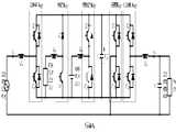
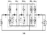
도 3a, 3b, 3c는 본 발명의 일실시예에 따른 태양광 발전장치가 구비된 무정전 전원투입장치를 이용한 정전시 동작상태를 나타내는 전류흐름도이다.3A, 3B, and 3C are current flow diagrams illustrating an operation state during a power failure using an uninterruptible power supply device with a photovoltaic device according to an embodiment of the present invention.
이를 참조하면, 도 3a, 3b, 3c는 정전이 발생될 경우, 본 발명의 전류 흐름도를 나타낸 것으로, 도 3a는 정전시의 전류흐름을 나타낸 것이므로, 교류입력(4)이 이루어지지 않고, 부하전력이 태양광발전보다 적은 경우로, 발전 leg(36)의 다이오드D, 스위치S, 인덕터Lp가 부스트 컨버터로 동작하여 태양전지(34)로부터 나오는 전압을 직류전압Vd로 상승시켜 부하전력을 공급하고 태양광발전전력의 잉여전력은 배터리(38)에 공급된다.3A, 3B, and 3C show a current flow chart of the present invention when a power failure occurs, and since FIG. 3A shows a current flow during power failure, the AC input 4 is not made, and the load power is not shown. In this case, the diodeD , the switchS , and the inductorLp of the
도면에서, 전류가 도통되는 라인은 굵은 실선으로, 도통되지 않는 라인은 얇은 실선으로 도시하도록 한다.In the drawing, a line through which current is conducted is shown by a thick solid line, and a line that is not conducting is shown by a thin solid line.
발전 leg(36)의 스위치S는 일정한 펄스폭변조를 통해 제어되며, 다이오드D는 인덕터Lp에 저장된 에너지를 직류 콘덴서Cd에 공급할 때 도통된다. 충방전 leg(40)는 인덕터Lb와 배터리와 연결되어 벅 컨버터로 동작하여 배터리를 충전시킨다.The switchS of the
즉, 태양광 발전이 부하전력보다 큰 경우이므로, 태양광 발전으로 발생된 전력은 부하전력을 공급하고도 잉여전력이 잔존하게 되므로, 상기 충방전 leg(40)는 스위치(T2)만 도통되고, 스위치(D2)는 도통되지 않아 배터리(38)를 충전하기만 하고, 부하전력을 공급하지 않는다.That is, since the photovoltaic power generation is greater than the load power, the power generated by the photovoltaic power generation surplus power remains even after supplying the load power, the charging and discharging
공통 leg(42)의 스위치(T3, D3)는 인버터 leg(44)의 스위치(T4,D4)와 결합하여 풀-브릿지 구조의 인버터로 동작하며 공통 leg(42)는 출력전압의 주파수로 스위칭하게 되는데, 출력전압이 양의 값일 경우, 공통 leg(42)의 하위 스위치D3는 도통되고 공통 leg(42)의 상위 스위치T3는 소거된다. 인버터 leg(44)의 상위 스위치T4가 도통되면 부하에 직류전압Vd가 인가되고 전류io가 부하 측으로 흐르게 되며 인버터 leg의 하위 스위치D4가 도통되면 부하에 영전압이 인가되고 출력전류는 스위치D3와D4를 통하여 흐르게 된다.The switchesT3 andD3 of the
반대로 출력전압이 음의 값일 경우, 공통 leg(42)의 상위 스위치T3는 도통되고 공통 leg(42)의 하위 스위치D3는 소거된다. 인버터 leg(44)의 상위 스위치T4가 도통되면 부하에 영전압이 인가되고 출력전류는 스위치T3와T4를 통하여 흐르게 된다. 인버터 leg(44)의 하위 스위치D4가 도통되면 부하에 직류전압 -Vd가 인가되어 전류io가 음의 값을 가지게 된다.In contrast, when the output voltage is negative, the upper switchT3 of the
도 3b는 부하전력이 태양광발전보다 큰 경우로, 발전 leg(36)의 다이오드D, 스위치S, 인덕터Lp가 부스트 컨버터로 동작하여 태양전지(34)의 전압을 직류전압 Vd로 승압시키는 동시에 충방전 leg(40)의 상위 스위치T2에 병렬로 연결되어 있는 다이오드, 하위 스위치D2, 인덕터Lb가 부스트 컨버터로 동작하여 배터리의 전압을 직류전압Vd로 승압한다. 인버터의 동작은 도 3a의 동작과 동일하다.3b shows that the load power is greater than that of photovoltaic power generation. The diodeD , the switchS , and the inductorLp of the
즉, 태양광 발전이 부하전력보다 작은 경우이므로, 태양광 발전으로 발생된 전력은 부하전력을 공급하고도 부족전력이 생기게 되며, 상기 충방전 leg(40)는 스위치(T2)는 도통되지 않으며, 스위치(D2)는 도통되어 배터리(38)의 충전전력을 부하전력으로 공급하기만 하고, 배터리(38)를 충전하지는 않는다.That is, since the photovoltaic power generation is smaller than the load power, the power generated by the photovoltaic power generation causes insufficient power even when the load power is supplied, and the charge /
도 3c는 태양광발전이 불가능한 경우로, 정전시이면서 태양광 발전이 불가능하므로 정류기 leg(32)과 발전 leg(36)은 도통되지 않는다. 그 상태에서, 충방전 leg(40)의 상위 스위치T2에 병렬로 연결되어 있는 다이오드, 하위 스위치D2, 인덕터Lb가 부스트 컨버터로 동작하여 배터리(38)의 전압을, 부하에서 필요한 직류전압Vd로 상승시키며 인버터의 동작은 도 3a의 동작과 동일하다.3C is a case in which photovoltaic power generation is not possible, and thus, during power failure, the photovoltaic power generation is impossible, so that the
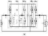
도 4a, 4b, 4c는 본 발명의 일실시예에 따른 태양광 발전장치가 구비된 무정전 전원투입장치를 이용한 계통 연결시 태양광 발전 및 배터리 충전상태를 나타내는 전류흐름도이다.4A, 4B, and 4C are diagrams illustrating current flows showing solar power generation and battery charging states when grids are connected using an uninterruptible power supply device having a photovoltaic device according to an embodiment of the present invention.
이를 참조하면, 도 4a, 4b, 4c는 본 발명의 장치가 계통에 연결된 경우를 나타낸 전류 흐름도로서, 도 4a는 부하전력이 태양광발전보다 적은 경우로, 발전 leg(36)의 다이오드D, 스위치S, 인덕터Lp가 부스트 컨버터로 동작하여 태양전지 의 전압을 직류전압Vd로 상승시켜 부하전력을 공급하고 태양광발전전력의 잉여전력은 배터리(38) 및 계통으로 공급된다.Referring to this, FIG. 4a, 4b, 4c includes a diodeD, the switch of a current flow chart showing a case in which the apparatus of the invention connected to the grid, in case Figure 4a is a load power less than solar power, power leg (36)S , the inductorLp acts as a boost converter to increase the voltage of the solar cell to the DC voltageVd to supply the load power, the surplus power of the photovoltaic power is supplied to the
여기서 정류기 leg(32)의 스위치(T1,D1)는 공통 leg(42)의 스위치(T3,D3)와 결합하여 풀-브릿지 인버터로 동작하여 직류전압을 교류입력전압으로 변환한다. 이와 유사하게, 인버터 leg(44)의 스위치(T4,D4)도 공통 leg(42)의 스위치(T3,D3)와 결합하여 풀-브릿지 인버터로 동작하여 직류전압을 교류출력전압으로 변환한다.Here, the switchesT1 andD1 of the
이들 정류기 leg(32)의 스위치(T1,D1)와 인버터 leg(44)의 스위치(T4,D4)의 동작 원리는 정전시 인버터 동작과 동일하다. 충방전 leg(40)는 인덕터Lb와 배터리와 연결되어 벅 컨버터로 동작하여 배터리를 충전시킨다. 즉, 충방전 leg(40)의 상위 스위치T2는 일정한 펄스폭변조를 통해 제어되며, 하위 스위치D2는 항상 소거되고 여기에 연결된 바디 다이오드(body diode)는 인덕터Lb의 전류를 순환시킬 때 도통된다.The operation principle of the switchesT1 andD1 of the
도 4b는 부하전력이 태양광발전보다 큰 경우로, 정류기 leg(32)와 공통 leg(42)가 결합하여 풀-브릿지 컨버터를 이루어 교류입력전압을 높은 직류전압Vd로 변환할 뿐만 아니라 발전 leg(36)의 다이오드D, 스위치S, 인덕터Lp가 부스트 컨버터로 동작하여 태양전지(34)의 전압을 직류전압Vd로 상승시켜 배터리 충전 및 부하전력을 공급한다. 공통 leg(42)는 입력전압의 주파수로 스위칭하게 되는데, 입력 전압이양의 값일 경우, 공통 leg(42)의 하위 스위치D3는 도통되고 공통 leg(42)의 상위 스위치T3는 소거된다.Figure 4b is a case where the load power is greater than the photovoltaic power generation, the
반대로 입력전압이음의 값일 경우, 공통 leg(42)의 상위 스위치T3는 도통되고 공통 leg의 하위 스위치D3는 소거된다. 입력전압이 양의 값일 경우, 정류기 leg(32)의 하위 스위치D1이 도통되고 정류기 leg(32)의 상위 스위치T1이 소거되면, 인덕터의 전류is가 양의 방향으로 증가하고 자기에너지는 인덕터Ls에 저장된다. 정류기 leg(32)의 상위 스위치T1이 도통되고 하위 스위치D1이 소거되면 인덕터Ls에 저장된 자기에너지는 직류 측으로 전달된다.On the contrary, when the input voltage is negative, the upper switchT3 of the
즉, 태양광 발전이 부하전력보다 크거나, 작은 경우라도, 도 4a 및 4b는 정전시가 아니고 계통연결시이므로, 상기 충방전 leg(40)는 스위치(T2)만 도통되고, 스위치(D2)는 도통되지 않아 배터리(38)를 충전하기만 하고, 부하전력을 공급하지 않는다.That is, even when photovoltaic power generation is larger or smaller than the load power, since FIG. 4A and FIG. 4B are not at power failure but at grid connection, the charge /
입력전압이 음의 값을 가질 때도 같은 원리로 동작을 한다. 충방전 leg(40) 및 인버터 leg(44)의 동작은 도 4a의 경우와 동일하다. 도 4c는 태양광발전이 불가능한 경우로, 정류기 leg(32), 충방전 leg(40) 및 인버터 leg(44)의 동작은 도 4a와 동일하며, 발전 leg(36)은 도통되지 않는다.The same principle works when the input voltage is negative. The operation of the charge /
한편, 본 발명의 실시예에 따른 태양광 발전장치가 구비된 무정전 전원투입 장치는 단지 상기한 실시예에 한정되는 것이 아니라 그 기술적 요지를 이탈하지 않는 범위내에서 다양한 변경이 가능하다.On the other hand, the uninterruptible power supply device with a photovoltaic device according to an embodiment of the present invention is not limited only to the above embodiment, but various modifications can be made without departing from the technical gist of the present invention.
상기한 바와 같이, 본 발명에 따른 태양광 발전장치가 구비된 무정전 전원투입장치는 태양전지 및 배터리가 함께 구비되어져 있으며, 변압기를 생략하고 승압 및 강압이 가능하도록 한 장치이므로, 변압기에서 발생되는 도통손실을 감소시킬 수 있으며, 태양광 발전과 배터리를 연계하여 보다 안정적인 전력의 공급이 가능하다는 장점이 있다.As described above, the uninterruptible power supply device with a solar power generation device according to the present invention is provided with a solar cell and a battery, and is a device to omit the transformer and to enable step-up and step-down, and thus, conduction generated from the transformer Loss can be reduced, and there is an advantage in that it is possible to supply more stable power by connecting solar power and battery.
Claims (6)
Translated fromKoreanPriority Applications (1)
| Application Number | Priority Date | Filing Date | Title |
|---|---|---|---|
| KR1020060118437AKR100844401B1 (en) | 2006-11-28 | 2006-11-28 | Uninterruptible Power Supply with Solar Power Generator |
Applications Claiming Priority (1)
| Application Number | Priority Date | Filing Date | Title |
|---|---|---|---|
| KR1020060118437AKR100844401B1 (en) | 2006-11-28 | 2006-11-28 | Uninterruptible Power Supply with Solar Power Generator |
Publications (2)
| Publication Number | Publication Date |
|---|---|
| KR20070001031A KR20070001031A (en) | 2007-01-03 |
| KR100844401B1true KR100844401B1 (en) | 2008-07-07 |
Family
ID=37868687
Family Applications (1)
| Application Number | Title | Priority Date | Filing Date |
|---|---|---|---|
| KR1020060118437AActiveKR100844401B1 (en) | 2006-11-28 | 2006-11-28 | Uninterruptible Power Supply with Solar Power Generator |
Country Status (1)
| Country | Link |
|---|---|
| KR (1) | KR100844401B1 (en) |
Cited By (1)
| Publication number | Priority date | Publication date | Assignee | Title |
|---|---|---|---|---|
| KR101207595B1 (en) | 2012-08-24 | 2012-12-03 | 이민수 | Cooling system of sealer |
Families Citing this family (6)
| Publication number | Priority date | Publication date | Assignee | Title |
|---|---|---|---|---|
| KR100867650B1 (en)* | 2008-01-11 | 2008-11-10 | 김배영 | Peak control and power surveillance application of power plant synchronizer application |
| DE102008059293A1 (en)* | 2008-11-27 | 2010-06-02 | Manßhardt, Hans | Solar power generation unit for generating controlled, sinusoidal alternating voltage, has combination consisting of photovoltaic module, solar power buffer storage, regulating and switching module, input converter and output converter |
| CN106532536A (en)* | 2016-11-02 | 2017-03-22 | 上海金友金弘智能电气股份有限公司 | Intensive intelligent photovoltaic prefabricated substation |
| CN108683346A (en)* | 2018-07-25 | 2018-10-19 | 汉能移动能源控股集团有限公司 | Converter and solar power generation system |
| CN113629852A (en)* | 2021-08-20 | 2021-11-09 | 江苏亿万物联科技有限公司 | Method for using photovoltaic power and plant power complementary as power source for hydrogen production equipment |
| KR102623576B1 (en)* | 2023-07-11 | 2024-01-10 | 이노크리시스템 주식회사 | Uninterruptible power supply system |
Citations (4)
| Publication number | Priority date | Publication date | Assignee | Title |
|---|---|---|---|---|
| JPH08336240A (en)* | 1995-06-07 | 1996-12-17 | Nippon Telegr & Teleph Corp <Ntt> | Uninterruptible solar power generation system |
| JP2000217273A (en) | 1999-01-22 | 2000-08-04 | Ntt Power & Building Facilities Inc | Ac uninterruptible power system |
| KR200234406Y1 (en)* | 2001-03-29 | 2001-10-10 | 주식회사 하이테크 | Complex power generation system for minor electric capacity |
| KR20040055061A (en)* | 2002-12-20 | 2004-06-26 | 한국수자원공사 | Automatic Power Supply Device of an Unmanned Observatory |
- 2006
- 2006-11-28KRKR1020060118437Apatent/KR100844401B1/enactiveActive
Patent Citations (4)
| Publication number | Priority date | Publication date | Assignee | Title |
|---|---|---|---|---|
| JPH08336240A (en)* | 1995-06-07 | 1996-12-17 | Nippon Telegr & Teleph Corp <Ntt> | Uninterruptible solar power generation system |
| JP2000217273A (en) | 1999-01-22 | 2000-08-04 | Ntt Power & Building Facilities Inc | Ac uninterruptible power system |
| KR200234406Y1 (en)* | 2001-03-29 | 2001-10-10 | 주식회사 하이테크 | Complex power generation system for minor electric capacity |
| KR20040055061A (en)* | 2002-12-20 | 2004-06-26 | 한국수자원공사 | Automatic Power Supply Device of an Unmanned Observatory |
Cited By (1)
| Publication number | Priority date | Publication date | Assignee | Title |
|---|---|---|---|---|
| KR101207595B1 (en) | 2012-08-24 | 2012-12-03 | 이민수 | Cooling system of sealer |
Also Published As
| Publication number | Publication date |
|---|---|
| KR20070001031A (en) | 2007-01-03 |
Similar Documents
| Publication | Publication Date | Title |
|---|---|---|
| KR101116428B1 (en) | Energy Storage System | |
| TWI221695B (en) | Uninterruptible power system | |
| US6930897B2 (en) | Fuel cell inverter | |
| AU2012302148B2 (en) | Twin boost converter with integrated charger for ups | |
| KR100844401B1 (en) | Uninterruptible Power Supply with Solar Power Generator | |
| CN103828186A (en) | Single-battery power topologies for online UPS systems | |
| KR20120063513A (en) | Electrical energy conversion circuit device | |
| KR101394712B1 (en) | Single-phase BESS power converter for extending battery life and power supply method | |
| Mozaffari et al. | A single-phase inverter/rectifier topology with suppressed double-frequency ripple | |
| Ryu et al. | Test bed implementation of 380V DC distribution system using isolated bidirectional power converters | |
| JPH06266458A (en) | Photovoltaic power generating equipment capable of jointly using battery | |
| KR20180054021A (en) | bidirectional DC-DC converter, and energy storage system including the same | |
| KR101609245B1 (en) | Apparatus for storing energy | |
| Chen et al. | Development of an autonomous distributed maximum power point tracking PV system | |
| CN107342603B (en) | Battery control circuit for power generation system using renewable energy | |
| KR101764651B1 (en) | Power applying apparatus and method for controlling connecting photovoltaic power generating apparatus | |
| CN201018313Y (en) | A home solar power supply system | |
| JP2021027749A (en) | Charge/discharge control device, battery including the same, and dc power supply system | |
| KR20080032839A (en) | Multi-functional online uninterruptible power supply by common DC power | |
| JP4370965B2 (en) | Power converter | |
| KR101643705B1 (en) | Apparatus and method for controlling ups | |
| TWI547062B (en) | DC power supply recovery system | |
| JP6722295B2 (en) | Power conversion system, power supply system, and power conversion device | |
| KR101256376B1 (en) | Energy storage apparatus for using different charging/discharging path, and energy storage system thereof | |
| KR102761198B1 (en) | System-linked energy storage system and power control apparatus |
Legal Events
| Date | Code | Title | Description |
|---|---|---|---|
| A201 | Request for examination | ||
| PA0109 | Patent application | Patent event code:PA01091R01D Comment text:Patent Application Patent event date:20061128 | |
| PA0201 | Request for examination | ||
| PG1501 | Laying open of application | ||
| E902 | Notification of reason for refusal | ||
| PE0902 | Notice of grounds for rejection | Comment text:Notification of reason for refusal Patent event date:20080129 Patent event code:PE09021S01D | |
| E701 | Decision to grant or registration of patent right | ||
| PE0701 | Decision of registration | Patent event code:PE07011S01D Comment text:Decision to Grant Registration Patent event date:20080530 | |
| GRNT | Written decision to grant | ||
| PR0701 | Registration of establishment | Comment text:Registration of Establishment Patent event date:20080701 Patent event code:PR07011E01D | |
| PR1002 | Payment of registration fee | Payment date:20080701 End annual number:3 Start annual number:1 | |
| PG1601 | Publication of registration | ||
| PR1001 | Payment of annual fee | Payment date:20110429 Start annual number:4 End annual number:4 | |
| PR1001 | Payment of annual fee | Payment date:20120629 Start annual number:5 End annual number:5 | |
| FPAY | Annual fee payment | Payment date:20130613 Year of fee payment:6 | |
| PR1001 | Payment of annual fee | Payment date:20130613 Start annual number:6 End annual number:6 | |
| FPAY | Annual fee payment | Payment date:20140625 Year of fee payment:7 | |
| PR1001 | Payment of annual fee | Payment date:20140625 Start annual number:7 End annual number:7 | |
| PR1001 | Payment of annual fee | Payment date:20150629 Start annual number:8 End annual number:8 | |
| FPAY | Annual fee payment | Payment date:20160616 Year of fee payment:9 | |
| PR1001 | Payment of annual fee | Payment date:20160616 Start annual number:9 End annual number:9 | |
| FPAY | Annual fee payment | Payment date:20170519 Year of fee payment:10 | |
| PR1001 | Payment of annual fee | Payment date:20170519 Start annual number:10 End annual number:10 | |
| FPAY | Annual fee payment | Payment date:20180425 Year of fee payment:11 | |
| PR1001 | Payment of annual fee | Payment date:20180425 Start annual number:11 End annual number:11 | |
| FPAY | Annual fee payment | Payment date:20190722 Year of fee payment:12 | |
| PR1001 | Payment of annual fee | Payment date:20190722 Start annual number:12 End annual number:12 | |
| PR1001 | Payment of annual fee | Payment date:20200617 Start annual number:13 End annual number:13 | |
| PR1001 | Payment of annual fee | Payment date:20210624 Start annual number:14 End annual number:14 | |
| PR1001 | Payment of annual fee | Payment date:20220630 Start annual number:15 End annual number:15 | |
| PR1001 | Payment of annual fee | Payment date:20240618 Start annual number:17 End annual number:17 | |
| PR1001 | Payment of annual fee | Payment date:20250428 Start annual number:18 End annual number:18 |