KR100843818B1 - Still Image Imaging Apparatus and Imaging Method - Google Patents
Still Image Imaging Apparatus and Imaging MethodDownload PDFInfo
- Publication number
- KR100843818B1 KR100843818B1KR1020037005504AKR20037005504AKR100843818B1KR 100843818 B1KR100843818 B1KR 100843818B1KR 1020037005504 AKR1020037005504 AKR 1020037005504AKR 20037005504 AKR20037005504 AKR 20037005504AKR 100843818 B1KR100843818 B1KR 100843818B1
- Authority
- KR
- South Korea
- Prior art keywords
- still image
- light
- focusing
- infrared
- imaging
- Prior art date
- Legal status (The legal status is an assumption and is not a legal conclusion. Google has not performed a legal analysis and makes no representation as to the accuracy of the status listed.)
- Expired - Fee Related
Links
Images


Classifications
- H—ELECTRICITY
- H04—ELECTRIC COMMUNICATION TECHNIQUE
- H04N—PICTORIAL COMMUNICATION, e.g. TELEVISION
- H04N23/00—Cameras or camera modules comprising electronic image sensors; Control thereof
- H04N23/60—Control of cameras or camera modules
- H04N23/67—Focus control based on electronic image sensor signals
- H04N23/673—Focus control based on electronic image sensor signals based on contrast or high frequency components of image signals, e.g. hill climbing method
- G—PHYSICS
- G02—OPTICS
- G02B—OPTICAL ELEMENTS, SYSTEMS OR APPARATUS
- G02B7/00—Mountings, adjusting means, or light-tight connections, for optical elements
- G02B7/28—Systems for automatic generation of focusing signals
- G02B7/30—Systems for automatic generation of focusing signals using parallactic triangle with a base line
- G02B7/32—Systems for automatic generation of focusing signals using parallactic triangle with a base line using active means, e.g. light emitter
Landscapes
- Physics & Mathematics (AREA)
- Engineering & Computer Science (AREA)
- Multimedia (AREA)
- Signal Processing (AREA)
- General Physics & Mathematics (AREA)
- Optics & Photonics (AREA)
- Studio Devices (AREA)
- Automatic Focus Adjustment (AREA)
- Blocking Light For Cameras (AREA)
- Transforming Light Signals Into Electric Signals (AREA)
- Focusing (AREA)
- Viewfinders (AREA)
- Indication In Cameras, And Counting Of Exposures (AREA)
Abstract
Translated fromKorean
Description
Translated fromKorean본 발명은 CCD(Charge Coupled Device) 이미지 센서 등의 광전 변환 소자를 이용하여 전자적으로 정지 화상을 촬상하는 정지 화상 촬상 장치 및 방법에 관한 것이다.BACKGROUND OF THE
종래, CCD(Charge Coupled Device) 이미지 센서를 광전 변환 소자로서 이용한 소위 디지털 스틸 카메라라고 하는 전자식 정지 화상 촬상 장치가 널리 이용되고 있다.BACKGROUND ART Conventionally, an electronic still image pickup device called a digital still camera using a CCD (Charge Coupled Device) image sensor as a photoelectric conversion element has been widely used.
이러한 종류의 디지털 스틸 카메라에서도, 통상의 은염(銀鹽) 필름을 이용한 카메라와 마찬가지로, 야간이나 암소(暗所) 등의 저조도 환경에서의 광량 부족을 보충하기 위해, 플래시 기능이나 저속 셔터 기능 등이 갖추어져 있다. 플래시 기능은, 예를 들면 크세논 램프와 같은 방전관을 이용하여, 강한 빛의 섬광을 발광시켜, 피사체에 빛을 조사하는 기능이다. 또한, 저속 셔터 기능이란, CCD에의 전하 축적을 장시간 행하는 기능이다.In this type of digital still camera, like a camera using a silver salt film, a flash function and a slow shutter function are provided to compensate for a lack of light in a low-light environment such as at night or in a dark place. Equipped The flash function is a function of irradiating light onto a subject by emitting a strong flash of light using a discharge tube such as a xenon lamp. The slow shutter function is a function of carrying out charge accumulation on the CCD for a long time.
디지털 스틸 카메라에서는, 파인더에 예를 들면 액정 패널 등을 이용하여 CCD에서 검출한 화상을 표시하고 있는 경우, 저조도 환경에서는 촬영 전의 피사체 화상을 파인더에 표시할 수 없다. 즉, 저조도 환경에서는 비록 스틸 화상 촬영이 가능하다고 해도, 사용자가 피사체의 위치나 구도를 촬영 전에 확인하기 위해 파인더에 촬상 화상을 표시하는 프레이밍 처리를 행하는 것까지는 할 수 없다.In a digital still camera, when an image detected by a CCD is displayed in the finder using a liquid crystal panel or the like, in a low light environment, the subject image before shooting cannot be displayed in the finder. In other words, even in a low light environment, even if still image shooting is possible, the user cannot perform a framing process of displaying the captured image in the finder to confirm the position or composition of the subject before shooting.
이러한 문제를 해결하기 위해, 최근 적외선을 피사체에 조사함과 함께 적외선 차단 필터를 광로로부터 대피시킨 상태에서 프레이밍 처리를 행하는 적외선 촬영 기능이 갖추어진 디지털 스틸 카메라가 제안되고 있다.In order to solve this problem, a digital still camera equipped with an infrared photographing function that performs a framing process while irradiating infrared rays to a subject and evacuating an infrared cut filter from an optical path has recently been proposed.
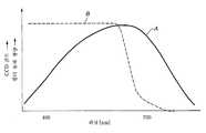
도 1에, CCD의 파장 감도 특성 A와, 적외선 차단 필터의 파장 통과 특성 B를 도시한다. 도 1에 도시한 바와 같이, CCD는 가시광뿐만 아니라 파장이 약 700㎚ 이상의 적외선에 대해서도 충분히 감도가 있다. 이것에 대하여, 적외선 차단 필터는, 파장이 약 700㎚ 이상의 적외선은 통과하지 않는다. 통상의 촬영시에는, 적외선으로는 노광해서는 안되므로, 적외선 차단 필터가 촬영광의 광로 내에 삽입된 상태로 되어 있다. 이것에 대하여, 적외선 촬영은 이 적외선 차단 필터를 광로 밖으로 대피시키고, 또한 카메라 본체에 형성된 적외선 발광 수단으로부터 적외선을 피사체에 조사하며, 그 반사광을 촬영하는 것이다. 따라서, 이러한 적외선 촬영 기능이 갖추어진 디지털 스틸 카메라에서는, 프레이밍 처리시에는 적외선 촬영을 행하고, 스틸 화상 촬영시에는 적외선 발광을 멈추고, 대신에 플래시 기능 또는 저속 셔터를 이용한 가시광 촬영을 행하며, 이에 의해 저조도 환경에서도 피사체의 위치나 구도를 촬영 전에 확인할 수 있어, 사용자의 희망대로 피사체를 프레임 내에 둘 수 있도록 하고 있다.1 shows the wavelength sensitivity characteristic A of the CCD and the wavelength passing characteristic B of the infrared cut filter. As shown in Fig. 1, the CCD is sufficiently sensitive to not only visible light but also infrared light having a wavelength of about 700 nm or more. On the other hand, the infrared cut filter does not pass the infrared rays whose wavelength is about 700 nm or more. At the time of normal photography, since it should not expose with infrared rays, the infrared cut filter is in the state inserted in the optical path of imaging light. On the other hand, infrared imaging evacuates this infrared cut-off filter out of an optical path, irradiates an infrared ray to a subject from the infrared light emitting means provided in the camera main body, and image | photographs the reflected light. Therefore, in a digital still camera equipped with such an infrared photographing function, infrared photographing is performed during the framing process, infrared emission is stopped during still image capturing, and instead, visible light photographing using a flash function or a slow shutter is performed. In the environment, the position and composition of the subject can be checked before shooting, so that the subject can be placed in the frame as desired by the user.
그런데, 디지털 스틸 카메라에는 일반적으로 자동적으로 포커스가 맞춰지는 오토포커스 기능이 갖추어져 있다. 디지털 스틸 카메라의 오토포커스의 방식에는 다양한 방식이 있다. 그 중 하나로서, 포커스가 맞는 화상은 포커스가 안 맞는 화상보다도 고주파 성분이 많다는 화상 특성을 이용한 자기 초점 검출 방식이 있다. 이 자기 초점 검출 방식은, 포커스 렌즈의 위치를 이동시키면서 실제의 촬상 화상의 고주파 성분을 검출하고, 고주파 성분이 가장 높은 렌즈 위치에 집점점을 설정하는 방식이다.By the way, digital still cameras are generally equipped with an autofocus function that is automatically focused. There are many ways to autofocus digital still cameras. As one of them, there is a self-focus detection method using an image characteristic that a focused image has more high frequency components than an unfocused image. This self-focus detection method is a method of detecting the high frequency component of an actual picked-up image, moving a focus lens position, and setting a focal point in the lens position with the highest high frequency component.
그러나, 렌즈에는 색 수차가 존재하며, 적외선과 가시광으로는 촛점 거리가 서로 다르다. 그 때문에, 예를 들면 동일한 위치로부터 동일한 피사체를 촬상했다고해도, 적외선 촬영시와 가시광 촬영 시에는 포커스 렌즈의 합초 위치가 서로 다르다. 따라서, 프레이밍 처리시에는 적외선 촬영을 행하고, 스틸 화상 촬영시에는 플래시 등을 이용한 가시광 촬영을 행한 경우, 적외선 촬상 화상에 기초하여 자기 초점 검출 방식으로 오토포커스를 행한 것으로는, 포커스가 어긋난 스틸 화상이 촬영된다.However, chromatic aberration exists in the lens, and the focal length is different from infrared and visible light. Therefore, even if the same subject is imaged from the same position, for example, the focusing position of the focus lens is different at the time of infrared imaging and at the time of visible light imaging. Therefore, when infrared imaging is performed during the framing process and visible light imaging using a flash or the like during still image shooting, autofocus is performed by the self-focus detection method based on the infrared captured image. Is photographed.
또한, 적외선을 오프한 자연광만으로 오토포커스를 행했다고 해도, 저조도 상태에서는 콘트라스트가 매우 낮은 화상으로 되므로, 자기 초점 검출 방식을 이용하여 합초 위치를 검출하는 것 자체가 처음부터 곤란하다.In addition, even if autofocus is performed only with natural light with infrared rays off, since the contrast is very low in low light conditions, it is difficult to detect the focal position from the beginning using the self-focus detection method.
이상과 같이, 프레이밍 처리시에는 적외선 촬영을 행하고, 스틸 화상 촬영시에는 플래시 등을 이용한 가시광 촬영을 행한 경우, 스틸 화상의 초점 위치를 검출하는 오토포커스 처리를 정확하게 행하는 것은 매우 어려웠다.As described above, when infrared imaging is performed during the framing process and visible light imaging using a flash or the like during the still image shooting, it is very difficult to accurately perform the autofocus processing for detecting the focus position of the still image.
본 발명의 목적은, 암소 촬영 등의 저조도 환경에 있어도, 파인더에 촬상 대상으로 되는 피사체 화상을 표시시켜 사용자에게 촬영 화상 내용을 확인시키는 프레이밍 처리를 가능하게 하고, 또한 그 후 플래시 조사나 저속 셔터로 가시광 촬영을 행한 경우에도, 정확한 포커싱을 가능하게 한 정지 화상 촬상 장치 및 정지 화상 촬상 방법을 제공하는 것에 있다.An object of the present invention is to enable a framing process for displaying a subject image to be captured in a finder and confirming the contents of a shot image even in a low light environment such as cow photography, and then using flash irradiation or a slow shutter. The present invention also provides a still image image pickup device and still image image pickup method that enable accurate focusing even when visible light imaging is performed.
본 발명에 따른 정지 화상 촬상 장치는, 피사체로부터의 촬상광이 입사되고, 이 입사된 촬상광을 전기 신호로 변환하여 화상을 촬상하는 광전 변환 소자와, 광전 변환 소자에 의해 촬상되어 있는 화상을 표시하는 파인더와, 촬상광의 광로에 대하여 삽입 및 대피가 가능하게 제공되고, 촬상광의 적외선 성분을 제거하는 적외선 제거 필터와, 피사체에 대하여 적외선을 조사하는 적외선 발광부와, 피사체에 대하여 가시광을 조사하는 보조광 조사부와, 광전 변환 소자에 의해 촬상된 정지 화상을 기록하는 기록부와, 파인더에 촬상 대상으로 되는 피사체 화상을 표시하는 프레이밍 처리, 광전 변환 소자에 의해 촬상된 촬상 화상에 기초하여 포커스 렌즈의 합초 위치를 검출하는 포커싱 처리, 정지 화상을 촬상하여 기록하는 정지 화상 촬상 처리의 각 처리의 전환에 대응하여, 각 부를 제어하는 메인 제어부를 구비한다. 메인 제어부는, 프레이밍 처리시에는 적외선 제거 광학 필터를 광로밖으로 대피시킴과 함께 적외광 발광부로부터 적외광을 발광시키고, 포커싱 처리시에는 적외광 발광부로부터의 적외광의 발광을 정지시킴과 함께 보조광 조사부로부터 가시광을 발광시키고, 정지 화상 촬상 처리시에는 적외광 제거 광학 필터를 광로 내에 삽입함과 함께 포커싱 처리 시에 검출한 합초 위치에 포커스 렌즈를 이동시켜 정지 화상을 촬상시킨다.A still image image pickup device according to the present invention displays a photoelectric conversion element that receives image pickup light from a subject, converts the incident image input light into an electrical signal, and picks up an image, and an image captured by the photoelectric conversion element. A finder, an infrared ray elimination filter for removing the infrared component of the imaging light, an infrared light emitting portion for irradiating infrared rays to the subject, and an auxiliary light for irradiating visible light to the subject; The focusing position of the focus lens is based on the irradiation unit, the recording unit for recording the still image picked up by the photoelectric conversion element, the framing process for displaying the subject image to be picked up in the finder, and the captured image picked up by the photoelectric conversion element. Each process of the focusing process to detect and the still image pick-up process which picks up and records a still image In response to the switch, and a main control unit for controlling each section. In the framing process, the main control unit escapes the infrared light removing optical filter out of the optical path, emits infrared light from the infrared light emitting unit, and stops the emission of infrared light from the infrared light emitting unit during the focusing process. Visible light is emitted from the irradiating portion, and during the still image imaging process, an infrared light removing optical filter is inserted into the optical path, and the focus lens is moved to the in-focus position detected during the focusing process to capture the still image.
본 발명에 따른 정지 화상 촬상 장치에서는, 적외선 촬상에 의해 프레이밍 처리를 행하고, 정지 화상 촬영 처리에는 플래시 또는 저속 셔터 등을 이용하여 가시광 촬영을 행한다. 오토포커스시에는, 적외선의 발광을 정지시킴과 함께 피사체에 대하여 보조용 가시광을 조사하여 행한다.In the still image imaging apparatus according to the present invention, framing processing is performed by infrared imaging, and visible light imaging is performed using a flash or a slow shutter for the still image shooting processing. At the time of autofocusing, light emission of infrared rays is stopped and auxiliary visible light is irradiated to the subject.
본 발명에 따른 정지 화상 촬상 방법은, 광전 변환 소자를 이용하여 정지 화상을 전자적으로 촬상하는 정지 화상 촬상 방법으로서, 파인더에 촬상 대상으로 되는 피사체 화상을 표시하는 프레이밍 처리, 광전 변환 소자에 의해 촬상된 촬상 화상에 기초하여 포커스 렌즈의 합초 위치를 검출하는 포커싱 처리, 정지 화상을 촬상하여 기록하는 정지 화상 촬상 처리의 각 처리를, 사용자의 선택 조작 또는 자동 선택에 대응하여 전환하고, 프레이밍 처리시에는 촬상광의 적외선 성분을 제거하는 적외선 제거 광학 필터를 광로밖으로 대피시킴과 함께 피사체에 대하여 적외광을 조사하고, 포커싱 처리시에는 적외광의 발광을 정지시킴과 함께, 피사체에 대하여 보조용 가시광을 조사하여, 정지 화상 촬상시에는 적외광 제거 광학 필터를 광로 상에 삽입함과 함께 상기 포커싱 처리 시에 검출한 합초 위치에 포커스 렌즈를 이동시켜 정지 화상을 촬상한다.The still image pick-up method according to the present invention is a still image pick-up method for electronically picking up a still image using a photoelectric conversion element, which is picked up by a framing process for displaying a subject image to be picked up in a finder and a photoelectric conversion element. The focusing processing for detecting the focusing position of the focus lens and the still image imaging processing for capturing and recording still images are switched in response to the user's selection operation or automatic selection based on the captured image, and the image is captured during the framing process. Evacuate the infrared-removing optical filter that removes the infrared components of the light out of the optical path, irradiate the infrared light to the subject, stop the emission of the infrared light during the focusing process, and irradiate the auxiliary visible light to the subject. In the case of still image capturing, an infrared light removing optical filter is inserted in the optical path By moving the focus lens to the in-focus point is detected at the time of the focusing process picks up a still image.
본 발명에 따른 정지 화상 촬상 방법에서는, 적외선 촬상에 의해 프레이밍 처리를 행하여, 정지 화상 촬영 처리에는 플래시 또는 저속 셔터 등을 이용하여 가시광 촬영을 행한다. 오토포커스시에는, 적외선의 발광을 정지시킴과 함께 피사체에 대하여 보조용 가시광을 조사하여 행한다.In the still image imaging method according to the present invention, framing processing is performed by infrared imaging, and visible light imaging is performed by using a flash or a slow shutter for the still image shooting process. At the time of autofocusing, light emission of infrared rays is stopped and auxiliary visible light is irradiated to the subject.
본 발명의 또 다른 목적, 본 발명에 의해 얻어지는 구체적인 이점은, 이하에서 도면을 참조하여 설명되는 실시예의 설명으로부터 한층 명백해질 것이다.Further objects of the present invention and specific advantages obtained by the present invention will become more apparent from the description of the embodiments described below with reference to the drawings.
도 1은 CCD 및 적외선 차단 필터의 파장-감도 특성을 도시한 도면.1 shows wavelength-sensitivity characteristics of a CCD and an infrared cut filter.
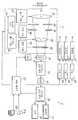
도 2는 본 발명을 적용한 디지털 스틸 카메라의 구성도.2 is a block diagram of a digital still camera to which the present invention is applied.
도 3은 통상 동작 모드에서의 동작 시퀀스를 도시한 흐름도.3 is a flowchart showing an operation sequence in a normal operation mode.
도 4는 저조도 동작 모드에서의 동작 시퀀스를 도시한 흐름도.4 is a flowchart showing an operation sequence in a low light operating mode.
이하, 본 발명을 전자적으로 정지 화상을 촬상하는 디지털 스틸 카메라에 적용하여 예를 들어 설명한다.Hereinafter, the present invention will be described with reference to an example by applying it to a digital still camera which captures a still image electronically.
본 발명이 적용된 디지털 스틸 카메라(1)는, 도 2에 도시한 바와 같은 구성을 갖춘 것이다.The
즉, 본 발명이 적용된 디지털 스틸 카메라(1)는, 도 2에 도시한 바와 같이 렌즈부(11)와, CCD(12)와, 타이밍 신호 발생 회로(TG : 13)와, 아날로그 신호 처리 회로(14)와, 아날로그/디지털 변환 회로(A/D)(15)와, 디지털 신호 처리 회로(16)와, 파인더(17)와, 기록 회로(18)와, 셔터 개방 버튼(19)과, 모드 전환 스위치(20)와, 플래시 발광부(21)와, 플래시 구동 회로(22)와, AF용 보조광 발광부(23)와, AF용 보조광 구동 회로(24)와, 적외선 발광부(25)와, 적외선 구동 회로(26)와, 메인 제어부(27)를 포함하고 있다.That is, the
CCD(12)는 렌즈부(11)를 통하여 수광면에 결상된 피사체의 촬상광을, 화소마 다 전기 신호로 변환하고, 1 화면분의 화상 신호를 출력한다. CCD(12)에 의해 출력된 화상 신호는 아날로그 신호 처리 회로(14)로 공급된다.The CCD 12 converts the imaging light of the subject formed on the light receiving surface through the
타이밍 신호 발생 회로(13)는 CCD(12)가 1 화면마다의 화상 신호의 축적 및 판독에 필요한 각종 구동 펄스를 발생시킨다. 타이밍 신호 발생 회로(13)로부터 발생된 각종 펄스는 CCD(12)로 공급되고, 화상 신호의 촬상 처리나 출력 처리의 타이밍 신호로서 이용된다.The timing
아날로그 신호 처리 회로(14)는 CCD(12)로부터 공급된 화상 신호에 대하여, 샘플링 처리나 증폭 처리 등의 아날로그 처리를 행한다. 아날로그 신호 처리 회로(13)로부터 출력된 화상 신호는 아날로그/디지털 변환 회로(15)로 공급된다.The analog
아날로그/디지털 변환 회로(15)는, 아날로그 신호 처리 회로(14)로부터 공급된 아날로그의 화상 신호를 소정의 샘플링 레이트로 샘플링하여, 디지털의 화상 신호로 변환한다. 아날로그/디지털 변환 회로(15)로부터 출력된 디지털 화상 신호는 디지털 신호 처리 회로(16)로 공급된다.The analog /
디지털 신호 처리 회로(16)는 아날로그/디지털 변환 회로(15)로부터 공급된 디지털 화상 신호로부터, 프레이밍, 정지 화상 촬상, 오토포커스, 측광 등에 필요하게 되는 각종 신호를 생성한다. 즉, 처리 회로(16)는 예를 들면 프레이밍시에는 입력 화상 신호로부터 표시 화상 신호를 생성하고, 파인더(17)로 공급하고, 정지 화상 촬상시에는 입력 화상 신호로부터 1매의 정지 화상 신호를 생성하고, 그것을 압축하여 압축한 후, 기록 회로(18)로 공급한다. 또한, 처리 회로(16)는 오토포커스시에는, 입력 화상 신호로부터 화면 내의 소정 영역의 고주파수 성분을 검출하 고, 그 고주파수 성분의 레벨을 나타내는 파라미터를 생성하고, 메인 제어부(27)로 공급한다. 또한, 처리 회로(16)는 측광시에는 입력 화상 신호로부터, 화면 내의 소정 영역의 광량 성분을 검출하고, 그 광량 레벨을 나타내는 파라미터를 생성하고, 메인 제어부(27)로 공급한다.The digital
파인더(17)는, 예를 들면 액정 패널 등으로 구성된 전자식 표시 장치이다. 파인더(17)에는 프레이밍시에 디지털 신호 처리 회로(16)로부터 표시 화상 신호가 입력되고, 그 화상 신호를 표시한다. 즉, 이 파인더(17)에는 정지 화상 촬영 시 이외에, CCD(12)의 수광면에 결상되어 있는 피사체 화상을 표시하고 있다.The
기록 회로(18)는, 정지 화상 촬상 시에 디지털 신호 처리 회로(16)로부터 출력되는 정지 화상 신호를, 예를 들면 메모리 카드 등의 기억 미디어에 기록한다.The
셔터 개방 버튼(19)은 사용자에 의해 조작되는 모멘터리형 누름 스위치이다. 이 셔터 개방 버튼(19)은 스위치를 완전히 누르지 않은 상태(오프)와, 스위치를 완전히 누른 상태(완전 누름)와, 스위치를 반 정도까지 누른 상태(절반 누름)의 3개의 상태를 구별하여 스위칭하는 기능이 갖추어져 있다. 이 셔터 개방 버튼(19)의 3개의 누름 상태(오프, 절반 누름, 완전 누름)는 메인 제어부(27)에 의해 판별된다. 각 누름 상태에서의 디지털 스틸 카메라(1)의 동작에 대해서는 상세한 내용을 후술하겠다.The
모드 전환 스위치(20)는 사용자에 의해 조작되는 전환 스위치이다. 모드 전환 스위치(20)는 디지털 스틸 카메라(1)의 촬영 모드를, 통상 촬영 모드와, 저조도 촬영 모드를 전환하기 위한 스위치이다. 이 모드 전환 스위치(20)의 전환 상태는 메인 제어부(27)에 의해 판별된다. 각 모드에서의 디지털 스틸 카메라(1)의 동작에 대해서는 상세한 내용을 후술한다.The
플래시 발광부(21)는 소위 스트로브나 스피드 라이트 등이라고 하는 크세논 램프와 같은 방전 수단으로서, 강한 빛을 한순간만 발광하여, 피사체에 빛을 조사할 수 있다. 즉, 플래시 발광부(21)는 강한 섬광을 피사체에 조사할 수 있다. 이 플래시 발광부(21)는, 예를 들면 케이싱의 전면부나 상부에 부착되고, 촬상 대상으로 되는 피사체에 대하여 빛을 조사하도록 설치되어 있다. 즉, 플래시 발광부(21)는 렌즈의 광축 방향으로서, 렌즈로부터 전방을 향하는 방향으로 빛을 조사하도록 설치되어 있다. 이 플래시 발광부(21)는 플래시 구동 회로(22)에 의해 구동되고, 그 발광 타이밍이 메인 제어부(27)에 의해 제어된다.The flash
AF용 보조광 발광부(23)는, 예를 들면 발광 다이오드, 레이저 발광부, 램프 등의 가시광을 발광하는 가시광 발광 수단이다. AF용 보조광 발광부(23)는, 플래시 발광부(21)와는 달리, 순간적으로 빛을 조사하는 것은 아니며, 대략 일정한 광량의 가시광을 연속적으로 조사한다. 이 AF용 보조광 발광부(23)도, 예를 들면 케이싱의 전면부나 상부에 부착되고, 촬상 대상으로 되는 피사체에 대하여 발광되도록 설치되어 있다. 즉, AF용 보조광 발광부(23)는 렌즈의 광축 방향으로서, 렌즈로부터 전방을 향하는 방향으로 빛을 조사하도록 설치되어 있다. 이 AF용 보조광 발광부(23)는, AF용 보조광 구동 회로(24)에 의해 구동되고, 그 발광 타이밍이 메인 제어부(27)에 의해 제어된다.The AF auxiliary
적외선 발광부(25)는 적외선의 발광 수단이다. 적외선 발광부(25)도 플래시 발광부(21)와는 달리, 순간적으로 빛을 조사하는 것은 아니며, 거의 일정한 광량의 적외선을 연속적으로 조사한다. 이 적외선 발광부(25)도, 예를 들면 케이싱의 전면부나 상부에 부착되고, 촬상 대상으로 되는 피사체에 대하여 발광되도록 설치되어 있다. 즉, 렌즈의 광축 방향으로서, 렌즈로부터 전방을 향하는 방향으로 빛을 조사하도록 설치되어 있다. 이 적외선 발광부(25)는 적외선 구동 회로(26)에 의해 구동되고, 그 발광 타이밍이 메인 제어부(27)에 의해 제어된다.The infrared
메인 제어부(27)는 디지털 스틸 카메라(1)의 각 부의 제어를 행한다.The
렌즈부(11)는 줌 렌즈(31)와, 포커싱 렌즈(32)와, 적외선 차단 필터(33)와, 조리개 날개(34)와, 셔터 날개(35)를 갖고 있으며, 이들이 피사체로부터의 촬상광을 CCD(12)의 수광면에 결상시키는 광학계가 형성되어 있다. 또한, 렌즈부(11)에는 줌 렌즈(31)를 구동하는 줌 렌즈 구동부(41)와, 포커싱 렌즈(32)를 구동하는 포커싱 렌즈 구동부(42)와, 적외선 차단 필터(33)를 구동하는 필터 구동부(43)와, 조리개 날개(34)를 구동하는 조리개 구동부(44)와, 셔터 날개(35)를 구동하는 셔터 구동부(45)를 포함하고 있다.The
줌 렌즈(31)는, 그 광축이 CCD(12)의 수광면의 대략 중심으로부터 연장된 연직선과 일치하는 위치에 설치되어 있다. 줌 렌즈(31)는 광축상을 전후로 직선 이동 가능하게 제공되고, 그 이동 위치에 대응하여 CCD(12)의 수광면 위의 결상 화상의 촬상 배율을 바꾼다. 줌 렌즈(31)는 그 이동 위치가 줌 렌즈 구동부(41)를 통해 메인 제어부(27)에 의해 제어된다.The
포커싱 렌즈(32)는, 그 광축이 CCD(12)의 수광면의 대략 중심으로부터 연장 된 연직선과 일치하는 위치에 설치되어 있다. 포커싱 렌즈(32)는 광축상을 전후로 직선 이동 가능하게 제공되고, 그 이동 위치에 대응하여 CCD(12) 상의 수광면 상의 결상 화상의 초점 위치를 바꾼다. 포커싱 렌즈(32)는 그 이동 위치가 줌 렌즈 구동부(41)를 통해 메인 제어부(27)에 의해 제어된다.The focusing
적외선 차단 필터(33)는 CCD(12)의 수광면에 결상되는 촬상광의 광로에 대하여, 삽입 및 대피가 선택적으로 전환 가능하게 제공되어 있다. 여기서, 촬상광의 광로상에 삽입하는 것이란, CCD(12)의 수광면에 결상되는 촬상광이 적외선 차단 필터(33)를 통과하는 위치에 배치하는 것을 의미한다. 또한, 촬상광의 광로상으로부터 대피하는 것이란, CCD(12)의 수광면에 결상되는 촬상광이 적외선 차단 필터(33)를 통과하지 않은 위치에 배치하는 것을 의미한다. 적외선 차단 필터(33)는, 입사광으로부터 적외선을 제거하는 광학 필터로, 예를 들면 도 1에 도시한 바와 같은 약 700㎚보다 긴 파장의 빛을 차단하는 광학 특성을 갖고 있다. 따라서, 적외선 차단 필터(33)가 촬상광의 광로상에 삽입된 경우에는, 적외선 이상의 파장의 빛이 제거된 촬상광이 CCD(12)의 수광면에 결상되고, 적외선 차단 필터(33)가 촬상광의 광로상으로부터 대피된 경우에는 적외선이 제거되어 있지 않은 촬상광이 그대로 CCD(12)의 수광면에 결상된다. 또한, 이 적외선 차단 필터(33)는 그 삽입 및 대피의 전환이 필터 구동부(43)를 통해 메인 제어부(27)에 의해 제어된다.The
조리개 날개(34)는 CCD(12)의 수광면에 결상되는 촬상광의 광량을 조정한다. 조리개 날개(34)는 렌즈부(11)의 광학계의 광축을 중심으로 한 홀을 형성하고, 그 홀 직경을 변화시킴에 따라 광량을 제어한다. 즉, 이 조리개 날개(34)는 카메라의 조리개값(F값)을 제어시킨다. 조리개 날개(34)는 그 홀 직경이, 조리개 구동부(44)를 통하여 메인 제어부(27)에 의해 제어된다.The
셔터 날개(35)는 CCD(12)의 수광면에 결상되는 촬상광의 광로상에 설치되고, 날개 등을 개폐함으로써 촬상광을 차광한다. 셔터 날개(35)는 정지 화상 촬상 시에, 그 촬상광을 소정 시간 개방한다. 그 때, CCD(12)는 전하 축적 시간(전자 셔터)이 제어되고, 수광면에 결상되는 빛의 조사 시간이 제어된다. 또, 정지 화상 촬상 시에서의 카메라의 셔터 스피드는 전자 셔터에 의해 제어된다. 이 셔터 날개(35)는 그 개폐 타이밍이, 셔터 구동부(45)를 통하여 메인 제어부(27)에 의해 제어된다.The
이어서, 본 발명에 따른 디지털 스틸 카메라(1)의 동작의 설명을 행한다.Next, the operation of the digital
본 발명에 따른 디지털 스틸 카메라(1)는 셔터 개방 버튼(19)의 누름 상태(오프, 절반 누름, 완전 누름)에 대응하여 프레이밍 처리, 오토포커스 처리, 정지 화상 촬상 처리를 행한다.The digital
프레이밍 처리란, 화면 내의 피사체의 위치나 화면의 구도를, 사용자가 촬영전에 확인할 수 있도록, CCD(12)에 촬상되어 있는 화상을 파인더(17)에 표시하는 처리이다. 이러한 프레이밍 처리시에는, 일정 시간마다(예를 들면 1/30초마다) CCD(12)가 1 화면분의 촬상 처리를 행하고, 촬상하여 얻어진 화상 신호가 출력된다. 그 때문에, 파인더(17)에 표시되는 화상도, 일정 시간마다(예를 들면 1/30초마다) 갱신되고, 사용자는 파인더(17)에 표시되어 있는 촬상 화상을 동화상으로 확인할 수 있다. 프레이밍 처리는, 디지털 스틸 카메라(1) 자체가 촬영 가능한 상태 로 되어 있고, 또한 셔터 개방 버튼(19)이 오프 상태일 때, 즉 사용자가 셔터 개방 버튼(19)을 누르지 않은 상태일 때에 행해진다.The framing process is a process of displaying the image captured by the CCD 12 on the
오토포커스 처리란, 정지 화상의 촬상 대상으로 되는 피사체 화상의 포커스를 자동적으로 설정하는 처리이다. 즉, 오토포커스 처리는 자동적으로 핀트 조정을 행하는 처리이다. 디지털 스틸 카메라(1)는 프레이밍 처리를 행하면서, 셔터 개방 버튼(19)을 절반 누름 상태로 하면, 촬상 화상에 기초하여 집점점 위치를 검출하는 소위 자기 초점 검출 방식의 오토포커스 처리를 개시한다. 오토포커스 처리를 개시하면, 메인 제어부(27)가 포커싱 렌즈(32)를 순차적으로 이동 제어시키고, 피사체 화상을 촬상시킨다. 그리고, 디지털 신호 처리 회로(16)가 각 촬상 화상 중에서, 화면 내의 일부분의 범위(포커스 측정 영역)에 대하여, 고주파 성분을 측정하고, 그 영역 내에 포함되어 있는 고주파 성분의 레벨을 나타내는 파라미터를 검출한다. 그리고, 메인 제어부(27)가, 해당 파라미터가 가장 높아지는 포커싱 렌즈(32)의 이동 위치를 검출하여, 그 이동 위치를 포커싱 위치로서 설정한다.The autofocus process is a process of automatically setting the focus of a subject image to be captured as a still image. In other words, the autofocus process is a process of automatically adjusting the focus. When the
또, 디지털 스틸 카메라(1)에서는, 이 오토포커스 처리와 함께, 예를 들면 조리개 날개(34)의 개방도나 전자 셔터 등의 설정, 즉 F값이나 셔터 스피드의 설정에 필요해지는 노출 광량의 측정(측광)도 행한다. 또한, 화이트 밸런스의 설정이라고 하는, 정지 화상 촬영에 필요해지는 다른 설정도 행한다.In addition, in the digital
또한, 이 오토포커스 처리가 완료되기 위해서는 일정한 시간을 필요로 하지만, 이 처리가 완료되어도 사용자가 아직 셔터 개방 버튼(19)을 절반 누름 상태에서 유지하고 있는 경우에는 자동적으로 프레이밍 처리로 이행한다.In addition, although a certain time is required to complete the autofocus processing, if the user still holds the
정지 화상 촬영 처리란 피사체 화상을 1 화면분 촬상하여, 그 1 화면분의 피사체 화상을 미디어에 기록하는 처리이다. 디지털 스틸 카메라(1)는 오토포커스 처리를 완료한 후에, 셔터 개방 버튼(19)이 완전히 눌러지면, 포커싱 렌즈(32)의 이동 위치, 조리개 날개(34)의 개방도, 셔터 시간 등을 오토포커스 처리 시에 검출된 값으로 설정하여, 1 화면분의 정지 화상을 CCD(12)로 캡쳐한다. 캡쳐된 정지 화상은, 디지털 신호 처리 회로(16) 등에 의해 압축 등의 처리가 된 후, 미디어에 보존된다. 그리고, 정지 화상 촬상 처리가 완료되면, 재차 프레이밍 처리로 이행한다.The still image photographing process is a process of capturing one screen of a subject image and recording the subject image of one screen on the media. After the autofocus processing is completed, the digital
또한, 디지털 스틸 카메라(1)에서는 통상 촬영 모드와 저조도 촬영 모드와의 촬영 모드의 전환이 행해진다. 디지털 스틸 카메라(1)에서는 이 모드의 전환 상태에 대응하여, 플래시 발광부(21), AF용 보조광 발광부(23), 적외선 발광부(25)의 발광 제어, 적외선 차단 필터(33)의 삽입/대피의 제어가 행해진다.In addition, in the digital
통상 촬영 모드는 피사체에 충분히 조도가 있으며, 예를 들면 플래시 등으로 광량 부족을 보충하지 않고, 정지 화상을 촬영할 수 있는 환경에서의 촬영 모드이다. 한편, 저조도 촬영 모드는, 야간이나 암소 등의 저조도 환경에서 통상의 정지 화상 촬영을 행할 수 없는 환경에서의 촬영 모드이다. 통상 촬영 모드와 저조도 촬영 모드는, 모드 전환 스위치(20)의 스위치 상태나, 외부의 주위 광량의 크기에 대응하여 메인 제어부(27)가 판단하여 전환한다.The normal shooting mode is a shooting mode in an environment in which a subject has sufficient illuminance, for example, where a still image can be taken without supplementing a shortage of light with a flash or the like. On the other hand, the low illuminance photographing mode is a photographing mode in an environment in which normal still image photographing cannot be performed in a low illuminance environment such as night or cow. In the normal shooting mode and the low light shooting mode, the
통상 촬영 모드에서는, 플래시 발광부(21), AF용 보조광 발광부(23), 적외선 발광부(25)의 발광은 정지된 상태로 되며, 적외선 차단 필터(33)는 촬영광의 광로 내에 삽입된 상태로 하고 있다.In the normal shooting mode, the light emission of the
그것에 대하여, 저조도 촬영 모드에서는 프레이밍 처리, 오토포커스 처리, 정지 화상 촬상 처리의 각 처리 시에, 이하와 같이 제어가 행해진다.On the other hand, in the low illuminance photographing mode, control is performed as follows in each processing of the framing process, the autofocus process, and the still image imaging process.
프레이밍 처리시에는, 플래시 발광부(21) 및 AF용 보조광 발광부(23)의 발광이 정지되고, 적외선 발광부(25)가 발광된다. 또한, 적외선 차단 필터(33)는 촬상광의 광로상으로부터 대피된다. 따라서, 프레이밍 처리시에는 피사체에 적외선이 조사되고, 그 반사광을 CCD(12)가 촬상한다. 이 때문에, 예를 들면 야간 등의 조도 부족의 상태에서도, 피사체의 위치나 구도를 확인하기 위해 필요한 촬상 화상을 파인더(17)에 표시할 수 있다.In the framing process, the light emission of the flash
오토포커스 처리시에는, 플래시 발광부(21) 및 적외선 발광부(25)의 발광이 정지되고, AF용 보조광 발광부(23)가 발광된다. 또한, 적외선 차단 필터(33)는 촬상광의 광로상에 삽입된다. 따라서, 피사체에 가시광이 조사되고, 그 반사광을 CCD(12)가 촬상한다. 이 때문에, 예를 들면 야간과 같은 조도 부족의 상태에서도, 가시광으로 촬영한 경우의 포커싱 위치를 정확하게 검출할 수 있다.At the time of autofocus processing, light emission of the flash
정지 화상 촬상 처리시에는 AF용 보조광 발광부(23) 및 적외선 발광부(25)의 발광이 정지되어, 플래시 발광부(21)가 발광된다. 또한, 적외선 차단 필터(33)는 촬상광의 광로상에 삽입된다. 따라서, 피사체에 정지 화상을 촬영하기 위해 필요 충분한 광경의 빛이 조사되어, 그 조사 타이밍에서 셔터 날개(35)를 제어함으로써, CCD(12)가 그 가시광을 수광할 수 있다. 이 때문에, 예를 들면 야간 등의 조도 부족의 상태라도, 피사체 화상을 전자적으로 촬상하여, 기록할 수 있다.In the still image pick-up process, light emission of the AF auxiliary
또, 오토포커스 시에 적외선 차단 필터(33)를 촬상광의 광로상에 삽입하고 있지만, 적외선 차단 필터(33)를 광로상으로부터 대피된 상태로 해도 된다. 이 경우, 적외선 성분도 CCD(12)가 수광하고, 가시광만의 정확한 포커싱 위치를 검출할 수 없을 가능성이 있지만, 정지 화상 촬상 시에 오토포커스 시에 검출한 포커싱 위치로부터 소정량 보정하여 포커싱 렌즈(32)의 이동 위치를 설정하면, 포커스가 맞는 정지 화상을 촬상할 수 있다.In addition, although the
또한, 정지 화상 촬상시에는, 플래시 발광부(21)를 발광하여, 광량 부족을 보충하도록 하고 있지만, 플래시 발광부(21)를 발광하는 것은 아니며, 셔터 스피드를 충분히 느리게 하여, 광량 부족을 보충하도록 해도 된다.In addition, in the case of still image capturing, the flash
이어서, 디지털 스틸 카메라(1)의 동작 시퀀스에 대하여 설명을 한다.Next, the operation sequence of the digital
우선, 초기 설정으로서 플래시 발광부(21), AF용 보조광 발광부(23), 적외선 발광부(25)의 발광은 정지되어 있고, 적외선 차단 필터(33)는 촬상광의 광로상에 삽입되게 한다. 그리고, 디지털 스틸 카메라(1)의 메인 제어부(27)는 촬영 모드가 통상 동작 모드로 설정되어 있는지, 혹은 저조도 동작 모드로 설정되어 있는지 판단한다. 메인 제어부(27)는 통상 동작 모드로 설정되어 있는 경우에는 도 2에 도시한 단계 S11로부터 처리를 행하여, 저조도 동작 모드인 경우에는 도 3의 단계 S31로부터 처리를 행한다.First, light emission of the flash
우선, 통상 동작 모드에서의 처리에 대하여, 도 3에 도시하는 흐름도를 참조하면서 설명한다.First, the processing in the normal operation mode will be described with reference to the flowchart shown in FIG. 3.
디지털 스틸 카메라(1)의 메인 제어부(27)는, 통상 동작 모드라고 판단하면, 프레이밍 처리를 개시한다(단계 S11).If it determines with the normal operation mode, the
이어서, 메인 제어부(27)는 사용자에 의해 셔터 개방 버튼(19)이 절반 누름 상태로 되면(단계 S12), 노출 광량의 측정(측광) 등을 행한다(단계 S13). 측광을 행함으로써, 조리개 값 및 셔터 스피드가 설정된다.Subsequently, when the
그 후, 메인 제어부(27)는 오토포커스 처리를 행한다(단계 S14). 오토포커스를 행함으로써, 포커싱 렌즈(32)의 렌즈 위치가 설정된다.After that, the
계속해서, 메인 제어부(27)는 설정된 렌즈 위치에 포커싱 렌즈(32)를 이동한다(단계 S15).Subsequently, the
그 후, 메인 제어부(27)는 사용자에 의해 셔터 개방 버튼(19)이 완전 누름 상태로 되면(단계 S16), 이하 정지 화상 촬상 처리를 개시한다(단계 S17). 정지 화상 촬상 처리를 개시하면, 메인 제어부(27)는 우선 단계 S13에서 설정된 조리개 값으로, 조리개 날개(34)의 개방도를 조정한다(단계 S18).After that, when the
계속해서, 메인 제어부(27)는 셔터 날개(35)를 개방시켜 CCD(12)의 수광을 개시한다(단계 S19).Subsequently, the
메인 제어부(27)는, 수광을 개시하고나서 단계 S13에서 설정된 전하 축적 시간이 되면, CCD(12)의 수광을 정지시켜 셔터 날개(35)를 닫는다(단계 S20).The
그 후, 메인 제어부(27)는 CCD(12)로부터 화상 신호의 판독을 개시한다(단계 S21).After that, the
계속해서, 메인 제어부(27)는 CCD(12)로부터 판독한 화상 신호에 대하여, 각종 신호 처리를 행하게 하여, 정지 화상을 생성한다(단계 S22).Subsequently, the
그 후, 메인 제어부(27)는 생성한 정지 화상을 미디어에 기록시킨다(단계 S23).Thereafter, the
이상의 단계 S23에서 정지 화상 촬상 처리를 끝내고, 재차 프레이밍 처리(단계 S11)로부터의 처리를 반복한다.In the above step S23, the still image imaging process is finished, and the process from the framing process (step S11) is repeated again.
이어서, 저조도 동작 모드에서의 처리에 대하여, 도 4에 도시한 흐름도를 참조하면서 설명을 한다.Next, the processing in the low light operating mode will be described with reference to the flowchart shown in FIG. 4.
디지털 스틸 카메라(1)의 메인 제어부(27)는 저조도 동작 모드라고 판단하면, 적외선 발광부(25)를 발광함과 함께, 적외선 차단 필터(33)를 촬상광의 광로로부터 대피한다(단계 S31).When the
그 후, 메인 제어부(27)는 프레이밍 처리를 개시한다(단계 S32).After that, the
계속해서, 메인 제어부(27)는 사용자에 의해 셔터 개방 버튼(19)이 절반 누름 상태로 되면(단계 S33), 적외선 발광부(25)의 발광을 정지하고, 적외선 차단 필터(33)를 촬상광의 광로상에 삽입한다(단계 S34).Subsequently, when the
이어서, 메인 제어부(27)는 노출 광량의 측정(측광) 등을 행한다(단계 S35). 측광을 행함으로써, 조리개 개방도 및 셔터 스피드가 설정된다.Next, the
계속해서, 메인 제어부(27)는 AF용 보조광 발광부(23)를 발광시킨다(단계 S36).Subsequently, the
그 후, 메인 제어부(27)는 오토포커스 처리를 행한다(단계 S37). 오토포커스를 행함으로써, 포커싱 렌즈(32)의 렌즈 위치가 설정된다. 계속해서, 메인 제어부(27)는, 설정된 렌즈 위치에 포커싱 렌즈(32)를 이동한다(단계 S38).After that, the
그 후, 메인 제어부(27)는 AF용 보조광 발광부(23)의 발광을 정지한다(단계 S39).Thereafter, the
이어서, 메인 제어부(27)는 사용자에 의해 셔터 개방 버튼(19)이 완전 누름 상태로 되면 (단계 S40), 이하 정지 화상 촬상 처리를 개시한다(단계 S41).Subsequently, when the
정지 화상 촬상 처리를 개시하면, 메인 제어부(27)는 우선 단계 S35에서 설정된 조리개 값으로 조리개 날개(34)의 개방도를 조정한다(단계 S42).When the still image pick-up process is started, the
그 후, 메인 제어부(27)는 셔터 날개(35)를 개방하여 CCD(12)의 수광을 개시한다(단계 S43).After that, the
계속해서, 메인 제어부(27)는 셔터 날개(35)를 개방하여 CCD(12)의 수광을 개시한 타이밍과 동시에, 플래시 발광부(21)를 발광시킨다(단계 S44).Subsequently, the
메인 제어부(27)는 수광을 개시하고나서 단계 S35에서 설정된 전하 축적 시간이 되면, CCD(12)의 수광을 정지하고 셔터 날개(35)를 닫는다(단계 S45).The
그 후, 메인 제어부(27)는 CCD(12)로부터 화상 신호의 판독을 개시한다(단계 S46).After that, the
계속해서, 메인 제어부(27)는 CCD(12)로부터 판독한 화상 신호에 대하여, 각종 신호 처리를 행하게 하여, 정지 화상을 생성한다(단계 S47).Subsequently, the
그 후, 메인 제어부(27)는 생성한 정지 화상을 미디어에 기록시킨다(단계 S48).Thereafter, the
이상의 단계 S47에서 정지 화상 촬상 처리를 마치고, 재차 프레이밍 처리(단계 S31)로부터의 처리를 반복한다.In the above step S47, the still image imaging process is finished, and the process from the framing process (step S31) is repeated again.
상술한 바와 같이, 본 발명이 적용된 디지털 스틸 카메라(1)에서는 적외선을 피사체에 조사하여 프레이밍 처리를 행하고, 정지 화상 촬영 처리에는 플래시를 이용하여 가시광 촬영을 행한다. 그리고, 오토포커스시에는 적외선의 발광을 정지시킴과 함께 피사체에 대하여 보조용 가시광을 조사하여 행한다.As described above, in the digital
이에 의해, 본 발명에 따른 디지털 스틸 카메라(1)는 야간이나 암소 등의 저조도 환경에서도, 파인더에 촬상 대상으로 되는 피사체 화상을 표시시켜 사용자에게 촬영 화상 내용을 확인시키는 프레이밍 처리를 행할 수 있으며, 또한 그 후 플래시 조사를 행한 경우에도 정확한 포커싱을 행할 수 있다.As a result, the digital
본 발명에 따른 정지 화상 촬상 장치 및 촬상 방법은, 적외선 촬상에 의해 프레이밍 처리를 행하고, 정지 화상 촬영 처리에는 플래시 또는 저속 셔터 등을 이용하여 가시광 촬영을 행한다. 오토포커스시에는, 적외선의 발광을 정지함과 함께 피사체에 대하여 보조용 가시광을 조사하여 행한다.The still image imaging device and the imaging method according to the present invention perform a framing process by infrared imaging, and perform visible light imaging by using a flash or a slow shutter for the still image shooting process. At the time of autofocusing, light emission of infrared rays is stopped and auxiliary visible light is irradiated to a subject.
이에 의해, 본 발명에 따른 정지 화상 촬상 장치 및 촬상 방법에서는, 야간이나 암소 등의 저조도 환경에서도 파인더에 촬상 대상으로 되는 피사체 화상을 표시시켜 사용자에게 촬영 화상 내용을 확인시키는 프레이밍 처리를 행할 수 있으며, 또한 그 후 플래시 조사나 저속 셔터로 가시광 촬영을 행한 경우에도 정확한 포커싱을 행할 수 있다.Thereby, in the still image imaging device and the imaging method according to the present invention, a framing process for displaying a subject image to be captured in a finder and confirming the captured image content in a finder in a low light environment such as at night or in a cow can be performed. In addition, accurate focusing can be performed even when visible light photography is performed with flash irradiation or a slow shutter.
Claims (10)
Translated fromKoreanApplications Claiming Priority (3)
| Application Number | Priority Date | Filing Date | Title |
|---|---|---|---|
| JPJP-P-2001-00249409 | 2001-08-20 | ||
| JP2001249409AJP3800052B2 (en) | 2001-08-20 | 2001-08-20 | Still image capturing apparatus and method |
| PCT/JP2002/008275WO2003017647A1 (en) | 2001-08-20 | 2002-08-14 | Still image pickup device and pickup method |
Publications (2)
| Publication Number | Publication Date |
|---|---|
| KR20040029950A KR20040029950A (en) | 2004-04-08 |
| KR100843818B1true KR100843818B1 (en) | 2008-07-04 |
Family
ID=19078415
Family Applications (1)
| Application Number | Title | Priority Date | Filing Date |
|---|---|---|---|
| KR1020037005504AExpired - Fee RelatedKR100843818B1 (en) | 2001-08-20 | 2002-08-14 | Still Image Imaging Apparatus and Imaging Method |
Country Status (7)
| Country | Link |
|---|---|
| US (1) | US7224396B2 (en) |
| EP (1) | EP1422933B1 (en) |
| JP (1) | JP3800052B2 (en) |
| KR (1) | KR100843818B1 (en) |
| CN (1) | CN1244225C (en) |
| DE (1) | DE60223693T2 (en) |
| WO (1) | WO2003017647A1 (en) |
Families Citing this family (21)
| Publication number | Priority date | Publication date | Assignee | Title |
|---|---|---|---|---|
| JP2004104765A (en)* | 2002-07-17 | 2004-04-02 | Canon Inc | Imaging device and lighting device |
| JP4500487B2 (en)* | 2002-10-31 | 2010-07-14 | キヤノン株式会社 | Lens device and camera |
| JP4309728B2 (en)* | 2003-09-17 | 2009-08-05 | パナソニック株式会社 | Surveillance video camera |
| US7430009B2 (en)* | 2003-11-14 | 2008-09-30 | Matsushita Electric Industrial Co., Ltd. | Image pickup device including an infrared-ray cut filter |
| KR100530750B1 (en)* | 2004-01-20 | 2005-11-23 | 삼성테크윈 주식회사 | A method for close-range and general-range photographing by digital still camera |
| JP4649686B2 (en)* | 2004-09-14 | 2011-03-16 | 富士フイルム株式会社 | Auto focus system |
| WO2006118180A1 (en)* | 2005-04-28 | 2006-11-09 | Nidec Copal Corporation | Imaging device and portable information terminal device |
| JP2006319720A (en)* | 2005-05-13 | 2006-11-24 | Matsushita Electric Ind Co Ltd | Image sensor driving apparatus and imaging apparatus using the same |
| JP2007049222A (en) | 2005-08-05 | 2007-02-22 | Canon Inc | Imaging apparatus and imaging method |
| JP4931225B2 (en)* | 2007-04-26 | 2012-05-16 | キヤノン株式会社 | Imaging device |
| US20080266438A1 (en)* | 2007-04-30 | 2008-10-30 | Henrik Eliasson | Digital camera and method of operation |
| TW200935025A (en)* | 2008-02-05 | 2009-08-16 | Asia Optical Co Inc | Image-capturing system and method of capturing marked image |
| JP5291090B2 (en)* | 2008-03-24 | 2013-09-18 | 株式会社ジャパンディスプレイウェスト | IMAGING DEVICE, DISPLAY IMAGING DEVICE, AND ELECTRONIC DEVICE |
| JP2009260801A (en)* | 2008-04-18 | 2009-11-05 | Fujifilm Corp | Imaging device |
| FR2932004B1 (en) | 2008-06-03 | 2011-08-05 | Commissariat Energie Atomique | STACKED ELECTRONIC DEVICE AND METHOD FOR PRODUCING SUCH AN ELECTRONIC DEVICE |
| US8131144B2 (en)* | 2010-07-09 | 2012-03-06 | Wgi Innovations, Ltd. | Action camera with capability of capturing images in daylight and infrared |
| CN106161914A (en)* | 2015-03-27 | 2016-11-23 | 联想(北京)有限公司 | A kind of image acquiring method and system |
| RU2593627C1 (en)* | 2015-06-22 | 2016-08-10 | федеральное государственное бюджетное образовательное учреждение высшего образования "Нижегородский государственный технический университет им. Р.Е. Алексеева" (НГТУ) | Active-pulsed night vision system |
| CN105737989A (en)* | 2016-02-01 | 2016-07-06 | 北京理工大学 | Visible light auxiliary multiband infrared real-time imaging analysis system |
| US11039122B2 (en) | 2018-09-04 | 2021-06-15 | Google Llc | Dark flash photography with a stereo camera |
| US11055870B2 (en)* | 2019-07-24 | 2021-07-06 | Toyota Motor Engineering & Manufacturing North America, Inc. | Vehicle auxiliary camera |
Citations (2)
| Publication number | Priority date | Publication date | Assignee | Title |
|---|---|---|---|---|
| JPH1013730A (en) | 1996-06-26 | 1998-01-16 | Victor Co Of Japan Ltd | Video camera |
| JP2000266988A (en)* | 1999-03-16 | 2000-09-29 | Olympus Optical Co Ltd | Electronic camera |
Family Cites Families (13)
| Publication number | Priority date | Publication date | Assignee | Title |
|---|---|---|---|---|
| US4695878A (en)* | 1985-10-31 | 1987-09-22 | Rca Corporation | Color television camera with selectively removable infrared rejection filter |
| JPH01303410A (en)* | 1988-06-01 | 1989-12-07 | Canon Inc | Af camera |
| US5982423A (en)* | 1996-08-13 | 1999-11-09 | Sony Corporation | Video photographing apparatus having infrared rays AV transmitting function |
| US6377305B2 (en)* | 1997-10-13 | 2002-04-23 | Canon Kabushiki Kaisha | Image sensing apparatus |
| JP3868621B2 (en)* | 1998-03-17 | 2007-01-17 | 株式会社東芝 | Image acquisition apparatus, image acquisition method, and recording medium |
| US6850282B1 (en)* | 1998-06-02 | 2005-02-01 | Canon Kabushiki Kaisha | Remote control of image sensing apparatus |
| JP2000059798A (en)* | 1998-08-10 | 2000-02-25 | Sony Corp | Near-infrared light/visible light shared image-pickup device |
| JP2000121924A (en) | 1998-10-20 | 2000-04-28 | Olympus Optical Co Ltd | Autofocuisng device |
| US6819360B1 (en)* | 1999-04-01 | 2004-11-16 | Olympus Corporation | Image pickup element and apparatus for focusing |
| JP4007716B2 (en)* | 1999-04-20 | 2007-11-14 | オリンパス株式会社 | Imaging device |
| KR100367594B1 (en)* | 2000-07-06 | 2003-01-10 | 엘지전자 주식회사 | Controlling method for charge coupled device camera |
| JP2002044495A (en) | 2000-07-31 | 2002-02-08 | Minolta Co Ltd | Electronic camera |
| JP2002221656A (en) | 2001-01-26 | 2002-08-09 | Olympus Optical Co Ltd | Focusing device |
- 2001
- 2001-08-20JPJP2001249409Apatent/JP3800052B2/ennot_activeExpired - Fee Related
- 2002
- 2002-08-14USUS10/399,620patent/US7224396B2/ennot_activeExpired - Fee Related
- 2002-08-14KRKR1020037005504Apatent/KR100843818B1/ennot_activeExpired - Fee Related
- 2002-08-14DEDE60223693Tpatent/DE60223693T2/ennot_activeExpired - Lifetime
- 2002-08-14WOPCT/JP2002/008275patent/WO2003017647A1/enactiveIP Right Grant
- 2002-08-14EPEP02760633Apatent/EP1422933B1/ennot_activeExpired - Lifetime
- 2002-08-14CNCNB028028813Apatent/CN1244225C/ennot_activeExpired - Fee Related
Patent Citations (2)
| Publication number | Priority date | Publication date | Assignee | Title |
|---|---|---|---|---|
| JPH1013730A (en) | 1996-06-26 | 1998-01-16 | Victor Co Of Japan Ltd | Video camera |
| JP2000266988A (en)* | 1999-03-16 | 2000-09-29 | Olympus Optical Co Ltd | Electronic camera |
Also Published As
| Publication number | Publication date |
|---|---|
| WO2003017647A1 (en) | 2003-02-27 |
| KR20040029950A (en) | 2004-04-08 |
| EP1422933A4 (en) | 2007-03-14 |
| JP2003057532A (en) | 2003-02-26 |
| US7224396B2 (en) | 2007-05-29 |
| DE60223693D1 (en) | 2008-01-03 |
| CN1244225C (en) | 2006-03-01 |
| US20050179779A1 (en) | 2005-08-18 |
| DE60223693T2 (en) | 2008-10-30 |
| CN1473428A (en) | 2004-02-04 |
| EP1422933B1 (en) | 2007-11-21 |
| JP3800052B2 (en) | 2006-07-19 |
| EP1422933A1 (en) | 2004-05-26 |
Similar Documents
| Publication | Publication Date | Title |
|---|---|---|
| KR100843818B1 (en) | Still Image Imaging Apparatus and Imaging Method | |
| JP3793982B2 (en) | Electronic camera, electronic camera finger detection method, and electronic camera level conversion method | |
| JP2001177761A (en) | Digital camera | |
| JP2003114369A (en) | Image pickup device | |
| JP2008053843A (en) | Digital camera capable of recording motion picture | |
| JP2000162494A (en) | Electronic camera | |
| WO2003001795A1 (en) | Exposure control method for digital camera | |
| JP5225065B2 (en) | Imaging apparatus and imaging method | |
| JP2001169180A (en) | Digital camera | |
| JP5065199B2 (en) | Imaging apparatus and control method | |
| JP4565370B2 (en) | Electronic camera and autofocus control method | |
| JP4170194B2 (en) | Imaging device | |
| JP2003319246A (en) | Digital camera | |
| JP2008271227A (en) | Image sensing device | |
| JP4888068B2 (en) | Electronic camera | |
| JP2011114442A (en) | Electronic camera | |
| JP4396309B2 (en) | Imaging apparatus and imaging method | |
| KR101080408B1 (en) | Apparatus and method for Photographing using auto focus data in digital image processing device | |
| JP2010098698A (en) | Imaging apparatus, control method thereof and program | |
| JP2009135669A (en) | Imaging apparatus and control method thereof | |
| JP2006229481A (en) | Digital camera | |
| JPH04369184A (en) | Still video camera | |
| JP5550758B2 (en) | Imaging apparatus and imaging method | |
| JP2004120298A (en) | Electronic camera | |
| JP2007101860A (en) | Imaging device |
Legal Events
| Date | Code | Title | Description |
|---|---|---|---|
| PA0105 | International application | St.27 status event code:A-0-1-A10-A15-nap-PA0105 | |
| PG1501 | Laying open of application | St.27 status event code:A-1-1-Q10-Q12-nap-PG1501 | |
| R18-X000 | Changes to party contact information recorded | St.27 status event code:A-3-3-R10-R18-oth-X000 | |
| A201 | Request for examination | ||
| PA0201 | Request for examination | St.27 status event code:A-1-2-D10-D11-exm-PA0201 | |
| E701 | Decision to grant or registration of patent right | ||
| PE0701 | Decision of registration | St.27 status event code:A-1-2-D10-D22-exm-PE0701 | |
| GRNT | Written decision to grant | ||
| PR0701 | Registration of establishment | St.27 status event code:A-2-4-F10-F11-exm-PR0701 | |
| PR1002 | Payment of registration fee | St.27 status event code:A-2-2-U10-U12-oth-PR1002 Fee payment year number:1 | |
| PG1601 | Publication of registration | St.27 status event code:A-4-4-Q10-Q13-nap-PG1601 | |
| R17-X000 | Change to representative recorded | St.27 status event code:A-5-5-R10-R17-oth-X000 | |
| PN2301 | Change of applicant | St.27 status event code:A-5-5-R10-R13-asn-PN2301 St.27 status event code:A-5-5-R10-R11-asn-PN2301 | |
| PR1001 | Payment of annual fee | St.27 status event code:A-4-4-U10-U11-oth-PR1001 Fee payment year number:4 | |
| PR1001 | Payment of annual fee | St.27 status event code:A-4-4-U10-U11-oth-PR1001 Fee payment year number:5 | |
| FPAY | Annual fee payment | Payment date:20130614 Year of fee payment:6 | |
| PR1001 | Payment of annual fee | St.27 status event code:A-4-4-U10-U11-oth-PR1001 Fee payment year number:6 | |
| FPAY | Annual fee payment | Payment date:20140623 Year of fee payment:7 | |
| PR1001 | Payment of annual fee | St.27 status event code:A-4-4-U10-U11-oth-PR1001 Fee payment year number:7 | |
| LAPS | Lapse due to unpaid annual fee | ||
| PC1903 | Unpaid annual fee | St.27 status event code:A-4-4-U10-U13-oth-PC1903 Not in force date:20150628 Payment event data comment text:Termination Category : DEFAULT_OF_REGISTRATION_FEE | |
| PC1903 | Unpaid annual fee | St.27 status event code:N-4-6-H10-H13-oth-PC1903 Ip right cessation event data comment text:Termination Category : DEFAULT_OF_REGISTRATION_FEE Not in force date:20150628 | |
| P22-X000 | Classification modified | St.27 status event code:A-4-4-P10-P22-nap-X000 | |
| PN2301 | Change of applicant | St.27 status event code:A-5-5-R10-R13-asn-PN2301 St.27 status event code:A-5-5-R10-R11-asn-PN2301 |