KR100838879B1 - Frames for Flat Panel Display Devices and Flat Panel Display Devices - Google Patents
Frames for Flat Panel Display Devices and Flat Panel Display DevicesDownload PDFInfo
- Publication number
- KR100838879B1 KR100838879B1KR1020060091588AKR20060091588AKR100838879B1KR 100838879 B1KR100838879 B1KR 100838879B1KR 1020060091588 AKR1020060091588 AKR 1020060091588AKR 20060091588 AKR20060091588 AKR 20060091588AKR 100838879 B1KR100838879 B1KR 100838879B1
- Authority
- KR
- South Korea
- Prior art keywords
- frame
- vertical frame
- flat panel
- panel display
- display device
- Prior art date
- Legal status (The legal status is an assumption and is not a legal conclusion. Google has not performed a legal analysis and makes no representation as to the accuracy of the status listed.)
- Expired - Fee Related
Links
Images


Classifications
- H—ELECTRICITY
- H05—ELECTRIC TECHNIQUES NOT OTHERWISE PROVIDED FOR
- H05K—PRINTED CIRCUITS; CASINGS OR CONSTRUCTIONAL DETAILS OF ELECTRIC APPARATUS; MANUFACTURE OF ASSEMBLAGES OF ELECTRICAL COMPONENTS
- H05K5/00—Casings, cabinets or drawers for electric apparatus
- H05K5/02—Details
- H—ELECTRICITY
- H04—ELECTRIC COMMUNICATION TECHNIQUE
- H04N—PICTORIAL COMMUNICATION, e.g. TELEVISION
- H04N5/00—Details of television systems
- H04N5/64—Constructional details of receivers, e.g. cabinets or dust covers
- G—PHYSICS
- G02—OPTICS
- G02F—OPTICAL DEVICES OR ARRANGEMENTS FOR THE CONTROL OF LIGHT BY MODIFICATION OF THE OPTICAL PROPERTIES OF THE MEDIA OF THE ELEMENTS INVOLVED THEREIN; NON-LINEAR OPTICS; FREQUENCY-CHANGING OF LIGHT; OPTICAL LOGIC ELEMENTS; OPTICAL ANALOGUE/DIGITAL CONVERTERS
- G02F1/00—Devices or arrangements for the control of the intensity, colour, phase, polarisation or direction of light arriving from an independent light source, e.g. switching, gating or modulating; Non-linear optics
- G02F1/01—Devices or arrangements for the control of the intensity, colour, phase, polarisation or direction of light arriving from an independent light source, e.g. switching, gating or modulating; Non-linear optics for the control of the intensity, phase, polarisation or colour
- G02F1/13—Devices or arrangements for the control of the intensity, colour, phase, polarisation or direction of light arriving from an independent light source, e.g. switching, gating or modulating; Non-linear optics for the control of the intensity, phase, polarisation or colour based on liquid crystals, e.g. single liquid crystal display cells
- G02F1/133—Constructional arrangements; Operation of liquid crystal cells; Circuit arrangements
- G02F1/1333—Constructional arrangements; Manufacturing methods
- G02F1/133308—Support structures for LCD panels, e.g. frames or bezels
- G02F1/133325—Assembling processes
- G—PHYSICS
- G02—OPTICS
- G02F—OPTICAL DEVICES OR ARRANGEMENTS FOR THE CONTROL OF LIGHT BY MODIFICATION OF THE OPTICAL PROPERTIES OF THE MEDIA OF THE ELEMENTS INVOLVED THEREIN; NON-LINEAR OPTICS; FREQUENCY-CHANGING OF LIGHT; OPTICAL LOGIC ELEMENTS; OPTICAL ANALOGUE/DIGITAL CONVERTERS
- G02F1/00—Devices or arrangements for the control of the intensity, colour, phase, polarisation or direction of light arriving from an independent light source, e.g. switching, gating or modulating; Non-linear optics
- G02F1/01—Devices or arrangements for the control of the intensity, colour, phase, polarisation or direction of light arriving from an independent light source, e.g. switching, gating or modulating; Non-linear optics for the control of the intensity, phase, polarisation or colour
- G02F1/13—Devices or arrangements for the control of the intensity, colour, phase, polarisation or direction of light arriving from an independent light source, e.g. switching, gating or modulating; Non-linear optics for the control of the intensity, phase, polarisation or colour based on liquid crystals, e.g. single liquid crystal display cells
- G02F1/133—Constructional arrangements; Operation of liquid crystal cells; Circuit arrangements
- G02F1/1333—Constructional arrangements; Manufacturing methods
- G02F1/133308—Support structures for LCD panels, e.g. frames or bezels
- G02F1/133328—Segmented frames
Landscapes
- Physics & Mathematics (AREA)
- Nonlinear Science (AREA)
- Engineering & Computer Science (AREA)
- Mathematical Physics (AREA)
- Chemical & Material Sciences (AREA)
- Crystallography & Structural Chemistry (AREA)
- General Physics & Mathematics (AREA)
- Optics & Photonics (AREA)
- Multimedia (AREA)
- Signal Processing (AREA)
- Microelectronics & Electronic Packaging (AREA)
- Devices For Indicating Variable Information By Combining Individual Elements (AREA)
Abstract
Translated fromKoreanDescription
Translated fromKorean도 1 및 도 2는 일반적인 평판형 디스플레이 장치용 프레임의 구조를 나타내는 사시도.1 and 2 are perspective views showing the structure of a frame for a general flat panel display device.
도 3은 본 발명에 따른 평판형 디스플레이 장치의 구조를 나타내는 결합 사시도.3 is a perspective view illustrating a structure of a flat panel display device according to the present invention;
도 4는 본 발명에 따른 평판형 디스플레이 장치의 구조를 나타내는 분해 사시도.Figure 4 is an exploded perspective view showing the structure of a flat panel display device according to the present invention.
도 5는 본 발명에 따른 평판형 디스플레이 장치의 프레임 어셈블리의 구조를 나타내는 사시도.5 is a perspective view showing the structure of a frame assembly of a flat panel display device according to the present invention;
도 6은 본 발명에 따른 평판형 디스플레이 장치용 프레임의 제 1 수평 프레임의 구조를 나타내는 사시도.6 is a perspective view showing the structure of a first horizontal frame of a frame for a flat panel display device according to the present invention;
도 7은 본 발명에 따른 평판형 디스플레이 장치용 프레임의 제 1 수직 프레임의 구조를 나타내는 사시도.7 is a perspective view showing the structure of a first vertical frame of a frame for a flat panel display device according to the present invention;
도 8은 본 발명에 따른 평판형 디스플레이 장치용 프레임의 제 2 수직 프레임의 구조를 나타내는 사시도.8 is a perspective view showing the structure of a second vertical frame of a frame for a flat panel display device according to the present invention;
도 9는 도 7의 제 1 수직 프레임과 도 8의 제 2 수직 프레임의 결합 구조를 나타내는 사시도.9 is a perspective view illustrating a coupling structure of a first vertical frame of FIG. 7 and a second vertical frame of FIG. 8; FIG.
도 10은 본 발명에 따른 평판형 디스플레이 장치용 프레임의 지지 부재의 구조를 나타내는 사시도.10 is a perspective view showing the structure of a supporting member of a frame for a flat panel display device according to the present invention;
도 11은 수평 프레임, 수직 프레임 어셈블리 및 지지 부재의 결합 구조를 나타내는 사시도.11 is a perspective view showing a coupling structure of a horizontal frame, a vertical frame assembly, and a support member.
도 12는 본 발명에 따른 평판형 디스플레이의 프레임 어셈블리의 동작을 나타내는 사시도.12 is a perspective view showing the operation of the frame assembly of a flat panel display according to the present invention;
<도면의 주요 부분에 대한 부호의 설명><Explanation of symbols for the main parts of the drawings>
100 : 프레임 어셈블리110 : 제 1 수평 프레임100
115 : 제 2 수평 프레임120 : 수직 프레임 어셈블리115: second horizontal frame 120: vertical frame assembly
130 : 제 1 수직 프레임140 : 제 2 수직 프레임130: first vertical frame 140: second vertical frame
150 : 지지 부재160 : 가이드 부재150
200 : 디스플레이 모듈300 : 전면 캐비넷200: display module 300: front cabinet
본 발명은 평판형 디스플레이 장치에 관한 것으로서, 상세하게는 기기 간의 호환성이 향상되는 평판형 디스플레이 장치에 설치되는 프레임에 관한 것이다.BACKGROUND OF THE INVENTION 1. Field of the Invention The present invention relates to a flat panel display device, and more particularly, to a frame installed in a flat panel display device having improved compatibility between devices.
일반적으로, 음극선관(CRT)은 텔레비전을 비롯하여 계측기기, 정보 단말기 등의 모니터에 주로 이용되고 있으나, 음극선관은 자체 무게와 부피로 인하여 전자 제품의 소형화, 박형화 및 경량화에 큰 걸림돌이 되고 있다.In general, the cathode ray tube (CRT) is mainly used for monitors such as televisions, measuring devices, information terminals, etc., but the cathode ray tube is a major obstacle to the miniaturization, thinning, and weight reduction of electronic products due to its own weight and volume.
전자제품은 갈수록 소형화, 박형화 및 경량화의 요구가 증대하고 있으며, 이러한 요구에 부응하기 위하여 음극선관을 대체하는 액정디스플레이장치, EL(Electro-Luminescence)디스플레이장치, 플라즈마(Plasma) 디스플레이장치 등의 평판형 디스플레이 장치들이 개발되어 현재 대중화되었다.Increasingly, the demand for miniaturization, thinning, and weight reduction of electronic products is increasing, and in order to meet such demands, flat panel displays such as liquid crystal display devices, EL (Electro-Luminescence) display devices, and plasma (Plasma) display devices are substituted for cathode ray tubes. Display devices have been developed and are now popularized.
도 1 및 도 2는 일반적인 평판형 디스플레이 장치용 프레임의 구조를 나타내는 사시도이다.1 and 2 are perspective views showing the structure of a frame for a general flat panel display device.
도 1 및 도 2를 참조하면, 종래의 평판형 디스플레이 장치용 프레임(10)(20)은 전체가 일체로 성형되는 것을 특징으로 한다. 상세히, 상기와 같은 종래의 평판형 디스플레이 장치용 프레임(10)(20)은 강판을 소재로 전체가 일체로 형성되어, 그 크기, 형상 및 인쇄회로기판(PCB기판)의 장착위치 등이 고정되어 제조된다.1 and 2, the
그리고, 상기 디스플레이 장치용 프레임(10)(20)은 디스플레이 모듈(미도시)의 일 측에 결합되며, 상기 디스플레이 장치용 프레임(10)(20)의 타측에는 PCB 기판, 메인 보드, 파워 보드 등 디스플레이 장치의 구동에 필요한 각종 구성 요소가 장착된다. 도 1 및 도 2에 도시된 바와 같이 상기 디스플레이 장치용 프레임(10)(20)에는 보스, 체결 구멍 등이 형성되어, 프레임(10)(20)에 결합되는 각종 구성 요소들의 고정 위치가 지지된다.And, the
그러나, 상기와 같은 종래의 평판형 디스플레이 장치용 프레임은 다음과 같은 문제점이 있다.However, the above conventional frame for flat panel display devices has the following problems.
첫째, 프레임 자체가 일체로 형성되어 각각의 구성요소의 장착위치가 고정되 어 있기 때문에, 디스플레이 모듈별 및 PCB 기판의 크기별로 별도의 프레임이 제작되어야 하므로 프레임의 공용화가 이루어지지 않는다.First, since the frame itself is integrally formed and the mounting position of each component is fixed, a separate frame must be manufactured for each display module and each PCB board size, so that the frame is not shared.
둘째, 상기와 같이 프레임의 공용화가 이루어지지 않기 때문에, 제품 신규 개발 시마다 금형이 새로 제작되어야 하고 따라서, 모델 변경 시마다 금형 제작 비용 및 제작 시간이 추가로 소요된다.Second, since the common frame is not made as described above, the mold must be newly produced every new product development, and thus, the mold manufacturing cost and production time are additionally required for each model change.
셋째, 프레임 전체가 강판으로 형성되기 때문에 강판 사용량이 많아져서 제조 원가가 상승하고, 제품의 중량이 증가한다.Third, since the entire frame is formed of steel sheet, the amount of steel sheet used increases, the manufacturing cost increases, and the weight of the product increases.
넷째, 상기와 같이 프레임의 중량이 무겁고 부피가 크기 때문에 보관이 용이하지 않으며, 물류 비용이 증가한다. 즉, 프레임 전체가 일체로 성형되기 때문에 이를 보관하기 위하여 프레임의 부피만큼의 공간을 필요로 하며, 이 때문에 제품의 보관을 위한 추가 공간이 요구된다.Fourth, since the weight of the frame is heavy and bulky as described above, the storage is not easy, and the logistics cost increases. In other words, since the entire frame is integrally molded, it requires space as much as the volume of the frame to store it, which requires additional space for storing the product.
본 발명은 상기되는 문제점을 해결하기 위하여 제안되는 것으로서, 다양한 크기 및 형상의 PCB 기판이 장착 가능한 평판형 디스플레이 장치용 프레임이 제공되는 것을 목적으로 한다.The present invention is proposed to solve the above problems, an object of the present invention is to provide a frame for a flat panel display device that can be mounted on a PCB substrate of various sizes and shapes.
또한, 다양한 크기의 디스플레이 모듈에 장착 가능한 평판형 디스플레이 장치용 프레임이 제공되는 것을 목적으로 한다.In addition, an object of the present invention is to provide a frame for a flat panel display device that can be mounted on a display module of various sizes.
또한, 프레임의 수평/수직 길이 및 상기 프레임에 구비되는 지지 부재의 고정 위치가 변경 가능하도록 구성되어, 프레임의 공용화가 가능한 평판형 디스플레이 장치가 제공되는 것을 목적으로 한다.In addition, an object of the present invention is to provide a flat panel display device which is configured such that a horizontal / vertical length of a frame and a fixing position of a supporting member provided in the frame can be changed, thereby enabling common use of the frame.
또한, 상기와 같은 공용화를 통하여 제품 개발 시마다 프레임 제작을 위한 금형 개발이 필요하지 않게 되어, 금형 제작 비용 및 금형 제작 시간이 감소되는 평판형 디스플레이 장치용 프레임이 제공되는 것을 목적으로 한다.In addition, the purpose of the present invention is to provide a frame for a flat panel display device, in which a mold development for fabricating a frame is not required every product development, thereby reducing mold manufacturing cost and mold manufacturing time.
또한, 프레임의 섀시 부분만이 강판으로 형성되기 때문에 강판 사용량이 절감되어 제조 원가가 감소되고, 제품의 중량이 감소되는 평판형 디스플레이 장치용 프레임이 제공되는 것을 목적으로 한다.In addition, an object of the present invention is to provide a frame for a flat panel display device in which only the chassis portion of the frame is formed of a steel plate, thereby reducing the amount of steel sheet used, thereby reducing manufacturing costs and reducing the weight of the product.
또한, 상기와 같이 프레임의 중량 및 부피가 감소되어 보관이 용이하고 물류 비용이 감소되는 평판형 디스플레이 장치용 프레임이 제공되는 것을 목적으로 한다.In addition, an object of the present invention is to provide a frame for a flat panel display device in which the weight and volume of the frame are reduced as described above, so that the storage is easy and the logistics cost is reduced.
상기되는 목적을 달성하기 위한 본 발명에 따른 평판형 디스플레이 장치용 프레임은, 상기 평판형 디스플레이 장치용 프레임의 수평방향으로 연장되고, 길이 방향으로 체결되는 양상으로 제공되는 체결부가 형성되는 제 1 수평 프레임; 상기 평판형 디스플레이 장치용 프레임의 수평방향으로 연장되고, 길이 방향으로 체결되는 양상으로 제공되는 체결부가 형성되는 제 2 수평 프레임; 및 상기 제 1 수평 프레임 및 제 2 수평 프레임의 체결부와 연장 방향과 교차되는 방향으로 결합되는 적어도 하나의 수직 프레임 어셈블리;가 포함된다.According to an aspect of the present invention, there is provided a frame for a flat panel display device, the first horizontal frame having a fastening portion extending in a horizontal direction of the frame for a flat panel display device and provided in a fastening direction in a longitudinal direction. ; A second horizontal frame extending in a horizontal direction of the frame for a flat panel display device and having a fastening part provided in a fastening direction in a longitudinal direction; And at least one vertical frame assembly coupled to the fastening portions of the first horizontal frame and the second horizontal frame in a direction crossing the extending direction.
다른 측면에 따른 본 발명의 평판형 디스플레이 장치용 프레임은, 일 측에 수용부가 형성되는 제 1 수직 프레임과, 상기 제 1 수직 프레임의 수용부에 결합되어 상기 제 1 수직 프레임에 대하여 인입 및 인출되는 제 2 수직 프레임이 포함되 는 하나 이상의 수직 프레임 어셈블리; 및 상기 수직 프레임 어셈블리의 적어도 일측부에 결합되는 하나 이상의 수평 프레임;이 포함된다.According to another aspect of the present invention, a frame for a flat panel display device includes: a first vertical frame having an accommodating portion formed on one side thereof; At least one vertical frame assembly including a second vertical frame; And at least one horizontal frame coupled to at least one side of the vertical frame assembly.
또 다른 측면에 따른 본 발명의 평판형 디스플레이 장치용 프레임은, 일방향으로 연장되는 형상으로 제공되는 상단 수평 프레임; 일방향으로 연장되는 형상으로 제공되는 하단 수평 프레임; 및 상기 상단 수평 프레임과 상기 하단 수평 프레임의 연장방향과 교차하는 방향으로 결합되는 수직 프레임 어셈블리;가 포함되고, 상기 상단 수평 프레임 및 하단 수평 프레임과 결합되는 수직 프레임 어셈블리의 결합 위치가 변경 가능하고, 상기 수직 프레임 어셈블리의 길이가 변경 가능하도록 형성되는 것을 특징으로 한다.Frame for a flat panel display device of the present invention according to another aspect, the upper horizontal frame provided in a shape extending in one direction; A lower horizontal frame provided in a shape extending in one direction; And a vertical frame assembly coupled in a direction intersecting an extension direction of the upper horizontal frame and the lower horizontal frame, wherein a coupling position of the vertical frame assembly coupled to the upper horizontal frame and the lower horizontal frame is changeable. The length of the vertical frame assembly is characterized in that it is formed to be changeable.
한편, 본 발명에 따른 평판형 디스플레이 장치는 전면에 화상이 제공되는 평면 디스플레이 모듈; 상기 모듈이 수용되는 케이스; 및 상기 모듈의 배면에 형성되고. 신축 가능한 형태로 제공되어 다양한 크기의 기판이 지지되는 프레임;이 포함된다.On the other hand, the flat panel display device according to the present invention includes a flat display module that is provided with an image on the front; A case accommodating the module; And a back side of the module. And a frame provided in a stretchable form to support substrates of various sizes.
제안되는 바와 같은 본 발명에 의해서, 평판형 디스플레이 장치용 프레임의 공용화가 가능해짐으로써, 제품 개발 비용이 감소되고 및 제조 공정이 간단해지는 장점이 있다.According to the present invention as proposed, the common use of the frame for a flat panel display device, there is an advantage that the product development cost is reduced and the manufacturing process is simplified.
이하에서는 도면을 참조하면, 본 발명의 구체적인 실시예를 상세하게 설명한다. 다만, 본 발명의 사상은 첨부되는 실시예로 제한되지 아니하며, 본 발명의 사상을 이해하는 당업자는 동일한 사상의 범위 내에 포함되는 다른 실시예를 구성요소의 용이 부가, 삭제, 추가 및 변형에 의해서 쉽게 제안할 수 있을 것이나, 이 또한 본 발명의 사상에 포함된다고 할 것이다.Hereinafter, with reference to the drawings, a specific embodiment of the present invention will be described in detail. However, the spirit of the present invention is not limited to the accompanying embodiments, and those skilled in the art who understand the spirit of the present invention can easily add, delete, add, and modify other embodiments included in the scope of the same idea. It may be proposed, but this is also included in the spirit of the present invention.
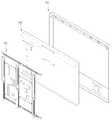
도 3은 본 발명에 따른 평판형 디스플레이 장치의 구조를 나타내는 결합 사시도이고, 도 4는 본 발명에 따른 평판형 디스플레이 장치의 구조를 나타내는 분해 사시도이다.Figure 3 is a combined perspective view showing the structure of a flat panel display device according to the present invention, Figure 4 is an exploded perspective view showing the structure of a flat panel display device according to the present invention.
도 3 및 도 4를 참조하면, 본 발명에 따른 평판형 디스플레이 장치는, 평판형 디스플레이 장치의 전면 외형을 이루는 전면 캐비넷(100)과, 상기 전면 캐비넷(100)의 후방에서 전방으로 결합되고 화상이 구현되는 디스플레이 모듈(200)과, 상기 디스플레이 모듈(200)의 일측에 결합되어 상기 디스플레이 모듈(200)이 고정되도록 하는 동시에 PCB 기판 등이 탑재되는 프레임 어셈블리(100)와, 평판형 디스플레이 장치의 후면 외형을 이루며 상기 디스플레이 모듈(200)을 보호하는 백 커버(미도시)가 포함되어 구성된다.Referring to FIGS. 3 and 4, the flat panel display apparatus according to the present invention includes a
상세히, 상기 전면 캐비넷(300)은 평판형 디스플레이 장치의 전면 외형을 이루는 동시에 상기 디스플레이 모듈(200)이 외부의 충격으로 인하여 파손되는 것을 방지하는 역할을 한다.In detail, the
한편, 상기 백 커버(미도시)는 외부의 충격으로부터 디스플레이 모듈(200)을 보호함과 아울러 후면으로 방출되는 전자파(Electro Magnetic Interference : 이하 "EMI"라 함)를 차단하는 역할을 한다.On the other hand, the back cover (not shown) serves to protect the
한편, 상기 디스플레이 모듈(200)은 상부기판과 하부기판이 합착되어 대략 장방형의 형상을 갖도록 구비된다. 상기 디스플레이 모듈(200)이 장방형의 형상을 갖는 이유는 사용자가 시청하기 바람직한 와이드 화면이 구현되도록 하기 위한 것 이다.On the other hand, the
한편, 상기 프레임 어셈블리(100)는 상기 디스플레이 모듈(200)의 후방에서 전방측으로 결합되어, 상기 전면 캐비넷(300)에 안착되는 디스플레이 모듈(200)의 고정 위치가 지지되도록 한다. 본 발명의 평판형 디스플레이 장치용 프레임은 상기 프레임 어셈블리(100)가 상하로 길이 조절이 가능하도록 구성되어, 다양한 크기의 디스플레이 모듈(200)에 결합 가능하도록 구성됨을 일 특징으로 한다.On the other hand, the
또한, 상기 프레임 어셈블리(100)의 일측에는 PCB 기판, 파워 보드, 메인 보드 등 상기 디스플레이 기기의 구동에 필요한 각종 부품들이 장착된다. 본 발명의 평판형 디스플레이 장치용 프레임은 상기 프레임 어셈블리(100)를 구성하는 수직 프레임 어셈블리(도 5의 200 참조)가 좌우로 이동 가능하도록 구성되어, 다양한 크기와 형태의 PCB 기판이 결합 가능하도록 구성됨을 일 특징으로 한다.In addition, various components necessary for driving the display device, such as a PCB board, a power board, and a main board, are mounted on one side of the
이하에서는 상기 프레임 어셈블리(100)에 대하여 보다 상세히 기술한다.Hereinafter, the
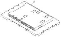
도 5는 본 발명에 따른 평판형 디스플레이 장치의 프레임 어셈블리의 구조를 나타내는 사시도이다.5 is a perspective view showing the structure of a frame assembly of a flat panel display device according to the present invention.
도 5를 참조하면, 본 발명에 따른 평판형 디스플레이 장치의 프레임 어셈블리(100)는, 상기 프레임 어셈블리(100)의 상단을 형성하며 길이 방향으로 가이드 홈이 형성되는 제 1 수평 프레임(110)과, 상기 프레임 어셈블리(100)의 하단을 형성하며 길이 방향으로 가이드 홈이 형성되는 제 2 수평 프레임(115)과, 상기 제 1 수평 프레임(110) 및 제 2 수평 프레임(115)과 결합되는 적어도 하나의 수직 프레 임 어셈블리(120)와, 상기 수직 프레임 어셈블리(120)에 결합되어 상기 프레임 어셈블리(100)에 장착되는 각종 부품의 고정 위치를 지지하는 지지 부재(150)가 포함되어 구성된다. 그리고, 상기 프레임 어셈블리(100)의 지지 부재(150) 위에 파워 보드(180) 및 메인 PCB 기판(190) 등이 결합된다.Referring to FIG. 5, the
상세히, 상기 제 1 수평 프레임(110)과 제 2 수평 프레임(115)은 각각 프레임 어셈블리(100)의 상단 및 하단을 구성한다. 그리고, 상기 제 1 수평 프레임(110) 및 제 2 수평 프레임(115)에 형성되는 가이드홈(도 6의 113 참조)에 상기 수직 프레임 어셈블리(120)가 적어도 하나 결합된다. 여기서, 상기 가이드홈(113)은 수평 프레임(110)(115)의 길이 방향으로 형성되어 있기 때문에, 사용자는 파워 보드(180) 및 메인 PCB 기판(190)의 크기 및 형상에 따라 상기 수직 프레임 어셈블리(120)의 결합 위치를 자유롭게 조정할 수 있다.In detail, the first
한편, 상기 수직 프레임 어셈블리(120)는, 수직 프레임 어셈블리(120)의 상단을 형성하는 제 1 수직 프레임(130)과, 일단이 상기 제 1 수직 프레임(130)에 수용되어 상기 제 1 수직 프레임(130)과 상호 인입되거나 인출되어 길이가 조절되도록 하는 제 2 수직 프레임(140)이 포함되어 구성된다. 상기와 같이 제 2 수직 프레임(140)이 제 1 수직 프레임(130) 내부로 인입되거나, 제 1 수직 프레임(130)으로부터 인출됨으로써 수직 프레임 어셈블리(120)의 전체적인 길이가 조절 가능하게 된다. 그리고, 상기와 같은 구성에 의하여 본 발명의 프레임 어셈블리(100)가 다양한 크기의 디스플레이 모듈(200)에 장착가능해지는 효과가 있다.The
그리고, 상기 수직 프레임 어셈블리(120)의 일단은 상기 제 1 수평 프레 임(110)과 결합되고, 타단은 제 2 수평 프레임(115)에 결합된다. 상술한 바와 같이, 상기 수직 프레임 어셈블리(120)는 제 1 수평 프레임(110)과 제 2 수평 프레임(115)에 형성되는 가이드홈(도 6의 113 참조)에 결합된다. 상기와 같은 구성에 의하여 다양한 크기와 형상의 PCB 기판이 결합 가능해지는 효과가 있다. 또한, 상기 수직 프레임 어셈블리(120)는 제 1 수평 프레임(110)과 제 2 수평 프레임(115)과 볼트 등의 별도의 결합 부재에 의하여 결합되기 때문에, 그 체결 및 해체가 자유로워지는 장점이 있다.One end of the
한편, 도면에는 상기 수직 프레임 어셈블리(120)는 세 개가 구비되는 것으로 도시되어 있으나, 본 발명의 사상은 이에 제한되지 아니하며, 상기 프레임 어셈블리(100)에 장착되는 부품의 개수 및 형상에 따라 수직 프레임 어셈블리(120)의 개수가 변경되는 것은 본 발명의 권리범위에 포함된다 할 것이다.Meanwhile, although three
한편, 상기 수직 프레임 어셈블리(120)에는 하나 이상의 지지 부재(150)가 결합된다. 상세히, 상기 제 1 수직 프레임(130)과 제 2 수직 프레임(140)에는 후술할 레일 형상의 지지부재 삽입홈 및 지지부재 결합홈이 형성되고, 상기 지지부재 삽입홈 및 지지부재 결합홈에 지지 부재(150)가 결합되기 때문에, 상기 지지 부재(150)의 결합 위치가 다양하게 변경 가능하다. 그리고, 상기와 같은 지지 부재(150) 결합 위치의 가변성에 의하여, 상기 지지 부재(150)에 다양한 형상 및 크기의 파워 보드(180) 및 PCB 기판(190)이 결합 가능해지는 효과가 있다.Meanwhile, at least one
이하에서는 상기 프레임 어셈블리(100)의 각 구성요소에 대하여 보다 상세히 기술한다.Hereinafter, each component of the
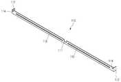
도 6은 본 발명에 따른 평판형 디스플레이 장치용 프레임의 제 1 수평 프레임의 구조를 나타내는 사시도이다.6 is a perspective view illustrating a structure of a first horizontal frame of a frame for a flat panel display device according to the present invention.
도 6을 참조하면, 상기 제 1 수평 프레임(110)은 긴 막대 형상의 프레임(111)과, 상기 프레임(111)의 양 단부에 형성되어 상기 디스플레이 모듈(200)에 결합되는 동시에 디스플레이 모듈(200)의 고정 위치를 지지하는 절곡부(112)와, 상기 프레임(111)의 대략 중심부에 프레임(111)의 길이 방향으로 형성되는 가이드홈(113)과, 상기 프레임(111)의 적어도 일측에 형성되어 후술할 수직 프레임 어셈블리(120)가 결합되도록 하는 하나 이상의 체결홀(114)이 포함되어 구성된다.Referring to FIG. 6, the first
상세히, 상기 제 1 수평 프레임(110)은 프레임 어셈블리(100)의 상단을 형성한다. 그리고, 상기 제 1 수평 프레임(110)은 강판 재질의 긴 막대 형상으로 형성되고, 대략 중심부에는 제 1 수평 프레임(110)의 길이 방향으로 가이드홈(113)이 형성된다. 그리고, 상기 가이드홈(113)에는 상기 수직 프레임 어셈블리(120)가 결합된다. 즉, 상기 가이드홈(113) 상측에 수직 프레임 어셈블리(120)의 체결홀(도 8의 144 참조)이 위치하고, 상기 가이드홈(113)과 체결홀(144)이 볼트/너트 등 별도의 체결 부재에 의하여 결합된다. 여기서, 상기 가이드홈(113)은 제 1 수평 프레임(111)의 길이 방향의 거의 전체에 대하여 형성되므로, 사용자가 원하는 위치에 자유롭게 수직 프레임 어셈블리(120)를 결합시킬 수 있다.In detail, the first
한편, 제 2 수평 프레임(115)은 상기 프레임 어셈블리(100)의 하단을 형성하고, 그 형상은 상기 제 1 수평 프레임(110)과 거의 동일하므로 상세한 기술은 생략 하도록 한다.On the other hand, the second
상기와 같이, 제 1 수평 프레임(110) 및 제 2 수평 프레임(115)에 길이 방향의 가이드 홈(113)이 형성되고, 수직 프레임 어셈블리(120)가 상기 가이드 홈(113)의 형성 위치에 자유롭게 결합 가능하기 때문에, 다양한 크기 및 형상의 PCB 기판이 장착 가능한 효과가 있다. 나아가서는, 프레임의 수평/수직 길이 및 상기 프레임에 구비되는 지지 부재의 고정 위치가 변경 가능하도록 구성되어, 프레임의 공용화가 가능해지는 효과가 있다.As described above, the
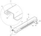
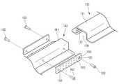
도 7은 본 발명에 따른 평판형 디스플레이 장치용 프레임의 제 1 수직 프레임의 구조를 나타내는 사시도이고, 도 8은 본 발명에 따른 평판형 디스플레이 장치용 프레임의 제 2 수직 프레임의 구조를 나타내는 사시도이고, 도 9는 도 7의 제 1 수직 프레임과 도 8의 제 2 수직 프레임의 결합 구조를 나타내는 사시도이다.7 is a perspective view showing the structure of a first vertical frame of a frame for a flat panel display device according to the present invention, FIG. 8 is a perspective view showing a structure of a second vertical frame of a frame for a flat panel display device according to the present invention; FIG. 9 is a perspective view illustrating a coupling structure of the first vertical frame of FIG. 7 and the second vertical frame of FIG. 8.
도 7을 참조하면, 상기 제 1 수직 프레임(130)은 본체를 이루는 프레임(131)과, 상기 프레임(131)의 일측에서 하방으로 돌출되도록 형성되어 상기 제 1 수직 프레임(130)을 지지하는 지지부(132)와, 상기 지지부(132)의 타측에 절곡 형성되어 상기 제 1 수평 프레임(110)과 결합되는 절곡부(133)가 포함되어 형성된다.Referring to FIG. 7, the first
상세히, 상기 제 1 수직 프레임(130)은 제 2 수직 프레임(140)과 결합하여 수직 프레임 어셈블리(120)를 형성한다. 그리고, 상기 수직 프레임 어셈블리(120)는 상술한 제 1 수평 프레임(110) 및 제 2 수평 프레임(115)에 결합되어 프레임 어셈블리(100)의 전체적인 골격을 형성한다. 물론, 상기 수직 프레임 어셈블리(120) 가 제품의 용도에 따라 하나 이상 구비되는 것은 자명하다 할 것이다. 그리고, 상기 프레임 어셈블리(100) 상에 PCB 기판(190)과 파워 보드(180) 등 디스플레이 장치의 각종 부품들이 결합된다.In detail, the first
여기서, 상기 프레임(131)에는 제 2 수직 프레임(140)이 수용되어 결합 가능하도록 대략 "┌┐" 형상의 수용부(138)가 형성된다. 즉, 상기 수용부(138) 내에 제 2 수직 프레임(140)이 수용되어 인입 및 인출됨으로써 상기 수직 프레임(120)의 길이가 조절가능하도록 형성된다.Here, the
또한, 상기 수용부(138)의 내부에는 상기 프레임(131)의 길이 방향으로 가이드 레일(137)이 하나 이상 형성된다. 그리고, 상기 가이드 레일(137)과 가이드 부재의 가이드 돌기(도 8에서 후술함)가 결합되어, 상기 제 1 수직 프레임(130)과 제 2 수직 프레임(140)의 결합이 견고하게 이루어지는 동시에, 제 2 수직 프레임(140)의 인입 및 인출이 가이드 된다.In addition, one or
한편, 상기 지지부(132)는 상기 프레임(131)의 일측에서 하방으로 돌출되도록 형성된다. 상기 지지부(132)는 상기 제 1 수직 프레임(130)을 지지하는 동시에, 상기 제 1 수직 프레임(130)이 제 1 수평 프레임(110)으로부터 일정 정도 이격되도록 하여, 상기 프레임 어셈블리(100)가 디스플레이 모듈(200)의 고정 위치를 지지하도록 한다.On the other hand, the
한편, 상기 지지부(132)의 일측에는 절곡부(133)가 형성되고, 상기 절곡부(133)에는 체결홀(미도시)이 형성된다. 상술한 바와 같이, 상기 체결홀과 제 1 수평 프레임(110)의 가이드홈(113)은 볼트/너트 등 별도의 체결 부재에 의하여 결 합된다.Meanwhile, a
또한, 상기 프레임(131)에는 지지 부재(150)가 삽입되는 지지부재 삽입홈(135)과, 상기 지지부재 삽입홈(135)에 삽입된 지지부재와 프레임(131)이 결합되도록 별도의 체결 부재가 관통되는 지지부재 결합홈(136)이 형성된다. 상기 제 1 수직 프레임(130)과 지지 부재(150)의 결합 관계는 도 13에서 후술한다.In addition, the
도 8을 참조하면, 상기 제 2 수직 프레임(140)은 대략 제 1 수직 프레임(130)과 유사한 형상으로 형성된다.Referring to FIG. 8, the second
상세히, 상기 제 2 수직 프레임(140)은 본체를 이루는 프레임(141)과, 상기 프레임(141)의 일측에서 하방으로 돌출되도록 형성되어 상기 제 2 수직 프레임(140)을 지지하는 지지부(142)와, 상기 지지부(142)의 타측에 절곡 형성되어 상기 제 2 수평 프레임(115)과 결합되는 절곡부(143)가 포함되어 형성된다. 또한, 상기 절곡부(143)에는 제 2 수평 프레임(115)의 결합홀과 결합되도록 하는 체결홀(144)가 더 형성된다. 또한, 상기 프레임(141)에는 지지 부재(150)가 삽입되는 지지부재 삽입홈(145)과, 상기 지지부재 삽입홈(145)에 삽입된 지지부재와 프레임(141)이 결합되도록 별도의 체결 부재가 관통되는 지지부재 결합홈(146)이 형성된다.In detail, the second
더욱 상세히, 상기 프레임(141)은 제 1 수직 프레임(130)의 수용부(138)에 결합된다. 이를 위하여, 상기 프레임(141)의 폭은 수용부(138)의 폭과 동일하거나 약간 작도록 형성되는 것이 바람직하다. 이와 같이, 제 2 수직 프레임(140)이 제 1 수직 프레임(130)에 수용되어 상호 인입 및 인출됨으로써, 수직 프레임 어셈블리(120)의 전체적인 길이가 조절된다.In more detail, the
한편, 상기 프레임(141)에서 지지부(142)가 형성되는 타측에는 가이드 부재(160)가 결합된다.On the other hand, the
상세히, 상기 가이드 부재(160)는 대략 장방형의 평판으로 형성되어 상기 프레임(141)의 적어도 일 측면에 결합된다. 그리고, 상기 가이드 부재(160)의 일 측에는 적어도 하나 이상의 가이드 돌기(161)가 형성된다. 상기 가이드 돌기(161)는 상술한 제 1 수직 프레임(130)의 가이드 레일(137)과 대응되도록 형성되어 상기 가이드 레일(137) 내부에 수용된다. 상기와 같이, 상기 가이드 레일(137)과 가이드 돌기(161)가 결합되어, 상기 제 1 수직 프레임(130)과 제 2 수직 프레임(140)의 결합이 견고하게 이루어지는 동시에, 제 2 수직 프레임(140)의 인입 및 인출이 가이드 된다. 한편, 상기 가이드 부재(160)는 제 1 체결 부재(162) 및 제 2 체결 부재(163)에 의하여 제 2 수직 프레임(140)에 결합된다. 상기 가이드 부재(160)와 제 2 수직 프레임(140)의 결합 관계는 이하에서 상세히 설명한다.In detail, the
도 9를 참조하면, 수직 프레임 어셈블리(120)의 조립 과정은 다음과 같다.9, the assembly process of the
먼저, 제 2 수직 프레임(140)과 가이드 부재(160)가 결합된다. 상세히, 상기 가이드 부재(160)에는 제 1 결합홀(164) 및 제 2 결합홀(165)이 형성된다. 그리고, 제 1 체결 부재(162) 및 제 2 체결 부재(163)가 상기 제 1 결합홀(164) 및 제 2 결합홀(165)을 관통하여 제 2 수직 프레임(140)에 체결된다.First, the second
여기서, 상기 제 1 결합홀(164)은 제 1 체결 부재(162)의 나사 부분만이 관통되도록 함몰 형성된다. 다시 말하면, 상기 제 1 체결 부재(162)의 머리 부분은 상기 가이드 부재(160)의 상측으로 일부분 돌출되도록 형성된다.Here, the
이에 반하여, 상기 제 2 결합홀(165)은 제 2 체결 부재(163)의 나사 부분과 더불어 머리 부분까지 수용되도록 함몰 형성된다. 다시 말하면, 제 2 결합홀(165)은 서로 직경이 다른 두 개의 원통이 단차지게 형성되어, 상기 제 2 체결 부재(163)의 머리 부분까지 수용되기 때문에, 제 2 체결 부재(163)의 머리 부분은 상기 가이드 부재(160)의 상측으로 돌출되지 않도록 형성된다.On the contrary, the
즉, 제 1 체결 부재(162)는 제 2 수직 프레임(140)과 가이드 부재(160)를 결합시키는 동시에, 제 2 수직 프레임(140)이 제 1 수직 프레임(130) 내부로 일정 정도 이상 인입되는 것을 방지하는 스토퍼(stopper)의 역할을 수행한다.That is, the
다음으로, 상기와 같이 가이드 부재(160)가 결합된 제 2 수직 프레임(140)이 제 1 수직 프레임(130)의 수용부(138)에 끼워진다. 여기서, 상기 가이드 부재(160)의 가이드 돌기(161)가 제 1 수직 프레임(130)의 가이드 레일(137)에 끼워짐으로써, 제 1 수직 프레임(130)과 제 2 수직 프레임(140) 간의 결합이 탈거되는 것이 방지되는 동시에, 제 2 수직 프레임(140)의 인입 및 인출이 가이드된다. 또한, 상술한 바와 같이, 제 1 체결 부재(162)에 의하여 제 2 수직 프레임(140)이 제 1 수직 프레임(130) 내부로 과도하게 인입되는 것이 방지된다.Next, the second
상기와 같은 구성에 의하여, 수직 프레임 어셈블리(120)의 길이가 조절가능함으로써, 다양한 크기의 디스플레이 모듈에 장착 가능한 평판형 디스플레이 장치 용 프레임이 제공된다. 또한, 프레임의 공용화가 가능해지며, 이를 통하여 제품 개발 시마다 프레임 제작을 위한 금형 개발이 필요하지 않게 되어, 금형 제작 비용 및 금형 제작 시간이 감소되는 효과가 있다.By the above configuration, the length of the
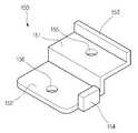
도 10은 본 발명에 따른 평판형 디스플레이 장치용 프레임의 지지 부재의 구조를 나타내는 사시도이다.10 is a perspective view showing the structure of a supporting member of a frame for a flat panel display device according to the present invention.
도 10을 참조하면, 본 발명의 지지 부재(150)는 서로 단차지도록 형성되는 제 1 평면부(151) 및 제 2 평면부(152)와, 상기 제 1 평면부(151)의 상측으로 돌출 형성되어 상기 수직 프레임 어셈블리(120)의 지지 부재 삽입홈(135)(145)에 끼워지는 이탈 방지부(153)와, 상기 제 2 평면부(152)의 상측으로 일정 정도 돌출되도록 형성되어 상기 지지 부재(150)에 안착되는 PCB 기판(190) 등의 고정 위치를 지지하는 위치 고정부(154)가 포함되어 구성된다.Referring to FIG. 10, the
또한, 상기 제 1 평면부(151)에는 수직 프레임 어셈블리(120)의 지지부재 결합홈(136)(146)과 결합되도록 하는 제 1 결합홀(155)이 형성된다. 그리고, 상기 제 2 평면부(152)에는 메인 보드(180), PCB 기판(190) 등이 결합되는 제 2 결합홀(156)이 형성된다.In addition, a
도 11은 수평 프레임, 수직 프레임 어셈블리 및 지지 부재의 결합 구조를 나타내는 사시도이다.11 is a perspective view illustrating a coupling structure of a horizontal frame, a vertical frame assembly, and a support member.
도 11을 참조하면, 제 1 수평 프레임(110)의 가이드홈(113)과 제 1 수직 프 레임의 체결홀(미도시), 그리고 제 2 수평 프레임(115)의 가이드홈(미도시)과 제 2 수직 프레임의 체결홀(144)은 별도의 체결 부재(171)에 의하여 결합된다.Referring to FIG. 11, the
여기서, 상기 가이드홈(113)은 수평 프레임(110)(115)의 길이 방향으로 길게 형성되어, 상기 가이드홈(113) 상의 어느 위치에나 수직 프레임 어셈블리(120)가 결합 가능하도록 형성된다. 바람직하게, 상기 수평 프레임(110)(115)과 수직 프레임 어셈블리(120)의 결합은 별도의 지그 등에 의하여 수행될 수 있다. 상기와 같은 방법을 통하여, 상기 수평 프레임(110)(115)과 수직 프레임 어셈블리(120)가 사용자가 원하는 결합 위치에 정확히 결합될 수 있다. 또한, 서로 다른 크기의 디스플레이 모듈이나 PCB 기판에 상기 프레임 어셈블리(100)를 적용하는 경우에도, 상기 지그를 조작하여 수평 프레임(110)(115)과 수직 프레임 어셈블리(120)의 결합 위치만을 조절하는 동작만으로 공용화가 가능해지는 장점이 있다.Here, the
한편, 상기 수직 프레임 어셈블리(120) 상에는 지지 부재(150)가 결합되는 과정은 다음과 같다.On the other hand, the process of coupling the
먼저, 상기 지지 부재(150)의 이탈 방지부(153)가 수직 프레임 어셈블리(120)의 지지 부재 삽입홈(135)(145)에 끼워진다. 상세히, 상기 지지 부재(150)는 일단 수직으로 세워져서, 상기 이탈 방지부(153)가 지지 부재 삽입홈(135)(145)과 평행한 상태에서 이탈 방지부(153)가 지지 부재 삽입홈(135)(145)에 끼워진다.First, the
다음으로, 상기 이탈 방지부(153)가 끼워진 상태에서 지지 부재(150)를 하방으로 가압하여, 상기 지지 부재(150)의 제 1 결합홀(155)이 지지 부재 결합홈(136)(146)에 맞닿도록 한다. 그리고, 상기 제 1 결합홀(155) 및 지지 부재 결합 홈(136)(146)에 별도의 볼트(173) 및 너트(174)가 체결되어 상기 지지 부재(150)가 수직 프레임 어셈블리(120)에 안정적으로 결합된다.Next, the
여기서, 상기 지지 부재 삽입홈(135)(145) 및 지지 부재 결합홈(136)(146)은 수직 프레임 어셈블리(120)의 길이 방향으로 길게 형성되기 때문에, 상기 수직 프레임 어셈블리(120)의 어느 위치에나 지지 부재(150)가 결합 가능하도록 형성된다. 상기와 같은 구성에 의하여 다양한 크기 및 형상의 PCB 기판, 메인 보드 등의 부품이 상기 프레임 어셈블리(100)에 결합 가능해지는 효과가 있다.Here, since the support
도 12는 본 발명에 따른 평판형 디스플레이의 프레임 어셈블리의 동작을 나타내는 사시도이다.12 is a perspective view showing the operation of the frame assembly of a flat panel display according to the present invention.
도 12를 참조하면, 본 발명에 따른 평판형 디스플레이의 프레임 어셈블리(100)는 상기 프레임 어셈블리(100)의 상단을 형성하는 제 1 수평 프레임(110)과, 프레임 어셈블리(100)의 하단을 형성하는 제 2 수평 프레임(115)이 형성되고, 상기 제 1 수평 프레임(110)과 제 2 수평 프레임(115) 사이에 하나 이상의 수직 프레임 어셈블리(120)가 결합된다. 그리고, 상기 수직 프레임 어셈블리(120)에는 지지 부재(150)가 형성되고, 상기 지지 부재(150)의 상측에 PCB 기판 및 파워 보드 등이 장착된다.Referring to FIG. 12, the
상세히, 상기 제 1 수평 프레임(110)과 제 2 수평 프레임(115)에는 길이 방향의 가이드홈(113)이 형성되고, 상기 가이드 홈(113)에 수직 프레임 어셈블리(120)의 상/하단이 각각 결합된다. 상기 수직 프레임 어셈블리(120)는 가이드 홈(113)이 형성되는 어느 위치에나 결합 가능하기 때문에, 상기 수직 프레임 어셈블리(120)의 위치를 조정함으로써 다양한 크기 및 형상의 PCB 기판이 결합될 수 있다.In detail, a
한편, 상기 수직 프레임 어셈블리(120)는 제 1 수직 프레임(130)과, 상기 제 1 수직 프레임(130)에 형성되는 수용부(138)에 수용되어 상기 제 1 수직 프레임(130)에 대하여 인입/인출이 가능하도록 형성되는 제 2 수직 프레임(140)이 포함되어 구성된다. 상기와 같이 제 2 수직 프레임(140)이 제 1 수직 프레임(130)에 대하여 인입 및 인출되어 수직 프레임 어셈블리(120)의 전체 길이가 조절 가능하도록 형성됨으로써, 다양한 크기의 디스플레이 모듈(200)에 공통적으로 적용 가능한 프레임 어셈블리(100)가 제공될 수 있다.On the other hand, the
한편, 상기 수직 프레임 어셈블리(120)에는 길이 방향의 지지 부재 삽입홈(135)(145) 및 지지 부재 결합홈(136)(146)이 형성되고, 지지 부재 삽입홈(135)(145) 및 지지 부재 결합홈(136)(146)이 형성되는 어느 위치에나 지지 부재(150)가 결합 가능하기 때문에, 다양한 크기 및 형상의 PCB 기판이 결합될 수 있다.On the other hand, the
본 발명에 따른 평판형 디스플레이 장치용 프레임에 의해서, 다양한 크기 및 형상의 PCB 기판 및 디스플레이 모듈이 장착 가능한 효과가 있다.By the frame for a flat panel display device according to the present invention, there is an effect that the PCB substrate and the display module of various sizes and shapes can be mounted.
또한, 프레임의 수평/수직 길이 및 상기 프레임에 구비되는 지지 부재의 고정 위치가 변경 가능하도록 구성되어, 프레임의 공용화가 가능해지는 장점이 있다.In addition, the horizontal / vertical length of the frame and the fixing position of the support member provided in the frame is configured to be changeable, there is an advantage that the frame can be shared.
또한, 상기와 같은 공용화를 통하여 제품 개발 시마다 프레임 제작을 위한 금형 개발이 필요하지 않게 되어, 금형 제작 비용 및 금형 제작 시간이 감소되는 효과가 있다.In addition, through the commonization as described above, the mold development for the production of the frame is not required every time the product is developed, thereby reducing the mold manufacturing cost and the mold manufacturing time.
또한, 프레임의 섀시 부분만이 강판으로 형성되기 때문에 강판 사용량이 절감되어 제조 원가가 감소되고, 제품의 중량이 감소되고, 이로 인하여 보관이 용이하고 물류 비용이 감소되는 효과가 있다.In addition, since only the chassis portion of the frame is formed of a steel sheet, the amount of steel sheet used is reduced, manufacturing cost is reduced, and the weight of the product is reduced, thereby facilitating storage and reducing logistics costs.
Claims (14)
Translated fromKoreanPriority Applications (5)
| Application Number | Priority Date | Filing Date | Title |
|---|---|---|---|
| KR1020060091588AKR100838879B1 (en) | 2006-09-21 | 2006-09-21 | Frames for Flat Panel Display Devices and Flat Panel Display Devices |
| US11/716,640US7515403B2 (en) | 2006-09-21 | 2007-03-12 | Flat panel display device and frame for the same |
| EP07290312AEP1909159B1 (en) | 2006-09-21 | 2007-03-13 | Flat panel display device and frame for the same |
| DE602007006121TDE602007006121D1 (en) | 2006-09-21 | 2007-03-13 | Flat screen and frame for it |
| CN2007100885927ACN101150942B (en) | 2006-09-21 | 2007-03-16 | Flat panel display device and frame for the same |
Applications Claiming Priority (1)
| Application Number | Priority Date | Filing Date | Title |
|---|---|---|---|
| KR1020060091588AKR100838879B1 (en) | 2006-09-21 | 2006-09-21 | Frames for Flat Panel Display Devices and Flat Panel Display Devices |
Publications (2)
| Publication Number | Publication Date |
|---|---|
| KR20080026708A KR20080026708A (en) | 2008-03-26 |
| KR100838879B1true KR100838879B1 (en) | 2008-06-16 |
Family
ID=39032271
Family Applications (1)
| Application Number | Title | Priority Date | Filing Date |
|---|---|---|---|
| KR1020060091588AExpired - Fee RelatedKR100838879B1 (en) | 2006-09-21 | 2006-09-21 | Frames for Flat Panel Display Devices and Flat Panel Display Devices |
Country Status (5)
| Country | Link |
|---|---|
| US (1) | US7515403B2 (en) |
| EP (1) | EP1909159B1 (en) |
| KR (1) | KR100838879B1 (en) |
| CN (1) | CN101150942B (en) |
| DE (1) | DE602007006121D1 (en) |
Families Citing this family (137)
| Publication number | Priority date | Publication date | Assignee | Title |
|---|---|---|---|---|
| JP5259110B2 (en)* | 2007-03-27 | 2013-08-07 | 三菱電機株式会社 | Display device |
| KR101335741B1 (en)* | 2007-06-04 | 2013-12-02 | 엘지전자 주식회사 | Display apparatus |
| KR101012587B1 (en)* | 2007-06-04 | 2011-02-01 | 엘지전자 주식회사 | Display device |
| KR100867858B1 (en)* | 2007-06-14 | 2008-11-07 | 웅진코웨이주식회사 | Filter frame |
| JP2009058670A (en)* | 2007-08-30 | 2009-03-19 | Hitachi Ltd | Plasma display device |
| JP4393546B2 (en)* | 2007-11-14 | 2010-01-06 | 株式会社東芝 | Display device |
| JP4956450B2 (en)* | 2008-01-16 | 2012-06-20 | 株式会社東芝 | Circuit board support structure for electronic equipment |
| JP5055171B2 (en) | 2008-03-10 | 2012-10-24 | 株式会社日立製作所 | Image display device |
| JP4342599B1 (en)* | 2008-08-29 | 2009-10-14 | 株式会社東芝 | Display device |
| KR20100043539A (en)* | 2008-10-20 | 2010-04-29 | 엘지전자 주식회사 | Display device |
| TWI362302B (en)* | 2009-10-21 | 2012-04-21 | Prime View Int Co Ltd | Method of manufacturing a base |
| KR101635124B1 (en)* | 2010-06-23 | 2016-06-30 | 김상용 | Auxiliary positive polar object of electroplating apparatus |
| USD637586S1 (en)* | 2010-09-15 | 2011-05-10 | Samsung Electronics Co., Ltd. | Wall mount for television |
| ES2576991T3 (en)* | 2010-10-28 | 2016-07-12 | Lg Electronics, Inc. | Display device |
| CA2826014C (en) | 2011-02-17 | 2016-01-12 | Millson Custom Solutions Inc. | Mounting apparatus for an audio/video system and related methods and systems |
| TWI415555B (en)* | 2011-05-24 | 2013-11-11 | Aten Int Co Ltd | Fixing device and rack using the same |
| US8801264B2 (en) | 2011-11-18 | 2014-08-12 | Shenzhen China Star Optoelectronics Technology Co., Ltd. | Back frame and backlight system of flat panel display device |
| US20130128155A1 (en)* | 2011-11-18 | 2013-05-23 | Shenzhen China Star Optoelectronics Technology Co., Ltd. | Flat Panel Display Device, Stereoscopic Display Device, and Plasma Display Device |
| US8913210B2 (en) | 2011-11-18 | 2014-12-16 | Shenzhen China Star Optoelectronics Technologies Co., Ltd. | Back frame and backlight system |
| CN102401332B (en)* | 2011-11-18 | 2014-12-31 | 深圳市华星光电技术有限公司 | Back frame, manufacturing method thereof and backlight system |
| CN102385820B (en)* | 2011-11-18 | 2015-06-10 | 深圳市华星光电技术有限公司 | Flat display device, stereo display device and plasma display device |
| US8783889B2 (en) | 2011-11-18 | 2014-07-22 | Shenzhen China Star Optoelectronics Technology Co., Ltd. | Back frame of flat panel display device, method for manufacturing back frame, and backlight system |
| US8988629B2 (en) | 2011-11-18 | 2015-03-24 | Shenzhen China Star Optoelectronics Technology Co., Ltd. | Flat panel display device, stereoscopic display device, and plasma display device |
| CN102392983B (en)* | 2011-11-18 | 2014-07-23 | 深圳市华星光电技术有限公司 | Back frame of panel display device, manufacturing method of back frame and backlight system |
| US8721099B2 (en) | 2011-11-18 | 2014-05-13 | Shenzhen China Star Optoelectronics Technology Co., Ltd. | Back frame and backlight system of flat panel display device |
| CN102401349B (en)* | 2011-11-18 | 2014-07-09 | 深圳市华星光电技术有限公司 | Method for manufacturing back frame and backlight system |
| US8879017B2 (en) | 2011-11-18 | 2014-11-04 | Shenzhen China Star Optoelectronics Technology Co., Ltd. | Flat panel display device and stereoscopic display device |
| US8787036B2 (en) | 2011-11-18 | 2014-07-22 | Shenzhen China Star Optoelectronics Technology Co., Ltd. | Back frame and backlight system |
| CN102401344B (en)* | 2011-11-18 | 2015-04-01 | 深圳市华星光电技术有限公司 | Back frame of flat panel display device and backlight system |
| CN102392999B (en) | 2011-11-18 | 2014-01-08 | 深圳市华星光电技术有限公司 | Back plate, backlight module utilizing same and liquid crystal display device |
| US8953115B2 (en) | 2011-11-18 | 2015-02-10 | Shenzhen China Star Optoelectronics Technology Co., Ltd. | Flat panel display device, stereoscopic display device, and plasma display device |
| CN102401342B (en)* | 2011-11-18 | 2013-07-17 | 深圳市华星光电技术有限公司 | Back frame of flat panel display device and backlight system |
| US8665390B2 (en)* | 2011-11-18 | 2014-03-04 | Shenzhen China Star Optoelectronics Technology Co., Ltd. | Flat panel display device, stereoscopic display device, and plasma display device |
| US9426906B2 (en) | 2011-11-18 | 2016-08-23 | Shenzhen China Star Optoelectronics Technology Co., Ltd. | Bracing piece, back frame, and backlight system of flat panel display device |
| US8891037B2 (en) | 2011-11-18 | 2014-11-18 | Shenzhen China Star Optoelectronics Technology Co., Ltd. | Flat panel display device, stereoscopic display device, and plasma display device |
| CN102376208B (en)* | 2011-11-18 | 2013-07-10 | 深圳市华星光电技术有限公司 | Flat-panel display device and stereoscopic display device |
| US8988630B2 (en) | 2011-11-18 | 2015-03-24 | Shenzhen China Star Optoelectronics Technology Co., Ltd. | Back frame and backlight system |
| CN102376222B (en)* | 2011-11-18 | 2013-09-04 | 深圳市华星光电技术有限公司 | Flat-panel display device, stereoscopic display device and plasma display device |
| US8611100B2 (en)* | 2011-11-18 | 2013-12-17 | Shenzhen China Star Optoelectronics Technology Co., Ltd. | Display device back panel with adjustable PCB mounting seat |
| CN102376213B (en)* | 2011-11-18 | 2013-07-10 | 深圳市华星光电技术有限公司 | Flat-panel display device, stereoscopic display device and plasma display device |
| CN102376221B (en)* | 2011-11-18 | 2015-04-29 | 深圳市华星光电技术有限公司 | Flat-panel display device, stereoscopic display device and plasma display device |
| CN102385821B (en)* | 2011-11-18 | 2014-10-15 | 深圳市华星光电技术有限公司 | Flat display device, stereo display device and plasma display device |
| CN102392986B (en)* | 2011-11-18 | 2013-10-02 | 深圳市华星光电技术有限公司 | Back frame and backlight system |
| CN102392987B (en)* | 2011-11-18 | 2013-07-17 | 深圳市华星光电技术有限公司 | Back frame and backlight system |
| CN102402915B (en)* | 2011-11-18 | 2013-06-05 | 深圳市华星光电技术有限公司 | Panel display device, stereo display device and plasma display device |
| CN102392992B (en)* | 2011-11-18 | 2013-07-17 | 深圳市华星光电技术有限公司 | Back frame, backlight system and panel liquid crystal display device |
| CN102402060B (en)* | 2011-11-18 | 2015-04-15 | 深圳市华星光电技术有限公司 | Flat panel display device, stereoscopic display device and plasma display device |
| CN102401337A (en)* | 2011-11-18 | 2012-04-04 | 深圳市华星光电技术有限公司 | Back frame, mold of back frame and bracket, manufacturing method of back frame and backlight system |
| CN102402059B (en)* | 2011-11-18 | 2014-04-09 | 深圳市华星光电技术有限公司 | Flat panel display device, stereoscopic display device and plasma display device |
| CN102374500B (en)* | 2011-11-18 | 2013-12-18 | 深圳市华星光电技术有限公司 | Back frame and backlight system |
| CN102401350B (en)* | 2011-11-18 | 2014-09-17 | 深圳市华星光电技术有限公司 | Back frame of flat panel display devic and backlight system |
| US20130128156A1 (en)* | 2011-11-18 | 2013-05-23 | Shenzhen China Star Optoelectronics Technology Co. Ltd. | Flat Panel Display Device, Stereoscopic Display Device, and Plasma Display Device |
| CN102376220B (en)* | 2011-11-18 | 2013-10-16 | 深圳市华星光电技术有限公司 | Flat-panel display device, stereoscopic display device and plasma display device |
| CN102402053B (en)* | 2011-11-18 | 2015-04-15 | 深圳市华星光电技术有限公司 | Panel display device, stereo display device and plasma display device |
| US8727602B2 (en) | 2011-11-18 | 2014-05-20 | Shenzhen China Star Optoelectronics Technology Co., Ltd. | Flat panel display device, stereoscopic display device, and plasma display device |
| US8994893B2 (en) | 2011-11-18 | 2015-03-31 | Shenzhen China Star Optoelectronics Technology Co., Ltd. | Flat panel display device, stereoscopic display device, and plasma display device |
| CN102385819B (en)* | 2011-11-18 | 2015-04-15 | 深圳市华星光电技术有限公司 | Flat display device, stereo display device and plasma display device |
| US8896785B2 (en) | 2011-11-18 | 2014-11-25 | Shenzhen China Star Optoelectronics Technology Co., Ltd. | Flat panel display device, stereoscopic display device, and plasma display device |
| CN102434859B (en)* | 2011-11-18 | 2013-12-18 | 深圳市华星光电技术有限公司 | Back frame and back light system |
| US8678604B2 (en) | 2011-11-18 | 2014-03-25 | Shenzhen China Star Optoelectronics Technology Co., Ltd. | Mold for back frame and bracing piece, method for manufacturing back frame, and backlight system |
| CN102402052B (en)* | 2011-11-18 | 2014-05-28 | 深圳市华星光电技术有限公司 | Flat panel display device, stereoscopic display device and plasma display device |
| CN102401335B (en)* | 2011-11-18 | 2013-04-17 | 深圳市华星光电技术有限公司 | Back frame of flat panel display device and backlight system |
| CN102402048A (en)* | 2011-11-18 | 2012-04-04 | 深圳市华星光电技术有限公司 | Panel display device, stereo display device and plasma display device |
| CN102402056B (en)* | 2011-11-18 | 2014-04-02 | 深圳市华星光电技术有限公司 | Flat-plate display device and three-dimensional display device |
| CN102425742A (en)* | 2011-11-18 | 2012-04-25 | 深圳市华星光电技术有限公司 | Backlight system |
| CN102394032B (en)* | 2011-11-18 | 2014-04-16 | 深圳市华星光电技术有限公司 | Panel display device and stereo display device |
| US9220173B2 (en) | 2011-11-18 | 2015-12-22 | Shenzhen China Star Optoelectronics Technology Co., Ltd. | Back frame of flat panel display device, method for manufacturing back frame, and backlight system |
| US8777475B2 (en) | 2011-11-18 | 2014-07-15 | Shenzhen China Star Optoelectronics Technology Co., Ltd. | Back frame, method for manufacturing back frame, and backlight system |
| CN102410507B (en)* | 2011-11-18 | 2014-07-09 | 深圳市华星光电技术有限公司 | Back frame and backlight system of panel display device |
| US8944665B2 (en) | 2011-11-18 | 2015-02-03 | Shenzhen China Star Optoelectronics Technology Co., Ltd. | Back frame, method for manufacturing back frame, and backlight system |
| US8724045B2 (en) | 2011-11-18 | 2014-05-13 | Shenzhen China Star Optoelectronics Technology Co., Ltd. | Flat panel display device and stereoscopic display device |
| CN102376224B (en)* | 2011-11-18 | 2015-06-10 | 深圳市华星光电技术有限公司 | Flat-panel display device, stereoscopic display device and plasma display device |
| CN102402046B (en)* | 2011-11-18 | 2014-05-28 | 深圳市华星光电技术有限公司 | Panel display device, stereo display device and plasma display device |
| US8823896B2 (en) | 2011-11-18 | 2014-09-02 | Shenzhen China Star Optoelectronics Technology Co., Ltd. | Flat panel display device, stereoscopic display device, and plasma display device |
| US8905616B2 (en) | 2011-11-18 | 2014-12-09 | Shenzhen China Star Optoelectronics Technology Co., Ltd. | Back frame and backlight system of flat panel display device |
| CN102374501B (en)* | 2011-11-18 | 2013-04-17 | 深圳市华星光电技术有限公司 | Back frame and backlight system |
| CN102401340B (en)* | 2011-11-18 | 2013-06-19 | 深圳市华星光电技术有限公司 | Back frame and backlight system |
| CN102402047B (en)* | 2011-11-18 | 2014-06-11 | 深圳市华星光电技术有限公司 | Flat panel display device, stereoscopic display device and plasma display device |
| CN102410506B (en)* | 2011-11-18 | 2014-10-15 | 深圳市华星光电技术有限公司 | Dies of back frame and bracket, manufacture method of back frame, and backlight system |
| CN102402916B (en)* | 2011-11-18 | 2013-09-04 | 深圳市华星光电技术有限公司 | Panel display device, stereo display device and plasma display device |
| CN102376215B (en)* | 2011-11-18 | 2015-04-15 | 深圳市华星光电技术有限公司 | Flat-panel display device, stereoscopic display device and plasma display device |
| CN102376209B (en)* | 2011-11-18 | 2014-04-16 | 深圳市华星光电技术有限公司 | Flat-panel display device and stereoscopic display device |
| US8872995B2 (en) | 2011-11-18 | 2014-10-28 | Shenzhen China Star Optoelectronics Technology Co., Ltd. | Flat panel display device, stereoscopic display device, and plasma display device |
| CN102376225B (en)* | 2011-11-18 | 2013-09-04 | 深圳市华星光电技术有限公司 | Flat-panel display device, stereoscopic display device and plasma display device |
| CN102401336B (en)* | 2011-11-18 | 2014-06-18 | 深圳市华星光电技术有限公司 | Back frame of flat panel display device, manufacturing method thereof and backlight system |
| US20130128154A1 (en)* | 2011-11-18 | 2013-05-23 | Shenzhen China Star Optoelectronics Technology Co. Ltd. | Flat Panel Display Device, Stereoscopic Display Device, and Plasma Display Device |
| CN102376212B (en)* | 2011-11-18 | 2014-12-31 | 深圳市华星光电技术有限公司 | Flat-panel display device, stereoscopic display device and plasma display device |
| CN102410509B (en)* | 2011-11-18 | 2014-07-30 | 深圳市华星光电技术有限公司 | Back panel and backlight module |
| CN102401345B (en)* | 2011-11-18 | 2014-12-31 | 深圳市华星光电技术有限公司 | Back frame, mold thereof, manufacturing method thereof and backlight system |
| CN102384409B (en)* | 2011-11-18 | 2016-03-23 | 深圳市华星光电技术有限公司 | Back light system |
| CN102376228B (en)* | 2011-11-18 | 2014-10-15 | 深圳市华星光电技术有限公司 | Flat-panel display device, stereoscopic display device and plasma display device |
| CN102494266B (en)* | 2011-11-18 | 2014-08-20 | 深圳市华星光电技术有限公司 | Backlight system |
| CN102376210B (en)* | 2011-11-18 | 2014-06-11 | 深圳市华星光电技术有限公司 | Flat-panel display device and stereoscopic display device |
| CN102592519B (en)* | 2011-11-18 | 2014-09-17 | 深圳市华星光电技术有限公司 | Flat panel display device and stereoscopic display device |
| CN102402913B (en)* | 2011-11-18 | 2013-10-16 | 深圳市华星光电技术有限公司 | Flat panel display device, stereoscopic display device and plasma display device |
| CN102401334B (en)* | 2011-11-18 | 2013-11-27 | 深圳市华星光电技术有限公司 | Back frame of flat panel display device and backlight system |
| US8913209B2 (en)* | 2011-11-18 | 2014-12-16 | Shenzhen China Star Optoelectronics Technology Co., Ltd. | Flat panel display device, stereoscopic display device, and plasma display device |
| US8947611B2 (en)* | 2011-11-18 | 2015-02-03 | Shenzhen China Star Optoelectronics Technology Co., Ltd. | Flat panel display device, stereoscopic display device, and plasma display device |
| CN102401343B (en)* | 2011-11-18 | 2014-06-11 | 深圳市华星光电技术有限公司 | Back frame and backlight system |
| CN102401346B (en)* | 2011-11-18 | 2014-01-01 | 深圳市华星光电技术有限公司 | Die for back frame and bracket, manufacturing method for back frame and backlight system |
| US8896780B2 (en) | 2011-11-18 | 2014-11-25 | Shenzhen China Star Optoelectronics Technology Co., Ltd. | Back frame and backlight system |
| CN102402057B (en)* | 2011-11-18 | 2015-03-11 | 深圳市华星光电技术有限公司 | Panel display device, stereo display device and plasma display device |
| CN102402917B (en)* | 2011-11-18 | 2014-04-09 | 深圳市华星光电技术有限公司 | Panel display device, stereo display device and plasma display device |
| CN102402049B (en)* | 2011-11-18 | 2014-06-11 | 深圳市华星光电技术有限公司 | Panel display device, stereo display device and plasma display device |
| CN102376218B (en)* | 2011-11-18 | 2014-07-09 | 深圳市华星光电技术有限公司 | Flat-panel display device and stereoscopic display device |
| CN102376226B (en)* | 2011-11-18 | 2015-02-11 | 深圳市华星光电技术有限公司 | Flat-panel display device, stereoscopic display device and plasma display device |
| CN102402054B (en)* | 2011-11-18 | 2013-07-10 | 深圳市华星光电技术有限公司 | Flat-plate display device, three-dimensional display device and plasma display device |
| US9134557B2 (en) | 2011-11-18 | 2015-09-15 | Shenzhen China Star Optoelectronics Technology Co., Ltd. | Back frame and backlight system of flat panel display device |
| CN102376216B (en)* | 2011-11-18 | 2014-10-15 | 深圳市华星光电技术有限公司 | Flat-panel display device and stereoscopic display device |
| US8953114B2 (en) | 2011-11-18 | 2015-02-10 | Shenzhen China Star Optoelectronics Technology Co., Ltd. | Back frame and backlight system |
| CN102376229B (en)* | 2011-11-18 | 2013-09-04 | 深圳市华星光电技术有限公司 | Flat-panel display device and stereoscopic display device |
| US8976312B2 (en) | 2011-11-18 | 2015-03-10 | Shenzhen China Star Optoeletronics Technology Co., Ltd. | Flat panel display device and stereoscopic display device |
| CN102376223B (en)* | 2011-11-18 | 2014-12-31 | 深圳市华星光电技术有限公司 | Flat-panel display device, stereoscopic display device and plasma display device |
| CN102494307B (en)* | 2011-11-18 | 2014-04-16 | 深圳市华星光电技术有限公司 | Support, back frame and backlight system of flat panel display device |
| US8789958B2 (en) | 2011-11-18 | 2014-07-29 | Shenzhen China Star Optoelectronics Technology Co., Ltd. | Flat panel display device, stereoscopic display device, and plasma display device |
| CN102392994B (en)* | 2011-11-18 | 2014-10-15 | 深圳市华星光电技术有限公司 | Back frame of panel display device, backlight system and panel liquid crystal display device |
| WO2013071661A1 (en)* | 2011-11-18 | 2013-05-23 | 深圳市华星光电技术有限公司 | Backlight module, back board and liquid crystal display device |
| US8947612B2 (en) | 2011-11-18 | 2015-02-03 | Shenzhen China Star Optoelectronics Technology Co., Ltd. | Flat panel display device and stereoscopic display device |
| CN102489603A (en)* | 2011-11-25 | 2012-06-13 | 深圳市华星光电技术有限公司 | Stamping die of splicing back plate, and processing method of splicing back plate |
| CN102606975B (en)* | 2012-03-26 | 2013-11-06 | 深圳市华星光电技术有限公司 | Backlight module and LCD (liquid crystal display) |
| US8749728B2 (en)* | 2012-03-30 | 2014-06-10 | Shenzhen China Star Optoelectronics Technology Co., Ltd. | Backplane and LCD device comprising backplane |
| CN102645766A (en)* | 2012-04-28 | 2012-08-22 | 深圳市华星光电技术有限公司 | Liquid crystal display device and frame for same |
| WO2014046026A1 (en)* | 2012-09-20 | 2014-03-27 | シャープ株式会社 | Display device and television receiver device |
| HK1216354A1 (en)* | 2013-02-12 | 2016-11-04 | The Impresario Company Limited | A frame for an object |
| JP2015200710A (en)* | 2014-04-04 | 2015-11-12 | パナソニック株式会社 | Display device mounting metal fitting and display device mounting fixture |
| TW201600910A (en)* | 2014-06-25 | 2016-01-01 | 立寶光電股份有限公司 | Assembling type support structure of backlight module |
| TW201600909A (en)* | 2014-06-25 | 2016-01-01 | 立寶光電股份有限公司 | Assembling type support structure of backlight module |
| JP6405227B2 (en)* | 2014-12-19 | 2018-10-17 | 古野電気株式会社 | Display device and display device manufacturing method |
| TWI551924B (en)* | 2015-01-19 | 2016-10-01 | Radiant Opto Electronics Corp | Frame assembly |
| KR101554734B1 (en)* | 2015-03-25 | 2015-09-21 | 주식회사 하이웰 | A frame and a cabinet thereof |
| CN104776979B (en)* | 2015-05-04 | 2018-05-18 | 合肥鑫晟光电科技有限公司 | A kind of panel detection board |
| KR101684599B1 (en)* | 2015-05-07 | 2016-12-09 | 희성전자 주식회사 | Paper for back cover of display device |
| GB2549990B (en)* | 2016-05-06 | 2021-10-20 | Urben Tech Limited | A Display Unit |
| CN113066379B (en)* | 2017-06-29 | 2023-01-24 | 群创光电股份有限公司 | Display device |
| JP7462137B2 (en)* | 2019-09-11 | 2024-04-05 | パナソニックIpマネジメント株式会社 | Electronics |
| GB2597752B (en) | 2020-08-03 | 2025-02-12 | Urben Tech Holdings Ltd | A display unit |
| CN111988948B (en)* | 2020-08-10 | 2021-10-26 | 泰州市博泰电子有限公司 | Combined mobile communication circuit board |
Citations (4)
| Publication number | Priority date | Publication date | Assignee | Title |
|---|---|---|---|---|
| JP2000010082A (en) | 1998-06-23 | 2000-01-14 | Sharp Corp | Mounting structure of liquid crystal display element and liquid crystal display device |
| JP2001033761A (en) | 1999-07-15 | 2001-02-09 | Nec Yonezawa Ltd | Liquid module mounting structure |
| KR20050073213A (en)* | 2004-01-09 | 2005-07-13 | 현대 이미지퀘스트(주) | Assembling structure of lcd module and main frame |
| KR20060098882A (en)* | 2005-03-08 | 2006-09-19 | 삼성전자주식회사 | Display device |
Family Cites Families (11)
| Publication number | Priority date | Publication date | Assignee | Title |
|---|---|---|---|---|
| IT230672Y1 (en)* | 1993-10-26 | 1999-06-09 | Cms Costr Meccan Sestesi Srl | CABINET STRUCTURE, FOR ELECTRIC OR ELECTRONIC EQUIPMENT, WITH VARIABLE DIMENSIONS |
| US5768096A (en)* | 1996-10-30 | 1998-06-16 | Hewlett-Packard Company | Portable computer with movable display panels forming a concatenated display screen in response to opening the computer |
| JP3043710B2 (en)* | 1997-08-04 | 2000-05-22 | キヤノン株式会社 | A support structure for supporting a panel, a panel device having a panel and a support structure for supporting the panel, and an image forming apparatus using the panel device |
| CN1142536C (en)* | 1998-10-30 | 2004-03-17 | 松下电器产业株式会社 | Display device with plasma display panel |
| CN2547232Y (en)* | 2002-07-03 | 2003-04-30 | 竑豫科技股份有限公司 | Activity computer advertising display stand structure |
| EP1742468A3 (en)* | 2002-08-02 | 2008-12-31 | Sony Corporation | Flat type image display apparatus |
| US20040142766A1 (en)* | 2003-01-17 | 2004-07-22 | Chris Savarese | Apparatuses, methods and systems relating to findable golf balls |
| US7529082B2 (en)* | 2004-04-16 | 2009-05-05 | Funai Electric Co., Ltd. | Plasma television, flat panel display fixing structure, flat panel television, and method of assembling flat panel television |
| KR20060027124A (en)* | 2004-09-22 | 2006-03-27 | 삼성에스디아이 주식회사 | Plasma display module having a filter film and plasma display device comprising the same |
| KR100670252B1 (en)* | 2004-12-17 | 2007-01-16 | 삼성에스디아이 주식회사 | Chassis base assembly, method for manufacturing same, and plasma display assembly using the same |
| US20070258196A1 (en)* | 2006-05-05 | 2007-11-08 | Designer Av Equipment | Flat panel television mounting assembly, and method |
- 2006
- 2006-09-21KRKR1020060091588Apatent/KR100838879B1/ennot_activeExpired - Fee Related
- 2007
- 2007-03-12USUS11/716,640patent/US7515403B2/enactiveActive
- 2007-03-13DEDE602007006121Tpatent/DE602007006121D1/enactiveActive
- 2007-03-13EPEP07290312Apatent/EP1909159B1/ennot_activeNot-in-force
- 2007-03-16CNCN2007100885927Apatent/CN101150942B/ennot_activeExpired - Fee Related
Patent Citations (4)
| Publication number | Priority date | Publication date | Assignee | Title |
|---|---|---|---|---|
| JP2000010082A (en) | 1998-06-23 | 2000-01-14 | Sharp Corp | Mounting structure of liquid crystal display element and liquid crystal display device |
| JP2001033761A (en) | 1999-07-15 | 2001-02-09 | Nec Yonezawa Ltd | Liquid module mounting structure |
| KR20050073213A (en)* | 2004-01-09 | 2005-07-13 | 현대 이미지퀘스트(주) | Assembling structure of lcd module and main frame |
| KR20060098882A (en)* | 2005-03-08 | 2006-09-19 | 삼성전자주식회사 | Display device |
Also Published As
| Publication number | Publication date |
|---|---|
| EP1909159A1 (en) | 2008-04-09 |
| US7515403B2 (en) | 2009-04-07 |
| DE602007006121D1 (en) | 2010-06-10 |
| EP1909159B1 (en) | 2010-04-28 |
| CN101150942A (en) | 2008-03-26 |
| CN101150942B (en) | 2010-12-08 |
| KR20080026708A (en) | 2008-03-26 |
| US20080074349A1 (en) | 2008-03-27 |
Similar Documents
| Publication | Publication Date | Title |
|---|---|---|
| KR100838879B1 (en) | Frames for Flat Panel Display Devices and Flat Panel Display Devices | |
| US7924366B2 (en) | Image displaying apparatus | |
| JP4342599B1 (en) | Display device | |
| US7742288B2 (en) | Display device | |
| US8665391B2 (en) | Liquid crystal display device and its case | |
| US20090121096A1 (en) | Display Device | |
| US20060146223A1 (en) | Liquid crystal television and liquid crystal display apparatus | |
| KR100633074B1 (en) | Display device | |
| US7999883B2 (en) | Display | |
| KR100852525B1 (en) | Display module and supporting apparatus for display module | |
| US20060059751A1 (en) | Combination frame for fixing display panel module | |
| CN210716642U (en) | Limiting structure and display screen | |
| KR20040009338A (en) | Monitor | |
| US20250185199A1 (en) | Display device | |
| US20050067550A1 (en) | Plasma display device and chassis base thereof | |
| US9426906B2 (en) | Bracing piece, back frame, and backlight system of flat panel display device | |
| CN101778231A (en) | Display device and assembling method thereof | |
| KR20060009515A (en) | Panel mounting structure of display device | |
| KR20110007552A (en) | Display device | |
| KR20060098886A (en) | Display device |
Legal Events
| Date | Code | Title | Description |
|---|---|---|---|
| A201 | Request for examination | ||
| PA0109 | Patent application | St.27 status event code:A-0-1-A10-A12-nap-PA0109 | |
| PA0201 | Request for examination | St.27 status event code:A-1-2-D10-D11-exm-PA0201 | |
| D13-X000 | Search requested | St.27 status event code:A-1-2-D10-D13-srh-X000 | |
| D14-X000 | Search report completed | St.27 status event code:A-1-2-D10-D14-srh-X000 | |
| E902 | Notification of reason for refusal | ||
| PE0902 | Notice of grounds for rejection | St.27 status event code:A-1-2-D10-D21-exm-PE0902 | |
| P11-X000 | Amendment of application requested | St.27 status event code:A-2-2-P10-P11-nap-X000 | |
| P13-X000 | Application amended | St.27 status event code:A-2-2-P10-P13-nap-X000 | |
| E701 | Decision to grant or registration of patent right | ||
| PE0701 | Decision of registration | St.27 status event code:A-1-2-D10-D22-exm-PE0701 | |
| PG1501 | Laying open of application | St.27 status event code:A-1-1-Q10-Q12-nap-PG1501 | |
| GRNT | Written decision to grant | ||
| PR0701 | Registration of establishment | St.27 status event code:A-2-4-F10-F11-exm-PR0701 | |
| PR1002 | Payment of registration fee | St.27 status event code:A-2-2-U10-U11-oth-PR1002 Fee payment year number:1 | |
| PG1601 | Publication of registration | St.27 status event code:A-4-4-Q10-Q13-nap-PG1601 | |
| PN2301 | Change of applicant | St.27 status event code:A-5-5-R10-R13-asn-PN2301 St.27 status event code:A-5-5-R10-R11-asn-PN2301 | |
| R18-X000 | Changes to party contact information recorded | St.27 status event code:A-5-5-R10-R18-oth-X000 | |
| R18-X000 | Changes to party contact information recorded | St.27 status event code:A-5-5-R10-R18-oth-X000 | |
| PR1001 | Payment of annual fee | St.27 status event code:A-4-4-U10-U11-oth-PR1001 Fee payment year number:4 | |
| PR1001 | Payment of annual fee | St.27 status event code:A-4-4-U10-U11-oth-PR1001 Fee payment year number:5 | |
| FPAY | Annual fee payment | Payment date:20130514 Year of fee payment:6 | |
| PR1001 | Payment of annual fee | St.27 status event code:A-4-4-U10-U11-oth-PR1001 Fee payment year number:6 | |
| FPAY | Annual fee payment | Payment date:20140523 Year of fee payment:7 | |
| PR1001 | Payment of annual fee | St.27 status event code:A-4-4-U10-U11-oth-PR1001 Fee payment year number:7 | |
| FPAY | Annual fee payment | Payment date:20150522 Year of fee payment:8 | |
| PN2301 | Change of applicant | St.27 status event code:A-5-5-R10-R13-asn-PN2301 St.27 status event code:A-5-5-R10-R11-asn-PN2301 | |
| PR1001 | Payment of annual fee | St.27 status event code:A-4-4-U10-U11-oth-PR1001 Fee payment year number:8 | |
| FPAY | Annual fee payment | Payment date:20160524 Year of fee payment:9 | |
| PR1001 | Payment of annual fee | St.27 status event code:A-4-4-U10-U11-oth-PR1001 Fee payment year number:9 | |
| FPAY | Annual fee payment | Payment date:20170524 Year of fee payment:10 | |
| PR1001 | Payment of annual fee | St.27 status event code:A-4-4-U10-U11-oth-PR1001 Fee payment year number:10 | |
| FPAY | Annual fee payment | Payment date:20180524 Year of fee payment:11 | |
| PR1001 | Payment of annual fee | St.27 status event code:A-4-4-U10-U11-oth-PR1001 Fee payment year number:11 | |
| PR1001 | Payment of annual fee | St.27 status event code:A-4-4-U10-U11-oth-PR1001 Fee payment year number:12 | |
| PR1001 | Payment of annual fee | St.27 status event code:A-4-4-U10-U11-oth-PR1001 Fee payment year number:13 | |
| PN2301 | Change of applicant | St.27 status event code:A-5-5-R10-R13-asn-PN2301 St.27 status event code:A-5-5-R10-R11-asn-PN2301 | |
| PC1903 | Unpaid annual fee | St.27 status event code:A-4-4-U10-U13-oth-PC1903 Not in force date:20210611 Payment event data comment text:Termination Category : DEFAULT_OF_REGISTRATION_FEE | |
| PC1903 | Unpaid annual fee | St.27 status event code:N-4-6-H10-H13-oth-PC1903 Ip right cessation event data comment text:Termination Category : DEFAULT_OF_REGISTRATION_FEE Not in force date:20210611 |