KR100836321B1 - Car monitor device - Google Patents
Car monitor deviceDownload PDFInfo
- Publication number
- KR100836321B1 KR100836321B1KR1020060106087AKR20060106087AKR100836321B1KR 100836321 B1KR100836321 B1KR 100836321B1KR 1020060106087 AKR1020060106087 AKR 1020060106087AKR 20060106087 AKR20060106087 AKR 20060106087AKR 100836321 B1KR100836321 B1KR 100836321B1
- Authority
- KR
- South Korea
- Prior art keywords
- lcd monitor
- monitor
- lcd
- case
- shelf
- Prior art date
- Legal status (The legal status is an assumption and is not a legal conclusion. Google has not performed a legal analysis and makes no representation as to the accuracy of the status listed.)
- Expired - Fee Related
Links
Images


Classifications
- B—PERFORMING OPERATIONS; TRANSPORTING
- B60—VEHICLES IN GENERAL
- B60R—VEHICLES, VEHICLE FITTINGS, OR VEHICLE PARTS, NOT OTHERWISE PROVIDED FOR
- B60R11/00—Arrangements for holding or mounting articles, not otherwise provided for
- B60R11/02—Arrangements for holding or mounting articles, not otherwise provided for for radio sets, television sets, telephones, or the like; Arrangement of controls thereof
- B60R11/0229—Arrangements for holding or mounting articles, not otherwise provided for for radio sets, television sets, telephones, or the like; Arrangement of controls thereof for displays, e.g. cathodic tubes
- B60R11/0235—Arrangements for holding or mounting articles, not otherwise provided for for radio sets, television sets, telephones, or the like; Arrangement of controls thereof for displays, e.g. cathodic tubes of flat type, e.g. LCD
- B—PERFORMING OPERATIONS; TRANSPORTING
- B60—VEHICLES IN GENERAL
- B60R—VEHICLES, VEHICLE FITTINGS, OR VEHICLE PARTS, NOT OTHERWISE PROVIDED FOR
- B60R11/00—Arrangements for holding or mounting articles, not otherwise provided for
- B60R2011/0001—Arrangements for holding or mounting articles, not otherwise provided for characterised by position
- B60R2011/0003—Arrangements for holding or mounting articles, not otherwise provided for characterised by position inside the vehicle
- B60R2011/0028—Ceiling, e.g. roof rails
- B—PERFORMING OPERATIONS; TRANSPORTING
- B60—VEHICLES IN GENERAL
- B60R—VEHICLES, VEHICLE FITTINGS, OR VEHICLE PARTS, NOT OTHERWISE PROVIDED FOR
- B60R11/00—Arrangements for holding or mounting articles, not otherwise provided for
- B60R2011/0042—Arrangements for holding or mounting articles, not otherwise provided for characterised by mounting means
- B60R2011/008—Adjustable or movable supports
- B60R2011/0092—Adjustable or movable supports with motorization
- Y—GENERAL TAGGING OF NEW TECHNOLOGICAL DEVELOPMENTS; GENERAL TAGGING OF CROSS-SECTIONAL TECHNOLOGIES SPANNING OVER SEVERAL SECTIONS OF THE IPC; TECHNICAL SUBJECTS COVERED BY FORMER USPC CROSS-REFERENCE ART COLLECTIONS [XRACs] AND DIGESTS
- Y10—TECHNICAL SUBJECTS COVERED BY FORMER USPC
- Y10S—TECHNICAL SUBJECTS COVERED BY FORMER USPC CROSS-REFERENCE ART COLLECTIONS [XRACs] AND DIGESTS
- Y10S345/00—Computer graphics processing and selective visual display systems
- Y10S345/905—Display device with housing structure
Landscapes
- Engineering & Computer Science (AREA)
- Mechanical Engineering (AREA)
- Fittings On The Vehicle Exterior For Carrying Loads, And Devices For Holding Or Mounting Articles (AREA)
- Devices For Indicating Variable Information By Combining Individual Elements (AREA)
Abstract
Translated fromKoreanDescription
Translated fromKorean도 1과 도 2는 종래기술에 따른 차량용 LCD 모니터 장치의 예를 도시한 도면으로서, 도 1은 LCD 모니터의 열린 상태를, 도 2는 LCD 모니터의 닫힌 상태를 나타낸 도면,1 and 2 is a view showing an example of a vehicle LCD monitor device according to the prior art, Figure 1 is an open state of the LCD monitor, Figure 2 is a view showing a closed state of the LCD monitor,
도 3은 본 발명에 따른 차량용 모니터 장치의 설치위치를 보여주기 위한 설치상태도,3 is an installation state diagram for showing the installation position of the vehicle monitor device according to the invention,
도 4와 도 5는 본 발명에 따른 모니터 장치의 구성요소가 선반 내부에 설치된 상태를 도시한 도면으로서, 도 4는 LCD 모니터의 완전 수납상태를, 도 5는 LCD 모니터의 완전 전개상태를 나타낸 도면,4 and 5 are views illustrating a state in which the components of the monitor device according to the present invention are installed in a shelf. FIG. 4 is a view showing a fully received state of the LCD monitor, and FIG. 5 is a view showing a fully deployed state of the LCD monitor. ,
도 6은 본 발명에 따른 모니터 장치의 구성도로서, LCD 모니터가 전개된 상태의 정면도,6 is a configuration diagram of a monitor device according to the present invention, which is a front view of a state where an LCD monitor is deployed;
도 7은 본 발명에 따른 모니터 장치에서 LCD 모니터가 수납된 상태의 정면도,7 is a front view of the LCD monitor is accommodated in the monitor device according to the invention,
도 8은 도 7의 선 'A-A'를 따라 취한 단면도,8 is a cross-sectional view taken along the line 'A-A' of FIG. 7,
도 9는 본 발명에 따른 모니터 장치에서 LCD 모니터가 수납된 상태의 사시도,9 is a perspective view of the LCD monitor accommodated in the monitor device according to the present invention;
도 10은 본 발명에 따른 모니터 장치에서 LCD 모니터가 전개된 상태의 사시도,10 is a perspective view of an LCD monitor deployed in the monitor device according to the present invention;
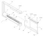
도 11은 본 발명에 따른 모니터 장치에서 LCD 모니터를 분리하여 도시한 사시도,11 is a perspective view showing the LCD monitor separated from the monitor device according to the present invention;
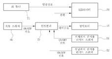
도 12는 본 발명에 따른 LCD 모니터 장치의 구성요소 간 신호 입출력 관계를 도시한 블럭도,12 is a block diagram showing signal input / output relationships between components of an LCD monitor device according to the present invention;
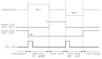
도 13은 본 발명에 따른 LCD 모니터 장치의 작동 타이밍 차트를 나타낸 도면.13 is a view showing an operation timing chart of an LCD monitor device according to the present invention;
<도면의 주요 부분에 대한 부호의 설명><Explanation of symbols for the main parts of the drawings>
1 : 루프4 : 선반1: loop 4: shelf
4a : 리드5 : 모니터 장치4a: lead 5: monitor unit
10 : 케이스11 : 상측 스토퍼10
12 : 하측 스토퍼13 : 고무패드12: lower stopper 13: rubber pad
20 : LCD 모니터21, 22 : 돌출단20:
30 : 결합/안내수단31 : 암 레일30: coupling / guide means 31: arm rail
32 : 수 레일40 : 이송수단32: male rail 40: transfer means
41 : 정역모터42 : 스크류 축41: forward and reverse motor 42: screw shaft
42a : 나사산43 : LCD 베이스42a: thread 43: LCD base
43a : 스토퍼단44 : 곡면 홈43a: stopper end 44: curved groove
44a : 나선형 홈45 : 질량블록44a: spiral groove 45: mass block
50 : 위치감지수단51, 52 : 리미트 스위치50: position sensing means 51, 52: limit switch
60 : 작동 스위치70 : 컨트롤 박스60: operation switch 70: control box
71 : 튜너72 : 컨트롤러71: tuner 72: controller
본 발명은 차량용 모니터 장치에 관한 것으로서, 더욱 상세하게는 다수의 승객이 탑승하는 버스나 기차 등의 차량 내부에 설치되는 중간 승객용 모니터 장치에 관한 것이다.The present invention relates to a vehicular monitor device, and more particularly, to an intermediate passenger monitor device installed in a vehicle such as a bus or a train on which a large number of passengers board.
일반적으로, 다수의 승객이 탑승하는 버스나 기차 등의 차량 내부에는 여행 중에 승객에게 더욱 고급화된 서비스를 제공하기 위하여 내부 또는 외부의 영상신호(TV, 비디오, 광고, 영화, 기타 각종 위성신호 등)를 전달받아 디스플레이하는 모니터가 설치된다.In general, in a vehicle such as a bus or a train in which a large number of passengers board, internal or external video signals (TV, video, advertisements, movies, various satellite signals, etc.) to provide more advanced services to passengers during a trip. The monitor is installed to receive and display.
특히, 버스에 설치되는 모니터는 종래의 경우에 주로 일반 가정용과 동일한 크기 및 종류의 CRT(Cathode Ray Tube) 모니터를 운전석 상측에 설치하여 승객들이 시청할 수 있도록 한 모니터가 주종을 이루었고, 이는 상당히 무거운 자체 중량을 가지므로 보통 별도 프레임 상에 얹혀져 설치되게 된다.In particular, the monitors installed on the bus are mainly made up of the same size and type of CRT (Cathode Ray Tube) monitors installed in the upper part of the driver's seat so that passengers can watch them. Since it has a weight, it is usually mounted on a separate frame.
최근에는 LCD(Liquid Crystal Display) 모니터가 널리 보급되면서 다수의 승객이 이용하는 버스나 기차 등의 모니터 역시 LCD 모니터로 대체되고 있으며, 이러 한 차량용 LCD 모니터는 통로 중간의 루프에 설치되는 것이 일반적이다.Recently, as liquid crystal display (LCD) monitors have become widespread, monitors such as buses and trains used by a large number of passengers have also been replaced by LCD monitors, and such vehicle LCD monitors are generally installed in a loop in the middle of an aisle.
첨부한 도 1과 도 2는 종래기술에 따른 차량용 LCD 모니터 장치의 예를 도시한 도면으로서, 특히 차량 실내의 중간 승객을 위한 종래의 LCD 모니터 장치를 도시한 것이며, 도 1은 LCD 모니터의 열린(open) 상태를, 도 2는 LCD 모니터의 닫힌(close) 상태를 도시한 것이다.1 and 2 are views illustrating an exemplary LCD monitor device for a vehicle according to the prior art, in particular, a conventional LCD monitor device for an intermediate passenger in a vehicle interior, and FIG. In the open state, Fig. 2 shows the closed state of the LCD monitor.
도시한 바와 같이, 대형버스나 기차에 장착되는 중간 승객용 LCD 모니터 장치는 차량 실내 통로 중간의 루프(1)에 장착되고 있으며, LCD 모니터(3)가 루프(1)에 결합된 상단의 회전축을 중심으로 상하 회전하여 개폐되는 접이식 형태로 부착된다.As shown, an intermediate passenger LCD monitor device mounted on a large bus or train is mounted in a
즉, 상기 LCD 모니터(3)의 상단부에 설치된 회전축이 루프에 고정 설치된 지지대(2)에 회전 가능하도록 결합되어 있는 바, LCD 모니터(3)가 회전축을 중심으로 하방으로 회전하여 세워짐으로써 작동상태, 즉 열린 상태가 되며(도 1 참조), 반대로 LCD 모니터(3)가 회전축을 중심으로 상방으로 회전하여 루프(1)에 근접되도록 접혀짐으로써 비작동상태, 즉 닫힌 상태가 된다(도 2 참조).That is, the rotary shaft installed in the upper end of the
그러나, 상기와 같은 종래의 버스용 LCD 모니터 장치에서는 다음과 같은 문제점이 있었다.However, the conventional LCD monitor for buses has the following problems.
우선, LCD 모니터 장치가 버스 통로 중간의 루프에 장착되므로, 도 1에 나타낸 바와 같이 LCD 모니터(3)의 열린 상태, 즉 LCD 모니터(3)가 하방으로 내려와 세워진 상태에서는 승, 하차하는 승객의 머리가 닿게 된다.First, since the LCD monitor device is mounted in the loop in the middle of the bus passage, as shown in FIG. 1, the head of the passenger who gets on or off the passenger in the open state of the
즉, 승객이 승, 하차할 때 머리가 LCD 모니터(3)의 하단부에 부딪히는 일이 자주 발생하고 있으며, 이와 같이 LCD 모니터(3)가 통로 중간에 설치됨으로 해서 승객의 출입성이 나빠지게 된다.That is, when the passengers get on and off, the head often hits the lower end of the
또한 기존의 접이식 LCD 모니터는 무게중심이 하단부에 있음에도 불구하고 도시한 바와 같이 회전축이 LCD 모니터(3)의 상단에 위치하고 있어, 상단의 회전축을 중심으로 회전운동을 할 때 LCD 모니터(3)의 회전을 위한 모터(미도시됨)에 많은 부하(torque)가 걸리게 되며, 이로 인해 모터의 내구성에 나쁜 영향을 주게 된다.In addition, although the existing folding LCD monitor has a center of gravity at the lower end, as shown in the figure, the rotating shaft is positioned at the top of the LCD monitor (3), so that the rotation of the LCD monitor (3) is rotated about the upper rotating shaft. A large load (torque) is applied to the motor (not shown) for the motor, which adversely affects the durability of the motor.
그리고, LCD 모니터(3)의 비작동상태, 즉 닫힌 상태에서는 도 2에 나타낸 바와 같이 LCD 모니터(3)가 회전축을 중심으로 상방으로 접혀져 루프(1)에 근접되게 위치하게 되는데, 이 상태에서 LCD 모니터(3)가 중력 및 차량의 상하 진동(도 2의 화살표 방향임)에 의하여 고정상태를 유지하기가 어렵다.In the non-operational state of the
이로 인해 LCD 모니터(3)를 닫힌 상태로 고정하기 위한 고정 메커니즘에 고장이 자주 발생하고 있으며, 또한 나중에는 회전 메커니즘에도 문제가 발생하게 된다.This often causes a failure in the fixing mechanism for fixing the
따라서, 본 발명은 상기와 같은 문제점을 해결하기 위하여 발명한 것으로서, 차량 실내 루프 측면부에 설치된 선반 내부의 케이스에서 이송수단에 의해 측방으로 슬라이드 이동하여 통로 측으로 돌출 전개되거나 선반 내측으로 완전히 매립되어 수납될 수 있게 구성됨으로써, 사용하지 않을 경우에 LCD 모니터가 선반 내측으 로 완전히 매립된 상태로 수납되어 외부 돌출되지 않는 바, 통로를 통해 승, 하차하는 승객의 출입성이 좋아지는 차량용 모니터 장치를 제공하는데 그 목적이 있다.Therefore, the present invention is invented to solve the above problems, in the case inside the shelf installed in the vehicle interior roof side portion is moved to the side by the slide means by the conveying means to be deployed to protrude toward the passage or completely embedded inside the shelf to be stored When not in use, the LCD monitor is completely stored inside the shelf is stored in the state that does not protrude outside the bar, provides a vehicle monitor device for the passengers to get in and out through the passage better. There is a purpose.
또한 본 발명은 LCD 모니터가 케이스 내부에 레일 결합구조로 결합된 상태에서 측방으로 밀어주거나 당겨주도록 된 이송수단에 의해 측방 슬라이드 이동하여 전개 또는 수납되는 바, 회전축을 중심으로 중량을 가지는 LCD 모니터가 공중에서 상하 회전하는 종래의 모니터에 비해 안정적이고 신뢰적으로 작동이 가능한 차량용 모니터 장치를 제공하는데 그 목적이 있다.In another aspect, the present invention is the LCD monitor has a slide around the side by the slide means to be pushed or pulled to the side in the state coupled to the rail coupling structure inside the case is deployed or received, the LCD monitor having a weight around the axis of rotation is air It is an object of the present invention to provide a vehicle monitor device that can operate stably and reliably compared to a conventional monitor that rotates up and down.
또한 본 발명은 구동부에 무리가 가는 회전운동을 하는 종래의 모니터 장치에 비해 구동부가 밀고 당겨주어 LCD 모니터가 레일을 따라 슬라이드 이동하는 방식이므로 구동부의 내구성에 아무런 문제가 없으며, 긴 사용수명을 가지는 차량용 모니터 장치를 제공하는데 그 목적이 있다.In addition, the present invention has no problem in the durability of the drive unit because the LCD monitor slides along the rails by pushing and pulling the drive unit compared to the conventional monitor device that makes a rotational movement to the drive unit, there is no problem in the durability of the vehicle for a long service life The purpose is to provide a monitor device.
또한 본 발명은 차량의 상하 진동상태에서도 안정적으로 수납될 수 있고, 종래와 같이 고정상태를 유지하기가 위한 고정 메커니즘의 고장, 회전 메커니즘의 고장 등이 발생하지 않는 차량용 모니터 장치를 제공하는데 그 목적이 있다.In addition, the present invention can be stably accommodated even in the up and down vibration state of the vehicle, the object of the present invention to provide a vehicle monitor device that does not occur the failure of the fixing mechanism, the rotation mechanism for maintaining the fixed state as in the prior art have.
이하, 첨부한 도면을 참조하여 본 발명을 상세히 설명하면 다음과 같다.Hereinafter, the present invention will be described in detail with reference to the accompanying drawings.
상기한 목적을 달성하기 위해, 본 발명은, 차량용 모니터 장치에 있어서,In order to achieve the above object, the present invention provides a vehicle monitor device,
차량 실내 루프 측면부에 장착된 선반 내부에 설치되는 케이스와; 상기 케이스 내부에 결합/안내수단을 매개로 측방 슬라이드 이동이 가능하도록 조립되고, 측 방 슬라이드 이동함에 따라 케이스 내부를 출입하면서 상기 케이스 내부에 수납 및 외부로 돌출 전개되는 LCD 모니터와; 상기 케이스에 설치되어 LCD 모니터의 위치를 감지하기 위한 위치감지수단과; 사용자의 작동 스위치 조작에 따른 신호와 상기 위치감지수단의 신호를 토대로 LCD 모니터를 완전 수납위치와 완전 전개위치가 되도록 이송하기 위한 제어신호를 출력하는 컨트롤러와; 상기 컨트톨러가 출력하는 제어신호에 따라 상기 LCD 모니터를 완전 수납위치와 완전 전개위치 사이에서 측방 슬라이드 이동시키는 이송수단;을 포함하여 구성되는 것을 특징으로 하는 차량용 모니터 장치를 제공한다.A case installed inside a shelf mounted on a vehicle interior roof side portion; An LCD monitor which is assembled to allow the side slide movement through the coupling / guiding means in the case, and moves in and out of the case as the side slide moves, and protrudes and expands into the case; Position sensing means installed on the case to sense a position of the LCD monitor; A controller for outputting a control signal for transferring the LCD monitor to a fully received position and a fully deployed position based on a signal according to a user's operation switch operation and a signal of the position detecting means; And a transfer means for laterally sliding the LCD monitor between the fully received position and the fully deployed position according to the control signal output from the controller.
바람직하게는, 상기 완전 수납위치에서 상기 LCD 모니터가 선반 내부공간에 완전 매립된 상태가 되는 한편 측방 슬라이드 이동 후 상기 완전 전개위치에서는 상기 LCD 모니터가 선반에서 통로 측 방향으로 전개된 상태가 될 수 있도록, 상기 케이스를 포함한 상기 구성요소들이 선반 리드와 리드 사이 위치의 선반 내부공간에 내장되는 것을 특징으로 한다.Preferably, the LCD monitor is completely embedded in the interior space of the shelf at the fully retracted position, while the LCD monitor is unfolded from the shelf to the passage in the fully deployed position after the side slide movement. The components including the case are embedded in a shelf interior space at a position between the shelf lead and the lead.
그리고, 상기 결합/안내수단은 상기 케이스의 상부 내측면과 상기 LCD 모니터의 상단에 그 측방의 길이방향을 따라 설치되어 상호 간 슬라이드 가능하도록 결합되는 암 레일과 수 레일로 구성되는 것을 특징으로 한다.And, the coupling / guide means is characterized in that the upper inner surface of the case and the upper end of the LCD monitor is installed in the longitudinal direction of the side of the female rail and male rail coupled to be slidably mutually.
또한 상기 위치감지수단은, 각각 상기 LCD 모니터의 상단 일측단 및 상단 타측단의 돌출단에 설치되는 수납위치 감지용 리미트 스위치 및 전개위치 감지용 리미트 스위치와; 상기 LCD 모니터의 완전 수납위치에서 상기 수납위치 감지용 리미트 스위치를 눌러주는 한편 상기 LCD 모니터의 완전 전개위치에서 상기 전개위치 감지용 리미트 스위치를 눌러주도록 상기 케이스 입구부 내측면에 하방으로 돌출 설치된 상측 스토퍼;를 포함하여 구성되는 것을 특징으로 한다.In addition, the position detecting means, the storage position detection limit switch and the deployment position detection limit switch is installed on the protruding end of the upper end and the other end of the LCD monitor, respectively; An upper stopper protruding downwardly on the inner side of the case inlet part to press the limit position for detecting the storage position at the fully retracted position of the LCD monitor and press the limit switch for detecting the deployed position at the fully deployed position of the LCD monitor; It characterized by comprising;
또한 상기 이송수단은, 상기 케이스 내부공간의 하단부 일측단에 설치되어, 상기 컨트롤러가 출력하는 제어신호에 따라 정역회전이 제어되는 정역모터와; 일단이 상기 정역모터의 회전축과 일체로 연결되고, 타단이 상기 케이스 내부공간의 하단부 타측단에 설치된 하측 스토퍼에 회전 가능하도록 결합되며, 그 축상에는 상기 LCD 모니터의 하단부에 일체로 설치된 LCD 베이스가 결합되어, 상기 정역모터의 회전구동시에 회전하면서 그 회전방향에 따라 상기 LCD 베이스를 매개로 LCD 모니터를 측방으로 밀고 당겨주는 스크류 축;을 포함하여 구성되는 것을 특징으로 한다.In addition, the transfer means, a forward and reverse motor is installed at one end of the lower end of the inner space of the case, the forward and reverse rotation is controlled according to the control signal output from the controller; One end is integrally connected with the rotating shaft of the stationary motor, the other end is rotatably coupled to the lower stopper installed at the other end of the lower end of the inner space of the case, and the LCD base is integrally installed on the lower end of the LCD monitor on the shaft. It is characterized in that it comprises a; screw shaft for pushing and pulling the LCD monitor to the side via the LCD base according to the rotation direction while rotating at the time of rotation of the stationary motor.
그리고, 상기 LCD 베이스는 상기 스크류 축상에 안착된 상태로 결합될 수 있도록 그 하면에 반원형 곡면 홈이 형성되고 상기 반원형 곡면 홈의 내주면에 상기 스크류 축의 나사산이 맞물려 결합될 수 있는 나선형 홈이 형성된 구조인 것을 특징으로 한다.In addition, the LCD base has a structure in which a semicircular curved groove is formed at a lower surface thereof so as to be coupled on the screw shaft, and a spiral groove is formed in which a screw thread of the screw shaft is engaged with an inner circumferential surface of the semicircular curved groove. It is characterized by.
또한 상기 LCD 베이스에서 바깥쪽의 일측 끝단부에는 하방으로 돌출 연장된 스토퍼 단이 형성되어 있고, LCD 모니터가 케이스 내부에 완전히 수납될 때 상기 스토퍼 단은 상기 하부 스토퍼에 접촉하여 걸리도록 된 것을 특징으로 한다.In addition, a stopper end protruding downwardly is formed at one end of the outer side of the LCD base, and the stopper end is caught by contacting the lower stopper when the LCD monitor is completely stored in the case. do.
또한 상기 하부 스토퍼에서 상기 스토퍼 단과 접촉하는 면에는 충격 흡수용 고무패드가 부착되는 것을 특징으로 한다.In addition, the surface of the lower stopper in contact with the stopper end is characterized in that the shock-absorbing rubber pad is attached.
또한 상기 LCD 베이스에서 안쪽의 타측 끝단부에는 케이스 외부로 전개된 LCD 모니터와의 무게 균형을 맞춰줄 수 있는 질량블록이 일체로 부착 설치되는 것 을 특징으로 한다.In addition, the other end of the inner side of the LCD base is characterized in that the mass block that can be installed integrally attached to balance the weight with the LCD monitor deployed to the outside of the case.
이하, 첨부한 도면을 참조하여 본 발명의 바람직한 실시예에 대해 더욱 상세히 설명하면 다음과 같다.Hereinafter, preferred embodiments of the present invention will be described in detail with reference to the accompanying drawings.
본 발명은 차량용 모니터 장치에 관한 것으로서, 다수의 승객이 탑승하는 버스나 기차 등의 차량 내부에 설치되는 중간 승객용 모니터 장치에 관한 것이다.BACKGROUND OF THE
특히, 본 발명은 버스나 기차 등의 차량 실내에서 루프 좌, 우측에 설치된 선반의 내부공간을 이용하여 선반의 리드(lid)와 리드 사이에 LCD 모니터가 매립형으로 수납될 수 있도록 구성된 모니터 장치이며, 상기 LCD 모니터, 좌, 우측 선반 내에 설치되어 LCD 모니터가 수납될 수 있게 된 케이스, 사용을 위하여 상기 케이스 내부에서 LCD 모니터를 통로 측으로 이동시키고 반대로 사용하지 않을 경우에는 상기 케이스 내부로 수납시키는 기계적/전기적 기구를 포함하여 구성되는 것이다.In particular, the present invention is a monitor device configured to be accommodated in a buried type LCD monitor between the lid (lid) and the lid of the shelf using the inner space of the shelf installed on the left and right of the roof in a vehicle such as a bus or train, The case is installed in the LCD monitor, left and right shelves to accommodate the LCD monitor, the mechanical / electrical to move the LCD monitor to the passage side in the case for use, and to accommodate the inside of the case when not in use It is configured to include a mechanism.
이와 같이 본 발명의 모니터 장치는 LCD 모니터가 사용하지 않을 경우에 선반 내 케이스에 수납되어 선반 내부공간에 매립되고, 사용 중에는 선반 내부공간의 케이스에서 측방 슬라이드 이동하여 실내 통로 측에 위치하도록 구성된다.As described above, the monitor device of the present invention is stored in the case inside the shelf when the LCD monitor is not in use, and is embedded in the shelf internal space.
물론, 사용 후에는 실내 통로 측에 위치한 LCD 모니터가 반대로 측방 슬라이드 이동하여 선반의 내부공간에 매립되어진다.Of course, after use, the LCD monitor located on the indoor passage side is lateral slided to the contrary and embedded in the interior space of the shelf.
첨부한 도 3은 본 발명에 따른 차량용 모니터 장치의 설치위치를 보여주기 위한 설치상태도로서, 특히 LCD 모니터(20)가 루프(1) 좌, 우 측면부에 설치된 선반(4) 내부의 케이스에 완전히 수납된 상태를 보여주고 있다.FIG. 3 is an installation state diagram for showing an installation position of a vehicle monitor apparatus according to the present invention. In particular, the
도 3에 도시한 바와 같이 좌, 우측의 모니터 장치(5)가 각각 좌, 우측의 선 반(4)에 설치되는데, 특히 케이스를 포함한 모든 구성요소가 선반(4)의 리드(4a)와 리드 사이 위치에서 선반(4)의 내부공간에 내장되고, LCD 모니터(20)가 케이스 내부로 완전히 수납된 상태에서는 선반(4) 외부로는 어떠한 구성요소도 돌출되지 않으므로, 승객이 승, 하차하는데 모니터 장치(5)에 의해 지장을 받는 일은 없게 된다.As shown in Fig. 3, the left and
첨부한 도 4와 도 5는 본 발명에 따른 모니터 장치(5)의 구성요소를 도시한 도면으로서, 케이스(10) 등을 포함하여 선반(4) 내부에 설치되는 부속된 각 구성요소들을 보여주고 있다.4 and 5 are diagrams illustrating the components of the
도 4는 루프(1) 측면부의 선반(4) 내부공간에 설치된 케이스(10)에 LCD 모니터(20)가 완전히 수납된 상태를, 도 5는 LCD 모니터(20)가 사용을 위하여 케이스(10)로부터 통로 측으로 완전히 전개된 상태를 보여주고 있다.4 illustrates a state in which the
본 발명의 모니터 장치(5)에서 LCD 모니터(20)는 도 4와 도 5에 나타낸 바와 같이 수납(LCD 모니터의 미사용) 및 전개(LCD 모니터의 사용)를 위하여 도면상의 좌우 측방으로 왕복이동이 가능하도록 되어 있으며, 이러한 LCD 모니터(20)의 좌우 왕복이동을 위하여 선반(4) 내부공간의 케이스(10)에는 그 내부에서 LCD 모니터(20)를 좌우로 왕복 슬라이드 이동시키기 위한 이송수단(40)이 설치된다.In the
도 4의 상태에서 사용을 위해서는 LCD 모니터(20)가 선반(4) 내부공간의 케이스(10)로부터 측방 슬라이드 이동하여 도 5에 나타낸 바와 같이 선반(4)에서 통로 측으로 완전 돌출 전개된 상태가 되며, 사용하지 않을 경우에는 도 5의 상태에서 다시 반대로 케이스(10) 내측으로 측방 슬라이드 이동하여 도 4에 나타낸 바와 같이 선반(4) 내부공간에 완전히 매립되어진다.For use in the state of FIG. 4, the
도시한 예에서는 좌, 우측 선반(4)에 각각 하나씩의 모니터 장치(5)가 설치됨을 보여주고 있는 바, 이와 같이 본 발명의 모니터 장치(5)는 좌, 우측 선반(4)에 각각 설치될 수 있고, 또는 좌, 우측 선반(4) 중에 어느 한쪽에만 설치될 수도 있으며, 도면으로 나타내지는 않았지만 차량 전후방향을 따라 복수개의 모니터 장치가 선반 쪽에 설치될 수도 있다.In the illustrated example, one
종래의 실내 루프에 장착된 접이식 모니터는 열린 상태로 작동 중에 승객이 통로를 지날 때 머리를 부딪히는 문제가 있어 매우 불편하나, 본 발명에 따르면 버스 실내 양측 선반(4)에 매립되어 있는 LCD 모니터(20)가 좌우 왕복운동을 통하여 작동되므로 승객 출입성을 개선할 수 있으며, 작동 중(통로 측으로 전개된 상태)에 LCD 모니터(20)가 승객 통로 바로 위가 아니라 선반(4) 쪽에 근접하여 측방에 위치하므로 승객의 출입성에 문제가 없게 된다.The folding monitor mounted in the conventional indoor roof is very inconvenient because of the problem of hitting the head when the passenger passes the aisle while operating in the open state, but according to the present invention, the
또한 종래의 LCD 모니터는 상단 회전축을 중심으로 상하 회전하는 구조이므로 개폐 동작시 내구/신뢰성에 문제가 많이 발생하는 구조이나, 본 발명에 따른 모니터 장치(5)에서는 LCD 모니터(20)가 정역회전이 가능한 모터와 연결된 스크류 축(42)의 회전운동에 의해 측방으로 슬라이드 이동하므로 안정적인 동작이 가능하도록 되어 있다.In addition, the conventional LCD monitor has a structure that rotates up and down about the upper axis of rotation, so that a lot of problems in durability / reliability during the opening and closing operation, but in the
이하, 본 발명에 따른 모니터 장치의 구성에 대해 첨부한 도면을 참조하여 좀더 상세히 설명하기로 한다.Hereinafter, a configuration of a monitor apparatus according to the present invention will be described in detail with reference to the accompanying drawings.
첨부한 도 6은 본 발명에 따른 모니터 장치의 구성도로서, LCD 모니터(20)가 전개된 상태의 정면도이다.6 is a front view of a state where the
또한 첨부한 도 7은 본 발명에 따른 모니터 장치에서 LCD 모니터가 수납된 상태의 정면도이고, 도 8은 도 7의 선 'A-A'를 따라 취한 단면도이다.7 is a front view of the LCD monitor accommodated in the monitor device according to the present invention, and FIG. 8 is a cross-sectional view taken along the line 'A-A' of FIG. 7.
또한 첨부한 도 9는 본 발명에 따른 모니터 장치에서 LCD 모니터가 수납된 상태의 사시도이고, 도 10은 LCD 모니터가 전개된 상태의 사시도이며, 도 11은 LCD 모니터를 분리하여 도시한 사시도이다.9 is a perspective view of the LCD monitor is accommodated in the monitor device according to the present invention, Figure 10 is a perspective view of the LCD monitor is deployed, Figure 11 is a perspective view showing the LCD monitor separated.
도시한 바와 같이, 본 발명의 모니터 장치(5)는, LCD 모니터(20)와, 상기 LCD 모니터(20)가 수납되는 케이스(10)와, 상기 케이스(10) 내부에 설치되어 LCD 모니터(20)를 케이스(10)에 수납시키거나 케이스(10)로부터 측방 전개시키기 위해 이동시키는 이송수단(40)을 포함하여 구성된다.As illustrated, the
본 발명에서의 LCD 모니터(20)는 구동시에 외부의 신호를 전달받아 영상출력 및 음성출력 등을 수행하는 바, 통상적인 LCD 모니터(20)와 비교할 때 그 구성면에서 큰 차이가 없으며, 기존 LCD 모니터와 마찬가지로 튜너(71) 등 각종 구동부 및 컨트롤러(72)가 내장된 컨트롤 박스(70)를 구비하고, 또한 외부에서 운전자나 승객이 조작할 수 있는 작동 스위치(60)를 구비한다.In the present invention, the
상기 컨트롤 박스(70)에는 LCD 모니터(20)의 구동을 위한 구성요소 외에 후술하는 바와 같이 LCD 모니터(20)의 측방 이동을 위한 이송수단(40)의 작동을 제어하기 위한 구성요소가 내장된다.In addition to the components for driving the
그리고, 상기 케이스(10)는 선반(4) 내부공간에 설치되는데, 이는 본 발명에 따른 모니터 장치(5)의 외곽을 형성하는 것으로서, 선반(4)의 리드(4a)와 리드 사 이의 공간에 위치되어 내장되며, 내부에 결합된 LCD 모니터(20)가 측방으로 왕복이동할 수 있는 구조로 되어 있다.In addition, the
그리고, 상기 케이스(10)와 LCD 모니터(20)의 사이에는 케이스(10)와 LCD 모니터(20)를 상호 결합하고 동시에 케이스(10)에서 LCD 모니터(20)의 측방 이동을 안내하기 위한 결합/안내수단(30)이 구비되는 바, 이 결합/안내수단(30)은 케이스(10)와 LCD 모니터(20)에 각각 설치된 레일로 구성된다.In addition, between the
즉, 상기 케이스(10)의 상부 내측면에는 LCD 모니터(20)의 좌우 이동시 경로를 안내하기 위한 암 레일(31)이 측방의 케이스(10) 길이방향을 따라 길게 설치되고, 상기 LCD 모니터(20)의 상단에는 상기 케이스(10)의 암 레일(31)에 삽입 결합된 상태에서 케이스(10)의 암 레일(31)을 따라 안내되도록 된 수 레일(32)이 돌출 형성된다.That is, an
상기 케이스(10)의 암 레일(31)과 상기 LCD 모니터(20)의 수 레일(32)은 상호 간에 결합된 상태에서 좌우 측방 이동하는 LCD 모니터(20)가 케이스(10)의 정해진 경로를 따라 이동할 수 있도록 안내하는 역할을 하게 된다.The
상기 케이스(10)와 LCD 모니터(20)에는 상기한 바와 같이 각각 암 레일(31)과 수 레일(32)이 설치되어 수 레일(32)이 암 레일(31)에 삽입 결합된 상태로 조립되고, 이와 같이 두 레일이 조립된 상태에서 수 레일(32)이 암 레일(31)을 따라 이동할 수 있게 되어 있으므로, LCD 모니터(20)는 케이스(10)와의 레일 결합구조에 의해 케이스(10)의 내부와 외부 사이를 보다 안정적으로 이동할 수 있게 된다.The
이와 같은 레일 결합구조에 의해 본 발명에서 LCD 모니터(20)는 케이스(10) 내부에서 외부로, 케이스(10) 외부에서 내부로 슬라이드 이동할 수 있으며, 특히 LCD 모니터(20)가 슬라이드 이동시에 좌우 측방으로 이동하도록 되어 있다.By the rail coupling structure as described above, the
이때, LCD 모니터(20)의 수 레일(32)이 케이스(10)의 암 레일(31)을 따라 이동하면서 선반(4) 내부공간에 설치된 케이스(10)의 외부로 LCD 모니터(20)가 전개 작동하게 되면 LCD 모니터(20)는 도 3에 나타낸 바와 같이 통로 측으로 돌출되고, 반대로 통로 측에서 케이스(10)의 내부로 LCD 모니터(20)가 삽입 이동하게 되면 LCD 모니터(20)는 도 4에 나타낸 바와 같이 선반(4)에서 그 내부공간으로 완전 매립되게 된다.At this time, while the
도시한 실시예에서, 암 레일(31)이 케이스(10)에, 수 레일(32)이 LCD 모니터(20)에 각각 설치되고 있으나, 반대로 암 레일(31)이 LCD 모니터(20)에, 수 레일(32)이 케이스(10)에 설치될 수도 있다.In the illustrated embodiment, the
그리고, 상기 케이스(10)와 LCD 모니터(20) 사이에는 LCD 모니터(20)의 수납위치와 전개위치를 감지하기 위한 위치감지수단(50)이 설치되는 바, 상기 위치감지수단(50)은 두 개의 리미트 스위치(51,52)를 포함하여 구성될 수 있다.In addition, between the
바람직한 실시예에서, 상기 리미트 스위치(51,52)는 LCD 모니터(20)에 설치될 수 있으며, 이때 두 개의 리미트 스위치(51,52)가 LCD 모니터(20)의 상단 일측단과 상단 타측단에 각각 형성된 돌출단(21,22)에 설치된다.In a preferred embodiment, the limit switches 51 and 52 may be installed in the
상기 리미트 스위치 중 하나는 LCD 모니터(20)의 완전 전개된 위치를 감지하기 위한 것이고, 나머지 다른 하나는 LCD 모니터(20)의 완전 수납된 위치를 감지하기 위한 것으로, 두 리미트 스위치(51,52) 모두 상기 케이스(10) 입구부 내측면에 하방으로 돌출 설치된 상측 스토퍼(11)에 의해 누름조작될 수 있도록 되어 있으며, 상측 스토퍼(11)가 접촉하여 누름조작하는 경우에 온(on)되도록 구비된다.One of the limit switches is for detecting the fully deployed position of the
즉, LCD 모니터(20)가 케이스(10)로부터 완전히 전개된 위치로 이동하게 되면 상기 케이스(10)의 상측 스토퍼(11)가 LCD 모니터(20)의 일측단에 설치된 리미트 스위치(51)를 눌러주어 온 시키고, 반대로 LCD 모니터(20)가 케이스(10) 내부에 완전히 수납된 위치로 이동하게 되면 상기 케이스(10)의 상측 스토퍼(11)가 LCD 모니터(20)의 타측단에 설치된 리미트 스위치(52)를 눌러주어 온 시키도록 되어 있는 것이다.That is, when the
또한 이와 같이 LCD 모니터(20)가 정해진 위치로 완전히 수납되거나 반대로 정해진 위치로 완전히 전개되었을 때 케이스(10)의 상측 스토퍼(11)에 의해 누름조작되어 온 되는 각 리미트 스위치(51,52)는 컨트롤러(72)와 연결되어 있는 바, 상측 스토퍼(11)가 눌러주어 각 리미트 스위치(51,52)가 온 되었을 때 리미트 스위치의 온 조작에 따른 통전상태, 즉 리미트 스위치의 온 신호를 상기 컨트롤러(72)가 입력받게 되어 있으며, 이를 통해 컨트롤러(72)는 LCD 모니터(20)의 수납위치 도달과 전개위치 도달을 인지할 수 있게 된다.In addition, when the
한편, 컨트롤러(72)의 제어신호에 따라 LCD 모니터(20)를 측방 왕복이동시켜 주는 이송수단(40)에 대해 설명하면 다음과 같다.On the other hand, the transfer means 40 for reciprocating the
우선, 케이스(10) 내부공간의 하단부 일측단에는 컨트롤러(72)의 제어신호에 의해 구동이 제어되는 정역모터(41)가 설치되고, 상기 정역모터(41)의 회전축에는 스크류 축(42)이 일체로 연결 설치된다.First, a forward and reverse
여기서, 상기 스크류 축(42)의 일단은 정역모터(41)의 회전축과 일체로 되어 있으며, 상기 스크류 축(42)의 타단은 케이스(10) 내부공간의 하단부 타측단, 즉 정역모터(41) 반대쪽에 설치된 하측 스토퍼(12)에 결합된다.Here, one end of the
상기 스크류 축(42)은 그 길이방향을 따라 나사산(42a)이 돌출 형성된 구조로 되어 있다.The
그리고, 상기 LCD 모니터(20)의 하단부에는 스크류 축(42)에 맞물려 결합되는 것으로서 LCD 베이스(43)가 설치되는 바, 이 LCD 베이스(43)의 하면은 스크류 축(42)상에 안착된 상태로 결합될 수 있도록 반원형 곡면 홈(44)으로 되어 있고, 특히 반원형 곡면 홈(44) 내면에는 스크류 축(42)의 나사산(42a)이 결합될 수 있도록 나선형 홈(44a)이 일정 간격으로 형성된다.In addition, the
결국, LCD 모니터(20)는 스크류 축(42)상에 LCD 베이스(43)를 매개로 안착되어 조립되는 것이며, 스크류 축(42)의 회전에 의해 스크류 축(42)의 길이방향을 따라 LCD 모니터(20)가 이동하게 되는 것이다.As a result, the
상기 스크류 축(42)이 회전할 때 스크류 축(42)의 나사산(42a)이 LCD 베이스(43)의 나선형 홈(44a)을 따라 밀어주고 당겨줌으로써 LCD 베이스(43)가 스크류 축(42)의 길이방향을 따라 이동하게 된다.When the
이와 같이 정역모터(41)가 회전구동하고 이에 의해 구동축인 스크류 축(42)이 회전함에 따라 스크류 결합된 LCD 베이스(43)가 축 길이방향을 따라 이동함으로써 LCD 모니터(20)가 좌우 측방 이동하게 되는 것이며, 이때 정역모터(41) 및 스크류 축(42)의 회전방향에 따라 LCD 모니터(20)의 진행방향이 결정되고 변경된다.As the forward /
그리고, 상기 LCD 베이스(43)에서 바깥쪽의 일측 끝단부에는 하방으로 돌출 연장된 스토퍼 단(43a)이 형성되어 있고, 이 스토퍼 단(43a)에는 LCD 모니터(20)가 케이스(10) 내부에 완전히 수납될 때 케이스(10)의 하부 스토퍼가 접촉하여 걸리도록 되어 있으며, 바람직하게는 상기 하부 스토퍼의 접촉면에 고무패드(13)를 부착한다.In addition, a
상기 고무패드(13)는 LCD 모니터(20)가 수납되면서 LCD 베이스(43)의 스토퍼 단(43a)이 케이스(10)의 하측 스토퍼(12)에 접촉하게 될 때 충격을 흡수하게 된다.The
그리고, 상기 LCD 모니터(20)의 내측 측단에는 컨트롤 박스(70)가 설치되고, 이 컨트롤 박스(70) 하측으로 LCD 베이스(43) 안쪽의 타측 끝단부에는 질량블록(45)이 설치되는 바, 이 질량블록(45)은 스틸을 재질로 하여 제작되어 케이스(10) 외부로 전개된 LCD 모니터(20)의 무게중심을 잡아주는 역할을 하게 된다.In addition, a
상기 질량블록(45)은 케이스(10) 외부로 전개될 때 공중에 떠있는 상태가 되는 LCD 모니터(20)가 그 자중에 의해 기울거나 상측의 레일 간에 과도한 힘이 가해지는 것을 방지하고 LCD 베이스(43)가 스크류 축(42)상에 최적 상태로 결합되어 이동될 수 있도록 LCD 모니터(20)의 무게중심을 잡아주도록 설치되는 것으로, 상기와 같이 질량블록(45)이 설치됨으로써 질량블록(45)의 자중이 케이스(10) 외부로 전개되어 공중에 떠있게 되는 LCD 모니터(20)의 자중과 어느 정도 균형을 맞추도록 되어 있으며, 이를 통해 질량블록(45)은 LCD 모니터(20)의 안정적인 이동이 가능하도록 보조하게 된다.The
한편, 첨부한 도 12는 본 발명에 따른 차량용 모니터 장치의 구성요소 간 신 호 입출력 관계를 도시한 블럭도이고, 도 13은 작동 타이밍 차트를 나타낸 도면으로서, 이를 설명하면 다음과 같다.Meanwhile, FIG. 12 is a block diagram illustrating signal input / output relationships between components of the vehicle monitor apparatus according to the present invention, and FIG. 13 is a view illustrating an operation timing chart.
도 12에는 컨트롤 박스(70)에 내장된 AV 튜너(71)와 컨트롤러(72), 외부의 작동 스위치(60), 위치감지수단의 두 리미트 스위치(51,52), LCD 모니터(20), LCD 모니터(20)를 이동시키기 위한 이송수단의 정역모터(41)가 도시되어 있다.12 shows an
우선, 모니터 미사용시에는 전개위치 감지용 리미트 스위치(51)가 오프(off) 상태이고, 수납위치 감지용 리미트 스위치(52)는 온(on) 상태이며, 컨트롤러(72)를 통해 LCD 모니터(20)로 어떠한 신호도 입력되지 않는다.First, when the monitor is not in use, the deployment position detecting
물론, LCD 모니터(20)로의 전원 공급도 안되는 상태이다.Of course, power is not supplied to the
이후, 모니터 사용을 위해 사용자가 작동 스위치(60)를 온 조작하면, 작동 스위치(60)의 온 조작에 따른 신호가 컨트롤러(72)에 입력되고, 컨트롤러(72)가 LCD 모니터(20)에 전원을 공급하게 된다.Thereafter, when the user turns on the
또한 LCD 모니터(20)가 켜지면서 컨트롤러(72)로부터 전달되는 신호에 의해 AV 튜너(71)가 작동하여 LCD 모니터(20)에 영상신호를 출력하며, 이에 따라 LCD 모니터(20)에 영상이 출력되기 시작한다.In addition, when the
또한 컨트롤러(72)가 출력하는 제어신호에 의해 정역모터(41)가 정회전 구동되어 LCD 모니터(20)가 선반(4) 및 케이스(10)에서 나오기 시작하며, LCD 모니터(20)가 정해진 전개위치에 도달하게 되면 전개위치 감지용 리미트 스위치(51)가 케이스(10)의 상측 스토퍼(11)에 의해 누름조작되면서 온 상태가 된다.In addition, the normal and
이와 같이 전개위치 감지용 리미트 스위치(51)가 온 상태가 되면, 컨트롤 러(72)가 스위치 온 조작에 따른 신호를 입력받아 LCD 모니터(20)의 전개위치 도달을 감지하고, 이와 동시에 정역모터(41)의 구동을 중지하여 측방으로 전개되던 LCD 모니터(20)의 이동을 정지시키게 된다.When the deployment position detecting
이때, LCD 모니터(20)의 화면을 통해서는 AV 튜너(71)로부터 영상신호가 전송되면서 계속해서 영상이 출력되며, 승객들은 LCD 모니터(20)를 시청하게 된다.At this time, the image is continuously output while the image signal is transmitted from the
그리고, LCD 모니터(20)를 시청하는 동안 전개위치 감지용 리미트 스위치(51)는 온 상태를 유지하게 된다.Then, while the
한편, 모니터 사용을 중지하기 위해 사용자가 작동 스위치(60)를 오프 조작하면, 작동 스위치(60)의 오프 조작에 따른 신호가 컨트롤러(72)에 입력되고, 컨트롤러(72)가 LCD 모니터(20)에 전원을 차단하게 된다.On the other hand, when the user turns off the
또한 LCD 모니터(20)가 꺼지면서 컨트롤러(72)로부터 전달되는 신호에 의해 AV 튜너(71)의 작동도 중지되며, 동시에 컨트롤러(72)가 출력하는 제어신호에 의해 정역모터(41)가 역회전 구동되어 LCD 모니터(20)가 선반(4) 및 케이스(10) 내부로 들어가기 시작한다.In addition, as the
LCD 모니터(20)가 수납위치로 이동을 개시하는 순간 전개위치 감지용 리미트 스위치(51)는 케이스(10)의 상측 스토퍼(11)와의 접촉이 해제되면서 오프 상태가 되고, 이후 LCD 모니터(20)가 케이스(10) 내부로 완전히 수납되면 이번에는 수납위치 감지용 리미트 스위치(52)가 케이스(10)의 상측 스토퍼(11)에 의해 누름조작되면서 온 상태가 된다.As soon as the LCD monitor 20 starts to move to the storage position, the deployment position detecting
이와 같이 수납위치 감지용 리미트 스위치(52)가 온 상태가 되면, 컨트롤 러(72)가 스위치 온 조작에 따른 신호를 입력받아 LCD 모니터(20)의 수납위치 도달을 감지하고, 이와 동시에 정역모터(41)의 구동을 중지하여 측방으로 이동하여 수납이 완료된 LCD 모니터(20)의 이동을 정지시키게 된다.When the storage position detecting
이 상태에서 수납위치 감지용 리미트 스위치(52)는 온 상태를 유지하게 된다.In this state, the storage position detecting
상기와 같이 LCD 모니터(20)가 케이스(10) 내부로 정해진 위치까지 완전히 수납을 완료하게 되면, 즉 LCD 모니터(20)가 완전히 닫힌 상태가 되면 LCD 모니터(20)가 선반(4)에서 외부로 돌출되지 않고 선반(4) 내에 완전히 매립된 상태가 되며, LCD 모니터(20)의 바깥쪽 외곽 라인이 외곽 케이스(10)의 외곽 라인과 일치되어진다.As described above, when the
이와 같이 LCD 모니터(20)의 측방 이동은 정역모터(41)의 구동에 의해 LCD 베이스(43)에 맞물려 있는 스크류 축(42)이 회전구동하여 이루어지며, 정역모터(41)의 구동은 리미트 스위치(51,52)를 통해 전개위치 및 수납위치 도달을 감지하는 컨트롤러(72)의 제어하에 이루어진다.As described above, the lateral movement of the
이상에서 설명한 바와 같이, 본 발명에 따른 차량용 모니터 장치에 의하면, 차량 실내 루프 측면부에 설치된 선반 내부의 케이스에서 이송수단에 의해 측방으로 슬라이드 이동하여 통로 측으로 돌출 전개되거나 선반 내측으로 완전히 매립되어 수납될 수 있게 구성됨으로써, 다음과 같은 효과가 있게 된다.As described above, according to the vehicular monitor device according to the present invention, in the case inside the shelf installed on the side surface of the vehicle roof, the vehicle may slide sideways by the transfer means to protrude to the passageway or may be completely embedded inside the shelf. By being configured, the following effects are obtained.
1) 사용하지 않을 경우에 LCD 모니터가 선반 내측으로 완전히 매립된 상태로 수납되어 외부 돌출되지 않는 바, 통로를 통해 승, 하차하는 승객의 머리가 LCD 모니터에 닿는 일이 없게 되고, 승객의 출입성이 좋아지게 된다.1) When not in use, the LCD monitor is stored completely inside the shelf and does not protrude outside, so that the head of the passenger who gets on or off through the passage does not touch the LCD monitor. This will be better.
2) LCD 모니터가 케이스 내부에 레일 결합구조로 결합된 상태에서 측방으로 밀어주거나 당겨주도록 된 이송수단에 의해 측방 슬라이드 이동하여 전개 또는 수납되는 바, 회전축을 중심으로 중량을 가지는 LCD 모니터가 공중에서 상하 회전하는 종래의 모니터에 비해 안정적이고 신뢰적으로 작동이 가능하다. 또한 구동부에 무리가 가는 회전운동을 하는 종래의 모니터 장치에 비해 구동부가 밀고 당겨주어 LCD 모니터가 레일을 따라 슬라이드 이동하는 방식이므로 구동부의 내구성에 아무런 문제가 없으며, 긴 사용수명을 가진다.2) When the LCD monitor is coupled to the inside of the case by the rail coupling structure, the slide is moved laterally by the transfer means that is pushed or pulled to the side, and deployed or received. An LCD monitor having a weight around the rotating shaft is vertically in the air. It is possible to operate stably and reliably compared to a conventional rotating monitor. In addition, there is no problem in the durability of the driving unit because the LCD monitor slides along the rail because the driving unit is pushed and pulled compared to the conventional monitor device that makes the rotational movement to the driving unit has a long service life.
3) 차량의 상하 진동상태에서도 케이스 내부에 안정적으로 수납될 수 있고, 종래와 같이 고정상태를 유지하기가 위한 고정 메커니즘의 고장 등이 발생하지 않는다.3) Even in the up and down vibration state of the vehicle can be stored stably inside the case, the failure of the fixing mechanism for maintaining the fixed state as in the prior art does not occur.
Claims (9)
Translated fromKoreanPriority Applications (2)
| Application Number | Priority Date | Filing Date | Title |
|---|---|---|---|
| KR1020060106087AKR100836321B1 (en) | 2006-10-31 | 2006-10-31 | Car monitor device |
| US11/648,890US7847794B2 (en) | 2006-10-31 | 2006-12-29 | Monitor apparatus for a vehicle |
Applications Claiming Priority (1)
| Application Number | Priority Date | Filing Date | Title |
|---|---|---|---|
| KR1020060106087AKR100836321B1 (en) | 2006-10-31 | 2006-10-31 | Car monitor device |
Publications (2)
| Publication Number | Publication Date |
|---|---|
| KR20080038752A KR20080038752A (en) | 2008-05-07 |
| KR100836321B1true KR100836321B1 (en) | 2008-06-09 |
Family
ID=39329504
Family Applications (1)
| Application Number | Title | Priority Date | Filing Date |
|---|---|---|---|
| KR1020060106087AExpired - Fee RelatedKR100836321B1 (en) | 2006-10-31 | 2006-10-31 | Car monitor device |
Country Status (2)
| Country | Link |
|---|---|
| US (1) | US7847794B2 (en) |
| KR (1) | KR100836321B1 (en) |
Families Citing this family (8)
| Publication number | Priority date | Publication date | Assignee | Title |
|---|---|---|---|---|
| KR100911085B1 (en)* | 2007-06-26 | 2009-08-06 | 현대자동차주식회사 | Car folding monitor |
| DE102009057017B4 (en)* | 2009-12-04 | 2014-08-07 | Airbus Operations Gmbh | Display for an aircraft |
| US10507923B1 (en)* | 2018-08-20 | 2019-12-17 | Rockwell Collins, Inc. | Automatic ejection device and system |
| WO2020122453A1 (en)* | 2018-12-13 | 2020-06-18 | 엘지전자 주식회사 | Display device for vehicle |
| KR102663989B1 (en)* | 2019-12-11 | 2024-05-07 | 현대자동차 주식회사 | Display moving device |
| KR102340790B1 (en)* | 2020-01-08 | 2021-12-16 | 엘지전자 주식회사 | Display apparatus for vehicle |
| WO2021189352A1 (en)* | 2020-03-26 | 2021-09-30 | 京东方科技集团股份有限公司 | Display assembly and vehicle having same |
| CN116901896A (en)* | 2023-06-30 | 2023-10-20 | 上海炫圳信息科技有限公司 | Bus seat belt AI monitoring system |
Citations (4)
| Publication number | Priority date | Publication date | Assignee | Title |
|---|---|---|---|---|
| JPH0687389A (en)* | 1992-09-08 | 1994-03-29 | Alpine Electron Inc | Wiring mechanism of electronic equipment |
| KR0109375Y1 (en)* | 1992-12-23 | 1997-12-23 | Hyundai Motor Co Ltd | Tv fixing structure in a bus |
| KR200426451Y1 (en)* | 2006-07-05 | 2006-09-13 | 주식회사 용산 | Car Armrest |
| KR20070014816A (en)* | 2005-07-29 | 2007-02-01 | 현대자동차주식회사 | Car monitor with foldable display |
Family Cites Families (18)
| Publication number | Priority date | Publication date | Assignee | Title |
|---|---|---|---|---|
| JP2945073B2 (en) | 1990-05-01 | 1999-09-06 | ミサワホーム株式会社 | Corrugated partition panel |
| JPH0770287B2 (en) | 1990-05-22 | 1995-07-31 | 三洋電機株式会社 | Manufacturing method of deflection yoke |
| JPH0649220A (en) | 1991-03-26 | 1994-02-22 | Shin Etsu Chem Co Ltd | Production of phosphazene polymer |
| JPH11310087A (en) | 1998-04-30 | 1999-11-09 | Xanavi Informatics Corp | Storage type display unit and vehicle having its display unit |
| JP3353141B2 (en) | 1998-11-24 | 2002-12-03 | ミネベア株式会社 | Storage device for video monitor for vehicles |
| JP2001026242A (en) | 1999-07-14 | 2001-01-30 | Xanavi Informatics Corp | Vehicle-mounted display device |
| JP2001030848A (en) | 1999-07-15 | 2001-02-06 | Xanavi Informatics Corp | In-vehicle display drive mechanism and display device |
| US6412848B1 (en)* | 1999-11-02 | 2002-07-02 | Rosen Products Llc | Vehicle display monitor system |
| US7370983B2 (en)* | 2000-03-02 | 2008-05-13 | Donnelly Corporation | Interior mirror assembly with display |
| DE20008498U1 (en)* | 2000-05-11 | 2000-09-21 | Sarnatech Paulmann & Crone GmbH, 58511 Lüdenscheid | bracket |
| SE0002354D0 (en) | 2000-06-22 | 2000-06-22 | Astrazeneca Ab | New formulation |
| US20020154007A1 (en)* | 2001-04-20 | 2002-10-24 | Tsan-Lung Yang | Car reverse alerting and multi-functional display |
| JP4184629B2 (en) | 2001-06-25 | 2008-11-19 | アルパイン株式会社 | In-vehicle display device |
| KR20030031606A (en) | 2001-10-15 | 2003-04-23 | 주식회사 만도 | Drum brake with brake shoe |
| KR20040037624A (en) | 2002-10-29 | 2004-05-07 | 삼성전자주식회사 | Method and apparatus for deinterleaving an interleaved data stream in communication system |
| JP2004217079A (en) | 2003-01-15 | 2004-08-05 | Yuhshin Co Ltd | Monitor opening and closing device |
| US20060232527A1 (en) | 2003-04-09 | 2006-10-19 | Kmc Co., Ltd. | Apparatus for receiving monitor for vehicles |
| JP2005329760A (en) | 2004-05-18 | 2005-12-02 | Mitsubishi Electric Corp | Openable monitor device |
- 2006
- 2006-10-31KRKR1020060106087Apatent/KR100836321B1/ennot_activeExpired - Fee Related
- 2006-12-29USUS11/648,890patent/US7847794B2/ennot_activeExpired - Fee Related
Patent Citations (4)
| Publication number | Priority date | Publication date | Assignee | Title |
|---|---|---|---|---|
| JPH0687389A (en)* | 1992-09-08 | 1994-03-29 | Alpine Electron Inc | Wiring mechanism of electronic equipment |
| KR0109375Y1 (en)* | 1992-12-23 | 1997-12-23 | Hyundai Motor Co Ltd | Tv fixing structure in a bus |
| KR20070014816A (en)* | 2005-07-29 | 2007-02-01 | 현대자동차주식회사 | Car monitor with foldable display |
| KR200426451Y1 (en)* | 2006-07-05 | 2006-09-13 | 주식회사 용산 | Car Armrest |
Non-Patent Citations (5)
| Title |
|---|
| 공개특허공보 공개번호10-2007-0014816호 A |
| 등록실용신안공보 공고번호20-0109375호 Y1 |
| 등록실용신안공보20-0426451호 Y1 |
| 일본 공개특허공보 특개2005-212644호 A |
| 일본 공개특허공보 특개6-087389호 A |
Also Published As
| Publication number | Publication date |
|---|---|
| KR20080038752A (en) | 2008-05-07 |
| US20080100548A1 (en) | 2008-05-01 |
| US7847794B2 (en) | 2010-12-07 |
Similar Documents
| Publication | Publication Date | Title |
|---|---|---|
| KR100836321B1 (en) | Car monitor device | |
| KR100309545B1 (en) | Retractable setting-up structure for car display | |
| US7108239B2 (en) | Container holder | |
| US11132019B1 (en) | Display apparatus | |
| US7321208B2 (en) | Driving apparatus | |
| JP2010022533A (en) | Armrest device | |
| US7127728B2 (en) | Front panel driving apparatus | |
| KR100783965B1 (en) | Car roof display device | |
| US20110051030A1 (en) | Liquid crystal display device | |
| KR20080057474A (en) | Refrigerator | |
| KR20040016577A (en) | Apparatus Inserting and Withdrawing AV Monitor of Console Arm Rest | |
| KR100477246B1 (en) | outstretching structure of monitor for auto- mobile | |
| KR200354807Y1 (en) | Apparatus for accepting a monitor in a car audio-video system | |
| KR100283966B1 (en) | Automotive Audio / Video System Driver | |
| KR100557769B1 (en) | Console box built-in monitor switchgear | |
| CN109291858A (en) | Vehicle-mounted display screen device | |
| KR100782888B1 (en) | Vehicle In-Dash Monitor Tilt Mechanism Drive | |
| KR20140025957A (en) | Car monitor tilting device | |
| KR100512652B1 (en) | Monitor loading apparatus | |
| KR20070014816A (en) | Car monitor with foldable display | |
| KR200320213Y1 (en) | Apparatus for automatically receving monitor for vehicles | |
| US20060175505A1 (en) | Screen transportation device | |
| KR100696426B1 (en) | Front Panel Angle Adjuster for AVE Systems | |
| KR100467177B1 (en) | Opening and shutting apparatus and method of image display apparatus for vehicle | |
| JP3188085B2 (en) | In-vehicle equipment with moving part |
Legal Events
| Date | Code | Title | Description |
|---|---|---|---|
| PA0109 | Patent application | St.27 status event code:A-0-1-A10-A12-nap-PA0109 | |
| A201 | Request for examination | ||
| PA0201 | Request for examination | St.27 status event code:A-1-2-D10-D11-exm-PA0201 | |
| D13-X000 | Search requested | St.27 status event code:A-1-2-D10-D13-srh-X000 | |
| D14-X000 | Search report completed | St.27 status event code:A-1-2-D10-D14-srh-X000 | |
| E701 | Decision to grant or registration of patent right | ||
| PE0701 | Decision of registration | St.27 status event code:A-1-2-D10-D22-exm-PE0701 | |
| PG1501 | Laying open of application | St.27 status event code:A-1-1-Q10-Q12-nap-PG1501 | |
| R18-X000 | Changes to party contact information recorded | St.27 status event code:A-3-3-R10-R18-oth-X000 | |
| GRNT | Written decision to grant | ||
| PR0701 | Registration of establishment | St.27 status event code:A-2-4-F10-F11-exm-PR0701 | |
| PR1002 | Payment of registration fee | St.27 status event code:A-2-2-U10-U11-oth-PR1002 Fee payment year number:1 | |
| PG1601 | Publication of registration | St.27 status event code:A-4-4-Q10-Q13-nap-PG1601 | |
| PN2301 | Change of applicant | St.27 status event code:A-5-5-R10-R13-asn-PN2301 St.27 status event code:A-5-5-R10-R11-asn-PN2301 | |
| LAPS | Lapse due to unpaid annual fee | ||
| PC1903 | Unpaid annual fee | St.27 status event code:A-4-4-U10-U13-oth-PC1903 Not in force date:20110603 Payment event data comment text:Termination Category : DEFAULT_OF_REGISTRATION_FEE | |
| PC1903 | Unpaid annual fee | St.27 status event code:N-4-6-H10-H13-oth-PC1903 Ip right cessation event data comment text:Termination Category : DEFAULT_OF_REGISTRATION_FEE Not in force date:20110603 | |
| PN2301 | Change of applicant | St.27 status event code:A-5-5-R10-R13-asn-PN2301 St.27 status event code:A-5-5-R10-R11-asn-PN2301 | |
| R18-X000 | Changes to party contact information recorded | St.27 status event code:A-5-5-R10-R18-oth-X000 | |
| R18-X000 | Changes to party contact information recorded | St.27 status event code:A-5-5-R10-R18-oth-X000 |