KR100835005B1 - Backlight unit - Google Patents
Backlight unitDownload PDFInfo
- Publication number
- KR100835005B1 KR100835005B1KR1020010084074AKR20010084074AKR100835005B1KR 100835005 B1KR100835005 B1KR 100835005B1KR 1020010084074 AKR1020010084074 AKR 1020010084074AKR 20010084074 AKR20010084074 AKR 20010084074AKR 100835005 B1KR100835005 B1KR 100835005B1
- Authority
- KR
- South Korea
- Prior art keywords
- light
- guide plate
- light guide
- backlight unit
- intaglio pattern
- Prior art date
- Legal status (The legal status is an assumption and is not a legal conclusion. Google has not performed a legal analysis and makes no representation as to the accuracy of the status listed.)
- Expired - Fee Related
Links
Images


Classifications
- G—PHYSICS
- G02—OPTICS
- G02B—OPTICAL ELEMENTS, SYSTEMS OR APPARATUS
- G02B6/00—Light guides; Structural details of arrangements comprising light guides and other optical elements, e.g. couplings
- G02B6/0001—Light guides; Structural details of arrangements comprising light guides and other optical elements, e.g. couplings specially adapted for lighting devices or systems
- G02B6/0011—Light guides; Structural details of arrangements comprising light guides and other optical elements, e.g. couplings specially adapted for lighting devices or systems the light guides being planar or of plate-like form
- G02B6/0013—Means for improving the coupling-in of light from the light source into the light guide
- G02B6/0023—Means for improving the coupling-in of light from the light source into the light guide provided by one optical element, or plurality thereof, placed between the light guide and the light source, or around the light source
- G02B6/0025—Diffusing sheet or layer; Prismatic sheet or layer
- G—PHYSICS
- G02—OPTICS
- G02F—OPTICAL DEVICES OR ARRANGEMENTS FOR THE CONTROL OF LIGHT BY MODIFICATION OF THE OPTICAL PROPERTIES OF THE MEDIA OF THE ELEMENTS INVOLVED THEREIN; NON-LINEAR OPTICS; FREQUENCY-CHANGING OF LIGHT; OPTICAL LOGIC ELEMENTS; OPTICAL ANALOGUE/DIGITAL CONVERTERS
- G02F1/00—Devices or arrangements for the control of the intensity, colour, phase, polarisation or direction of light arriving from an independent light source, e.g. switching, gating or modulating; Non-linear optics
- G02F1/01—Devices or arrangements for the control of the intensity, colour, phase, polarisation or direction of light arriving from an independent light source, e.g. switching, gating or modulating; Non-linear optics for the control of the intensity, phase, polarisation or colour
- G02F1/13—Devices or arrangements for the control of the intensity, colour, phase, polarisation or direction of light arriving from an independent light source, e.g. switching, gating or modulating; Non-linear optics for the control of the intensity, phase, polarisation or colour based on liquid crystals, e.g. single liquid crystal display cells
- G02F1/133—Constructional arrangements; Operation of liquid crystal cells; Circuit arrangements
- G02F1/1333—Constructional arrangements; Manufacturing methods
- G02F1/1335—Structural association of cells with optical devices, e.g. polarisers or reflectors
- G—PHYSICS
- G02—OPTICS
- G02B—OPTICAL ELEMENTS, SYSTEMS OR APPARATUS
- G02B6/00—Light guides; Structural details of arrangements comprising light guides and other optical elements, e.g. couplings
- G02B6/0001—Light guides; Structural details of arrangements comprising light guides and other optical elements, e.g. couplings specially adapted for lighting devices or systems
- G02B6/0011—Light guides; Structural details of arrangements comprising light guides and other optical elements, e.g. couplings specially adapted for lighting devices or systems the light guides being planar or of plate-like form
- G02B6/0013—Means for improving the coupling-in of light from the light source into the light guide
- G02B6/0023—Means for improving the coupling-in of light from the light source into the light guide provided by one optical element, or plurality thereof, placed between the light guide and the light source, or around the light source
- G02B6/0031—Reflecting element, sheet or layer
- G—PHYSICS
- G02—OPTICS
- G02B—OPTICAL ELEMENTS, SYSTEMS OR APPARATUS
- G02B6/00—Light guides; Structural details of arrangements comprising light guides and other optical elements, e.g. couplings
- G02B6/0001—Light guides; Structural details of arrangements comprising light guides and other optical elements, e.g. couplings specially adapted for lighting devices or systems
- G02B6/0011—Light guides; Structural details of arrangements comprising light guides and other optical elements, e.g. couplings specially adapted for lighting devices or systems the light guides being planar or of plate-like form
- G02B6/0033—Means for improving the coupling-out of light from the light guide
- G02B6/0035—Means for improving the coupling-out of light from the light guide provided on the surface of the light guide or in the bulk of it
- G02B6/0038—Linear indentations or grooves, e.g. arc-shaped grooves or meandering grooves, extending over the full length or width of the light guide
- G—PHYSICS
- G02—OPTICS
- G02B—OPTICAL ELEMENTS, SYSTEMS OR APPARATUS
- G02B6/00—Light guides; Structural details of arrangements comprising light guides and other optical elements, e.g. couplings
- G02B6/0001—Light guides; Structural details of arrangements comprising light guides and other optical elements, e.g. couplings specially adapted for lighting devices or systems
- G02B6/0011—Light guides; Structural details of arrangements comprising light guides and other optical elements, e.g. couplings specially adapted for lighting devices or systems the light guides being planar or of plate-like form
- G02B6/0033—Means for improving the coupling-out of light from the light guide
- G02B6/0035—Means for improving the coupling-out of light from the light guide provided on the surface of the light guide or in the bulk of it
- G02B6/0045—Means for improving the coupling-out of light from the light guide provided on the surface of the light guide or in the bulk of it by shaping at least a portion of the light guide
- G02B6/0046—Tapered light guide, e.g. wedge-shaped light guide
- G—PHYSICS
- G02—OPTICS
- G02B—OPTICAL ELEMENTS, SYSTEMS OR APPARATUS
- G02B6/00—Light guides; Structural details of arrangements comprising light guides and other optical elements, e.g. couplings
- G02B6/0001—Light guides; Structural details of arrangements comprising light guides and other optical elements, e.g. couplings specially adapted for lighting devices or systems
- G02B6/0011—Light guides; Structural details of arrangements comprising light guides and other optical elements, e.g. couplings specially adapted for lighting devices or systems the light guides being planar or of plate-like form
- G02B6/0033—Means for improving the coupling-out of light from the light guide
- G02B6/005—Means for improving the coupling-out of light from the light guide provided by one optical element, or plurality thereof, placed on the light output side of the light guide
- G—PHYSICS
- G02—OPTICS
- G02B—OPTICAL ELEMENTS, SYSTEMS OR APPARATUS
- G02B6/00—Light guides; Structural details of arrangements comprising light guides and other optical elements, e.g. couplings
- G02B6/0001—Light guides; Structural details of arrangements comprising light guides and other optical elements, e.g. couplings specially adapted for lighting devices or systems
- G02B6/0011—Light guides; Structural details of arrangements comprising light guides and other optical elements, e.g. couplings specially adapted for lighting devices or systems the light guides being planar or of plate-like form
- G02B6/0066—Light guides; Structural details of arrangements comprising light guides and other optical elements, e.g. couplings specially adapted for lighting devices or systems the light guides being planar or of plate-like form characterised by the light source being coupled to the light guide
- G02B6/007—Incandescent lamp or gas discharge lamp
- G02B6/0071—Incandescent lamp or gas discharge lamp with elongated shape, e.g. tube
- G—PHYSICS
- G02—OPTICS
- G02B—OPTICAL ELEMENTS, SYSTEMS OR APPARATUS
- G02B6/00—Light guides; Structural details of arrangements comprising light guides and other optical elements, e.g. couplings
- G02B6/0001—Light guides; Structural details of arrangements comprising light guides and other optical elements, e.g. couplings specially adapted for lighting devices or systems
- G02B6/0011—Light guides; Structural details of arrangements comprising light guides and other optical elements, e.g. couplings specially adapted for lighting devices or systems the light guides being planar or of plate-like form
- G02B6/0033—Means for improving the coupling-out of light from the light guide
- G02B6/005—Means for improving the coupling-out of light from the light guide provided by one optical element, or plurality thereof, placed on the light output side of the light guide
- G02B6/0055—Reflecting element, sheet or layer
Landscapes
- Physics & Mathematics (AREA)
- General Physics & Mathematics (AREA)
- Optics & Photonics (AREA)
- Nonlinear Science (AREA)
- Mathematical Physics (AREA)
- Chemical & Material Sciences (AREA)
- Crystallography & Structural Chemistry (AREA)
- Planar Illumination Modules (AREA)
Abstract
Translated fromKoreanDescription
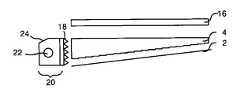
Translated fromKorean도 1은 종래의 백라이트유닛의 구성을 나타내는 도면.1 is a view showing the configuration of a conventional backlight unit.
도 2는 종래의 양각패턴을 갖는 도광판을 이용한 백라이트유닛을 나타내는 도면.2 is a view showing a backlight unit using a light guide plate having a conventional relief pattern.
도 3은 종래의 집광시트를 이용한 백라이트 유닛을 나타내는 도면.3 is a view showing a backlight unit using a conventional light collecting sheet.
도 4는 종래의 프리즘호일을 이용한 백라이트 유닛을 나타내는 도면.4 is a view showing a backlight unit using a conventional prism foil.
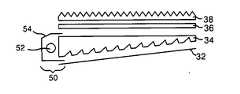
도 5는 본 발명의 제1 실시예에 따른 백라이트 유닛을 나타내는 도면.5 is a diagram illustrating a backlight unit according to a first embodiment of the present invention;
도 6은 도 5에 도시된 도광판을 나타내는 사시도.FIG. 6 is a perspective view illustrating the light guide plate illustrated in FIG. 5. FIG.
도 7은 도 6에 도시된 음각패턴을 나타내는 도면.FIG. 7 is a diagram illustrating an intaglio pattern illustrated in FIG. 6.
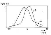
도 8은 도 5에 도시된 백라이트 유닛의 광방향분포를 나타내는 도면.FIG. 8 is a diagram illustrating a light direction distribution of the backlight unit illustrated in FIG. 5.
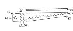
도 9는 본 발명의 제2 실시 예에 따른 백라이트 유닛을 나타내는 도면.9 illustrates a backlight unit according to a second embodiment of the present invention.
도 10은 도 9에 도시된 집광자를 나타내는 도면.FIG. 10 is a view showing a light collector shown in FIG. 9; FIG.
도 11은 도 9에 도시된 백라이트 유닛의 광방향분포를 나타내는 도면.FIG. 11 is a view illustrating a light direction distribution of the backlight unit illustrated in FIG. 9.
도 12는 본 발명의 제3 실시 예에 따른 백라이트 유닛을 나타내는 도면.12 illustrates a backlight unit according to a third embodiment of the present invention.
도 13은 도 12에 도시된 프리즘시트가 제거된 백라이트 유닛을 나타내는 도면.FIG. 13 is a view illustrating a backlight unit from which a prism sheet shown in FIG. 12 is removed.
도 14a 및 도 14b는 도 12 및 도 13에 도시된 백라이트 유닛의 광방향분포를 나타내는 도면.14A and 14B illustrate light direction distributions of the backlight unit illustrated in FIGS. 12 and 13.
도 15는 본 발명의 제4 실시 예에 따른 백라이트 유닛을 나타내는 도면.15 illustrates a backlight unit according to a fourth embodiment of the present invention.
도 16은 도 15에 도시된 발광다이오드램프의 특성을 나타내는 도면.FIG. 16 is a view showing characteristics of the light emitting diode lamp shown in FIG. 15;
도 17은 본 발명의 제5 실시 예에 따른 백라이트 유닛을 나타내는 도면.17 illustrates a backlight unit according to a fifth embodiment of the present invention.
도 18은 본 발명의 제6 실시 예에 따른 백라이트 유닛을 나타내는 도면.18 illustrates a backlight unit according to a sixth embodiment of the present invention.
도 19는 본 발명의 제7 실시 예에 따른 백라이트 유닛을 나타내는 도면.
19 illustrates a backlight unit according to a seventh embodiment of the present invention.
< 도면의 주요 부분에 대한 부호의 설명 ><Description of Symbols for Main Parts of Drawings>
2,32 : 반사판4,34 : 도광판2,32:
6,36 : 확산시트8,10,38 : 프리즘시트6,36:
16 : 집광시트18 : 집광호일16: condensing sheet 18: condensing foil
20,50 : 입광부22,52 : 램프20,50
24,54 : 램프하우징40 : 반사부24,54: lamp housing 40: reflector
56a,56b : 집광자60 : 도광판의 하면56a, 56b: condenser 60: lower surface of light guide plate
62 : 발광다이오드램프
62: light emitting diode lamp
본 발명은 백라이트 유닛에 관한 것으로, 특히 고집광이 가능함과 동시에 비용을 절감할 수 있는 백라이트유닛에 관한 것이다.The present invention relates to a backlight unit, and more particularly, to a backlight unit capable of high light condensing and reducing costs.
통상적으로, 액정표시장치(Liquid Crystal Display; 이하 "LCD"라 함)는 매트릭스 형태로 배열되어진 다수의 액정셀들과 이들 액정셀들 각각에 공급될 비디오 신호를 절환하기 위한 다수의 제어용 스위치들로 구성된 액정패널에 의해 백라이트 유닛(Back Light Unit)에서 공급되는 광빔의 투과량이 조절되어 화면에 원하는 화상을 표시하게 된다. 이하, 도 1 및 도 2를 결부하여 백라이트 유닛에 대하여 살펴보기로 한다.Typically, a liquid crystal display (hereinafter referred to as "LCD") is a plurality of liquid crystal cells arranged in a matrix form and a plurality of control switches for switching the video signal to be supplied to each of these liquid crystal cells The transmission amount of the light beam supplied from the backlight unit is adjusted by the configured liquid crystal panel to display a desired image on the screen. Hereinafter, the backlight unit will be described with reference to FIGS. 1 and 2.
도 1을 참조하면, 종래의 백라이트 유닛은 입광부(20)를 경유한 광빔을 안내하는 도광판(4)과, 도광판(4)의 하부에 위치하여 도광판(4)의 하면 및 측면으로 진행하는 광빔을 상면쪽으로 반사시키는 반사판(2)과, 도광판(4)을 경유한 광빔을 확산시키는 제1 확산시트(6)와, 제1 확산시트(6)를 경유한 광빔의 진행방향을 조절하는 제1 및 제2 프리즘시트(8,10)와, 프리즘시트(8,10)를 경유한 광빔을 확산시키고 프리즘시트를 보호하는 제2 확산시트(12)를 구비한다. 입광부(20)는 광빔을 발생하는 램프(22)와, 램프(22)를 실장함과 아울러 램프(22)의 광빔을 도광판(4)으로 반사시키는 램프하우징(24)으로 구성된다.Referring to FIG. 1, a conventional backlight unit includes a
램프(22)는 주로 냉음극형광램프가 사용되고 있으며, 램프(22)에서 발생되는 광은 도광판(4)의 측면에 존재하는 입사면을 통해 도광판(4)에 입사된다. 램프 하우징(24)은 내면에 반사면이 있어 램프(22)로부터의 광을 도광판(4)의 입사면쪽으로 반사시킨다. 도광판(4)은 램프(22)로부터 입사된 광이 램프(2)와 거리가 먼 곳 까지 광이 도달되도록 한다. 도광판(4)의 하면에는 반사판(2)이 대면되도록 설치된다. 반사판(2)은 도광판(4)의 배면을 통해 자신에게 입사되는 광을 도광판(4) 쪽으로 재반사시킴으로써 광손실을 줄이는 역할을 한다. 도광판(4)의 하면에 형성된 인쇄식 패턴이 마련되어 입광부를 경유한 광빔이 경사면인 배면에서 소정 경사각으로 반사되어 출사면쪽으로 균일하게 진행하게 된다. 이때, 도광판(4)의 하면 및 측면으로 진행한 광은 반사판(2)에 반사되어 출사면쪽으로 진행하게 된다. 도광판(4)을 경유하여 출사된 광은 제1 확산시트(6)에 의해 전영역으로 확산되게 된다. 한편, 액정패널(도시되지않음)에 입사되는 광은 수직을 이룰 때 광효율이 커지게 된다. 이를 위해, 도광판(4)에서 출사된 광의 진행각도를 액정패널과 수직을 이루도록 정방향 프리즘시트를 2매 적층하는 것이 바람직하다. 제1 및 제2 프리즘시트(8,10)를 경유한 광은 제2 확산시트(12)를 경유하여 액정패널에 입사되게 된다. 상기와 같은 구성을 갖는 종래의 백라이트 유닛은 프리즘시트 2매가 반드시 포함되어야만 원하는 시야각 프로파일을 얻을수 있게 된다. 이 경우, 광손실이 증가함과 아울러 제조비용이 상승하는 문제점이 있다. 이러한, 문제를 해결하기 위해 제안된 구조가 도 2에 도시되어 있다. 이하, 도 2를 결부하여 이에 대하여 살펴보기로 한다.The
도 2를 참조하면, 종래의 백라이트 유닛은 입광부(20)를 경유한 광빔을 안내하는 도광판(4)과, 도광판(4)의 하부에 위치하여 도광판(4)의 하면 및 측면으로 진행하는 광빔을 상면쪽으로 반사시키는 반사판(2)과, 도광판(4)을 경유한 광빔의 진행방향을 조절하는 역방향 프리즘시트(14)와, 역방향 프리즘시트(14)를 경유한 광 빔을 확산시키는 확산시트(12)를 구비한다. 입광부(20) 및 반사판(2)의 기능 및 동작은 도 1에서 충분히 설명하였으므로 상세한 설명은 생략하기로 한다. 도광판(4)의 하면에는 양각의 프리즘패턴이 마련되어 입광부(20)를 경유한 광빔의 전반사 조건이 만족하지 않도록 하여 광빔이 균일하게 상면쪽으로 진행되도록 한다. 도광판(4)의 상부에는 역방향 프리즘시트(14)를 배치하게 된다. 이 경우, 도광판(4)에서 출사되는 광빔의 각도가 약 65°이상 이므로 프리즘시트(14)의 꼭지각은 63 - 70°를 유지하는 것이 바람직하다. 이에 따라, 프리즘시트(14)를 경유한 광빔이 액정패널과 수직을 이루게 된다. 프리즘시트(14)를 경유한 광빔은 확산시트(12)에 의해 전영역으로 확산되어 진행하게 된다. 상기와 같은 구성을 갖는 종래의 백라이트유닛은 역방향 프리즘시트(14)를 사용함에 의해 도광판(4)의 벽면 비침 또는 입광부(20)의 휘선이 보이는 문제점이 있다.Referring to FIG. 2, the conventional backlight unit includes a
이에 따라, 벽면비침 및 입광부 휘선을 최소화 할 수 있는 고집광용 백라이트 유닛이 절실히 요구되고 있는 실정이다.Accordingly, there is an urgent need for a high condensing backlight unit capable of minimizing wall reflection and light incident portion.
이러한 고집광용 백라이트 유닛은 도 3 및 도 4에 도시된 바와 같이 집광효율이 좋은 집광시트(16)를 이용하여 집광하는 방법이다.The high condensing backlight unit is a method of condensing using the
도 3에 도시된 고집광용 백라이트 유닛은 도광판(4)의 하면에 양각패턴이 마련되어 있어 도 1에 도시된 프리즘시트(10,8) 및 확산판(6,12)의 역할을 하게 된다. 이러한 도광판(4)을 경유한 광빔이 집광시트(16)를 통과함으로써 집광효율이 향상된다.In the high light collecting backlight unit illustrated in FIG. 3, an embossed pattern is provided on a lower surface of the
도 4에 도시된 고집광용 백라이트 유닛은 도광판(4)의 하면에 양각패턴이 형 성됨과 아울러 입광부(20)의 출사영역에 프리즘호일(18)이 형성되어 램프(22)에서 출사되는 광을 집광하게 된다.In the high-condensation backlight unit shown in FIG. 4, an embossed pattern is formed on the lower surface of the
그러나, 도 3 및 도 4에 도시된 집광시트(16)는 항공 및 군사용의 특수목적의 디스플레이의 경우에만 사용될만큼 고가여서 범용적으로 사용되지 못하는 문제점이 있다. 또한, 도 4에 도시된 고집광용 백라이트 유닛은 프리즘호일(18)이 형성된 영역만큼 부피가 커지는 문제점이 있다.
However, the
따라서, 본 발명의 목적은 고집광이 가능함과 동시에 비용을 절감할 수 있는 백라이트유닛을 제공하는데 있다.
Accordingly, an object of the present invention is to provide a backlight unit capable of high light condensing and at the same time reducing the cost.
상기 목적을 달성하기 위하여 본 발명에 따른 백라이트유닛은 광을 발생하는 광원과, 광원을 감싸는 형태로 설치되어 광을 반사시키는 램프하우징과, 하면에 소정간격을 두고 소정깊이를 가지는 다수의 음각패턴이 형성된 도광판을 구비하며, 도광판의 출사면으로 향하는 상기 음각패턴의 꼭지각은 30~95°인 것을 특징으로 한다.In order to achieve the above object, the backlight unit according to the present invention includes a light source for generating light, a lamp housing installed to surround the light source, and reflecting light, and a plurality of intaglio patterns having a predetermined depth on a lower surface thereof. It is provided with a light guide plate, the vertex angle of the intaglio pattern toward the exit surface of the light guide plate is characterized in that 30 ~ 95 °.
상기 백라이트 유닛은 도광판을 경유한 광빔을 확산시키는 확산시트와, 확산시트를 경유한 광빔의 진행방향을 조절하는 프리즘시트를 추가로 구비하는 것을 특징으로 한다.The backlight unit may further include a diffusion sheet for diffusing the light beam through the light guide plate, and a prism sheet for adjusting the traveling direction of the light beam through the diffusion sheet.
상기 소정간격은 음각패턴이 광원과 가까울수록 상대적으로 넓게, 광원과 멀어질수록 상대적으로 좁게 형성되는 것을 특징으로 한다.The predetermined interval may be relatively wider as the intaglio pattern is closer to the light source, and relatively narrower as it is farther from the light source.
상기 소정깊이는 표시패널의 크기에 따라 도광판의 하면으로부터 수㎛~수십㎛로 식각되는 것을 특징으로 한다.The predetermined depth may be etched from several micrometers to several tens of micrometers from the lower surface of the light guide plate according to the size of the display panel.
상기 음각패턴은 도광판의 입사면에서 수㎜내의 거리를 두고 형성되는 것을 특징으로 한다.The intaglio pattern is formed at a distance of several mm from the incident surface of the light guide plate.
상기 음각패턴의 피치는 도광판의 입사면에 대면되는 측면영역쪽에 위치할수록 상대적으로 작게 형성되며, 그 이외의 영역쪽에 위치할수록 상대적으로 크게 형성되는 것을 특징으로 한다.The pitch of the intaglio pattern is relatively small as it is located toward the side region facing the incident surface of the light guide plate, and is characterized in that it is formed relatively larger as it is located besides the other region.
상기 음각패턴은 삼각형 형태로 형성되어 상기 피치에 대하여 제1 및 제2 경사각이 형성되며, 제1 경사각은 약 25~60°, 제2 경사각은 약 60~90°로 형성되는 것을 특징으로 한다.The intaglio pattern is formed in a triangular shape to form a first and second inclination angle with respect to the pitch, the first inclination angle is about 25 ~ 60 °, the second inclination angle is characterized in that formed about 60 ~ 90 °.
상기 제1 경사각은 약 46~50°, 제2 경사각은 약 78~82°로 형성되는 것을 특징으로 한다.The first inclination angle is about 46 ~ 50 °, the second inclination angle is characterized in that formed in about 78 ~ 82 °.
상기 백라이트 유닛은 광원과 도광판의 입사면 사이에는 광을 집광하기 위해 프리즘 패턴의 집광자가 적어도 하나 이상 형성되는 것을 특징으로 한다.The backlight unit is characterized in that at least one light collector of the prism pattern is formed between the light source and the incident surface of the light guide plate to collect light.
상기 집광자는 폴리메틸메타아크릴레이트(Polymethyl Methacrylate ; PMMA)로 형성되는 것을 특징으로 한다.The light collector is characterized in that it is formed of polymethyl methacrylate (PMMA).
상기 집광자는 집광자의 하면에 대하여 제1 및 제2 경사각이 형성되며, 제1 및 제2 경사각은 약 10~45°인 것을 특징으로 한다.The condenser may have first and second inclination angles formed with respect to the lower surface of the condenser, and the first and second inclination angles may be about 10 ° to about 45 °.
상기 제1 및 제2 경사각은 약 35~37°인 것을 특징으로 한다.The first and second inclination angles are about 35 to 37 degrees.
상기 도광판의 하부에는 도광판과 대면되게 형성되는 반사판을 추가로 구비하는 것을 특징으로 한다.A lower portion of the light guide plate is further provided with a reflecting plate formed to face the light guide plate.
상기 도광판 하면에는 음각패턴 상에 반사금속으로 코팅되어 형성되는 반사부를 추가로 구비하는 것을 특징으로 한다.The lower surface of the light guide plate may further include a reflector formed on the intaglio pattern by coating with a reflective metal.
상기 반사금속은 알루미늄(Al) 또는 은(Ag) 등으로 형성되는 것을 특징으로 한다.The reflective metal is formed of aluminum (Al) or silver (Ag).
상기 백라이트 유닛은 6인치 이하의 표시패널에 대응되는 것을 특징으로 한다.The backlight unit may correspond to a display panel of 6 inches or less.
상기 목적을 달성하기 위하여, 본 발명에 따른 백라이트 유닛은 소정각도 이내에서 집광되는 광을 발생하는 발광다이오드와, 하면에 소정간격을 두고 소정깊이를 가지는 다수의 음각패턴이 형성된 도광판을 구비하며, 도광판의 출사면으로 향하는 음각패턴의 꼭지각은 30~95°인 것을 특징으로 한다.In order to achieve the above object, the backlight unit according to the present invention includes a light emitting diode for generating light condensed within a predetermined angle, and a light guide plate having a plurality of intaglio patterns having a predetermined depth on a lower surface and having a predetermined depth. The vertex angle of the intaglio pattern toward the exit surface is characterized in that 30 ~ 95 °.
상기 소정간격은 음각패턴이 발광다이오드와 가까울수록 상대적으로 넓게, 발광다이오드와 멀어질수록 상대적으로 좁게 형성되는 것을 특징으로 한다.The predetermined interval may be relatively wider as the intaglio pattern is closer to the light emitting diode and relatively narrower as it is farther from the light emitting diode.
상기 소정깊이는 표시패널의 크기에 따라 도광판의 하면으로부터 수㎛~수십㎛로 식각되는 것을 특징으로 한다.The predetermined depth may be etched from several micrometers to several tens of micrometers from the lower surface of the light guide plate according to the size of the display panel.
상기 음각패턴은 도광판의 입사면에서 수㎜내의 거리를 두고 형성되는 것을 특징으로 한다.The intaglio pattern is formed at a distance of several mm from the incident surface of the light guide plate.
상기 음각패턴의 피치는 도광판의 입사면에 대면되는 측면영역쪽에 위치할수 록 상대적으로 작게 형성되며, 그 이외의 영역쪽에 위치할수록 상대적으로 크게 형성되는 것을 특징으로 한다.The pitch of the intaglio pattern is relatively small to be located in the side region side facing the incident surface of the light guide plate, it is characterized in that it is formed relatively larger as the other side.
상기 음각패턴은 삼각형 형태로 형성되어 피치에 대하여 제1 및 제2 경사각이 형성되며, 제1 경사각은 약 25~60°, 제2 경사각은 약 60~90°로 형성되는 것을 특징으로 한다.The intaglio pattern is formed in a triangular shape, the first and second inclination angles are formed with respect to the pitch, the first inclination angle is about 25 ~ 60 °, the second inclination angle is characterized in that formed about 60 ~ 90 °.
상기 백라이트 유닛은 발광다이오드와 도광판의 입사면 사이에는 광을 집광하기 위해 프리즘 패턴의 집광자가 적어도 하나 이상 형성되는 것을 특징으로 한다.The backlight unit is characterized in that at least one light collector of the prism pattern is formed between the light emitting diode and the incident surface of the light guide plate to collect light.
상기 도광판의 하부에는 도광판과 대면되게 형성되는 반사판을 추가로 구비하는 것을 특징으로 한다.A lower portion of the light guide plate is further provided with a reflecting plate formed to face the light guide plate.
상기 도광판 하면에는 음각패턴 상에 반사금속으로 코팅되어 형성되는 반사부를 추가로 구비하는 것을 특징으로 한다.The lower surface of the light guide plate may further include a reflector formed on the intaglio pattern by coating with a reflective metal.
상기 반사금속은 알루미늄(Al) 또는 은(Ag) 등으로 형성되는 것을 특징으로 한다.The reflective metal is formed of aluminum (Al) or silver (Ag).
상기 백라이트 유닛은 6인치 이하의 표시패널에 대응되는 것을 특징으로 한다.The backlight unit may correspond to a display panel of 6 inches or less.
상기 목적을 달성하기 위하여, 본 발명의 다른 실시 예에 따른 백라이트 유닛은 소정각도 이내에서 집광되는 광을 발생하는 발광다이오드와, 발광다이오드로부터의 광을 출사면을 통하여 표시패널로 입사시키는 도광판과, 도광판의 하부에 위치하여 도광판의 하면 및 측면으로 진행하는 광빔을 상면쪽으로 반사시키는 반사 판과, 도광판을 경유한 광빔을 확산시키는 확산시트와, 확산시트를 경유한 광빔의 진행방향을 조절하는 프리즘시트를 구비하는 것을 특징으로 한다.In order to achieve the above object, a backlight unit according to another embodiment of the present invention is a light emitting diode for generating light collected within a predetermined angle, a light guide plate for injecting light from the light emitting diode to the display panel through the emission surface; A reflection plate positioned at the lower part of the light guide plate to reflect the light beams traveling to the lower surface and the side surface of the light guide plate toward the upper surface; a diffusion sheet for diffusing the light beam through the light guide plate; Characterized in having a.
상기 소정각도는 발광다이오드의 곡률에 의해 결정되는 것을 특징으로 한다.The predetermined angle is characterized by the curvature of the light emitting diode.
상기 목적 외에 본 발명의 다른 목적 및 특징들은 첨부도면을 참조한 실시예에 대한 설명을 통하여 명백하게 드러나게 될 것이다.Other objects and features of the present invention in addition to the above objects will become apparent from the description of the embodiments with reference to the accompanying drawings.
도 5 내지 도 19를 참조하여 본 발명의 바람직한 실시 예에 대하여 설명하기로 한다.A preferred embodiment of the present invention will be described with reference to FIGS. 5 to 19.
도 5를 참조하면, 본 발명의 제1 실시예에 따른 백라이트유닛은 입광부(50)를 경유한 광빔을 안내하는 도광판(34)과, 도광판(34)의 하부에 위치하여 도광판(34)의 하면 및 측면으로 진행하는 광빔을 상면쪽으로 반사시키는 반사판(32)과, 도광판(34)을 경유한 광빔을 확산시키는 확산시트(36)와, 확산시트(36)를 경유한 광빔의 진행방향을 조절하는 프리즘시트(38)를 구비한다.Referring to FIG. 5, the backlight unit according to the first exemplary embodiment of the present invention may include a
입광부(50)는 광빔을 발생하는 램프(52)와, 램프(52)를 실장함과 아울러 램프(52)의 광빔을 도광판(34)으로 반사시키는 램프하우징(54)으로 구성된다.The
램프(52)는 주로 냉음극형광램프가 사용되고 있으며, 램프(52)에서 발생되는 광은 도광판(34)의 측면에 존재하는 입사면을 통해 도광판(34)에 입사된다. 램프 하우징(54)은 내면에 반사면이 있어 램프(52)로부터의 광을 도광판(34)의 입사면쪽으로 반사시킨다.The
도광판(34)의 배면에는 반사판(32)이 대면되도록 설치된다. 반사판(32)은 도광판(34)의 배면을 통해 자신에게 입사되는 광을 도광판(34)쪽으로 재반사시킴으 써 광손실을 줄이는 역할을 한다.The rear side of the
도광판(34)은 램프(52)로부터 입사된 광이 램프(52)와 거리가 먼 곳까지 광이 도달되도록 한다.The
도광판(34)의 하면은 도 6에 도시된 바와 같이 소정각도로 기울어지게 형성되며, 음각패턴(A)이 다수개 형성된다. 다수의 음각패턴(A)은 입광부(50)를 경유한 광빔의 진행방향을 수직으로 진행시키게 된다. 이 음각패턴(A)의 깊이 및 간격 등을 조정함으로써 화상이 개선된다.As shown in FIG. 6, the lower surface of the
이를 상세히 설명하면, 다수의 음각패턴(A)들은 도 7에 도시된 바와 같이 도광판(34)의 하면(60)에서 소정의 깊이(h)만큼 식각된 삼각형 형상으로 형성되어 제1 경사면(L1)과 제2 경사면(L2)을 갖게 된다. 이 때, 깊이(h)는 액정패널의 크기에 따라 수㎛~수십㎛범위에서 조절하여 표시품질을 개선할 수 있다. 또한, 도광판(34)의 하면(60)과 제1 경사면(L1)과의 사이각(α)은 25~60°로, 도광판(34)의 하면(60)과 제2 경사면(L2)과의 사이각(β)은 60~90°의 범위로 설정되어 도광판의 출사면으로 향하는 꼭지점(42)의 꼭지각은 30~95°로 설정된다. 바람직하게는 도광판(34)의 하면(60)과 제1 경사면(L1)과의 사이각(α)이 46~50°로, 도광판(34)의 하면(60)과 제2 경사면(L2)과의 사이각(β)은 78~82°의 범위로 설정된다.In detail, a plurality of intaglio patterns A are formed in a triangular shape etched by a predetermined depth h on the
광빔의 균일도를 확보하기 위해 음각패턴(A)의 간격(y)이 조절된다. 실제로, 입광부(50)와 가까울수록 음각패턴(A)의 간격(y)은 넓게 설정되고, 입광부(50)와 멀어질수록 음각패턴(A)의 간격(y)은 좁게 설정되는 것이 바람직하다.The spacing y of the intaglio pattern A is adjusted to secure the uniformity of the light beam. In fact, it is preferable that the distance y of the intaglio pattern A is set wider as it is closer to the
도광판(34)에 형성되는 음각패턴(A)은 도광판(34)의 입사면에서 소정간격(d) 을 사이에 두고 시작점(s)이 형성된다. 이 시작점(s)이 입사면과 가까울수록 음각패턴(A)의 깊이(h)는 작아지고, 입사면과 멀어질수록 음각패턴(A)의 깊이(h)는 커진다. 시작점(s)이 입사면에 가까울수록 입광부(50) 부근에서 발생되는 암선 등이 제거되기 때문에, 음각패턴(A)은 도광판(34)의 입사면에서 수㎜내에서 시작되어야 한다.In the intaglio pattern A formed on the
음각패턴(A) 간의 피치(p)는 음각패턴(A)이 형성되는 위치에 따라 다르게 형성된다. 도광판(34)의 입사면과 가까운 쪽에 위치하는 음각패턴(A)의 피치(p)는 상대적으로 작게 형성되고, 그 이외의 영역인 입사반대면과 중간영역쪽에 위치하는 음각패턴(A)의 피치(p)는 상대적으로 크게 형성된다.The pitch p between the intaglio patterns A is formed differently according to the position where the intaglio patterns A are formed. The pitch p of the intaglio pattern A located on the side closer to the incident surface of the
도 8은 본 발명의 제1 실시 예에 따른 도광판(34)으로부터 출사되어진 광방향 분포를 나타내는 도면이다. 도 8의 가로축은 시야각을, 세로축은 빛의 세기를 각각 나타낸다. 도광판(34)에서 출사되는 광빔의 상하시야각(A) 및 좌우시야각(B)은 도 8에 도시된 바와 같이 각각 종래에 비해 수직 및 수평방향으로 집광되게 된다. 이러한 구조를 갖는 도광판(34)을 사용할 경우 프리즘시트(38)를 종래에 2매에서 1매로 줄일 수 있어 비용을 절감할 수 있다. 또한, 프리즘시트(38)에 의한 광손실을 방지하게 되어 광효율이 향상된다.FIG. 8 is a diagram illustrating a light direction distribution emitted from the
도 9는 본 발명의 제2 실시 예에 따른 백라이트를 나타내는 도면이며, 도 10은 도 9에 도시된 집광자를 나타내는 도면이다.FIG. 9 is a view illustrating a backlight according to a second embodiment of the present invention, and FIG. 10 is a view illustrating a light collector shown in FIG. 9.
도 9 및 도 10을 참조하면, 본 발명의 제2 실시 예에 따른 백라이트 유닛은 도 5에 도시된 백라이트 유닛과 비교하여 프리즘(38) 시트 대신에 입광부(50)에 집광자(56a,56b)를 형성하는 것을 제외하고는 동일한 구성요소를 구비한다.9 and 10, the backlight unit according to the second exemplary embodiment of the present invention collects
입광부(50)는 광을 발생하는 램프(52)와, 램프(52)를 감싸는 형태로 설치되는 램프하우징(54)과, 광을 집광시키는 제1 및 제2 집광자(56a,56b)를 구비한다.The
램프(52)는 주로 냉음극형광램프가 사용되며, 램프(52)에서 발생되는 광은 제1 집광자(56a)에 입사된다. 램프 하우징(54)은 내면에 반사면이 있어 램프(52)로부터의 광을 제1 집광자(56a)쪽으로 반사시킨다.The
제1 및 제2 집광자(56a,56b)는 다수의 프리즘패턴으로 형성되어 광을 집광시키는 역할을 한다. 또한, 제1 및 제2 집광자(56a,56b)는 램프(52)와 도광판(34) 사이에 형성되어 램프(52)와 도광판(34) 사이의 틈새로 일어나는 광손실을 줄일 수 있다. 즉, 제1 및 제2 집광자(56a,56b)는 램프(52)에서 발생된 광과 램프 하우징(54)에 의해 반사된 광을 집광한다. 이와 같이, 제1 및 제2 집광자(56a,56b)에 의해 집광된 광은 도광판(34)에 입사된다.The first and
이러한 제1 및 제2 집광자(56a,56b)의 제1 및 제2 사이각(γ1,γ2)은 도 10에 도시된 바와 같이 10~45°로 형성된다. 바람직하게는 제1 및 제2 사이각(γ1,γ2)이 35~37°일 때, 광이 최대로 집광된다. 제1 및 제2 집광자(56a,56b)는 강도가 높아 쉽게 변형되거나 깨지지 않으며 투과율이 좋은 아크릴수지 등으로 형성된다. 예를 들어, 제1 및 제2 집광자(56a,56b)는 폴리메틸메타아크릴레이트(Polymethyl Methacrylate ; PMMA)로 형성된다.The first and second angles γ1 and γ2 of the first and
도 11은 본 발명의 제2 실시 예에 따른 도광판(34)으로부터 출사되어진 광방향 분포를 나타내는 도면이다. 도 11의 가로축은 시야각을, 세로축은 빛의 세기를 각각 나타낸다. 도광판(34)에서 출사되는 광빔의 상하시야각(A) 및 좌우시야각(B) 은 각각 종래에 비해 수직 및 수평방향으로 집광되게 된다. 이에 따라, 종래의 2매로 형성된 프리즘시트를 형성하지 않고서 제1 및 제2 집광자(56a,56b)와 도광판(34)으로도 기존의 광특성을 나타낼 수 있다. 종래의 제1 및 제2 프리즘시트를 형성하지 않아도 됨으로써 비용을 절감할 수 있다.FIG. 11 is a diagram illustrating a light direction distribution emitted from the
도 12는 본 발명의 제3 실시 예에 따른 백라이트를 나타내는 도면이다.12 is a diagram illustrating a backlight according to a third embodiment of the present invention.
도 12를 참조하면, 본 발명의 제3 실시 예에 따른 백라이트 유닛은 도 5에 도시된 백라이트 유닛과 비교하여 반사판 대신에 도광판(34) 하부에 금속이 코팅된 반사부(40)가 형성되는 것을 제외하고는 동일한 구성요소를 구비한다.Referring to FIG. 12, in the backlight unit according to the third embodiment of the present invention, a reflector 40 coated with a metal is formed below the
반사부(40)는 다수의 음각패턴이 형성된 도광판(34) 하면에 반사금속을 코팅하게 된다. 반사부(40)는 반사금속인 은(Ag), 알루미늄(Al) 등으로 형성된다. 이러한 반사부(40)를 갖는 백라이트 유닛은 6인치이하의 액정표시장치에 적용된다.The reflector 40 coats the reflective metal on the lower surface of the
반사부(40)는 도광판(34)의 하면을 통해 자신에게 입사되는 광을 도광판(34) 쪽으로 재반사시킴으로써 광손실을 줄이는 역할을 한다.The reflector 40 serves to reduce light loss by reflecting light incident to itself through the lower surface of the
도광판(34) 상부에는 도광판(34)을 경유한 광빔을 확산시키는 확산시트(36)와, 확산시트(36)를 경유한 광빔의 진행방향을 조절하는 프리즘시트(38)가 형성된다.A
도광판(34) 상부에 형성되는 프리즘시트(38)를 도 13에 도시된 바와 같이 제거하여도 백라이트 유닛은 동일한 효과를 얻는다. 이를 도 14a 및 도 14b를 참조하여 상세히 설명하기로 한다.Even if the
도 14a 및 도 14b는 각각 도 12 및 도 13에 도시된 백라이트 유닛으로부터 출사되어진 광방향 분포를 나타내는 도면이다. 도 14a 및 도 14b의 가로축은 시야각을, 세로축은 빛의 세기를 각각 나타낸다. 도 14a에 도시된 백라이트 유닛에서 출사되는 광빔의 상하시야각(A) 및 좌우시야각(B)은 각각 종래에 비해 수직 및 수평방향으로 집광되게 된다. 도 14b에 도시된 백라이트 유닛에서 출사되는 광빔의 분포는 도 14a에 도시된 백라이트 유닛과 거의 유사하다. 이에 따라, 종래의 2매로 형성된 프리즘시트를 1매만 형성하게 되고, 반사판을 형성하지 않고서도 기존의 광특성을 나타낼 수 있다. 또한, 프리즘시트와 반사판을 형성하지 않아도 됨으로써 비용을 절감할 수 있다.14A and 14B are diagrams illustrating light direction distributions emitted from the backlight unit illustrated in FIGS. 12 and 13, respectively. 14A and 14B, the horizontal axis represents the viewing angle, and the vertical axis represents the light intensity, respectively. The vertical and horizontal viewing angles (A) and the left and right viewing angles (B) of the light beams emitted from the backlight unit illustrated in FIG. 14A are focused in the vertical and horizontal directions, respectively. The distribution of light beams emitted from the backlight unit shown in FIG. 14B is almost similar to the backlight unit shown in FIG. 14A. As a result, only one prism sheet formed of two conventional sheets is formed, and existing optical characteristics can be exhibited without forming a reflecting plate. In addition, since the prism sheet and the reflection plate do not need to be formed, the cost can be reduced.
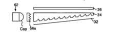
도 15는 본 발명의 제4 실시 예에 따른 백라이트 유닛은 광을 생성하는 발광다이오드램프(62)와, 발광다이오드램프(62)에서 생성된 광을 안내하는 도광판(34)과, 도광판(34)의 하부에 위치하여 도광판(34)의 하면 및 측면으로 진행하는 광빔을 상면쪽으로 반사시키는 반사판(32)과, 도광판(34)을 경유한 광빔을 확산시키는 확산시트(36)와, 확산시트(36)를 경유한 광빔의 진행방향을 조절하는 프리즘시트(38)를 구비한다.15 illustrates a light emitting
발광다이오드(Light-Emitting Diode ; 이하"LED"라 함)램프(62)는 R,G,B의 3색광을 만들 수 있어 광원으로 사용된다. 이 LED램프(62)에서 생성된 광은 특정 방향성을 갖고 있어서, LED램프(62)에서는 도 16에 도시된 바와 같이 방사패턴을 가지고 있다. 이 방사패턴은 LED램프(62)의 곡률(cap)에 따라 결정된다. 이 방사패턴이 좁아질수록 광은 특정한 방향에 집광된다. 바람직하게는 광분포를 0~±30°정도가 되도록 곡률(cap)를 제어하게 된다. 이러한 LED램프(62)에서 고집광된 광은 도광판(34)의 측면에 존재하는 입사면을 통해 도광판(34)에 입사된다. 도광판(34)은 LED램프(62)로부터 입사된 광을 LED램프(62)와 거리가 먼 곳까지 광이 도달되도록 한다. 도광판(34)의 하면에는 반사판(32)이 대면되도록 설치된다. 반사판(32)은 도광판(34)의 배면을 통해 자신에게 입사되는 광을 도광판(34) 쪽으로 재반사시킴으로써 광손실을 줄이는 역할을 한다. 도광판(34)의 하면에 인쇄식 패턴이 마련되어 LED램프(62)에서 생성된 광빔이 경사면인 하면에서 소정 경사각으로 반사되어 출사면쪽으로 균일하게 진행하게 된다. 이때, 도광판(34)의 하면 및 측면으로 진행한 광은 반사판(32)에 반사되어 출사면쪽으로 진행하게 된다. 도광판(34)을 경유하여 출사된 광은 확산시트(36)에 의해 전영역으로 확산되게 된다. 한편, 액정패널(도시되지않음)에 입사되는 광은 수직을 이룰 때 광효율이 커지게 된다. 이를 위해, 도광판(34)에서 출사된 광의 진행각도를 액정패널과 수직을 이루도록 프리즘시트(38)를 형성하게 된다. 프리즘시트(38)를 경유한 광은 액정패널에 입사된다.The light-emitting diode (LED)
이와 같이, 본 발명의 제4 실시 예에 따른 백라이트 유닛은 LED램프(62)를 사용함으로써 광이 고집광되어 광손실을 억제할 수 있다. 또한, 한 매로 줄어든 프리즘시트(38)로 인해 비용을 절감할 수 있다.As described above, in the backlight unit according to the fourth exemplary embodiment of the present invention, the light is concentrated by using the
도 17은 본 발명의 제5 실시 예에 따른 백라이트 유닛을 나타내는 도면이다.17 is a diagram illustrating a backlight unit according to a fifth embodiment of the present invention.
도 17을 참조하면, 본 발명의 제5 실시 예에 따른 백라이트 유닛은 도 5에 도시된 백라이트 유닛과 비교하여 입광부의 램프 대신에 LED램프(62)가 형성되는 것을 제외하고는 동일한 구성요소를 구비한다.Referring to FIG. 17, the backlight unit according to the fifth exemplary embodiment of the present invention includes the same components as the backlight unit illustrated in FIG. 5 except that the
LED램프(62)는 광을 특정한 방향으로 집광하는 성질을 가지고 있다. 이에 따라, 광분포가 ±30°정도가 되도록 LED램프(62)의 곡률(cap)를 제어하게 된다. 이러한 LED램프(62)에서 고집광된 광은 도광판(34)의 측면에 존재하는 입사면을 통해 도광판(34)에 입사된다.The
도광판(34)의 배면에는 반사판(32)이 대면되도록 설치된다. 반사판(32)은 도광판(34)의 배면을 통해 자신에게 입사되는 광을 도광판(34) 쪽으로 재반사시킴으로써 광손실을 줄이는 역할을 한다.The rear side of the
도광판(34)은 LED램프(62)로부터 입사된 광이 LED램프(62)와 거리가 먼 곳까지 광이 도달되도록 한다.The
도광판(34)의 하면은 도 6 및 도 7에 전술한 바와 같이 소정각도로 기울어지게 형성되며, 음각패턴(A)이 다수개 형성된다. 다수의 음각패턴(A)들은 도광판(34)의 하면(60)에서 액정패널의 크기에 따라 수㎛~수십㎛의 깊이(h)만큼 식각된 삼각형 형상으로 제1 경사면(L1)과 제2 경사면(L2)을 갖게 된다.The lower surface of the
도광판(34)의 하면(60)과 제1 경사면(L1)과의 사이각(α)은 25~60°로, 도광판(34)의 하면(60)과 제2 경사면(L2)과의 사이각(β)은 60~90°로, 도광판의 출사면으로 향하는 음각패턴의 꼭지각은 30~95°의 범위로 설정한다. 바람직하게는 도광판(34)의 하면(60)과 제1 경사면과의 사이각(α)이 46~50°로, 도광판(34)의 하면(60)과 제2 경사면(L2)과의 사이각(β)은 78~82°의 범위로 설정된다.The angle α between the
광빔의 균일도를 확보하기 위해 입광부(50)와 가까울수록 음각패턴(A)의 간격(y)은 넓게 설정되고, 입광부(50)와 멀어질수록 음각패턴(A)의 간격(y)은 좁게 설정되는 것이 바람직하다.In order to secure the uniformity of the light beam, the distance y of the intaglio pattern A is set wider as it is closer to the
도광판(34)에 형성되는 음각패턴(A)의 시작점(s)이 앞단에 가까울수록 입광부(50) 부근에서 발생되는 암선 등이 제거되기 때문에, 음각패턴(A)은 도광판(34)의 앞단에서 수㎜내에서 시작되어야 한다.As the starting point s of the intaglio pattern A formed on the
도광판(34)의 입사면과 가까운 쪽에 위치하는 음각패턴(A)의 피치(p)는 상대적으로 작게 형성되고, 그 이외의 영역에 위치하는 음각패턴(A)의 피치(p)는 상대적으로 크게 형성된다.The pitch p of the intaglio pattern A positioned near the incident surface of the
이와 같이, 본 발명의 제5 실시 예에 따른 백라이트 유닛은 LED램프(62)를 사용함으로써 광이 고집광되어 광손실을 억제할 수 있다. 또한, 프리즘시트(38)를 제거할 수 있으므로 비용을 절감할 수 있다.As described above, in the backlight unit according to the fifth exemplary embodiment of the present invention, the light is highly condensed by using the
도 18은 본 발명의 제6 실시 예에 따른 백라이트 유닛을 나타내는 도면이다.18 is a diagram illustrating a backlight unit according to a sixth embodiment of the present invention.
도 18을 참조하면, 본 발명의 제6 실시 예에 따른 백라이트 유닛은 도 9에 도시된 백라이트 유닛과 비교하여 입광부(50)의 램프(52) 대신에 LED램프(62)가 형성되는 것을 제외하고는 동일한 구성요소를 구비한다.Referring to FIG. 18, the backlight unit according to the sixth exemplary embodiment of the present invention except that the
LED램프(62)는 광을 특정한 방향에 집광하는 성질을 가지고 있다. 이에 따라, 광분포가 ±30°정도가 되도록 LED램프(62)의 곡률(cap)를 제어하게 된다. 이러한 LED램프(62)에서 고집광된 광은 집광자(56a)에 입사된다.The
집광자(56a)는 다수의 프리즘패턴으로 형성되어 광을 집광시키는 역할을 한다. 또한, 집광자(56a)는 LED램프(62)와 도광판(34) 사이에 형성되어 LED램프(62)와 도광판(34) 사이의 틈새로 일어나는 광손실을 줄일 수 있다. 즉, 집광자(56a)는 LED램프(62)에서 발생된 광을 집광한다. 이와 같이, 집광자(56a)에 의해 집광된 광은 도광판(34)의 측면에 존재하는 입사면을 통해 도광판(34)에 입사된다.The
이러한 집광자(56a)의 제1 및 제2 사이각(γ1,γ2)은 도 10에 도시된 바와 같이 10~45°로 형성된다. 바람직하게는 제1 및 제2 사이각(γ1,γ2)이 35~37°일 때, 광이 최대로 집광된다. 집광자(56a)는 강도가 높아 쉽게 변형되거나 깨지지 않으며 투과율이 좋은 아크릴수지 등으로 형성된다. 예를 들어, 집광자(56)는 폴리메틸메타아크릴레이트(Polymethyl Methacrylate ; PMMA)로 형성된다.The first and second angles γ1 and γ2 of the
이와 같이, 본 발명의 제6 실시 예에 따른 백라이트 유닛은 LED램프(62)와 집광자(56a)를 사용함으로써 광이 고집광되어 광손실을 억제할 수 있다. 또한, 프리즘시트(38)를 제거할 수 있으므로 비용을 절감할 수 있다.As described above, the backlight unit according to the sixth embodiment of the present invention uses the
도 19는 본 발명의 제7 실시 예에 따른 백라이트 유닛을 나타내는 도면이다.19 is a diagram illustrating a backlight unit according to a seventh embodiment of the present invention.
도 19를 참조하면, 본 발명의 제7 실시 예에 따른 백라이트 유닛은 도 12에 도시된 백라이트 유닛과 비교하여 입광부(50)의 램프(52) 대신에 LED램프(62)가 형성되는 것을 제외하고는 동일한 구성요소를 구비한다.Referring to FIG. 19, the backlight unit according to the seventh exemplary embodiment of the present invention except that the
LED램프(62)는 광을 특정한 방향에 집광하는 성질을 가지고 있다. 이에 따라, 광분포가 ±30°정도가 되도록 LED램프(62)의 곡률(cap)를 제어하게 된다. 이러한 LED램프(62)에서 고집광된 광은 도광판에 입사된다.The
도광판(34)의 배면에는 반사부(40)가 형성된다. 반사부(40)는 도광판(34)의 배면을 통해 자신에게 입사되는 광을 도광판(34) 쪽으로 재반사시킴으로써 광손실을 줄이는 역할을 한다.The reflector 40 is formed on the rear surface of the
반사부(40)는 다수의 음각패턴이 형성된 도광판(34) 하면에 반사금속을 코팅 하게 된다. 반사부(40)는 반사금속인 은(Ag), 알루미늄(Al) 등으로 형성된다. 이러한 반사부(40)를 갖는 백라이트 유닛은 6인치이하의 액정표시장치에 적용된다.The reflector 40 coats the reflective metal on the bottom surface of the
도광판(34) 상부에는 도광판(34)을 경유한 광빔을 확산시키는 확산시트(36)가 형성된다.A
이와 같이, 본 발명의 제7 실시 예에 따른 백라이트 유닛은 LED램프(62)와 반사부를 사용함으로써 광이 고집광되어 광손실을 억제할 수 있다. 또한, 반사판과 프리즘 시트를 사용하지 않고도 집광된 광분포를 얻을 수 있어 비용을 절감할 수 있다.As described above, in the backlight unit according to the seventh exemplary embodiment, the light is highly concentrated by using the
본 발명의 제1 내지 제7 실시 예에 따른 백라이트 유닛은 CLC(Cholesteric Liquid Crystal) 칼라필터를 이용한 디스플레이에 적용하여 집광효과를 얻을 수 있다. 즉, 종래의 고색순도 및 고휘도를 얻기 위해 CLC 칼라필터를 이용한 투과형 액정표시장치는 본 발명의 제1 내지 제7 실시 예에 따른 백라이트 유닛을 이용함으로써 시야각에 따른 컬러 쉬프트 문제를 해결할 수 있다.The backlight units according to the first to seventh embodiments of the present invention may be applied to a display using a CLC (Cholesteric Liquid Crystal) color filter to obtain a light collecting effect. That is, the conventional liquid crystal display using the CLC color filter to obtain high color purity and high brightness can solve the color shift problem according to the viewing angle by using the backlight units according to the first to seventh embodiments of the present invention.
본 발명의 제1 내지 제7 실시 예에 따른 백라이트 유닛의 도광판은 입사면과 입사면과 대면되는 측면의 길이가 다른 웨지형으로 형성된다. 이 웨지형은 입사면과 측면의 길이가 같은 평판형보다 백라이트의 무게가 적으며, 경사진 영역에 액정표시장치의 다른 부품등을 장착할 수 있어 전체적인 액정표시장치의 부피를 줄일 수 있다.
The light guide plates of the backlight units according to the first to seventh embodiments of the present invention are formed in a wedge shape having different lengths of incidence surfaces and side surfaces facing the incidence surfaces. This wedge type has a lower weight of the backlight than a flat type having the same side length as the incident surface, and it is possible to mount other parts of the liquid crystal display in an inclined area, thereby reducing the volume of the entire liquid crystal display.
상술한 바와같이, 본 발명에 따른 백라이트 유닛은 도광판의 하면에 음각패턴이 형성된다. 이 음각패턴의 간격 및 깊이 등을 조절함으로써 빛의 방향을 조정하게 된다. 이에 따라, 다양한 크기의 표시패널에 적용함과 동시에 화상이 개선된다. 또한, 프리즘시트 또는 확산시트를 제거할 수 있어 비용을 절감할 수 있다. 뿐만 아니라, 종래의 입광부에 사용된 냉음극형광램프대신에 발광다이오드를 이용한다. 이 발광다이오드의 곡률를 제어하여 발광다이오드에서 출사되어지는 광이 소정 각도내에서 집광되도록 한다. 이에 따라, 고집광된 광을 얻을 수 있다. As described above, in the backlight unit according to the present invention, an intaglio pattern is formed on the lower surface of the light guide plate. The direction of light is adjusted by adjusting the interval and depth of the intaglio pattern. Accordingly, the image is improved while being applied to display panels of various sizes. In addition, the prism sheet or the diffusion sheet can be removed, thereby reducing the cost. In addition, a light emitting diode is used in place of the cold cathode fluorescent lamp used in the conventional light receiving unit. The curvature of the light emitting diode is controlled so that the light emitted from the light emitting diode is focused within a predetermined angle. Thereby, highly condensed light can be obtained.
이상 설명한 내용을 통해 당업자 라면 본 발명의 기술사상을 일탈하지 아니하는 범위에서 다양한 변경 및 수정이 가능함을 알수 있을 것이다. 따라서, 본 발명의 기술적 범위는 명세서의 상세한 설명에 기재된 내용으로 한정되는 것이 아니라 특허 청구의 범위에 의해 정하여 져야만 할 것이다.Those skilled in the art will appreciate that various changes and modifications can be made without departing from the technical spirit of the present invention. Therefore, the technical scope of the present invention should not be limited to the contents described in the detailed description of the specification but should be defined by the claims.
Claims (28)
Translated fromKoreanPriority Applications (2)
| Application Number | Priority Date | Filing Date | Title |
|---|---|---|---|
| KR1020010084074AKR100835005B1 (en) | 2001-12-24 | 2001-12-24 | Backlight unit |
| US10/325,973US7104679B2 (en) | 2001-12-24 | 2002-12-23 | Backlight unit |
Applications Claiming Priority (1)
| Application Number | Priority Date | Filing Date | Title |
|---|---|---|---|
| KR1020010084074AKR100835005B1 (en) | 2001-12-24 | 2001-12-24 | Backlight unit |
Publications (2)
| Publication Number | Publication Date |
|---|---|
| KR20030055368A KR20030055368A (en) | 2003-07-04 |
| KR100835005B1true KR100835005B1 (en) | 2008-06-04 |
Family
ID=19717496
Family Applications (1)
| Application Number | Title | Priority Date | Filing Date |
|---|---|---|---|
| KR1020010084074AExpired - Fee RelatedKR100835005B1 (en) | 2001-12-24 | 2001-12-24 | Backlight unit |
Country Status (2)
| Country | Link |
|---|---|
| US (1) | US7104679B2 (en) |
| KR (1) | KR100835005B1 (en) |
Families Citing this family (57)
| Publication number | Priority date | Publication date | Assignee | Title |
|---|---|---|---|---|
| KR100539461B1 (en)* | 2002-06-28 | 2006-01-16 | 주식회사 엘 앤 에프 | Prismatic backlight device and manufacturing method thereof |
| US7520635B2 (en) | 2003-07-02 | 2009-04-21 | S.C. Johnson & Son, Inc. | Structures for color changing light devices |
| US7484860B2 (en) | 2003-07-02 | 2009-02-03 | S.C. Johnson & Son, Inc. | Combination white light and colored LED light device with active ingredient emission |
| US7476002B2 (en) | 2003-07-02 | 2009-01-13 | S.C. Johnson & Son, Inc. | Color changing light devices with active ingredient and sound emission for mood enhancement |
| US7318659B2 (en) | 2004-03-03 | 2008-01-15 | S. C. Johnson & Son, Inc. | Combination white light and colored LED light device with active ingredient emission |
| US7604378B2 (en) | 2003-07-02 | 2009-10-20 | S.C. Johnson & Son, Inc. | Color changing outdoor lights with active ingredient and sound emission |
| JP2005138686A (en)* | 2003-11-05 | 2005-06-02 | Kyowa Sangyo Kk | Vehicle sun visor |
| JP4379786B2 (en)* | 2003-11-11 | 2009-12-09 | 株式会社エンプラス | Surface light source device |
| AU2005219978B2 (en) | 2004-03-03 | 2010-08-26 | S.C. Johnson & Son, Inc. | LED light bulb with active ingredient emission |
| US7503675B2 (en) | 2004-03-03 | 2009-03-17 | S.C. Johnson & Son, Inc. | Combination light device with insect control ingredient emission |
| JP4535792B2 (en)* | 2004-07-01 | 2010-09-01 | Nec液晶テクノロジー株式会社 | Backlight and liquid crystal display device including the backlight |
| TWI296343B (en)* | 2004-07-16 | 2008-05-01 | Hon Hai Prec Ind Co Ltd | Light guide plate and backlight system |
| CN100403110C (en)* | 2004-08-31 | 2008-07-16 | 鸿富锦精密工业(深圳)有限公司 | Light guide board |
| JP2006156332A (en)* | 2004-10-28 | 2006-06-15 | Alps Electric Co Ltd | Light guide plate, surface light emitting device using the same, and liquid crystal display device using the same |
| JP2006138975A (en)* | 2004-11-11 | 2006-06-01 | Nec Lcd Technologies Ltd | Backlight and liquid crystal display device |
| KR20060089020A (en)* | 2005-02-03 | 2006-08-08 | 삼성전자주식회사 | Back light assembly and display device having same |
| EP1847767A4 (en)* | 2005-02-08 | 2013-01-23 | Fujifilm Corp | Light guide plate, and planar lighting device and liquid crystal display device using such light guide plate |
| JP4741866B2 (en)* | 2005-03-28 | 2011-08-10 | Nec液晶テクノロジー株式会社 | Light source device, display device using the same, and terminal device |
| JP2006344598A (en)* | 2005-06-10 | 2006-12-21 | Samsung Electronics Co Ltd | Light guide plate, backlight assembly having the same, and liquid crystal display device |
| KR101158524B1 (en)* | 2005-07-18 | 2012-06-21 | 에스엘 주식회사 | Light guide plate with scattering pattern |
| US7366393B2 (en)* | 2006-01-13 | 2008-04-29 | Optical Research Associates | Light enhancing structures with three or more arrays of elongate features |
| US20070086207A1 (en)* | 2006-01-13 | 2007-04-19 | Optical Research Associates | Display systems including light enhancing structures with arrays of elongate features |
| US7545569B2 (en) | 2006-01-13 | 2009-06-09 | Avery Dennison Corporation | Optical apparatus with flipped compound prism structures |
| US7866871B2 (en)* | 2006-01-13 | 2011-01-11 | Avery Dennison Corporation | Light enhancing structures with a plurality of arrays of elongate features |
| US7674028B2 (en)* | 2006-01-13 | 2010-03-09 | Avery Dennison Corporation | Light enhancing structures with multiple arrays of elongate features of varying characteristics |
| JP2007220347A (en)* | 2006-02-14 | 2007-08-30 | Citizen Electronics Co Ltd | Variable prism light guide plate |
| JP4491466B2 (en)* | 2006-07-31 | 2010-06-30 | エプソンイメージングデバイス株式会社 | Electro-optical device, electronic equipment |
| KR100790499B1 (en)* | 2006-10-12 | 2008-01-02 | 희성전자 주식회사 | Side Dimming Backlight Unit |
| KR101604243B1 (en)* | 2007-12-31 | 2016-03-18 | 삼성디스플레이 주식회사 | Light guide plate, backlight unit and liquid crystal display having the same |
| KR101421628B1 (en)* | 2008-01-11 | 2014-07-24 | 삼성디스플레이 주식회사 | Back light assembly |
| US20090214828A1 (en)* | 2008-02-26 | 2009-08-27 | Vicki Herzl Watkins | Blunt tip prism film and methods for making the same |
| US7639918B2 (en)* | 2008-05-05 | 2009-12-29 | Visteon Global Technologies, Inc. | Manifold-type lightguide with reduced thickness |
| KR100977750B1 (en)* | 2008-07-16 | 2010-08-27 | 엘지전자 주식회사 | Lighting Apparatus for Refrigerator |
| GB0813608D0 (en)* | 2008-07-25 | 2008-09-03 | L T G W Ltd | Vehicle number plate |
| KR20100095812A (en)* | 2009-02-23 | 2010-09-01 | 삼성전자주식회사 | Back light unit and liquid crystal display comprising the same |
| US20110044582A1 (en) | 2009-08-21 | 2011-02-24 | Microsoft Corporation | Efficient collimation of light with optical wedge |
| US8354806B2 (en)* | 2009-08-21 | 2013-01-15 | Microsoft Corporation | Scanning collimation of light via flat panel lamp |
| KR101039608B1 (en)* | 2010-05-04 | 2011-06-09 | 엘지이노텍 주식회사 | Backlight Unit and Display Device |
| US9201185B2 (en) | 2011-02-04 | 2015-12-01 | Microsoft Technology Licensing, Llc | Directional backlighting for display panels |
| WO2012148928A2 (en)* | 2011-04-26 | 2012-11-01 | Inteled Corporation | Product lighting refrigeration door |
| US20130027772A1 (en) | 2011-07-27 | 2013-01-31 | Microsoft Corporation | Variable-depth stereoscopic display |
| US9303204B2 (en)* | 2011-11-30 | 2016-04-05 | Chin Piao Kuo | Planar light source device and method of manufacturing same |
| US9354748B2 (en) | 2012-02-13 | 2016-05-31 | Microsoft Technology Licensing, Llc | Optical stylus interaction |
| US8873227B2 (en) | 2012-03-02 | 2014-10-28 | Microsoft Corporation | Flexible hinge support layer |
| US9075566B2 (en) | 2012-03-02 | 2015-07-07 | Microsoft Technoogy Licensing, LLC | Flexible hinge spine |
| US9870066B2 (en) | 2012-03-02 | 2018-01-16 | Microsoft Technology Licensing, Llc | Method of manufacturing an input device |
| US9460029B2 (en) | 2012-03-02 | 2016-10-04 | Microsoft Technology Licensing, Llc | Pressure sensitive keys |
| TWI539211B (en)* | 2012-04-30 | 2016-06-21 | 中強光電股份有限公司 | Light guide plate and backlight module using the same |
| US20130300590A1 (en) | 2012-05-14 | 2013-11-14 | Paul Henry Dietz | Audio Feedback |
| US8947353B2 (en) | 2012-06-12 | 2015-02-03 | Microsoft Corporation | Photosensor array gesture detection |
| US9256089B2 (en) | 2012-06-15 | 2016-02-09 | Microsoft Technology Licensing, Llc | Object-detecting backlight unit |
| US8964379B2 (en) | 2012-08-20 | 2015-02-24 | Microsoft Corporation | Switchable magnetic lock |
| US9552777B2 (en) | 2013-05-10 | 2017-01-24 | Microsoft Technology Licensing, Llc | Phase control backlight |
| CN103605211B (en)* | 2013-11-27 | 2016-04-20 | 南京大学 | Tablet non-auxiliary stereo display device and method |
| US10120420B2 (en) | 2014-03-21 | 2018-11-06 | Microsoft Technology Licensing, Llc | Lockable display and techniques enabling use of lockable displays |
| US10324733B2 (en) | 2014-07-30 | 2019-06-18 | Microsoft Technology Licensing, Llc | Shutdown notifications |
| JP6981090B2 (en)* | 2017-08-09 | 2021-12-15 | 大日本印刷株式会社 | Light guide plate, surface light source device and display device |
Citations (6)
| Publication number | Priority date | Publication date | Assignee | Title |
|---|---|---|---|---|
| KR19990029518A (en)* | 1997-09-08 | 1999-04-26 | 이주미 마사노리 | Surface light source element and display device using same |
| JPH11264974A (en)* | 1998-03-17 | 1999-09-28 | Nitto Denko Corp | Surface light source device, polarizing surface light source device, and liquid crystal display device |
| KR20000016302U (en)* | 1999-01-29 | 2000-08-25 | 김순택 | Back light for liquid crystal display |
| KR20010016745A (en)* | 1999-08-03 | 2001-03-05 | 윤종용 | Liquid crystal display device and method for improving brightness |
| KR20010043054A (en)* | 1998-04-30 | 2001-05-25 | 나카노 가츠히코 | Light guide plate |
| KR20010091505A (en)* | 2000-03-16 | 2001-10-23 | 윤종용 | LCD and manufacturing method for light guiding plate used for LCD |
Family Cites Families (8)
| Publication number | Priority date | Publication date | Assignee | Title |
|---|---|---|---|---|
| JPH06314069A (en)* | 1993-03-03 | 1994-11-08 | Fujitsu Ltd | Lighting equipment |
| US6123431A (en)* | 1997-03-19 | 2000-09-26 | Sanyo Electric Co., Ltd | Backlight apparatus and light guide plate |
| TW422346U (en)* | 1998-11-17 | 2001-02-11 | Ind Tech Res Inst | A reflector device with arc diffusion uint |
| US6827456B2 (en)* | 1999-02-23 | 2004-12-07 | Solid State Opto Limited | Transreflectors, transreflector systems and displays and methods of making transreflectors |
| JP4741142B2 (en)* | 2000-01-06 | 2011-08-03 | コーニンクレッカ フィリップス エレクトロニクス エヌ ヴィ | Lighting device and light emitting panel |
| JP4006918B2 (en)* | 2000-02-28 | 2007-11-14 | オムロン株式会社 | Surface light source device and manufacturing method thereof |
| KR100514011B1 (en)* | 2000-07-24 | 2005-09-13 | 미츠비시 레이온 가부시키가이샤 | Surface illuminant device and prism sheet used therefor |
| US6648485B1 (en)* | 2000-11-13 | 2003-11-18 | International Business Machines Corporation | Highly collimating tapered light guide for uniform illumination of flat panel displays |
- 2001
- 2001-12-24KRKR1020010084074Apatent/KR100835005B1/ennot_activeExpired - Fee Related
- 2002
- 2002-12-23USUS10/325,973patent/US7104679B2/ennot_activeExpired - Lifetime
Patent Citations (6)
| Publication number | Priority date | Publication date | Assignee | Title |
|---|---|---|---|---|
| KR19990029518A (en)* | 1997-09-08 | 1999-04-26 | 이주미 마사노리 | Surface light source element and display device using same |
| JPH11264974A (en)* | 1998-03-17 | 1999-09-28 | Nitto Denko Corp | Surface light source device, polarizing surface light source device, and liquid crystal display device |
| KR20010043054A (en)* | 1998-04-30 | 2001-05-25 | 나카노 가츠히코 | Light guide plate |
| KR20000016302U (en)* | 1999-01-29 | 2000-08-25 | 김순택 | Back light for liquid crystal display |
| KR20010016745A (en)* | 1999-08-03 | 2001-03-05 | 윤종용 | Liquid crystal display device and method for improving brightness |
| KR20010091505A (en)* | 2000-03-16 | 2001-10-23 | 윤종용 | LCD and manufacturing method for light guiding plate used for LCD |
Also Published As
| Publication number | Publication date |
|---|---|
| US7104679B2 (en) | 2006-09-12 |
| US20030117793A1 (en) | 2003-06-26 |
| KR20030055368A (en) | 2003-07-04 |
Similar Documents
| Publication | Publication Date | Title |
|---|---|---|
| KR100835005B1 (en) | Backlight unit | |
| KR100679094B1 (en) | Backlight unit | |
| KR100942490B1 (en) | LGP having a front surface with an optical member and a liquid crystal display using the same | |
| JP4209870B2 (en) | Direct backlight module | |
| JPH0894844A (en) | Light guide plate, surface light source using the same, and non-emissive display device | |
| KR20040063385A (en) | Backlight unit | |
| CN101178513A (en) | backlight unit | |
| TW200905306A (en) | Backlight module and liquid crystal display comprising the same | |
| KR101165460B1 (en) | backlight unit of liquid crystal display | |
| KR100438524B1 (en) | BackLight Unit | |
| JP2001143515A (en) | Prism sheet and surface light source element | |
| JPH07159607A (en) | Optical control sheet and surface light emitting device provided therewith | |
| KR100879948B1 (en) | Side Dimming Backlight Device Using Micro Rectangular Lens Pattern | |
| JP4147776B2 (en) | Backlight for LCD | |
| KR100736075B1 (en) | LGP of the backlight unit | |
| JP3411858B2 (en) | Light guide plate and flat lighting device | |
| JP4349741B2 (en) | Illumination device having a light guide plate | |
| KR100911463B1 (en) | Surface light source device | |
| KR100880938B1 (en) | Backlight unit | |
| CN100367090C (en) | Direct Type Backlight Assembly | |
| KR20070001495A (en) | Backlight unit | |
| KR100845250B1 (en) | Backlight unit | |
| KR100634554B1 (en) | Backlight unit | |
| KR100936819B1 (en) | Backlight unit | |
| KR20050070457A (en) | Back light assembly |
Legal Events
| Date | Code | Title | Description |
|---|---|---|---|
| PA0109 | Patent application | St.27 status event code:A-0-1-A10-A12-nap-PA0109 | |
| PG1501 | Laying open of application | St.27 status event code:A-1-1-Q10-Q12-nap-PG1501 | |
| A201 | Request for examination | ||
| P11-X000 | Amendment of application requested | St.27 status event code:A-2-2-P10-P11-nap-X000 | |
| P13-X000 | Application amended | St.27 status event code:A-2-2-P10-P13-nap-X000 | |
| PA0201 | Request for examination | St.27 status event code:A-1-2-D10-D11-exm-PA0201 | |
| D13-X000 | Search requested | St.27 status event code:A-1-2-D10-D13-srh-X000 | |
| D14-X000 | Search report completed | St.27 status event code:A-1-2-D10-D14-srh-X000 | |
| R17-X000 | Change to representative recorded | St.27 status event code:A-3-3-R10-R17-oth-X000 | |
| E902 | Notification of reason for refusal | ||
| PE0902 | Notice of grounds for rejection | St.27 status event code:A-1-2-D10-D21-exm-PE0902 | |
| E13-X000 | Pre-grant limitation requested | St.27 status event code:A-2-3-E10-E13-lim-X000 | |
| P11-X000 | Amendment of application requested | St.27 status event code:A-2-2-P10-P11-nap-X000 | |
| P13-X000 | Application amended | St.27 status event code:A-2-2-P10-P13-nap-X000 | |
| E701 | Decision to grant or registration of patent right | ||
| PE0701 | Decision of registration | St.27 status event code:A-1-2-D10-D22-exm-PE0701 | |
| PN2301 | Change of applicant | St.27 status event code:A-3-3-R10-R13-asn-PN2301 St.27 status event code:A-3-3-R10-R11-asn-PN2301 | |
| GRNT | Written decision to grant | ||
| PR0701 | Registration of establishment | St.27 status event code:A-2-4-F10-F11-exm-PR0701 | |
| PR1002 | Payment of registration fee | St.27 status event code:A-2-2-U10-U11-oth-PR1002 Fee payment year number:1 | |
| PG1601 | Publication of registration | St.27 status event code:A-4-4-Q10-Q13-nap-PG1601 | |
| R18-X000 | Changes to party contact information recorded | St.27 status event code:A-5-5-R10-R18-oth-X000 | |
| PR1001 | Payment of annual fee | St.27 status event code:A-4-4-U10-U11-oth-PR1001 Fee payment year number:4 | |
| R18-X000 | Changes to party contact information recorded | St.27 status event code:A-5-5-R10-R18-oth-X000 | |
| R18-X000 | Changes to party contact information recorded | St.27 status event code:A-5-5-R10-R18-oth-X000 | |
| FPAY | Annual fee payment | Payment date:20120330 Year of fee payment:5 | |
| PR1001 | Payment of annual fee | St.27 status event code:A-4-4-U10-U11-oth-PR1001 Fee payment year number:5 | |
| FPAY | Annual fee payment | Payment date:20130329 Year of fee payment:6 | |
| PR1001 | Payment of annual fee | St.27 status event code:A-4-4-U10-U11-oth-PR1001 Fee payment year number:6 | |
| PR1001 | Payment of annual fee | St.27 status event code:A-4-4-U10-U11-oth-PR1001 Fee payment year number:7 | |
| FPAY | Annual fee payment | Payment date:20150429 Year of fee payment:8 | |
| PR1001 | Payment of annual fee | St.27 status event code:A-4-4-U10-U11-oth-PR1001 Fee payment year number:8 | |
| FPAY | Annual fee payment | Payment date:20160428 Year of fee payment:9 | |
| PR1001 | Payment of annual fee | St.27 status event code:A-4-4-U10-U11-oth-PR1001 Fee payment year number:9 | |
| FPAY | Annual fee payment | Payment date:20170413 Year of fee payment:10 | |
| PR1001 | Payment of annual fee | St.27 status event code:A-4-4-U10-U11-oth-PR1001 Fee payment year number:10 | |
| FPAY | Annual fee payment | Payment date:20180416 Year of fee payment:11 | |
| PR1001 | Payment of annual fee | St.27 status event code:A-4-4-U10-U11-oth-PR1001 Fee payment year number:11 | |
| FPAY | Annual fee payment | Payment date:20190417 Year of fee payment:12 | |
| PR1001 | Payment of annual fee | St.27 status event code:A-4-4-U10-U11-oth-PR1001 Fee payment year number:12 | |
| PC1903 | Unpaid annual fee | St.27 status event code:A-4-4-U10-U13-oth-PC1903 Not in force date:20200529 Payment event data comment text:Termination Category : DEFAULT_OF_REGISTRATION_FEE | |
| PC1903 | Unpaid annual fee | St.27 status event code:N-4-6-H10-H13-oth-PC1903 Ip right cessation event data comment text:Termination Category : DEFAULT_OF_REGISTRATION_FEE Not in force date:20200529 |