KR100834633B1 - Keypad combination structure of mobile terminal - Google Patents
Keypad combination structure of mobile terminalDownload PDFInfo
- Publication number
- KR100834633B1 KR100834633B1KR1020060108884AKR20060108884AKR100834633B1KR 100834633 B1KR100834633 B1KR 100834633B1KR 1020060108884 AKR1020060108884 AKR 1020060108884AKR 20060108884 AKR20060108884 AKR 20060108884AKR 100834633 B1KR100834633 B1KR 100834633B1
- Authority
- KR
- South Korea
- Prior art keywords
- keypad
- front case
- hook
- coupled
- rubber
- Prior art date
- Legal status (The legal status is an assumption and is not a legal conclusion. Google has not performed a legal analysis and makes no representation as to the accuracy of the status listed.)
- Expired - Fee Related
Links
Images


Classifications
- H—ELECTRICITY
- H01—ELECTRIC ELEMENTS
- H01H—ELECTRIC SWITCHES; RELAYS; SELECTORS; EMERGENCY PROTECTIVE DEVICES
- H01H13/00—Switches having rectilinearly-movable operating part or parts adapted for pushing or pulling in one direction only, e.g. push-button switch
- H01H13/70—Switches having rectilinearly-movable operating part or parts adapted for pushing or pulling in one direction only, e.g. push-button switch having a plurality of operating members associated with different sets of contacts, e.g. keyboard
- H01H13/702—Switches having rectilinearly-movable operating part or parts adapted for pushing or pulling in one direction only, e.g. push-button switch having a plurality of operating members associated with different sets of contacts, e.g. keyboard with contacts carried by or formed from layers in a multilayer structure, e.g. membrane switches
- H01H13/705—Switches having rectilinearly-movable operating part or parts adapted for pushing or pulling in one direction only, e.g. push-button switch having a plurality of operating members associated with different sets of contacts, e.g. keyboard with contacts carried by or formed from layers in a multilayer structure, e.g. membrane switches characterised by construction, mounting or arrangement of operating parts, e.g. push-buttons or keys
- H—ELECTRICITY
- H04—ELECTRIC COMMUNICATION TECHNIQUE
- H04B—TRANSMISSION
- H04B1/00—Details of transmission systems, not covered by a single one of groups H04B3/00 - H04B13/00; Details of transmission systems not characterised by the medium used for transmission
- H04B1/38—Transceivers, i.e. devices in which transmitter and receiver form a structural unit and in which at least one part is used for functions of transmitting and receiving
- H—ELECTRICITY
- H01—ELECTRIC ELEMENTS
- H01H—ELECTRIC SWITCHES; RELAYS; SELECTORS; EMERGENCY PROTECTIVE DEVICES
- H01H2221/00—Actuators
- H01H2221/09—Flexible integral part of housing
- H—ELECTRICITY
- H01—ELECTRIC ELEMENTS
- H01H—ELECTRIC SWITCHES; RELAYS; SELECTORS; EMERGENCY PROTECTIVE DEVICES
- H01H2223/00—Casings
- H01H2223/01—Mounting on appliance
- H01H2223/014—Mounting on appliance located in recess
- H—ELECTRICITY
- H01—ELECTRIC ELEMENTS
- H01H—ELECTRIC SWITCHES; RELAYS; SELECTORS; EMERGENCY PROTECTIVE DEVICES
- H01H2229/00—Manufacturing
- H01H2229/022—Modular assembly
Landscapes
- Engineering & Computer Science (AREA)
- Computer Networks & Wireless Communication (AREA)
- Signal Processing (AREA)
- Telephone Set Structure (AREA)
- Push-Button Switches (AREA)
Abstract
Translated fromKoreanDescription
Translated fromKorean도 1은 종래의 휴대 단말기 중에서 바-형 휴대 단말기의 키패드를 나타낸 사시도,1 is a perspective view showing a keypad of a bar-type portable terminal of the conventional portable terminal,
도 2는 도 1의 키패드의 결합 상태를 나타낸 측단면도.Figure 2 is a side cross-sectional view showing a coupling state of the keypad of Figure 1;
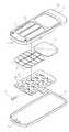
도 3은 본 발명의 일 실시예에 따른 휴대 단말기의 키패드 결합 구조의 구성을 나타낸 분해사시도.Figure 3 is an exploded perspective view showing the configuration of the keypad combination structure of a mobile terminal according to an embodiment of the present invention.
도 4는 본 발명의 일 실시예에 따른 휴대 단말기의 키패드 결합 구조의 결합과정을 나타낸 사시도.Figure 4 is a perspective view showing a coupling process of the keypad coupling structure of the mobile terminal according to an embodiment of the present invention.
도 5는 본 발명의 일 실시예에 따른 휴대 단말기의 키패드 결합 구조의 결합된 상태를 나타낸 사시도.Figure 5 is a perspective view showing a combined state of the keypad coupling structure of the mobile terminal according to an embodiment of the present invention.
도 6은 도 5의 A-A' 선단면도를 나타낸 도면으로서. 휴대 단말기의 키패드 결합 구조의 구성을 나타낸 분해도.FIG. 6 is a sectional view taken along the line AA ′ of FIG. 5; FIG. Exploded view showing the structure of a keypad combining structure of a mobile terminal.
도 7은 도 5의 A-A' 선단면도.7 is a cross-sectional view taken along the line A-A 'of FIG.
도 8은 도 7의 A부 확대 측단면도.FIG. 8 is an enlarged side sectional view of portion A of FIG. 7; FIG.
도 9는 도 7의 A부 확대 측단면도로서, 휴대 단말기의 키패드 결합 구조의 작동된 상태를 나타낸 측단면도.FIG. 9 is an enlarged side cross-sectional view of portion A of FIG. 7, and is a side cross-sectional view showing an activated state of a keypad coupling structure of the portable terminal.
본 발명은 휴대 단말기의 키패드 결합 구조에 관한 것으로 특히, 휴대 단말기의 프론트 케이스의 상면에 적층으로 결합되는 키패드부를 구성한 휴대 단말기의 키패드 결합 구조에 관한 것이다.The present invention relates to a keypad coupling structure of a portable terminal, and more particularly, to a keypad coupling structure of a portable terminal including a keypad portion coupled to a top surface of a front case of the portable terminal in a stack.
통상적으로, "휴대용 통신 장치"라 함은 사용자가 휴대하면서 상대방과 무선통신을 수행할 수 있는 장치를 의미한다. 이러한 휴대용 통신 장치로는 HHP, CT-2 셀룰라 폰, 디지털 폰, PCS 폰 및 PDA등를 칭하며, 외형상으로 여러 타입으로 분류된다. 예를 들어, 무선 단말기는 외형에 따라 바-형(bar-type), 플립-형(flip-type) 또는 폴더-형(folder-type) 무선 단말기로 분류된다. 상기 열거한 종래의 휴대용 단말기들은 필수적으로 안테나 장치, 데이터 입출력 장치, 데이터 송수신 장치를 구비하게 된다. 물론, 상기 데이터 입력장치는 주로 손가락 누름 동작으로 데이터 입력할 수 있는 키패드가 보편적으로 사용된다.In general, the term “portable communication device” refers to a device that a user can carry and perform wireless communication with a counterpart. Such portable communication devices are referred to as HHP, CT-2 cellular phones, digital phones, PCS phones and PDAs, and are classified into various types in appearance. For example, wireless terminals are classified into bar-type, flip-type, or folder-type wireless terminals according to their appearance. The above-mentioned conventional portable terminals essentially have an antenna device, a data input / output device, and a data transmission / reception device. Of course, the data input device is commonly used as a keypad for inputting data mainly by finger pressing.
데이터를 입력을 위해 사용되는 키패드는 다수 개의 키들의 배열로 이루어진다.The keypad used for entering data consists of an arrangement of a plurality of keys.
여기서, 키패드 및 액정표시부를 구비한 바-형 휴대 단말기의 구조를 살펴보면, 다음과 같다. 도 1과 같이, 단일 하우징(1)에 키패드(2) 및 액정표시부(3)를 구비하고, 액정표시부(3)의 상부에 스피커 장치(4)를 구비하고, 키패드(2)의 하부 에 마이크 장치(5)가 구비된다.Herein, the structure of a bar-type portable terminal including a keypad and a liquid crystal display will be described. As shown in FIG. 1, a
상기 단일 하우징(1)은 프론트 케이스(1a)와 리어 케이스(1b)로 이루어지고, 상기 마이크 장치(5)는 상기 단일 하우징(1)내에 구비되는 인쇄회로기판(6)에 납땜되어 구비된다.The
상기 인쇄회로기판(6)에는 다수의 돔 스위치(6a)가 구비된다.The printed
상기 프론트 케이스(1a)와 리어 케이스(1b)에는 상기 마이크 장치(5)를 장착하기 위한 장착공간(7)이 구비된다.The
도 2와 같이, 상기 키패드(2)는 상기 프론트 케이스(1a)에 형성된 고정용 리브(1c)에 상기 프론트 케이스(1a)의 배면으로 끼워 결합됨과 동시에 프론트 케이스(1a)에 형성된 키홀(1d)을 통해 외부로 노출된다. 이때, 상기 키패드(2)는 상기 고정용 리브(1c)에 의해 고정된다.As shown in FIG. 2, the
그러나, 종래의 키패드는 단말기내에 구비된 인쇄회로기판의 돔 스위치 위에 다수개의 키들로 이루어진 키패드와, 키 러버를 순차적으로 프론트 케이스의 배면으로 장착되는 구조이므로, 상기 다수개의 키들이 상기 프론트 케이스의 키홀에 노출되기 위해서는 키들을 삽입하여 조립해야 함으로 단말기의 두께가 커져 슬림화 및 소형화에 역행하는 문제점이 발생하였다.However, since the conventional keypad has a structure in which a keypad composed of a plurality of keys is mounted on a dome switch of a printed circuit board provided in a terminal, and a key rubber is sequentially mounted to the rear of the front case, the plurality of keys are keyholes of the front case. Since the keys must be inserted and assembled in order to be exposed, the thickness of the terminal increases, resulting in the problem of slimming and miniaturization.
또한, 키패드를 고정시키는 고정용 리브가 구비되어야 함으로 부품수가 많아 단말기의 조립공정 시간이 증가하고, 제조원가가 상승하는 단점이 있었다.In addition, the fixing ribs to fix the keypad has to be provided, the number of parts increases the assembly process time of the terminal, there was a disadvantage that the manufacturing cost increases.
따라서, 본 발명은 상기와 같은 종래의 문제점을 해결하기 위한 것으로, 본 발명의 목적은, 휴대 단말기의 프론트 케이스의 상면에 적층으로 결합되는 키패드부구성함으로써, 키패드부를 프론트 케이스의 상면에서 결합하여 키패드의 조립공정을 시간을 단축시킬 수 있도록 한 휴대 단말기의 키패드 결합 구조를 제공하는데 있다.Accordingly, the present invention is to solve the conventional problems as described above, an object of the present invention, by configuring the keypad portion coupled to the upper surface of the front case of the mobile terminal by stacking, by combining the keypad portion from the upper surface of the front case keypad It is to provide a keypad coupling structure of the portable terminal to shorten the assembly process of the.
본 발명의 다른 목적은, 휴대 단말기의 프론트 케이스의 상면에 적층으로 결합되는 키패드부를 구성함으로써, 프론트 케이스의 배면 결합시 제공되던 고정용 리브가 필요없어 단말기를 슬림화 및 소형화할 수 있도록 한 휴대 단말기의 키패드 결합 구조를 제공하는데 있다.Another object of the present invention is to configure the keypad portion coupled to the upper surface of the front case of the mobile terminal by stacking, the keypad of the mobile terminal to make the terminal slimmer and compact, without the need for fixing ribs provided when the front case is coupled back To provide a bonding structure.
본 발명의 또 다른 목적은, 휴대 단말기의 프론트 케이스의 상면에 적층으로 결합되는 키패드부를 구성함으로써, 프론트 케이스의 배면 결합시 제공되던 고정용 리브가 필요없고, 이로 인해 부품수를 줄여 제조원가를 절감할 수 있도록 한 휴대 단말기의 키패드 결합 구조를 제공하는데 있다.Still another object of the present invention is to configure the keypad portion coupled to the upper surface of the front case of the mobile terminal by stacking, eliminating the need for fixing ribs provided when the front case is coupled to the rear, thereby reducing the number of parts, thereby reducing the manufacturing cost In order to provide a keypad combining structure of a mobile terminal.
상기와 같은 목적을 달성하기 위하여 본 발명은, 휴대 단말기의 키패드 결합 구조에 있어서,In order to achieve the above object, the present invention, in the keypad combination structure of the portable terminal,
걸이부가 구비된 프론트 케이스;Front case provided with a hook;
상기 프론트 케이스의 상면에 구비되는 다수의 돔 스위치를 구비한 연성회로;A flexible circuit having a plurality of dome switches provided on an upper surface of the front case;
상기 연성회로의 상면에 구비되는 키패드 러버; 및A keypad rubber provided on an upper surface of the flexible circuit; And
상기 키패드 러버의 상면에 구비되고, 상기 걸이부에 걸려 결합됨과 아울러 누름에 따라서 눌린방향으로 이동가능하게 하고, 상기 키패드 러버와 상기 돔 스위치가 서로 접촉되어 클릭감을 제공하는 키패드부로 구성되어짐을 특징으로 한다.It is provided on the upper surface of the keypad rubber, is coupled to the hook portion and is coupled to the pressing direction in accordance with the pressing, and the keypad rubber and the dome switch is characterized in that it consists of a keypad portion for providing a feeling of click in contact with each other do.
이하에서는 첨부도면을 참조하여 본 발명의 가장 바람직한 일 실시예를 상세히 설명하기로 한다.Hereinafter, with reference to the accompanying drawings will be described in detail a preferred embodiment of the present invention.
도 3, 도 4 및 도 5와 같이, 휴대 단말기의 키패드 결합 구조(10)는 프론트 케이스(20)와, 연성회로(30)와, 키패드 러버(40)와, 키패드부(50)로 이루어져 있고, 상기 프론트 케이스(20)는 후술하는 키패드부(50)와 걸려 결합되도록 걸이부(21)가 구비되어 있으며, 상기 연성회로(30)는 다수의 돔 스위치(31)를 구비하고, 상기 키패드부(50)를 누름에 따라서 상기 키패드 러버(40)의 접촉 돌기(41)와 상기 돔 스위치(31)가 접촉되도록 상기 프론트 케이스(20)의 상면에 구비되어 있고, 상기 키패드 러버(40)는 상기 키패드부(50)를 누름에 따라서 상기 키패드 러버(40)의 접촉 돌기(41)도 함께 눌려짐과 아울러 상기 돔 스위치(31)와 접촉되도록 상기 연성회로(30)의 상면에 구비되어 있다.3, 4 and 5, the
도 6, 도 7 및 도 8과 같이, 상기 키패드부(50)는 상기 걸이부(21)에 걸려 결합됨과 아울러 누름에 따라서 눌린방향으로 이동 가능하고, 이동에 따라서 상기 키패드 러버(40)의 접촉 돌기(41)와 상기 돔 스위치(31)가 서로 접촉됨과 아울러 클릭감을 제공하도록 상기 키패드 러버(40)의 상면에 구비되어 있다.6, 7 and 8, the
도 7 및 도 8과 같이, 상기 프론트 케이스(20)의 양일단에는 상기 키패드부(50)에 형성된 후크부(51)를 삽입시킴과 아울러 상기 걸이부(21)에 걸리게 하도록 삽입부(22)가 형성되어 있고, 상기 삽입부(22)에는 상기 키패드부(50)와 결합시 상기 후크부(51)와 걸려 상기 키패드부(50)를 상기 프론크 케이스(20)에서 이탈되는 것을 방지하도록 걸이부(21)가 형성되어 있으며, 상기 삽입부(22)에는 상기 키패드부(50)를 누름에 따라서 눌린방향으로 상기 후크부(51)도 함께 이동하여 상기 키패드부(50)에 클릭감을 제공하도록 클릭 공간(22a)이 형성되어 있다.As shown in FIGS. 7 and 8, both ends of the
도 6과 같이, 상기 키패드부(50)는 상기 프론트 케이스(20)의 상면에 상기 연성회로(30) 및 상기 키패드 러버(40)를 적층으로 구비하고, 이 상태에서, 상기 키패드 러버(40)의 상면에 적층으로 결합되도록 되어 있다.As illustrated in FIG. 6, the
도 8 및 도 9와 같이, 상기 키패드부(50)의 양일단에는 상기 걸이부(21)에 끼워 결합되도록 후크부(51)가 형성되어 있고, 상기 후크부(51)의 일단에는 상기 키패드부(50)를 상기 프론트 케이스(20)의 삽입부(22)에 결합시 결합을 용이하게 하도록 곡률로 이루어져 있으며, 상기 키패드부(50)의 양일단면에는 상기 키패드부(50)를 눌려질 수 있게 지지하도록 상기 프론트 케이스(20)의 양끝단과 접촉되는 접촉면(52)이 형성되어 있다.As shown in FIGS. 8 and 9,
도 6과 같이, 상기 키패드부(50)의 상단면에는 상기 키패드부(50)를 눌질 수 있도록 다수의 누름공간(53)이 형성되어 있다.As illustrated in FIG. 6, a plurality of
상기와 같은 구성을 가지는 본 발명의 바람직한 일 실시 예에 의한 휴대 단말기의 키패드 결합 구조의 동작과정을 첨부된 도 3 내지 도 9를 참조하여 더욱 상 세히 설명하면 다음과 같다.Referring to Figures 3 to 9 attached to the operation of the keypad combination structure of the mobile terminal according to an embodiment of the present invention having the configuration as described above in detail as follows.
도 3, 도 4 및 도 5와 같이, 휴대 단말기의 키패드 결합 구조(10)는 걸이부(21)가 구비된 프론트 케이스(20)와, 연성회로(30)와, 키패드 러버(40)와, 키패드부(50)로 이루어진다. 상기 프론트 케이스(20)의 상면에 다수의 돔 스위치(31)를 구비한 상기 연성회로(30)를 구비하고, 상기 연성회로(30)의 상면에 키패드 러버(40)를 구비하고, 상기 키패드 러버(40)의 상면에 키패드부(50)를 구비한다.3, 4, and 5, the
이때, 도 6 및 도 7과 같이, 상기 프론트 케이스(20)의 걸이부(21)에 상기 키패드부(50)의 후크부(51)를 끼워 결합한다. 상기 프론트 케이스(20)의 걸이부(21)는 상기 삽입부(22)에 형성되어 있으므로, 상기 후크부(51)를 상기 삽입부(22)에 삽입함과 동시에 상기 걸이부(21)에 상기 후크부(51)가 걸려 결합된다.6 and 7, the
이 상태에서, 도 8 및 도 9와 같이, 사용자가 키패드부(50)의 상면을 누르면, 상기 키패드부(50)는 눌린방향으로 이동하고, 이때, 상기 후크부(51)도 함께 이동한다, 상기 삽입부(22)에는 상기 키패드부(50)를 누름에 따라서 눌린방향으로 상기 후크부(51)도 함께 이동하여 상기 키패드부(50)에 클릭감을 제공하는 클릭 공간(22a)이 형성되어 있으므로, 상기 후크부(51)는 상기 클릭 공간(22a)으로 이동하여 상기 키패드부(50)를 눌려진다. 상기 키패드 러버(40)도 함께 눌려지고, 상기 키패드 러버(40)에 형성된 접촉돌기(41)는 상기 돔 스위치(31)와 접촉되어 클릭감을 제공한다.In this state, as shown in FIGS. 8 and 9, when the user presses the upper surface of the
도 9와 같이, 상기 키패드부(50)를 누르면, 상기 키패드부(50)의 후크부(51)를 이동시킬 수 있게 클릭 공간(22a)이 제공되고, 상기 후크부(51)는 상기 걸이 부(21)에 의해 상기 프론트 케이스(20)에서 이탈되는 것을 방지할 수 있다.As shown in FIG. 9, when the
상기 키패드부(50)의 양일단면에는 상기 키패드부(50)를 눌려질 수 있게 지지하도록 상기 프론트 케이스(20)의 양끝단과 접촉되는 접촉면(52)이 형성된다.Both end surfaces of the
또한, 상기 키패드부(50)에는 사용자가 상기 키패드부(50)의 상면을 누를 경우 상기 키패드부(50)를 눌려질 수 있게 하는 다수의 누름 공간(53)이 형성된다.In addition, a plurality of
상기와 같이, 휴대 단말기의 프론트 케이스의 상면에 적층으로 결합되는 키패드부를 구성함으로써, 키패드부를 프론트 케이스의 상면에서 결합하여 키패드의 조립공정을 시간을 단축시킬 수 있고, 프론트 케이스의 배면 결합시 제공되던 고정용 리브가 필요없어, 단말기를 슬림화 및 소형화할 수 있다.As described above, by configuring a keypad portion coupled to the upper surface of the front case of the portable terminal in a stack, by combining the keypad portion on the upper surface of the front case can shorten the time for the assembly process of the keypad, which was provided when the rear of the front case No fixing ribs are required, making the terminal slimmer and smaller.
이상에서 설명한 본 발명의 휴대 단말기의 키패드 결합 구조는 전술한 실시 예 및 도면에 의해 한정되는 것은 아니고, 본 발명의 기술적 사상을 벗어나지 않은 범위 내에서 여러 가지 치환, 변형 및 변경이 가능함은 본 발명이 속하는 기술분야에서 통상의 지식을 가진 자에게 있어 명백할 것이다.The keypad combination structure of the mobile terminal of the present invention described above is not limited to the above-described embodiments and drawings, and various substitutions, modifications, and changes are possible within the scope without departing from the technical spirit of the present invention. It will be apparent to those of ordinary skill in the art.
예를 들어, 본 발명은 휴대가 가능한 모든 단말기에 적용할 수 있다.For example, the present invention can be applied to all portable terminals.
상술한 바와 같이 본 발명에 의한 휴대 단말기의 키패드 결합 구조에 의하 면,As described above, according to the keypad coupling structure of the mobile terminal according to the present invention,
휴대 단말기의 프론트 케이스의 상면에 적층으로 결합되는 키패드부를 구성함으로써, 키패드부를 프론트 케이스의 상면에서 결합하여 키패드의 조립공정을 시간을 단축시킬 수 있고, 프론트 케이스의 배면 결합시 제공되던 고정용 리브가 필요없어 단말기를 슬림화 및 소형화할 수 있을 뿐만 아니라, 이로 인해 부품수를 줄여 제조원가를 절감할 수 있는 효과가 있다.By constructing a keypad portion coupled to the upper surface of the front case of the mobile terminal in a stack, the keypad portion can be combined on the upper surface of the front case to shorten the assembly time of the keypad, and a fixing rib provided at the back of the front case is required. As a result, the terminal can be made slimmer and smaller, and thus, the manufacturing cost can be reduced by reducing the number of parts.
Claims (9)
Translated fromKoreanPriority Applications (2)
| Application Number | Priority Date | Filing Date | Title |
|---|---|---|---|
| KR1020060108884AKR100834633B1 (en) | 2006-11-06 | 2006-11-06 | Keypad combination structure of mobile terminal |
| US11/935,247US7579561B2 (en) | 2006-11-06 | 2007-11-05 | Keypad coupling apparatus for portable terminal |
Applications Claiming Priority (1)
| Application Number | Priority Date | Filing Date | Title |
|---|---|---|---|
| KR1020060108884AKR100834633B1 (en) | 2006-11-06 | 2006-11-06 | Keypad combination structure of mobile terminal |
Publications (2)
| Publication Number | Publication Date |
|---|---|
| KR20080040915A KR20080040915A (en) | 2008-05-09 |
| KR100834633B1true KR100834633B1 (en) | 2008-06-02 |
Family
ID=39358806
Family Applications (1)
| Application Number | Title | Priority Date | Filing Date |
|---|---|---|---|
| KR1020060108884AExpired - Fee RelatedKR100834633B1 (en) | 2006-11-06 | 2006-11-06 | Keypad combination structure of mobile terminal |
Country Status (2)
| Country | Link |
|---|---|
| US (1) | US7579561B2 (en) |
| KR (1) | KR100834633B1 (en) |
Families Citing this family (14)
| Publication number | Priority date | Publication date | Assignee | Title |
|---|---|---|---|---|
| JP4394047B2 (en)* | 2005-08-05 | 2010-01-06 | 信越ポリマー株式会社 | Cover member for key frame and push button switch |
| US7964808B2 (en)* | 2006-10-23 | 2011-06-21 | Lg Electronics Inc. | Button apparatus and mobile appliance having the same |
| US9653228B2 (en)* | 2007-09-21 | 2017-05-16 | Apple Inc. | Cosmetic dome switch |
| CN101925971A (en)* | 2008-01-24 | 2010-12-22 | 松下电器产业株式会社 | Key Switches and Electronics |
| CN101741946A (en)* | 2008-11-17 | 2010-06-16 | 深圳富泰宏精密工业有限公司 | Portable electronic device |
| US8723062B2 (en)* | 2009-02-26 | 2014-05-13 | Blackberry Limited | Key assembly for a handheld electronic device having a one-piece keycap |
| US8242390B2 (en)* | 2009-05-26 | 2012-08-14 | Apple Inc. | Dome switch array |
| US8232485B2 (en) | 2009-09-28 | 2012-07-31 | Research In Motion Limited | Key assembly for an electronic device having a multi-character keycap |
| US8183478B2 (en)* | 2009-10-26 | 2012-05-22 | Research In Motion Limited | Key assembly for an electronic device having a connected keycap |
| CN102054614B (en)* | 2009-10-28 | 2015-04-22 | 淮南圣丹网络工程技术有限公司 | Keyboard structure |
| CN202168287U (en)* | 2011-06-17 | 2012-03-14 | 深圳富泰宏精密工业有限公司 | Housing of electronic device |
| KR20130050006A (en) | 2011-11-07 | 2013-05-15 | 삼성전자주식회사 | Keypad coupling device of portable terminal |
| US9040850B2 (en) | 2011-12-05 | 2015-05-26 | Blackberry Limited | Assembling a keypad to a mobile device |
| KR101929879B1 (en)* | 2012-04-09 | 2019-03-15 | 삼성전자주식회사 | Portable terminal |
Citations (1)
| Publication number | Priority date | Publication date | Assignee | Title |
|---|---|---|---|---|
| KR20060043042A (en)* | 2004-03-11 | 2006-05-15 | (주)지엔씨 | Front case of personal mobile device with integrated buttons and personal mobile device with same |
Family Cites Families (11)
| Publication number | Priority date | Publication date | Assignee | Title |
|---|---|---|---|---|
| US4066850A (en)* | 1976-06-04 | 1978-01-03 | Ncr Corporation | Keyboard switch assembly having interchangeable cover plate, indicating layer and actuator switch assembly in any operative combination |
| US4092527A (en)* | 1977-01-31 | 1978-05-30 | Texas Instruments Incorporated | Calculator with interchangeable keyset |
| US5510953A (en)* | 1994-11-21 | 1996-04-23 | Compaq Computer Corporation | Concealed locking assembly for a removable portable computer keyboard |
| US6259044B1 (en)* | 2000-03-03 | 2001-07-10 | Intermec Ip Corporation | Electronic device with tactile keypad-overlay |
| US6495784B2 (en)* | 2000-05-16 | 2002-12-17 | Samsung Electronics, Co., Ltd. | Step keys, step key assembly, and terminal having the step key assembly |
| JP4084582B2 (en)* | 2001-04-27 | 2008-04-30 | 俊司 加藤 | Touch type key input device |
| US7173606B2 (en)* | 2003-09-12 | 2007-02-06 | Motorola, Inc. | Removable keypad for a portable communication device and method |
| KR101065039B1 (en)* | 2004-03-02 | 2011-09-19 | 엘지전자 주식회사 | Pushbutton structure of the washing machine |
| TWI264931B (en)* | 2005-04-29 | 2006-10-21 | Benq Corp | Keytop module for cellular phones |
| TWI296810B (en)* | 2005-12-23 | 2008-05-11 | Asustek Comp Inc | Electronic device and keyborad thereof |
| US7463480B2 (en)* | 2006-11-20 | 2008-12-09 | Inventec Corporation | Foldable keyboard |
- 2006
- 2006-11-06KRKR1020060108884Apatent/KR100834633B1/ennot_activeExpired - Fee Related
- 2007
- 2007-11-05USUS11/935,247patent/US7579561B2/ennot_activeExpired - Fee Related
Patent Citations (1)
| Publication number | Priority date | Publication date | Assignee | Title |
|---|---|---|---|---|
| KR20060043042A (en)* | 2004-03-11 | 2006-05-15 | (주)지엔씨 | Front case of personal mobile device with integrated buttons and personal mobile device with same |
Also Published As
| Publication number | Publication date |
|---|---|
| US7579561B2 (en) | 2009-08-25 |
| KR20080040915A (en) | 2008-05-09 |
| US20080105526A1 (en) | 2008-05-08 |
Similar Documents
| Publication | Publication Date | Title |
|---|---|---|
| KR100834633B1 (en) | Keypad combination structure of mobile terminal | |
| KR100810314B1 (en) | Key input device of mobile terminal | |
| US6495784B2 (en) | Step keys, step key assembly, and terminal having the step key assembly | |
| KR100938055B1 (en) | Key input device of portable communication device | |
| US7394038B2 (en) | Keypad assembly and portable electronic device with same | |
| KR100703317B1 (en) | Antenna device of mobile terminal | |
| US8772652B2 (en) | Keypad assembly for portable terminal | |
| US8100719B2 (en) | Electronic device with grounding mechanism | |
| US20070275772A1 (en) | Mobile phone having decoration cover used as key input means | |
| CN100446636C (en) | Electrostatic preventing apparatus of mobile terminal and method thereof | |
| CN101473392B (en) | Side switches for contacts exposed on the edge of the board | |
| US20090301853A1 (en) | Side key assembly for portable electronic device | |
| US20060097035A1 (en) | Size effective keypad switching and backlighting scheme | |
| KR100810375B1 (en) | Reinforcement device of slim mobile terminal | |
| KR100819282B1 (en) | Slim portable terminal | |
| KR101126380B1 (en) | Keypad apparatus for mobile phone | |
| KR100803457B1 (en) | Sliding module of dual sliding type portable communication device | |
| KR101085757B1 (en) | Keypad device of mobile terminal | |
| JP4545693B2 (en) | Portable electronic devices | |
| KR100584423B1 (en) | Variable type of cordless telephone | |
| US8227717B2 (en) | Key mechanism and electronic device using the same | |
| US8344273B2 (en) | Keyboard structure and electronic device using the same | |
| KR100834641B1 (en) | Insert reinforcement device of slim portable terminal | |
| KR20040110827A (en) | Key buttom device for portable communication device | |
| KR20080072178A (en) | Keypad device of mobile terminal |
Legal Events
| Date | Code | Title | Description |
|---|---|---|---|
| A201 | Request for examination | ||
| PA0109 | Patent application | St.27 status event code:A-0-1-A10-A12-nap-PA0109 | |
| PA0201 | Request for examination | St.27 status event code:A-1-2-D10-D11-exm-PA0201 | |
| E902 | Notification of reason for refusal | ||
| PE0902 | Notice of grounds for rejection | St.27 status event code:A-1-2-D10-D21-exm-PE0902 | |
| E13-X000 | Pre-grant limitation requested | St.27 status event code:A-2-3-E10-E13-lim-X000 | |
| P11-X000 | Amendment of application requested | St.27 status event code:A-2-2-P10-P11-nap-X000 | |
| P13-X000 | Application amended | St.27 status event code:A-2-2-P10-P13-nap-X000 | |
| E701 | Decision to grant or registration of patent right | ||
| PE0701 | Decision of registration | St.27 status event code:A-1-2-D10-D22-exm-PE0701 | |
| PG1501 | Laying open of application | St.27 status event code:A-1-1-Q10-Q12-nap-PG1501 | |
| GRNT | Written decision to grant | ||
| PR0701 | Registration of establishment | St.27 status event code:A-2-4-F10-F11-exm-PR0701 | |
| PR1002 | Payment of registration fee | St.27 status event code:A-2-2-U10-U11-oth-PR1002 Fee payment year number:1 | |
| PG1601 | Publication of registration | St.27 status event code:A-4-4-Q10-Q13-nap-PG1601 | |
| PR1001 | Payment of annual fee | St.27 status event code:A-4-4-U10-U11-oth-PR1001 Fee payment year number:4 | |
| PR1001 | Payment of annual fee | St.27 status event code:A-4-4-U10-U11-oth-PR1001 Fee payment year number:5 | |
| R18-X000 | Changes to party contact information recorded | St.27 status event code:A-5-5-R10-R18-oth-X000 | |
| FPAY | Annual fee payment | Payment date:20130429 Year of fee payment:6 | |
| PR1001 | Payment of annual fee | St.27 status event code:A-4-4-U10-U11-oth-PR1001 Fee payment year number:6 | |
| FPAY | Annual fee payment | Payment date:20140429 Year of fee payment:7 | |
| PR1001 | Payment of annual fee | St.27 status event code:A-4-4-U10-U11-oth-PR1001 Fee payment year number:7 | |
| FPAY | Annual fee payment | Payment date:20150429 Year of fee payment:8 | |
| PR1001 | Payment of annual fee | St.27 status event code:A-4-4-U10-U11-oth-PR1001 Fee payment year number:8 | |
| FPAY | Annual fee payment | Payment date:20160428 Year of fee payment:9 | |
| PR1001 | Payment of annual fee | St.27 status event code:A-4-4-U10-U11-oth-PR1001 Fee payment year number:9 | |
| FPAY | Annual fee payment | Payment date:20170427 Year of fee payment:10 | |
| PR1001 | Payment of annual fee | St.27 status event code:A-4-4-U10-U11-oth-PR1001 Fee payment year number:10 | |
| FPAY | Annual fee payment | Payment date:20180427 Year of fee payment:11 | |
| PR1001 | Payment of annual fee | St.27 status event code:A-4-4-U10-U11-oth-PR1001 Fee payment year number:11 | |
| PR1001 | Payment of annual fee | St.27 status event code:A-4-4-U10-U11-oth-PR1001 Fee payment year number:12 | |
| PR1001 | Payment of annual fee | St.27 status event code:A-4-4-U10-U11-oth-PR1001 Fee payment year number:13 | |
| PC1903 | Unpaid annual fee | St.27 status event code:A-4-4-U10-U13-oth-PC1903 Not in force date:20210528 Payment event data comment text:Termination Category : DEFAULT_OF_REGISTRATION_FEE | |
| PC1903 | Unpaid annual fee | St.27 status event code:N-4-6-H10-H13-oth-PC1903 Ip right cessation event data comment text:Termination Category : DEFAULT_OF_REGISTRATION_FEE Not in force date:20210528 |