KR100834631B1 - Adaptive Transmit Power Allocation Method for Orthogonal Space-Time Block Code Cumbeam Formation in Distributed Wireless Communication Systems - Google Patents
Adaptive Transmit Power Allocation Method for Orthogonal Space-Time Block Code Cumbeam Formation in Distributed Wireless Communication SystemsDownload PDFInfo
- Publication number
- KR100834631B1 KR100834631B1KR1020060104046AKR20060104046AKR100834631B1KR 100834631 B1KR100834631 B1KR 100834631B1KR 1020060104046 AKR1020060104046 AKR 1020060104046AKR 20060104046 AKR20060104046 AKR 20060104046AKR 100834631 B1KR100834631 B1KR 100834631B1
- Authority
- KR
- South Korea
- Prior art keywords
- subset
- power allocation
- subarray
- subarrays
- downtime
- Prior art date
- Legal status (The legal status is an assumption and is not a legal conclusion. Google has not performed a legal analysis and makes no representation as to the accuracy of the status listed.)
- Expired - Fee Related
Links
Images


Classifications
- H—ELECTRICITY
- H04—ELECTRIC COMMUNICATION TECHNIQUE
- H04B—TRANSMISSION
- H04B7/00—Radio transmission systems, i.e. using radiation field
- H04B7/02—Diversity systems; Multi-antenna system, i.e. transmission or reception using multiple antennas
- H04B7/04—Diversity systems; Multi-antenna system, i.e. transmission or reception using multiple antennas using two or more spaced independent antennas
- H—ELECTRICITY
- H01—ELECTRIC ELEMENTS
- H01Q—ANTENNAS, i.e. RADIO AERIALS
- H01Q3/00—Arrangements for changing or varying the orientation or the shape of the directional pattern of the waves radiated from an antenna or antenna system
- H01Q3/26—Arrangements for changing or varying the orientation or the shape of the directional pattern of the waves radiated from an antenna or antenna system varying the relative phase or relative amplitude of energisation between two or more active radiating elements; varying the distribution of energy across a radiating aperture
- H01Q3/30—Arrangements for changing or varying the orientation or the shape of the directional pattern of the waves radiated from an antenna or antenna system varying the relative phase or relative amplitude of energisation between two or more active radiating elements; varying the distribution of energy across a radiating aperture varying the relative phase between the radiating elements of an array
- H—ELECTRICITY
- H04—ELECTRIC COMMUNICATION TECHNIQUE
- H04B—TRANSMISSION
- H04B7/00—Radio transmission systems, i.e. using radiation field
- H04B7/02—Diversity systems; Multi-antenna system, i.e. transmission or reception using multiple antennas
- H04B7/04—Diversity systems; Multi-antenna system, i.e. transmission or reception using multiple antennas using two or more spaced independent antennas
- H04B7/0413—MIMO systems
- H04B7/0426—Power distribution
- H04B7/0434—Power distribution using multiple eigenmodes
- H04B7/0443—Power distribution using multiple eigenmodes utilizing "waterfilling" technique
- H—ELECTRICITY
- H04—ELECTRIC COMMUNICATION TECHNIQUE
- H04B—TRANSMISSION
- H04B7/00—Radio transmission systems, i.e. using radiation field
- H04B7/02—Diversity systems; Multi-antenna system, i.e. transmission or reception using multiple antennas
- H04B7/04—Diversity systems; Multi-antenna system, i.e. transmission or reception using multiple antennas using two or more spaced independent antennas
- H04B7/06—Diversity systems; Multi-antenna system, i.e. transmission or reception using multiple antennas using two or more spaced independent antennas at the transmitting station
- H04B7/0613—Diversity systems; Multi-antenna system, i.e. transmission or reception using multiple antennas using two or more spaced independent antennas at the transmitting station using simultaneous transmission
- H04B7/0667—Diversity systems; Multi-antenna system, i.e. transmission or reception using multiple antennas using two or more spaced independent antennas at the transmitting station using simultaneous transmission of delayed versions of same signal
- H04B7/0669—Diversity systems; Multi-antenna system, i.e. transmission or reception using multiple antennas using two or more spaced independent antennas at the transmitting station using simultaneous transmission of delayed versions of same signal using different channel coding between antennas
- H—ELECTRICITY
- H04—ELECTRIC COMMUNICATION TECHNIQUE
- H04W—WIRELESS COMMUNICATION NETWORKS
- H04W52/00—Power management, e.g. Transmission Power Control [TPC] or power classes
- H04W52/04—Transmission power control [TPC]
- H04W52/30—Transmission power control [TPC] using constraints in the total amount of available transmission power
- H04W52/34—TPC management, i.e. sharing limited amount of power among users or channels or data types, e.g. cell loading
- H04W52/346—TPC management, i.e. sharing limited amount of power among users or channels or data types, e.g. cell loading distributing total power among users or channels
- H—ELECTRICITY
- H04—ELECTRIC COMMUNICATION TECHNIQUE
- H04B—TRANSMISSION
- H04B7/00—Radio transmission systems, i.e. using radiation field
- H04B7/02—Diversity systems; Multi-antenna system, i.e. transmission or reception using multiple antennas
- H04B7/04—Diversity systems; Multi-antenna system, i.e. transmission or reception using multiple antennas using two or more spaced independent antennas
- H04B7/06—Diversity systems; Multi-antenna system, i.e. transmission or reception using multiple antennas using two or more spaced independent antennas at the transmitting station
- H04B7/0686—Hybrid systems, i.e. switching and simultaneous transmission
- H04B7/0691—Hybrid systems, i.e. switching and simultaneous transmission using subgroups of transmit antennas
- H—ELECTRICITY
- H04—ELECTRIC COMMUNICATION TECHNIQUE
- H04W—WIRELESS COMMUNICATION NETWORKS
- H04W52/00—Power management, e.g. Transmission Power Control [TPC] or power classes
- H04W52/04—Transmission power control [TPC]
- H04W52/38—TPC being performed in particular situations
- H04W52/42—TPC being performed in particular situations in systems with time, space, frequency or polarisation diversity
Landscapes
- Engineering & Computer Science (AREA)
- Computer Networks & Wireless Communication (AREA)
- Signal Processing (AREA)
- Power Engineering (AREA)
- Mobile Radio Communication Systems (AREA)
- Radio Transmission System (AREA)
Abstract
Translated fromKoreanDescription
Translated fromKorean도 1은 종래의 분산 무선 통신 시스템에서 직교 공간 시간 블록 코드(OSTBC: Orthogonal Space Time Block Codes)와 빔 형성을 조합한 전송 장치의 블록 구성 예시도1 is an exemplary block diagram of a transmission apparatus combining orthogonal space time block codes (OSTBCs) and beamforming in a conventional distributed wireless communication system.
도 2는 본 발명의 일 실시예에 따른 분산 무선 통신 시스템에서 OSTBC와 빔 형성을 조합한 전송 장치의 블록 구성도2 is a block diagram of a transmission device combining OSTBC and beamforming in a distributed wireless communication system according to an embodiment of the present invention;
도 3은 본 발명의 일 실시예에 따른 분산 무선 통신 시스템에서 OSTBC 전송 방식의 유효 입력 및 출력 관계를 나타낸 도면3 is a view showing an effective input and output relationship of the OSTBC transmission scheme in a distributed wireless communication system according to an embodiment of the present invention
도 4는 본 발명의 일 실시예에 따른 분산 무선 통신 시스템에서 OSTBC 겸 빔 형성을 위한 적응식 전송 파워 할당 동작의 흐름도4 is a flowchart of an adaptive transmission power allocation operation for OSTBC and beamforming in a distributed wireless communication system according to an embodiment of the present invention.
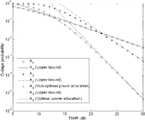
도 5는 본 발명의 일 실시예에 따른 분산 무선 통신 시스템에서 OSTBC 겸 빔 형성을 위한 적응식 전송 파워 할당 방식의 성능 특성 그래프5 is a performance characteristic graph of the adaptive transmission power allocation scheme for OSTBC and beamforming in a distributed wireless communication system according to an embodiment of the present invention
본 발명은 공간-시간 코딩 기술(space-time coding techniques)을 사용하는 분산형 입력 - 분산형 출력(distributed input - distributed output) 무선 통신 시스템에 관한 것으로, 특히 직교 공간 시간 블록 코드 겸 빔 형성을 위한 적응식 전송 파워 할당 방법에 관한 것이다.FIELD OF THE INVENTION The present invention relates to a distributed input-distributed output wireless communication system using space-time coding techniques, in particular for orthogonal space time block code and beam formation. The present invention relates to an adaptive transmission power allocation method.
무선 기술에서 상대적으로 새롭게 개발된 기술은 공간 멀티플렉싱 기술(spatial multiplexing) 및 공간-시간 코딩 기술이다. 공간-시간 코딩 중 특정 타입은 다중 입력 다중 출력(multiple input multiple output)을 위한 MIMO로서 지칭되며, 신호를 수신 및 송신하는데 있어서 다수의 안테나를 사용함으로써, 다수의 독립적 무선파가 동일한 주파수 범위 내에서 동일한 시간에 송신되도록 한다.Relatively new technologies in wireless technology are spatial multiplexing and space-time coding. A particular type of space-time coding is referred to as MIMO for multiple input multiple output, and by using multiple antennas to receive and transmit signals, multiple independent radio waves are identical within the same frequency range. To be transmitted in time.
근본적으로, MIMO 기술은 공통 주파수 대역 내에서 병렬적 공간 데이터 스트림을 생성함으로써 공간적으로 분산된 안테나의 사용을 기반으로 하고 있다. 개별적인 신호가 동일한 주파수 내에서 송신될지라도 수신기에서 분리되고 복조되어 다수의 통계적으로 독립된(즉, 효과적으로 분리된) 통신 채널들이 생성되도록 무선파들이 송신된다. 따라서, 다중 경로(즉, 시간상 지연되고 진폭 및 위상이 수성된 동일한 주파수의 다수의 신호들)를 금지하도록 하는 표준적인 무선 통신 시스템과는 대조적으로 MIMO는 적절한 주파수 대역 내에서 개선된 신호 대 잡음 비율 및 보다 높은 처리량을 성취하도록, 상관이 거의 없는(또는 약하게 상관된) 다중 경로 신호를 의존할 수 있다.In essence, MIMO technology is based on the use of spatially distributed antennas by generating parallel spatial data streams within a common frequency band. Although individual signals are transmitted within the same frequency, radio waves are transmitted so that they are separated and demodulated at the receiver to create a number of statistically independent (ie, effectively separated) communication channels. Thus, in contrast to a standard wireless communication system that allows for the prohibition of multipath (i.e., multiple signals of the same frequency delayed in time and amplitude and phase), MIMO provides improved signal-to-noise ratio within the appropriate frequency band And a multipath signal with little correlation (or weakly correlated) to achieve higher throughput.
MIMO 타입 기술의 한 특정한 응용 중에서, 하기 참조문헌[1], [2]에서 제공된 이론적 결과는 분산 안테나(DA: Distributed Antennas)가 위치 공유된(co-located) 다중 입력 다중 출력(C-MIMO) 채널에 비해 용량 측면에서 유리함을 입증하였다. 그러나, DA의 용량상의 이점을 충분히 얻기 위한 방법에 대해서는 아직 철저한 연구가 이루어지지 않은 상태이다. 이를 위해서 분산 무선 통신 시스템(DWCS: Distributed Wireless Communication System)의 개념이 하기 참조문헌[3]에 제안되었는데, 이 시스템은 송신 및 수신 신호를 함께 처리할 수 있어 시스템 용량을 크게 증가시킬 것으로 기대되고 있다.In one particular application of the MIMO type technology, the theoretical results provided in the following references [1], [2] show that multi-input multiple output (C-MIMO) with co-located distributed antennas (DA) It proved advantageous in terms of capacity over the channel. However, a thorough study has not yet been made on how to obtain the capacity advantage of DA. To this end, the concept of a Distributed Wireless Communication System (DWCS) has been proposed in Ref. [3], which is expected to greatly increase system capacity because it can process transmitted and received signals together. .
DWCS에서 하기 참조문헌[4]에 개시된 바와 같은 직교 공간 시간 블록 코드(OSTBC: Orthogonal Space Time Block Codes)와 빔 형성을 조합하면 매우 고무적인 결과를 낳는데, 왜냐하면 (DA로부터의) 거시적 다양성, (OSTBC로부터의) 송신/수신 밀도, 그리고 (빔 형성으로부터의) 어레이 이득을 이용하기 때문이다. 이 방안에 관한 이전의 연구에서는 주로 동일한 대규모(large-scale) 페이딩(섀도잉 및 경로 손실: shadowing and pathloss) 시나리오를 고려하였다. 그러나, 실제 시스템에서 일어나는 이동 단말(MT: Mobile Terminal)로부터 지리적으로 분산되어 있는 DA로의 대규모 페이딩은 크게 다를 수 있으며, 이는 전송 파워를 동일하게 할당하는 것이 비경제적임을 의미한다. 따라서, 채널 상태 정보(CSI: Channel State Information)에 기초한 전송 파워 할당이 필수적이다.The combination of Orthogonal Space Time Block Codes (OSTBC) and beam formation in DWCS as described in Ref. [4] has very encouraging results because of the macroscopic diversity (from DA), ( This is because it uses transmit / receive density (from OSTBC) and array gain (from beam formation). Previous work on this approach mainly considered the same large-scale fading (shadowing and pathloss) scenarios. However, large fading from a mobile terminal (MT) in a real system to a geographically dispersed DA may vary greatly, which means that it is uneconomical to allocate the same transmit power. Therefore, transmission power allocation based on channel state information (CSI) is essential.
도 1은 종래의 분산 무선 통신 시스템에서 직교 공간 시간 블록 코드(OSTBC: Orthogonal Space Time Block Codes)와 빔 형성을 조합한 전송 장치의 블록 구성도 이다. 도 1을 참조하면, 전송측에서 전송하고자 하는 데이터 심볼은 지정된 변조 방식에 의해 변조된 후 공간-시간 인코더(100)로 입력되어 공간-시간 부호화되며, 이후 부호화된 데이터 심볼들은 지리적으로 분산된 다수의 서브어레이(111)에 제공되어 각각 빔 형성된다. 도 1에 도시한 바와 같이, 종래에서는 다음과 같은 가정 하에 OSTBC 겸 빔 형성용 전송 방안을 채택한다.1 is a block diagram of a transmission apparatus combining orthogonal space time block codes (OSTBC) and beamforming in a conventional distributed wireless communication system. Referring to FIG. 1, a data symbol to be transmitted at a transmitting side is modulated by a designated modulation scheme, inputted to a space-
1) 지리적으로 분산되어 있는 빔 형성을 위한 일부 서브어레이(111) 중에 기지국 안테나가 분리되어 있다. MT(120)로부터 각 서브어레이(111)로의 대규모 페이딩은 동일하다고 가정한다.1) A base station antenna is separated among some
2) 각각의 서브어레이(111) 내의 안테나에 대해 반파장 간격을 이용한다. MT(110)로부터 각 서브어레이(111)까지 단일 경로가 존재하며, 주어진 서브어레이(111) 내에서 안테나에 의해 보여지는 채널은 어레이 응답 벡터에 의해 완벽히 상호 연관되어 있다. 이 어레이 응답 벡터는 피드백 또는 기타 도착 방향(DOA: Direction - of - Arrival) 추정 기법에 의해 추정할 수 있다.2) Half-wavelength spacing is used for the antennas in each
3) 상응하는 정규화 어레이 응답 벡터를 j번째 서브어레이(111)의 빔 형성 가중치 벡터로 직접 사용한다. 최대 개구 이득 qj을 얻도록 j번째 서브어레이(111)에 대해 완벽한 빔 형성을 가정한다(개구 이득은 한 안테나에 대해 안테나 어레이에 의해 달성되는 원하는 방향에서의 신호 파워의 평균의 증가로 볼 수 있으며, 이 때 양 시스템에서 전송되는 전체 파워는 동일하다고 가정한다).3) The corresponding normalized array response vector is used directly as the beamforming weight vector of the j th subarray 111. Assume perfect beamforming for the
4) 각각의 전송 서브어레이(111)로부터의 신호에서 독립적인 페이딩이 일어 날 수 있을 정도로 서브어레이(111)들이 충분히 멀리 떨어져 있다. 이 경우 각각의 서브어레이(101)를 등가 전송 유닛으로 볼 수 있다. 이 등가 유닛에 OSTBC를 인가하여 전송 다양성을 달성한다. 동일한 파워 할당을 채택한다.4) The
5) 준 정적 플랫 레일리(Rayleigh) 페이딩 채널을 가정한다.5) Assume a quasi-static flat Rayleigh fading channel.
6) 시스템은 완전히 동기화되어 있다.6) The system is fully synchronized.
7) 수신 안테나는 단 하나이다.7) There is only one receiving antenna.
그런데, 도 1에 도시한 바와 같은 종래의 OSTBC 겸 빔 형성용 전송 방안에서는 다음과 같은 문제점이 있었다.However, the conventional OSTBC and beamforming transmission scheme as shown in FIG. 1 has the following problems.
1) 레일리 페이딩은 비가시선(NLOS: None Line Of Sight) 통신 시나리오의 경우에만 적용된다. 그러나, DA의 분포로 인해 가시선(LOS: Line Of sight) 신호가 DWCS에 존재하는 경우가 종종 있다. 나카가미 페이딩(Nakagami fading)이 더 일반적인 페이딩 모델이며, 따라서 이를 대신 고려해야 한다.1) Rayleigh fading applies only to None Line Of Sight (NLOS) communication scenarios. However, due to the distribution of DA, line of sight (LOS) signals are often present in the DWCS. Nakagami fading is a more general fading model and should be considered instead.
2) MT로부터 지리적으로 분산되어 있는 DA로의 대규모 페이딩은 실제 시스템에서 크게 다를 수 있다. 따라서, 파워 할당을 동일하게 하면 허용 불가능한 수준의 성능이 초래될 수 있다. 전송 파워를 최적으로 할당해야 한다.2) Large scale fading from MT to geographically dispersed DA can be very different in a real system. Therefore, equal power allocation can result in unacceptable levels of performance. The transmission power should be optimally allocated.
3) 각각의 서브어레이에서의 안테나의 수는 모든 서브어레이에 대해 동일하다고 가정한다. 실제 시스템에서는 각각의 서브어레이에서의 안테나 수를 통신 환경에 따라 적응식으로 구성해야 한다.3) It is assumed that the number of antennas in each subarray is the same for all subarrays. In a real system, the number of antennas in each subarray must be adaptively configured according to the communication environment.
따라서, 본 발명의 목적은 최적에 근접한 성능을 발휘할 수 있는 DWCS에서의 OSTBC 겸 빔 형성을 위한 최적에 가까운 파워 할당 방안을 제공할 수 있는 방법을 제공함에 있다.Accordingly, an object of the present invention is to provide a method capable of providing a near optimal power allocation scheme for OSTBC and beam forming in DWCS that can exhibit near optimal performance.
본 발명의 다른 목적은 DWCS 내의 준-자율(quasi-static) 나카가미 페이딩 채널에서의 OSTBC 겸 빔 형성을 위한 적응식 전송 파워 할당 방안을 제공하여 주어진 목표 용량 및 전체 전송 파워에 대해 작동 중지 확률을 최소할 수 있는 방법을 제공함에 있다.Another object of the present invention is to provide an adaptive transmit power allocation scheme for OSTBC and beamforming in quasi-static Nakagami fading channels in DWCS to provide downtime probability for a given target capacity and total transmit power. To provide a way to minimize.
상기한 목적을 달성하기 위하여 본 발명의 일 양상은 분산 무선 통신 시스템에서의 직교 공간 시간 블록 코드 겸 빔 형성을 위한 적응식 전송 파워 할당 장치에 있어서, 각각 다수개의 분산 안테나가 무작위로 그룹을 이루며 위치해 있는, 다수개의 지리적으로 분산되어 있는 빔 형성을 위한 서브어레이와; 수신측으로부터 피드백된 상기 서브어레이 각각의 대규모 페이딩에 대한 정보를 이용하여, 상기 다수의 서브어레이에서 조합 가능한 서브세트별 미리 설정된 파워 할당 방식을 적용하여 성능을 확인하며, 상기 확인한 성능에 따라 최선의 성능을 가지는 서브세트를 최적의 서브세트로 설정하며, 이에 따른 파워 할당을 수행하는 중앙 처리 유닛을 구비함을 특징으로 한다.In order to achieve the above object, an aspect of the present invention is an adaptive transmission power allocation apparatus for orthogonal space time block code and beam forming in a distributed wireless communication system, each of which is located in a random group of distributed antennas A subarray for forming a plurality of geographically dispersed beams; Using the information on the large-scale fading of each of the subarrays fed back from the receiver, performance is confirmed by applying a preset power allocation scheme for each subset that can be combined in the plurality of subarrays, and the best performance is determined according to the checked performance. And a central processing unit for setting the subset having the performance to an optimal subset and thus performing power allocation.
본 발명의 다른 양상은 각각 다수개의 분산 안테나가 무작위로 그룹을 이루며 위치해 있는, 다수개의 지리적으로 분산되어 있는 빔 형성을 위한 서브어레이를 구비한 분산 무선 통신 시스템에서의 직교 공간 시간 블록 코드 겸 빔 형성을 위한 적응식 전송 파워 할당 방법에 있어서, 상기 각각의 서브어레이에 대해 DOA(Direction - of - Arrival)를 추정하고, 각각의 안테나 서브어레이에 대해 어레이 응답 벡터를 생성하는 과정과, 수신측으로부터 피드백된 상기 서브어레이 각각의 대규모 페이딩에 대한 정보를 이용하여, 상기 다수의 서브어레이에서 조합 가능한 서브세트별 상기 각각의 서브어레이의 나카가미 페이딩 파라미터 m에 비례하는 전송 파워를 할당하여, 상기 각각의 서브세트별 작동 중지 확률을 구하는 과정과, 상기 구한 작동 중지 확률이 가장 낮은 서브세트를 최적의 서브세트로 설정하며 이에 따른 파워 할당을 수행함을 특징으로 한다.Another aspect of the present invention is an orthogonal space time block code and beamforming in a distributed wireless communication system having a plurality of geographically dispersed beamforming subarrays, each of which is located in a random group of distributed antennas. In the adaptive transmission power allocation method for a method, the method comprising: estimating a direction-of-arrival (DOA) for each subarray, generating an array response vector for each antenna subarray, and feedback from a receiver By using the information on the large-scale fading of each of the sub-arrays, a transmission power proportional to the Nakagami fading parameter m of each sub-array per subset that can be combined in the plurality of sub-arrays is allocated, and the sub-arrays are allocated. The process of calculating the set down probability of each set, and the calculated down probability Sets the optimal subset to the sub-set and is characterized by carrying out the power allocation accordingly.
이하 본 발명에 따른 바람직한 실시예를 첨부한 도면을 참조하여 상세히 설명한다. 하기 설명에서는 구체적인 구성 소자 등과 같은 특정 사항들이 나타나고 있는데 이는 본 발명의 보다 전반적인 이해를 돕기 위해서 제공된 것일 뿐 이러한 특정 사항들이 본 발명의 범위 내에서 소정의 변형이나 혹은 변경이 이루어질 수 있음은 이 기술분야에서 통상의 지식을 가진 자에게는 자명하다 할 것이다.Hereinafter, exemplary embodiments of the present invention will be described in detail with reference to the accompanying drawings. In the following description, specific details such as specific components are shown, which are provided to help a more general understanding of the present invention, and it is understood that these specific details may be changed or changed within the scope of the present invention. It is self-evident to those of ordinary knowledge in Esau.
본 발명에서는 수신기로부터 송신기로 피드백되는 대규모 페이딩 정보(경로 손실 및 섀도잉)에 기초한, 분산 무선 통신 시스템의 플랫 나카가미 페이딩 채널 내에서의 OSTBC 겸 빔 형성 전송 방안을 위한 적응식의 작동 중지 확률에 기초한 전송 파워 할당 방안을 제안한다.The present invention relates to an adaptive downtime probability for the OSTBC and beamforming transmission scheme in the flat Nakagami fading channel of a distributed wireless communication system based on large scale fading information (path loss and shadowing) fed back from the receiver to the transmitter. A transmission power allocation scheme is proposed.
이때 송신기는 지리적으로 분산되어 있는 분포 안테나 서브어레이를 위하여 MT의 DOA를 추정하고, 각각의 서브어레이 내에서 빔 형성을 실행하여, 추정된 어레 이 응답 벡터를 이용하여 어레이 이득을 달성한다. OSTBC 심볼을 서브어레이로 전송하여 전송 다양성을 달성한다. 이때, 통신 환경을 고려하여 각각의 서브어레이에 대해 안테나 수를 유동적으로 한다. 고밀도 통신 지역의 경우에는 더 많은 안테나를 서브어레이에 배치할 수 있다. 또한 각각의 서브어레이에 대한 나카가미 페이딩 파라미터 m은 반드시 동일하지는 않다.In this case, the transmitter estimates the DOA of the MT for geographically dispersed distributed antenna subarrays, performs beamforming in each subarray, and achieves an array gain using the estimated array response vector. Transmit diversity is achieved by sending OSTBC symbols to subarrays. At this time, the number of antennas is made flexible for each subarray in consideration of the communication environment. In the case of high density communication areas, more antennas can be placed in the subarray. In addition, the Nakagami fading parameter m for each subarray is not necessarily the same.
전송 안테나 서브세트는 서브어레이의 임의의 조합이다. 본 발명의 파워 할당 방안은 파워 할당이 최적화된 최선의 서브세트를 선택한다. 또한 임의의 전송 안테나 서브세트를 위한 준 최적 파워 할당 방안은 각각의 서브어레이의 나카가미 페이딩 파라미터 m에 비례하는 전송 파워를 할당한다. 이 전송 할당은 충분히 높은 전송 파워 레벨에서 최적의 파워 할당에 매우 가깝다.The transmit antenna subset is any combination of subarrays. The power allocation scheme of the present invention selects the best subset in which power allocation is optimized. The quasi-optimal power allocation scheme for any subset of transmit antennas also allocates transmit power proportional to the Nakagami fading parameter m of each subarray. This transmission allocation is very close to the optimal power allocation at sufficiently high transmission power levels.
각각의 안테나 서브세트로의 준 최적 파워 할당에 기초하여 안테나 서브세트 선택을 행함으로써, 임의의 전송 파워 레벨에서 최적의 성능에 가까운, 전송을 위한 최선의 작동 중지 성능을 갖는 서브세트를 선택한다.By performing antenna subset selection based on the quasi-optimal power allocation to each antenna subset, the subset with the best downtime performance for transmission is selected that is close to optimal performance at any transmit power level.
이하 이러한 본 발명의 특징을 첨부 도면을 참조하여 보다 상세히 설명하기로 한다.Hereinafter, features of the present invention will be described in detail with reference to the accompanying drawings.
[시스템 모델][System model]
도 2는 본 발명의 일 실시예에 따른 분산 무선 통신 시스템에서 OSTBC와 빔 형성을 조합한 전송 장치의 블록 구성도로서, 다운링크 단일 사용자 (n, l, q1,…, qㅣ, 1) DWCS를 고려한다. 도 2에 도시된 바와 같이, 본 발명에서는 l개의 지리적으 로 분산되어 있는 빔 형성을 위한 서브어레이(211)에 각각 n개의 DA가 무작위로 그룹을 이루며 위치해 있으며, qj개의 DA가 j번째(j=1, 2,…,l) 서브어레이(211)에 있고,
각각의 서브어레이(211) 내의 안테나에 대해 반파장 간격을 이용한다. MT(220)로부터 각 서브어레이(211)까지 단일 경로가 존재하며, 주어진 서브어레이(211) 내에서 안테나에 의해 보여지는 채널은 어레이 응답 벡터에 의해 완벽히 상호 연관되어 있다고 가정한다. 이 어레이 응답 벡터는 DOA 추정 기법에 의해 추정할 수 있다. 상응하는 정규화 어레이 응답 벡터를 j번째 서브어레이(211)의 빔 형성 가중치 벡터로 직접 사용한다. 최대 개구 이득 qj을 얻도록 j번째 서브어레이(211)에 대해 완벽한 빔 형성을 가정한다. 이 경우 각각의 서브어레이(211)를 등가 전송 유닛으로 볼 수 있다. 이 등가 유닛에 OSTBC를 인가하여 전송 다양성을 달성한다.Half-wavelength spacing is used for the antennas in each
본 발명에서는 중앙 처리 유닛(200)에서 최적의 파워 할당을 가지는 최적의 전송 안테나 서브세트(안테나 서브어레이의 조합)를 먼저 얻는다. 그리고 나서, 공간-시간 인코더(201)에 의해 단위 평균 파워의 OSTBC 심볼을 생성하고, 전송 전에 파워 할당 행렬 P를 먼저 곱한다. 각각의 서브어레이(211) 내에서의 파워 할당은 동일하다고 가정한다. 따라서, 대각선(diagonal) 파워 할당 행렬 P는

도 3은 본 발명의 일 실시예에 따른 분산 무선 통신 시스템에서 OSTBC 전송 방식의 유효 입력 및 출력 관계를 나타낸 도면이다. 도 3에 도시된 바와 같이, 본 발명의 경우, 유효 입력 및 출력 관계는 하기 수학식 1과 같이 나타낼 수 있다.3 is a diagram showing the effective input and output relationship of the OSTBC transmission scheme in a distributed wireless communication system according to an embodiment of the present invention. As shown in FIG. 3, in the case of the present invention, an effective input and output relationship may be represented by

상기 수학식 1에서 y 와 x는 수신 및 송신 벡터이고, n은 독립적으로 식별되게 분산된(i.i.d) 복합


상기 수학식 2에서,


전송 안테나 서브세트를 DA 서브어레이의 임의의 조합으로 정의한다. 이때 서브어레이의 개수가 l이므로 총


[작동 중지 확률 유도][Derivation of downtime probability]
준 자율 플랫(flat) 나카가미 페이딩 채널에서의 OSTBC 겸 빔 형성 방안의 경우 작동 중지 확률(outage probability)은 효과적인 성능의 척도가 된다. 따라서, 본 발명에서는 작동 중지 확률을 최소화하여 전송을 최적화하기 위한 파워 할당 방안을 제안한다. 레이트가 rl인 서브세트 Al의 작동 중지 확률은 다음과 같이 유도된다.For OSTBC and beamforming schemes in quasi-autonomous flat Nakagami fading channels, the outage probability is an effective measure of performance. Accordingly, the present invention proposes a power allocation scheme for optimizing transmission by minimizing the probability of downtime. The probability of downtime for subset Al with rate rl is derived as follows.
채널 용량은


상기 수학식 3에서


상기 수학식 5에서서 계수

따라서,


최종적으로, 데이터 레이트가 R 인 작동 중지 확률

임의의 기타 서브세트에 걸쳐 전송되는 OSTBC의 경우에도 작동 중지 확률을 얻을 수 있다. 각각의 서브세트에 파워를 최적으로 할당하고, 전송을 위해 작동 중지 성능이 최선인 서브세트를 선택함으로써 각 서브세트의 작동 중지 확률을 최소화할 수 있다. 그런데, 이러한 작동 중지 확률을 직접 최소화하기가 어려우므로 다음과 같은 준 최적 방안을 따른다.The probability of downtime can also be obtained for OSTBC transmitted across any other subset. By optimally allocating power to each subset and selecting the subset with the best downtime performance for transmission, the probability of downtime for each subset can be minimized. However, since it is difficult to directly minimize the probability of such downtime, the following suboptimal scheme is followed.
[준 최적 파워 할당 방안을 이용한 안테나 서브세트 선택][Selection of antenna subset using quasi-optimal power allocation scheme]
상이한 TSNR 레벨에서 OSTBC의 최적의 전송을 위해 상이한 서브세트를 이용할 수 있다. TSNR 레벨


상기 수학식 9에서 부등식은 횔더(H㎝lder)의 적분 부등식을 적용한다.


준 최적 파워 할당 벡터


라그랑지(Lagrangian) 방법을 이용하면 하기 수학식 12와 같이

상기 파워 할당 방안은 고 TSNR 영역에서 정확한데, 왜냐하면


도 4는 본 발명의 일 실시예에 따른 분산 무선 통신 시스템에서 OSTBC 겸 빔 형성을 위한 적응식 전송 파워 할당 동작의 흐름도로서, 도 4에 도시된 파워 할당 방안의 흐름도에 도시된 바와 같이, 최적의 서브세트를 얻기 위해서는,4 is a flowchart of an adaptive transmission power allocation operation for forming OSTBC and beams in a distributed wireless communication system according to an embodiment of the present invention, as shown in the flowchart of the power allocation scheme shown in FIG. To get a subset,
- 먼저 초기화를 행한다. 즉, i=1, A=Ai, P=P0=1로 설정하는데, 여기서 A는 최적의 안테나 서브세트를 나타내고, P는 최적의 작동 중지 확률(본 발명에서는 준 최적의 작동 중지 확률)을 나타낸다(401단계).-Initialize first. That is, i = 1, A = Ai , P = P0 = 1, where A represents an optimal subset of antennas, and P represents an optimal probability of downtime (in this invention, a quasi-optimal downtime probability). (Step 401).
- 각각의 서브어레이에 대해 DOA를 추정하고, 각각의 안테나 서브어레이에 대해 어레이 응답 벡터를 생성한다. 이때 MT는 대규모 페이딩 정보를 송신기로 피드백하는 것으로 가정하며, 이를 제공받는다(402단계).Estimate the DOA for each subarray and generate an array response vector for each antenna subarray. In this case, it is assumed that the MT feeds back large fading information to the transmitter, and is provided (step 402).
- 서브세트 Ai에서의 각각의 서브어레이의 페이딩 파라미터 m에 비례하는 전송 파워를 할당하기 위한 준 최적 파워 할당 방안을 이용하여 서브세트 Ai에 대한 준 최적 작동 중지 확률 Pi을 계산한다(403단계).- by using a sub-optimal power allocation scheme for allocating the transmit power that is proportional to the fading parameter m of each sub-array in the subset Ai calculates a sub-optimal down probability Pi for a subset Ai (403 step).
- 이때 계산한 작동 중지 확률 Pi<=Pi-1인지 확인하여(404단계), Pi<=Pi-1이면 A=Ai, P=Pi로 설정한다(405단계). 이러한 과정에 따라 각 서브세트별 작동 중지 확률 중 가장 최적(가장 작은 값)의 작동 중지 확률이 확인되고 그에 대응되는 해당 서브세트를 확인할 수 있게 된다.At this time, it is determined whether the calculated operation probability Pi <= Pi-1 (step 404), and if Pi <= Pi-1 , sets A = Ai and P = Pi (step 405). According to this process, the most optimal (smallest value) of the downtime probability of each subset is checked, and the corresponding subset can be identified.
- 이후 i<2l-1인지 확인하여(406단계), i<2l-1일 경우에 i=i+1한 후에(407단계) 해당 서브세트에서 작동 중지 확률을 계산하는 동작을 반복적으로 수행하며, 그렇지 않으면 프로그램을 종료하고 A와 P를 출력한다.After that, check if i <2l -1 (step 406), i = i + 1 if i <2l -1 (step 407), and repeat the operation of calculating the probability of downtime in that subset. Otherwise, exit the program and print A and P.
[수치 결과}[Numeric results]
본 발명에 따른 방안의 성능을 검사하기 위하여, 예를 들어, 4개의 DA가 2개의 서브어레이로서 그룹을 이루고 있고 수신기가 1개의 안테나를 구비하며 정규화된 대규모 페이딩이

도 5는 준 최적 파워 할당(즉, 서브어레이1에는 1/3의 파워를 할당하고 서브어레이 2에는 2/3의 파워를 할당)의 경우의 A1, A2, A3의 작동 중지 확률과, 수치적 최적화를 통해 얻은 최적 파워 할당의 경우의 A3의 작동 중지 확률을 보여주고 있다. 준 최적 파워 할당의 경우의 A1, A2, A3의 작동 중지 확률의 상한도 도시하였다.5 shows the probability of downtime of A1 , A2 , and A3 for a quasi-optimal power allocation (i.e., one-third power is assigned to
도 5에 도시된 바와 같이, 고 TSNR 영역에서 상한이 조밀함을 관찰할 수 있다. 또한, 고 TSNR 레벨에서 A3의 준 최적 성능이 최적 성능에 매우 가깝다.As shown in FIG. 5, it can be observed that the upper limit is dense in the high TSNR region. In addition, the quasi-optimal performance of A3 at high TSNR levels is very close to the optimal performance.
TSNR이 12dB 미만이면 A1 상의 빔 형성이 최선이다. TSNR이 22.5dB를 초과하면 A2 상에서의 빔 형성 성능이 A1 상의 경우보다 좋다. TSNR이 12dB를 초과하면 A2 상에서의 OSTBC와 빔 형성의 조합이 최선이다. 안테나 선택에 따른 준 최적 성능은 임의의 TSNR 레벨에서 최적에 가깝다.If the TSNR is less than 12dB, beamforming on A1 is best. If the TSNR exceeds 22.5 dB, the beamforming performance on A2 is better than that on A1 . If the TSNR exceeds 12 dB, the combination of OSTBC and beamforming on A2 is best. The quasi-optimal performance of antenna selection is close to optimal at any TSNR level.
A2 상에서 순수 빔 형성과 비교할 때의 본 발명에 따른 파워 할당 방안의 성능상 이점은 분명하다. 즉, 10-2 및 10-3 작동 중지 레벨에서 TSNR이 각각 6dB 및 7dB 감소하였다.The performance advantage of the power allocation scheme according to the invention as compared to pure beam formation on A2 is evident. That is, at 10−2 and 10−3 shutdown levels, TSNRs decreased by 6 dB and 7 dB, respectively.
상기와 같이 본 발명의 일 실시예에 따른 DWCS의 OSTBC 겸 빔 형성을 위한 적응식 전송 파워 할당 동작이 이루어질 수 있으며, 한편 상기한 본 발명의 설명에서는 구체적인 실시예에 관해 설명하였으나 여러 가지 변형이 본 발명의 범위를 벗어나지 않고 실시될 수 있다. 따라서 본 발명의 범위는 설명된 실시예에 의하여 정할 것이 아니고 청구범위와 청구범위의 균등한 것에 의하여 정하여져야 할 것이다.As described above, the adaptive transmission power allocation operation for forming the OSTBC and beam of the DWCS according to the embodiment of the present invention can be made. Meanwhile, the above-described description of the present invention has been described with reference to specific embodiments, but various modifications have been made. It may be practiced without departing from the scope of the invention. Therefore, the scope of the present invention should not be defined by the described embodiments, but by the claims and equivalents of the claims.
상기한 바와 같이, 본 발명은 송신기에서 대규모 페이딩이 일어난다는 가정 하에 작동 중지 확률을 최소화하기 위하여 DWCS 내의 플랫 나카가미 페이딩 채널에서의 OSTBC 겸 빔 형성을 위한 적응식 준 최적 파워 할당 방안을 제안한다. 대규모 페이딩 정보가 변하면 파워 할당도 이에 따라 변할 수 있다.As described above, the present invention proposes an adaptive quasi-optimal power allocation scheme for OSTBC-cum beam formation in the flat Nakagami fading channel in DWCS in order to minimize downtime probability assuming large fading occurs at the transmitter. As the large fading information changes, the power allocation can change accordingly.
대규모 페이딩은 큰 시간 규모로 변하기 때문에 본 발명에서의 피드백 오버로는 매우 제한된다. 또한, 매우 간단하지만 효과적인 준 최적 파워 할당 방안이 제안되는데, 이 방안에 따르면 각각의 서브어레이의 페이딩 파라미터에 비례하는 전송 파워를 할당한다. 이 파워 할당 방안은 고 전송 파워 영역에서 정확하다.Because large fading changes on a large time scale, feedback over in the present invention is very limited. In addition, a very simple but effective quasi-optimal power allocation scheme is proposed, which allocates a transmission power proportional to the fading parameter of each subarray. This power allocation scheme is accurate in the high transmit power range.
안테나 선택에 있어서 본 발명에 따른 성능은 임의의 전송 파워 레벨에서 준 정적 페이딩 환경에서의 최적의 성능과 매우 가까운 것으로 판명되었다. 서브어레이 중 하나에서의 순수한 빔 형성 방안과 비교할 때, 본 발명에 따르면 큰 성능 이득을 얻을 수 있다.The performance according to the invention in antenna selection has been found to be very close to the optimal performance in a quasi-static fading environment at any transmit power level. Compared with the pure beamforming scheme in one of the subarrays, a large performance gain can be obtained according to the present invention.
이와 같이 적응식으로 전송 파워 할당이 이루어지는 본 발명의 OSTBC 겸 빔 형성 방안은 거시 다양성 이득, 최대 다양성 이득 및 어레이 이득을 얻을 수 있다. 본 발명에 따른 방안은 3G 또는 4G 무선 통신 시스템에 폭넓게 응용할 수 있을 것으로 예상된다.As described above, the OSTBC-beam forming scheme of the present invention, in which transmission power allocation is adaptively obtained, can obtain macro diversity gain, maximum diversity gain, and array gain. The solution according to the invention is expected to be widely applicable to 3G or 4G wireless communication systems.
[참조 문헌]REFERENCES
[1]W. Roh and A. Paulraj, "MIMO channel capacity for the distributed antenna systems," in Proc. IEEE VTC'02, vol. 2, pp. 706709, 2002.[1] W. Roh and A. Paulraj, "MIMO channel capacity for the distributed antenna systems," in Proc. IEEE VTC'02, vol. 2, pp. 706709, 2002.
[2]H. Zhuang, L. Dai, L. Xiao and Y. Yao, "Spectral efficiency of distributed antenna system with random antenna layout," Electronics Letters,vol. 39, no. 6, pp. 495-496, 2003.[2] H. Zhuang, L. Dai, L. Xiao and Y. Yao, "Spectral efficiency of distributed antenna system with random antenna layout," Electronics Letters, vol. 39, no. 6, pp. 495-496, 2003.
[3]S. Zhou, M. Zhao, X. Xu, J. Wang, and Y. Yao, "Distributed wireless communication system: A new architecture for future public wireless access," IEEE Commun. Mag., vol. 41, no. 3, pp 108-113, 2003.[3] S. Zhou, M. Zhao, X. Xu, J. Wang, and Y. Yao, "Distributed wireless communication system: A new architecture for future public wireless access," IEEE Commun. Mag., Vol. 41, no. 3, pp 108-113, 2003.
[4]V. Tarokh, H. Jafarkhani, and A. R. Calderbank, "Space-time block codes from orthogonal designs," IEEE Trans. Inform. Theory, vol. 45, pp. 14561467, July 1999.[4] V. Tarokh, H. Jafarkhani, and A. R. Calderbank, "Space-time block codes from orthogonal designs," IEEE Trans. Inform. Theory, vol. 45, pp. 14561467, July 1999.
[5]P. Li, L. R. Zhang and H. C. So, "On a CombinedBeamforming/Space-Time Coding," IEEE Comm. Lett., vol. 8, no. 1, pp. 15-17, Jan. 2004.[5] P. Li, L. R. Zhang and H. C. So, "On a Combined Beamforming / Space-Time Coding," IEEE Comm. Lett., Vol. 8, no. 1, pp. 15-17, Jan. 2004.
[6]R. W. Heath Jr. and A. Paulraj, "Multiple antenna arrays for transmitterdiversity and space-time coding," in Proc. IEEE Int.Conf. on Communications (ICC'99), vol. 1, June 1999, pp. 3640.[6] R. W. Heath Jr. and A. Paulraj, "Multiple antenna arrays for transmitter diversity and space-time coding," in Proc. IEEE Int. Conf. on Communications (ICC'99), vol. 1, June 1999, pp. 3640.
Claims (4)
Translated fromKoreanPriority Applications (2)
| Application Number | Priority Date | Filing Date | Title |
|---|---|---|---|
| KR1020060104046AKR100834631B1 (en) | 2006-10-25 | 2006-10-25 | Adaptive Transmit Power Allocation Method for Orthogonal Space-Time Block Code Cumbeam Formation in Distributed Wireless Communication Systems |
| US11/977,612US7949360B2 (en) | 2006-10-25 | 2007-10-25 | Method and apparatus for adaptively allocating transmission power for beam-forming combined with OSTBCs in a distributed wireless communication system |
Applications Claiming Priority (1)
| Application Number | Priority Date | Filing Date | Title |
|---|---|---|---|
| KR1020060104046AKR100834631B1 (en) | 2006-10-25 | 2006-10-25 | Adaptive Transmit Power Allocation Method for Orthogonal Space-Time Block Code Cumbeam Formation in Distributed Wireless Communication Systems |
Publications (2)
| Publication Number | Publication Date |
|---|---|
| KR20080037241A KR20080037241A (en) | 2008-04-30 |
| KR100834631B1true KR100834631B1 (en) | 2008-06-02 |
Family
ID=39330902
Family Applications (1)
| Application Number | Title | Priority Date | Filing Date |
|---|---|---|---|
| KR1020060104046AExpired - Fee RelatedKR100834631B1 (en) | 2006-10-25 | 2006-10-25 | Adaptive Transmit Power Allocation Method for Orthogonal Space-Time Block Code Cumbeam Formation in Distributed Wireless Communication Systems |
Country Status (2)
| Country | Link |
|---|---|
| US (1) | US7949360B2 (en) |
| KR (1) | KR100834631B1 (en) |
Families Citing this family (48)
| Publication number | Priority date | Publication date | Assignee | Title |
|---|---|---|---|---|
| US10187133B2 (en)* | 2004-04-02 | 2019-01-22 | Rearden, Llc | System and method for power control and antenna grouping in a distributed-input-distributed-output (DIDO) network |
| US11309943B2 (en) | 2004-04-02 | 2022-04-19 | Rearden, Llc | System and methods for planned evolution and obsolescence of multiuser spectrum |
| US8571086B2 (en)* | 2004-04-02 | 2013-10-29 | Rearden, Llc | System and method for DIDO precoding interpolation in multicarrier systems |
| US11451275B2 (en) | 2004-04-02 | 2022-09-20 | Rearden, Llc | System and method for distributed antenna wireless communications |
| US11394436B2 (en) | 2004-04-02 | 2022-07-19 | Rearden, Llc | System and method for distributed antenna wireless communications |
| US8654815B1 (en) | 2004-04-02 | 2014-02-18 | Rearden, Llc | System and method for distributed antenna wireless communications |
| US10985811B2 (en) | 2004-04-02 | 2021-04-20 | Rearden, Llc | System and method for distributed antenna wireless communications |
| US10200094B2 (en) | 2004-04-02 | 2019-02-05 | Rearden, Llc | Interference management, handoff, power control and link adaptation in distributed-input distributed-output (DIDO) communication systems |
| US10886979B2 (en) | 2004-04-02 | 2021-01-05 | Rearden, Llc | System and method for link adaptation in DIDO multicarrier systems |
| US10425134B2 (en) | 2004-04-02 | 2019-09-24 | Rearden, Llc | System and methods for planned evolution and obsolescence of multiuser spectrum |
| US10277290B2 (en) | 2004-04-02 | 2019-04-30 | Rearden, Llc | Systems and methods to exploit areas of coherence in wireless systems |
| US9826537B2 (en)* | 2004-04-02 | 2017-11-21 | Rearden, Llc | System and method for managing inter-cluster handoff of clients which traverse multiple DIDO clusters |
| US9819403B2 (en)* | 2004-04-02 | 2017-11-14 | Rearden, Llc | System and method for managing handoff of a client between different distributed-input-distributed-output (DIDO) networks based on detected velocity of the client |
| US8542763B2 (en) | 2004-04-02 | 2013-09-24 | Rearden, Llc | Systems and methods to coordinate transmissions in distributed wireless systems via user clustering |
| US9312929B2 (en) | 2004-04-02 | 2016-04-12 | Rearden, Llc | System and methods to compensate for Doppler effects in multi-user (MU) multiple antenna systems (MAS) |
| US8170081B2 (en) | 2004-04-02 | 2012-05-01 | Rearden, LLC. | System and method for adjusting DIDO interference cancellation based on signal strength measurements |
| US7633994B2 (en)* | 2004-07-30 | 2009-12-15 | Rearden, LLC. | System and method for distributed input-distributed output wireless communications |
| US10749582B2 (en) | 2004-04-02 | 2020-08-18 | Rearden, Llc | Systems and methods to coordinate transmissions in distributed wireless systems via user clustering |
| US9685997B2 (en) | 2007-08-20 | 2017-06-20 | Rearden, Llc | Systems and methods to enhance spatial diversity in distributed-input distributed-output wireless systems |
| KR101023366B1 (en)* | 2004-10-27 | 2011-03-18 | 삼성전자주식회사 | Apparatus and method for transmitting / receiving signals in a multiple input multiple output wireless communication system using a beamforming method |
| US8989155B2 (en) | 2007-08-20 | 2015-03-24 | Rearden, Llc | Systems and methods for wireless backhaul in distributed-input distributed-output wireless systems |
| KR101424280B1 (en)* | 2008-01-23 | 2014-07-31 | 엘지전자 주식회사 | In a multiple input / output system, a method of transmitting a signal |
| US8428653B2 (en)* | 2008-03-31 | 2013-04-23 | Mitsubishi Electric Research Laboratories, Inc. | Hot-spot wireless access exploiting shadowing diversity of distributed antennas |
| KR101408938B1 (en)* | 2008-04-02 | 2014-06-17 | 보드 오브 리전츠, 더 유니버시티 오브 텍사스 시스템 | Beamforming apparatus and method using generalized eigen analysis in MIMO wireless communication system |
| US8125917B2 (en)* | 2008-10-10 | 2012-02-28 | Avaya Inc. | Optimisation of transmission parameters of access points in wireless networks |
| CN101807976B (en)* | 2009-02-16 | 2015-09-16 | 中兴通讯股份有限公司 | A kind of Wave frequency processing device and method |
| WO2011031200A1 (en)* | 2009-09-14 | 2011-03-17 | Telefonaktiebolaget L M Ericsson (Publ) | Using a subframe time offset when scheduling downlink data transmissions |
| KR101155505B1 (en)* | 2010-11-03 | 2012-06-15 | 한국과학기술원 | System and mothod for mobile communication based on organic topology |
| KR101726593B1 (en)* | 2010-12-07 | 2017-04-13 | 삼성전자주식회사 | Method and appratus for limited feedback of channel state information in distributed antenna systems based wireless communication |
| US9030161B2 (en)* | 2011-06-27 | 2015-05-12 | Board Of Regents, The University Of Texas System | Wireless power transmission |
| US9282568B2 (en)* | 2011-11-18 | 2016-03-08 | Futurewei Technologies, Inc. | Method and system for dynamic, joint assignment of power and scheduling of users for wireless systems |
| US9648502B2 (en)* | 2012-08-15 | 2017-05-09 | Trimble Navigation Limited | System for tailoring wireless coverage to a geographic area |
| EP2898732B1 (en)* | 2012-09-24 | 2017-05-03 | Nec Corporation | Method and system for operating stations in a cooperative station network |
| US10194346B2 (en) | 2012-11-26 | 2019-01-29 | Rearden, Llc | Systems and methods for exploiting inter-cell multiplexing gain in wireless cellular systems via distributed input distributed output technology |
| US11050468B2 (en) | 2014-04-16 | 2021-06-29 | Rearden, Llc | Systems and methods for mitigating interference within actively used spectrum |
| US11189917B2 (en) | 2014-04-16 | 2021-11-30 | Rearden, Llc | Systems and methods for distributing radioheads |
| US11190947B2 (en) | 2014-04-16 | 2021-11-30 | Rearden, Llc | Systems and methods for concurrent spectrum usage within actively used spectrum |
| US10488535B2 (en) | 2013-03-12 | 2019-11-26 | Rearden, Llc | Apparatus and method for capturing still images and video using diffraction coded imaging techniques |
| US10164698B2 (en) | 2013-03-12 | 2018-12-25 | Rearden, Llc | Systems and methods for exploiting inter-cell multiplexing gain in wireless cellular systems via distributed input distributed output technology |
| US9923657B2 (en) | 2013-03-12 | 2018-03-20 | Rearden, Llc | Systems and methods for exploiting inter-cell multiplexing gain in wireless cellular systems via distributed input distributed output technology |
| US9973246B2 (en) | 2013-03-12 | 2018-05-15 | Rearden, Llc | Systems and methods for exploiting inter-cell multiplexing gain in wireless cellular systems via distributed input distributed output technology |
| RU2767777C2 (en) | 2013-03-15 | 2022-03-21 | Риарден, Ллк | Systems and methods of radio frequency calibration using the principle of reciprocity of channels in wireless communication with distributed input - distributed output |
| US9516607B2 (en)* | 2013-11-07 | 2016-12-06 | Lg Electronics Inc. | Method for determining transmission power |
| KR102230659B1 (en)* | 2013-11-11 | 2021-03-23 | 한국전자통신연구원 | Distributed array massive mimo system and method for operating distributed array massive mimo system |
| US11290162B2 (en) | 2014-04-16 | 2022-03-29 | Rearden, Llc | Systems and methods for mitigating interference within actively used spectrum |
| CN107113124B (en)* | 2014-08-28 | 2020-07-24 | 东南大学 | Omnidirectional transmission method and device for large-scale MIMO system |
| WO2018109603A1 (en)* | 2016-12-13 | 2018-06-21 | Amimon Ltd. | Analog signal transmission with multiple antennas |
| CN113205140B (en)* | 2021-05-06 | 2022-11-15 | 中国人民解放军海军航空大学 | Semi-supervised individual identification method of specific radiation source based on generative adversarial network |
Citations (4)
| Publication number | Priority date | Publication date | Assignee | Title |
|---|---|---|---|---|
| KR20010087715A (en) | 2000-03-08 | 2001-09-21 | 윤종용 | Method and apparatus for semi-blind transmit antenna array using feedback information in mobile communication system |
| KR20020041217A (en) | 2000-11-27 | 2002-06-01 | 윤종용 | Method and apparatus for semi-blind transmit antenna array employing chip level forward link channel estimation |
| KR20040004709A (en) | 2001-06-12 | 2004-01-13 | 탠티비 커뮤니케이션즈, 인코포레이티드 | Method and apparatus for frequency selective beam forming |
| KR20060063478A (en) | 2004-12-07 | 2006-06-12 | 에스케이 텔레콤주식회사 | Optimal Power Allocation Method for Multi-Input Mobile Communication System Using Generalized Orthogonal Space-Time Block Code Scheme |
Family Cites Families (8)
| Publication number | Priority date | Publication date | Assignee | Title |
|---|---|---|---|---|
| US6662024B2 (en)* | 2001-05-16 | 2003-12-09 | Qualcomm Incorporated | Method and apparatus for allocating downlink resources in a multiple-input multiple-output (MIMO) communication system |
| US6850741B2 (en)* | 2002-04-04 | 2005-02-01 | Agency For Science, Technology And Research | Method for selecting switched orthogonal beams for downlink diversity transmission |
| US8320301B2 (en)* | 2002-10-25 | 2012-11-27 | Qualcomm Incorporated | MIMO WLAN system |
| US7408975B2 (en)* | 2004-03-10 | 2008-08-05 | New Jersey Institute Of Technology | Transmit power adaptation for CDMA communication systems using successive interference cancellation |
| US7205937B2 (en)* | 2004-04-29 | 2007-04-17 | L-3 Integrated Systems Company | Non-multiple delay element values for phase shifting |
| KR101023366B1 (en)* | 2004-10-27 | 2011-03-18 | 삼성전자주식회사 | Apparatus and method for transmitting / receiving signals in a multiple input multiple output wireless communication system using a beamforming method |
| US7545323B2 (en)* | 2005-10-31 | 2009-06-09 | The Boeing Company | Phased array antenna systems and methods |
| KR100842619B1 (en)* | 2006-11-22 | 2008-06-30 | 삼성전자주식회사 | Adaptive Transmission Power Allocation Method for Orthogonal Space-Time Block Code and Beamforming Based on Symbol Error Rate in Distributed Wireless Communication Systems |
- 2006
- 2006-10-25KRKR1020060104046Apatent/KR100834631B1/ennot_activeExpired - Fee Related
- 2007
- 2007-10-25USUS11/977,612patent/US7949360B2/enactiveActive
Patent Citations (4)
| Publication number | Priority date | Publication date | Assignee | Title |
|---|---|---|---|---|
| KR20010087715A (en) | 2000-03-08 | 2001-09-21 | 윤종용 | Method and apparatus for semi-blind transmit antenna array using feedback information in mobile communication system |
| KR20020041217A (en) | 2000-11-27 | 2002-06-01 | 윤종용 | Method and apparatus for semi-blind transmit antenna array employing chip level forward link channel estimation |
| KR20040004709A (en) | 2001-06-12 | 2004-01-13 | 탠티비 커뮤니케이션즈, 인코포레이티드 | Method and apparatus for frequency selective beam forming |
| KR20060063478A (en) | 2004-12-07 | 2006-06-12 | 에스케이 텔레콤주식회사 | Optimal Power Allocation Method for Multi-Input Mobile Communication System Using Generalized Orthogonal Space-Time Block Code Scheme |
Also Published As
| Publication number | Publication date |
|---|---|
| US20080102881A1 (en) | 2008-05-01 |
| US7949360B2 (en) | 2011-05-24 |
| KR20080037241A (en) | 2008-04-30 |
Similar Documents
| Publication | Publication Date | Title |
|---|---|---|
| KR100834631B1 (en) | Adaptive Transmit Power Allocation Method for Orthogonal Space-Time Block Code Cumbeam Formation in Distributed Wireless Communication Systems | |
| KR100842619B1 (en) | Adaptive Transmission Power Allocation Method for Orthogonal Space-Time Block Code and Beamforming Based on Symbol Error Rate in Distributed Wireless Communication Systems | |
| KR100866188B1 (en) | Symbol Error Rate Approximation Method for Orthogonal Space Time Block Codes in Distributed Wireless Communication Systems | |
| US8145248B2 (en) | Apparatus and method for uplink beamforming and Space-Division Multiple Access (SDMA) in Multiple Input Multiple Output (MIMO) wireless communication systems | |
| JP5129346B2 (en) | Method for transmitting a precoded signal in a collaborative multiple-input multiple-output communication system | |
| JP4602641B2 (en) | Signal transmission system, signal transmission method and transmitter | |
| JP4173137B2 (en) | MIMO signal processing method with rank adaptive adaptation of data transmission rate | |
| KR101500026B1 (en) | Improved performance for a multiple antenna beamforming cellular network | |
| CN102857289B (en) | Signal generating apparatus for base station apparatus and termination | |
| KR101921669B1 (en) | Method and appratus for limited feedback of channel state information in massive mimo system based frequency division duplexing wireless communication | |
| JP4995319B2 (en) | Multi-user multiple-input multiple-output feedback and transfer in wireless communication systems | |
| US7933560B2 (en) | Apparatus and method for transmitting/receiving data in a mobile communication system using multiple antennas | |
| US20050213682A1 (en) | Apparatus and method for transmitting and receiving data in a mobile communication system using an array antenna | |
| KR100842620B1 (en) | Symbol Error Rate Based Transmission Power Allocation Method for Orthogonal Space Time Block Codes in Distributed Wireless Communication Systems | |
| KR20060037194A (en) | Apparatus and method for transmitting / receiving signals in a multiple input multiple output wireless communication system using a beamforming method | |
| JPWO2008004609A1 (en) | Wireless communication system and communication control method | |
| KR20050120520A (en) | System and method for allocating amc band in cellular ofdma systems with multiple antennas | |
| KR100809016B1 (en) | Method and Apparatus for Transmitting by Using Multiple Antenna Transmission Techniques Combined Beam Forming, MIMO and Diversity | |
| KR101399029B1 (en) | Apparatus and method for transmission of pilot in wireless communication system | |
| US20130016680A1 (en) | Systems and Methods for Multi-User MIMO | |
| KR20090043174A (en) | Transmission data generation method using precoding, transmission data generation method, generated transmission data reception method, and transmission device | |
| KR20090053599A (en) | Apparatus and method for data transmission / reception for transmission antenna selection and multiple input / output channel estimation for uplink data transmission in time division multiplexing wireless communication system including multiple input / output antennas | |
| JP2013509026A (en) | Adaptive beamforming and spatial frequency block coded transmission scheme for MIMO-OFDMA system |
Legal Events
| Date | Code | Title | Description |
|---|---|---|---|
| A201 | Request for examination | ||
| PA0109 | Patent application | St.27 status event code:A-0-1-A10-A12-nap-PA0109 | |
| PA0201 | Request for examination | St.27 status event code:A-1-2-D10-D11-exm-PA0201 | |
| D13-X000 | Search requested | St.27 status event code:A-1-2-D10-D13-srh-X000 | |
| D14-X000 | Search report completed | St.27 status event code:A-1-2-D10-D14-srh-X000 | |
| E902 | Notification of reason for refusal | ||
| PE0902 | Notice of grounds for rejection | St.27 status event code:A-1-2-D10-D21-exm-PE0902 | |
| P11-X000 | Amendment of application requested | St.27 status event code:A-2-2-P10-P11-nap-X000 | |
| P13-X000 | Application amended | St.27 status event code:A-2-2-P10-P13-nap-X000 | |
| E701 | Decision to grant or registration of patent right | ||
| PE0701 | Decision of registration | St.27 status event code:A-1-2-D10-D22-exm-PE0701 | |
| PG1501 | Laying open of application | St.27 status event code:A-1-1-Q10-Q12-nap-PG1501 | |
| GRNT | Written decision to grant | ||
| PR0701 | Registration of establishment | St.27 status event code:A-2-4-F10-F11-exm-PR0701 | |
| PR1002 | Payment of registration fee | St.27 status event code:A-2-2-U10-U11-oth-PR1002 Fee payment year number:1 | |
| PG1601 | Publication of registration | St.27 status event code:A-4-4-Q10-Q13-nap-PG1601 | |
| PR1001 | Payment of annual fee | St.27 status event code:A-4-4-U10-U11-oth-PR1001 Fee payment year number:4 | |
| PR1001 | Payment of annual fee | St.27 status event code:A-4-4-U10-U11-oth-PR1001 Fee payment year number:5 | |
| R18-X000 | Changes to party contact information recorded | St.27 status event code:A-5-5-R10-R18-oth-X000 | |
| FPAY | Annual fee payment | Payment date:20130429 Year of fee payment:6 | |
| PR1001 | Payment of annual fee | St.27 status event code:A-4-4-U10-U11-oth-PR1001 Fee payment year number:6 | |
| FPAY | Annual fee payment | Payment date:20140429 Year of fee payment:7 | |
| PR1001 | Payment of annual fee | St.27 status event code:A-4-4-U10-U11-oth-PR1001 Fee payment year number:7 | |
| FPAY | Annual fee payment | Payment date:20150429 Year of fee payment:8 | |
| PR1001 | Payment of annual fee | St.27 status event code:A-4-4-U10-U11-oth-PR1001 Fee payment year number:8 | |
| FPAY | Annual fee payment | Payment date:20160428 Year of fee payment:9 | |
| PR1001 | Payment of annual fee | St.27 status event code:A-4-4-U10-U11-oth-PR1001 Fee payment year number:9 | |
| FPAY | Annual fee payment | Payment date:20170427 Year of fee payment:10 | |
| PR1001 | Payment of annual fee | St.27 status event code:A-4-4-U10-U11-oth-PR1001 Fee payment year number:10 | |
| FPAY | Annual fee payment | Payment date:20180427 Year of fee payment:11 | |
| PR1001 | Payment of annual fee | St.27 status event code:A-4-4-U10-U11-oth-PR1001 Fee payment year number:11 | |
| LAPS | Lapse due to unpaid annual fee | ||
| PC1903 | Unpaid annual fee | St.27 status event code:A-4-4-U10-U13-oth-PC1903 Not in force date:20190528 Payment event data comment text:Termination Category : DEFAULT_OF_REGISTRATION_FEE | |
| PC1903 | Unpaid annual fee | St.27 status event code:N-4-6-H10-H13-oth-PC1903 Ip right cessation event data comment text:Termination Category : DEFAULT_OF_REGISTRATION_FEE Not in force date:20190528 |