KR100834626B1 - Sliding/swing type portable device with self-cradling - Google Patents
Sliding/swing type portable device with self-cradlingDownload PDFInfo
- Publication number
- KR100834626B1 KR100834626B1KR1020050028255AKR20050028255AKR100834626B1KR 100834626 B1KR100834626 B1KR 100834626B1KR 1020050028255 AKR1020050028255 AKR 1020050028255AKR 20050028255 AKR20050028255 AKR 20050028255AKR 100834626 B1KR100834626 B1KR 100834626B1
- Authority
- KR
- South Korea
- Prior art keywords
- main body
- battery pack
- sliding
- portable device
- battery
- Prior art date
- Legal status (The legal status is an assumption and is not a legal conclusion. Google has not performed a legal analysis and makes no representation as to the accuracy of the status listed.)
- Expired - Fee Related
Links
Images


Classifications
- H—ELECTRICITY
- H04—ELECTRIC COMMUNICATION TECHNIQUE
- H04B—TRANSMISSION
- H04B1/00—Details of transmission systems, not covered by a single one of groups H04B3/00 - H04B13/00; Details of transmission systems not characterised by the medium used for transmission
- H04B1/38—Transceivers, i.e. devices in which transmitter and receiver form a structural unit and in which at least one part is used for functions of transmitting and receiving
- H04B1/40—Circuits
- H—ELECTRICITY
- H04—ELECTRIC COMMUNICATION TECHNIQUE
- H04M—TELEPHONIC COMMUNICATION
- H04M1/00—Substation equipment, e.g. for use by subscribers
- H04M1/02—Constructional features of telephone sets
- H04M1/0202—Portable telephone sets, e.g. cordless phones, mobile phones or bar type handsets
- H04M1/0206—Portable telephones comprising a plurality of mechanically joined movable body parts, e.g. hinged housings
- H04M1/0208—Portable telephones comprising a plurality of mechanically joined movable body parts, e.g. hinged housings characterized by the relative motions of the body parts
- H04M1/0235—Slidable or telescopic telephones, i.e. with a relative translation movement of the body parts; Telephones using a combination of translation and other relative motions of the body parts
- G—PHYSICS
- G06—COMPUTING OR CALCULATING; COUNTING
- G06F—ELECTRIC DIGITAL DATA PROCESSING
- G06F1/00—Details not covered by groups G06F3/00 - G06F13/00 and G06F21/00
- G06F1/16—Constructional details or arrangements
- G06F1/1613—Constructional details or arrangements for portable computers
- G06F1/1615—Constructional details or arrangements for portable computers with several enclosures having relative motions, each enclosure supporting at least one I/O or computing function
- G06F1/1624—Constructional details or arrangements for portable computers with several enclosures having relative motions, each enclosure supporting at least one I/O or computing function with sliding enclosures, e.g. sliding keyboard or display
- H—ELECTRICITY
- H04—ELECTRIC COMMUNICATION TECHNIQUE
- H04M—TELEPHONIC COMMUNICATION
- H04M1/00—Substation equipment, e.g. for use by subscribers
- H04M1/02—Constructional features of telephone sets
- H04M1/0202—Portable telephone sets, e.g. cordless phones, mobile phones or bar type handsets
- H04M1/0206—Portable telephones comprising a plurality of mechanically joined movable body parts, e.g. hinged housings
- H04M1/0247—Portable telephones comprising a plurality of mechanically joined movable body parts, e.g. hinged housings comprising more than two body parts
- H—ELECTRICITY
- H04—ELECTRIC COMMUNICATION TECHNIQUE
- H04M—TELEPHONIC COMMUNICATION
- H04M1/00—Substation equipment, e.g. for use by subscribers
- H04M1/02—Constructional features of telephone sets
- H04M1/0202—Portable telephone sets, e.g. cordless phones, mobile phones or bar type handsets
- H04M1/0206—Portable telephones comprising a plurality of mechanically joined movable body parts, e.g. hinged housings
- H04M1/0208—Portable telephones comprising a plurality of mechanically joined movable body parts, e.g. hinged housings characterized by the relative motions of the body parts
- H04M1/0214—Foldable telephones, i.e. with body parts pivoting to an open position around an axis parallel to the plane they define in closed position
- H—ELECTRICITY
- H04—ELECTRIC COMMUNICATION TECHNIQUE
- H04M—TELEPHONIC COMMUNICATION
- H04M1/00—Substation equipment, e.g. for use by subscribers
- H04M1/02—Constructional features of telephone sets
- H04M1/0202—Portable telephone sets, e.g. cordless phones, mobile phones or bar type handsets
- H04M1/0206—Portable telephones comprising a plurality of mechanically joined movable body parts, e.g. hinged housings
- H04M1/0208—Portable telephones comprising a plurality of mechanically joined movable body parts, e.g. hinged housings characterized by the relative motions of the body parts
- H04M1/0225—Rotatable telephones, i.e. the body parts pivoting to an open position around an axis perpendicular to the plane they define in closed position
Landscapes
- Engineering & Computer Science (AREA)
- Signal Processing (AREA)
- Physics & Mathematics (AREA)
- Theoretical Computer Science (AREA)
- Mathematical Physics (AREA)
- Computer Hardware Design (AREA)
- Human Computer Interaction (AREA)
- General Engineering & Computer Science (AREA)
- General Physics & Mathematics (AREA)
- Computer Networks & Wireless Communication (AREA)
- Telephone Set Structure (AREA)
- Battery Mounting, Suspending (AREA)
Abstract
Translated fromKorean
Description
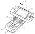
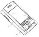
Translated fromKorean도 1은 본 발명의 바람직한 제1실시 예에 따른 슬라이딩/스윙 타입 휴대 장치를 나타내는 사시도.1 is a perspective view showing a sliding / swing type portable device according to a first embodiment of the present invention.
도 2는 본 발명의 바람직한 제1실시 예에 따른 슬라이딩/스윙 타입 휴대 장치가 완전히 슬라이딩된 상태를 나타내는 사시도.Figure 2 is a perspective view showing a state in which the sliding / swing-type portable device is completely sliding according to the first embodiment of the present invention.
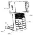
도 3은 본 발명의 바람직한 제1실시 예에 따른 슬라이딩/스윙 타입 휴대 장치가 완전히 스윙된 상태를 나타내는 사시도.Figure 3 is a perspective view showing a state in which the sliding / swing-type portable device completely swing according to the first embodiment of the present invention.
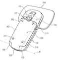
도 4는 도 3의 저면을 나타내는 사시도.4 is a perspective view illustrating the bottom of FIG. 3.
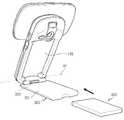
도 5는 본 발명의 바람직한 제1실시 예에 따른 슬라이딩/스윙 타입 휴대 장치가 거치된 상태를 나타내는 사시도.5 is a perspective view showing a state in which the sliding / swing-type portable device according to the first embodiment of the present invention is mounted.
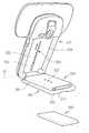
도 6은 본 발명의 바람직한 제1실시 예에 따른 슬라이딩/스윙 타입 휴대 장치의 배터리 셀이 분리된 상태를 나타내는 사시도.FIG. 6 is a perspective view illustrating a detached battery cell of a sliding / swinging type portable device according to a first embodiment of the present invention. FIG.
도 7은 본 발명의 바람직한 제1실시 예에 따른 슬라이딩/스윙 타입 휴대 장치의 본체 저면 하단을 나타내는 정면도.7 is a front view showing the bottom of the body bottom of the sliding / swing-type portable device according to a first embodiment of the present invention.
도 8은 본 발명의 바람직한 제1실시 예에 따른 배터리 커버에 제공되는 회전 각도에 따른 개폐힘을 나타내는 예시도.8 is an exemplary view showing the opening and closing force according to the rotation angle provided in the battery cover according to a first embodiment of the present invention.
도 9는 본 발명의 제2실시 예에 따른 자기 거치 기능을 구비한 슬라이딩/스잉 타입 휴대 장치를 나타내는 사시도.9 is a perspective view illustrating a sliding / singing type portable device having a magnetic mounting function according to a second embodiment of the present invention.
도 10는 본 발명의 제2실시 예에 따른 슬라이딩/스윙 타입 휴대 장치가 로드형 부재에 의해 안정적으로 거치된 상태를 나타내는 사시도.10 is a perspective view showing a state in which the sliding / swing-type portable device according to the second embodiment of the present invention is stably mounted by a rod-shaped member.
도 11은 본 발명의 제2실시 예에 따른 로드형 부재를 나타내는 정면도.11 is a front view showing a rod-shaped member according to a second embodiment of the present invention.
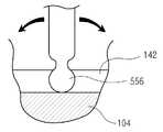
도 12a, 도 12b는 본 발명의 제2실시 예에 따른 로드형 부재가 결합된 상태를 일부 절개하여 각각 나타내는 종 단면도 및 횡 단면도.12A and 12B are longitudinal cross-sectional and lateral cross-sectional views each partially cut away showing a state in which a rod-like member is coupled according to a second embodiment of the present invention;
도 13은 본 발명의 제3실시 에에 따른 자기 거치 기능을 구비한 슬라이딩/스윙 타입 휴대 장치를 나타내는 사시도.Fig. 13 is a perspective view showing a sliding / swinging type portable device having a magnetic mounting function according to a third embodiment of the present invention.
도 14는 도 13의 저면쪽을 나타내는 사시도.FIG. 14 is a perspective view showing a bottom side of FIG. 13; FIG.
도 15는 본 발명의 제3실시 예에 따른 슬라이딩/스윙 타입 휴대 장치의 슬라이딩 하우징이 슬라이딩된 상태를 나타내는 사시도.FIG. 15 is a perspective view illustrating a sliding state of a sliding housing of a sliding / swing type portable device according to a third embodiment of the present invention; FIG.
도 16은 도 13에서 슬라이딩/스윙 하우징이 스윙되고, 배터리 팩이 회전되어서 자기 거치되 상태를 나타내는 사시도.FIG. 16 is a perspective view illustrating a sliding / swing housing swinging in FIG. 13 and a state in which the battery pack is rotated and magnetically mounted;
도 17은 도 16의 후방쪽을 나타내는 사시도.FIG. 17 is a perspective view of the rear side of FIG. 16; FIG.
본 발명은 셀룰러 폰(cellular phone), PDA(Personal Digital Assistants), HHP(Hand Held Phone), 게임 폰, 카메라 폰, 인터넷 폰, 디지털 통신 장치 등을 포함하는 휴대용 통신 장치에 관한 것으로서, 특히, 자체적으로 거치 기능을 구비함과 아울러 배터리 팩이 착탈식으로 제공되며, 사용자 정면으로 스테레오 사운드를 제공하고, 거치 동작이나 거치 상태 유지가 안정적인 슬라이딩/스윙 타입 휴대 장치에 관한 것이다.BACKGROUND OF THE
통상적인 개념의 "휴대용 통신 장치"라 함은 사용자가 휴대하면서 상대방과 무선 통신을 수행할 수 있는 전자 장치를 의미한다. 이러한 휴대용 통신 장치는 휴대성을 고려하여 소형화, 슬림화, 그립화 및 경량화되어가는 추세에 있으며, 보다 다양한 기능을 추구할 수 있는 멀티 미디어화 방향으로 나아가고 있는 추세에 있다. 특히, 점점 추후의 휴대용 단말기는 소형화, 경량화, 다기능, 다목적으로 사용될 것이며, 다양한 멀티 미디어 환경이나 인터넷 환경에 적응되도록 변형될 것이다. 아울러, 휴대용 단말기는 남녀노소, 전세계 어디에서도 통용되는 전자 장치로서, 항시 휴대하고 다녀야 할 필수품으로 인식되어 가고 있는 추세에 있다.The term “portable communication device” of a conventional concept refers to an electronic device that a user can carry out wireless communication with a counterpart while carrying. Such portable communication devices have been trending toward miniaturization, slimness, grip, and light weight in consideration of portability, and are moving toward a multi-mediaization direction to pursue more various functions. In particular, more and more portable terminals will be used for miniaturization, light weight, multifunction, and versatility, and will be modified to adapt to various multimedia environments or the Internet environment. In addition, the portable terminal is an electronic device commonly used anywhere in the world, men and women, and is being recognized as a necessity to carry around at all times.
보편화된 종래의 휴대용 통신 장치는 외관상으로 여러 타입으로 분류된다. 예를 들어, 휴대용 통신 장치는 외형에 따라서 바-형(bar-type), 플립-형(flip-type) 또는 폴더-형(folder-type) 통신 장치로 분류된다. 바-형 통신 장치는 단일 하우징이 바-형으로 구성된 것을 의미하고, 플립-형 통신 장치는 바-형의 하우징에 힌지장치에 의해 플립이 회전가능하게 구성된 것을 의미하며, 폴더-형 통신 장치는 단일의 바-형 하우징에 폴더가 힌지 장치에 의해 회전가능하게 연결되어 접는 방식 으로 구성된 것을 의미한다.Conventional portable communication devices are classified into various types in appearance. For example, portable communication devices are classified as bar-type, flip-type, or folder-type communication devices depending on their appearance. The bar-type communication device means that the single housing is configured as a bar-type, the flip-type communication device means that the flip is rotatably configured by the hinge device in the bar-type housing, the folder-type communication device is In a single bar-shaped housing, a folder is configured to be rotatably connected and folded by a hinge device.
또한, 휴대용 통신 장치는 신체 착용 위치 또는 착용 방식에 따라서 목걸이-형(neck wearable-type) 또는 손목착용-형(wrist-type)으로 분류되기도 한다. 목걸이-형 통신 장치는 끈을 이용하여 단말기를 목에 착용하는 휴대 방식을 의미하고, 손목착용-형 통신 장치는 손목에 단말기를 착용하는 휴대 방식을 의미한다.In addition, portable communication devices may be classified into either a neck wearable type or a wrist wear type according to a wearable position or a manner of wearing. A necklace-type communication device refers to a portable method of wearing a terminal around a neck using a string, and a wrist-wear type communication device refers to a portable method of wearing a terminal around a wrist.
또한, 휴대용 통신 장치는 개폐 방식에 따라서 회전-형(rotation-type) 또는 슬라이딩-형(sliding-type) 통신 장치로 분류되기도 한다. 회전-형 통신 장치는 두 개의 하우징이 마주보면서 대면한 상태를 계속 유지한 채 회전가능하게 연결되어 개폐되는 것을 의미하고, 슬라이딩-형 통신 장치는 두 개의 하우징이 길이방향으로 슬라이딩이동으로 개폐되는 것을 의미한다. 상기 열거된 다양하게 분류된 통신 장치는 당해 분야에서 통상의 지식을 가진자라면 용이하게 이해할 수 있을 것이다.In addition, the portable communication device may be classified into a rotation-type or sliding-type communication device according to an opening and closing method. The rotation-type communication device means that the two housings are rotatably connected and opened while remaining facing each other, and the sliding-type communication device means that the two housings are opened and closed by sliding movement in the longitudinal direction. it means. The variously classified communication devices listed above will be readily understood by those of ordinary skill in the art.
아울러, 종래의 휴대용 통신 장치는 음성 통신 기능 이외에 고속의 데이터를 통신할 수 있는 구조로 변환되고 가고 있다. 즉, 소비자의 욕구가 증대됨에 따라서 고속의 데이터를 전송하는 무선 통신 기술을 이용하여 서비스를 제공할 것이다.In addition, conventional portable communication apparatuses are being converted into structures capable of communicating high-speed data in addition to voice communication functions. That is, as the needs of consumers increase, the service will be provided using a wireless communication technology that transmits high speed data.
현재에는 종래의 휴대용 통신 장치에 카메라 렌즈가 채용되어져서 영상 신호 등의 전송이 이루어져 가고 있는 추세에 있다. 보편화된 휴대용 통신 장치는 카메라 렌즈 모듈을 외장형이나 내장형으로 구비하여 상대방과의 영상 통화나 원하는 피사체 촬영 기능을 수행할 수 있게 되었다.Currently, camera lenses have been adopted in conventional portable communication devices, and transmission of video signals and the like has been made. BACKGROUND OF THE INVENTION In general, portable communication devices have been equipped with a camera lens module as an external type or a built-in type to perform a video call with a counterpart or photograph a desired subject.
상기 열겨된 휴대 장치들은 사용자가 별도의 거치대를 구입하여 휴대 장치를 거치시키거나, 별도로 구입된 충전기를 이용하여 휴대 장치를 경사지게 거치하여 충전시키는 방식으로 사용되어져 왔다.The opened portable devices have been used in a manner in which a user purchases a separate holder to mount the portable device or charge the portable device by tilting the portable device using a separately purchased charger.
그러나, 사용자의 입장에서는 휴대 장치 거치를 위해서 별도의 거치대를 구비하는 것은 비 경제적이고, 별도도 제공된 충전기를 이용하여 충전하면서 거치하는 방식은 충전기를 필수적으로 휴대해야 하는 문제점이 발생한다. 예를 들어서, 충전기의 휴대가 불편하여서 충전기를 휴대하고 있지 않다면, 휴대 장치의 충전이 불가능하고, 거치도 불가능하다. 이를 위해서 충전기를 항시 휴대하고 다니는 것도 또한 불편한 문제점이 발생된다. 아울러, 휴대 장치의 거치 충전 시에도 제공된 표시 장치가 고정식으로 본체에 장착되는 구조이기 때문에 폰 모드 이외의 다양한 모드에는 표시 장치의 사용 극대화에 제약이 된다.However, from a user's point of view, it is inexpensive to provide a separate holder for mounting a portable device, and a method of mounting while charging using a separately provided charger causes a problem of carrying a charger essentially. For example, if the charger is inconvenient to carry, and the charger is not carried, the portable device cannot be charged or mounted. For this purpose, carrying a charger at all times also causes inconvenience. In addition, since the provided display device is fixedly mounted to the main body even when the portable device is mounted and charged, various modes other than the phone mode are limited in maximizing the use of the display device.
제약이 되는 이유는 휴대 장치의 게임 모드나 티브이 시청 모드 또는 비디오 시청 모드 시에는 표시 장치가 회전되어서 보다 넓게 디스플레이 화면이 제공되어져야 시청하기에 편리하기 때문이다. 또한, 음악 청취 모드에는 보다 넓은 표시 장치 제공과 함께 스테레오 사운드를 제공하는 환경이 제공되여저야 시청하기에 편리하기 때문이다. 따라서, 종래의 휴대 장치에 자체적 거치 기능, 보다 광폭의 표시 장치 제공, 스테레오 사운드 제공, 거치 시의 안정적인 거치 동작과 유지 등의 기능이 요구되었다.The reason for the limitation is that the display device is rotated in the game mode, the TV viewing mode, or the video viewing mode of the portable device so that it is convenient to view the display screen more widely. In addition, the music listening mode is provided with an environment for providing stereo sound with a wider display device, which is convenient for viewing at night. Accordingly, the conventional portable device has been required to have its own mounting function, to provide a wider display device, to provide stereo sound, and to perform stable holding operation and holding during mounting.
따라서, 본 발명의 목적은 자체적으로 거치 기능을 구비한 슬라이딩/스윙 타입 휴대 장치를 제공함에 있다.Accordingly, an object of the present invention is to provide a sliding / swing type portable device having a mounting function by itself.
본 발명의 다른 목적은 배터리 커버에 거치 기능이 제공된 슬라이딩/스윙 타입 휴대 장치를 제공함에 있다.Another object of the present invention to provide a sliding / swing type portable device provided with a mounting function on the battery cover.
본 발명의 다른 목적은 자체 거치 기능을 제공하도록 회전가능하게 연결된 배터리 커버에 배터리 팩이 착탈가능하게 일체형으로 제공되어서 배터리 팩의 자중에 의한 거치의 안정감을 제공할 수 있는 슬라이딩/스윙 타입 휴대 장치를 제공함에 있다.Another object of the present invention is to provide a sliding / swing-type portable device that can be provided to the battery cover rotatably connected to provide a self-mounting function detachably integrated to provide a stability of the mounting by the weight of the battery pack. In providing.
본 발명의 또 다른 목적은 화상 통화 모드나, 게임 모드나, 비디오 시청 모드, 티브이 시청 모드, 음악 청취 모드 시에 사용자에게 정면으로 향하는 스테레오 사운드를 제공함과 아울러 하우징의 스윙에 따른 슬라이딩/스윙 동작에 의해 표시 장치를 넓게 사용할 수 있는 슬라이딩/스윙 타입 휴대 장치를 제공함에 있다.It is still another object of the present invention to provide a stereo sound in front of the user in a video call mode, a game mode, a video watching mode, a TV watching mode, or a music listening mode, and to provide sliding / swing operation according to the swing of the housing. It is therefore an object of the present invention to provide a sliding / swing type portable device that can be widely used with a display device.
본 발명의 또 다른 목적은 배터리 팩을 이용한 거치 동작 시, 안정적이고 용이한 거치 동작과, 거치 후의 안정적인 거치 상태를 유지할 수 있는 슬라이딩/스윙 타입 휴대 장치를 제공함에 있다.Still another object of the present invention is to provide a sliding / swing type portable device capable of maintaining a stable and easy mounting operation and a stable mounting state after mounting during battery mounting operation.
상기한 목적들을 달성하기 위하여 본 발명은 휴대 장치에 있어서,In order to achieve the above object, the present invention provides a portable device,
본체;main body;
상기 본체 저면 소정위치에서 제1힌지축을 중심으로 회전가능하게 연결되어 가깝거나 멀어지고, 상기 본체 저면에서 제1각도 미만에서는 상기 본체쪽으로 닫힐려는 힘을 제공받고, 상기 제1각도 이상에서는 열릴려는 힘을 제공받으며, 제2각도에서는 정지하는 힘을 제공받아서 자체적으로 상기 본체를 경사지게 거치시킬 수 있는 배터리 커버; 및The main body bottom is rotatably connected to the first hinge axis at a predetermined position so as to be close to or far away from the main body is provided with a force to close to the main body less than the first angle, the force to open at the first angle or more Received, the second angle at the second angle is provided with a battery cover that can be mounted to the body inclined itself; And
상기 배터리 커버에서 착탈되는 배터리 팩으로 구성된다.It is composed of a battery pack detachable from the battery cover.
또한, 본 발명은 휴대 장치에 있어서,In addition, the present invention provides a portable device,
본체;main body;
상기 본체 상면과 대면한 상태를 계속적으로 유지한 채로 이동하는 슬라이딩/스윙 하우징;A sliding / swing housing which moves while continuously facing the upper surface of the main body;
상기 본체 상면에 장착되어 상기 슬라이딩/스윙 하우징의 슬라이딩 유무에 따라서 개폐되는 다수의 키들의 배열로 이루어진 제1키패드;A first keypad mounted on an upper surface of the main body and configured to have an arrangement of a plurality of keys opened and closed according to whether the sliding / swing housing slides;
상기 본체 상면에 장착되어 상기 슬라이딩/스윙 하우징의 스윙 유무에 따라서 개폐되는 한 쌍의 스테레오 스피커 장치;A pair of stereo speaker devices mounted on an upper surface of the main body and opened and closed according to the presence / absence of the sliding / swing housing;
상기 본체 상면에 장착되어서 상기 슬라이딩/스윙 하우징의 슬라이딩 및 스윙 이동 유무에 상관없이 항시 개방되는 마이크 장치;A microphone device mounted on an upper surface of the main body and always open regardless of sliding and swing movement of the sliding / swing housing;
상기 본체 저면 소정위치에서 제1힌지축을 중심으로 회전가능하게 연결되어서 상기 본체 저면에서 제1각도 미만에서는 상기 본체쪽으로 닫힐려는 힘을 제공받고, 상기 제1각도 이상에서는 열릴려는 힘을 제공받으며, 제2각도에서는 정지힘을 제공받아서 자체적으로 상기 본체를 경사지게 거치시키는 배터리 커버; 및The main body is rotatably connected about a first hinge axis at a predetermined position to receive a force to close toward the main body at less than a first angle on the bottom of the main body, and to open at a first angle or more. A battery cover which is inclinedly mounted on the main body by itself by receiving a stopping force at two angles; And
상기 배터리 커버에서 착탈되는 배터리 팩으로 구성된다.It is composed of a battery pack detachable from the battery cover.
또한, 본 발명은 휴대 장치에 있어서,In addition, the present invention provides a portable device,
본체;main body;
상기 본체 저면 하단에서 힌지축을 중심으로 회전가능하게 연결되어 가깝거나 멀어지는 배터리 커버;A battery cover which is rotatably connected to a hinge axis at a lower portion of the bottom of the main body to move closer or further away from each other;
상기 배터리 커버 내면에 일체형으로 박스형으로 제공되어 상기 본체 저면에 수용되는 배터리 하우징;A battery housing integrally provided on an inner surface of the battery cover and accommodated on a bottom surface of the main body;
상기 본체 저면에 길이 방향을 따라서 장착되어 상기 본체를 경사지게 지지하는 자기 거치 수단; 및Magnetic mounting means mounted on the bottom of the main body in a longitudinal direction to support the main body inclinedly; And
상기 배터리 하우징에서 착탈되는 배터리 팩으로 구성된다.It is composed of a battery pack detachable from the battery housing.
또한, 본 발명은 휴대 장치에 있어서,In addition, the present invention provides a portable device,
본체;main body;
상기 본체 상면과 대면한 상태를 계속적으로 유지한 채로 이동하는 슬라이딩/스윙 하우징;A sliding / swing housing which moves while continuously facing the upper surface of the main body;
상기 본체 상면에 장착되어 상기 슬라이딩/스윙 하우징의 스윙 유무에 따라서 개폐되는 스피커 장치;A speaker device mounted on an upper surface of the main body and opened / closed according to a swing of the sliding / swing housing;
상기 본체 저면 소정위치에서 제1힌지축을 중심으로 회전가능하게 연결되어서 제1각도 미만에서는 상기 본체쪽으로 닫힐려는 힘을 제공받고, 상기 제1각도 이상에서는 열릴려는 힘을 제공받으며, 제2각도에서는 정지힘을 제공받아서 자체적으로 상기 본체를 경사지게 거치시키는 배터리 팩; 및The main body is rotatably connected about a first hinge axis at a predetermined position to receive a force to close toward the main body below the first angle, a force to open above the first angle, and stop at a second angle. A battery pack configured to be inclined to mount the main body by itself by receiving a force; And
상기 배터리 팩과 상기 본체 저면 사이에 제공되어서 상기 배터리 팩의 안착 시에 안착 위치를 용이하게 잡아주는 제1홀딩 장치로 구성된다.And a first holding device provided between the battery pack and the bottom of the main body to easily hold a seating position when the battery pack is seated.
이하에서는 첨부도면을 참조하여 본 발명의 바람직한 일 실시 예를 상세히 설명하기로 한다. 본 발명을 설명함에 있어, 관련된 공지기능 혹은 구성에 대한 구체적인 설명은 본 발명의 요지를 모호하지 않게 하기 위하여 생략한다.Hereinafter, with reference to the accompanying drawings will be described in detail a preferred embodiment of the present invention. In describing the present invention, detailed descriptions of related well-known functions or configurations are omitted in order not to obscure the subject matter of the present invention.
도 1 내지 도 3에 도시된 바와 같이, 본 발명에 따른 휴대 장치는 본체(100)와, 상기 본체 저면(102:도 4에 도시됨)에 회전가능하게 연결되어서 자체적으로 상기 본체(100)를 경사지게 거치하는 배터리 커버(300:도 4에 도시됨)와, 상기 배터리 커버(300)에서 착탈되는 배터리 팩(도 4, 도 5에 도시됨)과, 상기 본체 상면(101)에서 평행하게 대면한 상태를 계속적으로 유지한 채로 슬라이딩함과 아울러 제2힌지축(A2:도 3에 도시됨)을 중심으로 스윙하는 슬라이딩/스윙 하우징(200)으로 구성된다.As shown in FIGS. 1 to 3, the portable device according to the present invention is rotatably connected to the
상기 배터리 커버(300) 및 상기 배터리 팩(400)은 후술하기로 한다.The
도 1에 도시된 바와 같이, 상기 본체(100)와 상기 슬라이딩/스윙 하우징(200)은 길이가 서로 상이하다. 상기 본체(100)의 길이가 상기 슬라이딩/스윙 하우징(200)의 길이보다 길게 구성된다. 따라서, 상기 본체 상면(101) 최하단 일측 모서리에는 상기 슬라이딩/스윙 하우징(200)에 의해 숨겨지지 않는 마이크 장치(110)가 배치되며, 상기 마이크 장치(110)는 상기 슬라이딩/스윙 하우징(200)의 슬라이딩 및 스윙 이동에 상관없이 항시 개방된다.As shown in FIG. 1, the
상기 슬라이딩/스윙 하우징(200)의 상면(201)에는 단일 키(210)와, 상기 단일 키(210)와 이웃하는 표시 장치(212)와, 상기 표시 장치(212)와 이웃하는 다수개의 키들의 배열로 이루어진 제2키패드(214)가 배치된다The
도 2는 상기 슬라이딩/스윙 하우징(200)이 상기 본체 상면(101)에서 길이방 향으로 완전히 슬라이딩된 상태를 나타내는 사시도이다. 도 2에 도시된 바와 같이, 상기 본체 상면(101)에는 다수 개의 키들의 배열로 이루어진 제1키패드(112)가 배치된다. 상기 제1키패드(112)는 3×4 배열로 배치되고, 상기 마이크 장치(110)와 이웃한다. 이 때, 상기 제1키패드(112)는 상기 슬라이딩/스윙 하우징(200)의 슬라이딩 유무에 따라서 개폐된다. 즉, 상기 슬라이딩/스윙 하우징(200)이 상기 본체 (100) 상에서 닫힌 상태에서는 숨겨지고, 상기 슬라이딩/스윙 하우징(200)이 상기 본체(100) 상에서 완전히 열린 상태에서는 상기 제1키패드(112)는 완전히 개방된다. 도 2와 같은 상태에는 상기 제1키패드(112)와 상기 제2키패드(214)가 서로 이웃함으로서, 상기 제1,2키패드(112,214)는 연속적으로 집합된다.2 is a perspective view illustrating a state in which the sliding /
도 3은 도 2에서 상기 슬라이딩/스윙 하우징(200)이 완전히 스윙된 상태를 나타내는 사시도이다. 도 3에 도시된 바와 같이, 상기 본체 상면(101) 소정위치에는 스테레오 사운드를 제공할 수 있는 한 쌍의 스테레오 스피커 장치(114,115)가 배치된다. 상기 한 쌍의 스테레오 스피커 장치(114,115)는 상기 슬라이딩/스윙 하우징(200)의 스윙 유무에 따라서 개폐된다. 상기 슬라이딩/스윙 하우징(200)이 상기 본체 상면(101)에서 스윙되지 않은 경우에는 상기 한 쌍의 스테레오 스피커 장치(114,115)는 숨겨지고(도 2에 도시됨), 상기 슬라이딩/스윙 하우징(200)이 상기 본체 상면(101)에서 완전히 스윙된 경우, 상기 한 쌍의 스테레오 스피커 장치(114,115)는 완전히 개방된다. 도 3과 같은 위치에서 상기 표시 장치(212)는 상기 한 쌍의 스테레오 스피커 장치(114,115)와 바로 이웃한다. 또한, 상기 한 쌍의 스테레오 스피커 장치(114,115)는 상기 본체 상면(101) 수직방향으로 향하게 스테레 오 사운드를 발산한다.3 is a perspective view illustrating a state in which the sliding /
도 4에 도시된 바와 같이, 상기 본체 저면(102)에는 배터리 팩(도 5에 도시됨)을 포함하는 배터리 커버(300)가 제1힌지축(A1)을 중심으로 회전가능하게 구성된다. 또한, 상기 저면(102)에는 카메라 렌즈(120)와, 상기 카메라 렌즈(120)와 이웃하게 조명 장치(122)가 배치된다. 상기 배터리 커버 외면(302)에는 적어도 하나 이상의 러버들(310,312,314,316)이 제공되고, 바람직하게 4개의 러버가 상기 외면 4군데 모서리 부근에 제공된다. 상기 본체 저면(102)에는 그의 하단을 따라서 상기 제1힌지축(A1)을 제공하는 힌지 장치가 배치된다. 상기 힌지 장치는 상기 본체(100)와 상기 배터리 커버(300)를 제1힌지축(A1)을 중심으로 회전가능하게 연결하는 기능을 담당하며, 상기 본체 저면(102) 하단 양 모서리에 형성된 한 쌍의 사이드 힌지 아암(130,132)과, 상기 배터리 커버(300) 하단에 형성되어 그의 양단이 상기 한 쌍의 사이드 힌지 아암(130,132)에 미도시된 힌지 모듈에 의해 각각 결합되는 센터 힌지 아암(320)으로 구성된다.As shown in FIG. 4, a
도 5, 도 6에 도시된 바와 같이, 상기 본체 저면(102)에는 상기 배터리 팩(400)을 포함하는 상기 배터리 커버(300)를 수용하기 위한 장방형의 슬롯(140)이 제공된다. 상기 배터리 팩(400)은 상기 배터리 커버 내면(301)에서 착탈된다. 물론, 상기 배터리 팩(400)은 다수 개의 배터리 셀로 구성된다. 상기 배터리 커버(300) 내면(301)에는 단차진 부위 측벽에 접속부(320)가 설치되고, 상기 배터리 팩(400)은 상기 접속부(320)에서 착탈된다. 바람직하게 상기 배터리 팩(400)은 상기 배터리 커버 내면(301)을 따라서 이동하여 착탈된다. 물론, 상기 배터리 팩(400)은 사용자의 강제적인 힘에 의해 장착 또는 분리된다. 상기 배터리 팩(400)의 장착 방식은 상기 배터리 커버의 내면(301)에 상기 배터리 팩을 놓고, 이어서 상기 내면(301)을 따라서 상기 접속부(320)로 상기 배터리 팩(400)을 강제적으로 밀면, 상기 접속부(320)에 상기 배터리 팩(400)의 미도시된 다른 접속부가 접속된다. 물론, 상기 접속부(320)가 메일형(male-type)으로, 상기 미도시된 배터리 팩(400)의 접속부가 피메일형(female-type)으로 구성될 수 있고, 상기 접속부(320)가 피메일형으로, 상기 미도시된 배터리 팩(400)의 접속부가 메일형으로 구성될 수 있다.As illustrated in FIGS. 5 and 6, the
상기 배터리 팩(400)이 상기 배터리 커버(300)에 접속된 상태로 장착되면, 상기 배터리 팩(400)은 상기 배터리 커버(300)와 함께 일체형으로 회전이동을 수행할 수 있으며, 상기 슬롯(140)에 안전하게 수용된다.When the
도 7에 도시된 바와 같이, 상기 힌지 모듈(142)은 상기 제1힌지축(A1)을 제공하는 기능을 담당하는 장치로서, 상기 힌지 모듈은 공지의 힌지 하우징과, 힌지 샤프트(143), 힌지 캠 및 힌지 스프링으로 구성된다. 상기 힌지 모듈(142)은 당해분야에서 통상의 지식을 가진자라면 용이하게 이해할 수 있을 것이다. 도 7에는 힌지 더미의 샤프트 부분(144)과, 힌지 모듈의 힌지 샤프트(143) 만이 도시되었다. 상기 힌지 모듈(140)은 제1각도 미만에서는 상기 배터리 커버(300)가 상기 본체 저면(102)쪽 방향, 즉, 닫힐려는 힘을 제공하고, 상기 제1각도 이상에서는 상기 본체 하우징 저면(102)에서 멀어지는 방향, 즉 열릴려는 힘을 제공하며, 제2각도에서는 상기 배터리 커버(300)의 거치 각도에서 정치하는 힘을 제공한다. 따라서, 상기 배터리 커버(300)는 상기 힌지 모듈(142)에 의해 힘을 제공받아서 상기 본체(100)를 경사지게 거치할 수 있는 기능을 담당한다.As shown in FIG. 7, the
상기 힌지 모듈은 상기 하나의 사이드 힌지 아암(132)에 장착된다. 아울러, 상기 힌지 모듈(142)과 대응되게 힌지 더미(144)가 다른 하나의 사이드 힌지 아암(130)에 장착된다. 상기 힌지 더미는 미도시된 연성 회로가 경유한다. 이 때, 상기 힌지 모듈(142)이나 상기 힌지 더미(144)는 상기 센터 힌지 아암에 장착될 수 있다.The hinge module is mounted to the one
도 2는 폰 모드로 사용되는 경우를 보여주고, 도 3은 게임 모드, 티브이 시청 모드, 주문형 비디오 모드, 음악 청취 모드로 사용되는 경우를 보여준다. 또한, 도 5는 휴대 장치가 상기 배터리 커버(300)를 이용하여 경사지게 거치된 상태를 보여준다.FIG. 2 shows a case where the phone mode is used, and FIG. 3 shows a case where the game mode, the TV viewing mode, the video on demand mode, and the music listening mode are used. 5 illustrates a state in which the portable device is inclinedly mounted using the
도 5에 도시된 바와 같이, 상기 배터리 팩이 상기 배터리 커버와 함께 할 수 있기 때문에, 도 5와 같은 상태에서 상기 배터리 팩의 자중에 의해 발생하는 거치의 안정감을 제공하게 된다.As shown in FIG. 5, since the battery pack may be combined with the battery cover, the battery pack may provide stability of mounting caused by the weight of the battery pack in the state as shown in FIG. 5.
도 3, 도 4에 도시된 바와 같이, 상기 제1힌지축(A1)은 상기 제2힌지축(A2)과 이격되며, 수직 방향으로 향한다. 또한, 상기 슬라이딩/스윙 하우징(200)의 슬라이딩 방향과 상기 제1힌지축(A1)은 서로 수직방향으로 향하고, 상기 슬라이딩 방향과 상기 제2힌지축(A2)은 서로 수직방향으로 향한다.3 and 4, the first hinge axis A1 is spaced apart from the second hinge axis A2 and faces in a vertical direction. In addition, the sliding direction of the sliding /
도 8에 도시된 바와 같이, 상기 배터리 커버(300)는 힌지 모듈에 의해 상기 제1각도(θ1) 이내에는 닫힐려는 힘이 제공되고, 상기 제1각도이상∼제2각도까지(θ2)는 열리려는 힘이 제공되고, 제2각도(θ3), 즉 거치 각도에서는 정지 힘을 제공받는다. 상기 제2각도는 90도 미만으로 구성된다.As shown in FIG. 8, the
상기 배터리 커버(300)는 배터리 팩(400)을 보호함과 동시에 본체의 거치 기능을 수행하는 이중 기능을 겸하고, 상기 배터리 팩(400)은 본체에 전원을 공급함과 동시에 배터리 커버(300)에 착탈식으로 일체형으로 제공되어서 거치 시의 거치 안정성을 제공하는 이중 기능을 담당한다.The
도 9 내지 도 12b는 본 발명의 제2실시 예에 따른 슬라이딩/스윙 타입 휴대 장치를 나타내는 도면들이다. 이하에서는 본 발명의 제2실시 예에 따른 휴대 장치가 제1실시 예와의 구성과 비교하여 그 차이점만 설명하기로 한다.9 to 12B are views illustrating a sliding / swing type portable device according to a second embodiment of the present invention. Hereinafter, only the difference between the portable device according to the second embodiment of the present invention and the configuration with the first embodiment will be described.
도 9, 도 10에 도시된 바와 같이, 본 발명의 제2실시 예에 따른 휴대 장치는 본체(100)와, 상기 본체 저면(104) 하단에서 힌지축(A1)을 중심으로 회전가능하게 연결되어 가깝거나 멀어지는 배터리 커버(300)와, 상기 배터리 커버(300) 내면(301)에 일체형으로 박스형으로 형성되어 상기 본체 저면(104)에 수용되는 배터리 하우징(500)과, 상기 본체 저면(104)에 길이 방향을 따라서 장착되어 상기 본체(100)를 경사지게 지지하는 자기 거치 수단(550)과, 상기 배터리 하우징(500)에서 착탈되는 배터리 팩(600)으로 구성된다. 도 9에는 후술한 로드형 부재(552)가 수용홈에 수용된 상태가 보여지고, 도 10에는 로드형 부재(552)가 상기 본체(100)와 상기 배터리 하우징(550) 간을 지지하는 상태가 보여진다. 또한, 상기 배터리 하우징(550)의 외면에 형성된 다수 개의 거치 홈들(530)이 보여진다. 상기 거치 홈들(530)은 각각 선형으로 배열된다.9 and 10, the portable device according to the second embodiment of the present invention is rotatably connected to a
상기 본체 저면(104)에는 상기 로드형 부재(552)를 수용하기 위한 수용홈이 구비되는 바, 상기 수용홈은 제1수용홈(142)과, 상기 제1수용홈(142)과 연속적으로 연결되면서 폭과 깊이가 상이한 제2수용홈(144)으로 구성된다. 상기 제1수용홈(142)은 상기 로드형 부재(552)의 상부쪽이 수용되고, 상기 제2수용홈(144)은 상기 로드형 부재(552)의 하부쪽, 러버 부분(554)이 수용된다.The
상리 로드형 부재(552)의 일단은 상기 제1수용홈(142)에서 길이방향을 따라서 슬라이딩되며, 이는 사용자의 강제적인 힘으로 이동된다. 또한, 상기 로드형 부재(552)의 타단, 즉, 상기 러버 부분(554)은 상기 거치 홈들(530) 중, 선택된 어느 하나의 거치 홈에 결합되어서 지지된다.One end of the premature rod-shaped
바람직하게 상기 배터리 팩(600)은 다수 개의 공지된 배터리 셀로 구성되며, 상기 배터리 하우징에 제공된 슬롯(510)에서 착탈된다. 상기 슬롯(510)은 이웃하는 위치에 상기 배터리 팩(600)을 착탈하기 위한 착탈 버튼(520)이 배치된다. 상기 착탈 버튼(520)을 누르면, 상기 배터리 팩(600)은 상기 슬롯(510)에서 이탈된다.Preferably the
도 11에 도시된 바와 같이, 상기 로드형 부재(552)는 일단은 구형(556)으로 구성되어 상기 제1수용홈에 결합된 상태에서 상하좌우로 회전가능하고, 그의 타단은 러버 부분(554)로 구성되어 마찰력이 극대화된다. 바람직하게 상기 구형(556)은 네크 부분(558)을 구비하여 상기 제1수용홈에 안정적으로 구속되어서 상기 제1수용홈의 길이 방향을 따라서 슬라이딩한다.As shown in FIG. 11, the rod-shaped
도 12a, 도 12b에 도시된 바와 같이, 상기 로드형 부재의 일단은 구형(556)으로 구성되어 상기 제1수용홈(142)에 결합되어기 때문에 상하좌우로 회전가능하고, 특히 상기 일단, 즉, 상기 구형(556)은 상기 제1수용홈(142)의 길이 방향을 따 라서 사용자의 강제적인 힘으로 슬라이딩된다. 물론, 사용자의 강제적인 힘이 상기 로드형 부재(552)에 제공되어 지지 않는다면, 상기 구형(556) 부분은 정지된 상태를 유지한다.12A and 12B, one end of the rod-shaped member is spherical 556 and is rotatable up, down, left, and right because it is coupled to the
본 발명에 따른 휴대 장치는 상기 로드형 부재가 본체 저면에 장착되는 것으로 한정될 필요는 없으며, 상기 로드형 부재가 상기 배터리 하우징에 장착되고, 상기 거치 홈들이 상기 본체 저면에 형성되게 구성될 수 있음에 유의해야 한다.The portable device according to the present invention need not be limited to that the rod-shaped member is mounted on the bottom of the main body, and the rod-shaped member may be mounted on the battery housing and the mounting grooves may be formed on the bottom of the main body. It should be noted that
도 13 내지 도 17을 참조하여 본 발명의 제3실시 예에 따른 휴대 장치의 구성에 대해서 설명하기로 한다. 본 발명에 따른 휴대 장치는 본체(70)와, 상기 본체(70) 상면과 대면한 상태를 계속적으로 유지한 채로 이동하는 슬라이딩/스윙 하우징(75)과, 상기 본체 저면(702)에서 힌지축(A)을 중심으로 회전가능하게 연결되어 제1각도 미만에서는 상기 본체 저면(702)쪽으로 닫히려는 힘을 제공받고, 상기 제1각도 이상에서는 상기 본체 저면(702)에서 멀어지는 방향으로 열리려는 힘을 제공받으며, 제2각도에서는 정지힘을 제공받아서 자체적으로 상기 본체(70)를 경사지게 거치시키는 배터리 팩(80)으로 구성된다. 상기 배터리 팩(80)의 개폐힘은 미도시된 힌지 모듈에 의해 제공된다. 미도시된 힌지 모듈은 공지의 힌지 샤프트, 힌지 캠 및 힌지 스프링으로 구성될 수 있다. 아울러, 상기 배터리 팩(80)은 상기 힌지축(A)을 경유하여 상기 본체(70)쪽으로 미도시된 연성 회로를 이용하여 전기적으로 연결된다.즉, 미도시된 연성 회로는 상기 힌지축을 경유하여 본체에 내장된 미도시된 메인 보드 쪽으로 연결된다.A configuration of a portable device according to a third embodiment of the present invention will be described with reference to FIGS. 13 to 17. The portable device according to the present invention includes a
도 17에는 상기 배터리 팩(80)이 정지힘을 받아서 상기 본체(70)가 상기 배 터리 팩(80)에 의해 경사지게 거치된 상태가 보여진다. 도 15는 상기 슬라이딩/스윙 하우징(75)이 완전히 슬라이딩된 상태이고, 도 16은 상기 슬라이딩 이동 후, 상기 슬라이딩/스윙 하우징(75)이 약 90도 정도 회전하고, 상기 배터리 팩(80)이 회전하여 상기 본체(70)가 경사지게 거치된 상태를 보여준다.In FIG. 17, the
도 16에 도시된 바와 같이, 상기 본체(70) 상면에는 상기 슬라이딩/스윙 하우징(75)의 스윙 유무에 따라서 개폐되는 스피커 장치(704)가 배치된다. 즉, 상기 슬라이딩/스윙 하우징(75)이 소정의 거리로 슬라이딩한 후, 소정의 각도로 스윙하면 상기 스피커 장치(704)는 노출된다. 상기 스피커 장치(704)는 스테레오 사운드를 발산한다. 따라서, 도 16과 같은 상태에서 사용자는 표시 장치가 가로 보기로 되고, 스테레오 사운드를 제공함으로서, 각종 동영상 매체, 예를 들어, 티브이 시청, 비디오 시청 등이 편리하다.As illustrated in FIG. 16, a
도 16, 도 17에 도시된 바와 같이, 상기 본체 저면(702)과 상기 배터리 팩 (80)사이에는 상기 배터리 팩의 안착 위치를 안전하게 잡아주는 적어도 하나 이상의 홀딩 장치가 제공된다. 상기 홀딩 장치는 제1홀딩 장치와, 상기 제1홀딩 장치와 이웃한 위치에 형성된 제2홀딩 장치로 구성된다. 상기 제1홀딩 장치는 상기 배터리 팩(80)에 제공된 적어도 하나 이상의 홀딩용 돌기(820)와, 상기 본체 저면(702)에 제공되어 상기 홀딩용 돌기(820)와 결합되는 홀딩용 개구(720)로 구성된다. 상기 홀딩용 돌기(820)는 상기 배터리 팩(80)의 측단, 구체적으로 양 측단에서 각각 멀어지는 방향으로 돌출되고, 적어도 한 쌍 이상으로 형성된다. 도 16, 도 17에는 4개의 홀딩용 돌기(820)가 보여지고, 두 개의 쌍으로 구성된 홀딩용 돌기(820)가 보 여진다. 상기 홀딩용 개구(720)는 상기 본체 저면 수용공간(710)에 형성되어 상기 홀딩용 돌기(820)와 대응하는 형상으로 구성된다.As shown in FIGS. 16 and 17, at least one holding device is provided between the
바람직하게 상기 홀딩용 돌기(820)는 반 원뿔형으로 형성되어 상기 배터리 팩(80)이 상기 본체 하우징의 저면 수용 공간(710)쪽으로 안착되는 동작이 원할하게 한다. 물론, 상기 홀딩용 돌기(820)는 반 원뿔형으로 한정될 필요는 없으며, 반 구형이나 반 원통형으로 구성될 수 있다.Preferably, the holding
상기 제2홀딩 장치는 상기 본체 저면(702), 구체적으로 상기 수용공간(710) 바닥과 상기 배터리 팩(80) 사이에 형성되어 상기 배터리 팩(80)의 수용 상태를 지지한다. 상기 제2홀딩 장치는 상기 배터리 팩의 상면(802)에 형성된 홈(830)과, 상기 본체 저면 수용 공간(710)의 바닥에 형성되어 상기 홈에 결합되는 돌기(730)로 구성된다. 상기 돌기(730)와 상기 홈(830)이 결합되면, 상기 배터리 팩(80)의 수용 상태는 안정적으로 유지된다.The second holding device is formed between the bottom surface of the
도 17에 도시된 바와 같이, 상기 본체 저면에는 카메라 렌즈(706)가 배치된다.As shown in FIG. 17, a
결과적으로 본 발명에 따른 휴대 장치는 배터리 팩을 이용하여 자기 거치가 가능해졌고, 특히 제1,2홀딩 장치에 의해 홀딩 동작이 용이하고, 홀딩된 후의 유지 상태가 안정적으로 제공할 수 있게 되었다.As a result, the portable device according to the present invention can be magnetically mounted using a battery pack, and in particular, the holding operation is easily performed by the first and second holding devices, and the holding state after the holding can be stably provided.
이상으로 살펴본 바와 같이, 본 발명에 따른 휴대 장치는 회전가능하게 제공 된 배터리 커버에 의해 자체적으로 본체를 경사지게 거치시키게 되어서 거치 모드에서 편리함과 아울러 경제적인 이점을 달성하였고, 배터리 팩이 배터리 커버에 착탈가능하게 제공하여 거치의 안정감을 제공하게 되었다. 또한, 본 발명은 슬라이딩/스윙 하우징을 제공하여 화상 통화 모드, 게임 모드 등에서 스테레오 사운드를 제공하게 되어서 청취감을 향상시키는 이점을 달성하였다. 또한, 본 발명은 휴대 장치의 거치 모드 시에 두개의 홀딩 장치가 제공되어서 안정적인 거치 동작과, 거치 후의 안정적인 상태 유지가 가능한 이점을 달성하였다. 한편, 본 발명의 상세한 설명에서는 구체적인 실시 예에 관해서 설명하였으나, 본 발명의 범위에서 벗어나지 않는 한도내에서 여러 가지 변형이 가능함을 당해 분야에서 통상의 지식을 가진 자에게 있어서 자명하다 할 것이다.As described above, the portable device according to the present invention achieves convenience and economical advantages in the mounting mode by mounting the main body inclined by the rotatable battery cover, and the battery pack is detachable from the battery cover. It was possible to provide a sense of stability of the mounting. In addition, the present invention provides a sliding / swing housing to provide a stereo sound in the video call mode, game mode, etc. to achieve the advantage of improving listening. In addition, the present invention achieves the advantage that the two holding devices are provided in the mounting mode of the portable device, the stable mounting operation, and can maintain a stable state after the mounting. Meanwhile, in the detailed description of the present invention, specific embodiments have been described, but it will be apparent to those skilled in the art that various modifications are possible without departing from the scope of the present invention.
Claims (27)
Translated fromKoreanPriority Applications (2)
| Application Number | Priority Date | Filing Date | Title |
|---|---|---|---|
| US11/122,120US7369882B2 (en) | 2004-05-06 | 2005-05-04 | Sliding/swing-type portable apparatus having self-retaining function |
| EP05009982AEP1594293A3 (en) | 2004-05-06 | 2005-05-06 | Sliding/swing-type portable apparatus having self-retaining function |
Applications Claiming Priority (4)
| Application Number | Priority Date | Filing Date | Title |
|---|---|---|---|
| US56899704P | 2004-05-06 | 2004-05-06 | |
| US60/568,997 | 2004-05-06 | ||
| KR20040048191 | 2004-06-25 | ||
| KR1020040048191 | 2004-06-25 |
Publications (2)
| Publication Number | Publication Date |
|---|---|
| KR20060045506A KR20060045506A (en) | 2006-05-17 |
| KR100834626B1true KR100834626B1 (en) | 2008-06-02 |
Family
ID=37149344
Family Applications (1)
| Application Number | Title | Priority Date | Filing Date |
|---|---|---|---|
| KR1020050028255AExpired - Fee RelatedKR100834626B1 (en) | 2004-05-06 | 2005-04-04 | Sliding/swing type portable device with self-cradling |
Country Status (2)
| Country | Link |
|---|---|
| US (1) | US7369882B2 (en) |
| KR (1) | KR100834626B1 (en) |
Cited By (1)
| Publication number | Priority date | Publication date | Assignee | Title |
|---|---|---|---|---|
| WO2014031135A1 (en)* | 2012-08-23 | 2014-02-27 | Appricott Llc | Bracket and flat panel electronic product employing the bracket |
Families Citing this family (191)
| Publication number | Priority date | Publication date | Assignee | Title |
|---|---|---|---|---|
| US8548927B2 (en)* | 2001-07-10 | 2013-10-01 | Xatra Fund Mx, Llc | Biometric registration for facilitating an RF transaction |
| USD526635S1 (en)* | 2004-06-02 | 2006-08-15 | Lg Electronics Inc. | Mobile phone |
| USD529886S1 (en)* | 2004-06-15 | 2006-10-10 | Lg Electronics Inc. | Mobile phone |
| USD583782S1 (en)* | 2004-06-18 | 2008-12-30 | Qualcomm Incorporated | Portable phone |
| USD525959S1 (en)* | 2004-06-23 | 2006-08-01 | Samsung Electronics Co., Ltd. | Cellular phone |
| USD526297S1 (en)* | 2004-06-23 | 2006-08-08 | Samsung Electronics Co., Ltd. | Cellular phone |
| TWD107698S1 (en)* | 2004-06-28 | 2005-11-11 | 股份有限公司 | Portable radiotelephone |
| USD525609S1 (en)* | 2004-07-30 | 2006-07-25 | Samsung Electronics Co., Ltd. | Portable telephone |
| USD532401S1 (en)* | 2004-08-31 | 2006-11-21 | Samsung Eletronics Co., Ltd. | Portable telephone |
| USD527364S1 (en)* | 2004-08-31 | 2006-08-29 | Samsung Electronics Co., Ltd. | Portable telephone |
| USD529014S1 (en)* | 2004-08-31 | 2006-09-26 | Samsung Electronics Co., Ltd. | Portable telephone |
| USD526298S1 (en)* | 2004-09-10 | 2006-08-08 | Hitachi, Ltd. | Mobile telephone |
| USD527366S1 (en)* | 2004-09-14 | 2006-08-29 | Lg Electronics Inc. | Phone-combined personal digital assistant |
| USD526986S1 (en)* | 2004-09-14 | 2006-08-22 | Lg Electronics Inc. | Phone-combined personal digital assistant |
| USD528526S1 (en)* | 2004-09-14 | 2006-09-19 | Lg Electronics Inc. | Phone-combined personal digital assistant |
| USD526302S1 (en)* | 2004-09-14 | 2006-08-08 | Lg Electronics Inc. | Phone-combined personal digital assistant |
| WO2006038554A1 (en)* | 2004-10-01 | 2006-04-13 | Sharp Kabushiki Kaisha | Mobile information terminal |
| USD543168S1 (en)* | 2004-10-26 | 2007-05-22 | Lg Electronics Inc. | Portable terminal |
| USD526989S1 (en)* | 2004-11-05 | 2006-08-22 | Benq Mobile Gmbh & Co. Ohg | Mobile phone |
| USD530295S1 (en)* | 2004-11-17 | 2006-10-17 | Samsung Electronics Co., Ltd. | Cellular phone |
| USD527368S1 (en)* | 2004-11-26 | 2006-08-29 | Samsung Electronics Co., Ltd. | Portable telephone |
| USD535272S1 (en)* | 2004-11-26 | 2007-01-16 | Samsung Electronics Co., Ltd. | Portable telephone |
| USD532766S1 (en)* | 2004-12-02 | 2006-11-28 | Samsung Electronics Co., Ltd. | Cellular phone |
| USD527367S1 (en)* | 2004-12-07 | 2006-08-29 | Samsung Electronics Co., Ltd. | Cellular phone |
| USD528092S1 (en)* | 2004-12-07 | 2006-09-12 | Samsung Electronics Co., Ltd. | Cellular phone |
| USD526303S1 (en)* | 2004-12-08 | 2006-08-08 | Samsung Electronics Co., Ltd. | Cellular phone |
| USD533160S1 (en)* | 2004-12-14 | 2006-12-05 | Lg Electronics Inc. | Cellular phone |
| TWI262015B (en)* | 2004-12-20 | 2006-09-11 | Asmobile Comm Inc | Electronic communication device |
| KR100689433B1 (en)* | 2004-12-22 | 2007-03-08 | 삼성전자주식회사 | Portable sliding type combined digital communication device and its hinge device |
| KR100693561B1 (en)* | 2004-12-28 | 2007-03-14 | 주식회사 팬택 | Mobile communication terminal that can rotate two divided bodies at a certain angle in the horizontal direction |
| USD530299S1 (en)* | 2004-12-30 | 2006-10-17 | Sk Teletech Co., Ltd. | Mobile communications device |
| USD526984S1 (en)* | 2005-01-17 | 2006-08-22 | Samsung Electronics Co., Ltd. | Cellular phone |
| USD527716S1 (en)* | 2005-01-19 | 2006-09-05 | Samsung Electronics Co., Ltd. | Cellular phone |
| USD528096S1 (en)* | 2005-01-22 | 2006-09-12 | Lg Electronics Inc. | Cellular phone |
| USD531609S1 (en)* | 2005-01-26 | 2006-11-07 | Samsung Electronics Co., Ltd. | Portable phone |
| USD531612S1 (en)* | 2005-01-26 | 2006-11-07 | Samsung Electronics Co., Ltd. | Portable phone |
| USD531974S1 (en)* | 2005-01-26 | 2006-11-14 | Samsung Electronics Co., Ltd. | Portable phone |
| USD531975S1 (en)* | 2005-01-26 | 2006-11-14 | Samsung Electronics Co., Ltd. | Portable phone |
| USD531973S1 (en)* | 2005-01-26 | 2006-11-14 | Samsung Electronics Co., Ltd. | Portable phone |
| USD542758S1 (en)* | 2005-01-26 | 2007-05-15 | Samsung Electronics Co., Ltd. | Portable phone |
| USD533530S1 (en)* | 2005-01-26 | 2006-12-12 | Samsung Electronics Co., Ltd. | Portable phone |
| USD528532S1 (en)* | 2005-01-27 | 2006-09-19 | Benq Mobile Gmbh & Co. Ohg | Mobile phone |
| USD526299S1 (en)* | 2005-02-02 | 2006-08-08 | Curitel Communications, Inc. | Cellular phone |
| USD541249S1 (en)* | 2005-02-03 | 2007-04-24 | Ericsson Mobile Communications Ab | Mobile phone |
| USD529471S1 (en)* | 2005-02-17 | 2006-10-03 | Lg Electronics Inc. | Cellular phone |
| USD529472S1 (en)* | 2005-02-17 | 2006-10-03 | Samsung Electronics Co., Ltd. | Mobile phone |
| USD528533S1 (en)* | 2005-02-23 | 2006-09-19 | Samsung Electronics Co., Ltd. | Mobile phone |
| USD529473S1 (en)* | 2005-02-28 | 2006-10-03 | Samsung Electronics Co., Ltd. | Mobile phone |
| USD530300S1 (en)* | 2005-03-03 | 2006-10-17 | Samsung Electronics Co., Ltd. | Portable phone |
| USD529474S1 (en)* | 2005-03-03 | 2006-10-03 | Samsung Electronics Co., Ltd. | Portable phone |
| USD533531S1 (en)* | 2005-03-21 | 2006-12-12 | Samsung Electronics Co., Ltd. | Mobile phone |
| JP2006266453A (en)* | 2005-03-25 | 2006-10-05 | Kato Electrical Mach Co Ltd | Portable apparatus |
| USD529888S1 (en)* | 2005-03-29 | 2006-10-10 | Samsung Electronics Co., Ltd. | Portable telephone |
| USD533533S1 (en)* | 2005-04-06 | 2006-12-12 | Samsung Electronics Co., Ltd. | Portable phone |
| USD530301S1 (en)* | 2005-04-06 | 2006-10-17 | Samsung Electronics Co., Ltd. | Portable phone |
| USD529891S1 (en)* | 2005-04-06 | 2006-10-10 | Samsung Electronics Co., Ltd. | Portable phone |
| USD529475S1 (en)* | 2005-04-28 | 2006-10-03 | Samsung Electronics Co., Ltd. | Portable phone |
| USD535966S1 (en)* | 2005-04-28 | 2007-01-30 | Samsung Electronics Co., Ltd. | Portable phone |
| USD527369S1 (en)* | 2005-05-25 | 2006-08-29 | Samsung Electronics Co., Ltd. | Portable telephone |
| USD528095S1 (en)* | 2005-06-07 | 2006-09-12 | Motorola, Inc. | Radio telephone |
| USD553593S1 (en)* | 2005-06-09 | 2007-10-23 | Nokia Corporation | Handset |
| USD534515S1 (en)* | 2005-06-15 | 2007-01-02 | Samsung Electronics Co., Ltd. | Mobile phone |
| USD533532S1 (en)* | 2005-06-17 | 2006-12-12 | Samsung Electronics Co., Ltd | Portable telephone |
| USD534890S1 (en)* | 2005-06-22 | 2007-01-09 | Lg Electronics Inc. | Mobile phone |
| KR100678200B1 (en)* | 2005-06-30 | 2007-02-02 | 삼성전자주식회사 | Folding sliding type portable device |
| US20090103766A1 (en)* | 2005-07-11 | 2009-04-23 | Daucke Joergen | Method and Apparatus for Providing an Expandable Accoustical Volume |
| KR100640500B1 (en)* | 2005-07-20 | 2006-10-30 | 삼성전자주식회사 | Sliding swing type portable terminal for multimedia |
| USD562279S1 (en)* | 2005-08-03 | 2008-02-19 | Samsung Electronics Co., Ltd. | Portable phone |
| USD547294S1 (en)* | 2005-09-07 | 2007-07-24 | Samsung Electronics Co., Ltd. | Mobile phone |
| USD537063S1 (en)* | 2005-09-09 | 2007-02-20 | Samsung Electronics Co., Ltd. | Portable phone with interchangeable rear covers |
| USD534517S1 (en)* | 2005-09-13 | 2007-01-02 | Lg Electronics Inc. | Mobile phone |
| USD555130S1 (en)* | 2005-09-22 | 2007-11-13 | Samsung Electronics Co., Ltd. | Mobile phone |
| KR100751939B1 (en)* | 2005-10-12 | 2007-08-24 | 엘지전자 주식회사 | Slide module and portable terminal having the slide module |
| USD549681S1 (en)* | 2005-10-12 | 2007-08-28 | Samsung Electronics Co., Ltd. | Mobile phone |
| TW200715097A (en)* | 2005-10-13 | 2007-04-16 | Asustek Comp Inc | Sliding and rotating module for a display |
| USD549201S1 (en)* | 2005-10-19 | 2007-08-21 | Samsung Electronics Co., Ltd. | Mobile phone |
| USD565038S1 (en)* | 2005-10-28 | 2008-03-25 | Samsung Electronics Co., Ltd. | Portable phone |
| USD534893S1 (en)* | 2005-11-21 | 2007-01-09 | Lg Electronics Inc. | Mobile phone |
| EP1788808A1 (en)* | 2005-11-22 | 2007-05-23 | Asmobile Communication Inc. | Electronic communication device |
| USD535275S1 (en)* | 2005-12-16 | 2007-01-16 | Samsung Electronics Co., Ltd. | Portable phone |
| KR100743093B1 (en)* | 2005-12-21 | 2007-07-27 | 주식회사 팬택 | Personal handset with display part and keypad part |
| USD534892S1 (en)* | 2006-01-23 | 2007-01-09 | Samsung Electronics Co., Ltd. | Mobile phone |
| JP4097674B2 (en)* | 2006-02-28 | 2008-06-11 | ファナック株式会社 | Control panel with flexible display |
| USD558714S1 (en)* | 2006-03-17 | 2008-01-01 | Samsung Electronics Co., Ltd. | Portable phone |
| USD555142S1 (en)* | 2006-03-17 | 2007-11-13 | Samsung Electronics Co., Ltd. | Portable phone |
| US20070254729A1 (en)* | 2006-05-01 | 2007-11-01 | Freund Joseph M | Handheld portable electronic device with integrated stand |
| KR100770829B1 (en)* | 2006-05-08 | 2007-10-26 | 삼성전자주식회사 | Sliding type portable terminal with magnetic mounting function, mounting device of the sliding guide module and the sliding guide module |
| KR100790106B1 (en)* | 2006-05-26 | 2008-01-02 | 삼성전자주식회사 | Portable terminal with a cradle |
| US20070297125A1 (en)* | 2006-06-27 | 2007-12-27 | Nokia Corporation | Slim profile foldable device |
| US20080006130A1 (en)* | 2006-07-06 | 2008-01-10 | Chih-Ching Hsieh | Protection cover for covering torque measuring device |
| KR100810264B1 (en)* | 2006-07-20 | 2008-03-07 | 삼성전자주식회사 | Portable terminal with unlocking device |
| USD558177S1 (en)* | 2006-08-31 | 2007-12-25 | Samsung Electronics Co., Ltd. | Mobile phone |
| USD563369S1 (en)* | 2006-09-20 | 2008-03-04 | Lg Electronics Inc. | Cellular phone |
| USD555627S1 (en)* | 2006-09-25 | 2007-11-20 | Samsung Electronics Co., Ltd. | Mobile phone |
| JP4112596B1 (en)* | 2006-12-18 | 2008-07-02 | シャープ株式会社 | Liquid crystal display device, portable information terminal device, viewing angle control method, control program, and recording medium |
| USD560202S1 (en)* | 2006-12-22 | 2008-01-22 | Inventec Appliances Corp. | Mobile phone |
| CA121360S (en) | 2007-01-19 | 2008-02-21 | Nokia Corp | Handset |
| JP4973221B2 (en)* | 2007-02-14 | 2012-07-11 | 富士通株式会社 | Mobile terminal device |
| US20080205874A1 (en)* | 2007-02-23 | 2008-08-28 | Landy Chen | Wide coverage image capturing and standable web phone |
| USD563938S1 (en)* | 2007-04-11 | 2008-03-11 | Samsung Electronics Co., Ltd. | Mobile phone |
| TWD124224S1 (en)* | 2007-05-02 | 2008-08-11 | 電子公司 | Cellular phone (2) |
| US8131329B2 (en)* | 2007-07-06 | 2012-03-06 | Sony Ericsson Mobile Communications Ab | Distributed mode speaker for mobile devices |
| USD577349S1 (en)* | 2007-07-20 | 2008-09-23 | Samsung Electronics Co., Ltd. | Mobile phone |
| USD579433S1 (en)* | 2007-08-10 | 2008-10-28 | Samsung Electronics Co., Ltd. | Mobile phone |
| USD578099S1 (en)* | 2007-08-10 | 2008-10-07 | Samsung Electronics Co., Ltd. | Mobile phone |
| USD578985S1 (en)* | 2007-08-10 | 2008-10-21 | Samsung Electronics Co., Ltd. | Mobile phone |
| USD590793S1 (en)* | 2007-08-16 | 2009-04-21 | Samsung Electronics Co., Ltd. | Mobile phone |
| US7451954B1 (en)* | 2007-08-21 | 2008-11-18 | Inventec Corporation | Sliding mechanism |
| USD579439S1 (en)* | 2007-09-06 | 2008-10-28 | Samsung Electronics Co., Ltd. | Portable phone |
| KR101425223B1 (en)* | 2007-09-28 | 2014-08-04 | 삼성전자주식회사 | A portable terminal having an internal antenna |
| USD583345S1 (en)* | 2007-11-02 | 2008-12-23 | Samsung Electronics Co., Ltd. | Mobile phone |
| USD589924S1 (en)* | 2007-12-07 | 2009-04-07 | Samsung Electronics Co., Ltd. | Mobile phone |
| CN101470530B (en)* | 2007-12-26 | 2010-09-29 | 深圳富泰宏精密工业有限公司 | Keyboard device and portable electronic device with the same |
| CA126547S (en)* | 2008-02-08 | 2009-05-01 | Toshiba Kk | Portable information terminal |
| US20090221333A1 (en)* | 2008-03-03 | 2009-09-03 | Charles E. Harvey | Cell Phone Device |
| JP4695661B2 (en)* | 2008-03-13 | 2011-06-08 | 京セラ株式会社 | Electronics |
| USD601107S1 (en)* | 2008-04-30 | 2009-09-29 | Samsung Electronics Co., Ltd. | Portable phone |
| CN101588684B (en)* | 2008-05-20 | 2011-09-21 | 深圳富泰宏精密工业有限公司 | Portable electronic device |
| USD602895S1 (en)* | 2008-05-23 | 2009-10-27 | Lg Electronics Inc. | Cellular phone |
| KR101039639B1 (en)* | 2008-06-27 | 2011-06-09 | 삼성전자주식회사 | Mobile terminal and his speaker device |
| WO2010007932A1 (en)* | 2008-07-17 | 2010-01-21 | シャープ株式会社 | Wireless device sliding in short-side direction |
| USD602461S1 (en)* | 2008-07-18 | 2009-10-20 | Samsung Electronics Co., Ltd. | Mobile phone |
| USD602460S1 (en)* | 2008-07-22 | 2009-10-20 | Samsung Electronics Co., Ltd. | Mobile phone |
| USD605154S1 (en)* | 2008-08-27 | 2009-12-01 | Samsung Electronics Co., Ltd | Mobile phone |
| CN101662007B (en)* | 2008-08-29 | 2013-03-13 | 深圳富泰宏精密工业有限公司 | Structure of battery cover |
| TWD133920S1 (en)* | 2008-09-05 | 2010-03-21 | 宏達國際電子股份有限公司 | Hand-held electronic device |
| US8960634B2 (en) | 2008-09-09 | 2015-02-24 | Zero Chroma, LLC | Holder for electronic device with support |
| US20100072334A1 (en)* | 2008-09-09 | 2010-03-25 | Zero Chroma, LLC | Holder for Electronic Device with Support |
| US8382059B2 (en) | 2008-09-09 | 2013-02-26 | Zero Chroma, LLC | Holder for electronic device with support |
| USD612824S1 (en)* | 2008-09-10 | 2010-03-30 | Samsung Electronics Co., Ltd. | Portable phone |
| USD601990S1 (en)* | 2008-09-10 | 2009-10-13 | Samsung Electronics Co., Ltd. | Portable phone |
| US8577421B2 (en)* | 2008-10-10 | 2013-11-05 | Nec Corporation | Mobile terminal, control method of mobile terminal, and recording medium |
| USD605155S1 (en)* | 2008-10-17 | 2009-12-01 | Samsung Electronics Co., Ltd | Mobile phone |
| USD601993S1 (en)* | 2008-10-17 | 2009-10-13 | Samsung Electronics Co., Ltd. | Portable phone |
| CN101728498B (en)* | 2008-10-28 | 2013-02-20 | 深圳富泰宏精密工业有限公司 | Latching structure of battery cover |
| US8035737B2 (en)* | 2008-11-26 | 2011-10-11 | Crs Electronic Co., Ltd. | Foldable picture-taking device with scanning function |
| USD609680S1 (en)* | 2008-11-27 | 2010-02-09 | Samsung Electronics Co., Ltd. | Mobile phone |
| USD608331S1 (en)* | 2008-12-04 | 2010-01-19 | Samsung Electronics Co., Ltd. | Mobile phone |
| CN101754613A (en)* | 2008-12-22 | 2010-06-23 | 深圳富泰宏精密工业有限公司 | Electronic device |
| USD630624S1 (en)* | 2008-12-22 | 2011-01-11 | Research In Motion Limited | Attachment for handheld device |
| KR101408951B1 (en)* | 2009-01-07 | 2014-06-17 | 삼성전자주식회사 | Stand device |
| USD615948S1 (en)* | 2009-01-20 | 2010-05-18 | Lg Electronics Inc. | Mobile phone |
| USD611448S1 (en)* | 2009-02-03 | 2010-03-09 | Samsung Electronics Co., Ltd. | Mobile phone |
| USD602464S1 (en)* | 2009-03-05 | 2009-10-20 | Samsung Electronics Co., Ltd. | Cellular phone |
| US20100238984A1 (en)* | 2009-03-19 | 2010-09-23 | Motorola, Inc. | Spatial Information Feedback in Wireless Communication Systems |
| USD617758S1 (en)* | 2009-03-27 | 2010-06-15 | Sony Ericsson Mobile Communications Ab | Mobile phone |
| USD613715S1 (en)* | 2009-06-02 | 2010-04-13 | Sony Ericsson Mobile Communications Ab | Mobile phone |
| US8244317B2 (en)* | 2009-06-08 | 2012-08-14 | Motorola Mobility Llc | Indicator shelf for portable electronic device |
| US9002354B2 (en) | 2009-06-12 | 2015-04-07 | Google Technology Holdings, LLC | Interference control, SINR optimization and signaling enhancements to improve the performance of OTDOA measurements |
| JP2011004332A (en)* | 2009-06-22 | 2011-01-06 | Fujitsu Component Ltd | Slide hinge, and portable electronic apparatus |
| CN101931670A (en)* | 2009-06-25 | 2010-12-29 | 深圳富泰宏精密工业有限公司 | Portable electronic device |
| USD619986S1 (en)* | 2009-07-10 | 2010-07-20 | Samsung Electronics Co., Ltd. | Mobile phone |
| CN101997097B (en)* | 2009-08-21 | 2014-03-26 | 深圳富泰宏精密工业有限公司 | Locking device for battery cover |
| USD617759S1 (en)* | 2009-08-28 | 2010-06-15 | Nokia Corporation | Handset |
| USD698543S1 (en) | 2012-10-19 | 2014-02-04 | Zerochroma, LLC | Portion of holder for electronic device |
| US20110085588A1 (en)* | 2009-10-09 | 2011-04-14 | Motorola-Mobility, Inc. | Method for precoding based on antenna grouping |
| USD627755S1 (en)* | 2009-10-28 | 2010-11-23 | Chi Mei Communication Systems, Inc. | Mobile phone |
| USD635562S1 (en)* | 2009-11-13 | 2011-04-05 | Fih (Hong Kong) Limited | Mobile phone |
| TWD138067S1 (en)* | 2010-01-05 | 2010-12-01 | 廣達電腦股份有限公司 | Mobile phone |
| USD633464S1 (en)* | 2010-01-08 | 2011-03-01 | Samsung Electronics Co., Ltd. | Mobile phone |
| USD633465S1 (en)* | 2010-01-08 | 2011-03-01 | Samsung Electronics Co., Ltd. | Mobile phone |
| CA136328S (en)* | 2010-01-19 | 2011-02-18 | Lg Electronics Inc | Cellular phone |
| US8090422B2 (en)* | 2010-03-23 | 2012-01-03 | Nokia Corporation | Access to internal replaceable component |
| USD636368S1 (en)* | 2010-04-16 | 2011-04-19 | Lg Electronics Inc. | Cellular phone |
| US9203489B2 (en) | 2010-05-05 | 2015-12-01 | Google Technology Holdings LLC | Method and precoder information feedback in multi-antenna wireless communication systems |
| US8509338B2 (en) | 2010-05-05 | 2013-08-13 | Motorola Mobility Llc | Method and precoder information feedback in multi-antenna wireless communication systems |
| USD636365S1 (en)* | 2010-06-01 | 2011-04-19 | Motorola Mobility, Inc. | Communication device |
| US20120106103A1 (en)* | 2010-06-23 | 2012-05-03 | Tanios Nohra | Radio frequency energy harvesting enclosure for radio frequency connected devices |
| US8537658B2 (en) | 2010-08-16 | 2013-09-17 | Motorola Mobility Llc | Method of codebook design and precoder feedback in wireless communication systems |
| USD643826S1 (en)* | 2010-11-05 | 2011-08-23 | Cheng Uei Precision Industry Co., Ltd. | Slide phone |
| USD652814S1 (en)* | 2010-11-12 | 2012-01-24 | Lg Electronics Inc. | Mobile phone |
| USD654046S1 (en)* | 2010-12-09 | 2012-02-14 | Lg Electronics Inc. | Cellular phone |
| CN203550906U (en) | 2011-02-16 | 2014-04-16 | 米沃奇电动工具公司 | Visual inspection equipment |
| USD652001S1 (en)* | 2011-02-22 | 2012-01-10 | Nokia Corporation | Handset |
| USD652002S1 (en)* | 2011-02-22 | 2012-01-10 | Nokia Corporation | Handset |
| USD696215S1 (en)* | 2012-01-05 | 2013-12-24 | Huawei Device Co. Ltd. | Mobile phone |
| US20140079266A1 (en)* | 2012-09-14 | 2014-03-20 | Research In Motion Limited | Mating portable speaker with protected connector |
| US9813262B2 (en) | 2012-12-03 | 2017-11-07 | Google Technology Holdings LLC | Method and apparatus for selectively transmitting data using spatial diversity |
| US9591508B2 (en) | 2012-12-20 | 2017-03-07 | Google Technology Holdings LLC | Methods and apparatus for transmitting data between different peer-to-peer communication groups |
| US9979531B2 (en) | 2013-01-03 | 2018-05-22 | Google Technology Holdings LLC | Method and apparatus for tuning a communication device for multi band operation |
| US10229697B2 (en) | 2013-03-12 | 2019-03-12 | Google Technology Holdings LLC | Apparatus and method for beamforming to obtain voice and noise signals |
| KR20150005119A (en)* | 2013-07-04 | 2015-01-14 | 삼성전자주식회사 | Electronic device with microphone device |
| US9386542B2 (en) | 2013-09-19 | 2016-07-05 | Google Technology Holdings, LLC | Method and apparatus for estimating transmit power of a wireless device |
| US9549290B2 (en) | 2013-12-19 | 2017-01-17 | Google Technology Holdings LLC | Method and apparatus for determining direction information for a wireless device |
| US9491007B2 (en) | 2014-04-28 | 2016-11-08 | Google Technology Holdings LLC | Apparatus and method for antenna matching |
| US9478847B2 (en) | 2014-06-02 | 2016-10-25 | Google Technology Holdings LLC | Antenna system and method of assembly for a wearable electronic device |
| TWI688270B (en)* | 2015-04-24 | 2020-03-11 | 佳能企業股份有限公司 | Image capturing device |
| CN110324448B (en)* | 2018-03-31 | 2021-06-15 | Oppo广东移动通信有限公司 | Electronic device and control method of electronic device |
| USD1047950S1 (en)* | 2020-12-15 | 2024-10-22 | Samsung Electronics Co., Ltd. | Electronic device |
| USD1035605S1 (en)* | 2020-12-15 | 2024-07-16 | Samsung Electronics Co., Ltd. | Electronic device |
| USD1055884S1 (en)* | 2020-12-18 | 2024-12-31 | Samsung Electronics Co., Ltd. | Electronic device |
Citations (6)
| Publication number | Priority date | Publication date | Assignee | Title |
|---|---|---|---|---|
| JP2000134297A (en) | 1998-10-28 | 2000-05-12 | Kyocera Corp | Portable communication device |
| JP2000209315A (en) | 1999-01-12 | 2000-07-28 | Kyocera Corp | Portable communication device |
| JP2001177618A (en) | 1999-12-20 | 2001-06-29 | Hobunsha Inc | Supporting tool for portable telephone |
| JP2001352381A (en) | 2000-06-09 | 2001-12-21 | Nec Shizuoka Ltd | Portable radio communication unit |
| KR20020040502A (en)* | 2000-11-24 | 2002-05-30 | 구자홍 | Mobile station with Battery pack and Supporter in one |
| KR20050001244A (en)* | 2003-06-27 | 2005-01-06 | 엘지전자 주식회사 | Battery combining apparatus in mobile phone |
Family Cites Families (30)
| Publication number | Priority date | Publication date | Assignee | Title |
|---|---|---|---|---|
| JP3255995B2 (en)* | 1992-10-23 | 2002-02-12 | 株式会社日立製作所 | Videophone equipment |
| US5475752A (en)* | 1995-02-03 | 1995-12-12 | Motorola, Inc. | Portable telephone and support mechanism therefor |
| GB9600804D0 (en)* | 1996-01-17 | 1996-03-20 | Robb Garry D | Multiphone |
| JP3060291B2 (en) | 1996-10-09 | 2000-07-10 | 松下電器産業株式会社 | Battery pack holding device |
| DE29713766U1 (en) | 1997-08-01 | 1997-09-25 | Pacific Technology Co | A portable telephone set that is supported in an upright position by a support member rotatably attached thereto |
| DE29713765U1 (en) | 1997-08-01 | 1997-09-25 | Pacific Technology Co | A portable telephone set that can be supported in an upright position by a support unit rotatably attached thereto |
| CN1281041C (en)* | 1997-12-29 | 2006-10-18 | 三星电子株式会社 | Hinge mechanism for flip-out portable telephone |
| GB9800120D0 (en) | 1998-01-05 | 1998-03-04 | Siemens Ag | Device comprising a computer and integrated telecommunication apparatus |
| US6275714B1 (en)* | 1998-02-26 | 2001-08-14 | Inviso, Inc. | Phone with ergonomic virtual image display |
| US5933330A (en)* | 1998-05-14 | 1999-08-03 | Motorola, Inc. | Portable radiotelephone arrangement having a battery pack and a detachable battery |
| CN1197327C (en)* | 1998-05-26 | 2005-04-13 | 三星电子株式会社 | Hinge mechanism of portable phone |
| US6243595B1 (en)* | 1998-06-16 | 2001-06-05 | Nortel Networks Limited | Portable wireless communication device having an extendible section |
| US6188917B1 (en)* | 1998-09-16 | 2001-02-13 | Nokia Mobile Phones Limited | Portable telecommunications assembly having user hand-hold, and associated method |
| FI106904B (en)* | 1998-12-08 | 2001-04-30 | Nokia Mobile Phones Ltd | Wireless communication means and control means |
| KR100678082B1 (en)* | 1998-12-30 | 2007-05-17 | 삼성전자주식회사 | Connection between main board and LCD module in folder type mobile phone |
| JP3739641B2 (en)* | 2000-04-19 | 2006-01-25 | 富士通株式会社 | Folding portable machine |
| FI112422B (en)* | 2000-04-28 | 2003-11-28 | Nokia Corp | Telescope structure for a telephone set |
| WO2002098123A2 (en) | 2001-05-30 | 2002-12-05 | Jackson Robert P Iii | Portable display monitor |
| US7106357B2 (en)* | 2001-08-27 | 2006-09-12 | Olympus Optical Co., Ltd. | Portable information terminal device having camera feature |
| US7111773B1 (en)* | 2001-09-07 | 2006-09-26 | Sun Coast Merchandise Corporation | Damped, mechanically driven lid for a handheld device |
| TW576074B (en)* | 2001-11-06 | 2004-02-11 | Benq Corp | Portable phone with replaceable housing and the assembly method thereof |
| JP2003162355A (en)* | 2001-11-26 | 2003-06-06 | Sony Corp | Display switching method of task, portable equipment, and portable communication equipment |
| US20030132863A1 (en) | 2001-12-06 | 2003-07-17 | Lahr Roy J. | Articulated, rotatable expandable and contractible keyboard device |
| EP1324571A3 (en) | 2001-12-28 | 2004-12-15 | Matsushita Electric Industrial Co., Ltd. | Mobile terminal device |
| ATE526775T1 (en)* | 2002-07-22 | 2011-10-15 | Motorola Mobility Inc | SELF-POWERED OPENING MECHANISM FOR USE IN A PORTABLE ELECTRONIC DEVICE |
| JP3675430B2 (en)* | 2002-09-20 | 2005-07-27 | 株式会社日立製作所 | Mobile phone |
| US7155266B2 (en)* | 2004-04-21 | 2006-12-26 | Nokia Corporation | Hinge for fold phone |
| US6970728B2 (en)* | 2003-04-29 | 2005-11-29 | Motorola, Inc. | Extended antenna support for a wireless communications device |
| JP4187608B2 (en)* | 2003-08-14 | 2008-11-26 | 富士通株式会社 | Mobile wireless communication device |
| US7184802B2 (en)* | 2003-09-29 | 2007-02-27 | Siemens Communications, Inc. | Mobile communication device having rotating keypad assembly |
- 2005
- 2005-04-04KRKR1020050028255Apatent/KR100834626B1/ennot_activeExpired - Fee Related
- 2005-05-04USUS11/122,120patent/US7369882B2/ennot_activeExpired - Fee Related
Patent Citations (6)
| Publication number | Priority date | Publication date | Assignee | Title |
|---|---|---|---|---|
| JP2000134297A (en) | 1998-10-28 | 2000-05-12 | Kyocera Corp | Portable communication device |
| JP2000209315A (en) | 1999-01-12 | 2000-07-28 | Kyocera Corp | Portable communication device |
| JP2001177618A (en) | 1999-12-20 | 2001-06-29 | Hobunsha Inc | Supporting tool for portable telephone |
| JP2001352381A (en) | 2000-06-09 | 2001-12-21 | Nec Shizuoka Ltd | Portable radio communication unit |
| KR20020040502A (en)* | 2000-11-24 | 2002-05-30 | 구자홍 | Mobile station with Battery pack and Supporter in one |
| KR20050001244A (en)* | 2003-06-27 | 2005-01-06 | 엘지전자 주식회사 | Battery combining apparatus in mobile phone |
Cited By (1)
| Publication number | Priority date | Publication date | Assignee | Title |
|---|---|---|---|---|
| WO2014031135A1 (en)* | 2012-08-23 | 2014-02-27 | Appricott Llc | Bracket and flat panel electronic product employing the bracket |
Also Published As
| Publication number | Publication date |
|---|---|
| US20050250532A1 (en) | 2005-11-10 |
| KR20060045506A (en) | 2006-05-17 |
| US7369882B2 (en) | 2008-05-06 |
Similar Documents
| Publication | Publication Date | Title |
|---|---|---|
| KR100834626B1 (en) | Sliding/swing type portable device with self-cradling | |
| KR100678189B1 (en) | Tripod-mounted wide type mobile communication device | |
| KR100663535B1 (en) | Speaker-compatible interchangeable mount / charger for portable devices | |
| KR100891770B1 (en) | Push-up type portable charging cradle with stereo speaker system | |
| KR100703351B1 (en) | Swing type mobile device | |
| KR100713495B1 (en) | Portable cradle | |
| US7242165B2 (en) | Charger/cradle combination device for portable terminal | |
| KR100735247B1 (en) | Magnetic Mounting Type Mobile Communication Device | |
| KR100640342B1 (en) | Swing type portable digital communication device with step compensation mechanism | |
| US20070032105A1 (en) | Slide-type portable terminal using flexible material | |
| KR100640395B1 (en) | Biaxial hinge device of mobile terminal and its mounting mechanism | |
| KR20060062840A (en) | Horizontal Mounting Vertical Mounting Type Charging Cradle | |
| KR100744305B1 (en) | Mobile terminal with convenient viewing and its sliding mounting device | |
| KR100663504B1 (en) | Handheld digital communication device with improved grip | |
| KR100678042B1 (en) | Portable digital communication device | |
| KR100770829B1 (en) | Sliding type portable terminal with magnetic mounting function, mounting device of the sliding guide module and the sliding guide module | |
| EP1594293A2 (en) | Sliding/swing-type portable apparatus having self-retaining function | |
| KR100703509B1 (en) | Sliding handheld mobile game console | |
| KR100790106B1 (en) | Portable terminal with a cradle | |
| KR100506223B1 (en) | Portable phone | |
| KR101144521B1 (en) | Mobile phone with two directional self cradling | |
| KR20060131232A (en) | Portable device with magnetically mounted battery pack | |
| KR20060039222A (en) | Portable communication device for easy viewing | |
| KR100713353B1 (en) | Mobile devices | |
| KR200364949Y1 (en) | Folder-type portable apparatus |
Legal Events
| Date | Code | Title | Description |
|---|---|---|---|
| PA0109 | Patent application | St.27 status event code:A-0-1-A10-A12-nap-PA0109 | |
| PN2301 | Change of applicant | St.27 status event code:A-3-3-R10-R13-asn-PN2301 St.27 status event code:A-3-3-R10-R11-asn-PN2301 | |
| PN2301 | Change of applicant | St.27 status event code:A-3-3-R10-R13-asn-PN2301 St.27 status event code:A-3-3-R10-R11-asn-PN2301 | |
| PG1501 | Laying open of application | St.27 status event code:A-1-1-Q10-Q12-nap-PG1501 | |
| A201 | Request for examination | ||
| PA0201 | Request for examination | St.27 status event code:A-1-2-D10-D11-exm-PA0201 | |
| D13-X000 | Search requested | St.27 status event code:A-1-2-D10-D13-srh-X000 | |
| D14-X000 | Search report completed | St.27 status event code:A-1-2-D10-D14-srh-X000 | |
| E902 | Notification of reason for refusal | ||
| PE0902 | Notice of grounds for rejection | St.27 status event code:A-1-2-D10-D21-exm-PE0902 | |
| P11-X000 | Amendment of application requested | St.27 status event code:A-2-2-P10-P11-nap-X000 | |
| P13-X000 | Application amended | St.27 status event code:A-2-2-P10-P13-nap-X000 | |
| E701 | Decision to grant or registration of patent right | ||
| PE0701 | Decision of registration | St.27 status event code:A-1-2-D10-D22-exm-PE0701 | |
| GRNT | Written decision to grant | ||
| PR0701 | Registration of establishment | St.27 status event code:A-2-4-F10-F11-exm-PR0701 | |
| PR1002 | Payment of registration fee | St.27 status event code:A-2-2-U10-U11-oth-PR1002 Fee payment year number:1 | |
| PG1601 | Publication of registration | St.27 status event code:A-4-4-Q10-Q13-nap-PG1601 | |
| PR1001 | Payment of annual fee | St.27 status event code:A-4-4-U10-U11-oth-PR1001 Fee payment year number:4 | |
| PR1001 | Payment of annual fee | St.27 status event code:A-4-4-U10-U11-oth-PR1001 Fee payment year number:5 | |
| R18-X000 | Changes to party contact information recorded | St.27 status event code:A-5-5-R10-R18-oth-X000 | |
| FPAY | Annual fee payment | Payment date:20130429 Year of fee payment:6 | |
| PR1001 | Payment of annual fee | St.27 status event code:A-4-4-U10-U11-oth-PR1001 Fee payment year number:6 | |
| FPAY | Annual fee payment | Payment date:20140429 Year of fee payment:7 | |
| PR1001 | Payment of annual fee | St.27 status event code:A-4-4-U10-U11-oth-PR1001 Fee payment year number:7 | |
| FPAY | Annual fee payment | Payment date:20150429 Year of fee payment:8 | |
| PR1001 | Payment of annual fee | St.27 status event code:A-4-4-U10-U11-oth-PR1001 Fee payment year number:8 | |
| FPAY | Annual fee payment | Payment date:20160428 Year of fee payment:9 | |
| PR1001 | Payment of annual fee | St.27 status event code:A-4-4-U10-U11-oth-PR1001 Fee payment year number:9 | |
| FPAY | Annual fee payment | Payment date:20170427 Year of fee payment:10 | |
| PR1001 | Payment of annual fee | St.27 status event code:A-4-4-U10-U11-oth-PR1001 Fee payment year number:10 | |
| LAPS | Lapse due to unpaid annual fee | ||
| PC1903 | Unpaid annual fee | St.27 status event code:A-4-4-U10-U13-oth-PC1903 Not in force date:20180528 Payment event data comment text:Termination Category : DEFAULT_OF_REGISTRATION_FEE | |
| PC1903 | Unpaid annual fee | St.27 status event code:N-4-6-H10-H13-oth-PC1903 Ip right cessation event data comment text:Termination Category : DEFAULT_OF_REGISTRATION_FEE Not in force date:20180528 |