KR100834615B1 - Color conversion method based on error correction table - Google Patents
Color conversion method based on error correction tableDownload PDFInfo
- Publication number
- KR100834615B1 KR100834615B1KR1020060007438AKR20060007438AKR100834615B1KR 100834615 B1KR100834615 B1KR 100834615B1KR 1020060007438 AKR1020060007438 AKR 1020060007438AKR 20060007438 AKR20060007438 AKR 20060007438AKR 100834615 B1KR100834615 B1KR 100834615B1
- Authority
- KR
- South Korea
- Prior art keywords
- error correction
- color
- correction table
- error
- approximation technique
- Prior art date
- Legal status (The legal status is an assumption and is not a legal conclusion. Google has not performed a legal analysis and makes no representation as to the accuracy of the status listed.)
- Expired - Fee Related
Links
Images


Classifications
- A—HUMAN NECESSITIES
- A47—FURNITURE; DOMESTIC ARTICLES OR APPLIANCES; COFFEE MILLS; SPICE MILLS; SUCTION CLEANERS IN GENERAL
- A47J—KITCHEN EQUIPMENT; COFFEE MILLS; SPICE MILLS; APPARATUS FOR MAKING BEVERAGES
- A47J39/00—Heat-insulated warming chambers; Cupboards with heating arrangements for warming kitchen utensils
- A47J39/02—Dish-warmers; Devices to keep food hot
- H—ELECTRICITY
- H04—ELECTRIC COMMUNICATION TECHNIQUE
- H04N—PICTORIAL COMMUNICATION, e.g. TELEVISION
- H04N1/00—Scanning, transmission or reproduction of documents or the like, e.g. facsimile transmission; Details thereof
- H04N1/46—Colour picture communication systems
- H04N1/56—Processing of colour picture signals
- H04N1/60—Colour correction or control
- H04N1/603—Colour correction or control controlled by characteristics of the picture signal generator or the picture reproducer
- A—HUMAN NECESSITIES
- A47—FURNITURE; DOMESTIC ARTICLES OR APPLIANCES; COFFEE MILLS; SPICE MILLS; SUCTION CLEANERS IN GENERAL
- A47J—KITCHEN EQUIPMENT; COFFEE MILLS; SPICE MILLS; APPARATUS FOR MAKING BEVERAGES
- A47J36/00—Parts, details or accessories of cooking-vessels
- A47J36/24—Warming devices
- A47J36/2483—Warming devices with electrical heating means
- A—HUMAN NECESSITIES
- A47—FURNITURE; DOMESTIC ARTICLES OR APPLIANCES; COFFEE MILLS; SPICE MILLS; SUCTION CLEANERS IN GENERAL
- A47J—KITCHEN EQUIPMENT; COFFEE MILLS; SPICE MILLS; APPARATUS FOR MAKING BEVERAGES
- A47J47/00—Kitchen containers, stands or the like, not provided for in other groups of this subclass; Cutting-boards, e.g. for bread
- A47J47/16—Stands, or holders for kitchen articles
Landscapes
- Engineering & Computer Science (AREA)
- Multimedia (AREA)
- Signal Processing (AREA)
- Food Science & Technology (AREA)
- Image Processing (AREA)
- Color Image Communication Systems (AREA)
- Facsimile Image Signal Circuits (AREA)
Abstract
Translated fromKoreanDescription
Translated fromKorean도 1은 일반적인 컬러 룩업 테이블을 사용하는 컬러 변환 방식을 설명하기 위한 도면1 is a view for explaining a color conversion method using a general color lookup table
도 2는 본 발명의 오차 보정 테이블 기반의 컬러 변환 방식이 적용되는 수행하는 일 예시 컬러 변환 장치의 개략적인 블록 구성도2 is a schematic block diagram of an exemplary color conversion apparatus to which an error correction table based color conversion scheme of the present invention is applied.
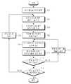
도 3은 본 발명의 오차 보정 테이블 기반의 컬러 변환 과정의 개략적인 전체 흐름도3 is a schematic overall flowchart of a color conversion process based on an error correction table according to the present invention;
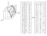
도 4는 본 발명의 오차 보정 테이블 기반의 컬러 변환 동작 수행을 위한 RGB용 오차 보정 테이블의 예시도4 is an exemplary diagram of an error correction table for RGB for performing a color conversion operation based on the error correction table of the present invention.
도 5는 본 발명의 오차 보정 테이블 기반의 컬러 변환 동작 수행을 위한 오차 보정값의 포맷 예시도5 is an exemplary format of an error correction value for performing a color conversion operation based on an error correction table according to the present invention.
도 6은 본 발명의 오차 보정 테이블 기반의 컬러 변환 동작 중 오차 보정 테이블 생성 동작의 전체 흐름도6 is an overall flowchart of an error correction table generation operation during an error correction table based color conversion operation of the present invention.
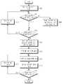
도 7은 도 6 중 오차 보정 테이블 생성 동작의 상세 흐름도7 is a detailed flowchart of an error correction table generation operation in FIG. 6.
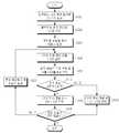
도 8은 도 6 중 오차 보정 테이블 압축 동작의 상세 흐름도8 is a detailed flowchart of an error correction table compression operation of FIG. 6.
도 9는 도 6의 동작 수행에 따른 오차 보정값의 압축 상태의 일 예시도9 is an exemplary diagram of a compressed state of an error correction value according to the operation of FIG. 6.
도 10은 본 발명의 오차 보정 테이블 기반의 컬러 변환 동작 중 오차 보정 동작의 상세 흐름도10 is a detailed flowchart of an error correction operation among color conversion operations based on an error correction table according to the present invention.
본 발명은 적절한 표시장치 또는 출력장치에 표시/출력해야할 컬러를 생성하기 위해 컬러 룩업 테이블(CLUT: Color Look-Up Table) 등과 같은 오차 보정 테이블을 이용하여 컬러를 변환하는 방법에 관한 것이다.The present invention relates to a method of converting colors using an error correction table, such as a color look-up table (CLUT), to produce a color to be displayed / output on a suitable display or output device.
스캐너, 프린터, 모니터, 또한 최근 들어서는 모바일 LCD 등과 같은 컬러를 재현하는 다양한 장치는 사용자들의 다양한 요구를 충족시키기 위해, 그 기능의 다양화, 고품질화, 그리고 저가격화 되어가고 있으며, 각각의 사용 분야에 따라 서로 다른 색공간(color space), 또는 컬러 모델을 사용하고 있다. 예컨대, 컴퓨터 모니터를 사용하는 분야에서는 RGB 색공간을 사용하고, 인쇄분야에서는 CMYK(Cyan-Magenta-Yellow-Black) 색공간을 사용한다. 또한 어느 장치에서나 정확하게 재생될 수 있는, 이른바 장치 독립적 컬러를 정의하기 위해 CIE(Commission Internationable de I'Eclairage) 색공간이 사용되기도 한다. CIE 색공간은 CIE-XYZ, CIE L*a*b*, CIE LUV 색공간 등으로 분류될 수 있다. CIE 색공간은 컴퓨터에서 사용하기 쉽고 광범위한 컬러를 표현할 수 있기 때문에 널리 사용되고 있다.Various devices that reproduce colors such as scanners, printers, monitors, and mobile LCDs in recent years are becoming more diversified, higher quality, and lower cost in order to meet the various needs of users. Different color spaces or color models are used. For example, an RGB color space is used in the field of using a computer monitor, and a Cyan-Magenta-Yellow-Black (CMYK) color space is used in the field of printing. In addition, the Commission Internationable de I'Eclairage (CIE) color space is used to define so-called device independent colors that can be reproduced accurately on any device. The CIE color space may be classified into CIE-XYZ, CIE L * a * b *, CIE LUV color space, and the like. The CIE color space is widely used because it is easy to use on a computer and can express a wide range of colors.
디지털 영상에서의 색의 표현은 RGB 컬러 모델이 주로 사용되지만 RGB 컬러 모델은 장치 독립적이지 않으며, 정확한 색보정이 어려우므로, 이를 CIE L*a*b* 컬러 모델 등으로 변환하는 컬러 변환 작업이 통상적으로 수행된다.The RGB color model is mainly used for the representation of color in digital images, but the RGB color model is not device independent, and since it is difficult to accurately correct the color, a color conversion operation for converting the color into a CIE L * a * b * color model or the like is common. Is performed.
통상적으로 컬러 변환 기법들은 CLUT(Color Look-Up Table) 기반 보간이나 다항 회귀 방정식 등과 같은 간단한 형태의 근사 방식을 사용한다. 즉, 야외시인성, 선호색, 'Contrast/Detail Enhancement' 등의 다양한 컬러 변환 알고리즘에서 정의하는 일반적인 컬러 변환을 위한 수식들은 초기에 복잡한 수학 공식으로 정의되어 있다. 따라서, 이를 그대로 적용하여 실제 제품에 구현하기에는 매우 어려우므로 보다 단순한 계산이 가능하도록 상기와 같은 다항 회귀 방정식이나 CLUT 기반의 보간을 이용한 근사 기법을 통상적으로 사용하고 있다. 이는 변환에 필요한 저장 공간을 줄이고, 변환 속도를 높이게 된다. 도 1을 참조하면, 가장 널리 사용되는 근사 기법의 컬러 변환 기법인 CLUT 기반 보간은 다음과 같이 동작한다. 우선 전체 컬러 공간의 변환 중에서 일부분을 샘플링하여 CLUT 형태로 저장하고, 테이블에 저장되지 않은 나머지 컬러들은 다양한 방식의 보간 방식(tetrahedral interpolation, trilinear 등)을 사용하여 변환한다. 반면 다항 회귀 방정식 기법의 경우, 하기 표 1에서와 같이, 복잡한 형태의 원래 변환식을 단순한 형태의 다항 방정식으로 근사화하여 컬러 변환에 사용한다.Typically, color conversion techniques use a simple form of approximation, such as color look-up table (CLUT) based interpolation or polynomial regression equations. That is, general color conversion equations defined by various color conversion algorithms such as outdoor visibility, preferred color, and 'contrast / detail enhancement' are initially defined as complex mathematical formulas. Therefore, since it is very difficult to apply it as it is to a real product, the above polynomial regression equation or approximation method using CLUT-based interpolation is commonly used to enable simpler calculation. This reduces the storage space required for the conversion and speeds up the conversion. Referring to FIG. 1, CLUT based interpolation, a color conversion technique of the most widely used approximation technique, operates as follows. First, a part of the conversion of the entire color space is sampled and stored in the form of CLUT, and the remaining colors not stored in the table are converted using various interpolation methods (tetrahedral interpolation, trilinear, etc.). On the other hand, in the case of the polynomial regression equation technique, as shown in Table 1 below, the original transform equation of a complex form is approximated to a simple polynomial equation and used for color transformation.

일반적으로 CLUT 기반 보간은 큰 저장 공간이 필요하지만 정확도가 높고 빠르며, 다항 회귀 방정식은 작은 저장 공간이 요구되지만 정확도가 낮고 느린 편이다.In general, CLUT-based interpolation requires a large amount of storage space, but is more accurate and faster. Polynomial regression equations require less storage space but are less accurate and slower.
한편 전체 컬러 공간 변환에 대한 맵핑 테이블을 사용할 수도 있는데, 일반적으로 사용되는 24비트 컬러 형식의 경우에 224X 3 = 48M 바이트의 메모리가 요구되므로, 실제 구현에 적용하기에는 너무 크다. 반면 16비트 컬러 형식의 경우에는 216X 2 = 128K 바이트가 요구되므로 구현이 용이할 수 있다.On the other hand, a mapping table for full color space conversion can also be used, which is too large for a practical implementation, since a typical 24-bit color format requires 224
CLUT 기반 보간과 다항 회귀 방정식의 경우 간단한 근사 기법을 사용하므로, 근사 기법을 사용하지 않은 원래의 복잡한 변환식에 비하여 큰 오차가 발생한다. 이에 따라 기존의 방식들에서 이러한 오차를 줄이기 위한 여러 방법들이 제안되고 왔다.CLUT-based interpolation and polynomial regression equations use a simple approximation technique, resulting in a large error compared to the original complex transformation without the approximation technique. Accordingly, various methods have been proposed to reduce such errors in existing methods.
따라서, 본 발명의 목적은 비교적 작은 저장 공간을 필요로 하면서, 동시에 변환 오차를 줄이기 위한 수 있는 오차 보정 테이블 기반의 컬러 변환 방법을 제공함에 있다.Accordingly, an object of the present invention is to provide a color conversion method based on an error correction table that can reduce a conversion error while requiring a relatively small storage space.
상기한 목적을 달성하기 위하여 본 발명은 오차 보정 테이블 기반의 컬러 변환 방법에 있어서, 근사 기법을 사용하여 컬러를 변환하는 과정과, 미리 설정된, 원 변환식과 상기 근사 기법을 이용하여 얻어진 각 컬러의 채널간 차이 정보를 저장하는 오차 보정 테이블을 이용하여, 상기 변환한 컬러의 오차를 보정하는 과정을 포함함을 특징으로 한다.In order to achieve the above object, the present invention provides a color conversion method based on an error correction table, comprising: a process of converting colors using an approximation technique, and a channel of each color obtained by using a predetermined circle conversion equation and the approximation technique. And correcting an error of the converted color by using an error correction table for storing the difference information.
바람직하게는, 상기 오차 보정 테이블은 컬러의 각 채널별로 설정되며, 상기 오차 보정 테이블에는 변환되는 컬러 공간 전체에 대한 오차 보정값들이 저장되며, 상기 오차 보정값은 상기 원 변환식과 상기 근사 기법을 이용하여 얻어진 컬러의 채널 간 차이에 의해 얻어지며, 부호 및 오차 변위 값 저장 필드에 저장됨을 특징으로 한다.Preferably, the error correction table is set for each channel of color, and the error correction table stores error correction values for the entire color space to be converted, and the error correction value uses the circle conversion equation and the approximation technique. It is obtained by the difference between the channels of the obtained color, characterized in that stored in the sign and error displacement value storage field.
이하 본 발명에 따른 바람직한 실시예를 첨부한 도면을 참조하여 상세히 설명한다. 하기 설명에서는 구체적인 구성 소자 등과 같은 특정 사항들이 나타나고 있는데 이는 본 발명의 보다 전반적인 이해를 돕기 위해서 제공된 것일 뿐 이러한 특정 사항들이 본 발명의 범위 내에서 소정의 변형이나 혹은 변경이 이루어질 수 있음은 이 기술분야에서 통상의 지식을 가진 자에게는 자명하다 할 것이다.Hereinafter, exemplary embodiments of the present invention will be described in detail with reference to the accompanying drawings. In the following description, specific details such as specific components are shown, which are provided to help a more general understanding of the present invention, and it is understood that these specific details may be changed or changed within the scope of the present invention. It is self-evident to those of ordinary knowledge in Esau.
도 2는 본 발명의 오차 보정 테이블 기반의 컬러 변환 방식이 적용되는 수행하는 일 예시 컬러 변환 장치의 개략적인 블록 구성도로서, 도 2에 도시된 바와 같이, 크게 입력 장치(10), 화상 처리 장치(20), 표시 장치(30)로 구성될 수 있다. 입력 장치(10)는 적절한 화상 데이터를 생성하고 생성한 화상 데이터를 화상 처리 장치(20)로 전송한다. 화상 처리 장치(20)는 이를 표시 장치(30)에서 표시될 수 있도록 컬러 변환, 보정 등과 같은 처리를 수행하여 표시 장치(30)로 출력한다.FIG. 2 is a schematic block diagram of an exemplary color conversion apparatus to which an error correction table based color conversion scheme of the present invention is applied. As shown in FIG. 2, the
화상 처리 장치(20)는 인터페이스(21)와, ROM(22), 메인 메모리(23), 화상 메모리(25), CPU(24), 화상 출력부(26)로 구성될 수 있다.The
인터페이스(21)는 입력 장치(10)와의 인터페이스를 수행하면, CPU(24)는 인터페이스(21)를 통해 입력 장치(10)로부터 입력되는 화상 데이터를 취득하고, 취득한 화상 데이터를 메인 메모리(23)에 일차적으로 저장한다. ROM(22)은 CPU(24)의 화상 처리 동작을 비롯한 각종 동작 수행에 필요한 프로그램 등을 미리 저장한다. CPU(24)는 화상 처리 장치(20)의 전체 동작을 총괄적으로 제어하며, 특히 메인 메모리(23)에 일차적으로 저장된 화상 데이터를 적절한 처리 동작을 거쳐 화상 메모리(25)에 저장한다. 화상 출력부(26)는 화상 메모리(25)에 저장된 화상 데이터를 적절한 신호 변환 동작을 수행하여 비디오 신호를 생성하고 이를 표시 장치(30)로 출력한다.When the
이때 상기 화상 메모리(25)에는 화상 데이터를 저장하기 위한 화상 데이터 영역(251)과, 컬러 룩업 테이블(CLUT) 영역(252)이 구비되어 있으며, CPU(24)는 화상 데이터 영역(251)의 화상 데이터가 가리키는 CLUT 영역(252)의 CLUT의 컬러 정보에 따라 적절한 컬러 변환 동작을 수행한다.In this case, the
도 3은 본 발명의 오차 보정 테이블 기반의 컬러 변환 과정의 개략적인 전체 흐름도로서, 도 3을 참조하면, 본 발명의 컬러 변환 과정은 크게 두 과정으로 구성된다. 먼저 261과정에서, CLUT 기반 보간이나 다항 회귀 방정식과 같은 기존의 일반적인 근사 기법을 사용하여 컬러를 변환하고, 이후 262과정에서 본 발명의 특징에 따른 오차 보정 동작을 수행하여 변환된 컬러의 오차를 감소시킨다.FIG. 3 is a schematic overall flowchart of an error correction table based color conversion process of the present invention. Referring to FIG. 3, the color conversion process of the present invention is largely composed of two processes. First, in
상기 오차 보정 과정에서 도 4에 도시된 바와 같이, 컬러의 각 채널(예, R, G, B)마다 하나의 오차 보정 테이블을 사용한다. 이때 각 테이블에는 변환되는 컬러 공간 전체에 대한 오차 보정값들이 저장되며, 변위 비트수가 필드 정보로서 추가된다. 오차 보정값은 근사 기법을 사용하지 않은 원래의 변환식과 근사 기법 양자를 통하여 얻어진 컬러의 채널 간 차이를 구하여 얻어지는데, 도 5에 도시된 바와 같이, 부호와 변위로 나누어서 저장된다.In the error correction process, as shown in FIG. 4, one error correction table is used for each channel (eg, R, G, and B) of color. In this case, error correction values for the entire color space to be converted are stored in each table, and the number of displacement bits is added as field information. The error correction value is obtained by obtaining the difference between the channels of the color obtained through both the original conversion formula and the approximation technique without using the approximation technique, as shown in FIG.
오차 보정값을 얻는 방식은 하기 변환 알고리즘과 같다. 하기 알고리즘에서'CH1'은 근사 기법을 사용하지 않은 원래 변환식으로 구한 컬러의 현재 채널값이고, 'CH2'는 근사 방식으로 구한 컬러의 채널값이다.The method of obtaining the error correction value is the same as the following conversion algorithm. In the following algorithm, 'CH1' is the current channel value of the color obtained by the original conversion equation without using the approximation technique, and 'CH2' is the channel value of the color obtained by the approximation method.
[변환 알고리즘][Transformation Algorithm]
if (CH1 >= CH2)if (CH1> = CH2)
부호 = 0Sign = 0
변위 = CH1 - CH2Displacement = CH1-CH2
elseelse
부호 = 1Sign = 1
변위 = CH2 - CH1Displacement = CH2-CH1
도 6은 본 발명의 오차 보정 테이블 기반의 컬러 변환 동작 중 테이블 생성 동작의 전체 흐름도이다. 도 6을 참조하면, 본 발명에 따른 오차 보정 테이블 생성 동작은 먼저 60단계에서 각 채널 별로 상기 근사 기법을 사용하지 않은 원래의 변환식과 근사 기법 양자를 통하여 얻어진 컬러의 채널 간 차이를 구하여 오차 보정값을 얻음으로써 오차 보정 테이블을 생성하고, 이후 61단계에서 상기 생성한 오차 보정 테이블을 적절히 압축하는 오차 보정 테이블 압축 동작을 수행한다.6 is a flowchart illustrating an operation of generating a table during the color conversion operation based on the error correction table according to the present invention. Referring to FIG. 6, an error correction table generation operation according to the present invention first calculates an error correction value by obtaining a difference between channels of a color obtained through both an original conversion formula and an approximation technique that do not use the approximation technique for each channel in
도 7은 도 6 중 오차 보정 테이블 생성 동작의 상세 흐름도로서, 상기 변환 알고리즘에 따른 오차 보정 테이블을 생성하는 동작을 도시되고 있다. 도 7을 참조하면, 먼저 702단계에서는 현재 컬러를 0번 컬러로 설정한다. 이후 804단계에서는 근사 방식으로 출력 컬러 C1을 계산한다. 이후 806단계에서는 원래 방식으로 출력 컬러 C2를 계산한다. 이후 708단계에서는 첫 번째 채널을 현재 채널로 설정한다. 이후 710단계에서는 상기 C1, C2로부터 현재 채널의 오차를 계산한다. 이후 712단계에서는 현재 채널의 오차 보정 테이블에 순차적으로 오차 값을 저장한다. 이후 714단계에서는 현재 채널이 마지막 채널인지 확인하여 마지막 채널이 아닐 경우에는 716단계로 진행하여 현재 채널을 다음 채널로 설정한 후 상기 710단계로 진행하여 C1, C2로부터 현재 채널의 오차를 계산하는 상기의 과정을 반복진행한다. 한편, 상기 714단계에서 판단결과 현재 채널이 마지막 채널일 경우에는 718단계로 진행한다. 718단계에서는 현재 컬러가 마지막 컬러인지를 확인하여 마지막 컬러일 경우에는 종료하며, 마지막 컬러가 아닐 경우에는 720단계로 진행하여 현재 컬러를 1증가 시킨 후 상기 704단계로 진행하여 상기의 과정을 반복진행한다.FIG. 7 is a detailed flowchart of an error correction table generation operation in FIG. 6, and illustrates an operation of generating an error correction table according to the conversion algorithm. Referring to FIG. 7, in
상기 도 7에 도시된 오차 보정 테이블 생성 동작에 따라, 근사 방식의 출력 컬러를 C1, 근사 기법을 사용하지 않은 원래 변환식의 출력 컬러를 C2, C1의 현재 채널 값을 CH1, C2의 현재 채널 값을 CH2라고 가정할 때, CH2 - CH1로 정의되는 오차값 E가 계산되어 저장된다. 이때 오차값. E가 음수이면 부호 비트는 1, 양수이거나 0이면 부호 비트를 0으로 저장하며, 오차값 E의 절대값이 변위 값으로 저장된다.According to the error correction table generation operation shown in FIG. 7, the output color of the original conversion equation without using the approximation method is C1, and the current channel value of C2, C1 is replaced with the current channel value of CH1, C2. Assuming CH2, the error value E defined as CH2-CH1 is calculated and stored. Where error value. If E is negative, the sign bit is 1; if positive or 0, the sign bit is stored as 0, and the absolute value of the error value E is stored as the displacement value.
도 8은 도 6 중 오차 보정 테이블 압축 동작의 상세 흐름도이다. 도 8을 참조하면, 먼저 802단계에서 현재 컬러를 0번 컬러로 설정한다. 이후 804단계에서 현재 컬러의 오차 변위가 저장된 최대 변위 비트 수(현재는 저장된 값이 없음)와 비교하여 최대인지를 확인한다. 확인결과 최대가 아닐 경우에는 이후 808단계로 진행하며, 최대일 경우에는 806단계로 진행한다. 806단계에서는 현재 오차 변위의 비트 수를 최대 변위 비트 수로 설정하고 이후 808단계로 진행한다. 808단계에서는 현재 컬러가 마지막 컬러인지를 확인하여 마지막 컬러가 아닐 경우는 810단계로 진행하여 현재 컬러를 1증가 시킨 후 상기 804단계로 진행하여 상기의 과정을 반복 진행하며 현재 컬러가 마지막 컬러일 경우에는 812단계로 진행한다.8 is a detailed flowchart of an error correction table compression operation of FIG. 6. Referring to FIG. 8, first, a current color is set to
812단계에서는 최대 변위 비트수에 맞추어 압축된 오차 보정 테이블을 생성한다. 이후 814단계에서는 현재 컬러를 0번 컬러로 설정하고, 이후 816단계에서 상기 압축된 오차 보정 테이블로 현재 컬러의 부호를 복사한다. 이후 818단계에서는 상기 압축된 보정 테이블로 현재 컬러의 변위를 복사한다. 이후 819단계에서는 현재 컬러가 마지막 컬러인지를 확인하여 마지막 컬러일 경우에는 종료하며, 마지막 컬러가 아닐 경우는 820단계로 진행하여 현재 컬러를 1 증가 시킨 후 상기 816단계로 진행하여 상기의 과정을 반복 진행한다.In
상기 도 7 및 도 8에 도시된 오차 보정 테이블의 생성 및 압축 동작을 살펴보면, 먼저 도 7에서와 같이, 일차적으로 생성되는 오차 보정 테이블의 경우, 입력 컬러에서 현재 채널이 차지하는 비트수에 부호 1비트를 더한 값을 한 필드의 크기로 한다. 이렇게 필드 크기를 설정함으로써 오차 값이 필드 크기보다 커서 테이블에 저장될 수 없는 경우를 방지할 수 있다. 그리고, 도 8에서와 같이, 이차적으로 상기 생성된 오차 보정 테이블의 최대 오차 변위 값에 맞도록 필드 크기를 조절함으로써 테이블을 압축한다. 이러한 필드 크기의 변화는 아래 식으로 표현된다.Referring to the generation and compression operations of the error correction table shown in FIGS. 7 and 8, first, as shown in FIG. 7, in the case of the error correction table that is primarily generated, a
압축 후 필드 크기 = (최대 오차 변위의 비트수) + (부호 비트 1)Field size after compression = (number of bits of maximum error displacement) + (sign bit 1)
예를 들어, 도 9에 도시된 바와 같이, RGB565 형식에서 G 채널의 최대 오차 변위가 7인 경우, G 채널 테이블의 필드 크기는 압축 전에 7비트이고 압축 후에 4비트일 수 있다.For example, as shown in FIG. 9, when the maximum error displacement of the G channel in the RGB565 format is 7, the field size of the G channel table may be 7 bits before compression and 4 bits after compression.
도 10은 본 발명의 오차 보정 테이블 기반의 컬러 변환 동작 중 오차 보정 동작의 상세 흐름도로서, 도 3에 도시된 262과정의 오차 보정 과정 중 수행될 수 있다. 도 10을 참조하면, 먼저 1002단계에서 입력되는 근사 출력 컬러를 C1로 설정하고, 이후 1004단계에서는 출력되는 보정 컬러를 C2로 설정한다. 이후 1006단계에서는 첫 번째 채널을 현재 채널로 설정한다. 이후 1008단계에서는 C1의 현재 채널 값을 CH로 설정한다. 이후 1010단계에서는 현재 채널의 오차 보정 값 E를 상기 도 6 내지 도 8에 도시된 동작에 의해 미리 저장된 오차 보정 테이블에서 얻는다. 이후 1012단계에서는 E의 부호 비트가 0인지 확인하여 부호 비트가 0일 경우에는 이후 1014단계로 진행하고 부호비트가 0이 아닐 경우(즉 1일 경우)에는 1018단계로 진행한다. 1014단계에서는 C2의 현재 채널 값을 CH + (E의 변위)로 설정하고 이후 1016단계로 진행한다. 1018단계에서는 C2의 현재 채널 값을 CH - (E의 변위)로 설정하고 이후 1016단계로 진행한다. 1016단계에서는 현재 채널이 마지막 채널인지 확인하여 마지막 채널일 경우에는 종료하며, 마지막 채널이 아닐 경우에는 1020단계로 진행한다. 1020단계에서는 현재 채널을 다음 채널로 설정한 후 상기 1008단계로 진행하여 상기의 과정을 반복진행한다.FIG. 10 is a detailed flowchart of an error correction operation during the color conversion operation based on the error correction table of the present invention, and may be performed during the error correction process of
이러한 도 10에 도시된 바와 같은 과정을 수행함으로, 근사 출력 컬러의 각 채널에 대하여 오차 보정 테이블로부터 얻은 값을 더하거나 뺌으로써, 최종적인 보정 출력 컬러를 얻게 된다.By performing the process as shown in FIG. 10, the final corrected output color is obtained by adding or subtracting values obtained from the error correction table for each channel of the approximate output color.
상기와 같이 본 발명의 일 실시예에 따른 오차 보정 테이블 기반의 컬러 변환 동작이 이루어질 수 있다. 상기한 본 발명에 따른 오차 보정 테이블 기반의 컬 러 변환 방식은 기존 근사 기법의 후처리부에 테이블 기반의 오차 보정 단계를 추가함으로써 간단한 근사 기반의 컬러 변환 기법들에서 발생하는 오차를 줄이도록 한다. 이러한 본 발명에 따른 오차 보정 테이블 기반의 컬러 변환 방식은 전체 컬러 공간 변환에 대한 맵핑 테이블을 사용함으로써 대체될 수도 있다. 그러나 예를 들어 16비트 형식에 대한 전체 맵핑에서는 128K 바이트의 테이블 저장 공간이 필요하지만, 본 발명에 따르면 오차값만 저장하므로 상기 전체 컬러 공간 변환에 대한 맵핑 테이블의 사용시보다 절반 이하의 테이블 저장 공간이 요구될 것으로 예상된다.As described above, an error correction table based color conversion operation according to an embodiment of the present invention may be performed. The color correction scheme based on the error correction table according to the present invention reduces the errors occurring in simple approximation-based color conversion techniques by adding a table-based error correction step to the post-processing unit of the existing approximation technique. The error correction table based color conversion scheme according to the present invention may be replaced by using a mapping table for full color space conversion. However, for example, although the entire mapping to the 16-bit format requires 128K bytes of table storage space, the present invention stores only error values, so that less than half of the table storage space is used when using the mapping table for the full color space conversion. It is expected to be required.
한편 상기한 본 발명의 설명에서는 구체적인 실시예에 관해 설명하였으나 여러 가지 변형이 본 발명의 범위를 벗어나지 않고 실시될 수 있다. 따라서 본 발명의 범위는 설명된 실시예에 의하여 정할 것이 아니고 청구범위와 청구범위의 균등한 것에 의하여 정하여져야 할 것이다.Meanwhile, in the above description of the present invention, specific embodiments have been described, but various modifications may be made without departing from the scope of the present invention. Therefore, the scope of the present invention should not be defined by the described embodiments, but by the claims and equivalents of the claims.
상기한 바와 같이, 본 발명에 따른 오차 보정 테이블 기반의 컬러 변환 방식은 전체 컬러 공간의 맵핑 테이블을 사용하는 변환 기법에 비하여 필요한 저장 공간을 절반 이하로 줄일 수 있으며, 단순한 근사법을 사용하는 변환 기법보다 더욱 높은 정밀도의 컬러 변환을 지원할 수 있는 효과를 가질 수 있다. 이러한 본 발명에 따른 컬러 변환 방식은 모바일 LCD와 같이 16비트 컬러 형식을 사용하는 장치에 적용될 경우에 더욱 효과적일 수 있다.As described above, the color correction scheme based on the error correction table according to the present invention can reduce the required storage space to less than half compared to the conversion scheme using the mapping table of the entire color space, and compared to the conversion scheme using the simple approximation. It can have an effect that can support a higher precision color conversion. The color conversion scheme according to the present invention may be more effective when applied to a device using a 16-bit color format, such as a mobile LCD.
Claims (6)
Translated fromKoreanPriority Applications (2)
| Application Number | Priority Date | Filing Date | Title |
|---|---|---|---|
| KR1020060007438AKR100834615B1 (en) | 2006-01-24 | 2006-01-24 | Color conversion method based on error correction table |
| US11/635,114US8559054B2 (en) | 2006-01-24 | 2006-12-07 | Color conversion method based on error correction table |
Applications Claiming Priority (1)
| Application Number | Priority Date | Filing Date | Title |
|---|---|---|---|
| KR1020060007438AKR100834615B1 (en) | 2006-01-24 | 2006-01-24 | Color conversion method based on error correction table |
Publications (2)
| Publication Number | Publication Date |
|---|---|
| KR20070077707A KR20070077707A (en) | 2007-07-27 |
| KR100834615B1true KR100834615B1 (en) | 2008-06-02 |
Family
ID=38285204
Family Applications (1)
| Application Number | Title | Priority Date | Filing Date |
|---|---|---|---|
| KR1020060007438AExpired - Fee RelatedKR100834615B1 (en) | 2006-01-24 | 2006-01-24 | Color conversion method based on error correction table |
Country Status (2)
| Country | Link |
|---|---|
| US (1) | US8559054B2 (en) |
| KR (1) | KR100834615B1 (en) |
Families Citing this family (1)
| Publication number | Priority date | Publication date | Assignee | Title |
|---|---|---|---|---|
| KR102353632B1 (en) | 2014-12-02 | 2022-01-20 | 삼성디스플레이 주식회사 | Polarziation member and display apparatus having the same |
Citations (6)
| Publication number | Priority date | Publication date | Assignee | Title |
|---|---|---|---|---|
| JPH10200770A (en) | 1997-01-13 | 1998-07-31 | Sharp Corp | Color correction method for image data |
| JP2000324348A (en) | 1999-05-07 | 2000-11-24 | Sharp Corp | Image processing method, color correction table, and image processing device |
| KR20020041698A (en)* | 2000-11-28 | 2002-06-03 | 정정휘 | Method for correcting color difference influenced by scanner characteristic and computer readable medium stored thereon computer executable instruction for performing the method |
| JP2003219191A (en) | 2002-01-21 | 2003-07-31 | Sharp Corp | Image processing apparatus and image forming apparatus using the same |
| JP2005249820A (en) | 2004-03-01 | 2005-09-15 | Seiko Epson Corp | Color correction circuit and image display device having the same |
| JP2005249821A (en) | 2004-03-01 | 2005-09-15 | Seiko Epson Corp | Color correction circuit and image display device having the same |
Family Cites Families (28)
| Publication number | Priority date | Publication date | Assignee | Title |
|---|---|---|---|---|
| US5307088A (en)* | 1984-03-21 | 1994-04-26 | Hitachi, Ltd. | Method and apparatus of encoding color image information |
| US4749983A (en)* | 1986-04-29 | 1988-06-07 | International Business Machines Corporation | Compression of multilevel signals |
| EP0273398B1 (en)* | 1986-12-25 | 1995-02-08 | Konica Corporation | Method of correcting color images |
| US5321797A (en)* | 1990-06-11 | 1994-06-14 | Eastman Kodak Company | Apparatus and method for performing coordinate transformation employing stored values and interpolation |
| DE4305693C2 (en)* | 1992-04-06 | 1996-12-19 | Hell Ag Linotype | Color calibration procedure |
| JP3399657B2 (en)* | 1994-09-21 | 2003-04-21 | 富士写真フイルム株式会社 | Image reproduction apparatus and method |
| US5739927A (en)* | 1995-06-07 | 1998-04-14 | Xerox Corporation | Method for refining an existing printer calibration using a small number of measurements |
| US6330075B1 (en)* | 1995-08-03 | 2001-12-11 | Canon Kabushiki Kaisha | Image processing method and apparatus |
| US6049399A (en)* | 1997-11-04 | 2000-04-11 | Winbond Electronics Corp. | Method and apparatus with reduced look-up tables for converting luminance-chrominance color space signals to RGB color space signals |
| EP0940994B1 (en)* | 1998-03-06 | 2014-04-16 | Canon Kabushiki Kaisha | Image processing apparatus and method and storage medium storing steps realizing such method |
| JP4191854B2 (en)* | 1999-08-20 | 2008-12-03 | 東芝テック株式会社 | Color image processing device |
| US6809837B1 (en)* | 1999-11-29 | 2004-10-26 | Xerox Corporation | On-line model prediction and calibration system for a dynamically varying color reproduction device |
| JP3821650B2 (en)* | 2001-01-17 | 2006-09-13 | 三菱電機株式会社 | Color conversion characteristic determination method, image display device, and recording medium |
| KR20030078895A (en)* | 2001-01-25 | 2003-10-08 | 일진다이아몬드 주식회사 서울지사 | Image compensation methods and apparatus using correction zones |
| US7417771B2 (en)* | 2001-06-26 | 2008-08-26 | Sharp Laboratories Of America, Inc. | Error diffusion halftoning system |
| JP3712057B2 (en)* | 2001-08-30 | 2005-11-02 | セイコーエプソン株式会社 | Color conversion table creation method, color conversion table creation device, color conversion table creation program, color conversion device, and printing device |
| US20030063084A1 (en)* | 2001-09-28 | 2003-04-03 | Burke Gregory Michael | System and method for improving 3D data structure representations |
| JP2003116018A (en)* | 2001-10-05 | 2003-04-18 | Hitachi Ltd | Image processing apparatus and image processing method |
| US6775633B2 (en)* | 2001-12-31 | 2004-08-10 | Kodak Polychrome Graphics, Llc | Calibration techniques for imaging devices |
| JP3823858B2 (en)* | 2002-03-20 | 2006-09-20 | セイコーエプソン株式会社 | Correction method of color image data using correction table |
| JP3987414B2 (en)* | 2002-03-29 | 2007-10-10 | 富士通株式会社 | Color conversion device |
| US6781596B2 (en)* | 2002-05-24 | 2004-08-24 | Electronics For Imaging, Inc. | Methods and apparatus for converting color values |
| JP3962642B2 (en)* | 2002-07-08 | 2007-08-22 | キヤノン株式会社 | Image processing apparatus and method |
| US7231084B2 (en)* | 2002-09-27 | 2007-06-12 | Motorola, Inc. | Color data image acquistion and processing |
| KR100710302B1 (en)* | 2005-05-17 | 2007-04-23 | 엘지전자 주식회사 | Apparatus and method for color correction of a display device |
| US20070002380A1 (en)* | 2005-06-30 | 2007-01-04 | Xerox Corporation | Method and system for error compensation |
| JP4676364B2 (en)* | 2006-03-17 | 2011-04-27 | 富士通株式会社 | Color correction method, color correction apparatus, and color correction program |
| US8477371B2 (en)* | 2010-04-29 | 2013-07-02 | Xerox Corporation | Color lookup table generation which minimizes interpolation errors over the entire color space of a color gamut |
- 2006
- 2006-01-24KRKR1020060007438Apatent/KR100834615B1/ennot_activeExpired - Fee Related
- 2006-12-07USUS11/635,114patent/US8559054B2/ennot_activeExpired - Fee Related
Patent Citations (6)
| Publication number | Priority date | Publication date | Assignee | Title |
|---|---|---|---|---|
| JPH10200770A (en) | 1997-01-13 | 1998-07-31 | Sharp Corp | Color correction method for image data |
| JP2000324348A (en) | 1999-05-07 | 2000-11-24 | Sharp Corp | Image processing method, color correction table, and image processing device |
| KR20020041698A (en)* | 2000-11-28 | 2002-06-03 | 정정휘 | Method for correcting color difference influenced by scanner characteristic and computer readable medium stored thereon computer executable instruction for performing the method |
| JP2003219191A (en) | 2002-01-21 | 2003-07-31 | Sharp Corp | Image processing apparatus and image forming apparatus using the same |
| JP2005249820A (en) | 2004-03-01 | 2005-09-15 | Seiko Epson Corp | Color correction circuit and image display device having the same |
| JP2005249821A (en) | 2004-03-01 | 2005-09-15 | Seiko Epson Corp | Color correction circuit and image display device having the same |
Also Published As
| Publication number | Publication date |
|---|---|
| KR20070077707A (en) | 2007-07-27 |
| US20070171445A1 (en) | 2007-07-26 |
| US8559054B2 (en) | 2013-10-15 |
Similar Documents
| Publication | Publication Date | Title |
|---|---|---|
| EP3796666B1 (en) | Video signal processing method and apparatus | |
| RU2648634C1 (en) | Coding and decoding of a perceptionally quantized video content | |
| KR100938846B1 (en) | Color converter and method | |
| JP4068673B2 (en) | Image processing apparatus and method | |
| Mantiuk et al. | Lossy compression of high dynamic range images and video | |
| JP2009055465A (en) | Image processing apparatus and method | |
| WO2003003716A1 (en) | Image processing device, image processing method, program, and recording medium | |
| KR101303874B1 (en) | Apparatus and method for gamut mapping | |
| EP2421241B1 (en) | Print controlling terminal and color correction method | |
| JP2004252620A (en) | Image processing device and method, and program | |
| US6999213B2 (en) | Image processing system, image processing apparatus, image processing method, and storage medium thereof | |
| KR100800699B1 (en) | Color Lookup Table Generation and Color Conversion Method Using the Same | |
| JP2004304793A (en) | Color conversion device and color conversion method | |
| US20080174798A1 (en) | Color-management apparatus and method | |
| JP4250863B2 (en) | Color correction processing method and apparatus | |
| JP2003219176A (en) | Image processing apparatus, image processing system, image processing method, storage medium, and program | |
| KR100834615B1 (en) | Color conversion method based on error correction table | |
| JP4300780B2 (en) | Color conversion coefficient creation method, color conversion coefficient creation apparatus, program, and storage medium | |
| JP2007312313A (en) | Image processor, image processing method and program | |
| JP2008236083A (en) | Image processing apparatus, color conversion method, color conversion table creation method, program, and storage medium | |
| JP2008067313A (en) | Color processing device, color processing method, and program | |
| JP2008072603A (en) | Image processing method | |
| Meininger et al. | Display Calibration | |
| JPWO2007083717A1 (en) | Color conversion matrix creation method and color conversion method | |
| JP3766139B2 (en) | Color image signal processing apparatus and color image signal processing method |
Legal Events
| Date | Code | Title | Description |
|---|---|---|---|
| A201 | Request for examination | ||
| PA0109 | Patent application | St.27 status event code:A-0-1-A10-A12-nap-PA0109 | |
| PA0201 | Request for examination | St.27 status event code:A-1-2-D10-D11-exm-PA0201 | |
| D13-X000 | Search requested | St.27 status event code:A-1-2-D10-D13-srh-X000 | |
| D14-X000 | Search report completed | St.27 status event code:A-1-2-D10-D14-srh-X000 | |
| E902 | Notification of reason for refusal | ||
| PE0902 | Notice of grounds for rejection | St.27 status event code:A-1-2-D10-D21-exm-PE0902 | |
| P11-X000 | Amendment of application requested | St.27 status event code:A-2-2-P10-P11-nap-X000 | |
| P13-X000 | Application amended | St.27 status event code:A-2-2-P10-P13-nap-X000 | |
| PG1501 | Laying open of application | St.27 status event code:A-1-1-Q10-Q12-nap-PG1501 | |
| E902 | Notification of reason for refusal | ||
| PE0902 | Notice of grounds for rejection | St.27 status event code:A-1-2-D10-D21-exm-PE0902 | |
| P11-X000 | Amendment of application requested | St.27 status event code:A-2-2-P10-P11-nap-X000 | |
| P13-X000 | Application amended | St.27 status event code:A-2-2-P10-P13-nap-X000 | |
| E701 | Decision to grant or registration of patent right | ||
| PE0701 | Decision of registration | St.27 status event code:A-1-2-D10-D22-exm-PE0701 | |
| GRNT | Written decision to grant | ||
| PR0701 | Registration of establishment | St.27 status event code:A-2-4-F10-F11-exm-PR0701 | |
| PR1002 | Payment of registration fee | St.27 status event code:A-2-2-U10-U11-oth-PR1002 Fee payment year number:1 | |
| PG1601 | Publication of registration | St.27 status event code:A-4-4-Q10-Q13-nap-PG1601 | |
| PR1001 | Payment of annual fee | St.27 status event code:A-4-4-U10-U11-oth-PR1001 Fee payment year number:4 | |
| PR1001 | Payment of annual fee | St.27 status event code:A-4-4-U10-U11-oth-PR1001 Fee payment year number:5 | |
| R18-X000 | Changes to party contact information recorded | St.27 status event code:A-5-5-R10-R18-oth-X000 | |
| FPAY | Annual fee payment | Payment date:20130429 Year of fee payment:6 | |
| PR1001 | Payment of annual fee | St.27 status event code:A-4-4-U10-U11-oth-PR1001 Fee payment year number:6 | |
| FPAY | Annual fee payment | Payment date:20140429 Year of fee payment:7 | |
| PR1001 | Payment of annual fee | St.27 status event code:A-4-4-U10-U11-oth-PR1001 Fee payment year number:7 | |
| FPAY | Annual fee payment | Payment date:20150429 Year of fee payment:8 | |
| PR1001 | Payment of annual fee | St.27 status event code:A-4-4-U10-U11-oth-PR1001 Fee payment year number:8 | |
| FPAY | Annual fee payment | Payment date:20160428 Year of fee payment:9 | |
| PR1001 | Payment of annual fee | St.27 status event code:A-4-4-U10-U11-oth-PR1001 Fee payment year number:9 | |
| FPAY | Annual fee payment | Payment date:20170427 Year of fee payment:10 | |
| PR1001 | Payment of annual fee | St.27 status event code:A-4-4-U10-U11-oth-PR1001 Fee payment year number:10 | |
| LAPS | Lapse due to unpaid annual fee | ||
| PC1903 | Unpaid annual fee | St.27 status event code:A-4-4-U10-U13-oth-PC1903 Not in force date:20180528 Payment event data comment text:Termination Category : DEFAULT_OF_REGISTRATION_FEE | |
| PC1903 | Unpaid annual fee | St.27 status event code:N-4-6-H10-H13-oth-PC1903 Ip right cessation event data comment text:Termination Category : DEFAULT_OF_REGISTRATION_FEE Not in force date:20180528 | |
| P22-X000 | Classification modified | St.27 status event code:A-4-4-P10-P22-nap-X000 |