KR100833809B1 - Image display element and image display device - Google Patents
Image display element and image display deviceDownload PDFInfo
- Publication number
- KR100833809B1 KR100833809B1KR1020037000053AKR20037000053AKR100833809B1KR 100833809 B1KR100833809 B1KR 100833809B1KR 1020037000053 AKR1020037000053 AKR 1020037000053AKR 20037000053 AKR20037000053 AKR 20037000053AKR 100833809 B1KR100833809 B1KR 100833809B1
- Authority
- KR
- South Korea
- Prior art keywords
- polarization
- light
- optical element
- image display
- polarization selective
- Prior art date
- Legal status (The legal status is an assumption and is not a legal conclusion. Google has not performed a legal analysis and makes no representation as to the accuracy of the status listed.)
- Expired - Fee Related
Links
Images


Classifications
- H—ELECTRICITY
- H04—ELECTRIC COMMUNICATION TECHNIQUE
- H04N—PICTORIAL COMMUNICATION, e.g. TELEVISION
- H04N9/00—Details of colour television systems
- H04N9/12—Picture reproducers
- H04N9/31—Projection devices for colour picture display, e.g. using electronic spatial light modulators [ESLM]
- H04N9/3141—Constructional details thereof
- H04N9/315—Modulator illumination systems
- H04N9/3167—Modulator illumination systems for polarizing the light beam
- G—PHYSICS
- G02—OPTICS
- G02F—OPTICAL DEVICES OR ARRANGEMENTS FOR THE CONTROL OF LIGHT BY MODIFICATION OF THE OPTICAL PROPERTIES OF THE MEDIA OF THE ELEMENTS INVOLVED THEREIN; NON-LINEAR OPTICS; FREQUENCY-CHANGING OF LIGHT; OPTICAL LOGIC ELEMENTS; OPTICAL ANALOGUE/DIGITAL CONVERTERS
- G02F1/00—Devices or arrangements for the control of the intensity, colour, phase, polarisation or direction of light arriving from an independent light source, e.g. switching, gating or modulating; Non-linear optics
- G02F1/01—Devices or arrangements for the control of the intensity, colour, phase, polarisation or direction of light arriving from an independent light source, e.g. switching, gating or modulating; Non-linear optics for the control of the intensity, phase, polarisation or colour
- G02F1/13—Devices or arrangements for the control of the intensity, colour, phase, polarisation or direction of light arriving from an independent light source, e.g. switching, gating or modulating; Non-linear optics for the control of the intensity, phase, polarisation or colour based on liquid crystals, e.g. single liquid crystal display cells
- G—PHYSICS
- G02—OPTICS
- G02B—OPTICAL ELEMENTS, SYSTEMS OR APPARATUS
- G02B5/00—Optical elements other than lenses
- G02B5/32—Holograms used as optical elements
- G—PHYSICS
- G02—OPTICS
- G02F—OPTICAL DEVICES OR ARRANGEMENTS FOR THE CONTROL OF LIGHT BY MODIFICATION OF THE OPTICAL PROPERTIES OF THE MEDIA OF THE ELEMENTS INVOLVED THEREIN; NON-LINEAR OPTICS; FREQUENCY-CHANGING OF LIGHT; OPTICAL LOGIC ELEMENTS; OPTICAL ANALOGUE/DIGITAL CONVERTERS
- G02F1/00—Devices or arrangements for the control of the intensity, colour, phase, polarisation or direction of light arriving from an independent light source, e.g. switching, gating or modulating; Non-linear optics
- G02F1/01—Devices or arrangements for the control of the intensity, colour, phase, polarisation or direction of light arriving from an independent light source, e.g. switching, gating or modulating; Non-linear optics for the control of the intensity, phase, polarisation or colour
- G02F1/13—Devices or arrangements for the control of the intensity, colour, phase, polarisation or direction of light arriving from an independent light source, e.g. switching, gating or modulating; Non-linear optics for the control of the intensity, phase, polarisation or colour based on liquid crystals, e.g. single liquid crystal display cells
- G02F1/133—Constructional arrangements; Operation of liquid crystal cells; Circuit arrangements
- G02F1/1333—Constructional arrangements; Manufacturing methods
- G02F1/1335—Structural association of cells with optical devices, e.g. polarisers or reflectors
- G02F1/133504—Diffusing, scattering, diffracting elements
- G—PHYSICS
- G02—OPTICS
- G02F—OPTICAL DEVICES OR ARRANGEMENTS FOR THE CONTROL OF LIGHT BY MODIFICATION OF THE OPTICAL PROPERTIES OF THE MEDIA OF THE ELEMENTS INVOLVED THEREIN; NON-LINEAR OPTICS; FREQUENCY-CHANGING OF LIGHT; OPTICAL LOGIC ELEMENTS; OPTICAL ANALOGUE/DIGITAL CONVERTERS
- G02F1/00—Devices or arrangements for the control of the intensity, colour, phase, polarisation or direction of light arriving from an independent light source, e.g. switching, gating or modulating; Non-linear optics
- G02F1/01—Devices or arrangements for the control of the intensity, colour, phase, polarisation or direction of light arriving from an independent light source, e.g. switching, gating or modulating; Non-linear optics for the control of the intensity, phase, polarisation or colour
- G02F1/13—Devices or arrangements for the control of the intensity, colour, phase, polarisation or direction of light arriving from an independent light source, e.g. switching, gating or modulating; Non-linear optics for the control of the intensity, phase, polarisation or colour based on liquid crystals, e.g. single liquid crystal display cells
- G02F1/133—Constructional arrangements; Operation of liquid crystal cells; Circuit arrangements
- G02F1/1333—Constructional arrangements; Manufacturing methods
- G02F1/1335—Structural association of cells with optical devices, e.g. polarisers or reflectors
- G02F1/133528—Polarisers
- G—PHYSICS
- G02—OPTICS
- G02F—OPTICAL DEVICES OR ARRANGEMENTS FOR THE CONTROL OF LIGHT BY MODIFICATION OF THE OPTICAL PROPERTIES OF THE MEDIA OF THE ELEMENTS INVOLVED THEREIN; NON-LINEAR OPTICS; FREQUENCY-CHANGING OF LIGHT; OPTICAL LOGIC ELEMENTS; OPTICAL ANALOGUE/DIGITAL CONVERTERS
- G02F1/00—Devices or arrangements for the control of the intensity, colour, phase, polarisation or direction of light arriving from an independent light source, e.g. switching, gating or modulating; Non-linear optics
- G02F1/01—Devices or arrangements for the control of the intensity, colour, phase, polarisation or direction of light arriving from an independent light source, e.g. switching, gating or modulating; Non-linear optics for the control of the intensity, phase, polarisation or colour
- G02F1/13—Devices or arrangements for the control of the intensity, colour, phase, polarisation or direction of light arriving from an independent light source, e.g. switching, gating or modulating; Non-linear optics for the control of the intensity, phase, polarisation or colour based on liquid crystals, e.g. single liquid crystal display cells
- G02F1/133—Constructional arrangements; Operation of liquid crystal cells; Circuit arrangements
- G02F1/1333—Constructional arrangements; Manufacturing methods
- G02F1/1335—Structural association of cells with optical devices, e.g. polarisers or reflectors
- G02F1/1336—Illuminating devices
- G02F1/13362—Illuminating devices providing polarized light, e.g. by converting a polarisation component into another one
- G—PHYSICS
- G03—PHOTOGRAPHY; CINEMATOGRAPHY; ANALOGOUS TECHNIQUES USING WAVES OTHER THAN OPTICAL WAVES; ELECTROGRAPHY; HOLOGRAPHY
- G03B—APPARATUS OR ARRANGEMENTS FOR TAKING PHOTOGRAPHS OR FOR PROJECTING OR VIEWING THEM; APPARATUS OR ARRANGEMENTS EMPLOYING ANALOGOUS TECHNIQUES USING WAVES OTHER THAN OPTICAL WAVES; ACCESSORIES THEREFOR
- G03B21/00—Projectors or projection-type viewers; Accessories therefor
- G03B21/005—Projectors using an electronic spatial light modulator but not peculiar thereto
Landscapes
- Physics & Mathematics (AREA)
- Nonlinear Science (AREA)
- General Physics & Mathematics (AREA)
- Optics & Photonics (AREA)
- Chemical & Material Sciences (AREA)
- Crystallography & Structural Chemistry (AREA)
- Mathematical Physics (AREA)
- Engineering & Computer Science (AREA)
- Multimedia (AREA)
- Signal Processing (AREA)
- Liquid Crystal (AREA)
- Diffracting Gratings Or Hologram Optical Elements (AREA)
- Projection Apparatus (AREA)
- Holo Graphy (AREA)
Abstract
Translated fromKoreanDescription
Translated fromKorean본 발명은 반사형 공간 광변조 소자를 사용한 화상 표시 소자 및 화상 표시 장치에 관한 것으로, 특히, 장치의 경량화, 제조의 저비용화, 표시 화상의 고콘트라스트화를 도모하는 것에 관한 것이다.BACKGROUND OF THE
종래에는 이하에 언급하는 바와 같이, 여러 가지의 화상 표시 소자 및 이들 화상 표시 소자를 사용하여 구성된 화상 표시 장치가 제안되어 있다.Conventionally, as mentioned below, various image display elements and an image display apparatus constructed using these image display elements have been proposed.
〔1〕공간 광변조 소자[1] spatial light modulation elements
공간 광변조 소자(Spatial Light Modulator: SLM)는 영상 신호가 입력되고, 그 신호에 따른 화상 데이터에 기초하여, 각 화소마다 입사광을 변조하도록 구성된 장치이다. 공간 광변조 소자를 투과하는 광을 변조하는 투과형과, 공간 광변조 소자에 있어서 반사되는 광을 변조하는 반사형이 있다.A spatial light modulator (SLM) is a device configured to input an image signal and modulate incident light for each pixel based on the image data according to the signal. There are a transmission type for modulating light passing through the spatial light modulator and a reflection type for modulating light reflected in the spatial light modulator.
반사형 공간 광변조 소자는 액정, 디지털 마이크로 미러 등을 사용하여 구성되어 있다. 특히, 액정을 사용하여 구성한 것은 액정형 공간 광변조 소자라고 불린다.The reflective spatial light modulator is constructed using a liquid crystal, a digital micro mirror, or the like. In particular, what constitutes using a liquid crystal is called a liquid crystal type spatial light modulator.
액정에는 선광(편광 도파) 모드형, 복굴절 모드형, 광산란 모드형, 광흡수 모드형 등이 있다. 일반적으로 사용되는 액정으로서는 선광(편광 도파) 모드형의 트위스티드 네마틱(TN) 동작 모드를 사용하는 TN 액정, 복굴절 동작 모드형의 슈퍼 트위스티드 네마틱(STN) 동작 모드를 사용하는 STN 액정, 및 강유전성 액정(FLC)동작 모드를 사용하는 FLC 형의 액정 등이 있다.Liquid crystals include linear light (polarization waveguide) mode, birefringence mode, light scattering mode, and light absorption mode. Commonly used liquid crystals include TN liquid crystals using a twisted nematic (TN) mode of linear light (polarization waveguide) mode, STN liquid crystals using a super twisted nematic (STN) operating mode of birefringence mode, and ferroelectricity. FLC type liquid crystals using the liquid crystal (FLC) operating mode.
이들 편광 상태를 변조하는 반사형 공간 광변조 소자로는 강유전성 액정 공간 광변조 소자 외에, TN 액정을 사용한 수직 배향 액정 공간 광변조 소자, 반강유전성 액정 공간 광변조 소자, TN 액정을 사용한 복굴절 모드의 공간 광변조 소자 등이 있다.In addition to the ferroelectric liquid crystal spatial light modulators, the reflective spatial light modulators modulating these polarization states include a vertically oriented liquid crystal spatial light modulator using TN liquid crystal, a semiferroelectric liquid crystal spatial light modulator, and a birefringent mode using TN liquid crystal. Light modulation elements;
〔2〕반사형 FLC 공간 광변조 소자[2] reflective FLC spatial light modulation elements
편광 상태를 변조하는 반사형 공간 광변조 소자 중, 반사형 FLC 공간 광변조 소자에 대한 구조와 동작 원리를 설명한다.Among the reflective spatial light modulators modulating the polarization state, the structure and operating principle of the reflective FLC spatial light modulator will be described.
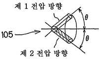
반사형 FLC 공간 광변조 소자는 도 1a, 도 1b 및 도 1c에 도시하는 바와 같이, 한 쌍의 전극부와 그 사이에 삽입된 액정 재료(105)를 갖고서 구성되어 있다. 도면 상측의 전극부는 글래스 기판(101A)과, 그 내측(하측)의 투명전극(102A)과, 그 내측(하측)의 배향막(103A)을 갖고 있다. 도면 중 하측의 전극부는 실리콘 기판(101B)과, 그 내측(상측)의 알루미늄 전극(102B)과, 그 내측(상측)의 배향막(103B)을 갖고 있다. 알루미늄 전극(102B)은 반사막으로서도 기능한다. 상측의 전극부의 글래스 기판(101A)의 외측(상측)에는 편광자(104)가 배치되어 있다.The reflective FLC spatial light modulator is composed of a pair of electrode portions and a
도 1a는 투명전극(102A) 및 알루미늄 전극(102B)에 제 1 방향의 전압이 인가된 제 1 전압 방향 상태를 도시하고, 도 1b는 투명전극(102A) 및 알루미늄 전극(102B)에 제 1 방향과는 반대 방향인 제 2 방향의 전압이 인가된 제 2 전압 방향 상태를 도시하고 있다.FIG. 1A shows a first voltage direction state in which a voltage in a first direction is applied to the
또한, 액정 재료(105)는 도 1c에 도시하는 바와 같이, 제 1 전압 방향 상태에서는 입사편광에 대하여 복굴절 효과를 나타내지 않지만, 제 2 전압 방향 상태에서는 입사편광에 대하여 복굴절 효과를 나타낸다.Further, as shown in FIG. 1C, the
편광자(104)를 통하여 입사한 편광(107A)은 도 1a에 도시하는 제 1 전압 방향 상태에서는 액정 재료(105)가 복굴절 효과를 나타내지 않기 때문에, 이 액정 재료(105)를 투과하고, 편파 상태를 바꾸지 않고서 알루미늄 전극(반사막; 102B)에 도달한다. 그리고, 알루미늄 전극(반사막; 102B)에서 반사된 편광(107B)은 재차 액정 재료(105)를 투과하여, 편파 상태를 바꾸지 않고서 편광자(104)에 도달한다. 즉, 입사광의 편파 상태와 동일한 편파 상태의 광이 편광자(104)로 되돌아오게 된다. 따라서, 알루미늄 전극(반사막; 102B)에서 반사된 반사광이 편광자(104)를 통하여, 출사광으로서 얻어지게 된다.Since the
한편, 도 1b에 도시하는 제 2 전압 방향 상태에서는 편광자(104)를 통하여 입사한 편광(107A)은 액정 재료(105)를 투과함으로써 복굴절 효과를 받아들여 직선편광인 것이 원편광으로 변화한다. 원편광(107B)은 알루미늄 전극(반사막; 102B)에서 반사되고, 이 반사에 의해서 편광의 회전 방향을 반대 방향으로 한다. 회전 방향이 반대로 된 원편광(107B)은 재차 액정 재료(105)를 투과함으로써 복굴절 효과를 받아, 직선편광으로 된다. 이 때의 직선편광은 편광자(104)의 편광 방향과 직교하고, 따라서, 편광자(104)를 통과하지 않는다.On the other hand, in the second voltage direction state shown in FIG. 1B, the polarized
즉, 이 반사형 FLC 공간 광변조 소자에 있어서는 제 1 전압 방향 상태의 부분에 있어서 「백색 표시」로 되고, 제 2 전압 방향 상태의 부분에 있어서 「흑색 표시」로 된다.That is, in this reflective FLC spatial light modulation element, it becomes "white display" in the part of a 1st voltage direction state, and becomes "black display" in the part of a 2nd voltage direction state.
〔3〕반사형 공간 광변조 소자를 사용한 투사형 화상 표시 장치[3] projection-type image display apparatuses using reflective spatial light modulators
일반적인 반사형 공간 광변조 소자, 예를 들면, 반사형 TN 액정 패널을 갖고 구성된 투사형의 화상 표시 장치에 있어서는 도 2에 도시하는 바와 같이, 램프 광원(201)으로부터 사출한 조명광은 광속 단면 형상의 보정, 강도의 균일화, 발산각 제어 등의 기능을 갖는 조명 광학계(202)에 입사한다. 이 조명 광학계(202)에는 도시하지 않는 P-S 편광 변환기를 설치하여도 좋다. 이 P-S 편광 변환기는 무편광 상태의 조명광을, P 편광, 또는 S 편광 중 어느 한쪽의 편광에, 50% 이상의 효율로 일치시키는 기능을 갖는 광학 블록이다.In a projection type image display device having a general reflective spatial light modulator, for example, a reflective TN liquid crystal panel, as shown in FIG. 2, the illumination light emitted from the
여기에 도시한 예에서는 조명 광학계(202)를 통과한 조명광은 지면에 수직인 방향으로 전기 벡터가 진동하는 편광 상태, 즉 적색광을 반사하는 다이크로익 미러(dichroic mirror; 203)의 반사면에 대해서 S 편광으로 되어 있다. 즉, 조명 광학계(202)로부터 사출된 조명광은 적색광을 반사하는 다이크로익 미러(203)에 의해, 적색 성분만이 진행 방향을 90°편향되고, 계속해서 이 적색광은 미러(204)에서 반사되어, 적색광용의 편광 빔 스플리터(이하,「PBS」라고 한다; 210)에 입사한다.In the example shown here, the illumination light passing through the illumination
PBS(210)에 입사한 적색광은 이 PBS(210)의 유전체막(210a)에서 S 편향 성분만이 반사되어, 입사편광으로서 적색광용의 반사형 TN 액정 패널(213)에 입사한다. 이 적색광용의 반사형 TN 액정 패널(213)로써, 편광 상태가 변조되어 반사된 조명광은 재차 PBS(210)의 유전체막(210a)에 입사하고, 여기서 P 편광만이 투과하도록 검파되며, 편광 변조가 휘도 변조로 변환된다. 휘도 변조로 변환된 조명광은 크로스 다이크로익 프리즘(209)에 입사한다.The red light incident on the
한편, 적색광을 반사하는 다이크로익 미러(203)를 투과한 조명광은 계속해서 배치된 녹색광을 반사하는 다이크로익 미러(205)에 입사한다. 이 다이크로익 미러(205)에서는 녹색광만이 반사되고, 나머지의 청색광 성분은 투과된다. 분리된 녹색광 및 청색광은 상술한 적색광의 경우와 마찬가지로, PBS(211, 212)에 의해, S 편광만이 반사되고, 녹색광용의 반사형 TN 액정 패널(214), 청색광용의 반사형 TN 액정 패널(215)에 각각 입사한다.On the other hand, the illumination light transmitted through the
녹색광용의 반사형 TN 액정 패널(214), 청색광용의 반사형 TN 액정 패널(215)로써 편광 상태가 변조되어 반사된 조명광은 재차 PBS(211, 212)의 유전체막(211a, 212a)에 입사하고, 여기서 P 편광만이 투과하도록 검파되고, 편광 변조가 휘도 변조로 변환된다. 휘도 변조로 변환된 사출 광속은 크로스 다이크로익 프리즘(209)에 입사한다.The illumination light reflected by the polarization state is modulated by the reflective TN
이 화상 표시 장치에 있어서는 표시 화상에 따라서, 각 색광용의 반사형 TN 액정 패널(213, 214, 215)에 있어서 각각 변조된 적색광, 녹색광 및 청색광은 크로스 다이크로익 프리즘(209)에서 합성되고, 투사광학계(208)에 입사하여, 스크린(216)상에 결상된다.In this image display device, red light, green light, and blue light modulated in the reflective TN
〔4〕반사형 공간 광변조 소자용 조명 장치[4] illuminators for reflective spatial light modulators
반사형 공간 광변조 소자용의 조명 장치로서, 도 3 및 도 4에 도시하는 바와 같이, 특개평9-189809호 공보에 기재된 조명 장치가 있다. 이 조명 장치에 있어서는 도시하지 않는 조명광원으로부터 방사된 판독광이, 도 3에 도시하는 바와 같이, 커플링 프리즘(305), 글래스 기판(304)을 지나서, 홀로그램 컬러 필터(303r, 303g, 303b)에 입사한다.As a lighting device for a reflective spatial light modulator, there is a lighting device described in Japanese Patent Laid-Open No. 9-189809, as shown in FIGS. 3 and 4. In this lighting apparatus, the read light radiated from the illumination light source which is not shown in figure passes through the
여기서, 303r, 303g, 303b는 각각 적색용, 녹색용, 청색용의 체적 홀로그램 렌즈이고, 미리 레이저 노광에 의해 간섭 줄무늬가 소결된 약 1화소대(大)의 면적을 갖는 각 색광용 미소 렌즈가 적층된 구조로 되어 있다. 1화소대란 R(적색), G(녹색), B(청색)의 각 1화소의 계 3화소가 세트로 된 것이다. 이들 홀로그램 컬러필터(303r, 303g, 303b)는 판독광의 스펙트럼의 적색광, 녹색광, 청색광을 반사형 액정 패널의 커버 글래스(302), 공통전극(318), 배향막(317), 액정층(316), 배향막(315) 및 유전체 미러막(314)을 통해서, 화소 전극층(313)상의 각각 대응하는 색 화소 전극(313r, 313g, 313b)에 집광시킨다.Here, 303r, 303g, and 303b are volume hologram lenses for red, green, and blue, respectively, and each color light microlens having an area of about one pixel band in which interference sintering is sintered by laser exposure is laminated. Structure. One pixel band is a set of three pixels each of one pixel of R (red), G (green), and B (blue). These
그리고, 이 홀로그램 컬러 필터(303r, 303g, 303b)는 입사광의 편광 특성에 관한 의존성을 갖고 있다. 즉, 홀로그램 컬러 필터(303r, 303g, 303b)로의 입사광 중, S 편광이 주로 회절되고, P 편광의 회절 효율은 S 편광보다도 낮아지고 있다. 이것은 「coupled-wavetheory」의 엄밀해(嚴密解)에 의해, 예를 들면, 반사형이 두꺼운 홀로그램의 경우에는 홀로그램의 두께(t)와 홀로그램 내의 간섭 줄무늬의 피치(∧)에 의해 결정되는 값(t/∧)이 1 내지 5인 경우, 도 4에 도시하는 바와 같이, TE(S 편광), TM(P 편광)의 회절 효율에는 차이가 생기고, S 편광은 P 편광과 비교 하여 최대 45% 정도 커지기 때문이다(참고 논문: M. G. Moharam and T. K. Gayload: Rigourous coupled-wave analysis of planar grating diffraction, J. 0pt. Soc. Am. 71, 811-818(1977), M. G. Moharam and T. K. Gayload: Rigourous coupled-wave analysis of grating diffraction E-mode polarization and lossws, J.0pt. Soc. Am. 73, 451-455(1983)).The
홀로그램 컬러 필터(303r, 303g, 303b)에 대하여 비스듬하게 입사한 판독광 중의 S 편광 성분의 광이 주로 회절되어 액정층(316)에 수직으로 입사하고, 이 조명광 중 편광 방향이 90° 변조되어 반사된 광(P 편광 성분)은 상술한 현상에 의해, 회절 효과가 낮기 때문에 거의 회절 작용을 받지 않고서, 홀로그램 컬러 필터(303r, 303g, 303b)로부터 수직으로 사출한다.The light of the S-polarized component in the read light incident obliquely with respect to the
그리고, 유전체 미러막(314)에 의해 반사된 조명광은 도시하지 않는 투사렌즈에 입사되고, 이 투사렌즈에 의해서, 스크린 상에 화상을 결상한다.The illumination light reflected by the
〔5〕편광 선택성 홀로그램 광학 소자[5] polarization selective hologram optical elements
편광 선택성 홀로그램 광학 소자를 실현하는 수법은 몇 개가 있다. 예를 들면, USP5,161,039에 공개되어 있는 바와 같이, 광경화성 수지, 또는 열경화성 수지와 액정 재료를 혼합한 혼합 재료를 글래스 플레이트들 사이에 끼워 밀봉하여 구성한 홀로그램 광학 소자가 있다.There are several methods for realizing a polarization selective hologram optical element. For example, as disclosed in US Pat. No. 5,161,039, there is a holographic optical element constructed by sealing a photocurable resin or a mixed material of a thermosetting resin and a liquid crystal material sandwiched between glass plates.
이것은 다음과 같은 순서로 제작된다. 우선, 상술한 혼합 재료를 봉입한 패널 상에 있어서, 레이저광을 간섭시킨다. 이로써 발생하는 간섭 줄무늬는 명(明)부에서는 광자(photon)가 많이 존재하고, 암(暗)부에서는 광자가 적음으로써 형성되어 있다. 광자의 에너지가 높은 곳, 즉 간섭 줄무늬의 명부에서는 광에너지 또는, 열에너지에 의해 수지가 경화되어 응집한다. 이 결과로서, 간섭 줄무늬의 암부는 액정 재료가 잔존한 상태에서 수지층과 액정층의 2개의 영역이 형성된다.It is produced in the following order. First, on the panel which enclosed the mixed material mentioned above, a laser beam is interrupted. The interference fringes generated by this are formed by the presence of many photons in the bright portion and few photons in the dark portion. Where the energy of photons is high, i.e., the band of interference fringes, the resin is cured and aggregated by light energy or thermal energy. As a result, two regions of the resin layer and the liquid crystal layer are formed in the dark portion of the interference fringe in the state where the liquid crystal material remains.
이렇게 구성된 편광 선택성 홀로그램 광학 소자의 동작 원리에 대하여, 이하에 설명한다. 상술한 바와 같이 형성한 2개의 영역 중, 수지층은 광학적으로 등방이지만, 액정층은 이방성, 즉 복굴절성을 갖고 있다. 또한, 수지층의 굴절율(n1)과 액정층의 상광선(常光線) 굴절률(no)은 대략 동일하게 되어 있다. 이 때문에, 이 홀로그램 광학 소자에 입사하는 광 중에서, 편광 방향이 액정층의 상광선에 대응하는 광선에 있어서는 수지층과 액정층의 사이의 굴절율차가 극히 약간으로 되고, 회절 현상은 거의 나타나지 않는다. 한편, 편광 방향이 액정층의 상광선과 직교하는 방향의 편광 성분에 대해서는 수지층의 굴절율(n1)과 액정층의 이상 광선 굴절율(ne)이 다르기 때문에, 주기적인 굴절율 변조가 주어지고, 회절 효과가 생긴다.The operation principle of the polarization selective hologram optical element thus constructed will be described below. Of the two regions formed as described above, the resin layer is optically isotropic, but the liquid crystal layer has anisotropy, that is, birefringence. In addition, the refractive index n1 of the resin layer and the normal light refractive index no of the liquid crystal layer are substantially the same. For this reason, among the light incident on this hologram optical element, in the light ray whose polarization direction corresponds to the normal light ray of a liquid crystal layer, the refractive index difference between a resin layer and a liquid crystal layer becomes very small, and a diffraction phenomenon hardly appears. On the other hand, since the refractive index n1 of the resin layer and the abnormal light refractive index ne of the liquid crystal layer differ with respect to the polarization component of the direction in which the polarization direction is orthogonal to the normal light ray of the liquid crystal layer, periodic refractive index modulation is given, resulting in a diffraction effect. Occurs.
또한, 최근에는 광 중합을 일으키는 모노머와 액정 분자를 혼합하여, 홀로그래픽의 수법에 의해서 간섭 줄무늬를 형성하는 홀로그래픽 고분자 분산 액정(holographically-formed polymer dispersed liquid crystals, 이하「H-PDLC」라고 한다)의 연구도 성행되고 있다.In addition, recently, holographically-formed polymer dispersed liquid crystals (hereinafter referred to as "H-PDLC") which mix photopolymerization monomers and liquid crystal molecules to form interference fringes by a holographic method are described. Research is also active.
이것은 1980년 중간에 발견된 광유기 상분리「PDLC」로부터 파생된 기술이다(참고 문헌: Crawford G. P. and Zumer S., in Liquid Crystals in Complex Geometries, Ulor and Francis, London(1996)). 이「H-PDLC」에 대하여, 제작 수법과 동작 원리에 관해서 이하에 설명한다.This is a technique derived from the mineral organic phase separation "PDLC" found in the mid 1980s (Crawford G. P. and Zumer S., in Liquid Crystals in Complex Geometries, Ulor and Francis, London (1996)). This "H-PDLC" will be described below with reference to the production method and operation principle.
우선, 액정 분자, 모노머(프리폴리머), 증감 색소, 반응 개시제 등을 혼합한 재료를 글래스 플레이트의 사이에 끼워 밀봉한다. 이것을 레이저광에 의해 형성한 간섭 줄무늬에 노출한다. 그렇게 하면, 간섭 줄무늬의 명부에서는 모노머가 광 중합을 개시하여 폴리머화한다. 이 때문에, 간섭 줄무늬의 명부와 암부에 있어서, 모노머의 농도 분포가 발생하여, 암부로부터 명부로의 모노머(monomer)의 이동이 일어난다. 결과적으로, 중합체 농도가 농후한 명부와, 액정 분자가 농후한 암부와 같은 상 분리에 의한 주기 구조가 가능하다. 다음 단계로서는 액정 분자가 폴리머 상에 직교하도록 배열된다. 이 현상의 메카니즘은 현재 시점에서 해명되어 있지 않지만, 여러 가지 관련된 연구가 이루어지고 있다(예를 들면, 「C. C. Bowley, A. K. Fontecchio, and G. P. Crawford, Proc. SID XXX, 958(1999)」).First, the material which mixed the liquid crystal molecule, the monomer (prepolymer), the sensitizing dye, the reaction initiator, etc. is sandwiched between glass plates and sealed. This is exposed to the interference fringe formed by the laser beam. The monomer then initiates and polymerizes the photopolymerization in the roster of interference fringes. For this reason, the concentration distribution of the monomer occurs in the crest and the dark part of the interference fringes, and the monomers move from the dark part to the crest. As a result, a periodic structure by phase separation such as a rich concentration of polymer concentration and a dark portion rich in liquid crystal molecules is possible. As a next step, the liquid crystal molecules are arranged so as to be orthogonal on the polymer. The mechanism of this phenomenon is not elucidated at this time, but a number of related studies are being made (see, eg, C. C. Bowley, A. K. Fontecchio, and G. P. Crawford, Proc. SID XXX, 958 (1999)).
그 후, 자외선 조사를 행하여, 정착 프로세스를 행한다. 이상과 같이 작성된 홀로그램 광학 소자는 상술한 USP5,161,039에서 개시되어 있는 홀로그램 광학 소자와 마찬가지로, 폴리머층의 굴절율과 액정층의 상광선 굴절율이 거의 동일하고, 중합체층의 굴절율과 액정층의 이상 광선 굴절율이 다르기 때문에, 편광 선택성 홀로그램 광학 소자로서 기능한다.Thereafter, ultraviolet rays are irradiated to perform a fixing process. The hologram optical element prepared as described above has the same refractive index of the polymer layer and the normal light refractive index of the liquid crystal layer as the hologram optical element disclosed in US Pat. No. 5,161,039 described above, and the refractive index of the polymer layer and the abnormal light refractive index of the liquid crystal layer. Since this is different, it functions as a polarization selective hologram optical element.
〔6〕홀로그램 광학 소자의 응용 기술[6] Application technology of hologram optical element
다음에, 홀로그램 광학 소자의 종래의 응용예에 관해서 설명한다. 응용예로서는 광 스위치, 화상 표시 장치용 반사판, 투사형 화상 표시 장치용 편광 변환기 등이 있다. 이하, 이들에 관해서 설명한다.Next, the conventional application example of a hologram optical element is demonstrated. Application examples include an optical switch, a reflector for an image display device, a polarization converter for a projection image display device, and the like. Hereinafter, these are demonstrated.
〔6-1〕광 스위치[6-1] Optical switch
광 스위치로서의 홀로그램 광학 소자의 응용예를 도 5a 및 도 5b를 참조하여 설명한다. 이 홀로그램 광학 소자는 예를 들면, 특개평5-173196호 공보에 기재되어 있는 바와 같이, 도 5a에 도시하는 바와 같이, 고분자 재료(425)로 이루어지는 영역과 정(正)의 네마틱 액정 재료(굴절율 타원체의 장축이 액정 분자의 장축과 일치하고 있는 네마틱 액정 재료; 424)로 이루어지는 영역이 교대로 적층된 상태의 주기 구조를 가지는 홀로그램층을, 투명전극(422, 423)을 갖는 글래스 플레이트에 의해서 끼운 구조로 되어 있다.An application example of the hologram optical element as the optical switch will be described with reference to FIGS. 5A and 5B. This hologram optical element is, for example, as described in Japanese Patent Application Laid-Open No. Hei 5-173196. As shown in Fig. 5A, a nematic liquid crystal material having a region composed of the
이 홀로그램 광학 소자는 도 5a에 도시하는 바와 같이, 투명전극에 전압을 가하지 않는 경우에는 네마틱 액정 재료(액정 분자; 424)는 고분자 재료(425)에 대하여 수직으로 되도록 배향하고 있기 때문에, 상술한 바와 같이, 네마틱 액정 재료(424)에 대하여 이상 광선으로 되는 편광 방향의 입사광에 대해서는 주기적인 굴절율 변동에 의해 회절 효과가 얻어진다.As shown in Fig. 5A, the holographic optical element is oriented so that the nematic liquid crystal material (liquid crystal molecules) 424 are perpendicular to the
한편, 도 5b에 도시하는 바와 같이, 투명전극(422, 423) 사이에 전압을 인가하여, 네마틱 액정 재료(액정 분자; 424)의 장축을 고분자 재료(425)에 대하여 평행하게 한 경우에는 상술한 도 5a에 있어서 네마틱 액정 재료(424)에 대하여 이상 광선으로 되어 있는 편광 방향의 입사광은 상기 네마틱 액정 재료(424)에 대하여 상광선이 되고, 고분자 재료(425)와의 사이에서 굴절율차는 생기지 않기 때문에, 회절 현상은 발생하지 않는다.On the other hand, as shown in FIG. 5B, when a voltage is applied between the
이 홀로그램 광학 소자는 이러한 원리에 의해, 인가 전압을 제어함으로써, 광스위치로서 기능시킬 수 있다.This holographic optical element can function as an optical switch by controlling the applied voltage according to this principle.
〔6-2〕화상 표시 장치용 반사판[6-2] Reflector for image display device
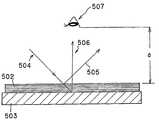
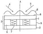
또한, 홀로그램 광학 소자의 화상 표시 장치용 반사판으로서의 응용예로서는 예를 들면, 일본 특개평9-138396호 공보에 기재되어 있는 바와 같이, 도 6에 도시하는 바와 같이, 외계로부터 직시용 반사형 액정 패널(502)에 입사하는 광선(504)을 홀로그램 반사판(503)에 의해 정반사 방향과는 다른 방향(506)으로 반사시킴으로써, 관찰자의 눈동자(507)에 직시용 반사형 액정 패널(502)의 표면 반사광(505)이 입사되는 것을 방지하여, 콘트라스트가 양호한 화상 표시를 하고자 하는 것이다. 또한, 이 경우의 홀로그램은 편광성 홀로그램일 필요는 없다.In addition, as an example of application of a holographic optical element as a reflecting plate for an image display device, as shown in Japanese Patent Application Laid-open No. Hei 9-138396, for example, as shown in FIG. By reflecting the
〔6-3〕투사형 화상 표시 장치용 편광 변환기[6-3] Polarization converters for projection image display devices
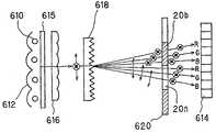
홀로그램 광학 소자의 투사형 화상 표시 장치용 편광 변환기로의 응용예에 있어서는 예를 들면, 일본 특개평8-234143호 공보에 기재되어 있는 바와 같이, 도 7에 도시하는 바와 같이, 광원(610)으로부터 방사되는 조명광은 알루미늄 증착 등이 실시된 반사판(612)에 의해 일방향으로 대략 평행 광속으로서 사출된다. 그리고, 조명광은 디퓨저(615)를 통과하여 확산된 후, 렌티큘러 어레이(616)에 입사된다. 이것은 LCD(액정 디스플레이; 614)로 조사되는 조명광의 휘도 얼룩을 저감하고, 또한 렌티큘러 어레이(616)의 직사각형 변환 기능 등에 의해, 조명 효율을 높이기 위해서이다.In the application example of the hologram optical element to the polarization converter for a projection type image display device, for example, as described in Japanese Patent Application Laid-open No. Hei 8-234143, as shown in FIG. 7, radiation from the
그리고, 조명광은 투과형 편광 선택성 홀로그램 광학 소자(618)에 입사한다. 여기서, 상술한 바와 같은 편광 선택성 홀로그램 광학 소자(618)의 기능에 의해, P편광, S 편광의 각 성분을 사출 각도에 의해 분리한다. 다음에, 조명광은 패턴화된 1/2 파장판 어레이(620)에 입사한다. 조명광은 이 1/2 파장판 어레이(620)에 있어서, P 편광 성분, S 편광 성분 중, LCD(614)의 입사 편광 방향에 대하여 직교하는 편광 방향 성분이 이 1/2 파장판 어레이(620)의 패턴화된 1/2 파장판 부분을 통과하여, 편광 방향을 90°변환한다.And, the illumination light is incident on the transmission polarization selective hologram
이 홀로그램 광학 소자는 이렇게 하여, 광원(610)으로부터 방사되는 조명광의 이용 효율을 향상시키도록 하는 것이다.This holographic optical element is intended to improve the utilization efficiency of the illumination light emitted from the
상술한 바와 같은 화상 표시 소자 및 화상 표시 장치에 관해서, 본 발명이 해결하고자 하는 과제를 이하에 나타낸다.Regarding the image display element and the image display device as described above, the problem to be solved by the present invention is shown below.
(1) 우선, 도 2에 도시한 반사형 공간 광변조 소자를 사용한 투사형의 화상 표시 장치처럼, 반사형 공간 광변조 소자를 조명하기 위해서 편광 빔 스플리터(이하 「PBS」라고 한다)를 사용한 경우에는 이 PBS는 적어도 반사형 공간 광변조 소자의 화상 표시부의 장변보다도 큰 길이의 변을 갖는 입방체 형상이 되기 때문에, 반사형 공간 광변조 소자와 투사 광학계와의 거리, 즉 투사 광학계의 백 포커스를 짧게 할 수 없다. 투사 광학계는 백 포커스가 길어지면, F 넘버를 작게 하는 것, 즉 밝은 렌즈로 하는 것이 곤란하게 된다. 따라서, 이 화상 표시 장치에 있어서는 광원으로부터 발생하는 조명광의 이용 효율이 낮다.(1) First, in the case of using a polarizing beam splitter (hereinafter referred to as "PBS") to illuminate the reflective spatial light modulator, as in the projection type image display apparatus using the reflective spatial light modulator shown in FIG. Since the PBS has a cubic shape having a side of a length larger than at least the long side of the image display portion of the reflective spatial light modulator, the distance between the reflective spatial light modulator and the projection optical system, that is, the back focus of the projection optical system can be shortened. Can't. If the projection optical system has a long back focus, it becomes difficult to reduce the F number, that is, to make a bright lens. Therefore, the utilization efficiency of the illumination light which arises from a light source in this image display apparatus is low.
또한, 이 화상 표시 장치에 있어서는 PBS를 사용함으로써, 장치 구성의 소형화가 곤란하고, 또한 이 PBS가 글래스제이기 때문에, 장치의 경량화가 곤란하다. 더욱이, 이 PBS는 복굴절 및 열 왜곡이 적은 양질의 글래스제로 제작하지 않으면 안되고, 또한 P 편광과 S 편광의 분리를 위해 유전체 다층막을 사용하고 있기 때문에, 고가의 부품이며, 화상 표시 장치 전체의 제조 비용의 저렴화를 곤란하게 하고 있다. 또한, 이 PBS는 편광 분리 특성의 입사 파장 의존성 및 입사 각도 의존성이 크기 때문에, 이 PBS를 사용하여 구성된 화상 표시 장치에 있어서는 고콘트라스트, 고균일성, 고색재현성을 갖는 화상의 표시를 하는 것이 곤란하다.Moreover, in this image display apparatus, by using PBS, it is difficult to miniaturize the apparatus structure and since this PBS is made of glass, it is difficult to reduce the weight of the apparatus. Furthermore, this PBS must be made of high quality glass with low birefringence and thermal distortion, and since it uses a dielectric multilayer film for separation of P polarized light and S polarized light, it is an expensive component and manufacture cost of the whole image display apparatus. It is difficult to reduce the cost. In addition, since this PBS has a large incidence wavelength dependency and incidence angle dependency of polarization separation characteristics, it is difficult to display an image having high contrast, high uniformity and high color reproducibility in an image display device constructed using this PBS. .
(2) 상술한 과제를 해결하는 하나의 수단으로서는 도 3에 도시한 바와 같은 PBS를 사용하지 않는 반사형 공간 광변조 소자용 조명 장치가 제안되어 있다. 그렇지만, 이 도 3에 도시하는 화상 표시 장치에 있어서는 이하에 나타내는 바와 같은 문제가 있다. 즉, 반사형 공간 광변조 소자의 윈도우면(입사 출사면)측에 설치된 홀로그램 광학 소자(303)가 편광 선택성 홀로그램 광학 소자가 아닌, 편광 의존성 홀로그램 소자이기 때문에, 광이용 효율이 낮다.(2) As one means for solving the above-mentioned problems, a lighting apparatus for a reflective spatial light modulator that does not use PBS as shown in FIG. 3 is proposed. However, there is a problem as described below in the image display device shown in FIG. That is, since the hologram
이것은 이 홀로그램 광학 소자가 굴절율 변동의 주기 구조를 구성하는 층에 복굴절성을 갖는 층을 갖고 있지 않기 때문에, P 편광, S 편광 중 어느 한쪽의 회절 효율을 0으로 하는 것이 불가능한 것에 의한다.This is because the hologram optical element does not have a layer having birefringence in the layer constituting the periodic structure of the refractive index variation, and therefore it is impossible to set the diffraction efficiency of either P polarization or S polarization to zero.
또한, 이 화상 표시 장치에 있어서는 화상 표시를 위한 조명광으로서 사용되어야 할 P 편광의 회절 효율을 가능하면 낮게 억제하고, 회절에 의해서 재차 조명 광원의 방향으로 되돌아가지 않도록 하기 위해서, 홀로그램 광학 소자에 의해 회절되는 S 편광 조명광을 반사형 공간 광변조 소자에 대하여 수직 방향으로부터 경사를 갖고 입사되며, P 편광으로 변환된 반사광의 홀로그램 광학 소자로의 재입사 각도를 1회째의 입사 각도와 다른 입사 각도로 함으로써, 회절 조건에 합치하지 않는 상태로 하는 수법이 제안되어 있다.In addition, in this image display device, diffraction is performed by the hologram optical element in order to suppress the diffraction efficiency of P polarization to be used as illumination light for image display as low as possible and not to return to the direction of the illumination light source again by diffraction. By making the S-polarized illumination light to be inclined from the perpendicular direction with respect to the reflective spatial light modulator, the re-incidence angle of the reflected light converted into the P-polarized light into the hologram optical element is an incident angle different from the first incident angle, The method which makes it a state which does not match a diffraction condition is proposed.
그런데, 이 경우, 반사형 공간 광변조 소자로부터의 반사광이 수직방향에 대하여 기울게 사출되어 텔레센터릭성이 무너지기 때문에, 통상의 공축 투사광학계에서는 효율 저하를 방지하기 위해서, 광학계의 이미지 사이클을 크게 할 필요가 생긴다. 투사광학계의 이미지 사이클을 크게 하면, 장치의 대형화, 고비용화를 초래하게 된다. 또한, 통상의 반사형 공간 광변조 소자에 있어서는 광선 입사 각도가 수직 방향으로부터 어긋나면, 콘트라스트가 열화되는 경우가 많기 때문에, 이 화상 표시 장치에 있어서는 고콘트라스트의 화상 표시를 행할 수 없게 된다.In this case, however, the reflected light from the reflective spatial light modulator is inclined with respect to the vertical direction and the telecentricity is collapsed. Therefore, in the conventional coaxial projection optical system, the image cycle of the optical system is increased in order to prevent the efficiency deterioration. There is a need. Increasing the image cycle of the projection optical system leads to an increase in the size and cost of the device. In addition, in the normal reflective spatial light modulator, when the light incident angle shifts from the vertical direction, the contrast is often deteriorated. Therefore, high contrast image display cannot be performed in this image display apparatus.
그리고, 이들의 문제 이전에, 이 화상 표시 장치에 있어서는 P 편광 성분을 회절 조건에 합치하지 않는 상태로 하는 것은 대단히 곤란하다는 문제가 있다. 즉, 이 화상 표시 장치에 있어서는 홀로그램 컬러 필터의 홀로그램 렌즈 중심과, 반사형 공간 광변조 소자의 화소 전극의 중심을 홀로그램 렌즈의 크기의 0.5 정도 물려 놓도록 되어 있다. 이 경우, 각 홀로그램 렌즈의 주광선의 반사형 공간 광변조 소자의 화소 전극으로의 입사각(θin)은And before these problems, in this image display apparatus, there exists a problem that it is very difficult to make P polarization component into a state which does not match a diffraction condition. That is, in this image display device, the center of the hologram lens of the hologram color filter and the center of the pixel electrode of the reflective spatial light modulator are about 0.5 of the size of the hologram lens. In this case, the incident angle [theta] in of the reflective spatial light modulator of the principal ray of each hologram lens to the pixel electrode is
θin= ArcTan〔r/Lp〕θin = ArcTan [r / Lp]
(∵r: 홀로그램 렌즈의 반경)(R: radius of hologram lens)
(∵Lp: 홀로그램 렌즈와 반사형 공간 광변조 소자의 알루미늄 화소 전극 사이의 두께 방향의 거리)(Lp: distance in thickness direction between the hologram lens and the aluminum pixel electrode of the reflective spatial light modulator)
이고, 지금 Lp= 0.7mm(커버 글래스 두께를 0.7mm라고 가정), r= 10㎛(R, G, B를 합친 1화소의 사이즈를 20㎛라고 가정)으로 하면 , θin은If Lp = 0.7 mm (assuming cover glass thickness is 0.7 mm) and r = 10 m (assuming the size of one pixel combined with R, G and B is 20 m), θin is
θin= ArcTan〔r/Lp〕= O.82°θin = ArcTan [r / Lp] = 0.82 °
로 된다. 이것은 홀로그램 컬러필터에 입사하는 조명광의 확장각(±10° 정도)에 비교하여 얼마 안되고, P 편광과 S 편광의 각도차가 1.64°(= 0.82×2)로 작은 경우, 이들을 입사각도에 의해 분리하는 것은 대단히 곤란하다.It becomes This is very small compared to the expansion angle (± 10 °) of the illumination light incident on the hologram color filter, and when the angle difference between P polarized light and S polarized light is small as 1.64 ° (= 0.82 × 2), these are separated by the incident angle. Is very difficult.
가령, 홀로그램 컬러필터의 회절 허용 각도의 범위가 1° 내지 2°라고 하면, 편광 분리 특성은 향상되지만, 조명광의 확대 각 ±10°중 실제로 회절되어 유효하게 사용할 수 있는 광량은 대단히 적어져 현실적이지 않다.For example, if the diffraction allowable angle of the hologram color filter is in the range of 1 ° to 2 °, the polarization separation characteristics are improved, but the amount of light that can be effectively diffracted and effectively used out of the enlargement angle of the illumination light ± 10 ° is very practical. not.
또한, 홀로그램 광학 소자의 편광 의존성을 이용하기 위해서는 S 편광이 입사광(즉, 회절광)으로 되도록 설정할 필요가 있기 때문에, 조명광의 이용 효율의 저하 및 표시 화상의 콘트라스트의 저하를 초래한다. 그리고, 이들 조명광의 이용 효율의 저하나 표시 화상의 콘트라스트의 저하를 억제하기 위해서는 그것을 위한 추가의 부재나 광학 소자가 필요해져, 장치 전체의 제조 비용이 증가하고, 중량 증가를 초래한다.In addition, in order to take advantage of the polarization dependency of the holographic optical element, it is necessary to set the S polarization to be incident light (that is, diffracted light), resulting in a decrease in utilization efficiency of illumination light and a decrease in contrast of a display image. And in order to suppress the fall of the utilization efficiency of these illumination light, and the fall of the contrast of a display image, the further member and optical element for it are needed, and the manufacturing cost of the whole apparatus increases and weight increases.
이것은 이하의 이유에 의한다. 즉, 도 8에 도시하는 바와 같이, 홀로그램 의 두께를 O에서 점차로 두껍게 해가는 과정에서 충분한 편광 의존성이 얻어지는 최초의 상태에 있어서는 S 편광에 대한 회절 효율이 대(大)로 되고, P 편광에 대한 회절 효율은 소(小)로 되어 있다. 그 후, 홀로그램의 두께(d)를 크게 해 감으로써, 반대로, P 편광에 대한 회절 효율이 크게되고, S 편광에 대한 회절 효율을 작게 하는 것도 가능하다.This is based on the following reasons. That is, as shown in Fig. 8, in the first state in which sufficient polarization dependency is obtained in the process of gradually increasing the thickness of the hologram at O, the diffraction efficiency for S polarization becomes large, and The diffraction efficiency is small. Thereafter, by increasing the thickness d of the hologram, on the contrary, the diffraction efficiency for P-polarized light can be increased, and the diffraction efficiency for S-polarized light can be reduced.
그러나, 투과형 홀로그램의 회절 효율의 파장 의존성, 입사 각도 의존성은 홀로그램의 두께가 늘어나는 동시에 비싸진다. 결국, 홀로그램 노광 시의 레이저의 소정의 파장, 소정의 입사각으로부터의 어긋남의 허용량(회절 효율을 확보할 수 있는 범위)이 작아져 버려, 광 이용 효율이 저하되는 문제가 있다.However, the wavelength dependence and the incident angle dependence of the diffraction efficiency of the transmission hologram become expensive at the same time as the thickness of the hologram increases. As a result, there is a problem that the allowable amount of the deviation (the range in which the diffraction efficiency can be secured) from the predetermined wavelength and the predetermined angle of incidence of the laser at the time of hologram exposure becomes small, resulting in a decrease in light utilization efficiency.
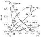
도 9 및 도 10은 물체 광 입사각 0°, 참조광 입사각 60°, 홀로그램의 평균 굴절율 1.52, 홀로그램층의 굴절율 변조도 0.05, 홀로그램층의 두께 5㎛, 노광 파장 532nm의 조건으로 제작된 홀로그램 광학 소자를 재생 파장 532nm에서 판독한 경우의 회절 효율의 입사 각도 의존성을 나타낸 것이다. 두께 6㎛인 것(도 9)과, 두께 18㎛인 것(도 10)에 대하여 계산한 결과이다. 또한, 여기서는 입사편광은 S 편광을 가정하고 있다. 이상으로부터, 실질적으로, 입사편광은 S 편광으로 할 필요가 있음을 알 수 있다.9 and 10 illustrate a hologram optical device manufactured under the conditions of an object light incident angle of 0 °, a reference light incident angle of 60 °, an average refractive index of hologram 1.52, a refractive index modulation degree of 0.05 hologram layer, a thickness of 5 μm of hologram layer, and an exposure wavelength of 532 nm. The incident angle dependence of the diffraction efficiency in the case of reading at the reproduction wavelength 532nm is shown. It is the result calculated about what is thickness of 6 micrometers (FIG. 9), and what is thickness 18 micrometers (FIG. 10). Incidentally, the incident polarization assumes S polarization. From the above, it is understood that the incident polarization needs to be S polarized light.
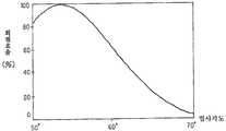
그런데, 굴절율이 작은 매체로부터 굴절율이 큰 매체로 광이 진행하는 경우, 그 표면 반사율에는 도 11에 도시하는 바와 같이, 편광 의존성이 있다. 이러한 편광 의존성에 의해, 공기 중에서 굴절율이 1.5인 글래스에, P 편광 및 S 편광이 입사한 경우의 표면 반사율은 항상 S 편광쪽이 크다. 또한, 입사각이 tanθ=n(=1.5)를 만족하는 각도 즉, 편광각(이 경우는 56.3°)일 때에는, P 편광의 반사율은 0으로 된다. 이 때, S 편광의 반사율은 15% 정도로 된다.By the way, when light advances from a medium with a small refractive index to a medium with a large refractive index, the surface reflectance has polarization dependency, as shown in FIG. By such polarization dependence, the surface reflectance when P polarization and S polarization enters the glass which has a refractive index of 1.5 in air is always larger in S polarization. In addition, when the incident angle satisfies tanθ = n (= 1.5), that is, the polarization angle (56.3 ° in this case), the reflectance of the P polarized light becomes zero. At this time, the reflectance of S polarized light is about 15%.
이것은 홀로그램 광학 소자의 글래스 기판에, 경사진 방향으로부터 광선을 입사(off-axis 입사)시키는 경우, P 편광을 입사하는 쪽이 광의 이용 효율이 좋은 것을 의미한다. 상술한 홀로그램 광학 소자에서는 S 편광을 입사시키지 않으면 안되기 때문에, 도 3에 도시하는 바와 같이, 커플링 프리즘(305)을 사용함으로써 효 율의 저하를 회피하고 있다. 그러나, 이러한 커플링 프리즘을 사용하는 것은 부품 점수의 증가, 장치의 중량 증가, 고비용화를 초래한다. 또한, 커플링 프리즘을 사용하더라도, 표면 반사율을 O으로 할 수는 없다. 따라서, 미광(迷光)의 발생이나, 표시 화상의 콘트라스트의 열화를 확실하게 방지할 수는 없다.This means that, when the light beam is incident on the glass substrate of the holographic optical element from the inclined direction (off-axis incidence), the light utilization efficiency is better for incidence of P polarization. Since the S-polarized light must be incident on the above-described holographic optical element, as shown in FIG. 3, the reduction of the efficiency is avoided by using the
더욱이, 커플링 프리즘을 사용하면, 조명수단으로부터 홀로그램층으로의 광선의 입사 화각은 조명 수단으로부터 사출되는 광선 화각 그 자체로 된다. 조명수단으로부터 사출되는 광선 화각은 전형적인 프로젝트 광학계의 경우에는 ±10°정도로 되고, 이 범위 내에서 홀로그램 광학 소자의 회절 효율을 높은 값으로 균일하게 유지하는 것은 용이하지 않다.Moreover, using the coupling prism, the incident angle of view of the light beam from the luminaire to the hologram layer is the light angle of view emitted from the luminaire itself. The light angle of view emitted from the luminaire is about 10 ° in the case of a typical project optical system, and it is not easy to uniformly maintain the diffraction efficiency of the hologram optical element at a high value within this range.
또한, 다음 식에 나타내는 라그랑쥬 헬름홀쯔(Lagrangian Helmholtz)의 불변량으로써 나타나는 바와 같이, 램프 광원으로부터의 조명광을 일정 면적의 화상 표시 장치에 조사하려고 집광하면, 그 입사각도(u′)는 화상 표시 소자의 크기(y′)에 반비례하여 작아진다.In addition, as shown by the invariant of Lagrangian Helmholtz shown in the following formula, when the illumination light from the lamp light source is condensed to irradiate the image display device of a predetermined area, the incident angle u 'is the image display element. It becomes small in inverse proportion to the size y 'of.
ynu= y′n′u′(라그랑쥬 헬름홀쯔의 불변량)ynu = y'n'u '(invariant of Lagrange Helmholtz)
(∵y: 광축으로부터의 상 높이)(Y: image height from the optical axis)
(∵n: 매질의 굴절율) (∵n': 화상표시소자의 매체의 굴절율)('N: refractive index of the medium) (' n ': refractive index of the medium of the image display element)
(∵u: 광선의 경사각)(U: angle of inclination of the ray)
상기 식은 곱(ynu)인 값이 광학계의 어떤 면에서도, 불변인 것을 나타내고 있다. 즉, 좌변의 곱(ynu)이 유한인 값을 잡는 한, 화상 표시 소자를 소형화하면, 화상 표시 소자로의 입사각은 더 커져 버린다. 이것은 고효율의 홀로그램 광학 소자를 실현하는 데에 있어서 한층 더 불리한 요인으로 된다. 도 9에 도시한 바와 같이, 회절 효율은 그 피크값을 부여하는 입사 각도로부터 +10°어긋나면 25%로, -10°어긋나면 거의 0%로 저하되는 것을 알 수 있다.The above equation indicates that the value ynu is invariant in any aspect of the optical system. In other words, as long as the product of the left side ynu is finite, when the image display element is downsized, the incident angle to the image display element becomes larger. This becomes a further disadvantageous factor in realizing a high efficiency holographic optical element. As shown in FIG. 9, it turns out that diffraction efficiency falls to 25% when it shifts by +10 degree from the incidence angle which gives the peak value, and to about 0% when it shifts by -10 degree.
또한, 상술한 화상 표시 장치에 있어서는 홀로그램 광학 소자를 항상 컬러필터로서 사용하고 있다. 그 때문에, 이 화상 표시 장치에 있어서는 홀로그램 광학 소자에 대략 화소의 면적과 같은 크기의 미소 렌즈를 작성하여, 이들 미소렌즈를 액정 표시 소자의 각 화소에 대하여 정확하게 위치 맞춤을 하는 공정이 필요하여, 제조의 곤란성 및 비용 증가가 초래된다.In the above-described image display device, holographic optical elements are always used as color filters. Therefore, in this image display device, a process is necessary in which a microlens having a size approximately equal to the area of a pixel is created in the holographic optical element, and the microlenses are accurately positioned with respect to each pixel of the liquid crystal display element. Difficulty and cost increase.
또한, 상술한 화상 표시 장치에 있어서는 소위 「필드 시퀀셜 컬러 수법」및 색광별로 반사형 화상 표시 소자를 복수 사용하는 장치 구성에 대응할 수 없다.In addition, in the above-described image display device, it is not possible to cope with a so-called "field sequential color method" and an apparatus configuration using a plurality of reflective image display elements for each color light.
또한, 상술한 홀로그램 컬러 필터를 사용한 화상 표시 장치에 있어서는 입사광에 대하여 각 색광마다 분광 및 집광을 하지 않아서는 안되기 때문에, 표시 화상의 색재현성이나 고정밀화와, 조명광의 이용 효율은 트레이드 오프(trade-off)의 관계로 된다.In addition, in the image display apparatus using the hologram color filter described above, spectroscopic and condensing should not be performed for each color light with respect to the incident light, so that the color reproducibility and high definition of the display image and the utilization efficiency of the illumination light are traded off. off) relationship.
이 관계에 대하여 이하에 설명한다. 도 12에 도시하는 바와 같이, 홀로그램 필터(700)와 반사형 공간 광변조 소자(701)의 화소 전극(702)의 사이의 거리를 Lp로 하고, 1색 화소 전극의 사이즈를 2r로 하고, 상기 1개의 색 화소 상에 조명광이 수속하기 위한 홀로그램 렌즈로부터의 주광선의 사출각 허용치(Δθi)를 구해 본다.This relationship will be described below. As shown in FIG. 12, the distance between the
Δθi= ArcTan〔r/Lp〕Δθi = ArcTan [r / Lp]
Lp= 0.7mm, r=±5㎛로 하면, Δθi=±0.4°로 된다.When Lp = 0.7mm and r = ± 5 μm, Δθ i = ± 0.4 °.
여기서, 홀로그램의 간섭 줄무늬에 의한 입사각(θc)과 회절 사출각(θi)은 다음에 나타내는 등식으로 관계지을 수 있다.Here, the incident angle [theta] c and the diffraction exit angle [theta] i due to the interference fringes of the hologram can be related by the following equation.
(Sin{θs}-Sin{θr})/λ=(Sin{θi〕-Sin{θc})/λc(Sin {θs} -Sin {θr}) / λ = (Sin {θi] -Sin {θc}) / λc
(∵θs: 홀로그램 제조 시의 물체광 입사각)(∵θs: object light incident angle at the time of hologram production)
(∵θr: 홀로그램 제조 시의 참조광 입사각)(∵θr: reference light incident angle at the time of hologram manufacturing)
(∵λ: 홀로그램 제조 파장)(∵λ: hologram wavelength)
(∵λc: 재생 파장)(∵λc: reproduction wavelength)
이것으로부터, 지금 θs=0 °, θr=60°, λ= 550nm, λc= 550nm, θi=±0.4°로 하면, θc= 60±0.8°로 되고, 조명광속의 홀로그램 컬러 필터로의 입사각도 허용 범위는 대단히 좁은 것을 알 수 있다. 또한, θs= 0°, θr= 60°, λ= 550nm, θc= 60°, θi=±0.4°로 하면, θc=550±4.5nm로 되고, 조명광의 홀로그램 컬러 필터로의 입사 파장 허용 범위는 대단히 좁은 것을 알 수 있다.From this, if θs = 0 °, θr = 60 °, λ = 550nm, λc = 550nm, θi = ± 0.4 °, the angle of incidence of the illumination light beam into the hologram color filter is allowed. It can be seen that the range is very narrow. Further, when θ s = 0 °, θ r = 60 °, λ = 550 nm, θ c = 60 ° and θ i = ± 0.4 °, θ c = 550 ± 4.5 nm, and the incident wavelength allowance range of the illumination light into the hologram color filter is You can see that it is very narrow.
이상의 사실로부터, 홀로그램 필터에 입사되는 조명광은 높은 평행도와 좁은 파장대역이 요구되고, 통상의 램프 광원을 사용하는 경우에는 발광부가 유한(1mm 정도)의 크기를 갖는 것 및 발광 파장 대역이 넓은 것의 2점으로부터, 광이용 효율이 현저하게 저하된다. 반대로, 광이용 효율을 향상시키고자 하면, 화소 사이즈를 크게 하거나, 인접하는 색 화소로의 누설광을 허용하는 수단밖에 없고, 전자에 있어서는 표시 화상의 정밀도, 후자에 대해서는 색 순도, 색재현성이 각각 저하된다.In view of the above, the illumination light incident on the hologram filter requires a high parallelism and a narrow wavelength band, and in the case of using a conventional lamp light source, the light emitting portion has a finite size (about 1 mm) and the light emission wavelength band is wide. From this point, the light utilization efficiency is significantly reduced. Conversely, in order to improve the light utilization efficiency, there are only means for increasing the pixel size or allowing leakage light to adjacent color pixels. In the former, the precision of the display image and the color purity and color reproducibility for the latter are respectively. Degrades.
그리고, 상술한 화상 표시 장치에 있어서는 홀로그램 광학 소자를 반사형으 로서 사용할 수 없다. 이것은 도 4에 도시하는 바와 같이, 홀로그램 광학 소자를 반사형으로 사용하여, P 편광과 S 편광에서 회절 효율의 차가, 예를 들면, 30% 이상으로 되도록 하기 위해서는 d/∧(d: 홀로그램의 두께, ∧: 간섭 줄무늬의 피치)가 1.0 내지 3.0 정도의 값으로 될 필요가 있다(참고 문헌 M.G. Mohararm and T. K. Gayload: Rigourous coupled-wave analysis of planar grating diffraction, J.ODt. Soc. Am. 71, 811-818(1977)로부터의 인용).And in the above-mentioned image display apparatus, a hologram optical element cannot be used as a reflection type. As shown in Fig. 4, this is achieved by using a hologram optical element as a reflection type so that the difference in diffraction efficiency between P polarized light and S polarized light becomes 30% or more, for example, d / ∧ (d: thickness of hologram). , ∧: pitch of interference fringes) needs to be in the range of 1.0 to 3.0 (Ref. MG Mohararm and TK Gayload: Rigourous coupled-wave analysis of planar grating diffraction, J.ODt. Soc. Am. 71, 811 -818 (1977).
여기서, ∧=λ/|2Sin〔(θs-θr)/2〕|Where ∧ = λ / | 2Sin [(θs-θr) / 2] |
(∵θs: 물체광의 입사각)(∵θs: incident angle of the object light)
(∵θr: 참조광의 입사각)(∵θr: incident angle of the reference light)
이므로, P 편광, S 편광 중 어느 한쪽이 수직 입사인 경우, 반사형 홀로그램으로 되기 위해서는 (θs-θr)의 최소치는 90°로 된다. 이 때,Therefore, in the case where either P-polarized light or S-polarized light is vertical incidence, the minimum value of (θs-θr) is 90 ° in order to be a reflective hologram. At this time,
|2Sin〔(θs-θr)/2〕|2Sin ((θs-θr) / 2] |
는 최소치 1.41을 잡는다. λ=0.5㎛로 하면, 이 때 ∧는 최대치가 0.35㎛로 되고, d/∧=1.0 내지 3.0을 만족하는 홀로그램의 두께(d)는 최대라도 1㎛로 된다. 이 만큼 얇은 홀로그램층을 제작하는 것은 매우 곤란하다.Catches the minimum 1.41. If lambda = 0.5 占 퐉, then the maximum value of ∧ is 0.35 占 퐉, and the thickness d of the hologram that satisfies d / ∧ = 1.0 to 3.0 is 1 占 퐉 at the maximum. It is very difficult to produce such a thin hologram layer.
상술한 바와 같이 종래부터 제안되어 있는 여러 가지의 홀로그램 광학 소자의 응용 기술에 있어서, 조명광을 비스듬하게 입사함으로써 반사형 공간 광변조 소자를 고효율로 조명할 수 있는 응용 기술은 없었다.As described above, in the conventionally proposed application techniques of various holographic optical elements, there is no application technique capable of illuminating the reflective spatial light modulator with high efficiency by inclined illumination light.
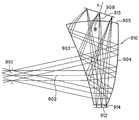
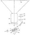
다음에, 반사형 공간 광변조 소자를 사용한 허상 표시 광학계에는 USP 5,596,451호에 공개되어 있는 바와 같이, 도 13에 도시하는 바와 같이, 입방체형의 편광 빔 스플리터(848)의 구성면 부근에 반사형 공간 광변조 소자(836), 조명 광원(834), 반사경(842)을 배치한 구성이 있다.Next, as disclosed in USP 5,596,451 in the virtual image display optical system using the reflective spatial light modulator, as shown in FIG. 13, the reflective spatial light is formed near the constituent surface of the cubic
그런데, 이 광학계에서는 도 13에 있어서 분명한 바와 같이, 조명광의 일부(860)가 편광 빔 스플리터(848)에 의해서, 반사형 공간 광변조 소자(836)에 도달하지 않고서, 직접 관찰자의 관찰 영역(846)에 도달하여 버리고, 이 조명광이 노이즈로서 관찰자의 눈동자(824)에 입사함으로써, 반사형 공간 광변조 소자(836)가 표시하는 화상 정보의 콘트라스트가 저하되는 본질적인 문제가 있다.In this optical system, however, as shown in FIG. 13, a part of the
또한, 이 광학계에서는 광학계 전체가 입방체형의 형상으로 되기 때문에, 두께가 커진다. 또한, 편광 빔 스플리터의 유전체막(864)의 성능을 높이면 제조 비용이 비싸지고, 반대로, 상기 유전체막의 성능이 낮으면, 유전체막의 편광 반사율이나 투과율의 입사 각도 의존성, 파장 의존성에 의해, 특히 눈동자의 이동에 따라 화상의 균일성이 저하되는 문제가 있다.Moreover, in this optical system, since the whole optical system becomes a cubic shape, thickness becomes large. In addition, if the performance of the
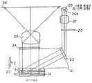
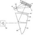
이것을 개선하기 위해서, 일본 특개평11-125791호 공보에 기재되어 있는 화상 표시 장치에 있어서는 도 14에 도시하는 바와 같이, 반사형 공간 광변조 소자(908) 및 자유 곡면 프리즘(910)을 사용하여 허상 표시 광학계를 구성하고 있다.In order to improve this, in the image display device described in Japanese Patent Laid-Open No. 11-125791, as shown in FIG. 14, a virtual image is formed using a reflective spatial
이 화상 표시 장치에 있어서는 도 14에 도시하는 바와 같이, 반사형 공간 광변조 소자(908)에 대하여, 광원(912)으로부터의 조명광을 직접 입사시키고, 반사광을 자유 곡면 프리즘(910)에 제 3 면(905)으로부터 입사시키고, 제 1 면(903)에서의 반사, 제 2 면(904)에서의 반사, 제 1 면(903)의 투과를 지나서, 눈동자(901)에 도달시켜서, 허상 표시를 행하고 있다. 이 광학계의 문제점으로서는 반사형 공간 광변조 소자(908)에 입사하는 조명광의 입사각이 커져 버려, 반사형 공간 광변조 소자(908) 자체의 변조도가 저하되고, 표시 화상의 콘트라스트가 열화되는 경우가 있다.In this image display device, as shown in FIG. 14, the illumination light from the
또한, 도 15에 도시하는 바와 같이, 자유 곡면 프리즘(910)내를 통과하여 광원(912)으로부터 방사되는 조명광을 반사형 공간 광변조 소자(908)에 입사시키고, 이 반사광을 자유 곡면 프리즘(910)에 제 3 면(905)으로부터 입사시키고, 제 1 면(903)에서의 반사, 제 2 면(904)에서의 반사, 제 1 면(903)의 투과를 지나서, 눈동자(901)에 도달시키고, 허상 표시를 하는 광학계의 경우에는 주로 2개의 문제가 있다.In addition, as shown in FIG. 15, the illumination light emitted from the
첫번째 문제는 반사형 공간 광변조 소자(908)가 편광 변조형(위상 변조형)의 공간 광변조 소자인 경우, 반사형 공간 광변조 소자(908)에 입사되는 조명광은 특정한 편광 방향을 갖는 직선편광이 아니어서는 안 된다. 그런데, 자유 곡면 프리즘(910)은 플라스틱 재료로 사출 성형으로 제조되기 때문에, 내부에 복굴절을 갖는다. 이 때문에, 직선 편광광을 자유 곡면 프리즘(910)에 입사되더라도 편광 상태가 보존되지 않고, 표시 화상의 콘트라스트가 열화되는 문제가 생긴다. 이것은 편광판을 반사형 공간 광변조 소자(908)와 자유 곡면 프리즘(910)의 제 3 면(굴절면; 905)의 사이에 배치함으로써, 외관상으로 회피할 수 있지만, 이 때, 표시 모드가 「노멀리화이트」가 되어, 역시 표시 화상의 콘트라스트가 열화되는 요인으로 된다.The first problem is that when the reflective spatial
두번째 문제는 조명광이 접안 광학계인 자유 곡면 프리즘(910)에 입사되는 것에 동반하는 것으로, 상기 조명광이 자유 곡면 프리즘(910) 내부에서, 각 광학면(903, 904, 905)에서 내부 반사를 일으켜, 미광을 발생시키는 것이다. 이 미광의 일부는 관찰자의 눈동자(901)에 도달하기 때문에, 역시 표시 화상의 콘트라스트의 열화의 요인으로 된다.The second problem is accompanied by the incidence of illumination light into the free-
이와 같이, 종래부터 제안되어 있는 여러 가지 화상 표시 장치에 있어서는 하프 미러를 사용한 조명 광학계에서는 장치의 소형화가 곤란하고, 또한 조명광의 이용 효율이 낮으며, 편광 빔 스플리터를 사용한 조명 광학계에서는 장치의 소형화가 곤란하며 또한, 표시 화상의 균일성이 낮고, 제조 비용이 비싸며, 공간 광변조 소자를 직접 조명하는 조명 광학계 및 플라스틱제 광학 부재를 통하여 조명하는 조명 광학계에서는 표시 화상의 콘트라스트를 저하시키는 문제가 있다.As described above, in the various conventionally proposed image display apparatuses, miniaturization of the apparatus is difficult in the illumination optical system using the half mirror, and the utilization efficiency of the illumination light is low, and miniaturization of the apparatus in the illumination optical system using the polarizing beam splitter is difficult. In addition, it is difficult, and the uniformity of a display image is low, manufacturing cost is high, and the illumination optical system which illuminates a spatial light modulation element directly, and the illumination optical system which illuminates through a plastic optical member has a problem of reducing the contrast of a display image.
그래서, 본 발명은 상술한 실정을 감안하여 제안되는 것으로서, 조명광의 광이용 효율이 높고, 장치의 소형화, 저비용화가 가능하고, 또한 표시 화상의 균일성, 고콘트라스트성이 실현된 화상 표시 소자 및 화상 표시 장치를 제공하고자 하는 것이다.Therefore, the present invention has been proposed in view of the above-described circumstances, and is an image display element and an image in which the light utilization efficiency of illumination light is high, the device can be miniaturized and the cost can be reduced, and the uniformity and high contrast of the display image are realized. It is to provide a display device.
상술한 과제를 해결하기 위해서, 본 발명에 따른 화상 표시 소자는 굴절율의 입사 편광 방위 의존성이 서로 다른 2개의 영역을 순차 적층한 구조를 갖고 조명광을 회절시키는 편광 선택성 홀로그램 광학 소자와, 편광 선택성 홀로그램 광학 소자에 의해 회절된 조명광의 편광 상태를 변조하는 반사형 공간 광변조 소자를 구비하고 있다.MEANS TO SOLVE THE PROBLEM In order to solve the above-mentioned subject, the image display element which concerns on this invention has the structure which laminated | stacked two area | regions from which the incident polarization orientation dependence of refractive index differs, and diffracts illumination light, and polarization selective hologram optics A reflective spatial light modulator for modulating the polarization state of illumination light diffracted by the device is provided.
그리고, 이 화상 표시 소자에 있어서는 편광 선택성 홀로그램 광학 소자가 2개의 영역 중 한쪽이 굴절율 이방성을 갖고, 다른 쪽이 굴절율 등방성을 갖는 것으로서, 조명광 수광면의 법선에 대하여 30°이상 90°미만의 입사각으로 조명광을 입사하고, 조명광의 P 편광 성분 또는 S 편광 성분을 회절시켜 반사형 공간 광변조 소자를 향하여 출사함과 동시에, 이 반사형 공간 광변조 소자에 의해 위상 변조되어 재입사하는 조명광 중, 1회째의 입사에 있어서 회절되는 편광 성분의 편광 방향과 직교하는 편광 방향인 편광 성분에 대한 회절 효율이 10% 이하임으로써, 이 편광 성분을 70% 이상 투과시키는 것을 특징으로 하는 것이다.In this image display element, the polarization selective hologram optical element has one of two regions having refractive index anisotropy and the other having refractive index isotropy, with an incident angle of 30 ° or more and less than 90 ° with respect to the normal of the illumination light receiving surface. The first of the illumination light incident on the illumination light, diffracted P polarization component or S polarization component of the illumination light and exits toward the reflective spatial light modulator, and is phase modulated and reincident by the reflective spatial light modulator; When the diffraction efficiency with respect to the polarization component which is a polarization direction orthogonal to the polarization direction orthogonal to the polarization direction diffracted at the incidence of 10% or less, it transmits 70% or more of this polarization component.
그리고, 본 발명에 따른 화상 표시 장치는 상술한 본 발명에 따른 화상 표시 소자와, 조명광을 방사하는 광원과, 이 광원으로부터 방사된 조명광을 화상 표시 소자의 편광 선택성 홀로그램 광학 소자에 입사되는 조명 광학계와, 화상 표시 소자의 반사형 공간 광변조 소자 및 편광 선택성 홀로그램 광학 소자를 거친 조명광을 스크린 상에 투사하는 투사 광학계를 구비하고 있다.The image display device according to the present invention includes an image display element according to the present invention described above, a light source for emitting illumination light, an illumination optical system in which illumination light emitted from the light source is incident on the polarization selective hologram optical element of the image display element, and And a projection optical system for projecting illumination light that has passed through the reflective spatial light modulator of the image display element and the polarization selective hologram optical element on the screen.
이 화상 표시 장치에 있어서는 편광 선택성 홀로그램 광학 소자는 2개의 영역중 한쪽이 굴절율 이방성을 갖고, 다른 쪽이 굴절율 등방성을 갖고, 조명 광학계에 의해, 조명광 수광면의 법선에 대하여 30°이상 90°미만의 입사각으로 조명광을 입사하고, 조명광의 P 편광 성분 또는 S 편광 성분을 회절시켜 반사형 공간 광변조 소자를 향하여 출사함과 동시에, 이 반사형 공간 광변조 소자에 의해 위상 변조되어 재입사하는 조명광 중, 1회째의 입사에 있어서 회절되는 편광 성분의 편광 방향과 직교하는 편광 방향인 편광 성분에 대한 회절 효율이 10% 이하임으로써, 이 편광 성분을 70% 이상 투과시켜, 투사광학계는 편광 선택성 홀로그램 광학 소자의 투과광을 스크린 상에 투사하는 것을 특징으로 하는 것이다.In this image display device, one of two regions has a refractive index anisotropy, and the other has a refractive index isotropy, and the illumination optical system has a polarization-selective holographic optical element of 30 ° or more and less than 90 ° with respect to the normal of the illumination light receiving surface. Among the illumination light incident on the illumination light at the incident angle, diffracting the P-polarized component or the S-polarized component of the illumination light and exiting it toward the reflective spatial light modulator, the phase-modulated and reincident by the reflective spatial light modulator, When the diffraction efficiency with respect to the polarization component that is the polarization direction orthogonal to the polarization direction of the polarization component diffracted at the first incidence is 10% or less, 70% or more of the polarization component is transmitted, and the projection optical system transmits the polarization selective hologram optical element. Projecting the transmitted light on the screen.
또한, 본 발명에 따른 화상 표시 장치는 상술한 화상 표시 장치에 있어서, 조명광을 서로 다른 복수의 파장 대역 성분으로 분리하는 색분리 수단을 설치하고, 조명 광학계를, 서로 다른 복수의 파장 대역 성분으로 분리된 조명광을 편광 선택성 홀로그램 광학 소자에 입사시키는 것으로 하고, 반사형 공간 광변조 소자를 복수로서, 편광 선택성 홀로그램 광학 소자에 의해 회절된 조명광 중 서로 다른 복수의 파장 대역 성분의 편광 상태를 각각 변조하는 것으로 하고, 복수의 반사형 공간 광변조 소자에 의해 각각 변조된 서로 다른 파장대역의 조명광을 합성하는 색합성 수단을 설치하고, 투사광학계를, 색합성 수단을 거친 조명광을 스크린 상에 투사하는 것으로 한 것이다. 그리고, 이 화상 표시 장치는 투사광학계가 편광 선택성 홀로그램 광학 소자를 투과하여 색합성 수단을 거친 조명광을 스크린 상에 투사하는 것을 특징으로 하는 것이다.Further, the image display device according to the present invention, in the image display device described above, is provided with color separation means for separating the illumination light into a plurality of different wavelength band components, and separates the illumination optical system into a plurality of different wavelength band components. The incident illumination light is incident on the polarization selective hologram optical element, and the reflective spatial light modulator is used as a plurality, and the polarization states of a plurality of different wavelength band components among the illumination light diffracted by the polarization selective hologram optical element are respectively modulated. And color synthesizing means for synthesizing illumination light of different wavelength bands respectively modulated by a plurality of reflective spatial light modulators, and projecting optical system to project illumination light through the color synthesizing means onto the screen. . The image display device is characterized in that the projection optical system transmits the illumination light passing through the color synthesizing means on the screen by passing through the polarization selective hologram optical element.
또한, 본 발명에 따른 화상 표시 장치는 상술한 화상 표시 장치에 있어서, 조명광의 서로 다른 제 1 및 제 2 파장 대역 성분의 편광 상태를 서로 직교하는 직선 편광 성분으로서 분리시키는 파장 대역별 편광 분리 수단을 설치하고, 조명 광학계를 제 1 및 제 2 파장 대역 성분으로 분리된 조명광을 편광 선택성 홀로그램 광학 소자에 입사하는 것으로 하고, 제 1 및 제 2 반사형 공간 광변조 소자를 설치하여 이들을 편광 선택성 홀로그램 광학 소자에 의해 회절된 조명광의 제 1 및 제 2 파장 대역 성분의 편광 상태를 대응하여 변조하는 것으로 하여, 투사광학계를 각 반사형 공간 광변조 소자를 거친 조명광을 스크린 상에 투사하는 것으로 한 것이다. 그리고, 이 화상 표시 장치는 투사광학계가 제 1 반사형 공간 광변조 소자 및 편광 선택성 홀로그램 광학 소자를 거친 제 1 파장 대역 성분의 조명광과, 제 2 반사형 공간 광변조 소자 및 편광 선택성 홀로그램 광학 소자를 거친 제 2 파장 대역 성분의 조명광을, 스크린 상에 투사하는 것을 특징으로 하는 것이다.Further, the image display device according to the present invention, in the above-described image display device, the polarization separation means for each wavelength band for separating the polarization state of the different first and second wavelength band components of the illumination light as a linear polarization component orthogonal to each other The illumination light separated by the first and second wavelength band components into the polarization selective hologram optical element, and the first and second reflective spatial light modulators are provided and the polarization selective hologram optical element is provided. The polarization states of the first and second wavelength band components of the illumination light diffracted by the corresponding modulation are correspondingly modulated, so that the projection optical system projects the illumination light passing through each reflective spatial light modulator on the screen. In addition, the image display apparatus includes a projection optical system in which illumination light of a first wavelength band component passed through a first reflective spatial light modulator and a polarization selective hologram optical element, and a second reflective spatial light modulator and a polarization selective hologram optical element. The illumination light of the rough second wavelength band component is projected on the screen.
그리고, 본 발명에 따른 화상 표시 장치는 상술한 화상 표시 장치에 있어서, 투사광학계 대신에, 반사형 공간 광변조 소자를 거친 조명광을 관찰자의 눈동자로 유도하는 허상 관찰 광학계를 설치하고, 이 허상 관찰 광학계는 편광 선택성 홀로그램 광학 소자의 투과광을 관찰자의 눈동자로 유도하는 것으로 한 것을 특징으로 하는 것이다.In the image display apparatus according to the present invention, in the image display apparatus described above, a virtual image observation optical system for guiding illumination light passing through the reflective spatial light modulation element to the observer's eyes instead of the projection optical system is provided. Is characterized in that the transmitted light of the polarization selective hologram optical element is guided to the observer's eyes.
도 1a 내지 도 1c는 종래의 화상 표시 소자(FLC)의 구성을 도시하는 단면도.1A to 1C are cross-sectional views showing the structure of a conventional image display element FLC.
도 2는 반사형 공간 광변조 소자에 대응한 편광 빔 스플리터를 사용한 종래의 화상 표시 장치의 구성을 도시하는 측면도.Fig. 2 is a side view showing the structure of a conventional image display apparatus using a polarizing beam splitter corresponding to a reflective spatial light modulator.
도 3은 홀로그램 렌즈를 사용한 종래의 화상 표시 장치의 구성을 도시하는 단면도.3 is a cross-sectional view showing the configuration of a conventional image display apparatus using a hologram lens.
도 4는 반사형 홀로그램의 회절 효율을 도시하는 그래프.4 is a graph showing the diffraction efficiency of the reflective hologram.
도 5a 및 도 5b는 광 스위치로서의 홀로그램 광학 소자의 응용예를 도시하는 단면도.5A and 5B are sectional views showing an application example of the hologram optical element as an optical switch.
도 6은 홀로그램 광학 소자의 화상 표시 장치용 반사판으로서의 응용예를 도시하는 단면도.6 is a cross-sectional view showing an application example of a holographic optical element as a reflecting plate for an image display device.
도 7은 홀로그램 광학 소자의 투사형 화상 표시 장치용 편광 변환기로의 응 용예를 도시하는 단면도.Fig. 7 is a sectional view showing an example of application of a hologram optical element to a polarization converter for a projection image display device.
도 8은 홀로그램의 두께와 회절 효율(Coupled-wave theory의 엄밀해에 의한 투과형 홀로그램의 회절 효율)과의 관계를 도시하는 그래프.Fig. 8 is a graph showing the relationship between the thickness of the hologram and the diffraction efficiency (the diffraction efficiency of the transmissive hologram due to the exactness of the coupled-wave theory).
도 9는 두께 6㎛의 홀로그램에 있어서의 회절 효율의 입사 각도 의존성을 도시하는 그래프.9 is a graph showing the incidence angle dependence of diffraction efficiency in a hologram having a thickness of 6 μm.
도 10은 두께 18㎛의 홀로그램에 있어서의 회절 효율의 입사 각도 의존성을 도시하는 그래프.10 is a graph showing the incidence angle dependency of diffraction efficiency in a hologram having a thickness of 18 μm.
도 11은 글래스의 표면 반사율(굴절율=1.5)과 입사 각도의 관계를 도시하는 그래프.FIG. 11 is a graph showing the relationship between the surface reflectance (refractive index = 1.5) and the incident angle of glass. FIG.
도 12는 종래의 홀로그램 컬러 필터에 있어서의 홀로그램 렌즈로부터의 주광선의 사출각 허용치를 도시하는 단면도.Fig. 12 is a cross-sectional view showing the exit angle tolerance of chief rays of light from a hologram lens in a conventional hologram color filter.
도 13은 편광 빔 스플리터를 사용한 종래의 화상 표시 장치의 구성을 도시하는 측면도.Fig. 13 is a side view showing the structure of a conventional image display apparatus using a polarizing beam splitter.
도 14는 허상 관찰 광학계를 사용한 종래의 화상 표시 장치의 구성을 도시하는 측면도.Fig. 14 is a side view showing the structure of a conventional image display apparatus using a virtual image observation optical system.
도 15는 허상 관찰 광학계를 사용한 종래의 화상 표시 장치의 구성의 다른 예를 도시하는 측면도.15 is a side view showing another example of the configuration of a conventional image display apparatus using a virtual image observation optical system.
도 16은 본 발명에 따른 화상 표시 소자의 구성을 도시하는 종단면도.16 is a longitudinal sectional view showing a configuration of an image display element according to the present invention;
도 17은 본 발명에 따른 화상 표시 소자의 제 1 실시예의 구성을 도시하는 종단면도.Fig. 17 is a longitudinal sectional view showing the arrangement of the first embodiment of the image display element according to the present invention;
도 18은 본 발명에 따른 화상 표시 소자의 제 2 실시예의 구성을 도시하는 종단면도.18 is a longitudinal sectional view showing a configuration of a second embodiment of an image display element according to the present invention;
도 19는 본 발명에 따른 화상 표시 소자의 제 3 실시예의 구성을 도시하는 종단면도.19 is a longitudinal sectional view showing a configuration of a third embodiment of an image display element according to the present invention.
도 20은 본 발명에 따른 화상 표시 소자의 제 4 실시예의 구성을 도시하는 측면도.20 is a side view showing the arrangement of a fourth embodiment of an image display element according to the present invention;
도 21은 본 발명에 따른 화상 표시 장치의 제 5 실시예의 구성을 도시하는 측면도.Fig. 21 is a side view showing the arrangement of the fifth embodiment of the image display device according to the present invention.
도 22는 상기 화상 표시 장치에 있어서의 보정용 편광 선택성 홀로그램 광학 소자에 의한 입사각의 보정의 원리를 도시하는 측면도.Fig. 22 is a side view showing the principle of correction of the incident angle by the polarization selective hologram optical element for correction in the image display device.
도 23은 상기 화상 표시 장치에 있어서의 재생 파장 450nm에서의 회절 효율의 입사 각도 의존성을 도시하는 그래프.FIG. 23 is a graph showing the incidence angle dependence of diffraction efficiency at a reproduction wavelength of 450 nm in the image display device. FIG.
도 24는 상기 화상 표시 장치에 있어서의 재생 파장 550nm에 있어서의 회절 효율의 입사 각도 의존성을 도시하는 그래프.Fig. 24 is a graph showing the incidence angle dependence of diffraction efficiency at a reproduction wavelength of 550 nm in the image display device.
도 25는 상기 화상 표시 장치에 있어서의 재생 파장 650nm에서의 회절 효율의 입사 각도 의존성을 도시하는 그래프.Fig. 25 is a graph showing the incidence angle dependency of diffraction efficiency at a reproduction wavelength of 650 nm in the image display device.
도 26a 및 도 26b는 휨각 대(大)(θob1=10°)인 경우의 회절 효율의 재생 파장 및 입사각 의존성을 도시하는 그래프.26A and 26B are graphs showing the reproducing wavelength and incidence angle dependence of diffraction efficiency when the bending angle is large (θob1 = 10 °).
도 27a 및 도 27b는 휨각 소(小)(θob1=-10°)인 경우의 회절 효율의 재생 파장 및 입사각 의존성을 도시하는 그래프.27A and 27B are graphs showing the reproduction wavelength and the incident angle dependence of diffraction efficiency when the bending angle is small (θob1 = −10 °).
도 28은 본 발명에 따른 화상 표시 장치의 제 6 실시예의 구성을 도시하는 측면도.Fig. 28 is a side view showing the arrangement of a sixth embodiment of an image display device according to the present invention;
도 29는 본 발명에 따른 화상 표시 장치의 제 7 실시예의 구성을 도시하는 측면도.Fig. 29 is a side view showing the arrangement of the seventh embodiment of the image display device according to the present invention.
도 30은 본 발명에 따른 화상 표시 장치의 제 8 실시예의 구성을 도시하는 측면도.30 is a side view showing the arrangement of an eighth embodiment of an image display device according to the present invention;
도 31은 본 발명에 따른 화상 표시 장치의 제 8 실시예의 구성을 도시하는 측면도.Fig. 31 is a side view showing the arrangement of the eighth embodiment of the image display device according to the present invention.
도 32는 본 발명에 따른 화상 표시 장치의 제 9 실시예의 구성을 도시하는 측면도.32 is a side view showing the construction of a ninth embodiment of an image display device according to the present invention;
도 33은 본 발명에 따른 화상 표시 장치의 제 10 실시예의 구성을 도시하는 측면도.33 is a side view showing the arrangement of a tenth embodiment of an image display device according to the present invention;
도 34는 본 발명에 따른 화상 표시 장치의 제 10 실시예의 구성을 도시하는 측면도.Fig. 34 is a side view showing the arrangement of the tenth embodiment of the image display device according to the present invention.
도 35는 본 발명에 따른 화상 표시 장치의 제 11 실시예의 구성을 도시하는 측면도.Fig. 35 is a side view showing the arrangement of the eleventh embodiment of image display device according to the present invention;
도 36은 본 발명에 따른 화상 표시 장치의 제 12 실시예의 구성을 도시하는 측면도.36 is a side view showing the arrangement of a twelfth embodiment of the image display device according to the present invention;
도 37은 본 발명에 따른 화상 표시 장치의 제 13 실시예의 구성을 도시하는 측면도.Fig. 37 is a side view showing the construction of the thirteenth embodiment of an image display device according to the present invention;
도 38은 본 발명에 따른 화상 표시 장치의 제 14 실시예의 구성을 도시하는 측면도.38 is a side view showing the construction of the fourteenth embodiment of an image display device according to the present invention;
도 39는 본 발명에 따른 화상 표시 장치의 제 15 실시예의 구성을 도시하는 측면도.Fig. 39 is a side view showing the arrangement of the fifteenth embodiment of the image display device according to the present invention;
이하, 본 발명의 실시예를 도면을 참조하여 설명한다.Hereinafter, embodiments of the present invention will be described with reference to the drawings.
〔1〕편광 선택성 홀로그램 광학 소자를 사용한 반사형 화상 표시 소자[1] reflective image display elements using polarization-selective holographic optical elements
본 발명에 따른 화상 표시 소자로서, 고분자 분산 액정(이하,「PDLC」라고 한다.)을 재료로 한 액정 패널을 편광 선택성 홀로그램 광학 소자로서 갖고 있는 실시예에 관해서 설명한다.As an image display element according to the present invention, an embodiment in which a liquid crystal panel made of a polymer dispersed liquid crystal (hereinafter referred to as "PDLC") as a material is used as a polarization selective hologram optical element.
처음에, 도 16에 도시하는 바와 같이,「PDLC」를 사용한 편광 선택성 홀로그램 광학 소자에 관해서, 구조 및 제조 프로세스에 관해서 설명한다. 또, 제조 프로세스 중은 소자의 온도를 60℃ 정도로 유지해 두는 것이 중요하다.First, as shown in FIG. 16, a structure and a manufacturing process are demonstrated about the polarization selective hologram optical element which used "PDLC." In addition, it is important to keep the temperature of the device at about 60 ° C during the manufacturing process.
우선, 광 중합을 일으키기 전의 고분자(이하, 프리폴리머라고 한다.), TN 액정, 개시제, 색소 등이 혼합된「PDLC」를 글래스 기판(1, 2) 사이에 끼운다. 이 때, TN 액정의 중량 비율은 전체의 30% 정도로 한다. 또한, 이「PDLC」의 층 두께(이하, 셀 갭이라고 한다.)는 2㎛ 내지 15㎛의 범위로, 편광 선택성 홀로그램 광학 소자의 사양에 맞추어서 최적치를 고른다.First, "PDLC" mixed with a polymer (hereinafter referred to as a prepolymer), a TN liquid crystal, an initiator, a dye and the like before photopolymerization is sandwiched between the
다음에,「PDLC」패널(3)에 간섭 줄무늬를 기록하기 위해서, 도시하지 않는 레이저 광원으로부터의 물체광(4) 및 참조광(5)을「PDLC」패널(3)에 조사하여, 간 섭에 의한 광의 강약 B를 발생시킨다. 이 때, 간섭 줄무늬가 밝은 곳, 즉, 광자의 에너지가 큰 장소에서는 그 에너지에 의해,「PDLC」중의 프리폴리머가 광 중합을 일으켜서 폴리머화한다. 이 때문에, 프리폴리머가 주변부로부터 잇달아 공급되고, 결과적으로 폴리머화한 프리폴리머가가 빽빽한 영역과 성긴 영역으로 분리된다. 프리폴리머가 성긴 영역에서는 TN 액정의 농도가 높아지고, 이렇게 해서, 고분자 영역(6)과 액정 영역(7)의 2개의 영역이 형성된다.Next, in order to record the interference fringes on the "PDLC"
본 실시예의 경우, 물체광(4)과 참조광(5)이「PDLC」패널(3)에 대하여 동일한 면측으로부터 조사되고 있기 때문에, 이로써 제조되는 편광 선택성 홀로그램 광학 소자는 투과형이 되지만, 물체광(4)과 참조광(5)을「PDLC」패널(3)에 대하여 서로 다른 면측으로부터 조사하면, 반사형의 편광 선택성 홀로그램 광학 소자를 제조할 수 있다.In the case of this embodiment, since the
그런데, 상술한 바와 같이 제조된「PDLC」패널(3)의 고분자 영역(6)은 굴절율에 대해서 등방적이고(굴절율 등방성을 갖고), 그 값은 예를 들면, 1.5로 되어 있다. 한편,「PDLC」패널(3)의 액정 영역(7)에 있어서는 TN 액정 분자가, 장축을 고분자 영역(6)과의 경계면에 대하여 거의 수직하게 배열하고 있다. 이 때문에, 액정 영역(7)은 굴절율 이방성을 갖고, 굴절율이 입사광 방향 의존성을 갖고 있고, 이 경우, 상광선이 되는 것은「PDLC」패널(3)의 광선 입사면(8)에 입사하는 재생광을 생각한 경우, S 편광 성분이다.By the way, the polymer area |
그리고, 이 액정 영역(7)의 상광선 굴절율 nlo를 고분자 영역(6)의 굴절율 np와 거의 동일하게(예를 들면, 굴절율차가 O.01 미만으로) 하면, 입사 S 편광 성분에 대한 굴절율의 변조는 극히 작고, 회절 현상은 거의 생기지 않는다. 일반적으로, TN 액정의 상광선 굴절율 nlo와 이상 광선 굴절율 nle의 차 Δn은 0.1 내지 0.2 정도이기 때문에, 입사 방향이 같은 재생광의 경우라도, 그 P 편광 성분에 대해서는 고분자 영역(6)과 액정 영역(7)의 사이에 굴절율차가 생기게 되어, 이「PDLC」패널(3)은 위상 변조형 홀로그램으로서 기능하여 회절 효과를 나타낸다.Then, if the ordinary ray refractive index nlo of the
이것이,「PDLC」패널을 사용한 편광 선택성 홀로그램 광학 소자(이하, 「H-PDLC」패널이라고 한다)의 동작 원리이다.This is an operation principle of the polarization selective hologram optical element (hereinafter referred to as the "H-PDLC" panel) using the "PDLC" panel.
삭제delete
〔2〕화상 표시 소자의 실시예(제 1 내지 제 3 실시예)[2] Examples of Image Display Elements (First to Third Embodiments)
다음에, 상술한 「H-PDLC」패널을 사용한 본 발명에 따른 반사형 화상 표시 소자의 제 1 실시예에 관해서, 도 17을 참조하여 설명한다. 이 화상 표시 장치에 있어서는 도 16에서 설명한 「H-PDLC」패널(3)에, 반사형 공간 광변조 소자가 되는 반사형 FLC 액정 패널(10)이, 계면(11)에 있어서 광학적으로 밀착되어 배치되어 있다.Next, a first embodiment of the reflective image display element according to the present invention using the aforementioned "H-PDLC" panel will be described with reference to FIG. In this image display device, the reflective FLC
본 발명에 따른 화상 표시 소자에 있어서, 공간 광변조 소자는 이 공간 광변조 소자에 있어서 반사되는 광을 변조하는 반사형 공간 광변조 소자이고, 입사광의 편광 상태를 변조하는 편광 변조형 공간 광변조 소자로서, 예를 들면, 입사 직선 편광의 편광 방향을 회전하여 반사하는 것이다.In the image display element according to the present invention, the spatial light modulator is a reflective spatial light modulator for modulating the light reflected by the spatial light modulator, and a polarization modulated spatial light modulator for modulating the polarization state of incident light. For example, the polarization direction of incident linearly polarized light is rotated and reflected.
반사형 FLC 액정 패널(10)의 구조, 동작 원리는 도 1a, 도 1b 및 도 1c에서 상술한 내용과 동일하다. 본 실시예의 「H-PDLC」패널(3)은 도 17에 도시하는 바와 같이, 입사각 0°의 물체광(4)과, 입사각 θin-air의 참조광(5)에 의해서 제조되어 있다. 이 때의 간섭 줄무늬의 경사각 θint를 구한다.The structure and operation principle of the reflective FLC
지금, 가정으로서 글래스 기판(1)의 굴절율을 ngla,「PDLC」의 평균 굴절율도 간단하게 하기 위해 동일하게 ngla로 하면, 하기 식이 성립한다.If the refractive index of the
n gla Sin(θin-med)= Sin(θin-air)n gla Sin (θin-med) = Sin (θin-air)
(∵θin-med: 매질 중에서의 입사각)Θθ-med: angle of incidence in the medium
상기 식에 있어서, n gla= 1.5, θin-air= 60°로 하면, θin-med=35.3°로 된다. 이것으로부터 간섭 줄무늬의 경사각 θint는In the above formula, when n gla = 1.5 and θ in -air = 60 °, θ in -med = 35.3 °. From this, the inclination angle θ int of the interference fringe is
θint=θin-med/2=17.7°으로 된다.? int =? in-med / 2 = 17.7 °.
다음에, 이 화상 표시 장치의 동작 원리를 설명한다. 우선, P 편광 성분과 S 편광 성분 양쪽을 포함하는 재생광이 입사각 θin-air로 「H-PDLC」패널(3)의 글래스 기판(1)으로부터 입사한다. 글래스 기판(1)으로 굴절된 입사광은 계속해서 홀로그램층(9)에, 입사각 θin-med로 입사한다.Next, the operation principle of this image display device will be described. First, reproduction light including both the P polarization component and the S polarization component is incident from the
이 때, 이 구성의 홀로그램층(9)에 있어서는 상술한 바와 같이, P 편광 성분은 회절되어, 반사형 FLC 액정 패널(10)에 대하여 거의 수직하게 입사광(51)으로서 입사한다. 그리고, 이 P 편광 성분은 알루미늄 반사면(14)으로 반사되고, FLC 층(13)을 왕복함으로써 변조되어, 홀로그램층(9)에 재입사한다. 이 때, P 편광 성분은 홀로그램층(9)에 있어서 재차 회절되어 사출광(53)으로서 재생광의 역방향으로 되돌아가고, S 편광 성분은 홀로그램층(9)으로써 회절되지 않고서, 사출광(52)으로서 「H-PDLC」패널(3)로부터 수직으로 사출한다.At this time, in the
한편, 재생광의 S 편광 성분은 「H-PDLC」패널(3)의 홀로그램층(9)으로써 회절되지 않고서, 그대로 θin-med의 입사각으로써 반사형 FLC 액정 패널(10)에 입사한다. 이 때, S 편광 성분은 반사형 FLC 액정 패널(10)의 FLC 층(13)을 통과함으로써 편광 상태의 변조를 받지만, 알루미늄 반사면(14)에서 반사된 반사광(54)은 홀로그램층(9)이 두꺼운 홀로그램이기 때문에 회절 조건에 합치하지 않고, S 편광 성분은 물론 P 편광 성분도 거의 회절되지 않고서 「H-PDLC」패널(3)을 투과해간다. 가령 FLC 층(13)에서의 변조에 의해 생긴 P 편광 성분의 일부가 홀로그램층(9)에서 회절되었다고 해도, 반사광(54)의 사출 방향을 사출광(52)과의 사출 방향에 대하여 충분하게 다른 방향으로 해두거나, 또는, 사출광(52)의 광로 중에 사출광(52)이 중심으로 갖는 편광 성분을 선택적으로 투과시키는 편광판을 설치함으로써, 이들 반사광(54)과 사출광(52)을 분리할 수 있다.On the other hand, the S-polarized component of the regenerated light is incident on the reflective FLC
즉, 본 발명에 따른 화상 표시 장치에 있어서는 편광 선택성 홀로그램 광학 소자는 조명 광학계에 의해, 조명광 수광면의 법선에 대하여 30° 이상 90° 미만의 입사각으로 조명광이 입사되고, 조명광의 P 편광 성분 또는 S 편광 성분을 회절시켜 반사형 공간 광변조 소자를 향하여 출사함과 동시에, 이 반사형 공간 광변조 소자에 의해 위상 변조되어 재입사하는 조명광 중, 1회째의 입사에 있어서 회절되는 편광 성분의 편광 방향과 직교하는 편광 방향인 편광 성분에 대한 회절 효율이 10% 이하임으로써, 이 편광 성분을 70% 이상 투과시키는 것이다.That is, in the image display device according to the present invention, in the polarization selective hologram optical element, illumination light is incident by the illumination optical system at an incident angle of 30 ° or more and less than 90 ° with respect to the normal of the illumination light receiving surface, and the P polarization component or S of the illumination light is The polarization direction of the polarization component diffracted at the first incidence of the illumination light diffracted by the polarization component and emitted toward the reflective spatial light modulator, and phase modulated and reincident by the reflective spatial light modulator; When the diffraction efficiency with respect to the polarization component which is the orthogonal polarization direction is 10% or less, 70% or more of this polarization component is transmitted.
여기서, 「두꺼운 홀로그램 」에 관해서 설명한다. 「두꺼운 홀로그램 」의 정의는 다음에 나타내는 Q치가 10 이상인 것으로 한다(참고 도서: 斗內順平저「홀고그래피」(裳華房)). Q치는 하기의 식으로 정의된다.Here, "thick hologram" is demonstrated. The definition of "thick hologram" assumes that the Q-value shown below is 10 or more (reference book: Hyogo's "Holgography"). Q value is defined by the following formula.
Q= 2πλt/(nA2)(n∧2)Q = 2πλt / (nA2) (n∧2 )
(∵λ: 재생 파장)(∵λ: reproduction wavelength)
(∵t: 홀로그램층의 두께)(∵t: thickness of hologram layer)
(∵n: 홀로그램층의 평균 굴절율)(∵n: average refractive index of the hologram layer)
(∵A: 간섭 줄무늬의 피치)(∵A: Pitch of interference stripes)
그리고, 간섭 줄무늬의 피치 ∧는 아래와 같이 결정된다.The pitch 피치 of the interference fringe is determined as follows.
∧=λc/|2Sin{(θs-θr)/2)|∧ = λc / | 2Sin {(θs-θr) / 2) |
(∵λc: 제조 파장)(∵λc: manufacturing wavelength)
(∵θs: 물체광의 입사각)(∵θs: incident angle of the object light)
(∵θr: 참조광의 입사각)(∵θr: incident angle of the reference light)
가령, λc= 0.55㎛, θs= 60°, θr= 0°, λ= 0.55㎛, t= 5㎛, n= 1.5으로 하면, 간섭 줄무늬의 피치 ∧=0.55㎛, Q= 38.1이 되고, 두꺼운 홀로그램의 정의에 적합하다.For example, when λ c = 0.55 μm, θ s = 60 °, θ r = 0 °, λ = 0.55 μm, t = 5 μm, n = 1.5, the pitch of the interference stripes ∧ = 0.55 μm, Q = 38.1, and the thick hologram Suitable for the definition of
두꺼운 홀로그램은 회절 효율이 높지만, 제조 시의 사용 파장, 물체광, 참조광의 입사각 등의 구성으로부터, 재생광의 조건이 어긋나면 회절 효율이 급격하게 저하한다는 특징을 갖는다. 결국, 어떤 재생 파장에 있어서, 회절 효율의 피크를 주는 입사각으로부터 재생광의 입사각이 크게 어긋나면, 회절 효과를 나타내지 않게 되기 때문에, 상술한 바와 같이 반사광(54)은 가령 P 편광 성분이더라도, 홀로그램층(9)으로써 회절되기 어려워진다.Although the thick hologram has high diffraction efficiency, the diffraction efficiency is drastically reduced when the conditions of the reproduction light are shifted from the configuration such as the wavelength of use, the angle of incidence of the object light, the reference light, and the like. As a result, when the incident angle of the reproduction light is greatly shifted from the incident angle giving the peak of diffraction efficiency at a certain reproduction wavelength, the diffraction effect is not exhibited. Thus, as described above, even if the reflected
본 발명에 있어서의 편광 선택성 홀로그램 광학 소자는 높은 회절 효율을 목적으로 하여 간섭 줄무늬의 피치 ∧를 작게 하기 위해서, 휨각 |θs-θr|을 30° 이상으로 설정하는 것을 특징으로 한다. 단, 휨각이 지나치게 크면(예를 들면, 80° 이상이다), 회절 효과를 발생하는 파장대역 및 입사 각도 범위가 작아져서, 광 이용 효율이 저하되어 버린다.The polarization selective hologram optical element according to the present invention is characterized by setting the bending angle | θs-θr | to 30 ° or more in order to reduce the pitch ∧ of the interference fringes for the purpose of high diffraction efficiency. However, when the bending angle is too large (for example, 80 ° or more), the wavelength band and incidence angle range for generating the diffraction effect become small, and the light utilization efficiency is lowered.
실제의 화상 표시에 있어서는 도 1a, 도 1b 및 도 1c에서 상술한 바와 같이, 화소마다 반사형 FLC 액정 패널(10)의 FLC 층(13)이 제어되어 반사광의 편광 상태 가 변조되기 때문에, 주로 S 편광 성분을 갖는 사출광(52)에 의해 화상 표시가 가능해진다.In the actual image display, as described above with reference to Figs. 1A, 1B and 1C, since the
여기서,「H-PDLC」패널(3)로의 재생광 입사각 θin-air과 홀로그램층(9)에의 입사각 θin-med에 관해서 생각한다. 양자의 관계는 상술한 바와 같이,Here, the reproduction light incident angle [theta] in-air to the "H-PDLC"
ngla·Sin(θin-med)= Sin(θin-air)nglaSin (θin-med) = Sin (θin-air)
로 되어 있다. 여기서, 양자의 변화율을 보면, 예를 들면, ngla= 1.5로서, θin-air가 55°로부터 65°까지 10° 변화할 때, θin-med는 33.1°로부터 37.2°와 4.1°의 변화에 머문다. θin-air가 65°로부터 75°까지 10° 변하는 경우에는 θin-med는 37.2°로부터 40.1°와 2.9°의 변화로 된다. 이것은 Sin 함수의 변화율이 큰 부분을 일정 배율(이 경우, ngla의 역수)을 곱함으로써 변화율이 작은 부분으로 이동하는 것이 분명하다. 그리고, 이것은 상술한 바와 같이, 「H-PDLC」패널(3)의 회절 효율의 재생광 입사각 의존성에 의한 균일성의 열화 및 회절 효율의 저하를 저감할 수 있는 것을 의미한다.It is. Here, looking at the rate of change of both, for example, as ngla = 1.5, when θin-air changes by 10 ° from 55 ° to 65 °, θin-med stays at 33.1 ° to 37.2 ° and 4.1 °. When θin-air varies by 10 ° from 65 ° to 75 °, θin-med is changed from 37.2 ° to 40.1 ° and 2.9 °. It is evident that the portion of the large change rate of the Sin function is moved to the portion of the small change rate by multiplying a constant magnification (in this case, the inverse of ngla). As described above, this means that the deterioration of the uniformity and the decrease of the diffraction efficiency due to the reproduction light incident angle dependency of the diffraction efficiency of the "H-PDLC"
또한, 이 θin-med의 θin-air에 대한 변화율은 ngla가 클수록 작게 할 수 있다. 예를 들면, ngla= 1.73인 경우, θin-air가 55°로부터 65°까지 변화하면, θin-med는 28.3°로부터 31.6°와 3.3°의 변화에 머문다. 단, 「H-PDLC」 패널(3)로의 재생광 입사각 θin-air가, 너무 크게(예를 들면, 75° 이상으로) 되면, 상술한 도 11과 같이, S 편광 광 뿐만 아니라, P 편광광의 표면 반사율도 커지고, 이것을 반사 방지막 등으로 작게 억제하는 것이 어려워진다.In addition, the change rate with respect to (theta) in-air of (theta) in-med can be made small as ngla is large. For example, when ngla = 1.73, when θin-air changes from 55 ° to 65 °, θin-med stays between 28.3 ° and 31.6 ° and 3.3 °. However, when the reproduction light incident angle [theta] in-air to the "H-PDLC"
그래서, 「H-PDLC」패널(3)로의 재생광 입사각 θin-air이 75°를 넘는 경우 에는 도 18(제 2 실시예)에 도시하는 바와 같이, 커플링 프리즘(20)을 사용하는 것이 유효하게 된다. 단, 이 경우에는 「H-PDLC」패널(3)로의 재생광 입사각 θin-air과, 홀로그램층(9)으로의 재생광 입사각 θin-med가 같아지고, 홀로그램층(9) 자체가 비교적 넓은 허용 입사 각도 범위를 갖지 않는 경우에는 광이용 효율이 저하되어 버린다.Therefore, when the reproduction light incident angle [theta] in-air to the "H-PDLC"
본 발명에 따른 반사형 화상 표시 소자는 이 커플링 프리즘(20)을 사용하였다고 가정한 경우에, 회절광을 거의 수직하게 반사형 공간 광변조 소자에 입사될 때에, 휨각이 30° 이상이 되는 편광 선택성 홀로그램 광학 소자로의 입사각, 즉, 30°을 최저 입사각으로서 규정하고 있다.When the reflective image display element according to the present invention assumes that the
고대역의 재생광에 대하여 높은 회절 효율을 유지하기 위해서는 도 19(제 3 실시예)에 도시하는 바와 같이, 복수의 편광 선택성 홀로그램 광학 소자 3r, 3g, 3b를 적층하여, 반사형 공간 광변조 소자(10)를 조명하는 조명광의 파장대역을 복수로 나눠, 각각의 대역을 1개의 편광 선택성 홀로그램 광학 소자로 회절시키도록 한다.In order to maintain high diffraction efficiency with respect to high-band reproduction light, as shown in FIG. 19 (third embodiment), a plurality of polarization selective hologram
본 실시예의 경우에는 3층 구조로 되어 있지만, 이것 이상이거나, 또는, 2층 구성이라도 좋다. 또한, 입사 각도 범위가 큰 재생광에 대하여 높은 회절 효율을 유지하기 위해서는 입사 각도의 수용 범위가 다른 복수의 편광 선택성 홀로그램 광학 소자를 적층하여, 각각의 입사 각도 범위를 1개의 편광 선택성 홀로그램 광학 소여에 의해 주로 회절시키도록 하면 좋다.In the case of this embodiment, although it has a three-layer structure, it is more than this or a two-layer structure may be sufficient. In addition, in order to maintain high diffraction efficiency with respect to reproduction light having a large incident angle range, a plurality of polarization selective hologram optical elements having different incidence ranges of incident angles are stacked, and each incident angle range is applied to one polarization selective hologram optical sawing. It is good to make it diffract mainly.
〔3〕화상 표시 소자의 실시예(제 4 실시예)[3] Embodiment of Image Display Element (Fourth Embodiment)
본 발명에 따른 화상 표시 소자의 실시예를 도 20에 도시한다. 편광 선택성 홀로그램 광학 소자(3)가 전반사 프리즘(제 1 프리즘; 60)에 광학적으로 밀착되어 있고, 이 편광 선택성 홀로그램 광학 소자(3)와 거의 평행하게, 전반사 프리즘(60)을 끼우도록 하여, 반사형 공간 광변조 소자(10)가 배치되어 있다.20 shows an embodiment of an image display element according to the present invention. The polarization selective hologram
또한, 이 반사형 공간 광변조 소자(10)와 전반사 프리즘(60)의 사이에는 전반사 프리즘(60)과 동일한 꼭지각을 갖는 보정 프리즘(제 2 프리즘; 61)이, 전반사 프리즘(60)과 동일한 꼭지각끼리를 착각 관계로서 배치되어 있다.Further, between the reflective spatial
이 화상 표시 장치의 동작을 이하에 설명한다. 즉, P 편광 성분과 S 편광 성분을 포함하는 입사광(5)이, 편광 선택성 홀로그램 광학 소자(3)에 비스듬하게 입사한다. 이 실시예에 있어서는 이 편광 선택성 홀로그램 광학 소자(3)로서는 상술한 수직 배향 홀로그래픽 PDLC 패널을 사용하고 있다. 이 때문에, 편광 선택성 홀로그램 광학 소자(3)에 입사한 P 편광 성분은 그 대부분이 회절한 P 편광광(51)이 되고, 전반사 프리즘(60)내를 반사형 공간 광변조 소자(10)로 향한다. 한편, 편광 선택성 홀로그램 광학 소자(3)에 입사한 S 편광 성분은 그 대부분이 비회절광(0차광; 54)이 되고, 일부는 재차 편광 선택성 홀로그램 광학 소자(3)로 되돌아가 입사면에서 재차 전반사하여, 최종적으로는 거의 모든 광선이, 광흡수면(62)에서 흡수된다.The operation of this image display device will be described below. That is, the
편광 선택성 홀로그램 광학 소자(3)로써 회절한 P 편광광(51)은 광로 중에 배치되는 보정 프리즘(61)을 지나서, 반사형 공간 광변조 소자(10)에 거의 수직하게 입사한다. 이 실시예에 있어서는 반사형 공간 광변조 소자(10)로서, 반사형 수직 배향 액정 패널을 사용하고 있다. 반사형 공간 광변조 소자(10)에 입사한 P 편광광은 반사형 공간 광변조 소자(10)의 각 화소의 온(0N), 오프(OFF)에 따라서, 그 편광 방향이 바뀌어지고, S 편광광으로 변환되거나, 또는, 그대로 P 편광광으로서 반사된다.The P-polarized
반사형 공간 광변조 소자(10)에 있어서 P 편광광으로서 반사된 광선은 재차 보정 프리즘(61), 전반사 프리즘(60)을 지나서, 편광 선택성 홀로그램 광학 소자(3)에 입사한다. 이와 같이 편광 선택성 홀로그램 광학 소자(3)에 재입사한 P 편광광은 재차 회절되어 광선 입사 방향 A로 되돌아간다. 한편, 반사형 공간 광변조 소자(10)에 있어서 S 편광광으로 변환되어 반사된 광선은 동일하게 보정 프리즘(61), 전반사 프리즘(60)을 지나서, 편광 선택성 홀로그램 광학 소자(3)에 입사한다. 이와 같이 편광 선택성 홀로그램 광학 소자(3)에 재입사한 S 편광광(52)은 편광 선택성 홀로그램 광학 소자(3)로써 회절되지 않기 때문에, 편광 선택성 홀로그램 광학 소자(3)를 직진하여 투과하고, 관찰 영역(48)에 도달한다.In the reflective spatial
〔4〕투사형 화상 표시 장치에 관한 실시예(제 5 실시예)[4] Embodiment (Fifth Embodiment) Regarding the Projection-type Image Display Apparatus
상술한 바와 같은 편광 선택성 홀로그램 광학 소자 및 반사형 공간 광변조 소자를 구비한 투사형 화상 표시 장치에 대한 실시예에 관해서 설명한다.An embodiment of a projection type image display device including the polarization selective hologram optical element and the reflective spatial light modulator as described above will be described.
본 발명의 제 5 실시예로서, 도 21에 도시하는 바와 같이, 반사형 공간 광변조 소자로서 반사형 FLC 패널을 사용하여, 컬러 투사형 화상 표시 장치를 구성할 수 있다. 이 화상 표시 장치에 있어서는 조명 광원(20)으로부터 방사되는 조명광은 광속 단면 형상의 보정, 강도의 균일화, 발산각 제어 등의 기능을 갖는 조명 광학계(21)에 입사한다. 조명 광학계(21)는 도시하지 않는 편광 변환 수단을 갖고 있고, 본 실시예의 경우, 편광 선택성 홀로그램 광학 소자(3)로의 입사광이 P 편광광이 되도록, 조명광의 S 편광 성분의 편광 방향을 90° 회전시킴으로써 P 편광광으로 변환하여, 광이용 효율을 향상시키고 있다. 조명 광학계(21)를 통과한 조명광은 컬러 휠(22)을 통과하여, 보정용 편광 선택성 홀로그램 광학 소자(23)로 입사한다. 컬러 휠(22)은 조명 광원(20)으로부터 방사되는 백색광을, 적색광, 녹색광, 청색광의 스펙트럼 성분으로 시분할하는 것이며, 이로써, 단판의 반사형 FLC 패널(10)을 사용하여, 이른바 「필드 시퀀셜(field sequential) 컬러 수법」에 의해, 컬러 표시가 가능해진다.As a fifth embodiment of the present invention, as shown in Fig. 21, a color projection type image display apparatus can be configured by using a reflective FLC panel as a reflective spatial light modulator. In this image display device, the illumination light emitted from the
보정용 편광 선택성 홀로그램 광학 소자(23)로 입사한 조명광은 여기서, P 편광 성분만이 회절되어 사출각을 약 60°로 사출된다. S 편광 성분은 회절되지 않고서, 보정용 편광 선택성 홀로그램 광학 소자(23)를 직진하여 투과한다. 보정용 편광 선택성 홀로그램 광학 소자(23)에 있어서 회절되는 P 편광 성분을 주로 하는 조명광은 계속해서, 편광 선택성 홀로그램 광학 소자(3)에 입사한다.The illumination light incident on the correction polarization selective hologram
여기서, 보정용 편광 선택성 홀로그램 광학 소자(23)와 편광 선택성 홀로그램 광학소자(3)는 동일한 구성인 것을 사용하고, 게다가 서로 평행하게 배치되어 있기 때문에, 편광 선택성 홀로그램 광학 소자(3)로의 조명광의 입사각은 보정용 편광 선택성 홀로그램 광학 소자(23)로부터의 조명광의 사출각과 동일하다.Here, since the polarization selective hologram
이것은 이하 같은 2개의 주요한 장점을 가져온다. 첫번째로, 파장에 의한 회절각의 격차를 상쇄할 수 있다는 점이고, 두번째로, 파장에 의한 회절 효율의 입사 각도 의존성의 차이를 보정한다는 점이다.This brings two main advantages as follows. First, it is possible to offset the difference in diffraction angle due to the wavelength, and second, to correct the difference in the incident angle dependence of the diffraction efficiency due to the wavelength.
제 1 장점에 관해서 설명한다. 홀로그램의 간섭 줄무늬에 있어서의 입사각 θc와 회절각 θi은 다음에 나타내는 등식에 의해 관계지을 수 있다.The first advantage will be described. The incident angle θc and the diffraction angle θi in the interference fringes of the hologram can be related by the following equation.
(Sin{θs}-Sin{θr})/λ=(Sin{θi}-Sin{θc})/λc(Sin {θs} -Sin {θr}) / λ = (Sin {θi} -Sin {θc}) / λc
(∵θs: 홀로그램 제조 시의 물체광 입사각)(∵θs: object light incident angle at the time of hologram production)
(∵θr: 홀로그램 제조 시의 참조광 입사각)(∵θr: reference light incident angle at the time of hologram manufacturing)
(∵λ: 홀로그램 제조 파장)(∵λ: hologram wavelength)
(∵λc: 재생 파장)(∵λc: reproduction wavelength)
즉, 어떤 특정한 간섭 줄무늬를 갖는 홀로그램의 회절각은 입사광선의 파장에 의존하게 된다. 그리고, 간섭 줄무늬 피치 ∧가 작을수록 그 변화율은 크다. 또, 간섭 줄무늬 피치 ∧는 하기의 식에 나타내는 관계를 갖는다.In other words, the diffraction angle of the hologram with a certain interference fringe depends on the wavelength of the incident light. The smaller the interference fringe pitch ∧ is, the larger the rate of change is. In addition, the interference fringe pitch ∧ has a relationship represented by the following equation.
∧=λ/|Sin{θs}-Sin{θr}|∧ = λ / | Sin {θs} -Sin {θr} |
예를 들면, θs=0°, θr=60°, λ=550nm, θc= 60°로 하면, λc가 450nm에서 650nm까지 변화하면, 회절각 θi는 9°로부터 -9°까지 변화한다. 이것은 파장에 의해 반사형 공간 광변조 소자로의 조명광 입사각이 다른 것을 의미한다.For example, when θs = 0 °, θr = 60 °, λ = 550 nm, θc = 60 °, when λc changes from 450nm to 650nm, the diffraction angle θi changes from 9 ° to -9 °. This means that the angle of incidence of illumination light into the reflective spatial light modulator varies with wavelength.
투사형 화상 표시 장치처럼 실상 결상계인 경우, 이러한 조명광 입사각의 변화에 의한 주요한 문제의 하나로, 광이용 효율의 저하가 올라간다. 결국, 반사형 공간 광변조 소자로의 조명광이 확산되어, 투사 광학계의 집광율이 저하되는 현상이 일어난다. 또한, 허상 표시 장치의 경우에는 관찰자의 눈동자 이동에 따라 표시 화상의 색미가 변화된다는 문제로 연결된다. 이러한 문제는 편광 선택성 홀로그램 광학 소자(3)의 회절 허용 스펙트럼 폭을 작게 하고, 파장 대역별로 복수의 편광 선택성 홀로그램 광학 소자(3)를 준비함으로써 억제할 수 있다.In the case of an actual imaging system like a projection image display device, one of the main problems caused by the change in the incident angle of illumination light is a decrease in light utilization efficiency. As a result, the illumination light to the reflective spatial light modulation element is diffused, and the phenomenon that the condensation rate of the projection optical system is lowered occurs. In addition, in the case of the virtual image display device, the color taste of the display image is changed according to the movement of the observer's eyes. This problem can be suppressed by reducing the diffraction allowable spectral width of the polarization selective hologram
단, 조명광을 파장 대역별로 끝없이 작게 분할하는 것은 현실적이지 않고, 따라서, 완전하게 회절각의 파장 의존성을 없애는 것은 어렵다. 그래서,2개의 동등한 성능을 갖는 편광 선택성 홀로그램 광학 소자(3, 23)를 사용하여 이것을 보정하기로 한 것이다.However, it is not practical to divide the illumination light into endlessly small wavelength bands, and therefore it is difficult to completely eliminate the wavelength dependency of the diffraction angle. Therefore, the polarization selective hologram
편광 선택성 홀로그램 광학 소자(3)에 의해 회절되어 반사형 공간 광변조 소자(10)에 입사한 S 편광의 조명광은 이 반사형 공간 광변조 소자(10)에 의해 위상이 변조되어, 재차 편광 선택성 홀로그램 광학 소자(3)를 투과하고, S 편광광만을 선택적으로 투과하는 편광판(24)을 통과하여, 투사 광학계(25)에 입사한다. 이 투사광학계(25)에 의해, 반사형 FLC 패널(10)상에 표시되는 광학상이 스크린(26)상에 확대되어 투영된다.The illumination light of S-polarized light diffracted by the polarization selective hologram
한편, P 편광 성분 중 편광 선택성 홀로그램 광학 소자(3)로써 회절되지 않는 나머지의 진행로(往路)의 조명광은 그대로 편광 선택성 홀로그램 광학 소자(3)를 투과하여, 반사형 공간 광변조 소자(10)의 알루미늄 반사면(14)으로써 정반사되고, 재차 도 21중의 C의 방향으로 사출된다. 이 조명광은 미광이 되고, 표시 화상의 콘트라스트 열화를 초래할 우려가 있기 때문에, 광흡수 수단(27)에서 그 에너지가 흡수된다.On the other hand, the illumination light of the remaining traveling path that is not diffracted by the polarization selective hologram
보정용 편광 선택성 홀로그램 광학 소자(23)에 의한 입사각의 보정에 관해서, 도 22를 참조하여 설명한다. 상술한 식으로부터, 보정용 편광 선택성 홀로그램 광학 소자(23)에 있어서의 회절광의 사출각 θi-1은 하기의 식으로 나타난다.Correction of the incident angle by the correction polarization selective hologram
Sin(θi-1)=λc/λ(Sin{θs}-Sin{θr})+ Sin(θc)Sin (θi-1) = λc / λ (Sin {θs} -Sin {θr}) + Sin (θc)
여기서, θs=θc= 0°로 하면,Here, when θ s = θ c = 0 °,
Sin(θi-1)=-λc/λSin(θr) ····식(1)Sin (θi-1) = − λc / λSin (θr) ... (1)
즉, 재생 파장 λc가 길수록, θi-1은 커진다. 지금, 재생 파장 L(예를 들면 적색), M(예를 들면 녹색), S(예를 들면 청색)가, L>M>S의 관계를 만족할 때, 각각의 회절 사출각 θi-lL, θi-lM, θi-1S는 이하의 관계를 만족한다.In other words, the longer the reproduction wavelength λc is, the larger θi-1 is. Now, when the reproduction wavelengths L (e.g. red), M (e.g. green) and S (e.g. blue) satisfy the relationship L> M> S, the respective diffraction exit angles θ i -L L and θ i -1M and θi-1S satisfy the following relationship.
θi-1L>θi-1M>θi-1Sθi-1L> θi-1M> θi-1S
다음에, 이것을 보정용 편광 선택성 홀로그램 광학 소자(23)와 평행하게 배치된 편광 선택성 홀로그램 광학 소자(3)에 적응하면, 입사각은 θi-1이 되기 때문에 그 사출각 θi-2는 하기의 식을 만족한다.Next, when this is adapted to the polarization selective hologram
(Sin{θs〕-Sin{θr})/λ= (Sin{θi-2}-Sin{θi-1})/λc ····식(2)(Sin {θs] -Sin {θr}) / λ = (Sin {θi-2} -Sin {θi-1}) / λc
식(1), 식(2)으로 부터, θi-2=θs= 0°로 되고, 재생 파장에 관계없이, 반사형 공간 광변조 소자(10)로의 조명광 입사각을, 항상 0°로 하는 것이 가능해진다.From equations (1) and (2), θ i -2 = θ s = 0 °, and the incident angle of illumination light to the reflective spatial
다음에, 상술한 제 2 장점에 다음으로 설명한다. 도 23, 도 24 및 도 25에, 제조 파장 532nm, 물체광 입사각 0°, 참조광 입사각 60°, 평균 굴절율 1.52, 홀로그램 두께 5㎛의, 편광 선택성 홀로그램 광학 소자의 회절 효율의 입사 각도 의존성을 나타낸다. 도 23은 재생 파장이 450nm이고, 도 24는 재생 파장이 550nm이며, 도 25는 재생 파장이 650nm인 경우이다.Next, the second advantage described above will be explained next. 23, 24 and 25 show the incidence angle dependence of the diffraction efficiency of the polarization selective hologram optical element having a manufacturing wavelength of 532 nm, an object light incident angle of 0 °, a reference light incident angle of 60 °, an average refractive index of 1.52 and a hologram thickness of 5 µm. FIG. 23 shows a reproduction wavelength of 450 nm, FIG. 24 shows a reproduction wavelength of 550 nm, and FIG. 25 shows a reproduction wavelength of 650 nm.
이러한 회절 효율의 입사 각도 의존성과 재생 파장과의 관계로부터, 회절 효 율의 피크를 주는 입사각이 파장에 따라서 다르고, 장파장측은 입사각도가 큰 쪽이 회절 효율이 높고, 단파장측은 입사각도가 작은 쪽이 회절 효율이 높게 됨을 알 수 있다. 그리고, 도 22로부터도 알 수 있는 바와 같이, 보정용 편광 선택성 홀로그램 광학 소자(23)를 사용함으로써, 장파장측의 조명광의 편광 선택성 홀로그램 광학 소자(3)로의 입사각은 크고, 단파장측은 작게 되어 있다. 이 사실로부터, 보정용 편광 선택성 홀로그램 광학 소자(23)를 사용함으로써, 넓은 파장대역에 있어서 높은 회절 효율이 얻어져, 높은 광이용 효율을 유지할 수 있다.From the relationship between the incidence angle dependence of the diffraction efficiency and the reproduction wavelength, the incidence angle giving the peak of the diffraction efficiency differs depending on the wavelength. It can be seen that the diffraction efficiency is high. And also as FIG. 22 shows, by using the polarization selective hologram
이상과 같이, 편광 선택성 홀로그램 광학 소자(3)와 보정용 편광 선택성 홀로그램 광학 소자(23)를 조합함으로써, 넓은 파장대성의 조명광에 있어서도, 높은 효율로 반사형 공간 광변조 소자(10)를 동일 입사각으로써 조명하는 것이 가능해진다.As described above, by combining the polarization selective hologram
단, 본 실시예에 있어서는 반사형 공간 광변조 소자(10)에 대한 주광선의 입사각을 O°가 아닌 θob1에 설정하고 있다. 이것은 상술한 바와 같이, 두꺼운 투과형 홀로그램의 회절 효율은 휨각이 어느 정도 크지 않으면 높은 굴절율을 확보할 수 없기 때문에, 그 휨각을 크게 설정하기 위해서이다. 그 때문에, 이 θob1은 입사면 내에서 편광 선택성 홀로그램 소자(3)의 밴드각을 크게 하는 방향으로 설정된다. 이 때, 이 θob1을 지나치게 크게 잡으면, 반사형 공간 광변조 소자(10)의 콘트라스트의 열화, 투사 광학계(25)의 대형화, 표시 화상의 수차의 증대 등의 문제가 발생하기 때문에, 통상은 30°이내로 하는 것이 바람직하다.However, in this embodiment, the incident angle of the chief ray to the reflective spatial
단, 투사 광학계(25)를 편심 광학계로 하고, 반사형 공간 광변조 소자(10)로 부터의 경사 사출광을 유효하게 이용함으로써, 표시 화상 중심을 투사 광학계(25)의 광축으로부터 물려 놓으면서도, 투사광학계(25)의 유효계를 작게 하는 것도 가능하다.However, by using the projection
또한, 반대로, 편광 선택성 홀로그램 광학 소자의 굴절율 변조도가 충분히 큰 경우(예를 들면, 0.05이상)에는 휨각이 50° 정도라도 충분한 회절 효율을 확보할 수 있기 때문에, 허용 파장 대역, 허용 입사 각도를 확대하기 위해서, θob1을 휨각을 작게 하는 방향으로 설정하는 쪽이 글래스하게 된다. 이 경우도, 상술한 이유로부터, θob1의 절대치는 너무 크게 하는 것은 불가능하고, 10°정도가 바람직하다.On the contrary, when the refractive index modulation degree of the polarization selective hologram optical element is sufficiently large (for example, 0.05 or more), sufficient diffraction efficiency can be ensured even when the bending angle is about 50 °, so that the allowable wavelength band and the allowable incident angle are enlarged. In order to do this, it is necessary to set θob1 in the direction of decreasing the bending angle. Also in this case, from the above-mentioned reason, it is impossible to make the absolute value of (theta) ob1 too big, and about 10 degrees is preferable.
휨각 대(θob1=10°)인 경우와, 휨각 소(θob1=-10°)인 경우에 관해서, 회절 효율의 재생 파장 및 입사각 의존성을, 도 26a, 도 26b, 도 27a 및 도 27b에 도시한다. 이들 도 26a, 도 26b, 도 27a 및 도 27b보다, 휨각 소(θob1=-10°)인 경우, 재생 파장 및 입사 각도에 의한 회절 효율 열화가 저감되고 있음을 알 수 있다.26A, 26B, 27A and 27B show the reproduction wavelength and the incident angle dependence of the diffraction efficiency with respect to the case of the bending angle band (θob1 = 10 °) and the case of the bending angle small (θob1 = -10 °). . 26A, 26B, 27A, and 27B, when the bending angle is small (θob1 = -10 °), it can be seen that the deterioration of diffraction efficiency due to the reproduction wavelength and the incident angle is reduced.
〔5〕화상 표시 장치의 제 6 실시예[5] Sixth embodiment of image display device
본 발명의 제 6 실시예로서, 반사형 공간 광변조 소자로서 반사형 TN 액정 패널을 사용한 컬러 투사형 화상 표시 장치에 관해서, 도 28을 참조하여 설명한다.As a sixth embodiment of the present invention, a color projection type image display apparatus using a reflective TN liquid crystal panel as a reflective spatial light modulator is described with reference to FIG.
이 화상 표시 장치에 있어서는 조명 광원(20)으로부터 방사되는 조명광은 광속 단면 형상의 보정, 강도의 균일화, 발산각 제어 등의 기능을 갖는 조명 광학계(21)에 입사한다. 본 조명 광학계(21)는 도시하지 않는 편광 변환 수단을 갖고 있고, 본 실시예의 경우, 편광 선택성 홀로그램 광학 소자(3)로의 입사광이 P 편광광이 되도록, S 편광 성분의 조명광의 편광 방향을 90° 회전함으로써 P 편광광으로 변환하여, 광이용 효율을 향상시키고 있다.In this image display device, the illumination light emitted from the
조명 광학계(21)를 통과한 조명광은 P 편광광을 선택적으로 투과시키는 편광판(28)을 통과하여, 청색용, 녹색용, 적색용 다이크로익 미러(29, 30, 31)로 입사한다. 이들 다이크로익 미러(29, 30, 31)는 그것들의 반사면과 조명광의 진행 방향과의 이루는 각 θb, θg, θr이, θb<θg<θr이라는 관계를 갖고 배치되어 있다. 이로써, 이들 다이크로익 미러(29, 30, 31)는 상술한 제 5 실시예에 있어서 도 21에 의해 도시한 보정용 편광 선택성 홀로그램 광학 소자(23)와 동일한 역할을 수행한다.The illumination light passing through the illumination
결국, 편광 선택성 홀로그램 광학 소자(3)에의 적색광의 입사각도가 가장 크고, 이하, 녹색광, 청색광의 순서로 된다. 편광 선택성 홀로그램 광학 소자(3)에 입사한 각 색광은 각각 각 색광용에 설치된 3층의 홀로그램층(9r, 9g, 9b)에 의해, 반사형 공간 광변조 소자가 대응하는 색의 알루미늄 화소 전극(14r, 14g, 14b)에 집광된다. TN 액정층(13)을 왕복한 조명광은 위상 변조되어, 그 S 편광 성분은 편광 선택성 홀로그램 광학 소자(3)로써 회절되지 않고서 투과하고, S 편광 성분을 선택적으로 투과시키는 편광판(24)을 지나서, 투사광학계(25)에 입사한다. 투사 광학계(25)에 입사한 화상 광속은 스크린(26)상에 투사된다.As a result, the angle of incidence of the red light to the polarization selective hologram
〔6〕화상 표시 장치의 제 7 실시예[6] Seventh embodiment of image display apparatus
본 발명의 제 7 실시예로서, 도 29에 도시하는 바와 같이, 반사형 공간 광변 조 소자로서 3개의 반사형 반강유전성 액정 패널(10r, 10g, 10b)을 사용한 컬러 투사형 화상 표시 장치에 관해서 설명한다.As a seventh embodiment of the present invention, a color projection type image display apparatus using three reflective antiferroelectric
이 화상 표시 장치에 있어서는 조명 광원(20)으로부터 방사되는 조명광은 광속 단면 형상의 보정과 강도의 균일화, 발산각 제어 등의 기능을 갖는 조명 광학계(21)에 입사한다. 상기 조명 광학계(21)는 도시하지 않는 편광 변환 수단을 갖고 있고, 본 실시예의 경우, 편광 선택성 홀로그램 광학 소자(3)로의 입사광이 P 편광광이 되도록, 조명광의 S 편광 성분의 편광 방향을 90° 회전함으로써 P 편광광으로 변환하여 광이용 효율을 향상시킨다.In this image display device, the illumination light emitted from the
조명 광학계(21)를 통과한 조명광은 보정용 편광 선택성 홀로그램 광학 소자(23)로 입사하고, 여기서, P 편광 성분만이 회절되어 사출각 약 60°로 사출된다. S 편광광은 회절되지 않고서 보정용 편광 선택성 홀로그램 광학 소자(23)를 직진하여 투과한다.The illumination light passing through the illumination
보정용 편광 선택성 홀로그램 광학 소자(23)로써 회절된 P 편광 성분인 조명광은 이 P 편광 성분을 선택적으로 투과시키는 편광판(28)을 투과하고, 편광 선택성 홀로그램 광학 소자(3)에 입사한다. 이 때, 보정용 편광 선택성 홀로그램 광학 소자(23)와 편광 선택성 홀로그램 광학 소자(3)는 동일한 구조인 것을 사용하고 있고, 더구나 서로 평행하게 배치되어 있기 때문에, 이 편광 선택성 홀로그램 광학 소자(3)로의 조명광의 입사각은 보정용 편광 선택성 홀로그램 광학 소자(23)로부터의 조명광의 사출각과 동일하게 되어 있다.Illumination light which is a P polarization component diffracted by the correction polarization selective hologram
편광 선택성 홀로그램 광학 소자(3)에 입사하는 주로 P 편광 성분으로 이루어지는 조명광은 편광 선택성 홀로그램 광학 소자(3)로부터 거의 수직하게 사출하는 방향으로 회절되고, 크로스 다이크로익 프리즘(32)에 입사하여, 이 크로스 다이크로익 프리즘(32)에 의해, 적색광, 녹색광, 청색광으로 분광된다.The illumination light mainly composed of the P polarization component incident on the polarization selective hologram
분광된 각 색광은 대응하는 반사형 공간 광변조 소자(10r, 10g, 10b)에 입사하고, 여기서 각 색광마다, 또한, 화소마다 변조되어 반사된다. 변조된 각 색광은 재차 크로스 다이크로익 프리즘(32)에 입사하여, 재합성된 후, 재차 편광 선택성 홀로그램 광학 소자(3)로 입사한다. 이 때, S 편광 성분은 편광 선택성 홀로그램 광학 소자(3)에 있어서 회절되지 않고서 투과하고, 또한, S 편광 성분을 선택적으로 투과시키는 편광판(24)을 투과하여, 투사 광학계(25)에 입사된다. 그리고, 이 투사 광학계(25)에 의해, 스크린(26)상에 표시 화상이 결상된다.The spectroscopic color light is incident on the corresponding reflective spatial
〔7〕화상 표시 장치의 제 8 실시예[7] Eighth embodiment of image display device
본 발명의 제 8 실시예로서, 도 30에 도시하는 바와 같이, 반사형 공간 광변조 소자로서 2개의 반사형 FLC 패널을 사용한 컬러 투사형 화상 표시 장치에 관해서 설명한다.As an eighth embodiment of the present invention, as shown in FIG. 30, a color projection image display apparatus using two reflective FLC panels as reflective spatial light modulation elements will be described.
이 화상 표시 장치에 있어서는 조명 광원(20)으로부터 방사되는 조명광은 광속 단면 형상의 보정과 강도의 균일화, 발산각 제어 등의 기능을 갖는 조명 광학계(21)에 입사된다. 상기 조명 광학계(21)는 도시하지 않는 편광 변환 수단을 갖고 있고, 본 실시예의 경우, 편광 선택성 홀로그램 광학 소자(3)로의 입사광이 P 편광광이 되도록, 조명광의 S 편광 성분의 편광 방향을 90° 회전함으로써 P 편광광에 변환하여 광이용 효율을 향상시킨다.In this image display device, the illumination light emitted from the
조명 광학계(21)를 통과한 조명광은 이 P 편광 성분을 선택적으로 투과하는 편광판(28)을 투과한 후, 컬러 셔터(22)에 입사한다. 이 컬러 셔터(22)는 조명 광원(20)으로부터 방사되어 직선 편광으로 이루어진 백색광 중의 특정한 파장 대역의 편광 방향을 90° 회전시키는 기능을 갖고 있다. 따라서, 컬러 셔터(22)를 투과한 조명광을 편광 검파함으로써, 부분 스펙트럼 성분에 시분할 할 수 있다. 이러한 시분할에 의해, 단파의 반사형 FLC 패널(10)에 의해서 「필드 시퀀셜 컬러 수법」에 의해 컬러 표시가 가능하게 된다(참고 논문: 「Gray D. Sharp and Kristina M. Johnson, High Brightness Saturated Color Shutter Technology, SID Symposium, Vol. 27, p411(1996)」).The illumination light which has passed through the illumination
본 실시예에 있어서는 이 컬러 셔터(22)를 적색광 및 청색광(심홍색), 적색광 및 녹색광(황색)의 2개의 스펙트럼을 일정 비율로 투과시키도록 제어한다. 즉, 조명 광원(20)으로부터 입사하는 녹색광과 청색광의 편광 방향을 번갈아 90°회전시킨다. 컬러 셔터(22)를 투과한 조명광은 보정용 편광 선택성 홀로그램 광학 소자(23)로 입사하고, 여기서 P 편광 성분만이 회절되어 사출각 약 60°로 사출된다. 이 때 앞서의 컬러 셔터(22)로써 S 편광광으로 된 녹색광, 또는 청색광은 회절되지 않고서 교대로 보정용 편광 선택성 홀로그램 광학 소자(23)를 직진하여 투과한다.In this embodiment, the
보정용 편광 선택성 홀로그램 광학 소자(23)에 있어서 회절된 주로 P 편광 성분으로 이루어지는 조명광은 편광 선택성 홀로그램 광학 소자(3)에 입사한다. 이 때, 보정용 편광 선택성 홀로그램 광학 소자(23)와 편광 선택성 홀로그램 광학 소자(3)는 동일한 구성을 갖고 있으며, 게다가 평행하게 배치되어 있기 때문에, 편광 선택성 홀로그램 광학 소자(3)로의 조명광의 입사각은 보정용 편광 선택성 홀로그램 광학 소자(23)로부터의 조명광의 사출각과 동일하게 되어 있다.In the correction polarization selective hologram
편광 선택성 홀로그램 광학 소자(3)에 입사하는 조명광의 P 편광 성분은 편광 선택성 홀로그램 광학 소자(3)로부터 거의 수직하게 사출하도록 회절되고, 다이크로익 프리즘(34)에 입사한다. 다이크로익 프리즘(34)에 입사한 조명광은 적색광만이 진행 방향을 90°편향하고, 나머지의 주로 적색광, 청색광의 파장 대역의 조명광은 투과한다. 분광된 2개의 색광은 대응하는 반사형 공간 광변조 소자(10r, 10gb)에 있어서, 각 색광마다 또한 화소마다 변조되어 반사된다.The P-polarized component of the illumination light incident on the polarization selective hologram
단, 녹색광, 청색광에 대해서는 「필드 시퀀셜 컬러 수법」에 의해, 시분할로 표시된다. 녹색광, 청색광에 대하여 시분할 표시로 하고, 적색광에 대하여 시분할 표시로 하지 않는 것은 통상의 램프 광원을 사용한 경우에는 눈동자의 시감도를 고려하여 백 밸런스를 잡으면, 적색광이 가장 출력이 부족하기 때문이다.However, green light and blue light are displayed by time division by the "field sequential color method". The time-division display for green light and blue light, and the time-division display for red light are the reason why red light is the least output when the normal lamp light source is used and the back balance is taken in consideration of the visibility of the eyes.
변조된 각 색광은 재차 다이크로익 프리즘(34)에 입사하고 재합성되고, 다시 편광 선택성 홀로그램 광학 소자(3)로 입사한다. 이 때, S 편광 성분은 회절되지 않고서 투과하고, 또한, S 편광 성분을 선택적으로 투과시키는 편광판(24)을 지나서 투사광학계(25)에 입사한다. 그리고, 이 투사광학계(25)에 의해, 스크린(26)상에 표시 화상이 결상된다.Each modulated color light is again incident on the
또한, 도 31에 도시하는 바와 같이, 보정용 편광 선택성 홀로그램 광학 소자(23)와 편광 선택성 홀로그램 광학 소자(3)의 사이를 글래스 플레이트(20)에 의해서 충전하고, 보정용 편광 선택성 홀로그램 광학 소자(23) 및 편광 선택성 홀로그램 광학 소자(3)의 홀로그램층의 실효적 휨각을 크게 함으로써, 회절 효율을 향상시킬 수 있다.As shown in FIG. 31, the
단, 이 때, 보정용 편광 선택성 홀로그램 광학 소자(23) 및 편광 선택성, 홀로그램 광학 소자(3)에 있어서 회절 효과가 생기는 파장대역, 입사 각도 범위는 감소한다. 또, 보정용 편광 선택성 홀로그램 광학 소자(23)와 글래스 플레이트(20)의 사이, 및, 편광 선택성 홀로그램 광학 소자(3)와 글래스플레이트(20)의 사이는 각각 광학적으로 밀착시킬 필요가 있다.However, at this time, the wavelength band and the incident angle range in which the diffraction effect occurs in the correction polarization selective hologram
〔8〕화상 표시 장치의 제 9 실시예[8] Ninth embodiment of an image display device
본 발명의 제 9 실시예로서, 도 32에 도시하는 바와 같이, 반사형 공간 광변조 소자로서 3개의 반사형 TN 수직 배향 액정 패널(10r, 10g, 10b)을 사용한 컬러 투사형 화상 표시 장치에 관해서 설명한다.As a ninth embodiment of the present invention, as shown in Fig. 32, a color projection type image display apparatus using three reflective TN vertically aligned
이 화상 표시 장치에 있어서는 조명 광원(20)으로부터 방사되는 조명광은 광속 단면 형상의 보정, 강도의 균일화, 발산각 제어 등의 기능을 갖는 조명 광학계(21)에 입사한다. 상기 조명 광학계(21)는 도시하지 않는 편광 변환 수단을 갖고 있고, 본 실시예의 경우, 편광 선택성 홀로그램 광학 소자(3)로의 입사광이 P 편광광이 되도록, 조명광의 S 편광 성분의 편광 방향을 90°회전함으로써 P 편광광으로 변환하여 광이용 효율을 향상시킨다.In this image display device, the illumination light emitted from the
조명 광학계(21)를 통과한 조명광은 보정용 편광 선택성 홀로그램 광학 소자(23)로 입사하고, 여기서, P 편광 성분만이 회절 및 반사되어, 편광 선택성 홀로 그램 광학 소자(3)에 입사한다. 조명광의 S 편광 성분은 보정용 편광 선택성 홀로그램 광학 소자(23)에 있어서 회절되지 않고서, 직진하여 이 보정용 편광 선택성 홀로그램 광학 소자(23)를 투과한다.The illumination light which has passed through the illumination
여기서, 보정용 편광 선택성 홀로그램 광학 소자(23)는 반사형 편광 선택성 홀로그램 광학 소자로 되어 있다. 반사형의 경우, 투과형에 비하여 회절 파장대역의 허용치가 작기 때문에, 조명 광원(20)으로는 가능한 한 스펙트럼에 급준한 피크치를 갖는 것을 사용하거나, 또는 홀로그램을 복수의 파장대역마다 작성하고, 이것을 적층하여 보정용 편광 선택성 홀로그램 광학 소자(23)로 하는 것이 효과적이다.Here, the polarization selective hologram
편광 선택성 홀로그램 광학 소자(3)에 입사하는 주로 P 편광 성분으로 이루어지는 조명광은 편광 선택성 홀로그램 광학 소자(3)로부터 거의 수직하게 사출하도록 회절되고, 다이크로익 프리즘 블록(35)에 입사한다. 이 다이크로익 프리즘 블록(35)은 3개의 다이크로익 프리즘으로 이루어지고, 2개의 경계면(35b, 35g)을 갖고 있다. 다이크로익 프리즘 블록(35)에 입사한 조명광은 우선 한쪽의 경계면(35b)에 입사하고, 청색광만을 반사하고, 이 경계면(35b)을 투과한 청색을 제외하는 광이, 다른 쪽의 경계면(35g)에 입사한다. 그리고, 다른 쪽의 경계면(35g) 에서 녹색광만이 반사됨으로써, 조명광은 R(적색), G(녹색), B(청색)의 각 색으로 분광된다.The illumination light mainly composed of the P polarization component incident on the polarization selective hologram
이와 같이 분광된 각 색광은 대응하는 반사형 공간 광변조 소자(10r, 1Og, 1Ob)에 입사하고, 이들 반사형 공간 광변조 소자(10r, 10g, 10b)에 의해, 각 색광마다, 또한, 화소마다 변조되어 반사된다. 변조된 각 색광은 재차 크로스 다이크 로익 프리즘 블록(35)에 입사하고 재합성되고, 다시 편광 선택성 홀로그램 광학 소자(3)로 입사한다. 이 때, S 편광 성분은 회절되지 않고서 투과하고, 또한, S 편광 성분을 선택적으로 투과하는 편광판(24)을 지나서 투사광학계(25)에 입사한다. 그리고, 이 투사광학계(25)에 의해, 스크린(26)상에 표시 화상이 결상된다.Each color light spectroscopically thus incident is incident on the corresponding reflective spatial
〔9〕화상 표시 장치의 제 10 실시예[9] Tenth embodiment of an image display device
본 발명의 제 10 실시예로서, 도 33에 도시하는 바와 같이, 반사형 공간 광변조 소자로서 2개의 반사형 FLC 패널을 사용한 컬러 투사형 화상 표시 장치에 관해서 설명한다.As a tenth embodiment of the present invention, a color projection type image display apparatus using two reflective FLC panels as reflective spatial light modulation elements will be described.
이 화상 표시 장치에 있어서는 조명 광원(20)으로부터 방사되는 조명광은 광속 단면 형상의 보정, 강도의 균일화, 발산각 제어 등의 기능을 갖는 조명 광학계(21)에 입사한다. 상기 조명 광학계(21)는 도시하지 않는 편광 변환 수단을 갖고 있고, 본 실시예의 경우, 편광 선택성 홀로그램 광학 소자(3)로의 입사광이 S 편광광이 되도록, 조명광의 P 편광 성분의 편광 방향을 90°회전함으로써 S 편광광으로 변환하여 광이용 효율을 향상시킨다.In this image display device, the illumination light emitted from the
조명 광학계(21)를 통과한 조명광은 S 편광 성분을 선택적으로 투과시키는 편광판(28)을 투과하고, 컬러 셔터(22)에 입사한다. 컬러 셔터(22)는 조명 광원(20)으로부터 방사되는 백색광을, 그 부분 스펙트럼 성분에 시분할함으로써, 이로써 단판의 반사형 FLC 패널(10)로 「필드 시퀀셜 컬러 수법」에 의해 컬러 표시가 가능해진다(참고 논문: 「Gray D. Sharp and Kristina M. Johnson, High Brightness Saturated Color Shutter Technology, SID Symposium, Vol. 27, p411(1996)」).The illumination light which has passed through the illumination
본 실시예에 있어서는 이 컬러 셔터(22)를 적색광 및 청색광(심홍색)과, 적색광 및 녹색광(황색)과의 2개의 스펙트럼을 시분할로 투과시키도록 제어한다. 즉, 입사하는 녹색광 성분과 청색광 성분의 편광 방향을 교대로 90° 회전시켜 P 편광광으로 한다. 컬러 셔터(22)를 사출한 조명광은 보정용 편광 선택성 홀로그램 광학 소자(23)로 입사하고, 여기서, S 편광 성분만이 회절되어 사출각이 약 70°로 사출된다. 이 때, 앞서의 컬러 셔터(22)로써 P 편광광으로 이루어진 녹색광, 또는, 청색광은 보정용 편광 선택성 홀로그램 광학 소자(23)에 있어서 회절되지 않고서 직진하고, 교대로 보정용 편광 선택성 홀로그램 광학 소자(23)를 투과한다.In this embodiment, the
보정용 편광 선택성 홀로그램 광학 소자(23)로써 회절된 주로 S 편광 성분으로 이루어지는 조명광은 이 보정용 편광 선택성 홀로그램 광학 소자(23)에 광학적으로 밀착 접합된 제 1 커플링 프리즘(37)에 입사한다. 보정용 편광 선택성 홀로그램 광학 소자(23)로부터 사출한 조명광은 제 1 커플링 프리즘(37)과 보정용 편광 선택성 홀로그램 광학 소자(23)의 글래스 기판(36)이 거의 같은 굴절율을 갖는 글래스재로 제작되어 있기 때문에, 이들의 접합 계면에서 굴절을 생기지 않고, 각도를 바꾸지 않고서 제 1 커플링 프리즘(37)에 입사한다.Illumination light consisting mainly of the S polarization component diffracted by the correction polarization selective hologram
제 1 커플링 프리즘(37)에 입사한 조명광은 이 제 1 커플링 프리즘(37)의 광학면(38)으로부터 거의 수직하게 사출한다. 그리고, 이 조명광은 컬러 실렉트(33)에 입사한다. 이 컬러 실렉트(33)는 입사 직선 편광 방향을 그 파장대역에 따라서 90°회전시키는 것이다(참고 논문: 「Gray D. Sharp and J.Birge,Retarder Stack Technology for Color Manipulation, SID Symposium, Vol.30, p 1072(1999)」).Illumination light incident on the
본 실시예에 있어서는 적색광은 입사 편광 방향(S 편광광)이 보존되고, 청색광 및 녹색광의 편광 방향은 90°회전되어 P 편광광으로 이루어진다. 컬러 실렉트(33)를 사출한 조명광은 편광 선택성 홀로그램 광학 소자(3)에 광학적으로 밀착 접합된 제 2 커플링 프리즘(41)에 광학면(39)으로부터 입사한다. 이 광학면(39)은 제 1 커플링 프리즘(37)의 광학면(38)과 거의 평행하게 되어 있다. 따라서, 입사 조명광은 제 2 커플링 프리즘(41)의 광학면(39)에 있어서 거의 굴절하지 않고서 직진하고, 그대로 편광 선택성 홀로그램 광학 소자(3)에 입사한다.In this embodiment, the incident light polarization direction (S polarized light) is preserved in the red light, and the polarization directions of the blue light and the green light are rotated by 90 degrees to form P polarized light. The illumination light which emitted the color select 33 enters from the
이 편광 선택성 홀로그램 광학 소자(3)에 있어서, S 편광광인 적색광은 회절되지 않고서 제 3 커플링 프리즘(40)을 투과하고, 적색광용 반사형 공간 광변조 소자(10r)에 입사한다. 한편, P 편광광인 청색광 및 녹색광은 회절되고 약 70° 진행 방향을 편향되고 제 3 커플링 프리즘(40)을 통해서 청녹색광용 반사형 공간 광변조 소자(10gb)에 입사한다.In this polarization selective hologram
이 때, 청색광 및 녹색광은 컬러 셔터(22)에 의해 시분할로 교대로 보내지기 때문에, 청녹색광용 반사형 공간 광변조 소자(10gb)는 이것에 동기하여 제어된다. 녹색광, 청색광에 관해서 시분할 표시로 하여, 적색광에 관해서 시분할 표시로 하지 않는 것은 통상의 램프 광원을 사용한 경우에는 눈의 시감도를 고려하여 백 밸런스를 잡으면, 적색광이 가장 출력이 부족하기 때문이다.At this time, since the blue light and the green light are alternately sent by the
각각의 반사형 공간 광변조 소자(10r, 10gb)로써 변조된 조명광은 편광 선택성 홀로그램 광학 소자(3)에 재입사한다. 이 때, 청녹색광용 반사형 공간 광변조 소자(10gb)로부터의 반사광 중의 S 편광 성분은 회절되지 않고서 편광 선택성 홀로그램 광학 소자(3)로부터 거의 수직하게 사출한다. 또한, 적색광용 반사형 공간 광변조 소자(10r)로부터의 반사광 중의 P 편광 성분은 회절되어 편광 선택성 홀로그램 광학 소자(3)로부터 동일하게 거의 수직하게 사출한다.Illumination light modulated by each of the reflective spatial
이들 2개의 반사광은 제 2 커플링 프리즘(41)을 투과하여, 이 제 2 커플링 프리즘(41)의 광학면에 접합된 컬러 실렉트(33b)에 입사한다. 이 컬러 실렉트(33b)로부터, 청녹색광은 입사 편광 방향(S 편광광)이 보존되고, 적색광의 편광 방향은 90°회전되어 S 편광광으로 이루어진다.These two reflected light passes through the
이들의 조명광은 S 편광광을 선택적으로 투과시키는 편광판(24)을 지나서, 투사광학계(25)에 입사한다. 그리고, 투사광학계(25)에 의해, 스크린(26)상에 표시 화상이 결상된다.These illumination light enters the projection
한편, 청녹색광용 반사형 공간 광변조 소자(10gb)로부터의 반사광 중의 P 편광 성분은 편광 선택성 홀로그램 광학 소자(3)에 있어서 회절되어 투과하고, 진행로의 조명 광로를 역행한다. 또한, 적색광용 반사형 공간 광변조 소자(10r)로부터의 반사광 중의 S 편광 성분은 편광 선택성 홀로그램 광학 소자(3)로써 회절되지 않고서 진행로의 조명 광로를 역행한다.On the other hand, the P-polarized component in the reflected light from the reflection-type spatial light modulator 10gb for blue-green light is diffracted and transmitted in the polarization selective hologram
또한, 본 실시예는 도 34에 도시하는 바와 같이, 보정용 편광 선택성 홀로그램 광학 소자(23), 제 1 커플링 프리즘(37), 컬러 실렉트(33), 제 2 커플링 프리즘(41), 편광 선택성 홀로그램 광학 소자(3), 제 3 커플링 프리즘(40) 및 컬러 실렉트(33b)를 광학적으로 접합시켜 구성하여도 좋다.34, the correction polarization selective hologram
〔10〕화상 표시 장치의 제 11 실시예[10] Eleventh embodiment of image display device
본 발명의 제 11 실시예로서, 도 35에 도시하는 바와 같이, 반사형 공간 광변조 소자로서 반사형 FLC 패널을 사용한 컬러 투사형 화상 표시 장치에 관해서 설명한다.As an eleventh embodiment of the present invention, as shown in FIG. 35, a color projection type image display apparatus using a reflective FLC panel as a reflective spatial light modulator is described.
이 화상 표시 장치에 있어서는 조명 광원(20)으로부터 방사되는 조명광은 광속 단면 형상의 보정, 강도의 균일화, 발산각 제어 등의 기능을 갖는 조명 광학계(21)에 입사한다. 상기 조명 광학계(21)는 도시하지 않는 편광 변환 수단을 갖고 있고, 본 실시예의 경우, 편광 선택성 홀로그램 광학 소자(3)로의 입사광이 P 편광광이 되도록, 조명광의 S 편광 성분의 편광 방향을 90°회전함으로써 P 편광광으로 변환하고 광이용 효율을 향상시킨다.In this image display device, the illumination light emitted from the
조명 광학계(21)를 통과한 조명광은 컬러 휠(22)을 통과하여, 보정용 편광 선택성 홀로그램 광학 소자(23)로 입사한다. 컬러 휠(22)은 조명 광원(20)으로부터 방사되는 백색광을, 적색광, 녹색광, 청색광의 스펙트럼 성분에 시분할함으로써, 이 시분할에 의해, 단판의 반사형 FLC 패널(10)에서 「필드 시퀀셜 컬러 수법」에 의해 컬러 표시가 가능해진다.The illumination light that has passed through the illumination
보정용 편광 선택성 홀로그램 광학 소자(23)로 입사각 60°로 입사한 조명광은 여기서, P 편광 성분만이 회절되어, 사출각이 약 0°로 사출된다. S 편광 성분은 보정용 편광 선택성 홀로그램 광학 소자(23)로 회절되지 않고서, 직진하여 보정용 편광 선택성 홀로그램 광학 소자(23)를 투과한다.The illumination light incident on the correction polarization selective hologram
보정용 편광 선택성 홀로그램 광학 소자(23)로 회절된 주로 P 편광 성분으로 이루어지는 조명광은 편광 선택성 홀로그램 광학 소자(3)에 입사한다. 보정용 편광 선택성 홀로그램 광학 소자(23)와 편광 선택성 홀로그램 광학 소자(3)는 동일한 구성이고, 또한, 이들 보정용 편광 선택성 홀로그램 광학 소자(23) 및 편광 선택성 홀로그램 광학 소자(3)에 대한 조명광의 입사각이 거의 동일하게 되도록 배치되어 있다. 단, 조명광(입사측)으로부터 본 경우, 양자의 회절 방향(휨각)은 역방향으로 되어 있다. 이러한 배치에 의해 상술한 바와 같이, 파장에 의한 회절각의 격차를 상쇄할 수 있는 것, 파장에 의한 회절 효율의 입사 각도 의존성의 차이를 보정할 수 있는 것이라는 2개의 장점이 얻어진다.Illumination light mainly composed of P polarization components diffracted by the correction polarization selective hologram
또, 이 보정용 편광 선택성 홀로그램 광학 소자(23)와 편광 선택성 홀로그램 광학 소자(3)의 사이는 도 35에 있어서 파선으로 도시하는 바와 같이, 커플링 프리즘(41)으로써 충전하여도 좋다. 단지, 이 경우에는 휨각이 다르기 때문에, 보정용 편광 선택성 홀로그램 광학 소자(23)와 편광 선택성 홀로그램 광학 소자(3)는 동일한 홀로그램 소자여서는 안 된다.The polarization selective hologram
여기서, 보정용 편광 선택성 홀로그램 광학 소자(23)로의 입사각을 편광 선택성 홀로그램 광학 소자(3)로의 입사각과 동일하게 약 60°로 하는 것은 제 1 실시예에 있어서 설명한 바와 같이, 보정용 편광 선택성 홀로그램 광학 소자(23)의 회절 효율의 입사 각도 의존성을 저감시키기 위해서이다.Here, the angle of incidence to the polarization-selective holographic
편광 선택성 홀로그램 광학 소자(3)에 의해 회절된 P 편광광은 이 편광 선택성 홀로그램 광학 소자(3)의하여 사출각 0°로 사출하고, 반사형 공간 광변조 소자(10)에 입사한다. 반사형 공간 광변조 소자(10)는 도 35 중 화살표(a)로 나타내는 긴쪽 방향이 조명광 입사각 방향과 일치하도록 배치된다. 이것은 보정용 편광 선택성 홀로그램 광학 소자(23)로의 회절 방향의 입사 조명광의 유효폭을 작게 할 필요가 있기 때문에, 이 유효폭의 감소량을 가능한 한 적게 하여 광이용 효율을 높게 하기 위해서이다.P-polarized light diffracted by the polarization selective hologram
또한, 동일한 이유로부터, 조명 광원(20)의 발광부(20a)의 긴쪽 방향은 도 35에 있어서 지면에 수직인 방향으로 이루어지고 있다. 이것은 상술한 라그랑쥬 헬름홀쯔의 불변량보다, 발광부가 작은 쪽이 광속 직경을 광속 직경을 조였을 때에 확산각이 커지기 때문에, 본 발명에 따른 화상 표시 장치와 같이, 조명광을 공간 광 변조 소자에 대하여 비스듬하게 입사되는 경우에는 그 입사 방향과 일치하는 방향으로 발광부의 길이를 짧게 하는 것이 광이용 효율을 높이기 위해서 유효하게 되기 때문이다.For the same reason, the longitudinal direction of the
반사형 공간 광변조 소자(10)에 의해 위상이 변조되어 반사된 S 편광광은 편광 선택성 홀로그램 광학 소자(3)를 투과하여, S 편광광만을 선택적으로 투과하는 편광판(24)을 투과하여 투사광학계(25)에 입사한다. 이 투사광학계(25)에 의해, 반사형 FLC 패널(10)상에 표시되는 광학상이 스크린(26)상에 표시 화상으로서 확대투영된다.The S-polarized light reflected by the phase modulated and reflected by the reflective spatial
한편, P 편광 성분 중 편광 선택성 홀로그램 광학 소자(3)로써 회절되지 않는 진행로의 나머지의 조명광은 그대로 편광 선택성 홀로그램 광학 소자(3)를 투과하여, 반사형 공간 광변조 소자(10)의 알루미늄 반사면(14)으로써 정반사되고, 재차 도 35 중의 C의 방향으로 사출된다. 이 조명광은 미광이 되고, 표시 화상의 콘트라스트 열화를 초래할 우려가 있기 때문에, 광흡수 수단(27)에 의해 그 에너지를 흡수한다.On the other hand, the remaining illumination light of the traveling path which is not diffracted by the polarization selective hologram
〔11〕화상 표시 장치의 제 12 실시예[11] Twelfth embodiment of an image display device
본 발명의 제 12 실시예로서, 도 36에 도시하는 바와 같이, 반사형 공간 광변조 소자로서 반사형 FLC 패널을 사용한 컬러 투사형 화상 표시 장치에 관해서 설명한다.As a twelfth embodiment of the present invention, as shown in Fig. 36, a color projection image display apparatus using a reflective FLC panel as a reflective spatial light modulator is described.
이 화상 표시 장치에 있어서는 조명 광원(20)으로부터 방사되는 조명광은 광속 단면 형상의 보정, 강도의 균일화, 발산각 제어 등의 기능을 갖는 조명 광학계(21)에 입사한다. 상기 조명 광학계(21)는 도시하지 않는 편광 변환 수단을 갖고 있고, 본 실시예의 경우, 편광 선택성 홀로그램 광학 소자(3)로의 입사광이 P 편광광이 되도록, 조명광의 S 편광 성분의 편광 방향을 90°회전함으로써 P 편광광으로 변환하여 광이용 효율을 향상시킨다.In this image display device, the illumination light emitted from the
조명 광학계(21)를 통과한 조명광은 컬러 휠(22)을 통과하여, 보정용 편광 선택성 홀로그램 광학 소자(23)로 입사한다. 컬러 휠(22)은 조명 광원(20)으로부터 방사되는 백색광을, 적색광, 녹색광, 청색광의 스펙트럼 성분에 시분할함으로써, 이 시분할에 의해, 단판의 반사형 FLC 패널(10)에 의한 「필드 시퀀셜 컬러 수법」에 의해 컬러 표시가 가능해진다.The illumination light that has passed through the illumination
보정용 편광 선택성 홀로그램 광학 소자(23)에 대하여 입사각 θin23으로 입사한 조명광은 여기서, P 편광 성분만이 회절되고 사출각 θout23으로 사출된다. S 편광 성분은 보정용 편광 선택성 홀로그램 광학 소자(23)에 의해서 회절되지 않고서, 이 보정용 편광 선택성 홀로그램 광학 소자(23)를 투과하여 직진한다.The illumination light incident on the correction polarization selective hologram
보정용 편광 선택성 홀로그램 광학 소자(23)로써 회절되는 주로 P 편광 성분으로 이루어지는 조명광은 편광 선택성 홀로그램 광학 소자(3)에, 입사각 θin3으로써 입사한다. 이 때, 보정용 편광 선택성 홀로그램 광학 소자(23)와 편광 선택성 홀로그램 광학 소자(3)는 동일의 구조를 갖고, 더구나, 보정용 편광 선택성 홀로그램 광학 소자(23)로의 입사각 θin23, 사출각 θout23은 편광 선택성 홀로그램 광학 소자(3)로의 입사각 θin3, 사출각 θout3과 각각 동일하게 이루어지고 있다. 단, 조명광으로부터 본 경우, 양자의 회절 방향(휨각)은 역방향으로 되어있다. 이로써, 상술한 바와 같이, 파장에 의한 회절각의 격차를 상쇄할 수 있는 것, 파장에 의한 회절 효율의 입사 각도 의존성의 차이를 보정할 수 있는 것이라는 2개의 장점이 얻어진다.The illumination light mainly composed of the P polarization component diffracted by the correction polarization selective hologram
또한, 본 실시예의 경우, 편광 선택성 홀로그램 광학 소자(3)와 반사형 공간 광변조 소자(10)는 도 36에 도시하는 바와 같이, θholo의 개방각을 갖고 배치된다. 즉, 편광 선택성 홀로그램 광학 소자(3), 보정용 편광 선택성 홀로그램 광학 소자(23)의 회절 효율의 파장 및 입사각 의존성을 저감시키기 위해서는 휨각을 적게 하는 것이 유효하지만, 이 때,In addition, in the present embodiment, the polarization selective hologram
(i) 입사각을 작게 한다.(i) The incident angle is made small.
(ii) 사출각을 휨각이 작아지는 방향으로 크게 한다.(ii) Increase the injection angle in the direction of decreasing the bending angle.
라는 2가지의 방법이 생각된다. (i)의「입사각을 작게 한다」라는 수법의 경우, 상술한 바와 같이, 홀로그램층으로의 입사 각도의 격차가 커져 바람직하지 못하다. 그래서, (ii)의 「사출각을 휨각이 작아지는 방향으로 크게 잡는다」는 수법을 이용하는 것이 유효해진다.There are two ways to think. In the case of the method of "making the incident angle small" of (i), as mentioned above, the gap of the incident angle to a hologram layer becomes large, and it is unpreferable. Therefore, it becomes effective to use the technique of "to make the injection angle large in the direction in which the bending angle becomes small" of (ii).
본 실시예의 경우, 편광 선택성 홀로그램 광학 소자(3), 보정용 편광 선택성 홀로그램 광학 소자(23)로부터의 사출각 θout3, θout23을 5° 내지 20°정도로 하여 휨각을 저감시키고 있다. 이와 같이, 입사 조명광, 편광 선택성 홀로그램 광학 소자(3) 및 보정용 편광 선택성 홀로그램 광학 소자(23)의 상대 관계를 규정한 경우에 있어서, 편광 선택성 홀로그램 광학 소자(3)로부터의 사출 회절광을 반사형 공간 광변조 소자(10)에 대하여 수직으로 입사시키려고 하면, 도 36에 도시하는 바와 같이, 편광 선택성 홀로그램 광학 소자(3)와 반사형 공간 광변조 소자(10)는 θholo(=θout3)의 개방각을 잡아 배치될 필요가 있다.In the present embodiment, the bending angles are reduced by setting the exit angles θout3 and θout23 from the polarization selective hologram
이렇게 하여, 편광 선택성 홀로그램 광학 소자(3)에 의해 회절된 P 편광광은 반사형 공간 광변조 소자(10)에 대하여 거의 수직하게 입사한다. 반사형 공간 광변조 소자(10)는 도 36 중 화살표 a로 나타내는 긴쪽 방향이, 조명광 입사각 방향과 일치하도록 배치되어 있다. 이것은 보정용 편광 선택성 홀로그램 광학 소자(23)로의 회절 방향의 입사 조명광의 유효폭을 작게 할 필요가 있기 때문에, 이 유효폭의 감소량을 가능한 한 적게 하여 광이용 효율을 높게 하기 위해서이다.In this way, the P-polarized light diffracted by the polarization selective hologram
또한, 동일한 이유로부터, 조명 광원(20)의 발광부(20a)의 긴쪽 방향은 도 35에 있어서 지면에 수직인 방향으로 이루어지고 있다. 이것은 상술한 라그랑쥬 헬름홀쯔의 불변량보다, 발광부가 작은 쪽이 광속 직경을 조였을 때에 확산각이 커 지기 어렵기 때문에, 본 발명에 따른 화상 표시 장치처럼, 조명광을 공간 광변조 소자에 대하여 비스듬하게 입사되는 경우에는 그 입사 방향과 일치하는 방향에 발광부의 길이를 짧게 하는 것이 광이용 효율을 높이기 위해서 유효하게 되기 때문이다.For the same reason, the longitudinal direction of the
반사형 공간 광변조 소자(10)에 의해 위상이 변조되어 반사된 S 편광광은 편광 선택성 홀로그램 광학 소자(3)를 투과하여, S 편광광만을 선택적으로 투과하는 편광판(24)을 투과하여 투사광학계(25)에 입사한다. 여기서, 편광판(24)은 편광 선택성 홀로그램 광학 소자(3)를 투과한 것에 의해 발생하는 비점수차를 보정하기위해서, 편광 선택성 홀로그램 광학 소자(3)의 반사형 공간 광변조 소자(10)에 대한 경사각 θholo와 반대 방향으로 동일한 절대치의 경사각 θpol 을 갖고 배치된다. 이 편광판(24)의 경사에 의해, 변조된 조명광에 있어서의 비점수차를 캔슬할 수 있다. 그리고, 투사광학계(25)에 입사한 조명광에 의해, 반사형 공간 광변조 소자(10)상에 표시되는 광학상이 스크린(26)상에 표시 화상으로서 확대 투영된다.The S-polarized light reflected by the phase modulated and reflected by the reflective spatial
〔12〕화상 표시 장치의 제 13 실시예[12] Thirteenth embodiment of an image display apparatus
본 발명에 따른 화상 표시 장치(투사형)의 제 13 실시예로서, 반사형 공간 광변조 소자로서 1매의 반사형 FLC 패널을 사용한 컬러투사형의 화상 표시 장치를 도 37을 사용하여 설명한다.As a thirteenth embodiment of an image display device (projection type) according to the present invention, a color projection type image display device using one reflective FLC panel as a reflective spatial light modulator is described with reference to FIG.
조명 광원(20)으로부터 방사된 조명광은 광속 단면 형상의 보정, 강도의 균일화, 발산각 제어 등의 기능을 갖는 조명 광학계(21)에 입사한다. 이 조명 광학계(21)는 도시하지 않는 편광 변환 수단을 구비하고 있고, 이 실시예의 경우에 있 어서는 편광 선택성 홀로그램 광학 소자(3)로서, 상술한 수평 배향 홀로그램 피크 PDLC 패널을 사용하고 있기 때문에, 이 편광 선택성 홀로그램 광학 소자(3)로의 입사광이 S 편광광이 되도록, P 편광 성분의 조명광의 일부에 대하여 편광 방향을 90°회전시킴으로써 S 편광광으로 변환하여, 광이용 효율을 향상시키고 있다.The illumination light emitted from the
조명 광학계(21)내에는 컬러 휠(22)이 설치되어 있다. 이 컬러 휠(22)은 조명 광원(20)으로부터 방사된 백색광을, 적색광, 녹색광, 청색광의 스펙트럼 성분으로 시분할함으로써, 이로써 반사형 공간 광변조 소자인 반사형 FLC 패널(10)의 단판으로, 필드 시퀀셜 컬러 수법에 의한 컬러 표시가 가능해진다.The
조명광은 미러(63)를 지나서, 편광 선택성 홀로그램 광학 소자(3)에 입사한다. 이 조명광의 S 편광 성분은 대부분이 회절되어 광의 진행방향이 바뀌어지고, P 편광광은 회절되지 않고서 직진하여 투과한다. 그 때문에, 이 편광 선택성 홀로그램 광학 소자(3)에 제 1 광학면을 밀착시켜서 배치된 3각 프리즘(제 1 프리즘; 60)의 제 2 광학면(64)에 있어서, 비회절광(0차 광)인 S 편광 성분은 전반사되어 제 3 광학면(사출면)으로부터 사출되고, 반사형 FLC 패널(10)에 입사하는 일은 없다.The illumination light passes through the
한편, 편광 선택성 홀로그램 광학 소자(3)에 있어서의 회절광인 S 편광광은 3각 프리즘(60)의 제 2 광학면(64)으로부터 사출한 후, 보정용 프리즘(제 2 프리즘; 61)을 지나서, 반사형 FLC 패널(10)에 입사한다. 이 반사형 FLC 패널(10)에 있어서 표시 화상에 따라서 편광 방향을 변조된 조명광은 재차 보정용 프리즘(61), 3각 프리즘(60)을 지나서, 편광 선택성 홀로그램 광학 소자(3)에 입사 한다. 여기서, S 편광 성분의 대부분은 회절되어 조명광의 입사 방향으로 되돌아오고, P 편광광은 회절되지 않고서 직진하여 투과한다. 여기서, 편광 선택성 홀로그램 광학 소자(3)에 있어서 회절되지 않고서 직진하는 광 중에는 S 편광도 포함되어 있기 때문에, S 편광 성분을 선택적으로 투과한다, 즉, P 편광 성분을 차단하는 편광판(24)을 설치하여 검파한다. 이 광선은 투사 광학계(25)에 의해, 스크린(26)상에 공간 광변조 소자(10)의 확대상을 결상한다.On the other hand, the S-polarized light which is the diffracted light in the polarization selective hologram
또한, 본 실시예의 경우, 편광 선택성 홀로그램 광학 소자(3)와 반사형 공간 광변조 소자(10)는 도 37에 도시하는 바와 같이, θ의 개방각을 갖고 배치되어 있다. 이 목적을 이하에 설명한다.In addition, in the present embodiment, the polarization selective hologram
편광 선택성 홀로그램 광학 소자(3)의 회절 효율의 파장 의존성 및 입사각의존성을 저감하기 위해서는 휨각을 적게 하는 것이 유효하다. 이 때, 입사각을 작게 하는 것과, 사출각을 휨각이 작아지는 방향으로 크게 잡는다는 2가지의 방법이 생각된다. 입사각을 작게 하는 수법은 홀로그램층으로의 입사 각도의 격차가 커지기 때문에 바람직하지 못하다. 그래서, 사출각을 휨각이 작아지는 방향으로 크게 잡는 수법을 사용하는 것이 유효하다. 이 실시예의 경우에 있어서는 이 각도 θ의 값은 약 10°로 하고 있다.In order to reduce the wavelength dependence and the incident angle dependency of the diffraction efficiency of the polarization selective hologram
또한, 반사형 공간 광변조 소자(10)는 직사각형의 화면(편광 변조 영역)을 갖고 있고, 그 긴쪽 방향 a가 조명광의 입사각 방향과 일치하도록 배치되어 있다. 이것은 수평 배향 편광 선택성 홀로그램 광학 소자(3)로 입사하는 조명광이 경사 입사함으로써, 입사 조명광의 유효폭이 감소하기 때문에, 이 유효폭의 감소량을 가 능한 한 한 적게 하여 광이용 효율을 크게 하기 위해서이다.In addition, the reflective spatial
또한, 동일한 이유로부터, 조명 광원(20)의 발광부의 긴쪽 방향은 도 37에 있어서 지면에 수직으로 이루어지고 있다. 이것은 라그랑쥬 헬름홀쯔의 불변량보다, 발광부가 작은 쪽이 광속 직경을 조였을 때 확산각이 커지기 때문에, 본 발명과 같이 공간 광변조 소자에 대하여 비스듬하게 조명광을 입사하는 경우에는 그 입사 방향과 일치하는 방향에 발광부의 길이를 짧게 잡는 것이, 광이용 효율을 높이기 위해서 유효하게 되기 때문이다.For the same reason, the longitudinal direction of the light emitting portion of the
또한, 편광판(24)은 편광 선택성 홀로그램 광학 소자(3), 보정용 프리즘(61), 3각 프리즘(60)을 투과한 것에 의해 비점수차가 발생한 변조광의 수차를 보정하기 위해서, 이들과 반대의 경사각을 갖고 배치되어 있다. 이로써, 변조광의 비점수차를 캔슬할 수 있고, 선명한 화상 표시를 할 수 있다.In addition, the
〔13〕허상 표시 장치에 관한 실시예(제 14 실시예)[13] Embodiment relating to a virtual image display device (14th embodiment)
본 발명의 제 14 실시예로서, 도 38에 도시하는 바와 같이, 반사형 공간 광변조 소자로서 반사형 FLC 패널을 사용하여 허상 결상 광학계를 사용한 화상 표시 장치에 대하여 설명한다.As a fourteenth embodiment of the present invention, an image display apparatus using a virtual image forming optical system using a reflective FLC panel as a reflective spatial light modulator is described.
이 화상 표시 장치에 있어서는 적색광, 녹색광, 청색광의 3색을 순차 독립적으로 발광하는 렌즈가 부착된 발광 다이오드 광원(41)으로부터 방사되는 조명광은 P 편광 성분을 선택적으로 투과시키는 편광판(42)을 투과하여, 편광 선택성 홀로그램 광학 소자(3)에 입사한다. 이 입사광은 편광 선택성 홀로그램 광학 소자(3)에 있어서 회신되고, 거의 수직하게 반사형 FLC 패널(10)에 입사한다.In this image display device, illumination light emitted from a light emitting
반사형 FLC 패널(10)로써 위상을 변조한 조명광은 반사형 FLC 패널(10)의 알루미늄 반사면(14)에 있어서 반사되고, 재차 편광 선택성 홀로그램 광학 소자(3)에 입사한다. 이 때, P 편광 성분은 재차 편광 선택성 홀로그램 광학 소자(3)에 의해서 회절되어 발광 다이오드 광원(41)의 방향을 향하지만, S 편광 성분은 편광 선택성 홀로그램 광학 소자(3)에 의해서 회절되지 않고서, 그대로 투과한다. 편광 선택성 홀로그램 광학 소자(3)를 투과한 S 편광광은 S 편광 성분을 선택적으로 투과시키는 편광판(43)으로써 검파된 후, 허상 관찰 광학계를 구성하는 자유 곡면 프리즘(44)에, 자유 곡면 굴절면(45)으로부터 입사한다.Illumination light modulated in phase by the
자유 곡면 프리즘(44)내에 입사한 광은 제 1 광학면(46)에 있어서 전반사되고, 이어서, 제 2 자유 곡면 반사면(47)으로써 반사된 후, 제 1 광학면(46)을 투과하여, 관찰자의 관찰영역(48)으로 유도할 때, 관찰 영역(48)을 크게 하기 위해서는 발광 다이오드 광원(41)과 편광판(42)의 사이에 확산판을 배치하거나, 또는 편광 선택성 홀로그램 광학 소자(3)에 있어서, 이 편광 선택성 홀로그램 광학 소자(3)에 입사하는 P 편광 성분에 대하여 회절 시에 확산 작용을 일으키는 간섭 줄무늬를 미리 기록해 두어도 좋다.The light incident on the free-
다음에, 본 발명의 제 15 실시예로서, 도 39에 도시하는 바와 같이, 반사형 공간 광변조 소자로서 2개의 반사형 FLC 패널을 사용하여 허상 결상 광학계를 사용한 화상 표시 장치에 관해서 설명한다.Next, as a fifteenth embodiment of the present invention, as shown in FIG. 39, an image display apparatus using a virtual image forming optical system using two reflective FLC panels as a reflective spatial light modulation element will be described.
이 화상 표시 장치에 있어서는 적색광, 녹색광, 청색광의 3색을 순차 독립적으로 발광하는 렌즈첨부 발광 다이오드 광원(41)으로부터 방사된 조명광은 P 편광광이 되는 편광 성분을 선택적으로 투과하는 편광판(42)을 지나서, 편광 선택성 홀로그램 광학 소자(3)로 입사한다. 본 실시예에 있어서는 편광 선택성 홀로그램 광학 소자(3)는 반사형으로 되어 있다. 이 편광 선택성 홀로그램 광학 소자(3)에 입사된 조명광은 편광 선택성 홀로그램 광학 소자(3)에 있어서 회절되어 반사되고 거의 수직하게 반사형 FLC 패널(10)에 입사한다.In this image display device, the illumination light emitted from the lens-attached
반사형 FLC 패널(10)에 있어서 위상을 변조된 조명광은 반사형 FLC 패널(10)의 알루미늄 반사면(14)에 있어서 반사되고, 재차 편광 선택성 홀로그램 광학 소자(3)에 입사한다. 이 때, 조명광의 P 편광 성분은 편광 선택성 홀로그램 광학 소자(3)에 있어서 재차 회절되어 반사되어 발광 다이오드 광원(41)의 방향으로 향한다. S 편광 성분은 편광 선택성 홀로그램 광학 소자(3)에 의해 회절되지 않고서, 그대로 편광 선택성 홀로그램 광학 소자(3)를 투과한다.The illumination light whose phase is modulated in the
이와 같이 편광 선택성 홀로그램 광학 소자(3)를 투과한 S 편광광은 S 편광 성분을 선택적으로 투과시키는 편광판(43)으로써 검파된 후, 허상 관찰 광학계를 구성하는 자유 곡면 프리즘(44)에, 자유 곡면 굴절면(45)으로부터 입사한다.In this way, the S-polarized light transmitted through the polarization selective hologram
자유 곡면 프리즘(44)내에 입사한 광은 제 1 광학면(46)에 있어서 전반사되고, 이어서, 제 2 자유 곡면 반사면(47)으로써 반사된 후, 제 1 광학면(46)을 투과하여, 관찰자의 관찰 영역(48)으로 유도한다. 이 때, 관찰영역(48)을 크게 하기 위해서는 발광 다이오드 광원(41)과 편광판(42)의 사이에 확산판을 배치하거나, 또는 편광 선택성 홀로그램 광학 소자(3)에 있어서, 이 편광 선택성 홀로그램 광학 소자(3)에 입사하는 P 편광 성분에 대하여 회절 시에 확산 작용을 일으키는 간섭 줄무늬를 미리 기록해두어도 좋다.The light incident on the free-
상술한 바와 같이, 본 발명에 따른 화상 표시 소자를 사용한 화상 표시 장치에 있어서는 반사형 공간 광변조 소자의 조명수단으로서, 반드시 편광 빔 스플리터를 사용할 필요가 없기 때문에, 장치 중량의 경량화, 장치 사이즈의 소형화, 표시 화상의 콘트라스트의 개선 및 제조 비용의 저렴화가 가능해진다.As described above, in the image display apparatus using the image display element according to the present invention, since the polarizing beam splitter is not necessarily used as the illuminating means of the reflective spatial light modulator, the device weight is reduced and the device size is reduced. Therefore, the contrast of the display image can be improved and the manufacturing cost can be reduced.
또한, 이 화상 표시 소자에 있어서는 종래의 홀로그램 컬러 필터와 달리, 굴절율의 입사 편광 방위 의존성이 서로 다른 2개의 영역을 순차 적층한 구조를 갖는 편광 선택성 홀로그램 광학 소자를 사용함으로써, P 편광광과 S 편광광의 회절 효율의 차를 충분히 크게 할 수 있고, 광이용 효율 및 표시 화상의 콘트라스트의 개선이 가능하다.In addition, in this image display element, unlike the conventional hologram color filter, P polarized light and S polarized light by using a polarization selective hologram optical element having a structure in which two regions having different incidence polarization orientation dependence of refractive indexes are sequentially stacked. The difference of the diffraction efficiency of light can be made large enough, and the light utilization efficiency and the contrast of a display image can be improved.
더욱이, 종래의 홀로그램 컬러 필터와 다르고, 굴절율의 입사 편광 방위 의존성이 서로 다른 2개의 영역을 순차 적층한 구조를 갖는 편광 선택성 홀로그램 광학 소자를 사용함으로써, P 편광광의 회절 효율을 S 편광광의 회절 효율과 비교하여 높게 할 수 있고, 홀로그램 광학 소자에 대하여 P 편광광을 입사할 수 있다. 이로써, 커플링 프리즘을 사용하지 않더라도, 홀로그램 광학 소자의 글래스 기판에 있어서의 표면 반사를 억제할 수 있고, 광이용 효율 및 표시 화상의 콘트라스트의 개선이 가능하다.Furthermore, by using a polarization selective hologram optical element having a structure in which two regions different from the conventional hologram color filter and having different refractive index dependence on the incident polarization direction are sequentially stacked, the diffraction efficiency of the P polarized light and the diffraction efficiency of the S polarized light In comparison, it can be made high and P-polarized light can be incident on a hologram optical element. Thereby, even if a coupling prism is not used, surface reflection in the glass substrate of a hologram optical element can be suppressed, and light utilization efficiency and contrast of a display image can be improved.
그리고, 이 화상 표시 장치에 있어서는 2개의 편광 선택성 홀로그램 광학 소자를, 반사형 공간 광변조 소자의 조명을 위해 사용함으로써, 편광 선택성 홀로그 램 광학 소자에 있어서의 회절각의 파장 의존성을 서로 상쇄하여 균일 조명이 얻어지는 것 외에, 각 파장 영역마다, 입사각에 의한 회절 효율 감소를 보정하여 광이용 효율을 개선할 수 있다.In this image display device, two polarization-selective holographic optical elements are used for illumination of the reflective spatial light modulator, thereby canceling the wavelength dependence of the diffraction angle in the polarization-selective holographic lambda optical element to be uniform. In addition to the illumination, the light use efficiency can be improved by correcting the decrease in diffraction efficiency due to the incident angle for each wavelength region.
더욱이, 이 화상 표시 장치에 있어서는 편광 선택성 홀로그램 광학 소자를 반사형으로서 사용하는 것이 가능해지는 것, 각 색광마다 준비되는 복수의 반사형 공간 광변조 소자를 사용한 화상 표시 장치에 적응할 수 있는 것, 「필드 시퀀셜 컬러 방식」의 화상 표시 장치로서 구성할 수 있는 것 등의 효과가 얻어진다.Furthermore, in this image display device, it becomes possible to use a polarization selective hologram optical element as a reflection type, and can adapt to an image display device using a plurality of reflective spatial light modulators prepared for each color light, "field Effects such as that which can be configured as an image display device of the "sequential color system" can be obtained.
그리고, 이 화상 표시 장치에 있어서는 반사형 공간 광변조 소자와 편광 선택성 홀로그램 광학 소자와의 화소 단위의 얼라인먼트가 불필요하기 때문에 제조 비용의 저렴화가 가능하고, 또한, 높은 광이용 효율이 유지되면서, 표시 화상의 콘트라스트가 높고, 게다가, 박형화, 경량화, 허상 관찰 광학계를 사용하여 구성하는 것이 가능하다.In this image display device, alignment of the reflective spatial light modulation element and the polarization selective hologram optical element is not necessary, thereby reducing the manufacturing cost and maintaining the high light utilization efficiency. The contrast of the film is high, and in addition, it is possible to configure using a thinner, lighter weight, and virtual image observation optical system.
즉, 본 발명은 조명광의 광이용 효율이 높고, 장치의 소형화, 저비용화가 가능하고, 또한, 표시 화상의 균일성, 고 콘트라스트성이 실현된 화상 표시 소자 및 화상 표시 장치를 제공할 수 있는 것이다.
That is, the present invention can provide an image display device and an image display device in which the light utilization efficiency of illumination light is high, the device can be miniaturized and the cost can be reduced, and the uniformity and high contrast of the display image are realized.
Claims (99)
Translated fromKoreanApplications Claiming Priority (5)
| Application Number | Priority Date | Filing Date | Title |
|---|---|---|---|
| JP2000204328AJP2002023107A (en) | 2000-07-05 | 2000-07-05 | Image display device and image display device |
| JPJP-P-2000-00204328 | 2000-07-05 | ||
| JPJP-P-2000-00282684 | 2000-09-18 | ||
| JP2000282684AJP2002090538A (en) | 2000-09-18 | 2000-09-18 | Polarization separating element and picture display device |
| PCT/JP2001/005857WO2002003129A1 (en) | 2000-07-05 | 2001-07-05 | Image display element, and image display device |
Publications (2)
| Publication Number | Publication Date |
|---|---|
| KR20030040345A KR20030040345A (en) | 2003-05-22 |
| KR100833809B1true KR100833809B1 (en) | 2008-05-30 |
Family
ID=26595465
Family Applications (1)
| Application Number | Title | Priority Date | Filing Date |
|---|---|---|---|
| KR1020037000053AExpired - Fee RelatedKR100833809B1 (en) | 2000-07-05 | 2001-07-05 | Image display element and image display device |
Country Status (6)
| Country | Link |
|---|---|
| US (1) | US6816290B2 (en) |
| EP (1) | EP1306715B1 (en) |
| KR (1) | KR100833809B1 (en) |
| CN (1) | CN1322359C (en) |
| DE (1) | DE60134026D1 (en) |
| WO (1) | WO2002003129A1 (en) |
Cited By (1)
| Publication number | Priority date | Publication date | Assignee | Title |
|---|---|---|---|---|
| KR101175655B1 (en)* | 2009-12-29 | 2012-08-21 | 재단법인대구경북과학기술원 | Projection System |
Families Citing this family (84)
| Publication number | Priority date | Publication date | Assignee | Title |
|---|---|---|---|---|
| JP3791377B2 (en)* | 2001-09-28 | 2006-06-28 | 株式会社日立製作所 | Liquid crystal display element and display device using the same |
| JP3508753B2 (en)* | 2001-10-15 | 2004-03-22 | ソニー株式会社 | Image display device |
| JP2004038012A (en)* | 2002-07-05 | 2004-02-05 | Minolta Co Ltd | Image display device |
| JP2004126496A (en)* | 2002-08-05 | 2004-04-22 | Hitachi Ltd | Optical unit and projection type image display device using the same |
| TWI228323B (en)* | 2002-09-06 | 2005-02-21 | Sony Corp | Semiconductor light emitting device and its manufacturing method, integrated semiconductor light emitting device and manufacturing method thereof, image display device and its manufacturing method, illumination device and manufacturing method thereof |
| JP4029166B2 (en)* | 2002-12-06 | 2008-01-09 | 株式会社ニコン | Display device and camera |
| CN100337143C (en)* | 2004-03-03 | 2007-09-12 | 株式会社日立制作所 | Optical unit and projection-type image display apparatus using the same |
| WO2006025340A1 (en)* | 2004-08-30 | 2006-03-09 | Sharp Kabushiki Kaisha | Display control device, display device, control method of display device, display control program, and recording medium having the program recorded therein |
| JPWO2006025326A1 (en)* | 2004-08-31 | 2008-05-08 | シャープ株式会社 | Viewing angle control device, display device, viewing angle control device control method, viewing angle control program, and recording medium recording the program |
| US7834834B2 (en)* | 2004-09-07 | 2010-11-16 | Sharp Kabushiki Kaisha | Display device, viewing angle control device, and electronic apparatus |
| JP2006318515A (en)* | 2004-09-10 | 2006-11-24 | Ricoh Co Ltd | Hologram element, manufacturing method thereof, and optical head device |
| US7817106B2 (en)* | 2004-09-15 | 2010-10-19 | Sharp Kabushiki Kaisha | Display device, viewing angle control device, and electronic apparatus |
| WO2006030745A1 (en) | 2004-09-17 | 2006-03-23 | Sharp Kabushiki Kaisha | Display, viewing angle controller, and electronic apparatus |
| US8184145B2 (en) | 2004-10-04 | 2012-05-22 | Sharp Kabushiki Kaisha | Display device and electronic apparatus |
| US7630133B2 (en)* | 2004-12-06 | 2009-12-08 | Moxtek, Inc. | Inorganic, dielectric, grid polarizer and non-zero order diffraction grating |
| US7800823B2 (en) | 2004-12-06 | 2010-09-21 | Moxtek, Inc. | Polarization device to polarize and further control light |
| US7570424B2 (en) | 2004-12-06 | 2009-08-04 | Moxtek, Inc. | Multilayer wire-grid polarizer |
| US7961393B2 (en) | 2004-12-06 | 2011-06-14 | Moxtek, Inc. | Selectively absorptive wire-grid polarizer |
| US20060147810A1 (en)* | 2004-12-14 | 2006-07-06 | Koch Gene C | Holographic optical elements, devices and methods |
| FR2879798B1 (en)* | 2004-12-20 | 2008-12-26 | Centre Nat Rech Scient Cnrse | HOLOGRAPHIC MEMORY WITH HOMODYNE DETECTION |
| US7213930B2 (en)* | 2005-04-18 | 2007-05-08 | Quach Cang V | Polarized projection display |
| US7963658B2 (en)* | 2005-06-09 | 2011-06-21 | Hewlett-Packard Development Company, L. P. | Light modulator assembly |
| US20070052619A1 (en)* | 2005-09-07 | 2007-03-08 | Samsung Electro-Mechanics Co., Ltd. | Color display apparatus using two panels |
| US7651227B2 (en)* | 2005-09-13 | 2010-01-26 | Texas Instruments Incorporated | Projection system and method including spatial light modulator and compact diffractive optics |
| GB0522968D0 (en)* | 2005-11-11 | 2005-12-21 | Popovich Milan M | Holographic illumination device |
| GB2436676B (en)* | 2006-03-28 | 2008-02-20 | Light Blue Optics Ltd | Holographic display devices |
| US8830549B2 (en)* | 2006-06-09 | 2014-09-09 | Koninklijke Philips N.V. | Holographic dislpay using liquid crystal display device operating with unpolorized light |
| US8755113B2 (en) | 2006-08-31 | 2014-06-17 | Moxtek, Inc. | Durable, inorganic, absorptive, ultra-violet, grid polarizer |
| US20080122996A1 (en)* | 2006-11-29 | 2008-05-29 | Nano Loa, Inc. | Off-axis projection system |
| TW200913238A (en)* | 2007-06-04 | 2009-03-16 | Sony Corp | Optical member, solid state imaging apparatus, and manufacturing method |
| JP4497212B2 (en)* | 2008-02-20 | 2010-07-07 | ソニー株式会社 | Light source system |
| JP4502028B2 (en)* | 2008-02-28 | 2010-07-14 | ソニー株式会社 | Playback method |
| JP2010181473A (en)* | 2009-02-03 | 2010-08-19 | Toppan Printing Co Ltd | Phase type diffraction element, manufacturing method thereof, and image capture device |
| US8248696B2 (en) | 2009-06-25 | 2012-08-21 | Moxtek, Inc. | Nano fractal diffuser |
| US8384851B2 (en)* | 2010-01-11 | 2013-02-26 | 3M Innovative Properties Company | Reflective display system with enhanced color gamut |
| US8913321B2 (en) | 2010-09-21 | 2014-12-16 | Moxtek, Inc. | Fine pitch grid polarizer |
| US8611007B2 (en) | 2010-09-21 | 2013-12-17 | Moxtek, Inc. | Fine pitch wire grid polarizer |
| US8873144B2 (en) | 2011-05-17 | 2014-10-28 | Moxtek, Inc. | Wire grid polarizer with multiple functionality sections |
| US8913320B2 (en) | 2011-05-17 | 2014-12-16 | Moxtek, Inc. | Wire grid polarizer with bordered sections |
| JP5953835B2 (en)* | 2011-09-07 | 2016-07-20 | セイコーエプソン株式会社 | projector |
| US8922890B2 (en) | 2012-03-21 | 2014-12-30 | Moxtek, Inc. | Polarizer edge rib modification |
| US20130286479A1 (en)* | 2012-04-25 | 2013-10-31 | Ko, Chi-Yuan of Cordic Technology Co. Ltd. | Polarization recycling structure |
| CN105190417B (en)* | 2013-02-27 | 2018-07-13 | 视瑞尔技术公司 | phase modulator |
| WO2014193480A1 (en)* | 2013-05-28 | 2014-12-04 | Fusao Ishii | High contrast projection screen |
| KR101859637B1 (en)* | 2013-08-23 | 2018-05-18 | 삼성전자주식회사 | Back light unit and liquid crystal display apparatus having the same |
| US9354374B2 (en) | 2013-10-24 | 2016-05-31 | Moxtek, Inc. | Polarizer with wire pair over rib |
| US9232172B2 (en) | 2013-11-04 | 2016-01-05 | Christie Digital Systems Usa, Inc. | Two-stage light modulation for high dynamic range |
| US9188767B2 (en) | 2013-11-04 | 2015-11-17 | Christie Digital Systems Usa, Inc. | Relay lens system for a high dynamic range projector |
| US9195122B2 (en) | 2013-11-28 | 2015-11-24 | Christie Digital Systems Usa, Inc. | Light modulator system including relay optics for correcting optical distortions |
| US9743054B2 (en) | 2014-03-12 | 2017-08-22 | The Hong Kong University Of Science And Technology | Projection device and fabrication method of a polarization grating |
| CN104914654B (en)* | 2014-03-12 | 2017-12-29 | 香港科技大学 | Projection device and method for manufacturing polarization grating |
| KR101688873B1 (en)* | 2014-09-03 | 2016-12-23 | 고려대학교 산학협력단 | Optical coherence tomography |
| KR102307458B1 (en)* | 2014-10-20 | 2021-09-30 | 삼성전자주식회사 | Color splitter and method for manufacturing the same and image sensor including the same |
| US20160342001A1 (en)* | 2014-11-11 | 2016-11-24 | Shenzhen China Star Optoelectronics Technology Co., Ltd. | Holographic panel, manufacture method thereof and full color coherent backlight device |
| NZ773836A (en) | 2015-03-16 | 2022-07-01 | Magic Leap Inc | Methods and systems for diagnosing and treating health ailments |
| EP3308220B1 (en) | 2015-06-15 | 2020-11-18 | Magic Leap, Inc. | Display system with optical elements for in-coupling multiplexed light streams |
| US10210844B2 (en)* | 2015-06-29 | 2019-02-19 | Microsoft Technology Licensing, Llc | Holographic near-eye display |
| GB201518371D0 (en)* | 2015-10-16 | 2015-12-02 | Isis Innovation | Optical Device |
| JP6923552B2 (en) | 2016-04-08 | 2021-08-18 | マジック リープ, インコーポレイテッドMagic Leap,Inc. | Augmented reality systems and methods with varifocal lens elements |
| US10274732B2 (en) | 2016-11-04 | 2019-04-30 | Microsoft Technology Licensing, Llc | Hologram focus accommodation |
| KR102732515B1 (en)* | 2016-11-10 | 2024-11-20 | 삼성전자주식회사 | Holographic display apparatus providing increased eye box |
| EP3542213B1 (en) | 2016-11-18 | 2025-10-08 | Magic Leap, Inc. | Waveguide light multiplexer using crossed gratings |
| CN115685626A (en) | 2016-11-18 | 2023-02-03 | 奇跃公司 | Multilayer liquid crystal diffraction grating for redirecting light with a wide range of incident angles |
| CN115469458B (en) | 2016-11-18 | 2025-06-03 | 奇跃公司 | Spatially variable liquid crystal diffraction grating |
| US11067860B2 (en) | 2016-11-18 | 2021-07-20 | Magic Leap, Inc. | Liquid crystal diffractive devices with nano-scale pattern and methods of manufacturing the same |
| CN116107101A (en) | 2016-12-08 | 2023-05-12 | 奇跃公司 | Diffraction device based on cholesteric liquid crystal |
| US10895784B2 (en) | 2016-12-14 | 2021-01-19 | Magic Leap, Inc. | Patterning of liquid crystals using soft-imprint replication of surface alignment patterns |
| EP4250242A3 (en) | 2017-01-23 | 2023-11-29 | Magic Leap, Inc. | Eyepiece for virtual, augmented, or mixed reality systems |
| IL311431A (en) | 2017-02-23 | 2024-05-01 | Magic Leap Inc | Display system with variable power reflector |
| KR102699560B1 (en) | 2017-03-21 | 2024-08-27 | 매직 립, 인코포레이티드 | Stacked waveguides with different diffraction gratings for combined fields of view |
| EP3602175A4 (en) | 2017-03-21 | 2021-04-21 | Magic Leap, Inc. | EYE IMAGING DEVICE USING OPTICAL DIFFRACTION ELEMENTS |
| US11372145B2 (en)* | 2017-07-14 | 2022-06-28 | Photonic Lattice, Inc. | Optical element and optical circuit |
| EP3685215B1 (en) | 2017-09-21 | 2024-01-03 | Magic Leap, Inc. | Augmented reality display with waveguide configured to capture images of eye and/or environment |
| US10510206B2 (en)* | 2017-09-25 | 2019-12-17 | Aruze Gaming (Hong Kong) Limited | Gaming system and method for providing a gaming machine with dual projection displays |
| US10852547B2 (en) | 2017-12-15 | 2020-12-01 | Magic Leap, Inc. | Eyepieces for augmented reality display system |
| DE102018209305A1 (en)* | 2018-06-12 | 2019-12-12 | Robert Bosch Gmbh | Foil for a touch-sensitive screen, screen with film, device, in particular mobile device, with screen and method for sensing a print intensity using a film |
| US11144010B2 (en)* | 2018-08-10 | 2021-10-12 | Samsung Electronics Co., Ltd. | Focus modulation optical system and holographic display device having the same |
| CN109188700B (en)* | 2018-10-30 | 2021-05-11 | 京东方科技集团股份有限公司 | Optical display system and AR/VR display device |
| EP3884337A4 (en) | 2018-11-20 | 2022-08-17 | Magic Leap, Inc. | Eyepieces for augmented reality display system |
| US11650423B2 (en) | 2019-06-20 | 2023-05-16 | Magic Leap, Inc. | Eyepieces for augmented reality display system |
| CN112394548B (en)* | 2019-08-19 | 2024-02-09 | 中强光电股份有限公司 | Viewing angle controller and display device |
| JP2022547250A (en)* | 2019-09-13 | 2022-11-11 | メタ プラットフォームズ テクノロジーズ, リミテッド ライアビリティ カンパニー | Short range illumination of spatial light modulators using a single reflector |
| US11561401B2 (en)* | 2019-11-13 | 2023-01-24 | Magic Leap, Inc. | Ambient light management systems and methods for wearable devices |
| JP2022039295A (en)* | 2020-08-28 | 2022-03-10 | セイコーエプソン株式会社 | Virtual image display device and optical unit |
Citations (2)
| Publication number | Priority date | Publication date | Assignee | Title |
|---|---|---|---|---|
| JPH09189809A (en)* | 1995-11-08 | 1997-07-22 | Victor Co Of Japan Ltd | Color filter and color image display device |
| JPH11242196A (en)* | 1998-02-24 | 1999-09-07 | Seiko Epson Corp | Liquid crystal devices and electronic equipment |
Family Cites Families (10)
| Publication number | Priority date | Publication date | Assignee | Title |
|---|---|---|---|---|
| JP3071916B2 (en)* | 1991-12-24 | 2000-07-31 | 日本電信電話株式会社 | Optical switch and manufacturing method thereof |
| US5751452A (en)* | 1993-02-22 | 1998-05-12 | Nippon Telegraph And Telephone Corporation | Optical devices with high polymer material and method of forming the same |
| US5999282A (en)* | 1995-11-08 | 1999-12-07 | Victor Company Of Japan, Ltd. | Color filter and color image display apparatus employing the filter |
| US5942157A (en)* | 1996-07-12 | 1999-08-24 | Science Applications International Corporation | Switchable volume hologram materials and devices |
| JP3545905B2 (en)* | 1997-04-30 | 2004-07-21 | 株式会社リコー | Polarization separation element and optical head using the polarization separation element |
| DE69829023D1 (en)* | 1997-07-29 | 2005-03-24 | Victor Company Of Japan | Liquid crystal display device |
| JP3381773B2 (en) | 1997-12-12 | 2003-03-04 | 日本ビクター株式会社 | Illumination device of reading light for spatial light modulator |
| US6049410A (en)* | 1997-12-12 | 2000-04-11 | Victor Company Of Japan, Ltd. | Structure of spatial light modulator and lighting system therefor |
| JP3470628B2 (en) | 1999-01-19 | 2003-11-25 | 日本ビクター株式会社 | Projection display device |
| CN1559000A (en)* | 2001-09-26 | 2004-12-29 | 皇家飞利浦电子股份有限公司 | Waveguide, edge-lit illumination arrangement and display comprising such |
- 2001
- 2001-07-05WOPCT/JP2001/005857patent/WO2002003129A1/enactiveIP Right Grant
- 2001-07-05KRKR1020037000053Apatent/KR100833809B1/ennot_activeExpired - Fee Related
- 2001-07-05EPEP01947862Apatent/EP1306715B1/ennot_activeExpired - Lifetime
- 2001-07-05USUS10/332,031patent/US6816290B2/ennot_activeExpired - Fee Related
- 2001-07-05DEDE60134026Tpatent/DE60134026D1/ennot_activeExpired - Lifetime
- 2001-07-05CNCNB018120938Apatent/CN1322359C/ennot_activeExpired - Fee Related
Patent Citations (2)
| Publication number | Priority date | Publication date | Assignee | Title |
|---|---|---|---|---|
| JPH09189809A (en)* | 1995-11-08 | 1997-07-22 | Victor Co Of Japan Ltd | Color filter and color image display device |
| JPH11242196A (en)* | 1998-02-24 | 1999-09-07 | Seiko Epson Corp | Liquid crystal devices and electronic equipment |
Cited By (1)
| Publication number | Priority date | Publication date | Assignee | Title |
|---|---|---|---|---|
| KR101175655B1 (en)* | 2009-12-29 | 2012-08-21 | 재단법인대구경북과학기술원 | Projection System |
Also Published As
| Publication number | Publication date |
|---|---|
| CN1322359C (en) | 2007-06-20 |
| EP1306715A1 (en) | 2003-05-02 |
| EP1306715A4 (en) | 2006-06-21 |
| KR20030040345A (en) | 2003-05-22 |
| CN1440515A (en) | 2003-09-03 |
| WO2002003129A1 (en) | 2002-01-10 |
| US6816290B2 (en) | 2004-11-09 |
| DE60134026D1 (en) | 2008-06-26 |
| EP1306715B1 (en) | 2008-05-14 |
| US20030147112A1 (en) | 2003-08-07 |
Similar Documents
| Publication | Publication Date | Title |
|---|---|---|
| KR100833809B1 (en) | Image display element and image display device | |
| KR100919716B1 (en) | Image display device and image display device | |
| EP0777136B1 (en) | Color image display employing a color filter | |
| US5573324A (en) | Image projection system | |
| TW554231B (en) | Picture display device | |
| JP2002023107A (en) | Image display device and image display device | |
| JP2003270419A (en) | Diffractive optical element and image display device | |
| JP4075284B2 (en) | Illumination optics | |
| JPH09189809A (en) | Color filter and color image display device | |
| WO2003001277A1 (en) | Illumination optical system and projector | |
| JP4900438B2 (en) | Projection display | |
| US6359719B1 (en) | Optical modulator and projector | |
| WO2000033122A1 (en) | Polarized light illuminator, image display, portable information terminal, head-up display, method for producing diffraction optical device, method for producing polarized light illuminator, and method for producing image display | |
| JP3688845B2 (en) | Liquid crystal display device | |
| JP2002090538A (en) | Polarization separating element and picture display device | |
| JP2002221621A (en) | Polarization selective hologram optical element, image display element and image display device | |
| US5879067A (en) | Image projection system | |
| JP2000165898A (en) | Polarized illumination device and manufacturing method thereof | |
| JP2001157228A (en) | Optical device | |
| JP2013130810A (en) | Depolarizing element, optical measuring device, and projection type display device | |
| JP4908684B2 (en) | Projection image display device | |
| JP4017127B2 (en) | Hologram color filter system | |
| JPH09197340A (en) | Color synthesizing optical system and display device using the color synthesizing optical system | |
| JP2001166148A (en) | Image display device | |
| JPH11194331A (en) | Spatial light modulation device |
Legal Events
| Date | Code | Title | Description |
|---|---|---|---|
| E13-X000 | Pre-grant limitation requested | St.27 status event code:A-2-3-E10-E13-lim-X000 | |
| PA0105 | International application | St.27 status event code:A-0-1-A10-A15-nap-PA0105 | |
| PG1501 | Laying open of application | St.27 status event code:A-1-1-Q10-Q12-nap-PG1501 | |
| R17-X000 | Change to representative recorded | St.27 status event code:A-3-3-R10-R17-oth-X000 | |
| A201 | Request for examination | ||
| P11-X000 | Amendment of application requested | St.27 status event code:A-2-2-P10-P11-nap-X000 | |
| P13-X000 | Application amended | St.27 status event code:A-2-2-P10-P13-nap-X000 | |
| PA0201 | Request for examination | St.27 status event code:A-1-2-D10-D11-exm-PA0201 | |
| R17-X000 | Change to representative recorded | St.27 status event code:A-3-3-R10-R17-oth-X000 | |
| R18-X000 | Changes to party contact information recorded | St.27 status event code:A-3-3-R10-R18-oth-X000 | |
| E902 | Notification of reason for refusal | ||
| PE0902 | Notice of grounds for rejection | St.27 status event code:A-1-2-D10-D21-exm-PE0902 | |
| R17-X000 | Change to representative recorded | St.27 status event code:A-3-3-R10-R17-oth-X000 | |
| T11-X000 | Administrative time limit extension requested | St.27 status event code:U-3-3-T10-T11-oth-X000 | |
| T11-X000 | Administrative time limit extension requested | St.27 status event code:U-3-3-T10-T11-oth-X000 | |
| P11-X000 | Amendment of application requested | St.27 status event code:A-2-2-P10-P11-nap-X000 | |
| P13-X000 | Application amended | St.27 status event code:A-2-2-P10-P13-nap-X000 | |
| E701 | Decision to grant or registration of patent right | ||
| PE0701 | Decision of registration | St.27 status event code:A-1-2-D10-D22-exm-PE0701 | |
| GRNT | Written decision to grant | ||
| PR0701 | Registration of establishment | St.27 status event code:A-2-4-F10-F11-exm-PR0701 | |
| PR1002 | Payment of registration fee | St.27 status event code:A-2-2-U10-U12-oth-PR1002 Fee payment year number:1 | |
| PG1601 | Publication of registration | St.27 status event code:A-4-4-Q10-Q13-nap-PG1601 | |
| PN2301 | Change of applicant | St.27 status event code:A-5-5-R10-R13-asn-PN2301 St.27 status event code:A-5-5-R10-R11-asn-PN2301 | |
| FPAY | Annual fee payment | Payment date:20110517 Year of fee payment:4 | |
| PR1001 | Payment of annual fee | St.27 status event code:A-4-4-U10-U11-oth-PR1001 Fee payment year number:4 | |
| LAPS | Lapse due to unpaid annual fee | ||
| PC1903 | Unpaid annual fee | St.27 status event code:A-4-4-U10-U13-oth-PC1903 Not in force date:20120527 Payment event data comment text:Termination Category : DEFAULT_OF_REGISTRATION_FEE | |
| PC1903 | Unpaid annual fee | St.27 status event code:N-4-6-H10-H13-oth-PC1903 Ip right cessation event data comment text:Termination Category : DEFAULT_OF_REGISTRATION_FEE Not in force date:20120527 | |
| PN2301 | Change of applicant | St.27 status event code:A-5-5-R10-R13-asn-PN2301 St.27 status event code:A-5-5-R10-R11-asn-PN2301 |