KR100832117B1 - Apparatus and method for transmitting and receiving reverse transmission power offset information in mobile communication system using high speed forward packet access method - Google Patents
Apparatus and method for transmitting and receiving reverse transmission power offset information in mobile communication system using high speed forward packet access methodDownload PDFInfo
- Publication number
- KR100832117B1 KR100832117B1KR20020008873AKR20020008873AKR100832117B1KR 100832117 B1KR100832117 B1KR 100832117B1KR 20020008873 AKR20020008873 AKR 20020008873AKR 20020008873 AKR20020008873 AKR 20020008873AKR 100832117 B1KR100832117 B1KR 100832117B1
- Authority
- KR
- South Korea
- Prior art keywords
- transmission power
- base station
- information
- power offset
- data
- Prior art date
- Legal status (The legal status is an assumption and is not a legal conclusion. Google has not performed a legal analysis and makes no representation as to the accuracy of the status listed.)
- Expired - Fee Related
Links
Images


Classifications
- H—ELECTRICITY
- H04—ELECTRIC COMMUNICATION TECHNIQUE
- H04W—WIRELESS COMMUNICATION NETWORKS
- H04W52/00—Power management, e.g. Transmission Power Control [TPC] or power classes
- H04W52/04—Transmission power control [TPC]
- H04W52/18—TPC being performed according to specific parameters
- H04W52/24—TPC being performed according to specific parameters using SIR [Signal to Interference Ratio] or other wireless path parameters
- H—ELECTRICITY
- H04—ELECTRIC COMMUNICATION TECHNIQUE
- H04W—WIRELESS COMMUNICATION NETWORKS
- H04W52/00—Power management, e.g. Transmission Power Control [TPC] or power classes
- H04W52/04—Transmission power control [TPC]
- H04W52/06—TPC algorithms
- H04W52/16—Deriving transmission power values from another channel
- H—ELECTRICITY
- H04—ELECTRIC COMMUNICATION TECHNIQUE
- H04W—WIRELESS COMMUNICATION NETWORKS
- H04W52/00—Power management, e.g. Transmission Power Control [TPC] or power classes
- H04W52/04—Transmission power control [TPC]
- H04W52/18—TPC being performed according to specific parameters
- H04W52/26—TPC being performed according to specific parameters using transmission rate or quality of service QoS [Quality of Service]
- H04W52/262—TPC being performed according to specific parameters using transmission rate or quality of service QoS [Quality of Service] taking into account adaptive modulation and coding [AMC] scheme
- H—ELECTRICITY
- H04—ELECTRIC COMMUNICATION TECHNIQUE
- H04W—WIRELESS COMMUNICATION NETWORKS
- H04W52/00—Power management, e.g. Transmission Power Control [TPC] or power classes
- H04W52/04—Transmission power control [TPC]
- H04W52/18—TPC being performed according to specific parameters
- H04W52/28—TPC being performed according to specific parameters using user profile, e.g. mobile speed, priority or network state, e.g. standby, idle or non-transmission
- H04W52/286—TPC being performed according to specific parameters using user profile, e.g. mobile speed, priority or network state, e.g. standby, idle or non-transmission during data packet transmission, e.g. high speed packet access [HSPA]
- H—ELECTRICITY
- H04—ELECTRIC COMMUNICATION TECHNIQUE
- H04W—WIRELESS COMMUNICATION NETWORKS
- H04W52/00—Power management, e.g. Transmission Power Control [TPC] or power classes
- H04W52/04—Transmission power control [TPC]
- H04W52/30—Transmission power control [TPC] using constraints in the total amount of available transmission power
- H04W52/36—Transmission power control [TPC] using constraints in the total amount of available transmission power with a discrete range or set of values, e.g. step size, ramping or offsets
- H—ELECTRICITY
- H04—ELECTRIC COMMUNICATION TECHNIQUE
- H04W—WIRELESS COMMUNICATION NETWORKS
- H04W52/00—Power management, e.g. Transmission Power Control [TPC] or power classes
- H04W52/04—Transmission power control [TPC]
- H04W52/06—TPC algorithms
- H04W52/14—Separate analysis of uplink or downlink
- H04W52/146—Uplink power control
- H—ELECTRICITY
- H04—ELECTRIC COMMUNICATION TECHNIQUE
- H04W—WIRELESS COMMUNICATION NETWORKS
- H04W52/00—Power management, e.g. Transmission Power Control [TPC] or power classes
- H04W52/04—Transmission power control [TPC]
- H04W52/38—TPC being performed in particular situations
- H04W52/40—TPC being performed in particular situations during macro-diversity or soft handoff
- H—ELECTRICITY
- H04—ELECTRIC COMMUNICATION TECHNIQUE
- H04W—WIRELESS COMMUNICATION NETWORKS
- H04W52/00—Power management, e.g. Transmission Power Control [TPC] or power classes
- H04W52/04—Transmission power control [TPC]
- H04W52/54—Signalisation aspects of the TPC commands, e.g. frame structure
- H04W52/58—Format of the TPC bits
Landscapes
- Engineering & Computer Science (AREA)
- Computer Networks & Wireless Communication (AREA)
- Signal Processing (AREA)
- Quality & Reliability (AREA)
- Mobile Radio Communication Systems (AREA)
Abstract
Translated fromKoreanDescription
Translated fromKorean도 1은 HSDPA 서비스를 지원하는 이동통신 시스템에서 통상적인 순방향 채널들을 도시한 도면.1 is a diagram illustrating typical forward channels in a mobile communication system supporting an HSDPA service.
도 2는 도 1에서 도시한 순방향 전용 물리채널의 구조를 도시한 도면.FIG. 2 is a diagram illustrating the structure of a forward dedicated physical channel shown in FIG.
도 3은 HSDPA 서비스를 지원하는 이동통신 시스템에서 통상적인 역방향 전용 물리채널들을 도시한 도면.FIG. 3 illustrates typical reverse dedicated physical channels in a mobile communication system supporting HSDPA service. FIG.
도 4는 핸드오버 상황에 위치하는 이동단말에 있어서 역방향 송신전력 오프셋의 필요성을 설명하기 위한 도면.4 is a view for explaining the necessity of a reverse transmission power offset in a mobile terminal located in a handover situation.
도 5는 HSDPA 서비스를 지원하는 이동통신 시스템에서 역방향 전용 물리채널들의 송신전력을 설정하는 예들을 도시한 도면.5 is a diagram illustrating examples of setting transmission powers of reverse dedicated physical channels in a mobile communication system supporting an HSDPA service.
도 6은 HSDPA 서비스를 지원하는 이동통신 시스템에서 HS-DPCCH의 ACK/NACK 정보에 대한 송신전력 설정 예를 도시한 도면.6 illustrates an example of setting transmission power for ACK / NACK information of HS-DPCCH in a mobile communication system supporting HSDPA service.
도 7은 본 발명의 제1 실시 예에 따른 역방향 송신전력 오프셋을 이동단말에게 전송하기 위한 무선망 제어기와 이동단말 간의 시그널링을 도시한 도면.7 is a diagram illustrating signaling between a radio network controller and a mobile terminal for transmitting a reverse transmission power offset to a mobile terminal according to a first embodiment of the present invention.
도 8은 HSDPA 서비스를 지원하는 이동통신 시스템의 기지국에서 고속 전용물리제어 채널로 전송되는 ACK/NACK을 판별하기 위한 임계선을 결정하는 예를 도시한 도면.FIG. 8 illustrates an example of determining a threshold line for determining an ACK / NACK transmitted from a base station of a mobile communication system supporting an HSDPA service to a high speed dedicated physical control channel. FIG.
도 9는 본 발명의 제1실시 예에 따른 역방향 송신전력 오프셋 값을 기지국에게 알려주기 위한 무선망 제어기와 기지국 간의 시그널링을 도시한 도면.9 illustrates signaling between a radio network controller and a base station for informing a base station of a reverse transmission power offset value according to a first embodiment of the present invention.
도 10은 본 발명 의 제 1실시 예에 따른 역방향 송신전력 오프셋 값을 무선망 제어기가 프레임 프로토콜을 이용하여 기지국에게 알려주기 위한 제어 프레임의 일 예를 도시한 도면.FIG. 10 illustrates an example of a control frame for informing a base station of a reverse transmission power offset value by a wireless network controller using a frame protocol according to a first embodiment of the present invention; FIG.
도 11은 본 발명의 제1실시 예에 따른 역방향 송신전력 오프셋 값을 무선망 제어기가 프레임 프로토콜을 이용하여 기지국에게 알려주기 위한 데이터 프레임의 일 예를 도시한 도면.FIG. 11 is a diagram illustrating an example of a data frame for informing a base station of a reverse transmission power offset value by a wireless network controller using a frame protocol according to a first embodiment of the present invention. FIG.
도 12는 본 발명의 제1실시 예를 위해 이동단말에 의해 수행되는 제어흐름을 도시한 도면.12 is a diagram illustrating a control flow performed by a mobile terminal for the first embodiment of the present invention.
도 13은 본 발명의 제1실시 예를 위해 무선망 제어기에 의해 수행되는 제어흐름을 도시한 도면.13 is a diagram illustrating a control flow performed by a radio network controller for a first embodiment of the present invention.
도 14는 본 발명의 제1실시 예를 위해 기지국에 의해 수행되는 제어 흐름을 도시한 도면.14 is a diagram illustrating a control flow performed by a base station for the first embodiment of the present invention.
도 15는 본 발명의 제1실시 예에 따른 기지국의 송신 장치를 도시한 도면.15 is a diagram illustrating a transmission apparatus of a base station according to the first embodiment of the present invention.
도 16은 본 발명의 제1실시 예에 따른 이동단말의 송수신 장치를 도시한 도면.16 is a diagram illustrating a transmitting and receiving device of a mobile terminal according to the first embodiment of the present invention.
도 17은 본 발명의 제2실시 예에 따른 상위 계층에서의 전력 제어를 개념적으로 도시한 도면.17 conceptually illustrates power control in a higher layer according to a second embodiment of the present invention.
도 18은 본 발명의 제2실시 예에 따른 고속 매체 접속 제어 패킷 데이터 유닛 구조의 일 예를 도시한 도면.18 is a diagram showing an example of a structure of a high speed medium access control packet data unit according to the second embodiment of the present invention;
도 19는 본 발명의 제2실시 예에 따른 고속 매체 접속 제어 패킷 데이터 유닛 구조의 다른 예를 도시한 도면.19 is a diagram showing another example of a structure of a high speed medium access control packet data unit according to the second embodiment of the present invention;
도 20은 본 발명의 제2실시 예에 따른 MAC-hs 제어 페이로드(control payload) 구조를 도시한 도면20 illustrates a structure of a MAC-hs control payload according to a second embodiment of the present invention.
도 21은 본 발명의 제2실시 예에 따른 기지국의 수신 장치를 도시하는 도면.21 is a diagram illustrating a receiving apparatus of a base station according to the second embodiment of the present invention.
도 22는 본 발명의 제2실시 예에 기지국의 송신 장치의 일 예를 도시하는 도면.Fig. 22 is a diagram showing an example of an apparatus for transmitting a base station in a second embodiment of the present invention.
도 23은 본 발명의 제2실시 예에 따른 이동단말의 수신 장치를 도시하는 도면.Fig. 23 is a diagram showing a receiving device of a mobile terminal according to the second embodiment of the present invention.
도 24는 본 발명의 제2실시 예를 위해 기지국에서 수행하는 제어 흐름을 도시한 도면.24 illustrates a control flow performed by a base station for the second embodiment of the present invention.
도 25는 본 발명의 제2실시 예를 위해 이동단말에서 수행하는 제어 흐름을 도시한 도면.25 is a diagram illustrating a control flow performed by a mobile terminal for the second embodiment of the present invention.
본 발명은 고속 순방향 패킷 전송 서비스를 지원하는 부호분할다중접속 이동통신시스템에서 고속 전용물리제어채널에 대한 전력 제어장치 및 방법에 관한 것으로, 특히 고속 전용물리제어채널을 신뢰성있게 전송하기 위한 역방향 송신전력 오프셋(offset) 값을 송수신하는 장치 및 방법에 관한 것이다.The present invention relates to a power control apparatus and method for a high speed dedicated physical control channel in a code division multiple access mobile communication system supporting a high speed forward packet transmission service. In particular, the present invention provides reverse transmission power for reliably transmitting a high speed dedicated physical control channel. An apparatus and method for transmitting and receiving offset values.
일반적으로, 고속 순방향 패킷 접속(High Speed Downlink Packet Access: 이하 "HSDPA"라 칭함)방식은 UMTS(Universal Mobile Terrestrial System) 통신 시스템에서 순방향 고속 패킷 데이터 전송을 지원하기 위한 순방향 데이터 채널인 고속 순방향 공통 채널(High Speed - Downlink Shared Channel:HS-DSCH)과 이와 관련된 제어채널들을 포함한 데이터 전송방식을 총칭한다. 상기 HSDPA를 지원하기 위해서 적응적 변조방식 및 코딩 방식(Adaptive Modulation and Coding: 이하 "AMC"라 한다), 복합 재전송 방식(Hybrid Automatic Retransmission Request: 이하 "HARQ"라 함) 및 빠른 셀 선택(Fast Cell Sellect: 이하 "FCS"라 함)방식이 제안되었다.In general, a high speed downlink packet access method (hereinafter referred to as "HSDPA") is a high speed downlink common channel, which is a forward data channel for supporting forward high speed packet data transmission in a universal mobile terrestrial system (UMTS) communication system. (High Speed-Downlink Shared Channel: HS-DSCH) refers to a data transmission method including a control channel associated with it. In order to support the HSDPA, an adaptive modulation and coding scheme (hereinafter referred to as "AMC"), a hybrid automatic retransmission request (hereinafter referred to as "HARQ"), and fast cell selection (fast cell) Sellect: Hereafter referred to as "FCS".
첫 번째로, AMC 방식에 대해 설명하기로 한다.First, the AMC method will be described.
상기 AMC 방식은 특정 기지국(Node B)과 단말기(UE: User Element) 사이의 채널 상태에 따라 서로 다른 데이터 채널의 변조방식과 코딩방식을 결정하여, 상기 기지국 전체의 사용효율을 향상시키는 데이터 전송 방식을 말한다. 따라서 상기 AMC 방식은 복수개의 변조방식들과 복수개의 코딩방식들을 가지며, 상기 변조방식들과 코딩방식들을 조합하여 데이터 채널 신호를 변조 및 코딩한다. 통상적으로 상기 변조방식들과 코딩방식들의 조합들 각각을 변조 및 코딩 스킴(Modulation and Coding Scheme: 이하 "MCS"라 함)라고 하며, 상기 MCS 수에 따라 레벨(level) 1에서 레벨(level) n까지 복수개의 MCS들을 정의할 수 있다. 즉, 상기 AMC 방식은 상기 MCS의 레벨(level)을 상기 UE(130)과 현재 무선 접속되어 있는 기지국(123) 사이의 채널 상태에 따라 적응적으로 결정하여 상기 Node B 전체 시스템 효율을 향상시키는 방식이다.The AMC scheme determines a modulation scheme and a coding scheme of different data channels according to a channel state between a specific base station (Node B) and a user equipment (UE), thereby improving the use efficiency of the entire base station. Say Accordingly, the AMC scheme has a plurality of modulation schemes and a plurality of coding schemes, and modulates and codes a data channel signal by combining the modulation schemes and coding schemes. Typically, each of the combinations of modulation schemes and coding schemes is referred to as a modulation and coding scheme (hereinafter, referred to as "MCS"), and level n to level n depending on the number of MCSs. Up to a plurality of MCSs can be defined. That is, the AMC scheme is to adaptively determine the level of the MCS according to the channel state between the UE 130 and the base station 123 that is currently wirelessly connected, thereby improving overall Node B overall system efficiency. to be.
두번째로, HARQ 방식, 특히 다채널 정지-대기 혼화 자동 재전송 방식(n-channel Stop And Wait Hybrid Automatic Retransmission Request:이하 "n-channel SAW HARQ"라 칭함)을 설명하기로 한다.Secondly, an HARQ scheme, in particular, a multi-channel Stop And Wait Hybrid Automatic Retransmission Request (hereinafter referred to as "n-channel SAW HARQ") will be described.
상기 HARQ 방식은 ARQ(Automatic Retransmission Request) 방식의 전송 효율을 증가시키기 위해 다음과 같은 2 가지 방안을 새롭게 적용한 것이다. 첫 번째 방안은 상기 HARQ는 UE와 Node B 사이에서의 재전송 요구 및 응답을 수행하는 것이고, 두 번째 방안은 오류가 발생한 데이터들을 일시적으로 저장하였다가 해당 데이터의 재전송 데이터와 결합(Combining)해서 전송하는 것이다. 또한 HSDPA 방식에서는 종래의 멈춤-대기 자동 재전송(Stop and Wait ARQ::SAW ARQ) 방식의 단점을 보완하기 위해서 상기 n-channel SAW HARQ라는 방식을 도입하였다. 상기 SAW ARQ방식의 경우 이전 패킷 데이터에 대한 ACK를 수신하여야만 다음 패킷 데이터를 전송한다. 그런데, 이렇게 이전 패킷 데이터에 대한 ACK를 수신한 후에만 다음 패킷데이터를 전송하기 때문에 패킷 데이터를 현재 전송할 수 있음에도 불구하고 ACK을 대기하여야 하는 경우가 발생할 수 있다. 상기 n-channel SAW HARQ 방식에서는 상기 이전 패킷 데이터에 대한 ACK를 받지 않은 상태에서 다수의 패킷 데이터들을 연속적으로 전송해서 채널의 사용 효율을 높일 수 있다. 즉, 단말기와 기지국간에 n 개의 논리적인 채널(Logical Channel)들을 설정하고, 특정 시간 또는 채널 번호로 상기 n 개의 채널들 각각을 식별 가능하다면, 패킷 데이터를 수신하게 되는 상기 UE는 임의의 시점에서 수신한 패킷 데이터가 어느 채널을 통해 전송된 패킷 데이터인지를 알 수 있을 것이다. 또한, 수신되어야 할 순서대로 패킷 데이터들을 재구성하거나, 해당 패킷 데이터를 소프트 컴바이닝(soft combining) 하는 등 필요한 조치를 취할 수 있다.The HARQ scheme newly applies the following two methods to increase the transmission efficiency of the ARQ (Automatic Retransmission Request) scheme. The first scheme is to perform the retransmission request and response between the UE and the Node B. The second scheme is to temporarily store the data in error and combine it with the retransmission data of the corresponding data. will be. In addition, the HSDPA scheme has introduced the n-channel SAW HARQ scheme to compensate for the shortcomings of the conventional Stop and Wait ARQ (SAW ARQ) scheme. In the SAW ARQ scheme, the next packet data is transmitted only after receiving an ACK for the previous packet data. However, since the next packet data is transmitted only after receiving the ACK for the previous packet data, there may occur a case where the ACK should be waited even though the packet data may be transmitted at present. In the n-channel SAW HARQ scheme, a plurality of packet data may be continuously transmitted without receiving an ACK for the previous packet data, thereby improving channel usage efficiency. That is, if n logical channels are established between the terminal and the base station, and each of the n channels can be identified by a specific time or channel number, the UE that receives the packet data is received at any time. It will be possible to know which packet data is the packet data transmitted on which channel. In addition, necessary measures may be taken, such as reconstructing packet data in order to be received or soft combining the packet data.
마지막으로, FCS 방식을 설명하기로 한다.Finally, the FCS method will be described.
상기 FCS 방식은 상기 HSDPA 방식을 사용하고 있는 단말기가 셀 중첩지역, 즉 소프트 핸드오버 영역에 위치할 경우 복수개의 셀들 중 채널 상태가 좋은 셀을 빠르게 선택하는 방법이다. 상기 FCS 방식은 구체적으로,(1) 상기 HSDPA를 사용하고 있는 단말기가 이전 기지국과 새로운 기지국의 셀 중첩지역에 진입할 경우, 상기 단말기는 복수의 셀들, 즉 복수개의 기지국과의 무선 링크(이하 "Radio Link"라 칭함)를 설정한다. 이때 상기 단말기와 Radio Link를 설정한 셀들의 집합을 액티브 셋(active set)이라 칭한다. (2) 상기 액티브 셋에 포함된 셀들 중에서 가장 양호한 채널상태를 유지하고 있는 셀로부터만 HSDPA용 패킷 데이터를 수신하여 전체적인 간섭(interference)을 감소시킨다. 여기서, 상기 액티브 셋에서 채널상태가 가장 양호하여 HSDPA 패킷 데이터를 전송하는 셀을 베스트 셀(best cell)이라한다. 상기 단말기는 상기 액티브 셋에 속하는 셀들의 채널 상태를 주기적으로 검사하여 현재 베스트 셀보다 채널 상태가 더 좋은 셀이 발생할 경우 상기 현재의 베스트 셀을 새로 발생한 채널 상태가 더 좋은 셀로 바꾸기 위해 베스트 셀 지시자(Best Cell Indicator) 등을 상기 액티브 셋에 속해있는 셀들로 전송한다. 상기 베스트 셀 지시자에는 베스트 셀로 선택된 셀의 식별자가 포함되어 전송되고, 이에 상기 액티브 셋내의 셀들은 상기 베스트 셀 지시자를 수신하고 상기 베스트 셀 지시자에 포함된 셀 식별자를 검사한다. 그래서 상기 액티브 셋 내의 셀들 각각은 상기 베스트 셀 지시자가 자신에게 해당하는 베스트 셀 지시자인지를 검사하고, 상기 검사결과 베스트 셀로 선택된 해당 셀은 고속 순방향 공통 채널(HS-DSCH)을 이용해서 상기 단말기로 패킷 데이터를 전송한다.The FCS scheme is a method of quickly selecting a cell having a good channel state among a plurality of cells when the terminal using the HSDPA scheme is located in a cell overlap region, that is, a soft handover region. Specifically, the FCS scheme includes: (1) when a terminal using the HSDPA enters a cell overlap region of an old base station and a new base station, the terminal is configured to have a radio link with a plurality of cells, that is, a plurality of base stations. Radio Link "). In this case, a set of cells in which a radio link is established with the terminal is called an active set. (2) Receive packet data for HSDPA only from cells that maintain the best channel state among the cells included in the active set to reduce the overall interference. In this case, a cell that transmits HSDPA packet data because the channel state is the best in the active set is calleda best cell. The terminal periodically checks the channel state of cells belonging to the active set, and when a cell having a better channel state is generated than the current best cell, the terminal replaces the current best cell with a cell having a better channel state. Best Cell Indicator) and the like are transmitted to the cells belonging to the active set. The best cell indicator includes an identifier of a cell selected as a best cell and is transmitted. Accordingly, cells in the active set receive the best cell indicator and examine a cell identifier included in the best cell indicator. Thus, each of the cells in the active set checks whether the best cell indicator corresponds to its best cell indicator, and the corresponding cell selected as the best cell is a packet to the terminal using a fast forward common channel (HS-DSCH). Send the data.
도 1은 통상적인 HSDPA 방식을 지원하는 이동통신 시스템의 순방향 채널 구조를 개략적으로 도시한 도면이다.1 is a diagram schematically illustrating a forward channel structure of a mobile communication system supporting a conventional HSDPA scheme.
상기 도 1을 참조하면, 상기 HSDPA 방식을 지원하는 이동통신시스템의 순방향 채널은 순방향 전용물리채널(Down-Link Dedicated Physical CHannel, 이하 "DL_DPCH"라 칭함), 순방향 공통제어채널(Down_Link SHared Control CHannel, 이하 "DL_SHCCH"라 칭함) 및 HS-DSCH로 이루어진다.
상기 DL_DPCH를 통해서는 기존의 부호분할 다중접속 이동통신 시스템(일 예로 Release-99)에서 요구되는 정보들과 전송할 HSDPA 패킷 데이터가 존재하는지 여부를 나타내는 고속 순방향 공통 채널 지시자(HS-DSCH Indicator, 이하 "HI"라 칭함)로 구성된다. 한편, 상기 HI를 통해 해당 단말기가 수신하여야 하는 SHCCH를 알려줄 수 있다.Referring to FIG. 1, a forward channel of a mobile communication system supporting the HSDPA scheme is a forward dedicated physical channel (hereinafter referred to as a DL-DPCH), a forward common control channel (Down_Link SHARed Control CHannel, Hereinafter referred to as "DL_SHCCH" and HS-DSCH.
A high speed forward common channel indicator (HS-DSCH Indicator) indicating whether information required by an existing code division multiple access mobile communication system (eg, Release-99) and HSDPA packet data to be transmitted is present through the DL_DPCH. HI "). Meanwhile, the HI may inform the SHCCH to be received by the corresponding terminal.
일 예로, 상기 HSDPA 패킷 데이터가 N(=N1+N2) 슬롯(slot) 단위로 전송되는 경우(즉, HSDPA 전송시구간(TTI: Transmission Time Interval) = N 슬롯) 상기 HI를 N1 슬롯에 나누어 전송하고 나머지 N2 슬롯에서 상기 HI를 전송하는 부분은 불연속 전송(DTX: Discontinuous Transmission)으로 처리한다. 하지만, 전송할 HSDPA 패킷 데이터가 존재하지 않으면 하나의 TTI를 구성하는 모든 슬롯들의 HI를 전송하는 부분은 DTX로 처리된다. 단, 전술한 경우는 상기 TTI 내에서 슬롯 구조가 변하지 않고 고정되어 있음을 가정한다. 상기 도 1에는 상기 HSDPA 패킷 데이터가 3 슬롯 단위로 전송되는 경우(즉, HSDPA 1 TTI = 3 슬롯) HI는 3 슬롯들 중 임의의 한 슬롯으로 전송된다.
상기 SHCCH로는 해당 단말기가 상기 HS-DSCH를 통해 HSDPA 패킷 데이터를 수신하기 위해 요구되는 제어 정보들이 전송된다.For example, when the HSDPA packet data is transmitted in units of N (= N1 + N2) slots (ie, HSDPA transmission time interval (TTI = N slots)), the HI is divided into N1 slots and transmitted. The part transmitting the HI in the remaining N2 slots is treated as discontinuous transmission (DTX). However, if there is no HSDPA packet data to transmit, the portion of transmitting HI of all slots constituting one TTI is treated as DTX. However, in the above case, it is assumed that the slot structure is fixed without change in the TTI. In FIG. 1, when the HSDPA packet data is transmitted in units of 3 slots (that is,
Control information required for the MS to receive HSDPA packet data through the HS-DSCH is transmitted to the SHCCH.
상기 SHCCH를 통해 전송되는데, 상기 SHCCH를 통해 전송되는 HS-DSCH 제어 정보들에는 다음과 같은 정보들이 존재한다.Transmitted through the SHCCH, the following information is present in the HS-DSCH control information transmitted through the SHCCH.
(1) 전송 포맷 및 자원 관련 정보(TFRI: Transport Format and Resource related Information, 이하 "TFRI"라 칭함) : HS-DSCH에서 사용될 MCS 레벨과 HS-DSCH의 채널화 코드 정보, 전송블록 셋의 크기, 전송채널의 식별자 등을 나타낸다.(1) Transport format and resource related information (TFRI: TFRI): MCS level to be used in HS-DSCH, channelization code information of HS-DSCH, size of transport block set, Identifier and the like of a transport channel.
삭제delete
(3) HARQ 정보 : HARQ를 지원하기 위해 요구되는 정보들을 나타낸다.(3) HARQ information: Indicates information required for supporting HARQ.
(a) HARQ 프로세스 번호: n 채널 SAW HARQ를 사용하는 경우, HARQ를 위한 논리적인 채널들 중에서 특정한 패킷 데이터가 속한 채널을 알려준다.(a) HARQ process number: n-channel SAW When HARQ is used, it informs a channel to which specific packet data belongs among logical channels for HARQ.
(b) HARQ 패킷 번호 : FCS에서 베스트 셀이 바뀔 경우, 새로 선택된 베스트 셀에게 UE가 HSDPA 데이터의 전송상태를 알려줄 수 있도록 하기 위해서 순방향 패킷 데이터의 번호를 상기 UE에게 알려준다.(b) HARQ packet number: When the best cell is changed in the FCS, the UE informs the UE of the number of forward packet data so that the UE can inform the newly selected best cell of the transmission state of the HSDPA data.
상기 SHCCH에는 하나 혹은 둘 이상의 채널화 코드를 할당할 수 있다. 상기 도 1에서는 최대 4개의 SHCCH를 할당하라 수 있는 예를 보이고 있다. 이 경우 해당 UE가 수신해야 할 SHCCH에 대한 정보는 두 비트(2bits)의 HI로 알려줄 수 있다. 예를 들어 HI가 00이면 UE는 SHCCH #1을 수신하고 01이면 SHCCH #2, 10이면 SHCCH #3, 11이면 SHCCH #4를 수신한다.
상기 HS-DSCH는 상기 HSDPA 패킷 데이터가 전송되는 채널이다. 상기 HS-DSCH를 통해서는 고속 패킷 데이터가 전송되어야 하므로 확산율(Spreading Factor, 이하 "SF"라 칭함)이 상당히 낮은 OVSF(Orthogonal Variable Spreading Factor, 이하 "OVSF"라 칭함) 코드를 할당한다. 일 예로 상기 HS-DSCH에 대응하여 SF가 16인 OVSF 코드를 할당할 수 있다.One or more channelization codes may be allocated to the SHCCH. 1 shows an example of allocating up to four SHCCHs. In this case, information on the SHCCH to be received by the UE may be informed by HI of two bits (2 bits). For example, if HI is 00, the UE receives
The HS-DSCH is a channel through which the HSDPA packet data is transmitted. Since the high-speed packet data must be transmitted through the HS-DSCH, an OVSF (or Orthogonal Variable Spreading Factor) code having a very low spreading factor (hereinafter referred to as "SF") is allocated. For example, an OVSF code having an SF of 16 may be allocated to correspond to the HS-DSCH.
상기에서 설명한 3개의 순방향 채널들, 즉 DL_DPCH, SHCCH, HS-DSCH를 이용하여 상기 UE가 HSDPA 서비스를 받는 과정을 설명하면 하기와 같다.A process of receiving the HSDPA service by the UE using the three forward channels described above, that is, DL_DPCH, SHCCH, and HS-DSCH will be described below.
상기 UE는 DL_DPCH 신호를 수신하여 HI 필드를 검사한다. 상기 HI 필드가 DTX로 처리되어 있으면 상기 UE는 HSDPA 패킷 데이터가 존재하지 않음을 인지하여 어떠한 SHCCH도 수신하지 않고, 다음 TTI까지 기다린다. 하지만 상기 HI 필드에 특정 비트 값이 검사되면 상기 UE는 HSDPA 패킷 데이터가 존재함을 인지하고 상기 특정 비트 값에 따라 해당하는 SHCCH 신호를 수신한다. 그런 후 상기 수신한 SHCCH 신호를 디코딩하여 HS-DSCH를 복조하기 위해 필요한 MCS level, 채널화 코드 정보, HARQ 관련 제어정보를 추출해 낸다. 상기 UE는 상기 추출한 제어정보를 이용해 HS-DSCH 신호를 수신하여 복조하고 디코딩함으로써 HSDPA 패킷 데이터를 검출한다.The UE receives the DL_DPCH signal and checks the HI field. If the HI field is treated with DTX, the UE recognizes that there is no HSDPA packet data and does not receive any SHCCH and waits until the next TTI. However, when a specific bit value is checked in the HI field, the UE recognizes that HSDPA packet data exists and receives a corresponding SHCCH signal according to the specific bit value. Thereafter, the received SHCCH signal is decoded to extract MCS level, channelization code information, and HARQ related control information necessary for demodulating the HS-DSCH. The UE detects HSDPA packet data by receiving, demodulating and decoding the HS-DSCH signal using the extracted control information.
상기에서 설명한 바와 같이 UE가 HS-DSCH 신호를 복조하기 위해서는 DL_DPCH 신호와 SHCCH 신호를 수신하여 제어정보를 확인하는 것이 선행되어야 한다. 따라서 상기 도 1에서는 DL_DPCH와 SHCCH의 시작 시점이 HS-DSCH의 시작 시점에 비해 빠름을 보이고 있다.As described above, in order for the UE to demodulate the HS-DSCH signal, it is necessary to first confirm the control information by receiving the DL_DPCH signal and the SHCCH signal. Accordingly, in FIG. 1, the start time of DL_DPCH and SHCCH is faster than the start time of HS-DSCH.
도 2는 기존의 순방향 데이터 서비스를 위한 필드들에 HSDPA 서비스를 위한 HI 필드가 추가된 DL_DPCH의 구성 예를 보이고 있다.FIG. 2 shows an example of a configuration of DL_DPCH in which an HI field for an HSDPA service is added to fields for an existing forward data service.
상기 도 2를 참조하면, 기존의 순방향 데이터 서비스를 위한 필드들로는 제1 및 제2데이터 필드, TPC(Transmit Power Control) 필드, TFCI(Transmit Format Combination Indicator) 필드 및 파일럿 필드로 구성된다. 상기 제1 및 제2데이터 필드를 통해서는 상위 계층 동작을 지원하기 위한 데이터 혹은 음성 등의 전용 서비스를 지원하기 위한 데이터가 전송된다. 상기 TPC 필드를 통해서는 단말의 전송 전력을 제어하기 위한 하향 전송전력 제어명령을 전송하며, 상기 TFCI 필드를 통해서는 상기 제1 및 제2데이터 필드의 전송포맷조합식별 정보를 전송한다. 상기 파일럿(Pilot) 필드를 통해서는 미리 약속된 심볼 열로서 단말이 하향 채널의 상태를 추정하기 위한 파일럿 신호를 전송한다. 상기 HSDPA 서비스를 위한 HI 필드는 일 예로써 상기 제1 또는 제2데이터 필드의 일부를 천공(puncturing)하여 생성시킬 수 있다.Referring to FIG. 2, fields for the existing forward data service include first and second data fields, a transmit power control (TPC) field, a transmit format combination indicator (TFCI) field, and a pilot field. Data for supporting a dedicated service such as voice or data for supporting a higher layer operation is transmitted through the first and second data fields. The control unit transmits a downlink transmission power control command for controlling the transmission power of the terminal through the TPC field, and transmits transmission format combination identification information of the first and second data fields through the TFCI field. Through the pilot field, the terminal transmits a pilot signal for estimating the state of the downlink channel as a predetermined symbol string. The HI field for the HSDPA service may be generated by punching a portion of the first or second data field as an example.
도 3은 통상적인 HSDPA 방식을 지원하는 이동통신시스템의 역방향 전용물리채널의 개략적인 구성을 보이고 있는 도면이다.3 is a diagram illustrating a schematic configuration of a reverse dedicated physical channel of a mobile communication system supporting a conventional HSDPA scheme.
상기 도 3을 참조하면, 역방향 전용 물리채널은 기존의 Release-99를 지원하는 역방향 전용물리데이터채널(UL_DPDCH) 및 역방향 전용물리제어채널(UL_DPCCH)과, HSDPA 서비스를 지원하기 위한 고속 역방향 전용물리제어채널(HS-DPCCH)로 이루어진다. 상기 역방향 전용물리채널들 각각에 대해서는 별도의 채널화 코드를 할당하여 별개로 운영되도록 한다. 즉, HSDPA 서비스를 위해 기존의 역방향 제어채널을 수정하지 않고, 채널화 코드를 할당하여 새로운 역방향 제어채널로써 HS-DPCCH를 정의하고 있다. 이는 기존의 역방향 제어채널을 수정할 경우 기존 시스템과의 호환성 문제와, 채널 구조가 복잡해지는 것을 해소하기 위함이다. 이와 같이 HSDPA 서비스를 위해 HS-DPCCH를 새로이 할당할 수 있는 것은 역방향의 경우 UE들에 대해 모든 OVSF(Orthogonal Variable length Spreading Factor) 코드를 할당할 수 있어 채널화 코드(channelization code) 자원이 풍부하기 때문이다.
상기 UL_DPDCH를 통해서는 각 슬럿 단위로 상위 계층 데이터가 전송되고, 상기 UL_DPCCH를 통해서는 각 슬롯 단위로 파일럿 심볼, 전송포맷조합표시(TFCI) 비트, FBI 심벌 및 전송 출력 제어 심볼(TPC)이 전송된다. 상기 파일럿 심볼은 기지국에서 역방향 채널의 상태를 추정하기 위한 신호로 이용하며, 상기 TFCI 비트들은 현재 프레임동안 전송되는 데이터가 어떤 전송형태 조합을 사용하고 있는 지를 나타낸다. 상기 FBI 심벌은 송신 다이버시티 기술의 사용 시에 피드백 정보를 나타내며, 상기 전송 출력 제어 심볼(TPC)은 순방향 채널의 송신 출력을 제어하기 위한 것이다. 상기 UL_DPCCH을 위해 사용되는 직교코드의 확산률(Spreading Factor, SF)은 256으로 고정되어 있다.Referring to FIG. 3, the reverse dedicated physical channel includes a reverse dedicated physical data channel (UL_DPDCH) and a reverse dedicated physical control channel (UL_DPCCH) supporting the existing Release-99, and a fast reverse dedicated physical control to support the HSDPA service. Channel (HS-DPCCH). For each of the reverse dedicated physical channels, a separate channelization code is assigned to operate separately. That is, the HS-DPCCH is defined as a new reverse control channel by assigning a channelization code without modifying the existing reverse control channel for the HSDPA service. This is to solve the compatibility problem with the existing system and the complexity of the channel structure when the existing reverse control channel is modified. The new allocation of the HS-DPCCH for the HSDPA service is possible because all the Orthogonal Variable Length Spreading Factor (OVSF) codes can be allocated to UEs in the reverse direction, resulting in abundant channelization code resources. to be.
Upper layer data is transmitted in units of slots through the UL_DPDCH, and pilot symbols, transmission format combination indication (TFCI) bits, FBI symbols, and transmission output control symbols (TPCs) are transmitted in units of slots through the UL_DPCCH. . The pilot symbol is used as a signal for estimating a state of a reverse channel at a base station, and the TFCI bits indicate which transmission combination is used for data transmitted during the current frame. The FBI symbol represents feedback information when the transmit diversity technique is used, and the transmit power control symbol (TPC) is for controlling the transmit output of the forward channel. Spreading Factor (SF) of an orthogonal code used for the UL_DPCCH is fixed to 256.
상기 HS-DPCCH를 통해서는 수신한 고속 패킷 데이터의 오류 여부에 따른 확인신호와 순방향 채널품질(Channel Quality Indicator, 이하 CQI라 칭함) 정보가 전송된다. 상기 확인신호는 오류가 발생하지 않음에 따른 인지신호(Acknowledgement : ACK)와 오류가 발생함에 따른 부정적 인지신호(Negative Acknowledgement : NACK)로 구분된다. 상기 CQI 정보는 HSDPA 서비스를 위한 AMCS를 지원하기 위해 UE가 기지국에게 제공하는 정보이다. 3개의 슬롯들이 하나의 TTI를 구성한다고 가정할 시 상기 ACK/NACK은 3개의 슬롯들 중 한 슬롯에 걸쳐 전송되고, 상기 CQI 정보는 나머지 두 슬롯들에 걸쳐 전송된다. 상기 ACK/NACK 또는 CQI 정보의 전송이 필요없을 경우에는 상기 ACK/NACK 또는 CQI 필드를 DTX 처리하여 전송한다.Through the HS-DPCCH, an acknowledgment signal and information of a channel quality indicator (hereinafter referred to as CQI) according to whether the received high-speed packet data is in error are transmitted. The acknowledgment signal is divided into an acknowledgment signal (ACK) due to no error and a negative acknowledgment signal (NACK) due to an error. The CQI information is information provided by the UE to the base station to support AMCS for the HSDPA service. Assuming three slots constitute one TTI, the ACK / NACK is transmitted over one of the three slots, and the CQI information is transmitted over the other two slots. If it is not necessary to transmit the ACK / NACK or CQI information, the ACK / NACK or CQI field is DTX processed and transmitted.
도 4는 일반적인 제3세대 비동기 이동통신시스템에서 UE가 핸드오버 상황에 위치하는 경우를 예를 들어 설명하기 위한 도면이다.FIG. 4 is a diagram for describing a case where a UE is placed in a handover situation in a general third generation asynchronous mobile communication system.
상기 도 4에서는 UE의 활성집합에 3개의 Node B들이 존재한다고 가정하였으며, 상기 3개의 Node B들 중 Node B 1(405)과 Node B 2(406)는 같은 기지국 제어기(Radio Network Controller, 이하 "RNC"라 칭함)(402)에 속하고 Node B 3(420)은 다른 RNC(404)에 속한다고 가정하였다. 상기 도 4에서 RNS(Radio Network System, 이하 "RNS"라 칭함)는 제 3세대 비동기 이동통신 표준에서 RNC와 상기 RNC가 제어하는 Node B들을 통칭하는 의미로 사용된다. RNS A(401)는 RNC A(402)와 상기 RNC A(402)의 제어를 받는 Node B 1(405)과 Node B 2(406)를 포함하며, RNS B(403)은 RNC B(404)와 상기 RNC B(404)의 제어를 받는 Node B 3(420)을 포함한다. 상기 RNC A(402)를 SRNC(Serving RNC)로 가정하고 상기 RNC B(404)를 DRNC(Drift RNC)로 가정하기로 하자. 상기 SRNC는 해당 UE의 서비스를 관장하고 핵심 망(Core Network, 이하 "CN"이라 칭함)과의 연결을 담당하는 RNC를 지칭한다. 해당 UE의 데이터를 처리하는 RNC들 중 SRNC에 해당하지 않는 모든 RNC를 DRNC라 지칭한다.In FIG. 4, it is assumed that there are three Node Bs in the active set of the UE. Among the three Node Bs,
이하 UE가 핸드오버 상황에서 수행하는 구체적인 동작을 도 4를 참조하여 살펴보면 다음과 같다.
UE(419)는 Node B 1(405)내의 셀 1(407)로부터 DL_DPCH, SHCCH, HS-DSCH(411)를 통해 HSDPA 서비스를 받다가 셀 1(407)과 점점 멀어지는 상황이 발생한다. 물론 UE(419)는 역방향으로 DPDCH, DPCCH, HS-DPCCH를 송신하고 있다. 이때 상기 UE(419)는 상기 셀 1(407)과 함께 다른 셀로부터의 수신 신호의 세기가 충분히 클 경우 소프트 핸드오버를 수행한다. 상기 UE는 지속적으로 여러 셀들의 수신 신호를 감시하여 신호의 세기가 큰 셀들을 차례로 활성집합에 포함시키게 된다. 이로써 상기 도 4와 같이 셀 2(408), Node B 2(406)내의 셀 3(409), Node B 3(420)내의 셀 4(410)를 활성집합에 포함시킨다. 이로써 상기 UE는 상기 셀 1(407)과 함께 상기 다른 셀들(408, 409, 410)로부터 동시에 DL_DPCH들(412, 413, 414)을 통한 신호의 수신이 가능한 것이다.Hereinafter, a detailed operation performed by the UE in a handover situation will be described with reference to FIG. 4.
The
이와 같은 핸드오버 상황에서 상기 UE(419)는 상기 셀 1(407)로부터의 DL_DPCH와 SHCCH, HS-DSCH 뿐만 아니라 활성집합 내의 다른 셀 2, 3, 4(408, 409, 410)로부터 DL_DPCH를 수신한다. 즉, 상기 UE(419)는 상기 셀 1(407)로부터만 HSDPA 서비스에 따른 SHCCH와 HS-DSCH를 수신한다. 이는 상기 HS-DSCH가 소프트 핸드오버를 지원하지 않기 때문이다. 그 이유로는 다른 Node B들(406, 420)이 고속 데이터를 전송하는 Node B 1의 데이터 패킷 전송상황을 파악하여 바로 이어 데이터 패킷을 전송하기에는 구현상의 어려움이 많기 때문이다. 단말은 상기 네 개의 셀들(407, 408, 409, 410)로부터의 DL_DPCH들을 소프트 컴바이닝(Soft combining)하여 해석한다. 상기 소프트 컴바이닝이라 함은 UE(419)가 핑거(Finger)를 통해 서로 다른 경로의 신호들을 각각 수신하여 이들을 결합하는 것을 의미한다. 상기 소프트 컴바이닝의 목적은 서로 다른 경로를 통해 수신되는 동일한 정보를 합산한 후, 이를 해석하여 UE에게 수신신호에 대한 다중 경로 다이버시티 효과를 주어 수신된 신호에 영향을 미치는 잡음의 영향을 줄이기 위함이다.한편, 통상적으로 이동통신시스템에서는 Node B와 UE간의 채널들에 대해서는 전력 제어가 이루어진다. 하지만 HSDPA 서비스를 지원하기 위해 제안된 HS-DPCCH에 있어서의 전력 제어는 별도로 이루어지지 않고 상기 UL_DPCCH에 대한 이루어지는 전력 제어가 동일하게 적용된다. 다시 설명하면 DPCCH와 HS-DPCCH는 일정 전력비를 가지며 소정 전력 제어에 의해 상기 UL_DPCCH의 송신전력이 증가 또는 감소하면 이에 대응하여 상기 HS-DPCCH의 송신전력도 증가 또는 감소한다. 여기서 상기 UL_DPCCH의 송신전력은 DL_DPCH의 TPC 필드로 전송되는 제어 명령인 TPC에 의해 제어된다. 이와 같이 상기 HS-DPCCH의 전송전력을 DPCCH의 전송전력과의 비를 이용해 제어함으로써 생길 수 있는 HS-DPCCH의 전력 제어에 대한 문제점을 상기 도 4를 참조하여 설명하면 하기와 같다.In such a handover situation, the
기존 Release-99에서의 통상적인 역방향 전력 제어 과정에 대해 살펴보면, 기지국은 UL_DPCCH를 통해 Pilot 신호를 수신하고, 상기 수신한 Pilot 신호에 의해 상향 SIR(Signal-to-Interference Ratio)을 측정한다. 상기 측정된 SIR을 목표 SIR(Target SIR)과 비교하여 DL_DPCH를 통해 TPC를 전송한다. 예컨대, 상기 측정된 SIR이 상기 목표 SIR보다 작은 경우에는 DL_DPCH의 TPC 필드로 상향 전송전력을 증가하라는 명령을 UE에게 전송한다. 하지만, 상기 측정된 SIR이 상기 목표 SIR보다 큰 경우에는 전송전력을 감소하라는 명령을 UE에게 전송한다.Referring to the conventional reverse power control process in Release-99, the base station receives a pilot signal through the UL_DPCCH, and measures an upward signal-to-interference ratio (SIR) by the received pilot signal. The measured SIR is compared with a target SIR (Target SIR) to transmit the TPC through the DL_DPCH. For example, if the measured SIR is smaller than the target SIR, a command is sent to the UE to increase the uplink transmission power in the TPC field of DL_DPCH. However, if the measured SIR is larger than the target SIR, the command is sent to the UE to reduce the transmission power.
한편 핸드오버 상황에서의 역방향 채널에 대한전력 제어를 살펴보면, UE는 활성집합에 포함된 모든 Node B들로부터 DL_DPCH를 통해 TPC를 수신한다. 그리고, 상기 수신한 TPC들 중 하나라도 감소 명령을 포함한다면 역방향 채널에 대한 송신 전력을 감소시킨다. 예를 들어 셀 1(407)로부터 전력 증가 명령을 수신하고, 다른 Node B들(406, 420)로부터는 전력 감소 명령을 수신하게 되면 상기 UE(419)는 역방향 채널의 송신 전력을 내리게 된다. 즉, HSDPA 서비스를 제공하는 셀 1(407)이 계속해서 전력 증가를 명령하여도 UL_DPCCH의 송신 전력이 감소하게 된다. 이는상기 UL_DPCCH와 일정 비를 유지하며 같은 전력제어를 수행하는 HS-DPCCH의 송신 전력도 감소함을 의미한다. 기존에 이와 같이 전력 제어가 이루어지더라도 문제가 없었던 것은 UL_DPDCH, UL_DPCCH가 핸드오버 영역내의 모든 셀들로 전송되어 상위 계층인 RNC A(402)에서 컴바이닝을 수행할 수 있었기 때문이다. 하지만, HSDPA 서비스에 따른 HS-DPCCH는 하나의 셀(407)을 통해서만 수신됨에 따라 RNC A(402)에서는 컴바이닝을 수행할 수 없다. 따라서 전술한 바와 같은 역방향 전력 제어는 HSDPA 서비스를 위해 중요한 ACK/NACK 및 CQI 정보를 전송하는 HS-DPCCH의 신뢰성을 떨어뜨리는 문제가 야기될 수 있다.
이와 같은 문제점을 해결하기 위해서는 UE가 핸드오버 영역에 위치할 시 기존의 역방향 전력 제어와 차별화되는 전력 제어 방법이 요구된다. 그 일 예로써 HS-DPCCH를 UL_DPCCH의 송신 전력에 대해 일정 값만큼 증가시킨 송신 전력을 사용하여 전송하도록 한다.
이를 위해서 Node B는 측정된 SIR과 목표 SIR을 비교하고, 상기 측정된 SIR이 상기 목표 SIR보다 일정 임계 값 이상 작을 경우 UE가 핸드오버 영역에 있거나 채널 환경이 좋지 못한 경우로 판별한다. 그 후 Node B는 상기 목표 SIR과 상기 측정된 SIR의 차를 HS-DPCCH의 역방향 송신전력 오프셋(Up-Link Power offset) 값으로 결정하고, 이를UE에게 전송한다. 상기 UE는 HS-DPCCH의 송신 전력을 상기 역방향 송신전력 오프셋 값만큼 증가시켜 전송하도록 한다.
전술한 바와 같은 전력 제어를 수행하기 위해서는 상기 역방향 송신전력 오프셋 값을 결정하는 방법과, 상기 결정한 역방향 송신전력 오프셋 값을 UE에게 전송하는 방식에 대해 구체적인 정의가 필요하다. 일반적으로는 Node B가 역방향 송신전력 오프셋 값을 UE에게 물리 채널의 일정 필드를 이용하여 전송하는 방법이 있을 수 있다. 하지만, 이러한 방법은 역방향 송신전력 오프셋 값을 전송할 필요가 없는 경우에도 물리 채널에 고정된 필드를 할상 할당해 놓아야 하므로 자원을 효율적으로 사용하지 못하는 단점이 발생할 수 있다.On the other hand, when looking at the power control for the reverse channel in the handover situation, the UE receives the TPC from the DL_DPCH from all Node Bs included in the active set. In addition, if any one of the received TPCs includes a decrease command, the transmission power for the reverse channel is reduced. For example, when receiving a power increase command from
In order to solve such a problem, when the UE is located in the handover area, a power control method that is different from the conventional reverse power control is required. As an example, the HS-DPCCH is transmitted using a transmission power increased by a predetermined value with respect to the transmission power of the UL_DPCCH.
To this end, Node B compares the measured SIR and the target SIR, and determines that the UE is in the handover region or the channel environment is bad when the measured SIR is smaller than a predetermined threshold value. Node B then determines the difference between the target SIR and the measured SIR as an uplink power offset value of the HS-DPCCH and transmits it to the UE. The UE increases transmission power of HS-DPCCH by the reverse transmission power offset value to transmit.
In order to perform the power control as described above, a specific definition of a method of determining the reverse transmission power offset value and a method of transmitting the determined reverse transmission power offset value to the UE is required. In general, there may be a method in which Node B transmits a reverse transmission power offset value to a UE using a certain field of a physical channel. However, in this method, even when it is not necessary to transmit the reverse transmission power offset value, a fixed field must be allocated to the physical channel at an allotment, which may cause a disadvantage of inefficient use of resources.
본 발명의 목적은 HSDPA 서비스를 사용하는 이동통신 시스템에서 핸드오버 지역에 위치하는 이동단말에 대한 고속 전용물리제어채널의 송신전력 오프셋 값을 결정하는 장치 및 방법을 제공함에 있다.An object of the present invention is to provide an apparatus and method for determining a transmission power offset value of a fast dedicated physical control channel for a mobile terminal located in a handover area in a mobile communication system using an HSDPA service.
본 발명의 다른 목적은 HSDPA 서비스를 사용하는 이동통신시스템의 무선망 제어기가 핸드오버 지역에 위치하는 이동단말에게 고속 전용물리제어채널의 송신전력 오프셋 값을 전달하는 방법을 제공함에 있다.Another object of the present invention is to provide a method of transmitting a transmission power offset value of a high speed dedicated physical control channel to a mobile terminal located in a handover area by a wireless network controller of a mobile communication system using an HSDPA service.
본 발명의 또 다른 목적은 HSDPA 서비스를 사용하는 이동통신시스템의 무선망 제어기가 핸드오버 지역에 위치하는 이동단말에 대한 고속 전용물리제어채널의 송신전력 오프셋 값을 기지국에게 전달하는 방법을 제공함에 있다.
본 발명의 또 다른 목적은 HSDPA 서비스를 사용하는 이동통신시스템의 무선망 제어기에서 핸드오버 지역에 위치하는 이동단말에 대한 고속 전용물리제어채널의 송신전력 오프셋 값을 무선자원제어(Radio Resource Control) 메시지를 이용하여 이동단말에게 전송하는 방법을 제공함에 있다.
본 발명의 또 다른 목적은 HSDPA 서비스를 사용하는 이동통신시스템의 무선망 제어기에서 핸드오버 지역에 위치하는 이동단말에 대한 고속 전용물리제어채널의 송신전력 오프셋 값을 NBAP 메시지를 이용하여 기지국에서 전송하는 방법을 제공함에 있다.
본 발명의 또 다른 목적은 HSDPA 서비스를 사용하는 이동통신시스템의 무선망 제어기에서 핸드오버 지역에 위치하는 이동단말에 대한 고속 전용물리제어채널의 송신전력 오프셋 값을 프레임 프로토콜을 이용하여 기지국으로 전송하는 방법을 제공함에 있다.
본 발명의 또 다른 목적은 HSDPA 서비스를 사용하는 이동통신시스템의 무선망 제어기에서 핸드오버 지역에 위치하는 이동단말에 대한 고속 전용물리제어채널의 송신전력 오프셋 값을 데이터 프레임을 이용하여 기지국에게 전송하는 방법을 제공함에 있다.
본 발명의 또 다른 목적은 HSDPA 서비스를 사용하는 이동통신시스템의 무선망 제어기에서 핸드오버 지역에 위치하는 이동단말에 대한 고속 전용물리제어채널의 송신전력 오프셋 값을 고속 매체 접속 제어(Medium Access Control-high speed) 패킷 데이터 유닛(Packet Data Unit)을 통해 이동단말에게 전송하는 방법을 제공함에 있다.It is still another object of the present invention to provide a method for a radio network controller of a mobile communication system using an HSDPA service to transmit a transmission power offset value of a high speed dedicated physical control channel to a base station for a mobile station located in a handover area. .
It is still another object of the present invention to provide a radio resource control message for a transmission power offset value of a high speed dedicated physical control channel for a mobile station located in a handover area in a wireless network controller of a mobile communication system using an HSDPA service. It provides a method for transmitting to the mobile terminal using.
It is still another object of the present invention to transmit a transmission power offset value of a fast dedicated physical control channel for a mobile station located in a handover area in a wireless network controller of a mobile communication system using an HSDPA service by using an NBAP message. In providing a method.
Another object of the present invention is to transmit a transmission power offset value of a high speed dedicated physical control channel for a mobile station located in a handover area to a base station using a frame protocol in a wireless network controller of a mobile communication system using an HSDPA service. In providing a method.
It is still another object of the present invention to transmit a transmission power offset value of a fast dedicated physical control channel for a mobile station located in a handover area to a base station using a data frame in a wireless network controller of a mobile communication system using an HSDPA service. In providing a method.
Another object of the present invention is to provide a transmission power offset value of a high speed dedicated physical control channel for a mobile terminal located in a handover area in a wireless network controller of a mobile communication system using an HSDPA service. It provides a method for transmitting to a mobile terminal through a packet data unit (high speed).
상기와 같은 목적을 달성하기 위해 본 발명은 기지국 제어기와, 상기 기지국 제어기가 연결된기지국과, 상기 기지국에 의해 점유되는 적어도 두 개의 셀 영역들 중 한 셀 영역에 있는 이동단말을 포함하고, 상기 기지국으로부터 상기 이동단말로 고속 하향 공유채널을 통해 데이터를 전송하고, 상기 이동단말을 상기 고속 하향 공유채널을 통하여 상기 데이터의 수신 여부를 나타내는 정보를 상기 기지국으로 상향제어채널을 통해 전송하는 이동통신시스템에서, 상기 셀 영역과 인접한 셀 영역으로 상기 이동단말의 이동에 의해 핸드오버 영역에서 상기 이동단말의 상기 데이터의 수신 여부를 상기 기지국이 판단하기 위한 방법에 있어서, 상기 이동단말이상기 핸드오버 영역에 있음을 상기 기지국 제어기가 확인한 후 상기 기지국 제어기로부터 상기 이동단말로 상기 데이터의 수신 여부 정보의 전력을 증가한 전력 증가 정보를 알려주는과정과, 상기 기지국 제어기로부터 상기 기지국으로 상기 전력 증가 정보를 알려주는 과정을 포함함을 특징으로 한다.In order to achieve the above object, the present invention includes a base station controller, a base station to which the base station controller is connected, and a mobile terminal in one cell area of at least two cell areas occupied by the base station. In a mobile communication system for transmitting data to the mobile terminal through a high speed downlink shared channel, and transmitting information indicating whether the data is received via the high speed downlink shared channel to the base station through an uplink control channel, The method for determining, by the base station, whether the mobile station receives the data in the handover area by moving the mobile station to a cell area adjacent to the cell area, wherein the mobile station is in the handover area. After the base station controller confirms, the base station controller It characterized in that the process to inform the increased power up the power of the information whether the receiving of the data information to the terminal and, from the base station controller comprising the step of informing said power increase information to the base station.
이하 본 발명의 실시 예를 첨부된 도면을 참조하여 상세히 설명하면 다음과 같다.Hereinafter, an embodiment of the present invention will be described in detail with reference to the accompanying drawings.
삭제delete
먼저, 본 발명에서 제안하고자 하는 역방향 송신전력 오프셋 값의 적용 예들을 도 5와 도 6을 참조하여 보다 구체적으로 살펴보도록 한다.First, application examples of the reverse transmission power offset value proposed by the present invention will be described in more detail with reference to FIGS. 5 and 6.
상기 도 5는 HSDPA 서비스를 지원하는 이동통신 시스템에서 역방향 채널로서 UL_DPCCH와 HS-DPCCH의 송신 전력을 설정하는 예들을 도시한 도면이다.FIG. 5 is a diagram illustrating examples of setting transmission powers of UL_DPCCH and HS-DPCCH as reverse channels in a mobile communication system supporting HSDPA service.
상기 도 5의 (a)에서는 UL_DPCCH의 송신전력 설정 예를 도시한 도면이다. 상기 UL_DPCCH의 송신전력은 일반적으로 한 슬롯 내에서 일정한 값을 가지며, 기본적으로 P(단위는 dB)로 설정된다. 상기 P는 상기 UL_DPCCH의 서비스 품질(Quality of Service: 이하 "QoS"라 칭함)에 의해 결정되는 값이다. 상기 도 5의 (b)와 (c)에서는 HSDPA 서비스를 위한 HS-DPCCH의 송신전력을 핸드오버와 무관하게 설정하는 예들을 도시한 도면들이다. 상기 도 5의 (b)에서 HS-DPCCH의 송신전력은 상기 도 5의 (a)의 UL_DPCCH의 송신전력 P와 일정 비를 가지도록 전송된다. 즉, HS-DPCCH의 송신전력은 UL_DPCCH의 송신전력 P와 송신전력 오프셋 값(Poffset0)의 합으로 결정되는 것이다. 상기 도 5의 (b)는 하나의 TTI내에서 ACK/NACK 정보와 CQI 정보에 대한 Poffset0이 같은 경우를 도시한 것이다. 하지만 실제 UTRAN에서 ACK/NACK과 CQI 정보에 대해 요구하는 QoS가 다를 수 있다. 상기 도 5의 (c)에서는 상기 CQI 정보에 비해 상대적으로 높은 QoS를 요구하는 ACK/NACK에 높은 송신전력을 할당하는 예를 보이고 있다. 즉,상기 ACK/NACK에 대한 송신전력 오프셋 값 Poffset0을 상기 CQI 정보에 대한 송신전력 오프셋 값 Poffset0_1과 다르게 설정한다. 상기 HS-DPCCH에 대한 송신 전력을 상기 도 5의 (b) 또는 (c) 중 어떤 방식으로 설정할 지는 미리 UTRAN과 UE 사이에 약속되어야 할 것이다. 하지만, 핸드오버 영역에서 상기 도 5의 (b) 또는 (c)와 같은 방식으로 HS-DPCCH의 송신전력을 설정할 경우 Node B에서의 HS-DPCCH 수신전력이 적정하지 못할 경우가 발생할 수 있다. 상기 도 5의 (d)는 이러한 문제를 극복하기 위해 핸드오버 영역에서 HS-DPCCH의 송신전력을 추가로 증가시키는 예를 보이고 있다.즉, 상기 도 5의 (c)에서는 UE가 핸드오버 영역에 위치하는 경우 상기 도 5의 (c)에 의해 설정된 기본적인 HS-DPCCH의 송신전력에 Poffset1을 추가로 적용하는 방안을 제안하고 있다. 따라서 ACK/NACK과 CQI 정보의 송신전력이 Poffset1만큼 더 증가하게 된다. 상기 도 5의 (d)에서는 상기 ACK/NACK과 상기 CQI 정보에 대해 동일한 송신전력 오프셋 값 Poffset1을 설정하고 있으나 요구되는 QoS에 따라 상기 ACK/NACK과 상기 CQI 정보에 대해 서로 다른 송신전력 오프셋 값을 설정할 수도 있다. 본 발명에서는 설명의 편의를 위해 상기 도 5의 (d)와 같이 ACK/NACK과 CQI 정보에 대해 동일한 송신전력 오프셋 값을 설정하는 것으로 가정한다.5A illustrates an example of setting transmission power of UL_DPCCH. The transmission power of the UL_DPCCH generally has a constant value in one slot, and is basically set to P (unit: dB). P is a value determined by the quality of service (hereinafter referred to as "QoS") of the UL_DPCCH. 5B and 5C illustrate examples of setting transmission power of the HS-DPCCH for the HSDPA service regardless of handover. In FIG. 5B, the transmission power of the HS-DPCCH is transmitted to have a predetermined ratio with the transmission power P of the UL_DPCCH of FIG. 5A. That is, the transmission power of the HS-DPCCH is determined by the sum of the transmission power P and the transmission power offset value Poffset0 of the UL_DPCCH. 5B illustrates a case where Poffset0 for ACK / NACK information and CQI information are the same in one TTI. However, the QoS required for ACK / NACK and CQI information in the actual UTRAN may be different. FIG. 5C shows an example of allocating high transmission power to ACK / NACK requiring a relatively high QoS compared to the CQI information. That is, the transmission power offset value Poffset0 for the ACK / NACK is set differently from the transmission power offset value Poffset0_1 for the CQI information. How to set the transmission power for the HS-DPCCH in FIG. 5 (b) or (c) will have to be promised between the UTRAN and the UE in advance. However, when the transmission power of the HS-DPCCH is set in the same manner as in FIG. 5 (b) or (c) in the handover region, the HS-DPCCH reception power in the Node B may not be appropriate. 5 (d) shows an example of additionally increasing the transmission power of the HS-DPCCH in the handover area to overcome this problem. That is, in (c) of FIG. In the case of location, a method of additionally applying Poffset1 to the transmission power of the basic HS-DPCCH set by FIG. 5 (c) is proposed. Therefore, the transmit power of the ACK / NACK and CQI information is further increased by Poffset1. In (d) of FIG. 5, the same transmit power offset value Poffset1 is set for the ACK / NACK and the CQI information, but different transmit power offset values for the ACK / NACK and the CQI information are set according to the required QoS. Can also be set. In the present invention, for convenience of description, it is assumed that the same transmission power offset value is set for ACK / NACK and CQI information as shown in FIG.
도 6은 HS-DPCCH를 통해 전송되는 ACK과 NACK에 대해 서로 다른 송신전력을 설정하는 예를 도시한 도면이다.6 illustrates an example of setting different transmission powers for ACK and NACK transmitted through the HS-DPCCH.
실제 UTRAN에서 ACK/NACK 정보가 ACK인지 NACK인지에 따라 요구하는 QoS가 다르게 설정되어 있다. 일반적으로 HSDPA 서비스를 제공하는 기지국으로부터 수신한 고속 패킷 데이터에 대응하여 UE가 ACK을 전송하였으나 Node B가 NACK으로 잘못 인식하는 경우는 시스템에 별 영향을 미치지 않는다. 왜냐하면 Node B가 NACK으로 인지하게 되면 이미 제대로 수신된 고속 패킷 데이터를 다시 전송하는 오버헤드만 발생하기 때문이다. 하지만 UE가 NACK을 전송하였으나 Node B가 ACK으로 잘못 인식하는 경우에는 시스템에 미치는 영향이 커지게 된다. 이는 UE가 제대로 전송 받지 못한 고속 패킷 데이터를 더 이상 수신할 수 없게 되기 때문이다. 전술한 바와 같은 이유로 인해 UTRAN이 요구하는 NACK의 QoS가 ACK의 QoS보다 상대적으로 크게 된다. 따라서 상기 도 5의 (b) 또는 (c)와 같이 ACK/NACK에 대한 기본적은 송신전력이 P와 Poffset0의 합이 되더라도 ACK와 NACK 각각에 대해 실제 적용되는 송신전력은 상기 도 6의 (a)와 (b)와 같을 것이다. 상기 도 6의 (a)는 ACK을 전송하는 경우에 있어 송신전력을 설정하는 예를 보인다. 상기 도 6의 (a)에서 ACK/NACK 정보가 ACK인 경우의 송신전력은 상기 도 5의 (b)와 (c)가 그대로 적용되어 P와 Poffset0의 합으로 표현된다. 상기 도 6의 (b)에서 ACK/NACK 정보가 NACK인 경우의 송신전력은 ACK보다 요구되는 QoS가 크므로 상기 도 5의 (b)와 (c)가 적용된 P와 Poffset0의 합에 송신전력 오프셋 값 P2가 추가됨을 보이고 있다.In actual UTRAN, the required QoS is set differently according to whether ACK / NACK information is ACK or NACK. In general, if the UE transmits an ACK in response to the fast packet data received from the base station providing the HSDPA service, but the Node B incorrectly recognizes the NACK as a NACK, it does not affect the system. This is because when Node B recognizes NACK, only the overhead of retransmitting the already received fast packet data is generated. However, if the UE transmits a NACK but Node B incorrectly recognizes it as an ACK, the effect on the system increases. This is because the UE can no longer receive the high speed packet data that was not properly transmitted. For the reasons described above, the QoS of the NACK required by the UTRAN is relatively larger than that of the ACK. Therefore, even if the basic transmission power for ACK / NACK is the sum of P and Poffset0 as shown in (b) or (c) of FIG. 5, the transmission power actually applied to each of the ACK and NACK is shown in FIG. And (b). 6A illustrates an example of setting transmission power in the case of transmitting ACK. In FIG. 6A, when the ACK / NACK information is ACK, the transmission power is expressed as the sum of P and Poffset0 by applying FIGs. 5B and 5C as they are. In (b) of FIG. 6, the transmission power when the ACK / NACK information is NACK is higher than that of ACK, so the transmission power offset is added to the sum of P and Poffset0 to which (b) and (c) of FIG. It shows that the value P2 is added.
상기 도 5와 상기 도 6에서 설명된 본 발명의 내용을 다시 정리하면 UE가 핸드오버 지역에 있거나 채널환경이 좋지 못한 경우 HS-DPCCH의 송신전력이 적정하지 못하는 경우가 발생할 수 있으므로 상기 HS-DPCCH의 송신전력 설정에 있어서 별도의 송신전력 오프셋을 사용하는 것이다. UE가 상기 송신전력 오프셋 값을 적용하여 HS-DPCCH의 송신전력을 설정하기 위해서는 상기 송신전력 오프셋 값을 알아야 할 것이다. 그러므로 UTRAN이 상기 송신전력 오프셋 값을 UE에게 알려주기 위한 방법이 필요하게 된다.5 and 6, the HS-DPCCH may not be appropriate when the UE is in a handover region or the channel environment is poor. The separate transmit power offset is used to set the transmit power of In order for the UE to set the transmission power of the HS-DPCCH by applying the transmission power offset value, it is necessary to know the transmission power offset value. Therefore, there is a need for a method for the UTRAN to inform the UE of the transmission power offset value.
본 발명에서는 UTRAN이 상기 별도의 송신전력 오프셋 값을 결정하고 UE에게 알려주기 위한 방법은 크게 두 가지로써 제안하고 있다. 첫 번째 방법으로는 RNC에서 UE가 핸드오버 지역에 위치하는 지를 판단하여 핸드오버 지역에 있을 경우에만 별도의 송신전력 오프셋 정보를 상위 계층 시그널링을 통해 UE와 Node B에게 알려주는 방법이다. 두 번째 방법으로는 Node B가 수신되는 HS-DPCCH의 수신전력을 측정하고, 상기 측정한 수신전력에 따라 결정된 송신전력 오프셋 값을 HSDPA 서비스를 위한 고속 매체 접속 제어(Medium Access Control-high speed, 이하 "MAC-hs"라 칭함) 패킷 데이터 유닛(Packet Data Unit, 이하 "PDU"라 칭함)을 통해 전송하는 방법이다.
이하 첨부된 도면을 참조하여 본 발명의 실시 예들을 구체적으로 살펴보면 다음과 같다.
<제1실시 예>In the present invention, there are two main methods for the UTRAN to determine the separate transmission power offset value and inform the UE. In the first method, the RNC determines whether the UE is located in the handover area and informs the UE and the Node B of the separate transmission power offset information through higher layer signaling only in the handover area. In the second method, Node B measures the received power of the received HS-DPCCH, and transmits a transmission power offset value determined according to the measured received power to a medium access control-high speed (hereinafter referred to as "Medium Access Control-high speed"). It is a method of transmitting through a packet data unit (hereinafter referred to as "PDU").
Hereinafter, embodiments of the present invention will be described in detail with reference to the accompanying drawings.
First Embodiment
이하 상기 첫 번째 방법을 제1실시 예로 하여 설명하기로 한다.Hereinafter, the first method will be described as a first embodiment.
본 발명의 제1실시 예를 구체적으로 설명함에 있어 편의를 위해 UE가 핸드오버 상황일 경우를 고려하기로 한다. HS-DPCCH의 송신전력이 적정하지 못한 경우는 대개 UE가 핸드오버 지역에 위치하는 경우이다. 상기 도 4를 참조할 때, SRNC인 RNC A(402)는 UE(419)가 핸드오버 지역에 위치하는지의 여부와 각 무선 경로의 집합을 알고 있다. 상기에서 무선 경로라 함은 셀과 UE 사이의 경로를 의미하고, UE(419)에게 신호를 전송할 수 있는 셀들의 집합을 일반적으로 활성집합(Active Set)이라 한다. 즉, 상기 도 4에서는 셀 1(407), 셀 2(408), 셀 3(409)와 셀 4(410)이 활성집합에 속하게 되는 것이다.In describing the first embodiment of the present invention in detail, a case in which the UE is in a handover situation will be considered. When the transmission power of the HS-DPCCH is not appropriate, the UE is usually located in the handover area. Referring to FIG. 4, the
상기 SRNC는 UE가 핸드오버 지역에 위치하는지를 상기 UE로부터의 리포팅을 통해서 알 수 있다. 상기 과정을 설명하면 UE는 항상 CPICH(Common Pilot Channel)을 통해 UE 주변의 기지국에 대한 수신전력을 측정하고 있다. UE(419)가 셀 1(407)로부터 멀어지고 셀 2(408)로 가까이 감으로써 상기 셀 1(407)의 CPICH로부터 측정한 수신전력은 점점 감소하고 상기 셀 2(408)의 CPICH로부터 측정한 수신전력은 점점 증가하게 된다. 이 때 상기 셀 2(408)의 수신전력이 상기 셀 1(407)의 수신전력보다 일정량 크게 되면 WCDMA 표준에서는 event 1A가 발생했다고 한다. 상기 event 1A의 의미는 상기 셀 2(408)로부터의 무선경로를 활성집합에 추가해야 함을 의미한다. 상기 UE(419)는 PRACH(Physical Random Access Channel)를 이용해 측정결과를 리포트(Measurement Report) 함으로써 상기 event 1A가 발생하였음을 UTRAN에게 보고한다. 이 때 DPCH가 설정되어 있는 경우에는 상기 DPCH를 통해 상기 측정결과를 리포트할 수도 있다. 상기 PRACH는 현 표준에서 알로하(ALOHA) 방식으로 각 UE가 랜덤 액세스(Random Access)하게 된다. 상기 PRACH는 상기 DPCH와 달리 충돌의 문제가 있어 측정결과 리포트를 신뢰성 있게 전송할 수 없는 경우가 발생할 수 있다. 따라서 PRACH를 인지모드(Acknowledged Mode, 이하 AM)로 동작시켜 측정결과 리포트를 신뢰성 있게 전송할 수 있도록 한다. 즉 PRACH로 전송되는 측정결과 리포트가 UTRAN에 제대로 전송되지 않으면 UTRAN이 다시 UE에게 재전송을 요청하여 측정결과 리포트를 올바르게 수신할 때까지 재 전송 받도록 한다. 상기 셀 1(407)이 상기 UE(419)로부터 측정결과 리포트를 제대로 전송 받으면 이를 RNC A(402)로 올려준다.The SRNC can know from the reporting from the UE whether the UE is located in the handover area. In the above description, the UE always measures the reception power of the base stations around the UE through the Common Pilot Channel (CPICH). As the
이와 같이 UE가 핸드오버 지역에 위치하는 경우 HS-DPCCH를 위한 별도의 송신전력 오프셋이 필요하므로 상기 송신전력 오프셋 값을 RNC A(402)가 UE(419)에게 알려주는 방법이 필요하다.As such, when the UE is located in the handover area, a separate transmission power offset for the HS-DPCCH is required, and thus a method of informing the
3GPP 표준에서는 DPCH에 대한 새로운 무선 경로가 추가 또는 삭제되는 경우 SRNC가 UE에게 ACTIVE SET UPDATE 메시지를 통해 모든 무선 경로에 대한 정보를 전송하고, 이에 대응하여 UE는 ACTIVE SET UPDATE COMPLETE 메시지로 응답한다. 본 발명에서는 SRNC가 상기 별도의 송신전력 오프셋 값을 ACTIVE SET UPDATE 메시지라는 상위 계층 메시지를 통해 UE에게 전송하도록 한다.In the 3GPP standard, when a new radio path for a DPCH is added or deleted, the SRNC transmits information on all radio paths through an ACTIVE SET UPDATE message to the UE, and correspondingly, the UE responds with an ACTIVE SET UPDATE COMPLETE message. In the present invention, the SRNC transmits the separate transmission power offset value to the UE through an upper layer message called an ACTIVE SET UPDATE message.
1. HS-DPCCH의 송신전력 오프셋 값을 UE에게 전송
도 7은 본 발명의 실시 예에 따른 HS-DPCCH의송신전력 오프셋 값을 RNC(402)가 UE(419)에게 제공하기 위한 시그널링을 보이고 있는 도면이다. 즉,SRNC(402)가 송신전력 오프셋 값을 ACTIVE SET UPDATE 메시지(703)를 통해 UE(419)에게 전송하고, 상기 UE(419)는 이에 대응하여 ACTIVE SET UPDATE COMPLETE 메시지(704)를 상기 SRNC(402)로 전송하는 예를 도시하고 있다.1. Transmit transmit power offset value of HS-DPCCH to UE
7 is a diagram illustrating signaling for the
하기 표 1은 ACTIVE SET UPDATE 메시지(703)의 일 예를 나타낸다.Table 1 below shows an example of the ACTIVE
삭제delete

먼저 상기 ACTIVE SET UPDATE 메시지(703)를 통해서는 UE(419)가 추가되거나 삭제되는 무선 경로를 수신하기 시작하는 절대적인 시간인 Activation time이 전송된다. 그리고 무선 경로가 추가되는 경우 즉 UE(419)가 셀 2(408) 측으로 이동하면서 핸드오버 될 경우 SRNC(402)는 각 순방향 링크에 대한 정보들을 상기 UE(419)에게 전송한다. 상기 UE(419)로 전송되는 메시지로는 상기 셀 2(408)의 CPICH 정보인 Primary CPICH info, 각 경로의 DPCH 정보인 Downlink DPCH info for each RL 등이 있다.
활성 집단이 변할 때 상기 UE(419)에게 역방향 채널의 리소스를 알려주는데 이에 대한 메시지로 최대 상향 전송전력인 Maximum allowed UL Tx power가 있다. 그리고 본 발명의 제1실시 예에 따른 HS-DPCCH의 송신전력 오프셋 값을 SRNC(402)가 UE(419)에게 전송하기 위한 HS-DPCCH power offset 메시지도 전송될 수 있다. 상기 도 5의 (b)와 (c)에서 설명했듯이 UE(419)가 핸드오버 지역에 위치하지 않는 경우 HS-DPCCH의 송신전력은 기본적으로 UL_DPCCH의 송신 전력에 Poffset0를 더한 전력으로 전송된다. 상기 UE(419)가 핸드오버 지역에 위치하는 경우 상기 SRNC(402)는 상기 ACTIVE SET UPDATE 메시지(703)를 통해 HS-DPCCH power offset 메시지를 상기 UE(702)에게 전송한다. 그러면 상기 도 5의 (d)와 같이 상기 UE(419)는 HS-DPCCH의 송신전력을 P와 Poffset0 및 Poffset1의 합에 대응하여 증가시켜 상기 Activation time에 맞추어 상기 HS-DPCCH를 전송한다. 상기 UE(419)가 핸드오버 상황인 경우 더해지는 상기 Poffset1은 적정 QoS를 만족하도록 실험을 통해 정해진 값이 될 것이다. 상기 표 1에 나타난 메시지는 본 발명의 설명을 위해 필요한 메시지들만을 나타냈으나 이외에도 필요에 따라 추가적인 메시지가 전송될 수 있다. 상기 과정 수행 후, 상기 표 1의 메시지를 UE(419)가 수신하여 활성 집합 업-데이트가 성공적으로 수행되면 상기 UE(419)는 SRNC(402)에게 ACTIVE SET UPDATE COMPLETE 메시지(704)를 전송한다.
First, an Activation time, which is an absolute time at which the
When the active population changes, the
2. HS-DPCCH의 송신전력 오프셋 값을 Node B에게 전송
상기 도 7에서 설명했듯이 RNC가 UE에게 직접 HS-DPCCH의 송신전력 오프셋 값을 시그널링 하여 상기 HS-DPCCH의 송신전력을 조정하였다. 이 때 Node B가 HS-DPCCH의 ACK/NACK 정보를 추출하기 위해서는 상기 송신전력 오프셋 값을 알아야 한다. 상기 Node B가 상기 송신전력 오프셋 값을 알아야 하는 이유를 하기 도 8에서 자세히 설명하기로 한다.2. Transmit power offset value of HS-DPCCH to Node B
As described in FIG. 7, the RNC signals the transmission power offset value of the HS-DPCCH to the UE to adjust the transmission power of the HS-DPCCH. In this case, the Node B needs to know the transmission power offset value in order to extract ACK / NACK information of the HS-DPCCH. The reason why the Node B needs to know the transmission power offset value will be described in detail with reference to FIG. 8.
DL_DPCH 채널을 통해 HI가 전송된 후 HS-DSCH를 통해 고속 패킷 데이터가 UE에게 전송되면 상기 UE는 수신된 고속 패킷 데이터의 오류를 검사한 후 HS-DPCCH를 통해 ACK/NACK 정보를 전송할 것이다. 만약 상기 HI가 전송되지 않으면 UE는 수신할 고속 패킷 데이터가 없다고 판단하여 상기 HS-DPCCH의 ACK/NACK 필드를 DTX 처리한다. 따라서 상기 UE가 HI를 정확하게 디코딩 하였다고 가정하면 Node B는 HI의 유무에 따라 ACK/NACK 정보의 전송 여부를 정확히 예측할 수 있는 것이다. 상기 Node B는 ACK/NACK 정보의 전송이 예측될 시에는 ACK인지 NACK인지만을 판별하면 된다.If high-speed packet data is transmitted to the UE through the HS-DSCH after HI is transmitted through the DL_DPCH channel, the UE will check the error of the received high-speed packet data and then transmit ACK / NACK information through the HS-DPCCH. If the HI is not transmitted, the UE determines that there is no high-speed packet data to receive and DTX processes the ACK / NACK field of the HS-DPCCH. Therefore, assuming that the UE correctly decoded HI, Node B can accurately predict whether to transmit the ACK / NACK information according to the presence or absence of HI. The Node B only needs to determine whether it is ACK or NACK when transmission of ACK / NACK information is predicted.
도 8은 Node B가 HS-DPCCH를 통해 전송되는 ACK/NACK을 판별하기 위한 임계선(decision threshold)을 결정하는 일 예들을 도시한 도면이다.FIG. 8 is a diagram illustrating examples in which a Node B determines a decision threshold for determining an ACK / NACK transmitted through an HS-DPCCH.
상기 도 8의 (a)는 UE가 HI를 정확히 추출했다고 가정한 상황에서 Node B가 ACK/NACK의 전송 여부를 예측할 수 있는 경우 ACK/NACK을 판별하기 위한 임계선을 나타낸 도면이다. Node B는 HS-DPCCH의 ACK/NACK 필드로 전송되는 정보가 임계선(803)을 기준으로 ACK(801)인지 NACK(802)인지를 판별할 수 있다.8 (a) is a diagram illustrating a threshold line for determining ACK / NACK when the Node B can predict whether to transmit ACK / NACK in a situation in which the UE correctly extracts HI. The Node B may determine whether the information transmitted in the ACK / NACK field of the HS-DPCCH is the
하지만 UE가 HI를 제대로 디코딩하지 못하여 HI가 전송되지 않은 것으로 판단하는 경우가 발생할 수 있다. 이런 경우 UE는 고속 패킷 데이터를 수신하지 않아 HS-DPCCH의 ACK/NACK 필드를 DTX 처리할 것이다. 따라서 Node B는 DTX를 고려하여 ACK, NACK 여부를 판별해야 한다. 즉, HS-DPCCH의 ACK/NACK 필드로 ACK/NACK 정보뿐 아니라 DTX도 전송되므로 상기 도 8의 (a)에서의 임계선에 의해 ACK/NACK을 판별하게 되면 DTX를 ACK으로 잘못 판단하게 될 확률이 커진다. 이 경우 Node B는 UE에게 제대로 전송하지 못한 고속 패킷 데이터를 제대로 전송한 것으로 판단하게 되는 문제가 발생하게 되는 것이다.However, the UE may not properly decode the HI and may determine that the HI is not transmitted. In this case, the UE will not receive fast packet data and will DTX the ACK / NACK field of the HS-DPCCH. Therefore, Node B must determine whether to ACK, NACK in consideration of the DTX. That is, since not only the ACK / NACK information but also the DTX is transmitted in the ACK / NACK field of the HS-DPCCH, if the ACK / NACK is determined by the threshold line in FIG. Will grow. In this case, the Node B may have a problem that it is determined that the high-speed packet data that is not properly transmitted to the UE is properly transmitted.
이와 같이 HI에 발생하는 오류에 대비하여 Node B는 상기 도 8의 (b)와 같이 ACK/NACK 판별 임계선을 정할 필요가 있게 된다. 상기 도 8의 (b)는 UE가 핸드오버 지역에 위치하지 않는 경우 UE에 의해 ACK/NACK 필드가 DTX 처리되어 전송되는 경우를 감안하여 ACK/NACK을 판별하기 위한 임계선을 나타낸 도면이다. 상기 도 8의 (b)에서 보여지듯이 Node B가 DTX(804)를 ACK(801)으로 판단할 확률을 감소시키기 위해 ACK/NACK 판별을 위한 임계선(805)을 ACK(801) 쪽으로 치우치도록 정할 수 있다. 즉 Node B가 상기 DTX(804)를 ACK(801)이 아닌 NACK(802)으로 판단하도록 하는 것이다. 이와 같이 임계선(805)을 정함으로써 HI 오류로 인해 UE가 제대로 전송 받지 못한 고속 패킷 데이터가 Node B에 의해 다시 전송될 수 있다.In preparation for an error occurring in HI as described above, Node B needs to determine an ACK / NACK determination threshold line as shown in FIG. 8 (b) is a diagram illustrating a threshold line for determining ACK / NACK in consideration of a case where an ACK / NACK field is DTX-processed and transmitted by the UE when the UE is not located in the handover area. As shown in FIG. 8B, Node B biases the
상기 도 8의 (c)는 핸드오버 지역에 위치하는 UE가 ACK/NACK 정보의 송신전력을 본 발명에서 제안하고 있는 바에 의해 송신전력 오프셋만큼 세게 송신할 경우를 감안한 ACK/NACK 판별 임계선을 나타낸 도면이다. 본 발명에 따라 UE가 핸드오버 지역에 위치하는 경우 ACK(801), NACK(802)의 송신전력은 그렇지 않은 경우의 ACK(801), NACK(802)의 송신전력보다 송신전력 오프셋만큼 셀 것이다. 따라서 ACK(801), NACK(801)를 판별하기 위한 임계선(806)은 상기 도 8의 (b)에서의 임계선(805)에 비해 좌표상의 위치가 원점으로부터 더 멀게 된다. 전술한 바에서 알 수 있듯이 송신전력 오프셋의 적용 여부에 의해 ACK(801), NACK(802)을 판단하기 위한 임계선은 달라져야 한다. 따라서 Node B는 HS-DPCCH의 송신전력 오프셋 적용여부를 알아야만 상기 ACK/NACK을 판별하기 위해 바람직한 임계선을 결정할 수 있으므로 SRNC는 UE에게 송신전력 오프셋 값을 전송함과 동시에 이를 HSDPA 서비스를 관장하는 Node B에게도 알려야 하는 것이다.8 (c) illustrates an ACK / NACK determination threshold considering a case in which a UE located in a handover region transmits power of ACK / NACK information as hard as a transmission power offset according to the present invention. Drawing. According to the present invention, when the UE is located in the handover area, the transmit power of the
이하 송신전력 오프셋 값을 SRNC에서 Node B로 전송하는 방법에 따른 실시 예를 도면과 함께 상세히 설명한다.Hereinafter, an exemplary embodiment of a method of transmitting a transmission power offset value from an SRNC to a Node B will be described in detail with reference to the accompanying drawings.
SRNC가 Node B에게 송신전력 오프셋 값을 전송할 수 있는 첫 번째 방법으로는 Node B와 SRNC 사이의 신호메시지인 NBAP(Node B Application Part) 메시지를 이용하는 방법이 있다. 상기 NBAP 메시지는 RNC와 Node B사이에 시그널링 메시지를 지칭한다. SRNC가 Node B에게 송신전력 오프셋 값을 전송하는 두 번째 방법으로는 SRNC가 HS-DSCH를 전송할 때 송신전력 오프셋 값을 함께 전송하는 방법이다. 이는 하기 설명할 프레임 프로토콜(Frame protocol)을 이용하여 전송 가능하다고 여겨진다.The first method for the SRNC to transmit a transmission power offset value to the Node B is to use a Node B Application Part (NBAP) message, which is a signal message between the Node B and the SRNC. The NBAP message refers to a signaling message between the RNC and the Node B. The second method in which the SRNC transmits a transmission power offset value to the Node B is a method in which the SRNC also transmits a transmission power offset value when the HS-DSCH is transmitted. It is believed that this can be transmitted using the Frame protocol described below.
먼저 전술한 첫 번째 방법에 대해 구체적으로 설명한다.
도 4에서 설명했듯이 HSDPA 서비스를 관장하는 Node B1(405)가 속한 RNC A(402)를 SRNC로 가정하면 상기 RNC A(402)는 NBAP 메시지를 통해서만 상기 Node B1(405)에게 송신전력 오프셋 값을 전송할 수 있다. 만약 상기 Node B1(405)가 속한 RNC A(402)가 DRNC이고 RNC B(404)가 SRNC라 가정하면, 상기 RNC B(404)는 RNC A(402)에게 RNC간의 시그널링 메시지인 RNSAP(Radio Network Subsystem Application Part) 메시지를 이용하여 송신전력 오프셋 값을 알려주어야 한다. 그러면 상기 RNC A(402)는 상기 Node B1(405)에게 NBAP 메시지를 이용해 상기 송신전력 오프셋 값을 다시 알려주게 된다. 본 발명의 실시 예에서는 RNC A(402)가 SRNC인 경우만을 고려한 시그널링 메시지를 살펴보기로 한다.First, the first method described above will be described in detail.
As described in FIG. 4, if the
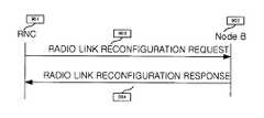
도 9는 SRNC인 RNC A(402)가 Node B1(405)에게 NBAP 메시지를 통한 송신전력 오프셋 값을 제공하기 위한 시그널링의 일 예를 도시한 도면이다. 상기 도 9에서는 송신전력을 전송하기 위한 NBAP 메시지로써 RADIO LINK RECONFIGURATION REQUEST 메시지를 사용하고 있다.9 illustrates an example of signaling for an
SRNC(402)는 Node B1(405)에게 RADIO LINK RECONFIGURATION REQUEST 메시지(903)를 전송한다. 상기 RADIO LINK RECONFIGURATION REQUEST 메시지는 송신전력 오프셋 값을 포함한다. 상기 Node B1(402)는 상기 송신전력 오프셋 값에 의해 채널 자원을 재구성할 수 있다. 상기 Node B1(402)은 상기 RADIO LINK RECONFIGURATION REQUEST 메시지(903)에 대응하여 RADIO RECONFIGURATION RESPONSE 메시지를 SRNC(402)에게 전송한다.
여기서 RADIO LINK RECONFIGURATION REQUEST 메시지(902)에 포함되는 파라미터들을 하기 표 2에 나타내었다.The parameters included in the RADIO LINK

상기 표 2에 나타난 바와 같이 상기 RADIO LINK RECONFIGURATION REQUEST 메시지에 포함되는 파라미터들은 크게 UL_DPCH 정보와 UL_HS-DPCCH, DL_DPCH 정보로 나눌 수 있다. 상기 UL_DPCH 정보에는 UL_DPCH의 전송 포맷 조합인 TFCS 파라미터가 있을 수 있다. 상기 DL_DPCH 정보로는 상기 DL_DPCH의 전송 포맷 조합인 TFCS 와 TFCI 전송방식을 나타내는 TFCI Signaling mode 등의 파라미터가 있을 수 있다. 상기의 정보들은 종래의 3GPP 표준안에 이미 정해져 있는 파라미터들을 나타낸다. 그리고 본 발명에 따른 HS-DPCCH 정보로 RNC A(402)가 Node B1(405)에게 전송해야 하는 송신전력 오프셋 값인 HS-DPCCH power offset 파라미터가 상기 표 2에서 새롭게 정의되고 있다. 상기 Node B1(405)은 상기 송신전력 오프셋 값을 알게 되면 상기 도 8의 (c)에서 보여지듯이 ACK/NACK 판별을 위한 임계선을 결정할 수 있게 된다. 상기 표 2에 나타난 파라미터들은 본 발명의 설명을 쉽게 하기 위해 간략히 필요한 파라미터들만을 나타냈으나 이외에 추가적인 파라미터들이 전송될 수 있다.As shown in Table 2, parameters included in the RADIO LINK RECONFIGURATION REQUEST message can be broadly divided into UL_DPCH information, UL_HS-DPCCH, and DL_DPCH information. The UL_DPCH information may include a TFCS parameter that is a transport format combination of UL_DPCH. The DL_DPCH information may include parameters such as TFCS, which is a transport format combination of the DL_DPCH, and a TFCI signaling mode indicating a TFCI transmission scheme. The above information represents parameters already defined in the conventional 3GPP standard. In addition, the HS-DPCCH power offset parameter, which is a transmission power offset value that the
다음으로 전술한 두 번째 방법에 대해 구체적으로 설명한다.Next, the second method described above will be described in detail.
이때, 도 4에서 RNC A(402)가 UE(419)의 SRNC인 경우를 가정하도록 한다. 두 번째 방법에서 이용되는 프레임 프로토콜(frame protocol)은 제어 프레임(control frame) 구조를 규정하는 공식적인 절차(procedure)로서 프레임 전송을 지원한다. 상기 프레임 프로토콜을 이용하는 두 번째 방법으로는 SRNC인 RNC A(402)가 HSDPA 서비스를 관장하는 Node B1(405)에게 제어 프레임을 전송하는 방법이 있다.In this case, it is assumed in FIG. 4 that the
도 10은 프레임 프로토콜을 이용하여 SRNC가 Node B로 송신전력 오프셋 값을 전송하기 위한 제어 프레임의 일 예를 보이고 있는 도면이다.FIG. 10 is a diagram illustrating an example of a control frame for transmitting a transmission power offset value to a Node B by an SRNC using a frame protocol.
상기 도 10에서 보이고 있듯이 송신전력 오프셋 값을 제어 프레임의 잉여 필드(spare)(1001)에 첨가하여 전송할 수 있다.As shown in FIG. 10, the transmission power offset value may be added to the
상기 프레임 프로토콜을 이용하는 경우에는 상기 RNC A(402)에서 HS-DSCH를 전송하는 cell 1(407)로만 HS-DSCH data frame을 전송하는 방법이 있다.In the case of using the frame protocol, there is a method of transmitting the HS-DSCH data frame only to the
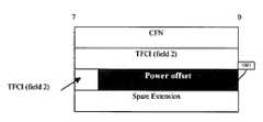
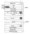
도 11은 프레임 프로토콜을 이용하여 상기 SRNC가 Node B로 송신전력 오프셋을 전송하기 위한 데이터 프레임의 일 예를 보이고 있는 도면이다.FIG. 11 illustrates an example of a data frame for transmitting a transmission power offset to the Node B by the SRNC using a frame protocol.
도 11에서 보여지고 있듯이 송신전력 오프셋 값을 데이터 프레임을 구성하는 헤더(header) 부분의 빈 공간에 첨가하여 전송할 수 있다. 단, 인접한 전력 오프셋(1102)은 HS-DPCCH를 위한 송신전력 오프셋이 아닌, 데이터 전력 오프셋(data power offset)이다. 상기 도 11에서는 본 발명에서 추가되는 송신전력 오프셋 값이 TFI 비트들(bit)과 나란히 있는 잉여 비트들(spare bit)에 추가됨을 보여주고 있다. 이때 잉여비트들(spare bit)은 3비트(bit)이므로 SRNC에서 Node B로 전송 가능한 송신전력 오프셋 값의 경우의 수는 8가지가 될 수 있다.As shown in FIG. 11, a transmission power offset value may be added to an empty space of a header part constituting a data frame and transmitted. However, the adjacent power offset 1102 is a data power offset, not a transmit power offset for the HS-DPCCH. FIG. 11 shows that the transmission power offset value added in the present invention is added to the spare bits parallel to the TFI bits. In this case, since the spare bits are 3 bits, the number of transmission power offset values that can be transmitted from the SRNC to the Node B may be eight.
3. 송신전력 오프 셋에 의한 HS-DPCCH의 송신전력 조절
도 12에서는 본 발명의 제1실시 예에 따른 UE(419)의 제어 흐름을 도시한다.3. Transmission power control of HS-DPCCH by transmission power offset
12 illustrates a control flow of the
단계 1201을 시작으로 UE는 단계 1202에서 상기 도 5의 (b) 또는 (c)와 같이 기본적으로 설정된 송신전력으로 HS-DPCCH를 전송한다. 단계 1203에서 UE는 여러 Node B들로부터의 CPICH들의 수신전력을 측정한다. 이 때 셀 1(407)의 수신전력이 셀 2(408)의 수신전력보다 일정량 크게 되면 event 1A가 발생한다. 단계 1204에서 event 1A가 발생했으면 상기 셀 2(408)을 활성집합에 포함시켜야 함을 인지하고 단계 1205로 진행하여 SRNC에게 측정결과 리포트를 한다. 하지만 상기 단계 1203에서 event 1A가 발생하지 않았으면 상기 UE는 상기 단계 1202로 리턴하여 HS-DPCCH를 기본전력으로 전송하게 된다. 상기 UE는 단계 1205에서 SRNC에게 측정결과를 리포트한 후 UTRAN 측에서 활성집합 업-데이트를 위한 설정이 완료되면 단계 1206으로 진행한다. 상기 측정결과를 수신한 상기 SRNC는 UE에게 HS-DPCCH를 위한 송신전력 오프셋 값이 포함된 ACTIVE SET UPDATE 메시지를 전송한다. 상기 ACTIVE SET UPDATE 메시지는 상기 표 1에 나타난 파라미터들을 포함할 수 있다. 상기 UE는 상기 단계 1206에서 상기 ACTIVE SET UPDATE 메시지를 수신하고, 상기 ACTIVE SET UPDATE 메시지에 포함된 송신전력 오프셋 값을 검사한다. 상기 UE는 상기 송신전력 오프셋 값에 의해 HS-DPCCH에 적용할 송신전력을 결정하고, 상기 송신전력에 의해 상기 HS-DPCCH를 전송한다. 상기 UE는 단계 1206이 성공적으로 수행되면 단계 1207로 진행하여 SRNC에게 ACTIVE SET UPDATE COMPLETE 메시지를 전송한 후 단계 1208에서 동작을 종료한다.Starting from
도 13에서는 본 발명의 제1실시 예에 따른 SRNC의 제어 흐름을 도시한다.13 shows a control flow of the SRNC according to the first embodiment of the present invention.
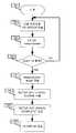
단계 1301을 시작으로 SRNC는 단계 1302에서 UE로부터 측정결과 리포트를 수신한다. 상기 SRNC는 상기 측정결과 리포트에 대응하여 단계 1303에서 상기 표 1과 같이 HS-DPCCH를 위한 송신전력 오프셋 값을 포함하는 ACTIVE SET UPDATE 메시지를 상기 UE에게 전송한다. 그런 후 단계 1304에서 상기 SRNC는 단말에게서 상기 ACTIVE SET UPDATE 메시지가 제대로 수행되었음을 나타내는 ACTIVE SET UPDATE COMPLETE 메시지를 수신한다. 상기 도 8에서 설명했듯이 Node B가 HS-DPCCH의 ACK/NACK 정보를 판단하기 위해서 상기 송신전력 오프셋 값을 알아야 하므로 단계 1305에서는 상기 송신전력 오프셋 값을 상기 Node B에게 전달한다. 본 발명에서는 SRNC가 Node B로 상기 송신전력 오프셋 값을 전송하는 두 가지 방법을 제안하고 있다. 첫 번째 방법으로는 상기 도 9와 같이 SRNC가 Node B에게 표 2와 같이 HS-DPCCH를 위한 송신전력 오프셋 값을 포함하는 RADIO LINK RECONFIGURATION REQUEST 메시지를 전송하고 Node B로부터 RADIO LINK RECONFIGURATION RESPONSE 메시지를 전송 받는 방법이 있다. 두 번째 방법으로는 상기 도 10 또는 상기 도 11과 같이 SRNC가 Node B에게 HS-DPCCH를 위한 송신전력 오프셋이 포함된 HS-DSCH control frame 또는 data frame을 전송하는 방법이 있다. 상기와 같이 SRNC는 Node B에게 송신전력 오프셋 값을 알려준 후 단계 1306에서 모든 동작을 종료한다.Beginning with
도 14는 본 발명의 제1실시 예에 따른 Node B의 제어 흐름을 도시한다.14 illustrates a control flow of Node B according to the first embodiment of the present invention.
단계 1401을 시작으로 단계 1402에서 Node B는 SRNC로부터의 송신전력 오프셋 값을 수신한다. 상기에서 송신전력 오프셋 값은 RADIO LINK RECONFIGURATION REQUEST 메시지를 통해 수신하거나 HS-DSCH의 control 또는 data frame을 통해 전송 받을 수 있다. 상기 Node B는 단계 1403에서 상기 수신한 송신전력 오프셋 값을 반영하여 ACK/NACK을 판별하기 위한 임계선을 결정한 후 단계 1404에서 모든 동작을 종료한다.Beginning at
도 15는 본 발명의 제1실시 예에 따라 상위 계층 시그널링을 통해 송신전력 오프셋 값을 UE에게 전송하기 위한 Node B의 송신장치의 일 예를 제시한다. 상기 도 15에서는 상기 도 7에서 설명한 ACTIVE SET UPDATE 메시지가 DL_DPCH로 전송되는 경우의 node B 송신기를 도시하고 있다. ACTIVE SET UPDATE 메시지를 포함하는 사용자 데이터 1501은 부호기 1502에 의해 채널 부호화된 후 레이트 매칭부 1503에 의해 물리채널에서 전송될 비트수로 레이트 매칭된다. 상기 레이트 매칭부 1503의 출력은 HS-DSCH 지시자 1505, TFCI 1507, Pilot 1508, TPC 1509와 함께 다중화기 1510으로 인가되어 하나의 비트 스트림으로 출력된다. 상기 비트 스트림은 직/병렬 변환기 1511에 의해 두 개의 비트 스트림들로 변환된다. 확산기 1512에서는 상기 두 개의 비트 스트림들을 같은 채널화 코드를 사용해서 확산시켜 다른 채널화 코드를 사용하는 신호들과 직교성을 갖게 된다. 이때, 상기 확산기 1512로부터 출력되는 두 개의 비트 스트림들 중 Q 신호는 곱셈기 1513에 의해 j가 승산되며, 나머지 하나의 비트 스트림인 I신호와 덧셈기 1514에 의해 가산되어 하나의 복소수 스트림으로 출력된다. 상기 복소수 스트림은 혼화기 1515에 의해 칩 단위로 복소 혼화 코드와 곱해져 다른 혼화 코드를 사용하는 신호와 구분이 가능해진다. 상기 혼화기 1515의 출력은 다시 곱셈기 1516에 의해 채널이득과 곱해진다. 상기 채널이득은 DL_DPCH의 송신 전력을 결정하는 파라미터로서, 일반적으로 확산율이 작을 때 큰 값이 곱해진다. 상기 채널이득은 전송되는 사용자 데이터의 종류에 따라 값이 달라진다. 한편, 상기 도 15에서는 SHCCH를 위한 전송장치 또한 도시하고 있는데, HS-DSCH를 위한 제어정보 1517은 직/병렬 변환기 1518에 의해 두 개의 비트 스트림들로 변환된 후 확산기 1519에 의해 확산된다. 상기 확산기 1519로부터 출력되는 두 개의 비트 스트림들 중 Q 신호는 곱셈기 1520에 의해 j가 승산되며, 나머지 하나의 비트 스트림인 I신호와 덧셈기 1521에 의해 가산되어 하나의 복소수 스트림으로 변환된다. 상기 복소수 스트림은 혼화기 1522에 의해 칩 단위로 복소 혼화 코드와 곱해진 후, 곱셈기 1523에서 채널이득과 곱해진다. 상기 곱셈기 1516으로부터의 DL_DPCH와 상기 곱셈기 1523으로부터의 SHCCH는 합산기 1524에서 더해진 후, 변조기 1525에서 변조된다. 상기 변조된 신호는 RF부 1526에서 RF 대역 신호로 바뀐 후 안테나 1527을 통해 송신된다.FIG. 15 shows an example of an apparatus for transmitting a Node B for transmitting a transmission power offset value to a UE through higher layer signaling according to the first embodiment of the present invention. FIG. 15 illustrates a Node B transmitter when the ACTIVE SET UPDATE message described with reference to FIG. 7 is transmitted through DL_DPCH. The
도 16은 상기 도 15에 대응한 UE의 송수신기의 구조도로서 Node B로부터 송신전력 오프셋 값을 수신하여 HS-DPCCH에 대한 송신전력을 조정한 후 다른 역방향 채널들과 함께 전송하는 것을 보이고 있다.
도 16을 참조하면, 사용자 정보 1601은 부호기 1602로 입력되어 길쌈부호 혹은 터보부호로 채널 부호화된 후 레이트 매칭부 1603으로 입력된다. 상기 레이트 매칭부 1603은 상기 부호화 비트 스트림에 대해 심볼 천공 혹은 심볼 반복 및 인터리빙 과정을 수행하여 UL_DPDCH로 전송되기 알맞은 형태로 생성한다. 상기 레이트 매칭부 1603에서 생성된 데이터는 확산기 1604로 입력되어, UL_DPDCH에 대응한 채널 부호로 확산된다. 상기 확산기 1604에서 확산된 사용자 데이터는 승산기 1605에서 채널이득과 곱해진다. 상기 채널 이득이 곱해진 UL_DPDCH 신호는 합산기 1606으로 입력된다. TPC 1607, Pilot 1608, TFCI 1609, FBI 1610은 다중화기 1611에서 다중화되어 하나의 비트 스트림으로 출력되며, 상기 하나의 비트 스트림은 확산기 1612에서 DPCCH에 대응한 채널 부호로 확산된 후, 승산기 1613에서 DPCCH를 위한 채널 이득과 곱해진 후, 승산기 1614에서 복소수 j와 곱해진다. 상기 승산기 1614에서 복소수 j를 곱하는 이유는 UL_DPCCH와 상기 UL_DPDCH를 허수측과 실수측으로 구별함으로써, 무선 주파수(Radio frequency) 상의 성좌도(Constellation)에서 Zero Crossing의 발생 빈도를 줄이기 위함이다. 상기 제로 크로싱의 발생 빈도를 줄이게 되면 UE의 송신기에서 PAR(Peak to Average Ratio:이하 "PAR"이라 칭함)을 작게 할 수 있기 때문이다. 일반적으로 무선 주파수 상의 성좌도에서 zero crossing이 발생하면 PAR이 커지며, 상기 커진 PAR이 UE의 송신기상에 안 좋은 영향을 미친다는 것을 널리 알려진 사실이다. 상기 승산기 1614에 의해 허수 값을 가지는 UL_DPCCH 신호는 상기 합산기 1606으로 입력되어, 상기 UL_DPDCH신호와 합해지나 실수와 허수의 덧셈이기 때문에 각기 성질은 변하지 않는다.FIG. 16 is a structural diagram of a transceiver of a UE corresponding to FIG. 15, and illustrates that a transmission power offset value is received from a Node B, adjusted for a transmission power for an HS-DPCCH, and then transmitted together with other reverse channels.
Referring to FIG. 16, the
ACK/NACK 1615와 CQI 정보 1616은 다중화기 1617에 의해 전송되는 시점이 구분된 후 확산기 1618에 의해 HS-DPCCH를 위한 확산부호로 확산된다. 한편 UE는 수신 안테나 1619으로부터 수신받은 데이터들을 처리하는 수신단 1620을 이용하여 송신전력 오프셋 값 1621을 추출한다. 그러면 제어부 1621은 상기 UL_DPCCH와 일정 전력비를 유지하던 기존 HS-DPCCH의 송신전력이 상기 송신전력 오프셋 값만큼 증가하도록 채널이득을 조정한다. 승산기 1623는 상기 채널 이득과 상기 확산기 1618로부터의 HSDPCCH 신호를 곱한다. 즉, UE는 상기 UL_DPDCH와 상기 UL_DPCCH에 대한 채널이득은 기존 방식대로 적용하고, HS-DPCCH에 대한 채널이득만 송신전력 오프셋 값을 이용해 조정한다. 상기 승산기 1623에서 채널 이득과 곱한 후 상기 합산기 1606으로 입력되는 상기 HS-DPCCH 신호는 상기 UL_DPDCH 신호 및 UL_DPCCH 신호와 합산된다.The ACK /
상기에서 설명한 바와 같이 UL_DPCCH는 복소수 j가 곱해져 허수가 된 값으로 HS-DPCCH와 합해져도 고유의 특성이 없어지지 않으며, 상기 UL_DPDCH와 상기 HS-DPCCH는 각각 다른 채널 부호로 확산되었기 때문에 수신단에서 역확산할 경우 상호 영향이 없어진다. 상기 UL_DPCCH와 달리 상기 HS-DPCCH에 상기 UL_DPDCH를 합하여 I채널로 전송하고 상기 UL_DPCCH를 Q채널로 전송하는 이유는 실수측으로 전송되는 상기 UL_DPDCH상에 사용자 정보 혹은 상위 계층의 시그널링이 없을 경우에는 전송되지 않는 채널이기 때문이다. 만약, 상기 UL_DPDCH가 전송되지 않는 경우에, 허수측으로 두 개의 DPCCH들을 모두 전송한다면, Zero Crossing이 발생하는 빈도가 높아져서 UE 송신기의 PAR이 커질 수 있기 때문에 HS-DPCCH를 실수로 전송함으로써 UE 송신기의 PAR을 최대한 줄이기 위해서 이다. 상기 합산기 1606에서 합산된 UL_DPDCH, UL_DPCCH, HS-DPDCH는 I+J형태로 승산기 1624에서 UE에서 사용하는 역방향 스크램블링 부호가 복소수로 곱해져 혼화된 후, 변조기 1625로 입력되어 변조된다. 상기 변조된 신호는 RF부 1626에서 무선 주파수로 변환되어 안테나 1627을 통하여 Node B로 전송된다. 상기 승산기 1624에서 사용된 역방향 스크램블링 부호는 UMTS에서 UE들을 구별하기 위하여 사용하는 부호로서, 골드 부호로부터 생성되는 복소 부호이다. 상기 승산기 1624에서 사용된 역방향 스크램블링 부호는 상기 UE가 전송한 신호를 수신한 Node B에서 역혼화하는데 다시 사용하게 된다.As described above, the UL_DPCCH is a imaginary value multiplied by a complex number j and is combined with the HS-DPCCH. The inherent characteristics are not lost. Since the UL_DPDCH and the HS-DPCCH are each spread with different channel codes, the receiver is despread. If you do, there is no mutual effect. Unlike the UL_DPCCH, the reason why the UL_DPDCH is added to the HS-DPCCH and transmitted through the I channel and the UL_DPCCH is transmitted through the Q channel is not transmitted when there is no user information or higher layer signaling on the UL_DPDCH transmitted to the real side. This is because it is a channel. If the UL_DPDCH is not transmitted, if both DPCCHs are transmitted to the imaginary side, zero crossing occurs and the PAR of the UE transmitter may increase because the frequency of zero crossing may increase, thereby inadvertently transmitting the HS-DPCCH. To reduce as much as possible. The UL_DPDCH, UL_DPCCH, and HS-DPDCH, summed up in the
전술한 제1실시 예와 같이 UE가 핸드오버 지역에 위치하는 경우만 상위 계층 시그널링으로 HS-DPCCH의 송신전력 오프셋 값을 알려주는 경우는 HS-DPCCH 전력 제어를 유동성 있게 조정하기 힘들다는 단점이 있다. 이러한 단점을 극복하기 위한 방법으로 제2실시 예에서는 Node B가 수신되는 HS-DPCCH의 수신전력을 측정하면서 수신전력에 따라 결정된 송신전력 오프셋 값을 유동성 있게 전송하기 위한 방안을 제안하기로 한다.
<제2실시 예>
이하 본 발명의 제2실시 예로써 송신전력 오프셋 값을 HSDPA 서비스를 위한 고속 매체 접속 제어(Medium Access Control-high speed, 이하 "MAC-hs"라 칭함) 패킷 데이터 유닛(Packet Data Unit, 이하 "PDU"라 칭함)를 통해 전송하는 방법을 살펴보기로 하자.As described in the first embodiment, when the UE transmits the transmission power offset value of the HS-DPCCH through higher layer signaling only when the UE is located in the handover region, it is difficult to flexibly adjust the HS-DPCCH power control. . As a method for overcoming this disadvantage, the second embodiment proposes a method for fluidly transmitting a transmission power offset value determined according to the reception power while measuring the reception power of the received HS-DPCCH.
Second Embodiment
Hereinafter, as a second embodiment of the present invention, a transmission power offset value is referred to as a medium access control-high speed (hereinafter, referred to as "MAC-hs") packet data unit (hereinafter referred to as "PDU") for HSDPA service. Let's take a look at how to transmit via "."
먼저 도 17 및 표 3을 참조하여 본 발명의 제2실시 예에 따른 송신전력 오프셋 값을 Node B가 결정하는 방식 및 상기 송신전력 오프셋 값에 대한 비트들의 예를 제시한다. 통상적으로 UE가 핸드오버 영역에 위치할 시 HS-DPCCH의 송신전력이 감소하는 경우가 발생하나 Node B에서 UE가 핸드오버 영역에 위치해 있는지를 지속적으로 감시하기 어렵다. 그러므로 본 발명에서는 Node B가 목표 SIR(SIRtarget)과 UL_DPCCH로 전송되는 파일럿 비트들로 측정한 상향 SIR(SIRest)의 차가 임계값 1보다 크면 채널의 상태가 좋지 않은 것으로 판단한다.First, referring to FIG. 17 and Table 3, a method of determining a transmission power offset value according to the second embodiment of the present invention and an example of bits for the transmission power offset value will be described. Typically, the transmission power of the HS-DPCCH decreases when the UE is located in the handover area, but it is difficult to continuously monitor whether the UE is located in the handover area in the Node B. Therefore, in the present invention, if the difference between the target SIR (SIRtarget) and the upstream SIR (SIRest) measured by the pilot bits transmitted on the UL_DPCCH is greater than the
여기서 HS-DPCCH의 ACK/NACK 정보와 CQI 정보의 송신전력이 다를 수 있으므로 Node B는 ACK/NACK에 대한 목표 SIR과 CQI에 대한 목표 SIR을 다르게 설정해 놓을 것이다. 한편, 상기 ACK/NACK, CQI 정보는 필요 없을 시 DTX 처리될 것이다. 즉 Node B는 ACK/NACK이 수신될 때는 ACK/NACK에 대한 목표 SIR, 측정 SIR을 비교하고, CQI 정보가 수신될 때는 CQI 정보에 대한 목표 SIR, 측정 SIR을 비교해야 할 것이다. 본 발명에서는 설명의 편의를 위하여 Node B는 ACK/NACK과 CQI에 대한 목표 SIR이 같게 설정해 놓았다고 가정하자.Since the transmission power of the ACK / NACK information and the CQI information of the HS-DPCCH may be different, the Node B will set the target SIR for the ACK / NACK and the target SIR for the CQI differently. Meanwhile, the ACK / NACK and CQI information will be DTX processed when it is not necessary. That is, when the ACK / NACK is received, the Node B should compare the target SIR and the measured SIR for the ACK / NACK, and when the CQI information is received, the target SIR and the measured SIR for the CQI information will be compared. In the present invention, for convenience of explanation, assume that the Node B has the same target SIR for ACK / NACK and CQI.
그런 후 SIR 차를 임계값들과 비교하여 역방향 채널 환경에 따라 송신전력 오프셋 값을 결정하기로 한다. 즉, Node B가 소프트 핸드오버 상황에 위치해 있는 경우로 한정하지 않고 역방향 채널 환경이 좋지 못할 경우 역방향 송신전력을 보상하기로 한다.
도 17은 상위 계층에서의 전력 제어에 있어서 Node B가 목표 SIR(SIRtarget)과 역방향 측정 SIR(SIRest)의 차를 이용해 본 발명의 실시 예에 따른 송신전력 오프셋 값을 결정하는 예를 보인다. 여기서 임계값들은 임의로 지정할 수 있으나 후술될 예에서는 2dB의 배수를 임계값으로 가정한다. 예를 들어 설명하면, 임계값 2dB에 대해서 두 SIR 값의 차가 2dB이상 4dB이하이면 역방향 송신전력 오프셋 값을 2dB로 하여 UE의 역방향 송신전력을 송신전력 오프셋 값 2dB만큼 증가시켜 전송하도록 하는 것이다. 나머지 임계값 4, 6, 8dB에 대해서도 마찬가지로 적용 가능하다. 한편, 본 발명에서는 목표 SIR과 UL_DPCCH의 SIR의 차를 오프셋으로 결정하여 HS-DPCCH의 송신전력만 오프셋만큼 증가시키고 나머지 상기 UL_DPCCH, UL_DPDCH의 송신전력은 기존의 방식을 적용한다. 이 때 HS-DPCCH의 송신전력은 매 순간 기존 UL_DPCCH의 송신전력과의 비에 의해 결정된 전력을 기준으로 하여 채널상황이 좋지 않을 때만 오프셋 값을 더해 주는 것이다.The SIR difference is then compared with the thresholds to determine the transmit power offset value according to the reverse channel environment. That is, the node B is not limited to the soft handover situation, and the reverse transmission power is compensated for when the reverse channel environment is not good.
17 illustrates an example in which a Node B determines a transmission power offset value according to an embodiment of the present invention by using a difference between a target SIR (SIRtarget) and a backward measurement SIR (SIRest) in power control in a higher layer. In this case, the thresholds may be arbitrarily specified, but in the following example, a multiple of 2 dB is assumed as the threshold. For example, when the difference between two SIR values is 2 dB or more and 4 dB or less with respect to a threshold value of 2 dB, the reverse transmission power offset value is set to 2 dB so that the reverse transmission power of the UE is increased by a transmission power offset value of 2 dB. The same applies to the remaining thresholds of 4, 6 and 8 dB. Meanwhile, in the present invention, the difference between the target SIR and the SIR of the UL_DPCCH is determined as an offset, so that only the transmission power of the HS-DPCCH is increased by an offset, and the existing methods are applied to the remaining transmission power of the UL_DPCCH and UL_DPDCH. At this time, the transmission power of the HS-DPCCH is added to the offset value only when the channel condition is not good based on the power determined by the ratio of the transmission power of the existing UL_DPCCH at every moment.
하기 표 3에서는 상기 도 17에서와 같이 결정된 송신전력 오프셋 값들을 순방향으로 전송하기 위한 비트들로 변환시킨 예이다. 상기 송신전력 오프셋 값의 수가 2k개 이면 순방향 전송비트를 k 비트로 정할 수 있다. 하기 표 3에서는 오프셋 값 0, 2, 4, 6dB의 4가지이므로 2비트로 표현 가능하며 각각 00, 01, 10, 11을 전송 비트를 결정해 줄 수 있다.Table 3 below is an example of converting the transmission power offset values determined as shown in FIG. 17 into bits for forward transmission. If the number of transmission power offset values is 2k, the forward transmission bit may be determined as k bits. In Table 3 below, four offset

본 발명의 제2실시 예는 Node B가 상기 도 17과 상기 표 3의 방법으로 결정한 HS-DPCCH의 송신전력 오프셋 비트를 MAC-hs PDU와 함께 UE에게 전송하는 방안으로서 상기 MAC-hs PDU 구조를 도 18를 참조하여 설명하기로 한다. 상기 도 18은 본 발명의 또 다른 실시 예에 따른 고속 매체 접속 제어 패킷 데이터 유닛 구조를 도시한 도면이다.In a second embodiment of the present invention, Node B transmits the transmission power offset bits of the HS-DPCCH determined by the method of FIG. 17 and Table 3 to the UE together with the MAC-hs PDU. This will be described with reference to FIG. 18. 18 is a diagram illustrating a structure of a fast medium access control packet data unit according to another embodiment of the present invention.
상기 도 18을 참조하면, MAC-hs PDU는 MAC-hs 헤더(header)(1811) 필드와, MAC-hs 서비스 데이터 유닛(SDU: Service Data Unit)+MAC-hs 제어 메시지(MAC-hs control message)(1813) 필드와, CRC(1815) 필드로 구성된다. 상기 MAC-hs 헤더(1811)는 다수의 정보들을 포함하며, 상기 다수의 정보들은 다음과 같다.Referring to FIG. 18, the MAC-hs PDU includes a MAC-
(1) 우선 순위(Priority): MAC-hs SDU(1813)의 우선 순위 큐(Priority Queue)의 식별자이며, 3비트가 할당됨.(1) Priority: Identifier of the priority queue of the MAC-
(2) 전송 시퀀스 번호(Transmission Sequence Number, 이하 "TSN"이라 칭함): 우선순위 큐에서 MAC-hs SDU(1813)가 재정렬(re-ordering)될 때 사용하는 일련 번호이며, 5비트 내지 6비트가 할당됨.(2) Transmission Sequence Number (hereinafter referred to as "TSN"): A serial number used when the MAC-
(3) SID_x: MAC-hs SDU(1813)를 구성하는 MAC-d(MAC dedicated, 이하 "MAC-d"라 칭함) PDU들의 집합 중 x 번째 MAC-d PDU 집합에 속하는 MAC-d PDU들의 크기를 나타내며, 2비트 내지 3비트가 할당됨(3) SID_x: Size of MAC-d PDUs belonging to the x-th MAC-d PDU set among the set of MAC-d (MAC dedicated, hereinafter referred to as "MAC-d") PDUs forming the MAC-
(4) N_x: x 번째 MAC-d PDU 집합에 속하는 MAC-d PDU들의 개수를 나타내며, 7비트가 할당됨.(4) N_x: Indicates the number of MAC-d PDUs belonging to the x-th MAC-d PDU set, and 7 bits are allocated.
(5) F (Flag) : 상기 F값이 1로 설정될 경우에는 다음에 오는 필드가 MAC-hs SDU임을 나타내고, 상기 F값이 0으로 설정될 경우에는 다음에 오는 필드가 SID임을 나타내는 플래그임. 1비트가 할당됨.(5) F (Flag): When the F value is set to 1, it indicates that the next field is MAC-hs SDU, and when the F value is set to 0, it is a flag indicating that the next field is SID. . 1 bit is allocated.
(6) SID_MAC_C(601) : SID_x와 동일한 크기를 가지며, 아무런 의미를 가지지 않는 정보임. 송신기 및 수신기 모두 상기 SID_MAC_C 값은 무시.(6) SID_MAC_C (601): Information having the same size as SID_x and having no meaning. Both transmitter and receiver ignore the SID_MAC_C value.
(7) C_I(602) : N_x와 F를 합친 크기와 동일한 크기를 가지며, MAC-hs PDU에 MAC-hs 제어 메시지가 존재하는지 여부를 나타냄. C_I에서 N_x에 해당하는 부분은 N_x에서 사용하지 않는 값을 이용해서 항상 동일한 값으로 코딩됨. 수신기는 MAC-hs 헤더의 마지막 N_x 부분에 미리 설정한 값이 수신되면 MAC-hs PDU에 MAC-hs 제어 메시지가 포함되어 있는 것으로 판단함. 본 발명에서는 상기 마지막 N_x 부분에 설정하는 값을 '0000000'으로 고정함. 그러므로, C_I는 항상 '0000000 1'로 세팅되어 있음.(7) C_I 602: has the same size as the sum of N_x and F, and indicates whether a MAC-hs control message exists in the MAC-hs PDU. The part corresponding to N_x in C_I is always coded with the same value using an unused value in N_x. The receiver determines that a MAC-hs control message is included in the MAC-hs PDU when a preset value is received in the last N_x portion of the MAC-hs header. In the present invention, the value set in the last N_x part is fixed to '0000000'. Therefore, C_I is always set to '0000000 1'.
(8) MAC_hs 제어 메시지: MAC-hs SDU 다음에 위치하며, MAC-hs 제어 파트 헤더(control part header)와 플래그(Flag)(606) 및 MAC-hs 제어 페이로드(control payload)(607)부분으로 구성됨. 상기 MAC-hs 제어 파트 헤더는 타입(TYPE)(604) 필드와 사이즈(605)(SIZE) 필드로 구성됨. 여기서, 상기 TYPE(604) 필드는 상기 MAC-hs 제어 메시지의 종류를 나타내며 3 비트로 구성된다. 그리고 상기 TYPE(604) 필드는 하기 표 4에 나타낸 바와 같은 의미를 가진다.(8) MAC_hs control message: located after the MAC-hs SDU, the MAC-hs control part header and flag (606) and the MAC-hs control payload (607) Consists of The MAC-hs control part header is composed of a type (TYPE) 604 field and a size 605 (SIZE) field. Here, the

상기 SIZE(605) 필드는 MAC-hs 제어 메시지의 크기를 비트(bit) 단위로 나타내며, 13비트가 할당된다. 상기 Flag(606)는 해당 MAC-hs 제어 메시지 이후에 또 다른 MAC-hs 제어 메시지의 존재여부를 나타낸다. 그리고 상기 MAC-hs 제어 페이로드는 MAC-hs 제어 메시지의 실제 데이터를 구성하는 부분이다.The
도 19는 본 발명의 제 2 실시 예에 따른 고속 매체 접속 제어 패킷 데이터 유닛의 또 다른 구조를 도시한 도면이다.FIG. 19 is a diagram illustrating another structure of a fast medium access control packet data unit according to a second embodiment of the present invention.
상기 도 19에서는 상기 도 18에서의 SID_MAC_C(601)과 C_I(602) 정보를 사용하지 않고 MAC-hs PDU에 MAC-hs 제어 메시지가 존재하는지 여부를 나타내기 위하여 한 비트의 C_F 플래그(608)를 사용할 수 있다. 상기 C_F 플래그(608)는 MAC-hs PDU의 맨 앞 부분에 위치하거나 우선순위(Priority) 필드 바로 뒤 혹은 전송 시퀀스 번호(TSN) 바로 뒤에도 위치할 수 있다. 상기 C_F 플래그(608)의 지시로 존재하는 MAC-hs 제어 메시지는 MAC-hs SDU의 맨 앞에 위치하거나 혹은 도 18에서와 같이 MAC-hs SDU의 맨 뒤에 위치할 수 있다.In FIG. 19, one bit of the
그러면 여기서 상기 MAC-hs 제어 페이로드의 구성을 설명하기로 한다.The configuration of the MAC-hs control payload will now be described.
상기 MAC-hs 제어 페이로드는 상기 MAC-hs 제어 메시지의 종류에 따라 결정된다. 일 예로 상기 MAC-hs 제어 페이로드 구성은 도 20에 도시한 바와 같으며, 상기 도 20을 참조하여 MAC-hs 제어 페이로드 구성을 설명하기로 한다. 상기 도 20은 본 발명의 제 2 실시 예에 따른 MAC-hs 제어 페이로드(control payload) 구조를 도시한 도면이다.The MAC-hs control payload is determined according to the type of the MAC-hs control message. As an example, the configuration of the MAC-hs control payload is as shown in FIG. 20, and the configuration of the MAC-hs control payload will be described with reference to FIG. 20. 20 illustrates a structure of a MAC-hs control payload according to a second embodiment of the present invention.
상기 도 20을 참조하면, 메시지의 타입이 HS-DPCCH power offset으로 설정된 경우이며 상기 표 3과 같은 방법으로 결정된 HS-DPCCH를 위한 송신전력 오프셋 비트를 상기 도 20의 페이로드로 전송될 것이다. 상기 도 20의 사이즈 필드에는 MAC-hs 제어 페이로드의 크기 2 비트를 의미하는 '00000000000010'이 삽입되며, FLAG 필드에는 이 후에 MAC-hs 제어 메시지의 존재 여부에 따라 해당하는 값이 삽입된다. 그리고 상기 MAC-hs 제어 페이로드 부분에는 HS-DPCCH를 위한 송신전력 오프셋 비트가 삽입된다.Referring to FIG. 20, the message type is set to the HS-DPCCH power offset and the transmission power offset bits for the HS-DPCCH determined by the method shown in Table 3 will be transmitted to the payload of FIG. In the size field of FIG. 20, '00000000000010', meaning 2 bits of the MAC-hs control payload, is inserted, and a corresponding value is inserted into the FLAG field according to the presence or absence of a MAC-hs control message. In the MAC-hs control payload portion, a transmission power offset bit for an HS-DPCCH is inserted.
도 21은 Node B 수신기의 구조도로서, UE로부터 Node B로 전송되는 UL_DPCH와 이로부터 도 17의 방식대로 node B가 역방향 송신전력 오프셋 값을 결정하는 블록을 도시한 도면이다.FIG. 21 is a structural diagram of a Node B receiver, illustrating a UL_DPCH transmitted from a UE to a Node B and a block in which the Node B determines a reverse transmission power offset value according to the scheme of FIG. 17.
상기 도 21을 참조하면, 안테나 2101을 통해서 수신된 UE로부터의 신호는 RF부 2102를 통해 기저 대역(Baseband)의 RF신호로 변환된 후, 복조기 2103에서 복조되어 승산기 2104에서 스크램블링 부호로 곱해져 역혼화된다.Referring to FIG. 21, a signal from a UE received through an
상기 승산기 2104에서 출력된 신호는 역확산기 2105, 2106, 2107로 입력되어 역확산된다. 상기 역확산기 2105에서 사용하는 채널부호는 도 14의 확산기 1404에서 사용하는 채널 부호와 동일하며, 상기 역확산기 2106에서 사용하는 채널 부호는 상기 도 14의 확산기 1412에서 사용하는 채널부호와 동일하고, 상기 역확산기 2107에서 사용하는 채널 부호는 도 14의 확산기 1418에서 사용하는 채널부호와 동일하다. 상기 채널 부호는 직교 부호이기 때문에 상기 역확산기 2105, 2106, 2107에서 역확산된 신호들은 UL_DPDCH, UL_DPCCH, HS-DPCCH로 구별된다. 상기 역확산된 UL_DPCCH는 승산기 2111에서 -j가 곱해져서, 실수신호로 복원된다. 상기 -j가 곱해지는 이유는 도 14의 승산기 1414에서 j가 곱해져 허수신호가 된 UL_DPCCH를 실수신호로 만들기 위함이다. 상기 실수 신호가 된 UL_DPCCH는 역다중화기 2119와 승산기 2112로 입력된다.The signal output from the
상기 역다중화기 2119에서는 UL_DPCCH를 통해 수신되는 신호들 중 역방향 채널추정을 위한 파일럿 신호 2114만을 구별해내어 채널 추정기 2118와 채널상태 결정기 2125으로 입력시킨다. 상기 채널상태 결정기 2125은 본 발명에 따른 역방향 송신전력 오프셋 값을 UE에게 전송할 지를 결정한다. 이를 위해 상기 채널상태 결정기 2125는 상기 파일럿 신호 2114로부터 측정된 SIR과 목표 SIR과의 차를 구하여 상기 차가 임계값보다 큰 지를 판별한다. 그러면 전송전력 결정기 2126에서는 본 발명에 따른 일 예인 상기 도 17과 표 3의 방식을 따라 상기 SIR 차와 임계값들을 비교하여 역방향 송신전력 오프셋 값 2127을 결정하게 된다.The
상기 채널 추정기 2118로 입력된 파일럿 신호 2114는 UE로부터 Node B까지의 채널 환경을 추정하게 하는 데이터로 사용되며 상기 추정된 채널 환경에 대한 보상값이 채널 추정기 2118에서 계산되어 승산기 2112, 승산기 2108, 승산기 2121로 입력된다. 상기 UL_DPCCH는 승산기 2112로 입력되어 채널 추정기 2118에서 계산된 채널 환경에 대한 보상값인 채널 추정 값과 곱해져 역다중화기 2113으로 입력된다. 상기 역다중화기 2113에서는 상기 UL_DPCCH를 통해 수신되는 신호들 중 파일럿 2114을 제외한 TPC 2115, TFCI 2116, FBI 2117을 역다중화한다. 상기 TPC 2115는 순방향 송신 전력의 제어에, TFCI는 UL_DPDCH의 해석에, FBI는 페루프 송신 안테나의 이득 조정에 사용된다. 상기 승산기 2104에서 출력된 신호는 역확산기 2105에서 역확산되어 UL_DPDCH의 신호로 복원된다. 상기 역확산기 2105에서 상기 UL_DPDCH외에 다른 신호들은 없어진다. 상기 복원된 UL_DPDCH 신호는 승산기 2108에서 채널 추정값과 곱해진 후, 복호기 2109에서 사용된 채널 부호, 즉 길쌈부호 혹은 터보 부호에 따라 복호되어 사용자 정보 혹은 상위 계층의 시그널링 신호 2128로 복원되어 상위 계층으로 전달된다. 상기 승산기 2104에서 출력된 신호는 역확산기 2107에 역확산되어 HS-DPCCH의 신호로 복원되는데, 상기 역확산기 2107에서 HS-DPCCH외의 다른 신호들은 없어진다. 상기 HS-DPCCH는 승산기 2121에서 채널추정기 2118에서 출력된 채널 추정값이 곱해져 채널 보상된 후 역다중화기 2122를 통해 ACK/NACK이 수신될 때는 ACK/NACK 2123을 다른 제어정보가 수신될 때는 CQI 정보 2124를 목적에 맞게 사용된다.The
도 22에서는 본 발명의 제 2 실시 예에 따라 HS-DPCCH를 위한 송신전력 오프셋 비트가 MAC-hs PDU, 즉 HS-DSCH로 전송되는 경우 Node B 송신기를 도시하고 있다.FIG. 22 illustrates a Node B transmitter when a transmit power offset bit for an HS-DPCCH is transmitted in a MAC-hs PDU, that is, an HS-DSCH according to a second embodiment of the present invention.
먼저 HS-DSCH를 통한 순방향 고속 패킷 데이터(2201)와 함께 상기 도 21에서 결정한 송신전력 오프셋 값을 상기 표 3을 이용해 변환된 HS-DPCCH power offset 비트(2215)를 MAC-hs PDU 생성기(2223)의 입력으로 인가한다. 상기 MAC-hs PDU 생성기(2223)는 상기 고속 패킷 데이터(2201)와 상기 송신전력 오프셋 값(2215)을 이용해 상기 도 18과 같은 구조를 가지는 MAC-hs PDU를 생성하게 된다. 이 때 MAC-hs 제어 페이로드는 상기 도 19와 같은 구조를 가지고 상기 페이로드에 상향 오프셋 비트가 전송되는 것이다.First, the HS-DPCCH power offset
상기 MAC-hs PDU 생성기(2223)의 출력은 부호기 2202로 입력되어져 부호를 통해 부호화 심볼들로 출력되어진다. 상기 부호 심볼들은 레이트 매칭기 2203에 입력되어져, 상기 부호 심볼들을 심볼 반복 및 천공하여 전송구간(TTI-Transmition time interval)에 상기 심볼들을 전송할 수 있는 심볼 수 만큼으로 맞추어 출력한다. 상기 레이트 매칭되어진 심볼들은 인터리버 2204로 입력되어 인터리빙이 이루어진 후 변조기 2205로 인가된다. 상기 변조기 2205는 상기 입력되어진 인터리빙되어진 심볼들을 QPSK, 8-PSK, M-ary QAM과 같은 신호로 변조하여 비트 스트림으로 출력한다. 상기 비트스트림은 직/병렬 변환기 2206에 의해 두 개의 비트 스트림들로 변화되고 확산기 2207에서는 상기 두 개의 비트 스트림들을 같은 채널화 코드를 사용해서 확산시켜 다른 채널화 코드를 사용하는 신호들과 직교성을 갖게 된다. 이때, 상기 확산기 2207로부터의 두 개의 비트 스트림 I, Q 신호는 곱셈기 2208과 덧셈기 2209에 의해 하나의 복소수 스트림으로 출력된다. 상기 복소수 스트림 출력은 혼화기 2210에 의해 칩 단위로 복소 혼화 코드와 곱해져 다른 혼화 코드를 사용하는 신호와 구분이 가능해진다. 상기 혼화기 2210의 출력은 다시 곱셈기 2211에 의해 채널이득 2212와 곱해진다. 상기 채널이득은 HS-DSCH의 송신 전력을 결정하는 파라미터로서, 일반적으로 확산율이 작을 때 큰 값이 곱해지며, 또한 전송되는 사용자 데이터의 종류에 따라 값이 달라진다.The output of the MAC-
DL_DPCH를 통해 전송될 데이터 2216은 부호기 2202에 의해 채널 부호화되고 레이트 매칭부 2218에 의해 물리채널에서 전송될 비트수로 레이트 매칭된다. 상기 레이트 매칭이 이루어진 데이터는 인터리버 2219에서 인터리빙 된 후 변조기 2220에서 변조된다. 상기 변조기 2220 출력은 HS-DSCH 지시자 2222, TFCI 2224, Pilot 2225, TPC 2226과 함께 다중화기 2227에 인가되어 하나의 비트 스트림들로 출력된다. 상기 비트 스트림은 직/병렬 변환기 2228에 의해 두 개의 비트 스트림으로 변화되고 확산기 2229에서는 상기 두 개의 비트 스트림들을 같은 채널화 코드를 사용해서 확산시켜 다른 채널화 코드를 사용하는 신호들과 직교성을 갖게 된다. 이때, 상기 확산기 2229로부터의 두 개의 비트 스트림 I, Q 신호는 곱셈기 2230과 덧셈기 2231에 의해 하나의 복소수 스트림으로 출력된다. 상기 복소수 스트림 출력은 혼화기 2232에 의해 칩 단위로 복소 혼화 코드와 곱해져 다른 혼화 코드를 사용하는 신호와 구분이 가능해진다. 상기 혼화기 2232의 출력은 다시 곱셈기 2233에 의해 채널이득 2234과 곱해진다. 한편, 상기 도 22에서는 SHCCH를 위한 전송장치 또한 도시하고 있는데, HS-DSCH 제어정보 2235는 직/병렬 변환기 2236에 의해 두 개의 비트 스트림들로 변환되며 확산기 2237에 의해 확산되고, 다시 곱셈기 2238와 가산기 2239에 의해 하나의 복소수 스트림으로 변환된다. 상기 가산기 2239의 복소수 출력은 혼화기 2240에 의해 칩 단위로 복소 혼화 코드와 곱해진 후, 곱셈기 2241에서 채널이득 2242와 곱해진다. 상기 곱셈기 2211로부터 출력되는 HS-DSCH 신호와 상기 곱셈기 2233으로부터 출력되는 DL_DPCH 신호와 상기 곱셈기 2241로부터 출력되는 SHCCH 신호는 합산기 2243에서 더해진 후, 필터 2244에 의해 필터링된다. 상기 필터링된 신호는 RF부 2245에서 RF 대역 신호로 바뀐 후 안테나 2246을 통해 송신된다.
도 23은 상기 도 22의 구조에 대응하여 본 발명의 제2실시 예에 따른 UE의 수신 장치의 예를 나타낸 도면이다.FIG. 23 is a diagram illustrating an example of a reception device of a UE according to the second embodiment of the present invention corresponding to the structure of FIG. 22.
상기 도 23을 참조하면, 안테나(2301)에 의해 수신된 RF 대역 신호는 RF부(2302)에 의해 기저대역신호로 변환된 후 필터(2303)에 의해 필터링되어 세 개의 역혼화기 2304, 2316, 2327에 인가된다. 상기 역혼화기 2304에서는 HS-DSCH 신호가 출력되며 상기 역혼화기 2316에서는 DL_DPCH 신호가 출력되며, 상기 역혼화기 2327에서는 SHCCH 신호가 출력된다. 상기 역혼화기 2304의 복소수 출력은 채널 분리기 2305에 의해 실수신호인 I신호와 허수신호인 Q신호로 분리되며, 상기 I신호와 Q 신호는 역확산기 2306에서 채널화 코드가 곱해져서 각각 역확산된다. 상기 역혼화기 2316의 복소수 출력은 채널 분리기 2317에 의해 실수신호인 I신호와 허수신호인 Q신호로 분리되며, 상기 I신호와 Q 신호는 역확산기 2318에서 채널화 코드가 곱해져서 각각 역확산된다. 또한 채널 분리기 2328로부터 출력되는 I신호와 Q 신호는 역확산기 2329에서 채널화 코드가 곱해져서 각각 역확산된다.
상기 역확산기(2318)에 의해 역확산된 I신호와 Q신호는 역다중화기(2307)에 인가되며, 상기 역다중화기(2307)는 파일럿(pilot) 신호 2308을 출력하게 된다. 상기 파일럿(pilot) 신호2308은 채널추정기(2309)에 인가되어 무선채널에 의한 왜곡 추정을 통한 채널 추정치가 채널보상기 2310, 2319, 2330에 인가한다. 상기 채널보상기 2310, 2319, 2330은 상기 채널 추정치를 이용하여 무선채널에 의한 왜곡을 보상하게 된다. 상기 채널보상기 2310은 HS-DSCH의 데이터를 두 개의 비트 스트림들로 출력하며, 상기 채널보상기 2319는 DL_DPCH의 데이터를 두 개의 비트 스트림들로 출력하며, 상기 채널보상기 2330은 SHCCH의 데이터를 두 개의 비트 스트림들로 출력한다. 병/직렬 변환기 2311은 두 개의 비트 스트림들로 인가된 HS-DSCH 데이터를 하나의 비트 스트림으로 변환시킨다. 상기 병/직렬 변환기 2331은 두 개의 비트 스트림들로 인가된 SHCCH 데이터를 하나의 비트 스트림으로 변환시켜 최종적으로 상기 HS-DSCH에 대한 제어정보 2332를 출력하게 된다. 상기 병/직렬 변환기 2320은 두 개의 비트 스트림으로 인가된 DL_DPCH의 데이터를 하나의 비트 스트림으로 변환시키며, 상기 병/직렬 변환기 2320의 출력 비트 스트림은 역다중화기(2321)에 의해 TPC(2322), TFCI(2323), HS-DSCH 지시자(2324)로 출력된다. 또한, 상기 역다중화기(2321)는 역다중화를 통해 순방향 데이터 신호를 출력하며, 상기 순방향 데이터 신호는 복조기 2333과 디인터리버 2334, 복호기(2335)에 의해 채널 복호화되어 순방향 사용자 데이터(2336)로 출력된다.Referring to FIG. 23, the RF band signal received by the
The I and Q signals despread by the
상기 병/직렬 변환기 2311는 HS-DSCH를 통한 데이터 신호를 출력하는데, 상기 데이터신호는 복조기 2312와 디인터리버 2313, 복호기 2314에 의해 채널 복호화되어 MAC-hs PDU 해석기(2325)로 인가된다. 상기 MAC-hs PDU 해석기(2325)는 상기 도 22에서 설명한 MAC-hs PDU 생성기(2223)와 반대의 과정을 수행한다. 즉 상기 MAC-hs PDU 해석기(2325)는 상기 복호기(2314)로부터 출력되는 데이터로부터 고속 패킷 데이터(2315)와 HS-DPCCH를 위한 송신전력 오프셋 값(2326)을 추출하는 장치가 되는 것이다. 상기 송신전력 오프셋 값(2326)은 상기 도 19에서 설명한 MAC-hs 제어 페이로드로부터 추출한 정보가 된다. UE는 전술한 과정에 의해 추출한 송신전력 오프셋 값을 상기 도 16에서 보이고 있는 구성에 적용함으로써 HS-DPCCH을 송신할 수 있다. 즉, 상기 도 16에서의 제어부(1622)는 상기 송신전력 오프셋 값(2326)을 이용하여 채널이득을 조정하는 것이다.The parallel /
도 24 및 도 25에서는 본 발명의 제2실시 예에 따른 역방향 송신전력 오프셋 값을 처리하기 위해 Node B 및 UE에서 수행하는 제어 흐름을 도시한다.24 and 25 illustrate control flows performed by the Node B and the UE to process the reverse transmission power offset value according to the second embodiment of the present invention.
상기 도 24는 Node B가 역방향 송신전력 오프셋 값을 결정하고 이를 UE에게 알려주기 위한 제어 흐름을 도시한 것이다.
상기 도 24를 참조하면, 단계 2401을 시작으로 Node B는 단계 2402에서 수신한 HS-DPCCH의 SIR을 측정한다. 상기 Node B는 단계 2403에서 상기 측정된 SIR과 함께 목표 SIR을 비교하여 상기 도 17과 표 3과 같이 HS-DPCCH를 위한 송신전력 오프셋 비트를 결정한다. 그러면 단계 2404에서 상기 Node B는 상기 송신전력 오프셋 비트를 전송하기 위한 MAC-hs 제어 메시지를 생성한다. 상기 MAC-hs 제어 메시지의 일 예는 도 20에서 보이고 있는 바와 같다. 단계 2405에서 상기 Node B는 상위 계층에서 내려온 패킷 데이터와 MAC-hs 제어 메시지를 묶어 MAC-hs PDU를 생성한다. 상기 MAC-hs PDU의 예는 도 18과 도 19에서 보이고 있는 바와 같다. 그런 후 상기 Node b는 상기 MAC-hs PDU를 디코딩하여 인터리빙한 후 HS-DSCH를 통해 UE에게 전송한 후 단계 2406에서 모든 동작을 종료한다.FIG. 24 illustrates a control flow for Node B to determine a reverse transmit power offset value and inform the UE of this.
Referring to FIG. 24, starting with
상기 도 25는 UE가 역방향 송신전력 오프셋 값을 처리하기 위한 제어 흐름을 도시한 것이다.25 illustrates a control flow for a UE to process a reverse transmission power offset value.
상기 도 25를 참조하면, 단계 2501을 시작으로 단계 2502에서 UE는 Node B가 전송한 HS-DSCH를 수신한다. 그 후 상기 UE는 단계 2503에서 상기 HS-DSCH를 통해 수신한 MAC-hs PDU로부터 송신전력 오프셋 값을 추출한다. 단계 2504에서는 상기 추출한 송신전력 오프셋 값을 이용해 HS-DPCCH의 송신전력을 조정하고, 상기 조정한 송신전력에 의해 상기 HS-DPCCH를 전송한다. 단계 2505에서는 HS-DPCCH에 대한 송신전력을 결정하는 모든 동작을 종료한다.Referring to FIG. 25, starting with
상술한 바와 같은 본 발명은 고속 순방향 패킷 접속 방식을 사용하는 이동통신 시스템에서 임의의 UE에 할당되는 순방향 송신전력과 같은 제어 정보들을 전송함에 있어 Node B와 UE간 직접 전송을 가능하게 한다는 이점을 가진다. 또한 상기 Node B와 UE간에 제어 정보들을 직접 전송함으로써 Node B와 UE간 신호 지연을 줄이고, Iub 전송 자원을 절약할 수 있어 시스템 성능을 향상시킨다는 이점을 가진다.As described above, the present invention has the advantage of enabling direct transmission between a Node B and a UE in transmitting control information such as a forward transmission power allocated to an arbitrary UE in a mobile communication system using a fast forward packet access scheme. . In addition, by directly transmitting control information between the Node B and the UE, it is possible to reduce signal delay between the Node B and the UE and save Iub transmission resources, thereby improving system performance.
또한 본 발명에서 고속 매체 접속 제어 패킷 데이터 유닛을 통해 오프셋을 전송하는 경우 역방향 송신전력을 유동성 있게 조정할 수 있다.In the present invention, when the offset is transmitted through the high speed medium access control packet data unit, the reverse transmission power can be flexibly adjusted.
Claims (31)
Translated fromKoreanPriority Applications (9)
| Application Number | Priority Date | Filing Date | Title |
|---|---|---|---|
| KR20020008873AKR100832117B1 (en) | 2002-02-17 | 2002-02-17 | Apparatus and method for transmitting and receiving reverse transmission power offset information in mobile communication system using high speed forward packet access method |
| CA 2419005CA2419005C (en) | 2002-02-17 | 2003-02-17 | Apparatus and method for transmitting and receiving uplink power offset information in a mobile communication system supporting hsdpa |
| JP2003038863AJP3943040B2 (en) | 2002-02-17 | 2003-02-17 | Apparatus and method for transmitting / receiving reverse transmission power offset information in a mobile communication system using a high-speed forward packet connection method |
| CNB031360149ACN100542351C (en) | 2002-02-17 | 2003-02-17 | Apparatus and method for transmitting and receiving uplink power offset information |
| AU2003200543AAU2003200543B2 (en) | 2002-02-17 | 2003-02-17 | Apparatus and method for transmitting and receiving uplink power offset information in a mobile communication system supporting HSDPA |
| RU2003104616ARU2251220C2 (en) | 2002-02-17 | 2003-02-17 | Device and method for transferring and receiving data about deviation of power of ascending communication line in cell phone network, supporting high-speed packet access via descending communication line |
| EP03003598.4AEP1341318B1 (en) | 2002-02-17 | 2003-02-17 | Apparatus and method for transmitting and receiving uplink power offset information in a mobile communication system supporting HSDPA |
| EP16156001.6AEP3038416B1 (en) | 2002-02-17 | 2003-02-17 | Apparatus and method for transmitting and receiving uplink power offset information in a mobile communication system supporting hsdpa |
| US10/370,401US7054633B2 (en) | 2002-02-17 | 2003-02-19 | Apparatus and method for transmitting and receiving uplink power offset information in a mobile communication system supporting HSDPA |
Applications Claiming Priority (1)
| Application Number | Priority Date | Filing Date | Title |
|---|---|---|---|
| KR20020008873AKR100832117B1 (en) | 2002-02-17 | 2002-02-17 | Apparatus and method for transmitting and receiving reverse transmission power offset information in mobile communication system using high speed forward packet access method |
Publications (2)
| Publication Number | Publication Date |
|---|---|
| KR20030068998A KR20030068998A (en) | 2003-08-25 |
| KR100832117B1true KR100832117B1 (en) | 2008-05-27 |
Family
ID=27725785
Family Applications (1)
| Application Number | Title | Priority Date | Filing Date |
|---|---|---|---|
| KR20020008873AExpired - Fee RelatedKR100832117B1 (en) | 2002-02-17 | 2002-02-17 | Apparatus and method for transmitting and receiving reverse transmission power offset information in mobile communication system using high speed forward packet access method |
Country Status (8)
| Country | Link |
|---|---|
| US (1) | US7054633B2 (en) |
| EP (2) | EP3038416B1 (en) |
| JP (1) | JP3943040B2 (en) |
| KR (1) | KR100832117B1 (en) |
| CN (1) | CN100542351C (en) |
| AU (1) | AU2003200543B2 (en) |
| CA (1) | CA2419005C (en) |
| RU (1) | RU2251220C2 (en) |
Families Citing this family (239)
| Publication number | Priority date | Publication date | Assignee | Title |
|---|---|---|---|---|
| US6915473B2 (en) | 2001-05-14 | 2005-07-05 | Interdigital Technology Corporation | Method and system for implicit user equipment identification |
| SE522538C2 (en)* | 2001-08-11 | 2004-02-17 | Samsung Electronics Co Ltd | Method of reducing the number of bits needed to transmit orthogonal code information over a control channel in an HSDPA system |
| EP1486089A1 (en)* | 2002-03-08 | 2004-12-15 | Nokia Corporation | Enhanced and device for controlling the power in an asymmetric soft handover condition |
| US8619718B2 (en) | 2002-04-05 | 2013-12-31 | Interdigital Technology Corporation | Method and apparatus for coordinating a radio network controller and node B resource management for high speed downlink packet data service |
| US6717927B2 (en) | 2002-04-05 | 2004-04-06 | Interdigital Technology Corporation | System for efficient recovery of node B buffered data following serving high speed downlink shared channel cell change |
| JP2005525057A (en) | 2002-05-09 | 2005-08-18 | ノキア コーポレイション | HSDPACQI, ACK and NACK power offsets recognized at Node B and SRNC |
| KR100891816B1 (en)* | 2002-05-11 | 2009-04-07 | 삼성전자주식회사 | A method of transmitting power offset information of high speed forward physical shared channel in asynchronous code division multiple access mobile communication system |
| KR20040016330A (en)* | 2002-08-16 | 2004-02-21 | 삼성전자주식회사 | Apparatus for controlling transmission power of high speed shared information channel in time division duplexing code division multiple access communication system using high speed downlink packet access scheme and method thereof |
| US7706405B2 (en) | 2002-09-12 | 2010-04-27 | Interdigital Technology Corporation | System for efficient recovery of Node-B buffered data following MAC layer reset |
| KR100584431B1 (en)* | 2003-02-14 | 2006-05-26 | 삼성전자주식회사 | System and method for uplink data retransmission in code division multiple access communication system |
| GEP20094593B (en) | 2003-03-26 | 2009-01-26 | Interdigital Tech Corp | Wireless multi-cell communication system for managing resource power to provide high speed downlink packet access services |
| AU2007202889B2 (en)* | 2003-03-26 | 2009-03-19 | Interdigital Technology Corporation | Wireless multi-cell communication system and method for managing resource power to provide high speed downlink packet access services |
| SE0301400D0 (en)* | 2003-05-12 | 2003-05-12 | Ericsson Telefon Ab L M | A method in a telecommunication system |
| JP2007521750A (en)* | 2003-06-26 | 2007-08-02 | インターデイジタル テクノロジー コーポレーション | A method for generating a channel quality indicator by biasing the signal-to-interference ratio. |
| US7925291B2 (en)* | 2003-08-13 | 2011-04-12 | Qualcomm Incorporated | User specific downlink power control channel Q-bit |
| CN101964701B (en) | 2003-08-25 | 2012-10-31 | 美商内数位科技公司 | Method, Node-B and WTRU for operating H-ARQ |
| US20050068921A1 (en)* | 2003-09-29 | 2005-03-31 | Jung-Tao Liu | Multiplexing of physical channels on the uplink |
| KR20050031550A (en)* | 2003-09-30 | 2005-04-06 | 유티스타콤코리아 유한회사 | Method for power controlling of backward outer-loop in wcdma mobile communication system |
| SE0302685D0 (en)* | 2003-10-07 | 2003-10-07 | Ericsson Telefon Ab L M | Method and arrangement in a telecommunication system |
| EP1526652A1 (en)* | 2003-10-24 | 2005-04-27 | Evolium S.A.S. | A method for setting a power offset for power control of a downlink shared channel in a mobile radiocommunication system |
| NO20140982A1 (en)* | 2003-11-05 | 2014-08-12 | Signal Trust For Wireless Innovation | Method and apparatus for wireless communication |
| US7046648B2 (en) | 2003-11-05 | 2006-05-16 | Interdigital Technology Corporation | Wireless communication method and apparatus for coordinating Node-B's and supporting enhanced uplink transmissions during handover |
| US7599339B2 (en) | 2003-11-12 | 2009-10-06 | Interdigital Technology Corporation | Method and system for transferring wireless transmit/receive unit-specific information |
| KR20050049622A (en) | 2003-11-22 | 2005-05-27 | 엘지전자 주식회사 | Method of power control for r-cqich and r-ackch in mobile communication |
| CN1914824B (en)* | 2003-11-13 | 2010-05-12 | Lg电子株式会社 | Transmission power control apparatus in wireless communication system and method therefor |
| WO2005050900A1 (en)* | 2003-11-17 | 2005-06-02 | Siemens Aktiengesellschaft | Method for the transmission of data packets |
| US7200405B2 (en) | 2003-11-18 | 2007-04-03 | Interdigital Technology Corporation | Method and system for providing channel assignment information used to support uplink and downlink channels |
| EP1545040B1 (en)* | 2003-12-19 | 2009-04-22 | Panasonic Corporation | HARQ protocol with synchronous retransmissions |
| GB0400081D0 (en) | 2004-01-05 | 2004-02-04 | Nokia Corp | Radio network relocation |
| KR100663520B1 (en)* | 2004-02-10 | 2007-01-02 | 삼성전자주식회사 | Method and apparatus for sharing forward dedicated physical channel in narrowband time division redundancy system |
| GB2411078B (en)* | 2004-02-10 | 2009-02-04 | Samsung Electronics Co Ltd | Mobile communications |
| JP4222957B2 (en) | 2004-03-01 | 2009-02-12 | ソニー・エリクソン・モバイルコミュニケーションズ株式会社 | Transmission power control method and apparatus |
| US8243633B2 (en)* | 2004-03-16 | 2012-08-14 | Nokia Corporation | Enhanced uplink dedicated channel—application protocol over lub/lur |
| JP2005277612A (en)* | 2004-03-24 | 2005-10-06 | Nec Corp | Mobile communication system, radio base station, and transmission power control method used for them |
| US7388848B2 (en) | 2004-03-26 | 2008-06-17 | Spyder Navigations L.L.C. | Method and apparatus for transport format signaling with HARQ |
| EP2246998B1 (en)* | 2004-03-30 | 2012-05-09 | Sony Corporation | Radio communication system and mobile terminal for receiving data of a multimedia broadcast multicast service |
| EP1587256A1 (en)* | 2004-04-15 | 2005-10-19 | Siemens Aktiengesellschaft | Method for data transmission in a radio communication system |
| BRPI0509826A (en)* | 2004-04-30 | 2007-10-23 | Interdigital Tech Corp | lower link signaling channel transmission power control method and system based on improved upper link transmission fault statistics |
| US8488464B2 (en) | 2004-05-05 | 2013-07-16 | Telefonaktiebolaget Lm Ericsson (Publ) | HSDPA flow control data frame, frame sequence number |
| KR100819256B1 (en)* | 2004-05-06 | 2008-04-02 | 삼성전자주식회사 | Method and apparatus for setting power for transmitting signaling information through enhanced uplink dedicated channel |
| FI20040652A0 (en)* | 2004-05-07 | 2004-05-07 | Nokia Corp | Communication procedure, packet radio system, controllers and terminal |
| US7453821B2 (en)* | 2004-05-26 | 2008-11-18 | Lucent Technologies Inc. | Methods of detecting signaling information in a wireless communication system |
| EP2753007B1 (en)* | 2004-06-17 | 2017-07-26 | NEC Corporation | Transmission power control method of uplink packet data transmission |
| RU2408170C2 (en) | 2004-06-21 | 2010-12-27 | Нокиа Корпорейшн | Method to recover lost connection of signaling using high-speed packet access along down-link channelpartial dedicated physical channel |
| US7864659B2 (en) | 2004-08-02 | 2011-01-04 | Interdigital Technology Corporation | Quality control scheme for multiple-input multiple-output (MIMO) orthogonal frequency division multiplexing (OFDM) systems |
| GB2416963B (en)* | 2004-08-06 | 2009-05-20 | Samsung Electronics Co Ltd | Telecommunications methods and apparatus |
| KR20060013466A (en)* | 2004-08-07 | 2006-02-10 | 삼성전자주식회사 | Method for signaling status information of terminals for reverse packet transmission in soft handoff region |
| CN101019456A (en) | 2004-08-11 | 2007-08-15 | 株式会社Ntt都科摩 | Mobile communication system, mobile device, and control device |
| FI20045297A0 (en)* | 2004-08-16 | 2004-08-16 | Nokia Corp | Radio resource control of HSUPA system |
| US20060045169A1 (en)* | 2004-08-27 | 2006-03-02 | Qualcomm Incorporated | Coded-bit scrambling for multi-stream communication in a mimo channel |
| SE0402260D0 (en)* | 2004-09-15 | 2004-09-15 | Ericsson Telefon Ab L M | Method and arrangement in a telecommunication system |
| DE102004044957B4 (en) | 2004-09-16 | 2007-04-19 | Infineon Technologies Ag | Medium access control unit, mobile radio device and method for mapping by means of a mobile radio device data to be transmitted |
| MX2007003466A (en)* | 2004-09-29 | 2007-05-16 | Nokia Corp | Active set update (asu) with high speed downlink shared channel (hs-dsch) information. |
| US7492722B2 (en)* | 2004-11-04 | 2009-02-17 | Interdigital Technology Corporation | Wireless communication method and apparatus for adaptively biasing channel quality indicators to maintain a desired block error rate |
| CN100353797C (en)* | 2004-11-12 | 2007-12-05 | 华为技术有限公司 | Method for detecting up enhancement special physical control channel |
| CN1777080B (en)* | 2004-11-16 | 2010-10-06 | 北京三星通信技术研究有限公司 | MAC-e signalling transmission method |
| JP4530148B2 (en)* | 2004-11-30 | 2010-08-25 | 日本電気株式会社 | CDMA mobile communication system, base station, and active set selection method |
| CN100384099C (en)* | 2004-12-13 | 2008-04-23 | 华为技术有限公司 | Power Control Method for Uplink High Speed Dedicated Physical Control Channel |
| KR101015015B1 (en)* | 2004-12-30 | 2011-02-16 | 엘지에릭슨 주식회사 | Apparatus and method for setting a power offset for H-SCC transmission power setting of a mobile communication base station |
| JP2008527794A (en)* | 2004-12-30 | 2008-07-24 | テレフオンアクチーボラゲット エル エム エリクソン(パブル) | Wireless communication method and system |
| GB0500416D0 (en)* | 2005-01-10 | 2005-02-16 | Nokia Corp | Transmitting information using multiple carriers |
| GB0500415D0 (en)* | 2005-01-10 | 2005-02-16 | Nokia Corp | Transmitting information using multiple carriers |
| KR100946878B1 (en)* | 2005-01-10 | 2010-03-09 | 삼성전자주식회사 | Channel quality information channel allocation system and method in communication system |
| JP4542937B2 (en)* | 2005-03-31 | 2010-09-15 | 株式会社日立国際電気 | Base station equipment |
| US7408895B2 (en)* | 2005-04-20 | 2008-08-05 | Interdigital Technology Corporation | Method and apparatus for scheduling transmissions via an enhanced dedicated channel |
| US8179836B2 (en)* | 2005-04-20 | 2012-05-15 | Interdigital Technology Corporation | Method and apparatus for controlling transmissions via an enhanced dedicated channel |
| TW201620283A (en)* | 2005-04-20 | 2016-06-01 | 內數位科技公司 | Method and apparatus for scheduling transmissions via an enhanced dedicated channel |
| US7546136B2 (en) | 2005-04-29 | 2009-06-09 | Telefonaktiebolaget L M Ericsson (Publ) | Variable transmit power control strategies for high-speed downlink packet access systems |
| WO2006117647A2 (en)* | 2005-05-02 | 2006-11-09 | Nokia Siemens Networks Oy | Implementing downlink code management for fractional dpch in timing conflict situations |
| BRPI0610618A2 (en)* | 2005-05-04 | 2010-07-13 | Nokia Corp | method for controlling power in the wireless communication system, computer program, network element, apparatus, method for operating the mobile station, and method for controlling power in the mobile station |
| US7702352B2 (en)* | 2005-05-13 | 2010-04-20 | Intel Corporation | Network node power management methods and apparatus |
| CN101208894B (en) | 2005-05-23 | 2011-09-07 | 艾利森电话股份有限公司 | Automatic Repeat Request (ARQ) Protocol with Multiple Complementary Feedback Mechanisms |
| US8965440B2 (en)* | 2005-05-31 | 2015-02-24 | Alcatel Lucent | Method of estimating a current channel condition in a wireless communications network |
| US7817604B2 (en)* | 2005-06-13 | 2010-10-19 | Telefonaktiebolaget L M Ericsson (Publ) | Shared control channel detection strategies |
| EP1748593B1 (en)* | 2005-07-25 | 2009-12-02 | Panasonic Corporation | HARQ process restriction and transmission of non-scheduled control data via uplink channels |
| US8229448B2 (en)* | 2005-08-01 | 2012-07-24 | Samsung Electronics Co., Ltd. | Apparatus and method for adaptive channel quality feedback in a multicarrier wireless network |
| TWI410150B (en)* | 2005-08-23 | 2013-09-21 | Nokia Corp | Improvement of the iub/iur hsdpa/hsupa mobility procedures when rl addition/rl deletion condition triggers simultaneously, in srnc, with the hs-dsch/e-dch serving cell change condition |
| JP4761890B2 (en)* | 2005-08-23 | 2011-08-31 | 株式会社エヌ・ティ・ティ・ドコモ | Transmission rate control method, radio base station, and radio network controller |
| KR100805810B1 (en)* | 2005-08-24 | 2008-02-21 | 가부시키가이샤 엔.티.티.도코모 | Transmission power control method and mobile communication system |
| JP4592545B2 (en)* | 2005-08-24 | 2010-12-01 | 株式会社エヌ・ティ・ティ・ドコモ | Transmission power control method and mobile communication system |
| JP4527641B2 (en) | 2005-08-24 | 2010-08-18 | 株式会社エヌ・ティ・ティ・ドコモ | Transmission rate control method and radio network controller |
| KR100805809B1 (en)* | 2005-08-24 | 2008-02-21 | 가부시키가이샤 엔.티.티.도코모 | Transmission power control method and mobile communication system |
| JP4592547B2 (en)* | 2005-08-24 | 2010-12-01 | 株式会社エヌ・ティ・ティ・ドコモ | Transmission power control method and mobile communication system |
| JP4592548B2 (en)* | 2005-08-24 | 2010-12-01 | 株式会社エヌ・ティ・ティ・ドコモ | Transmission power control method and mobile communication system |
| JP4789557B2 (en)* | 2005-08-24 | 2011-10-12 | 株式会社エヌ・ティ・ティ・ドコモ | User data transmission method and radio network controller |
| JP4592546B2 (en)* | 2005-08-24 | 2010-12-01 | 株式会社エヌ・ティ・ティ・ドコモ | Transmission power control method and radio network controller |
| US7756543B2 (en)* | 2005-09-09 | 2010-07-13 | Telefonaktiebolaget Lm Ericsson (Publ) | High speed shared radio channel transmit power control |
| CN101326848A (en) | 2005-10-07 | 2008-12-17 | 美商内数位科技公司 | Method and system for providing control information to support high speed downlink and uplink |
| JPWO2007043455A1 (en)* | 2005-10-07 | 2009-04-16 | 日本電気株式会社 | Signal transmission method, radio communication system, communication station, mobile station, and base station |
| JP4603473B2 (en)* | 2005-11-30 | 2010-12-22 | マスプロ電工株式会社 | Monitoring device and broadcast radio wave retransmission system |
| US7801547B2 (en)* | 2005-12-22 | 2010-09-21 | Telefonaktiebolaget L M Ericsson (Publ) | System and method for determining downlink signaling power in a radio communication network |
| US20070149132A1 (en) | 2005-12-22 | 2007-06-28 | Junyl Li | Methods and apparatus related to selecting control channel reporting formats |
| EP1998590B1 (en)* | 2006-02-06 | 2015-09-09 | NEC Corporation | Mobile communication system, base station control device, mobile device, handover control method, and program |
| EP1985053A4 (en)* | 2006-02-07 | 2012-04-25 | Ericsson Telefon Ab L M | SIGNALING ARRANGEMENT AND METHOD FOR ENHANCED CONTROL PLANE IN HIGH SPEED DATA PACKET COMMUNICATION |
| US7706827B2 (en)* | 2006-02-15 | 2010-04-27 | Broadcom Corporation | Method and apparatus for processing transmit power control (TPC) commands in a wideband CDMA (WCDMA) network based on a sign metric |
| US7907961B2 (en) | 2006-06-07 | 2011-03-15 | Broadcom Corporation | Method and apparatus for improving noise power estimate in a WCDMA network |
| JP4589250B2 (en) | 2006-02-21 | 2010-12-01 | 富士通株式会社 | Power control apparatus in wireless communication system |
| EP3048849B1 (en)* | 2006-03-07 | 2017-06-21 | Panasonic Corporation | Overhead reduction of uplink control signaling in a mobile communication system |
| US9130791B2 (en)* | 2006-03-20 | 2015-09-08 | Qualcomm Incorporated | Uplink channel estimation using a signaling channel |
| GB2437586A (en)* | 2006-04-27 | 2007-10-31 | Motorola Inc | High speed downlink packet access communication in a cellular communication system |
| US7613476B2 (en)* | 2006-06-02 | 2009-11-03 | Alcatel-Lucent Usa Inc. | Method and apparatus for path imbalance reduction in networks using high speed data packet access (HSDPA) |
| KR100964577B1 (en)* | 2006-06-02 | 2010-06-21 | 삼성전자주식회사 | Power control method and system in communication system |
| JP4822957B2 (en)* | 2006-06-30 | 2011-11-24 | 富士通株式会社 | Communication device |
| US7599320B2 (en) | 2006-07-13 | 2009-10-06 | Motorola, Inc. | Enhanced-transport format combination power margin for uplink |
| US8917673B2 (en) | 2006-07-14 | 2014-12-23 | Qualcomm Incorporation | Configurable downlink and uplink channels for improving transmission of data by switching duplex nominal frequency spacing according to conditions |
| KR101253167B1 (en)* | 2006-08-16 | 2013-04-10 | 엘지전자 주식회사 | Method of controlling Mobile Station uplink output power in mobile communication system |
| US20080049667A1 (en)* | 2006-08-24 | 2008-02-28 | Futurewei Technologies, Inc. | System For Packet-Error Triggered Control Channel Transmissions |
| CN106304003A (en)* | 2006-10-31 | 2017-01-04 | 高通股份有限公司 | Reliable uplink resource request |
| ES2656130T3 (en)* | 2006-11-10 | 2018-02-23 | Fujitsu Limited | Wireless communication system and wireless terminal device |
| CA2670782A1 (en)* | 2006-11-30 | 2008-06-05 | Qualcomm Incorporated | Reverse link traffic power control for lbc fdd |
| JP5124591B2 (en)* | 2006-12-22 | 2013-01-23 | テレフオンアクチーボラゲット エル エム エリクソン(パブル) | Method for displaying consecutive data units in RAN |
| US8005107B2 (en) | 2007-02-06 | 2011-08-23 | Research In Motion Limited | Method and system for robust MAC signaling |
| US8107987B2 (en) | 2007-02-14 | 2012-01-31 | Qualcomm Incorporated | Apparatus and method for uplink power control of wireless communications |
| US8095166B2 (en) | 2007-03-26 | 2012-01-10 | Qualcomm Incorporated | Digital and analog power control for an OFDMA/CDMA access terminal |
| JP5175331B2 (en)* | 2007-03-26 | 2013-04-03 | テレフオンアクチーボラゲット エル エム エリクソン(パブル) | Method and configuration for a cellular communication network |
| GB0708344D0 (en)* | 2007-04-30 | 2007-06-06 | Nokia Siemens Networks Oy | Data modulation in a communication system |
| US8331328B2 (en) | 2007-06-08 | 2012-12-11 | Samsung Electronic Co., Ltd | Control and data signaling in SC-FDMA communication systems |
| US20090036155A1 (en)* | 2007-08-01 | 2009-02-05 | Broadcom Corporation | E-HICH/E-RGCH adaptive threshold setting |
| JP4478180B2 (en) | 2007-08-10 | 2010-06-09 | 富士通株式会社 | Wireless communication system |
| US8140102B2 (en)* | 2007-08-14 | 2012-03-20 | Motorola Mobility, Inc. | Method and apparatus for transmit power calibration in a frequency division multiplexed wireless system |
| CN101373994B (en)* | 2007-08-21 | 2012-12-26 | 电信科学技术研究院 | Power control method and device |
| BRPI0815258A2 (en) | 2007-08-24 | 2019-09-10 | Interdigital Patent Holdings Inc | method and device for reliably transmitting radio blocks by taking advantage of ack / nack fields. |
| KR101433834B1 (en)* | 2007-09-21 | 2014-08-29 | 삼성전자주식회사 | Apparatus and method for reconfiguring transmission time intervals in a mobile communication system |
| US8718694B2 (en)* | 2007-12-07 | 2014-05-06 | Interdigital Patent Holdings, Inc. | Method and apparatus of signaling and procedure to support uplink power level determination |
| JP5165397B2 (en)* | 2008-01-16 | 2013-03-21 | 株式会社エヌ・ティ・ティ・ドコモ | Wireless base station |
| KR20100126339A (en)* | 2008-02-19 | 2010-12-01 | 가부시키가이샤 엔티티 도코모 | Mobile communication system, base station apparatus, user apparatus and method |
| CN103634856B (en) | 2008-03-20 | 2017-01-11 | 爱立信电话股份有限公司 | Improved Configuration of HS-DSCH Serving Cell Change |
| ES2616514T3 (en)* | 2008-04-01 | 2017-06-13 | Telefonaktiebolaget L M Ericsson (Publ) | Activation time for high-speed service cell change based on destination |
| US8611942B2 (en) | 2008-08-18 | 2013-12-17 | Qualcomm Incorporated | Handling of MAC-hs/ehs reset in enhanced serving cell change |
| US20100074131A1 (en)* | 2008-09-22 | 2010-03-25 | Texas Instruments Incorporated | Power offset for cqi reporting |
| KR101549572B1 (en)* | 2008-11-25 | 2015-09-02 | 삼성전자주식회사 | METHOD AND APPARATUS FOR ADJUSTING TRANSMISSION POWER OF PHYSICAL CONTROL CHANNEL FOR TRANSMISSION OF CHANNEL QUALITY RECOGNITION IN MOBILE COMM |
| TWI542241B (en) | 2008-12-03 | 2016-07-11 | 內數位專利控股公司 | Method and apparatus for reporting power headroom |
| US8848594B2 (en)* | 2008-12-10 | 2014-09-30 | Blackberry Limited | Method and apparatus for discovery of relay nodes |
| US8311061B2 (en) | 2008-12-17 | 2012-11-13 | Research In Motion Limited | System and method for multi-user multiplexing |
| US20100150022A1 (en)* | 2008-12-17 | 2010-06-17 | Research In Motion Corporation | System and Method for a Relay Protocol Stack |
| US8355388B2 (en)* | 2008-12-17 | 2013-01-15 | Research In Motion Limited | System and method for initial access to relays |
| US8402334B2 (en)* | 2008-12-17 | 2013-03-19 | Research In Motion Limited | System and method for hybrid automatic repeat request (HARQ) functionality in a relay node |
| US8040904B2 (en)* | 2008-12-17 | 2011-10-18 | Research In Motion Limited | System and method for autonomous combining |
| US8335466B2 (en) | 2008-12-19 | 2012-12-18 | Research In Motion Limited | System and method for resource allocation |
| US8265128B2 (en)* | 2008-12-19 | 2012-09-11 | Research In Motion Limited | Multiple-input multiple-output (MIMO) with relay nodes |
| US8446856B2 (en) | 2008-12-19 | 2013-05-21 | Research In Motion Limited | System and method for relay node selection |
| US8982801B2 (en) | 2009-02-09 | 2015-03-17 | Interdigital Patent Holdings, Inc. | Apparatus and method for uplink power control for a wireless transmitter/receiver unit utilizing multiple carriers |
| EP3678391B1 (en)* | 2009-03-16 | 2021-05-05 | Sun Patent Trust | Wireless communication terminal device, wireless communication base station device, and resource region setting method |
| US20100272091A1 (en)* | 2009-04-27 | 2010-10-28 | Motorola, Inc. | Uplink Scheduling Supoort in Multi-Carrier Wireless Communication Systems |
| US9137815B2 (en)* | 2009-06-17 | 2015-09-15 | Qualcomm Incorporated | Multi-user multiple input multiple output wireless communications |
| US9674800B2 (en) | 2009-06-18 | 2017-06-06 | Qualcomm Incorporated | Power scaling for multi-carrier high-speed uplink packet access |
| EP3570614B1 (en)* | 2009-06-26 | 2020-04-22 | Sun Patent Trust | Radio communication apparatuses and radio communication method |
| US9112452B1 (en) | 2009-07-14 | 2015-08-18 | Rf Micro Devices, Inc. | High-efficiency power supply for a modulated load |
| US20110053627A1 (en)* | 2009-08-28 | 2011-03-03 | Samsung Electronics Co., Ltd. | System and method for efficient indication of distributed sub-band resources |
| EP2806697B1 (en) | 2009-10-01 | 2021-07-28 | Interdigital Patent Holdings, Inc. | Apparatus and Method for Reporting Power Headroom |
| EP2317815A1 (en)* | 2009-11-02 | 2011-05-04 | Panasonic Corporation | Power-limit reporting in a communication system using carrier aggregation |
| US20110200016A1 (en)* | 2010-02-15 | 2011-08-18 | Johan Mikael Bergman | HARQ ACK/NACK Signalling for Multi-Carrier HSDPA |
| US20110238242A1 (en)* | 2010-03-29 | 2011-09-29 | Invensys Rail Corporation | Synchronization to adjacent wireless networks using single radio |
| US9431974B2 (en) | 2010-04-19 | 2016-08-30 | Qorvo Us, Inc. | Pseudo-envelope following feedback delay compensation |
| US8981848B2 (en) | 2010-04-19 | 2015-03-17 | Rf Micro Devices, Inc. | Programmable delay circuitry |
| EP3376667B1 (en) | 2010-04-19 | 2021-07-28 | Qorvo US, Inc. | Pseudo-envelope following power management system |
| US8519788B2 (en) | 2010-04-19 | 2013-08-27 | Rf Micro Devices, Inc. | Boost charge-pump with fractional ratio and offset loop for supply modulation |
| US8633766B2 (en) | 2010-04-19 | 2014-01-21 | Rf Micro Devices, Inc. | Pseudo-envelope follower power management system with high frequency ripple current compensation |
| US9099961B2 (en) | 2010-04-19 | 2015-08-04 | Rf Micro Devices, Inc. | Output impedance compensation of a pseudo-envelope follower power management system |
| RU2549190C2 (en) | 2010-04-30 | 2015-04-20 | Панасоник Интеллекчуал Проперти Корпорэйшн оф Америка | Wireless communication device and transmission power control method |
| US8866549B2 (en) | 2010-06-01 | 2014-10-21 | Rf Micro Devices, Inc. | Method of power amplifier calibration |
| KR20120006259A (en)* | 2010-07-12 | 2012-01-18 | 삼성전자주식회사 | Apparatus and method for reporting uplink transmit power status in mobile communication system |
| WO2012027039A1 (en) | 2010-08-25 | 2012-03-01 | Rf Micro Devices, Inc. | Multi-mode/multi-band power management system |
| WO2012047738A1 (en) | 2010-09-29 | 2012-04-12 | Rf Micro Devices, Inc. | SINGLE μC-BUCKBOOST CONVERTER WITH MULTIPLE REGULATED SUPPLY OUTPUTS |
| US20120182945A1 (en)* | 2010-10-12 | 2012-07-19 | Telefonaktiebolaget Lm Ericsson (Publ) | Uplink Power Control |
| CN102971981B (en) | 2010-10-28 | 2015-12-16 | Lg电子株式会社 | Method and apparatus for sending control information |
| DK3373668T3 (en) | 2010-11-05 | 2020-03-09 | Ericsson Telefon Ab L M | Method for communicating power information from a user device, method for processing power information as well as corresponding user device and base station |
| CN102469471B (en)* | 2010-11-05 | 2015-06-03 | 中兴通讯股份有限公司 | Method and system for calculating total receiving power of high speed physical downlink shared channel (HS-PDSCH) |
| WO2012064100A2 (en)* | 2010-11-09 | 2012-05-18 | 엘지전자 주식회사 | Method and terminal apparatus for transmitting a power status report in a wireless communication system |
| WO2012068260A1 (en) | 2010-11-16 | 2012-05-24 | Rf Micro Devices, Inc. | Digital gain multiplier for envelop tracking systems and corresponding method |
| US8942750B2 (en)* | 2011-01-07 | 2015-01-27 | Apple Inc. | Power control in a mobile device |
| US8588713B2 (en) | 2011-01-10 | 2013-11-19 | Rf Micro Devices, Inc. | Power management system for multi-carriers transmitter |
| WO2012106437A1 (en) | 2011-02-02 | 2012-08-09 | Rf Micro Devices, Inc. | Fast envelope system calibration |
| WO2012109227A2 (en) | 2011-02-07 | 2012-08-16 | Rf Micro Devices, Inc. | Group delay calibration method for power amplifier envelope tracking |
| US8624760B2 (en) | 2011-02-07 | 2014-01-07 | Rf Micro Devices, Inc. | Apparatuses and methods for rate conversion and fractional delay calculation using a coefficient look up table |
| CN102740433B (en) | 2011-04-02 | 2017-06-13 | 中兴通讯股份有限公司 | The Poewr control method and device of a kind of Physical Uplink Control Channel |
| US9247496B2 (en) | 2011-05-05 | 2016-01-26 | Rf Micro Devices, Inc. | Power loop control based envelope tracking |
| US9246460B2 (en) | 2011-05-05 | 2016-01-26 | Rf Micro Devices, Inc. | Power management architecture for modulated and constant supply operation |
| US9379667B2 (en) | 2011-05-05 | 2016-06-28 | Rf Micro Devices, Inc. | Multiple power supply input parallel amplifier based envelope tracking |
| US9178627B2 (en) | 2011-05-31 | 2015-11-03 | Rf Micro Devices, Inc. | Rugged IQ receiver based RF gain measurements |
| US9019011B2 (en) | 2011-06-01 | 2015-04-28 | Rf Micro Devices, Inc. | Method of power amplifier calibration for an envelope tracking system |
| US8760228B2 (en) | 2011-06-24 | 2014-06-24 | Rf Micro Devices, Inc. | Differential power management and power amplifier architecture |
| US8792840B2 (en) | 2011-07-15 | 2014-07-29 | Rf Micro Devices, Inc. | Modified switching ripple for envelope tracking system |
| US8952710B2 (en) | 2011-07-15 | 2015-02-10 | Rf Micro Devices, Inc. | Pulsed behavior modeling with steady state average conditions |
| US8626091B2 (en) | 2011-07-15 | 2014-01-07 | Rf Micro Devices, Inc. | Envelope tracking with variable compression |
| US9263996B2 (en) | 2011-07-20 | 2016-02-16 | Rf Micro Devices, Inc. | Quasi iso-gain supply voltage function for envelope tracking systems |
| US8618868B2 (en) | 2011-08-17 | 2013-12-31 | Rf Micro Devices, Inc. | Single charge-pump buck-boost for providing independent voltages |
| US8942652B2 (en) | 2011-09-02 | 2015-01-27 | Rf Micro Devices, Inc. | Split VCC and common VCC power management architecture for envelope tracking |
| US10798684B2 (en) | 2011-09-30 | 2020-10-06 | Interdigital Patent Holdings, Inc. | Multipoint transmission in wireless communication |
| US8957728B2 (en) | 2011-10-06 | 2015-02-17 | Rf Micro Devices, Inc. | Combined filter and transconductance amplifier |
| US8588761B2 (en)* | 2011-10-07 | 2013-11-19 | Acer Incorporated | Method of handling measurement reporting and related communication device |
| WO2013063364A1 (en) | 2011-10-26 | 2013-05-02 | Rf Micro Devices, Inc. | Average frequency control of switcher for envelope tracking |
| US9484797B2 (en) | 2011-10-26 | 2016-11-01 | Qorvo Us, Inc. | RF switching converter with ripple correction |
| CN103959189B (en) | 2011-10-26 | 2015-12-23 | 射频小型装置公司 | Based on the parallel amplifier phase compensation of inductance |
| US9024688B2 (en) | 2011-10-26 | 2015-05-05 | Rf Micro Devices, Inc. | Dual parallel amplifier based DC-DC converter |
| US9042344B2 (en) | 2011-11-09 | 2015-05-26 | Telefonaktiebolaget L M Ericsson (Publ) | Base station, user equipment, radio network controller and methods therein |
| US9250643B2 (en) | 2011-11-30 | 2016-02-02 | Rf Micro Devices, Inc. | Using a switching signal delay to reduce noise from a switching power supply |
| US8975959B2 (en) | 2011-11-30 | 2015-03-10 | Rf Micro Devices, Inc. | Monotonic conversion of RF power amplifier calibration data |
| US9515621B2 (en) | 2011-11-30 | 2016-12-06 | Qorvo Us, Inc. | Multimode RF amplifier system |
| US9256234B2 (en) | 2011-12-01 | 2016-02-09 | Rf Micro Devices, Inc. | Voltage offset loop for a switching controller |
| US9041365B2 (en) | 2011-12-01 | 2015-05-26 | Rf Micro Devices, Inc. | Multiple mode RF power converter |
| US9280163B2 (en) | 2011-12-01 | 2016-03-08 | Rf Micro Devices, Inc. | Average power tracking controller |
| WO2013082384A1 (en) | 2011-12-01 | 2013-06-06 | Rf Micro Devices, Inc. | Rf power converter |
| US8947161B2 (en) | 2011-12-01 | 2015-02-03 | Rf Micro Devices, Inc. | Linear amplifier power supply modulation for envelope tracking |
| US9494962B2 (en) | 2011-12-02 | 2016-11-15 | Rf Micro Devices, Inc. | Phase reconfigurable switching power supply |
| US9813036B2 (en) | 2011-12-16 | 2017-11-07 | Qorvo Us, Inc. | Dynamic loadline power amplifier with baseband linearization |
| US9298198B2 (en) | 2011-12-28 | 2016-03-29 | Rf Micro Devices, Inc. | Noise reduction for envelope tracking |
| US8981839B2 (en) | 2012-06-11 | 2015-03-17 | Rf Micro Devices, Inc. | Power source multiplexer |
| CN102761920B (en)* | 2012-06-29 | 2016-05-25 | 华为技术有限公司 | Communication means, equipment and system |
| WO2014018861A1 (en) | 2012-07-26 | 2014-01-30 | Rf Micro Devices, Inc. | Programmable rf notch filter for envelope tracking |
| US9225231B2 (en) | 2012-09-14 | 2015-12-29 | Rf Micro Devices, Inc. | Open loop ripple cancellation circuit in a DC-DC converter |
| US9197256B2 (en) | 2012-10-08 | 2015-11-24 | Rf Micro Devices, Inc. | Reducing effects of RF mixer-based artifact using pre-distortion of an envelope power supply signal |
| WO2014062902A1 (en) | 2012-10-18 | 2014-04-24 | Rf Micro Devices, Inc | Transitioning from envelope tracking to average power tracking |
| WO2014063314A1 (en)* | 2012-10-24 | 2014-05-01 | 华为技术有限公司 | Method and apparatus for controlling signal connection between user equipment and cell |
| US9627975B2 (en) | 2012-11-16 | 2017-04-18 | Qorvo Us, Inc. | Modulated power supply system and method with automatic transition between buck and boost modes |
| CN104854798B (en)* | 2012-12-13 | 2019-03-01 | 华为技术有限公司 | System and method for the power control in wireless network |
| US9929696B2 (en) | 2013-01-24 | 2018-03-27 | Qorvo Us, Inc. | Communications based adjustments of an offset capacitive voltage |
| US9178472B2 (en) | 2013-02-08 | 2015-11-03 | Rf Micro Devices, Inc. | Bi-directional power supply signal based linear amplifier |
| WO2014152903A2 (en) | 2013-03-14 | 2014-09-25 | Rf Micro Devices, Inc | Envelope tracking power supply voltage dynamic range reduction |
| US9203353B2 (en) | 2013-03-14 | 2015-12-01 | Rf Micro Devices, Inc. | Noise conversion gain limited RF power amplifier |
| CN105191445B (en) | 2013-04-03 | 2018-11-27 | 交互数字专利控股公司 | A kind of interference detecting method, device and base station |
| CN104255072B (en)* | 2013-04-09 | 2019-03-08 | 华为技术有限公司 | Power control method and device |
| US9479118B2 (en) | 2013-04-16 | 2016-10-25 | Rf Micro Devices, Inc. | Dual instantaneous envelope tracking |
| US9374005B2 (en) | 2013-08-13 | 2016-06-21 | Rf Micro Devices, Inc. | Expanded range DC-DC converter |
| US20150245348A1 (en)* | 2014-02-21 | 2015-08-27 | Qualcomm Incorporated | Apparatus and method for handling a mac entity reset and uplink modulation scheme operation |
| US9800383B2 (en)* | 2014-05-27 | 2017-10-24 | Intel Corporation | Power offset signaling techniques for network-assisted interference cancellation and suppression (NAICS) receivers |
| US9614476B2 (en) | 2014-07-01 | 2017-04-04 | Qorvo Us, Inc. | Group delay calibration of RF envelope tracking |
| WO2016019503A1 (en)* | 2014-08-05 | 2016-02-11 | 华为技术有限公司 | Power control method, base station and system |
| US9941844B2 (en) | 2015-07-01 | 2018-04-10 | Qorvo Us, Inc. | Dual-mode envelope tracking power converter circuitry |
| US9912297B2 (en) | 2015-07-01 | 2018-03-06 | Qorvo Us, Inc. | Envelope tracking power converter circuitry |
| US9973147B2 (en) | 2016-05-10 | 2018-05-15 | Qorvo Us, Inc. | Envelope tracking power management circuit |
| KR102549780B1 (en)* | 2016-06-16 | 2023-06-30 | 삼성전자주식회사 | Apparatus and method for controlling uplink power in a wireless communication system |
| US10750482B2 (en)* | 2017-08-11 | 2020-08-18 | Mediatek Singapore Pte. Ltd. | Uplink control channel design for high reliability transmission in mobile communications |
| US10904909B2 (en)* | 2018-01-23 | 2021-01-26 | Huawei Technologies Co., Ltd. | System and method for time domain grant-free PUSCH resource allocation |
| US10476437B2 (en) | 2018-03-15 | 2019-11-12 | Qorvo Us, Inc. | Multimode voltage tracker circuit |
| WO2020221468A1 (en)* | 2019-05-02 | 2020-11-05 | Nokia Solutions And Networks Gmbh & Co.Kg. | Integration of communication network in time sensitive networking system |
| CN110690907B (en)* | 2019-09-27 | 2023-04-25 | 电子科技大学 | A method for estimating the erasure mode of turbo codes with known branch information |
| WO2021217416A1 (en)* | 2020-04-28 | 2021-11-04 | 深圳市大疆创新科技有限公司 | Movable platform control method and apparatus, movable platform, and storage medium |
| CN113747512B (en)* | 2020-05-29 | 2025-09-12 | 华为技术有限公司 | Communication method, device and computer-readable storage medium |
Citations (6)
| Publication number | Priority date | Publication date | Assignee | Title |
|---|---|---|---|---|
| JPH11505980A (en)* | 1995-05-24 | 1999-05-25 | テレフオンアクチーボラゲツト エル エム エリクソン(パブル) | Generation of overlap cells when using multiple casings |
| KR20000038285A (en)* | 1998-12-05 | 2000-07-05 | 정선종 | Random Access Device and Method for Reverse Common Channel in Code Division Multiple Access |
| KR20010047887A (en)* | 1999-11-23 | 2001-06-15 | 서평원 | Power control method of common packet channel for transmission diversity |
| KR20010113744A (en)* | 1999-03-15 | 2001-12-28 | 클라스 노린, 쿨트 헬스트룀 | Adaptive power control in a radio communications system |
| US20020004407A1 (en)* | 2000-07-05 | 2002-01-10 | Arne Simonsson | Power control algorithm for packet data based on queue/channel utilization |
| KR20030017950A (en)* | 2001-08-25 | 2003-03-04 | 삼성전자주식회사 | Apparatus for controlling uplink transmission power in communication system using high speed downlink packet access scheme and method thereof |
Family Cites Families (19)
| Publication number | Priority date | Publication date | Assignee | Title |
|---|---|---|---|---|
| GB0107746D0 (en) | 2001-03-28 | 2001-05-16 | Nokia Networks Oy | Transmissions in a communication system |
| US5379297A (en)* | 1992-04-09 | 1995-01-03 | Network Equipment Technologies, Inc. | Concurrent multi-channel segmentation and reassembly processors for asynchronous transfer mode |
| NZ255617A (en)* | 1992-09-04 | 1996-11-26 | Ericsson Telefon Ab L M | Tdma digital radio: measuring path loss and setting transmission power accordingly |
| US5444702A (en)* | 1992-09-14 | 1995-08-22 | Network Equipment Technologies, Inc. | Virtual network using asynchronous transfer mode |
| DE4319830A1 (en)* | 1993-06-16 | 1995-03-09 | Philips Patentverwaltung | CDMA transmission system |
| ES2164063T3 (en)* | 1993-09-17 | 2002-02-16 | Cit Alcatel | COMMUNICATION PROTOCOL FOR A MOBILE COMMUNICATION SYSTEM. |
| CA2191721C (en)* | 1994-06-01 | 2003-05-20 | Ronald R. Carney | Wideband wireless basestation making use of time division multiple-access bus to effect switchable connections to modulator/demodulator resources |
| RU2127488C1 (en)* | 1995-11-27 | 1999-03-10 | Самсунг Электроникс Ко., Лтд. | Phase-lead synchronization method and device for mobile radio communication systems |
| US6708041B1 (en) | 1997-12-15 | 2004-03-16 | Telefonaktiebolaget Lm (Publ) | Base station transmit power control in a CDMA cellular telephone system |
| US7072656B2 (en)* | 1999-03-16 | 2006-07-04 | Telefonaktiebolaget Lm Ericsson (Publ) | Handover in a shared radio access network environment using subscriber-dependent neighbor cell lists |
| US6792276B1 (en) | 1999-07-13 | 2004-09-14 | Telefonaktiebolaget Lm Ericsson (Publ) | Hot spot with tailored range for extra frequency to minimize interference |
| US6650905B1 (en)* | 2000-06-30 | 2003-11-18 | Nokia Mobile Phones, Ltd. | Universal mobile telecommunications system (UMTS) terrestrial radio access (UTRA) frequency division duplex (FDD) downlink shared channel (DSCH) power control in soft handover |
| US7310336B2 (en)* | 2001-05-18 | 2007-12-18 | Esa Malkamaki | Hybrid automatic repeat request (HARQ) scheme with in-sequence delivery of packets |
| DE60201062T2 (en) | 2001-11-19 | 2004-12-30 | Samsung Electronics Co., Ltd., Suwon | Method and device for controlling the power of the uplink channel in a CDMA communication system |
| US7539212B2 (en)* | 2001-11-26 | 2009-05-26 | Sami Kekki | Method and apparatus for MAC layer inverse multiplexing in a third generation radio access network |
| US7126927B2 (en)* | 2001-11-27 | 2006-10-24 | Telefonaktiebolaget Lm Ericsson (Publ) | System and method for fair, channel-dependent scheduling for wireless systems |
| GB2382956B (en) | 2001-12-05 | 2006-03-01 | Ipwireless Inc | Method and arrangement for power control |
| EP1454426A4 (en)* | 2001-12-14 | 2008-04-02 | Interdigital Tech Corp | System for context transfer for wireless internet devices |
| US20030147370A1 (en)* | 2002-02-05 | 2003-08-07 | Chih-Hsiang Wu | Inter Node B serving HS-DSCH cell change mechanism in a high speed wireless communication system |
- 2002
- 2002-02-17KRKR20020008873Apatent/KR100832117B1/ennot_activeExpired - Fee Related
- 2003
- 2003-02-17CACA 2419005patent/CA2419005C/ennot_activeExpired - Fee Related
- 2003-02-17RURU2003104616Apatent/RU2251220C2/ennot_activeIP Right Cessation
- 2003-02-17AUAU2003200543Apatent/AU2003200543B2/ennot_activeCeased
- 2003-02-17EPEP16156001.6Apatent/EP3038416B1/ennot_activeExpired - Lifetime
- 2003-02-17JPJP2003038863Apatent/JP3943040B2/ennot_activeExpired - Lifetime
- 2003-02-17CNCNB031360149Apatent/CN100542351C/ennot_activeExpired - Fee Related
- 2003-02-17EPEP03003598.4Apatent/EP1341318B1/ennot_activeExpired - Lifetime
- 2003-02-19USUS10/370,401patent/US7054633B2/ennot_activeExpired - Lifetime
Patent Citations (6)
| Publication number | Priority date | Publication date | Assignee | Title |
|---|---|---|---|---|
| JPH11505980A (en)* | 1995-05-24 | 1999-05-25 | テレフオンアクチーボラゲツト エル エム エリクソン(パブル) | Generation of overlap cells when using multiple casings |
| KR20000038285A (en)* | 1998-12-05 | 2000-07-05 | 정선종 | Random Access Device and Method for Reverse Common Channel in Code Division Multiple Access |
| KR20010113744A (en)* | 1999-03-15 | 2001-12-28 | 클라스 노린, 쿨트 헬스트룀 | Adaptive power control in a radio communications system |
| KR20010047887A (en)* | 1999-11-23 | 2001-06-15 | 서평원 | Power control method of common packet channel for transmission diversity |
| US20020004407A1 (en)* | 2000-07-05 | 2002-01-10 | Arne Simonsson | Power control algorithm for packet data based on queue/channel utilization |
| KR20030017950A (en)* | 2001-08-25 | 2003-03-04 | 삼성전자주식회사 | Apparatus for controlling uplink transmission power in communication system using high speed downlink packet access scheme and method thereof |
Non-Patent Citations (3)
| Title |
|---|
| 3GPP TS25.308 V5.1.0 |
| 3GPP TS25.308 V5.1.0 7. 3GPP TS25.308 V5.1.0* |
| JP H11-505980A |
Also Published As
| Publication number | Publication date |
|---|---|
| CN1455607A (en) | 2003-11-12 |
| AU2003200543B2 (en) | 2005-04-14 |
| CA2419005C (en) | 2009-02-03 |
| EP1341318A2 (en) | 2003-09-03 |
| EP1341318A3 (en) | 2011-01-12 |
| EP1341318B1 (en) | 2016-02-17 |
| CN100542351C (en) | 2009-09-16 |
| EP3038416A1 (en) | 2016-06-29 |
| US20030232622A1 (en) | 2003-12-18 |
| CA2419005A1 (en) | 2003-08-17 |
| EP3038416B1 (en) | 2020-06-10 |
| JP3943040B2 (en) | 2007-07-11 |
| KR20030068998A (en) | 2003-08-25 |
| AU2003200543A1 (en) | 2003-09-04 |
| US7054633B2 (en) | 2006-05-30 |
| RU2251220C2 (en) | 2005-04-27 |
| JP2003298509A (en) | 2003-10-17 |
Similar Documents
| Publication | Publication Date | Title |
|---|---|---|
| KR100832117B1 (en) | Apparatus and method for transmitting and receiving reverse transmission power offset information in mobile communication system using high speed forward packet access method | |
| KR100630128B1 (en) | Apparatus and method for determining pilot signal field position information for reverse power control in mobile communication system using high speed forward packet access method | |
| KR100438432B1 (en) | Methode of transmitting control data in cdma mobile communication system | |
| KR100459573B1 (en) | Apparatus for transmitting/receiving uplink transmission power and high speed downlink shared channel power level in communication system using high speed downlink packet access scheme and method thereof | |
| US7496374B2 (en) | Transmission power control during simultaneous communications | |
| EP1207635A1 (en) | Downlink and uplink channel structures for downlink shared channel system | |
| KR20070086936A (en) | Hybrid TMD / OPDM / CDM reverse link transmission | |
| EP1593223A1 (en) | System and method for uplink rate selection during soft handover | |
| JP4850296B2 (en) | Base station and transmission control method | |
| US8359040B2 (en) | Transmission rate control method, mobile station, radio base station, and wireless line control station | |
| CN102014454A (en) | Method of radio communication, mobile terminal, and radio network control apparatus | |
| KR100724978B1 (en) | Apparatus and method for controlling reverse transmission power in a communication system using a high speed forward packet access method | |
| KR100754668B1 (en) | Apparatus and method for determining slot format of forward dedicated physical channel in mobile communication system using high speed forward packet access method | |
| KR100547720B1 (en) | Reverse transmission power control apparatus and method in code division multiple access mobile communication system | |
| KR100827087B1 (en) | Transmission Power Control Apparatus and Method of Terminal Equipment in Code Division Multiple Access Mobile Communication System | |
| AU2008200143A1 (en) | Transmissions in a communication system | |
| KR100856262B1 (en) | A method for transmitting and receiving serving high speed common control channel set information in a communication system using a high speed forward packet access method | |
| KR20040016330A (en) | Apparatus for controlling transmission power of high speed shared information channel in time division duplexing code division multiple access communication system using high speed downlink packet access scheme and method thereof | |
| Kukushkin | High‐Speed Packet Data Access (HSPA) | |
| KR20030001649A (en) | Methode for indicating data transmitted in cdma mobile communication system | |
| KR20030088614A (en) | Data transmitting/receiving method for wireless communicatio system | |
| KR20090011117A (en) | Method for tracking block error rate at base station of mobile communication system using high speed forward packet access method |
Legal Events
| Date | Code | Title | Description |
|---|---|---|---|
| PA0109 | Patent application | St.27 status event code:A-0-1-A10-A12-nap-PA0109 | |
| P11-X000 | Amendment of application requested | St.27 status event code:A-2-2-P10-P11-nap-X000 | |
| P13-X000 | Application amended | St.27 status event code:A-2-2-P10-P13-nap-X000 | |
| PN2301 | Change of applicant | St.27 status event code:A-3-3-R10-R13-asn-PN2301 St.27 status event code:A-3-3-R10-R11-asn-PN2301 | |
| R18-X000 | Changes to party contact information recorded | St.27 status event code:A-3-3-R10-R18-oth-X000 | |
| R18-X000 | Changes to party contact information recorded | St.27 status event code:A-3-3-R10-R18-oth-X000 | |
| PG1501 | Laying open of application | St.27 status event code:A-1-1-Q10-Q12-nap-PG1501 | |
| R18-X000 | Changes to party contact information recorded | St.27 status event code:A-3-3-R10-R18-oth-X000 | |
| PN2301 | Change of applicant | St.27 status event code:A-3-3-R10-R13-asn-PN2301 St.27 status event code:A-3-3-R10-R11-asn-PN2301 | |
| PN2301 | Change of applicant | St.27 status event code:A-3-3-R10-R13-asn-PN2301 St.27 status event code:A-3-3-R10-R11-asn-PN2301 | |
| A201 | Request for examination | ||
| PA0201 | Request for examination | St.27 status event code:A-1-2-D10-D11-exm-PA0201 | |
| P11-X000 | Amendment of application requested | St.27 status event code:A-2-2-P10-P11-nap-X000 | |
| P13-X000 | Application amended | St.27 status event code:A-2-2-P10-P13-nap-X000 | |
| D13-X000 | Search requested | St.27 status event code:A-1-2-D10-D13-srh-X000 | |
| D14-X000 | Search report completed | St.27 status event code:A-1-2-D10-D14-srh-X000 | |
| E701 | Decision to grant or registration of patent right | ||
| PE0701 | Decision of registration | St.27 status event code:A-1-2-D10-D22-exm-PE0701 | |
| GRNT | Written decision to grant | ||
| PR0701 | Registration of establishment | St.27 status event code:A-2-4-F10-F11-exm-PR0701 | |
| PR1002 | Payment of registration fee | St.27 status event code:A-2-2-U10-U11-oth-PR1002 Fee payment year number:1 | |
| PG1601 | Publication of registration | St.27 status event code:A-4-4-Q10-Q13-nap-PG1601 | |
| PR1001 | Payment of annual fee | St.27 status event code:A-4-4-U10-U11-oth-PR1001 Fee payment year number:4 | |
| PR1001 | Payment of annual fee | St.27 status event code:A-4-4-U10-U11-oth-PR1001 Fee payment year number:5 | |
| R18-X000 | Changes to party contact information recorded | St.27 status event code:A-5-5-R10-R18-oth-X000 | |
| FPAY | Annual fee payment | Payment date:20130429 Year of fee payment:6 | |
| PR1001 | Payment of annual fee | St.27 status event code:A-4-4-U10-U11-oth-PR1001 Fee payment year number:6 | |
| FPAY | Annual fee payment | Payment date:20140429 Year of fee payment:7 | |
| PR1001 | Payment of annual fee | St.27 status event code:A-4-4-U10-U11-oth-PR1001 Fee payment year number:7 | |
| FPAY | Annual fee payment | Payment date:20150429 Year of fee payment:8 | |
| PR1001 | Payment of annual fee | St.27 status event code:A-4-4-U10-U11-oth-PR1001 Fee payment year number:8 | |
| FPAY | Annual fee payment | Payment date:20160428 Year of fee payment:9 | |
| PR1001 | Payment of annual fee | St.27 status event code:A-4-4-U10-U11-oth-PR1001 Fee payment year number:9 | |
| FPAY | Annual fee payment | Payment date:20170427 Year of fee payment:10 | |
| PR1001 | Payment of annual fee | St.27 status event code:A-4-4-U10-U11-oth-PR1001 Fee payment year number:10 | |
| LAPS | Lapse due to unpaid annual fee | ||
| PC1903 | Unpaid annual fee | St.27 status event code:A-4-4-U10-U13-oth-PC1903 Not in force date:20180520 Payment event data comment text:Termination Category : DEFAULT_OF_REGISTRATION_FEE | |
| PC1903 | Unpaid annual fee | St.27 status event code:N-4-6-H10-H13-oth-PC1903 Ip right cessation event data comment text:Termination Category : DEFAULT_OF_REGISTRATION_FEE Not in force date:20180520 |