KR100830542B1 - EL device for light-emitting keypad - Google Patents
EL device for light-emitting keypadDownload PDFInfo
- Publication number
- KR100830542B1 KR100830542B1KR1020070039575AKR20070039575AKR100830542B1KR 100830542 B1KR100830542 B1KR 100830542B1KR 1020070039575 AKR1020070039575 AKR 1020070039575AKR 20070039575 AKR20070039575 AKR 20070039575AKR 100830542 B1KR100830542 B1KR 100830542B1
- Authority
- KR
- South Korea
- Prior art keywords
- keypad
- light emitting
- light
- key
- emitting keypad
- Prior art date
- Legal status (The legal status is an assumption and is not a legal conclusion. Google has not performed a legal analysis and makes no representation as to the accuracy of the status listed.)
- Expired - Fee Related
Links
Images


Classifications
- H—ELECTRICITY
- H05—ELECTRIC TECHNIQUES NOT OTHERWISE PROVIDED FOR
- H05B—ELECTRIC HEATING; ELECTRIC LIGHT SOURCES NOT OTHERWISE PROVIDED FOR; CIRCUIT ARRANGEMENTS FOR ELECTRIC LIGHT SOURCES, IN GENERAL
- H05B33/00—Electroluminescent light sources
- H05B33/02—Details
- H—ELECTRICITY
- H04—ELECTRIC COMMUNICATION TECHNIQUE
- H04M—TELEPHONIC COMMUNICATION
- H04M1/00—Substation equipment, e.g. for use by subscribers
- H04M1/02—Constructional features of telephone sets
- H04M1/23—Construction or mounting of dials or of equivalent devices; Means for facilitating the use thereof
- H—ELECTRICITY
- H05—ELECTRIC TECHNIQUES NOT OTHERWISE PROVIDED FOR
- H05B—ELECTRIC HEATING; ELECTRIC LIGHT SOURCES NOT OTHERWISE PROVIDED FOR; CIRCUIT ARRANGEMENTS FOR ELECTRIC LIGHT SOURCES, IN GENERAL
- H05B33/00—Electroluminescent light sources
- H05B33/02—Details
- H05B33/04—Sealing arrangements, e.g. against humidity
- H—ELECTRICITY
- H05—ELECTRIC TECHNIQUES NOT OTHERWISE PROVIDED FOR
- H05B—ELECTRIC HEATING; ELECTRIC LIGHT SOURCES NOT OTHERWISE PROVIDED FOR; CIRCUIT ARRANGEMENTS FOR ELECTRIC LIGHT SOURCES, IN GENERAL
- H05B33/00—Electroluminescent light sources
- H05B33/12—Light sources with substantially two-dimensional radiating surfaces
- H—ELECTRICITY
- H01—ELECTRIC ELEMENTS
- H01L—SEMICONDUCTOR DEVICES NOT COVERED BY CLASS H10
- H01L2924/00—Indexing scheme for arrangements or methods for connecting or disconnecting semiconductor or solid-state bodies as covered by H01L24/00
- H01L2924/10—Details of semiconductor or other solid state devices to be connected
- H01L2924/11—Device type
- H01L2924/12—Passive devices, e.g. 2 terminal devices
- H01L2924/1204—Optical Diode
- H01L2924/12044—OLED
Landscapes
- Engineering & Computer Science (AREA)
- Signal Processing (AREA)
- Push-Button Switches (AREA)
Abstract
Translated fromKoreanDescription
Translated fromKorean도 1은 일반적인 무선단말기의 사시도,1 is a perspective view of a general wireless terminal,
도 2는 종래의 이엘 디바이스를 구비한 발광 키패드의 단면도,2 is a cross-sectional view of a light emitting keypad with a conventional EL device,
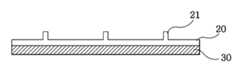
도 3은 본 발명의 일실시예에 따른 발광 키패드용 이엘 디바이스를 도시한 단면도,3 is a cross-sectional view showing an EL device for a light emitting keypad according to an embodiment of the present invention;
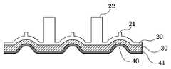
도 4는 본 발명의 또 다른 일실시예에 따른 발광 키패드용 이엘 디바이스를 도시한 단면도,4 is a cross-sectional view showing an EL device for a light emitting keypad according to another embodiment of the present invention;
도 5a 및 5b는 본 발명의 또 다른 일실시예에 따른 발광 키패드용 이엘 디바이스를 도시한 단면도,5A and 5B are cross-sectional views illustrating EL devices for light emitting keypads according to still another embodiment of the present invention;
도 6a 및 6b는 본 발명의 또 다른 일실시예에 따른 발광 키패드용 이엘 디바이스를 도시한 단면도,6A and 6B are cross-sectional views illustrating EL devices for light emitting keypads according to still another embodiment of the present invention;
도 7a 및 7b는 본 발명에 따른 이엘 디바이스 적용한 발광 키패드를 도시한 단면도이다.7A and 7B are cross-sectional views illustrating a light emitting keypad to which an EL device according to the present invention is applied.
** 도면의 주요부호에 대한 설명 **** Description of the main symbols in the drawings **
11: 키판11: keyboard
12: 잉크층12: ink layer
13: 배면층13: back layer
20: 보호층20: protective layer
21: 상부돌기21: upper projection
22: 관통돌기22: through protrusion
30: 이엘 디바이스30: EL device
40: 메탈돔40: metal dome
41: 돔기판41: dome board
42: 접점단자42: contact terminal
43: 인쇄회로기판43: printed circuit board
본 발명은 발광 키패드용 이엘(EL) 디바이스에 관한 것이다.The present invention relates to EL devices for light emitting keypads.
도 1은 일반적인 무선단말기를 도시한 사시도이다.1 is a perspective view showing a general wireless terminal.
휴대 전화기와 같은 무선단말기는 도 1에 도시된 바와 같이 송, 수신 상태 등과 같이 운용에 요구되는 각종 정보를 표시해 주는 액정 화면(120)과 신호발생 및 여러 가지 기능을 수행하기 위한 키패드의 다수의 키 버튼(130)들이 끼워지는 홀을 갖는 키판넬(110)로 구성되어 있다.As shown in FIG. 1, a wireless terminal such as a cellular phone has a
키패드는 숫자 또는 문자 등이 인쇄된 인쇄면이 형성된 다수의 키버튼(130)들을 갖고 있으며, 키버튼(130)은 휴대 전화기의 키판넬(110) 외측으로 돌출된 구조를 갖는다. 사용자는 인쇄면에 표시된 숫자나 문자 등을 확인하여 원하는 키버튼(130)을 눌러 휴대 전화기를 사용하며, 인쇄면을 야간에도 확인할 수 있도록 키버튼(130)의 저면 외측에는 발광소자로 이루어진 광원이 설치되며, 이 광원에서 빛을 조사하면 백라이팅 효과에 의해 키버튼(130)에 인쇄된 숫자나 문자 등을 사용자가 용이하게 인식할 수 있다.The keypad has a plurality of
그러나, 발광 키패드의 광원으로 사용된 기존의 LED 방식의 발광 키패드는 LED 특성상 박형으로의 제작이 불가능하여 키패드가 상대적으로 두껍게 제작된다. 또한, LED 발광에 따른 전력 소모량이 많아서 배터리의 사용시간을 단축시킬 수 있다. 또한, LED의 배치 위치에 따라 발광 균일도가 불균일하여 설계상의 어려움이 따르게 된다. 따라서, 기존의 LED 방식의 발광 키패드의 초박화의 한계 등을 극복하기 위해 EL(Electro Luminescence) 램프 발광 방식(이하,'EL 방식'이라 함)이 적용된 슬림형 발광 키패드의 개발이 요구되고 있다.However, the conventional LED type light emitting keypad used as a light source of the light emitting keypad cannot be manufactured in a thin shape due to the characteristics of the LED, so that the keypad is made relatively thick. In addition, the power consumption according to the LED light emission can be shortened the use time of the battery. In addition, the uniformity of light emission is uneven depending on the arrangement position of the LED, which leads to design difficulties. Accordingly, in order to overcome the limitation of ultra-thinning of the conventional LED type light emitting keypad, there is a demand for the development of a slim type light emitting keypad to which an EL (Electro Luminescence) lamp light emitting method (hereinafter referred to as an 'EL method') is applied.
도 2는 상기의 문제점을 보완하기 위한 종래의 EL 방식 발광 키패드의 단면도로서, 키탑(210), EL 메탈 돔 시트(220) 및 인쇄회로기판(230)으로 구성되며, 상 기 EL 메탈 돔 시트(220)는 EL 시트(221), 메탈 돔(223), 및 베이스 테이프(222)로 구성되어 초박막화, 낮은 소비전력을 실현하게 된다.FIG. 2 is a cross-sectional view of a conventional EL light emitting keypad for supplementing the above problem, and includes a
이러한 EL 방식 메탈 돔 키패드의 기능을 살펴보면, 사용자에 의해 키탑(210)이 눌러지면 키탑(210)의 후면에 위치한 돌기(211)에 의해 메탈 돔(223)과 인쇄회로기판(230)의 고정접점단자(231)가 접촉되어 스위칭되어 작동된다.Looking at the function of the EL-type metal dome keypad, when the
그러나, 상기 종래의 EL 방식 발광 키패드는 돌기(211)에 의해 EL 시트(221)가 지속적으로 가압, 충격되어 EL 시트가 손상, 파손의 위험이 높으며, 따라서 EL의 신뢰성에 큰 문제점을 발생시키고 키패드의 클릭감 저하를 야기시키는 문제점이 있어 이를 해결할 수 있는 EL 디바이스의 구조의 개발이 요구된다.However, in the conventional EL type light emitting keypad, the
본 발명은 상기의 문제점을 해결하기 위한 것으로, 클릭성을 향상시키기 위한 돌기가 상부 방향으로 형성하여, 돌기가 이엘 디바이스를 직접적으로 가압하는 것을 방지하여 이엘 디바이스가 변형, 파손되는 것을 방지할 수 있는 발광 키패드용 이엘 디바이스를 제공하는 것을 목적으로 한다.The present invention is to solve the above problems, a projection for improving the clickability is formed in the upper direction, it is possible to prevent the protrusion of the EL device to directly press the EL device can prevent the EL device from being deformed, broken An object of the present invention is to provide an EL device for a light emitting keypad.
또한, 필요에 따라 관통돌기가 마련되어 이엘 디바이스에서 발산하는 빛이 반사, 간섭되어 음각이 형성되는 것을 방지하고 그대로 광이 투과되도록 할 수 있고, 키판과 이엘 디바이스를 결합하는 것이 보다 용이하게 될 수 있는 발광 키패드 용 이엘 디바이스를 제공하는 것을 목적으로 한다.In addition, through protrusions may be provided as necessary to prevent the light emitted from the EL device from being reflected and interfered, thereby preventing the formation of intaglio, and allowing the light to pass through as it is, and it may be easier to combine the keypad and EL device. An object of the present invention is to provide an EL device for a light-emitting keypad.
상기의 목적을 달성하기 위한 본 발명은,The present invention for achieving the above object,
키판을 구비한 발광 키패드에 사용되는 이엘(EL) 디바이스에 있어서, 상기 이엘 디바이스의 상부에 키의 클릭성을 향상시키기 위해 상부로 돌출된 다수의 상부돌기를 구비한 보호층이 형성된 것을 특징으로 하는 발광 키패드용 이엘 디바이스를 제공한다.An EL device for use in a light-emitting keypad having a keypad, wherein a protective layer is provided on the EL device, the protective layer having a plurality of upper protrusions protruding upward to improve the clickability of the key. An EL device for a light emitting keypad is provided.
또한, 관통홀이 형성된 키판을 구비한 발광 키패드에 사용되는 이엘(EL) 디바이스에 있어서, 상기 이엘 디바이스의 상부에 키의 클릭성을 향상시키기 위해 상부로 돌출된 다수의 상부돌기 및 상기 관통홀에 관통되기 위한 관통돌기를 구비한 보호층이 형성된 것을 특징으로 하는 발광 키패드용 이엘 디바이스를 제공한다.In addition, in an EL device used in a light emitting keypad having a key plate having a through hole formed therein, a plurality of upper protrusions and the through holes protruding upward in order to improve the clickability of a key on the upper part of the EL device. Provided is an EL device for a light emitting keypad characterized in that a protective layer having a through protrusion for penetrating is formed.
또한, 상기 이엘 디바이스 하부에, 다수의 메탈돔이 접합된 것을 특징으로 하는 발광 키패드용 이엘 디바이스를 제공한다.In addition, the EL device provides a EL device for a light emitting keypad, characterized in that a plurality of metal domes are bonded below.
또한, 상기 이엘 디바이스 하부에, 다수의 메탈돔이 일체적으로 형성된 돔기판이 접합된 것을 특징으로 하는 발광 키패드용 이엘 디바이스를 제공한다.In addition, an EL device for a light emitting keypad is provided below the EL device, wherein a dome substrate having a plurality of metal domes integrally formed is bonded thereto.
이하, 도면 및 실시예를 참조하여 본 발명을 보다 상세히 설명한다.Hereinafter, the present invention will be described in more detail with reference to the drawings and examples.
도 3은 본 발명의 일실시예에 따른 발광 키패드용 이엘 디바이스의 단면도이다. 도시된 바와 같이, 키판을 구비한 발광 키패드에 사용되는 이엘(EL) 디바이스에 있어서, 상기 이엘 디바이스(30)의 상부에 키의 클릭성을 향상시키기 위해 상부로 돌출된 다수의 상부돌기(21)를 구비한 보호층(20)이 형성된 것을 특징으로 한다.3 is a cross-sectional view of an EL device for a light emitting keypad according to an embodiment of the present invention. As shown, in the EL device used in the light-emitting keypad provided with the keypad, a plurality of
본 발명에 따른 발광 키패드용 이엘 디바이스는 클릭성을 향상시키기 위한 돌기가 상부 방향으로 형성되어 있어 돌기가 이엘 디바이스를 직접적으로 가압하는 것을 방지하여 이엘 디바이스가 변형, 파손되는 것을 방지하게 된다.EL device for a light emitting keypad according to the present invention is formed with a projection for improving the clickability in the upper direction to prevent the projection directly press the EL device to prevent the EL device from being deformed, broken.
상기 보호층(20) 및 상부돌기(21)는 제한되지 않으나 일체적으로 형성되는 것이 좋으며, 실리콘 재질이 좋다. 상기 보호층은 상부돌기가 직접적으로 이엘 디바이스를 가압하는 것을 완충하는 역할을 할 수 있으며, 또한 상기 이엘 디바이스에 수분, 산소 등이 침투하여 손상되는 것을 방지하는 역할도 할 수 있게 된다.The
상기 상부돌기(21)는 발광 키패드의 키판의 키 위치에 상응하도록 다수 형성되는 것이 좋으며, 사용자에 의해 키가 눌러지게 되면 해당 상부돌기가 가압되어 이에 따라 이엘 디바이스의 하부에 있게 될 돔스위치 등의 스위칭부(도시되지 않음)에서 스위칭이 일어나게 된다.The
상기 EL 디바이스(30)의 구조는 전계를 가하여 무기 또는 유기 발광체가 발광되는 구조라면 제한되지 않고 적용될 수 있고 본 발명에 포함되며, 본 기술분야에서 잘 알려져 있으므로 설명을 생략한다. 일례로 다음과 같은 구성이 적합하다. 즉, EL 디바이스는 절연층, 전면전극층, 발광층, 유전층, 배면전극층, 절연층을 구비하는 것이 좋다. 상기 전면전극층, 발광층, 유전층 및 배면전극층은 상기 EL 디바이스의 발광구조인 EL 시스템을 이룬다. 상기 EL 디바이스(13)는 슬림화를 위해 스크린 프린팅의 방법으로 형성하는 것이 바람직하다.The structure of the
도 4는 본 발명의 또 다른 일실시예에 따른 발광 키패드용 이엘 디바이스의 단면도이다. 도시된 바와 같이, 관통홀이 형성된 키판을 구비한 발광 키패드에 사용되는 이엘(EL) 디바이스에 있어서, 상기 이엘 디바이스(30)의 상부에 키의 클릭성을 향상시키기 위해 상부로 돌출된 다수의 상부돌기(21) 및 상기 관통홀에 관통되기 위한 관통돌기(22)를 구비한 보호층(20)이 형성된 것을 특징으로 한다. 전술한 발광 키패드용 이엘 디바이스와 동일한 구성은 설명을 생략한다.4 is a cross-sectional view of an EL device for a light-emitting keypad according to another embodiment of the present invention. As shown, in an EL device for use in a light emitting keypad having a key plate with a through hole formed therein, a plurality of upper portions protruding upwards to improve the clickability of a key on the upper portion of the
키판에 관통홀을 형성하고(도시되지 않음) 상기 보호층에 관통돌기(22)를 더 구비할 수 있다. 특히, 관통돌기(22)가 각 키의 경계에 해당되도록 형성되는 것이 좋다. 이러한 구성을 통해 특정키를 보다 용이하게 선택적으로 누를 수 있게 되고, 클릭감이 향상되게 된다. 또한, 관통돌기을 형성하여 결합함으로써, 이엘 디바이스에서 발산하는 빛이 반사, 간섭되어 음각이 형성되는 것을 방지하고 그대로 광이 투과되도록 할 수 있다. 또한, 키판과 이엘 디바이스를 결합하는 것이 보다 용이하게 된다.A through hole may be formed in the keypad (not shown), and the protective layer may further include a through
도 5a 및 5b는 본 발명의 또 다른 일실시예에 따른 발광 키패드용 이엘 디바이스의 단면도이다. 도시된 바와 같이, 전술한 이엘 디바이스 하부에, 다수의 메탈돔(40)이 접합된 것을 특징으로 한다.5A and 5B are cross-sectional views of EL devices for light emitting keypads according to another embodiment of the present invention. As shown, a plurality of
즉, 발광 키패드에 있어서, 클릭감과 보다 신뢰성 있는 스위칭을 위해 돔스위치를 도입하게 되는데, 돔스위치는 메탈돔과 그 하부에 형성된 접점단자로 이루어진다. 접점단자는 일반적으로 인쇄회로기판에 형성되게 된다. 상기 메탈돔을 인쇄회로기판에 부착할 수도 있으나, 도시된 바와 같이 이엘 디바이스 하부에 접합시킬 수도 있다. 접합방법은 제한되지 않으나 접착양면테이프 등을 이용하여 간단히 접합시키는 것이 좋다.That is, in the light emitting keypad, a dome switch is introduced for a feeling of click and more reliable switching. The dome switch is formed of a metal dome and a contact terminal formed under the dome switch. Contact terminals are generally formed on a printed circuit board. The metal dome may be attached to the printed circuit board, but may be bonded to the lower portion of the EL device as shown. The bonding method is not limited, but it is better to simply bond using a double-sided tape or the like.
상기 구조의 이엘 디바이스를 발광 키패드 제조시 조립하게 되면 유연성 있는 보호층 및 이엘 디바이스가 도 7a 및 도 7b에 도시된 구조로 변하게 된다.When the EL device having the above structure is assembled during manufacturing of the light emitting keypad, the flexible protective layer and the EL device are changed to the structure shown in FIGS. 7A and 7B.
도 6a 및 6b는 본 발명의 또 다른 일실시예에 따른 발광 키패드용 이엘 디바이스의 단면도이다. 도시된 바와 같이, 전술한 이엘 디바이스 하부에, 다수의 메탈돔(40)이 일체적으로 형성된 돔기판(41)이 접합된 것을 특징으로 한다. 이와 같이 다수의 메탈돔을 일체적으로 형성함으로써 제조를 보다 간단하게 할 수 있게 된다. 상기 돔기판의 하부에는 접점단자가 구비된 인쇄회로기판이 위치하게 된다. 상기 메탈돔은 탄성력이 우수한 재질이 클릭성 향상을 위해 좋다.6A and 6B are cross-sectional views of EL devices for light emitting keypads according to yet another embodiment of the invention. As shown, the
도 7a 및 7b는 본 발명의 일실시예에 따른 이엘 디바이스를 적용한 발광 키패드의 단면도이다. 키판(11), 잉크층(12), 배면층(13, 생략될 수 있다) 등과 그 하부에 형성된 본 발명의 일실시예에 따른 이엘 디바이스와 접점단자가 구비된 인쇄회로기판으로 이루어질 수 있다.7A and 7B are cross-sectional views of a light emitting keypad to which an EL device according to an embodiment of the present invention is applied. A
본 발명을 적용할 경우, 보호층에 형성된 상부돌기가 상부를 향하고 있어, 보호층 하부에 있는 이엘 디바이스가 파손되는 것을 방지할 수 있게 된다.When applying the present invention, the upper protrusion formed on the protective layer is directed upward, it is possible to prevent the EL device under the protective layer from being damaged.
상기의 실시예는 본 발명을 상세히 설명하기 위한 것이고, 본 발명을 한정하기 위함이 아니므로 본 발명의 기술적 사상의 범위내에서 가할 수 있는 변형, 수정, 생략 등은 특허청구범위에 의해 정해지는 본 발명의 권리범위에 포함된다.The above embodiments are intended to describe the present invention in detail, and are not intended to limit the present invention, and thus modifications, modifications, omissions, etc. that can be applied within the scope of the technical idea of the present invention are defined by the claims. It is included in the scope of the invention.
본 발명에 따른 발광 키패드용 이엘 디바이스는 클릭성을 향상시키기 위한 돌기가 상부 방향으로 형성되어 있어 돌기가 이엘 디바이스를 직접적으로 가압하는 것을 방지하여 이엘 디바이스가 변형, 파손되는 것을 방지할 수 있으며, 필요에 따라 관통돌기가 마련되어 이엘 디바이스에서 발산하는 빛이 반사, 간섭되어 음각이 형성되는 것을 방지하고 그대로 광이 투과되도록 할 수 있고, 키판과 이엘 디바이스를 결합하는 것이 보다 용이하게 된다.EL device for a light emitting keypad according to the present invention is a projection for improving the clickability is formed in the upper direction to prevent the projection directly press the EL device can prevent the EL device is deformed, damaged, The through projections are provided to prevent the light emitted from the EL device from being reflected and interfered, thereby preventing the formation of the intaglio and allowing the light to pass through as it is, and it becomes easier to combine the keypad and EL device.
Claims (3)
Translated fromKoreanPriority Applications (1)
| Application Number | Priority Date | Filing Date | Title |
|---|---|---|---|
| KR1020070039575AKR100830542B1 (en) | 2007-04-23 | 2007-04-23 | EL device for light-emitting keypad |
Applications Claiming Priority (1)
| Application Number | Priority Date | Filing Date | Title |
|---|---|---|---|
| KR1020070039575AKR100830542B1 (en) | 2007-04-23 | 2007-04-23 | EL device for light-emitting keypad |
Related Parent Applications (1)
| Application Number | Title | Priority Date | Filing Date |
|---|---|---|---|
| KR1020060053715ADivisionKR100762711B1 (en) | 2006-06-15 | 2006-06-15 | EL device for light-emitting keypad |
Publications (2)
| Publication Number | Publication Date |
|---|---|
| KR20070119489A KR20070119489A (en) | 2007-12-20 |
| KR100830542B1true KR100830542B1 (en) | 2008-05-22 |
Family
ID=39137801
Family Applications (1)
| Application Number | Title | Priority Date | Filing Date |
|---|---|---|---|
| KR1020070039575AExpired - Fee RelatedKR100830542B1 (en) | 2007-04-23 | 2007-04-23 | EL device for light-emitting keypad |
Country Status (1)
| Country | Link |
|---|---|
| KR (1) | KR100830542B1 (en) |
Families Citing this family (1)
| Publication number | Priority date | Publication date | Assignee | Title |
|---|---|---|---|---|
| KR100944722B1 (en)* | 2008-04-16 | 2010-02-26 | (주)미래씨엔피 | Keypad assembly |
Citations (1)
| Publication number | Priority date | Publication date | Assignee | Title |
|---|---|---|---|---|
| KR19980024783U (en)* | 1998-03-26 | 1998-07-25 | 양윤홍 | Communication device |
- 2007
- 2007-04-23KRKR1020070039575Apatent/KR100830542B1/ennot_activeExpired - Fee Related
Patent Citations (1)
| Publication number | Priority date | Publication date | Assignee | Title |
|---|---|---|---|---|
| KR19980024783U (en)* | 1998-03-26 | 1998-07-25 | 양윤홍 | Communication device |
Also Published As
| Publication number | Publication date |
|---|---|
| KR20070119489A (en) | 2007-12-20 |
Similar Documents
| Publication | Publication Date | Title |
|---|---|---|
| US7893375B2 (en) | Non-backlighted illuminating keypad | |
| US6806815B1 (en) | Keypad structure with inverted domes | |
| KR200358531Y1 (en) | EL Metal Dome Keypad | |
| KR20120036076A (en) | Keypad apparatus for portable communication device | |
| KR20070089934A (en) | Thin key unit incorporating thin key sheet and corresponding thin key sheet | |
| JP2012512596A (en) | Light diffusion actuator film (LDAF) keypad module | |
| JP2002343187A (en) | Illuminated pushbutton switch | |
| JP3873156B2 (en) | control panel | |
| KR100880412B1 (en) | EL integrated keypad | |
| KR100705483B1 (en) | Luminous keypad | |
| KR200426230Y1 (en) | Luminous keypad | |
| KR100830542B1 (en) | EL device for light-emitting keypad | |
| KR200325934Y1 (en) | El dome tape key pad | |
| KR100737763B1 (en) | Luminous keypad | |
| JP2007194092A (en) | Membrane sheet and switch device | |
| KR200426232Y1 (en) | EL device for light-emitting keypad | |
| KR100762711B1 (en) | EL device for light-emitting keypad | |
| JP2003067114A (en) | Illumination device | |
| JP2002279849A (en) | Illumination unit and illumination device using the same | |
| KR200426005Y1 (en) | Luminous keypad | |
| KR200426231Y1 (en) | Window-integrated keypad and wireless terminal with same | |
| KR100514759B1 (en) | Super-thin type keypad emitting light | |
| KR101062345B1 (en) | Light emitting side key of mobile communication terminal | |
| WO2007145423A1 (en) | Light emitting keypad | |
| KR100737932B1 (en) | EL lamp sheet and its manufacturing method |
Legal Events
| Date | Code | Title | Description |
|---|---|---|---|
| A107 | Divisional application of patent | ||
| A201 | Request for examination | ||
| PA0107 | Divisional application | St.27 status event code:A-0-1-A10-A16-div-PA0107 St.27 status event code:A-0-1-A10-A18-div-PA0107 | |
| PA0201 | Request for examination | St.27 status event code:A-1-2-D10-D11-exm-PA0201 | |
| P11-X000 | Amendment of application requested | St.27 status event code:A-2-2-P10-P11-nap-X000 | |
| P13-X000 | Application amended | St.27 status event code:A-2-2-P10-P13-nap-X000 | |
| E902 | Notification of reason for refusal | ||
| PE0902 | Notice of grounds for rejection | St.27 status event code:A-1-2-D10-D21-exm-PE0902 | |
| PG1501 | Laying open of application | St.27 status event code:A-1-1-Q10-Q12-nap-PG1501 | |
| E701 | Decision to grant or registration of patent right | ||
| PE0701 | Decision of registration | St.27 status event code:A-1-2-D10-D22-exm-PE0701 | |
| GRNT | Written decision to grant | ||
| PR0701 | Registration of establishment | St.27 status event code:A-2-4-F10-F11-exm-PR0701 | |
| PR1002 | Payment of registration fee | Fee payment year number:1 St.27 status event code:A-2-2-U10-U11-oth-PR1002 | |
| PG1601 | Publication of registration | St.27 status event code:A-4-4-Q10-Q13-nap-PG1601 | |
| PR1001 | Payment of annual fee | Fee payment year number:4 St.27 status event code:A-4-4-U10-U11-oth-PR1001 | |
| PR1001 | Payment of annual fee | Fee payment year number:5 St.27 status event code:A-4-4-U10-U11-oth-PR1001 | |
| FPAY | Annual fee payment | Payment date:20130513 Year of fee payment:6 | |
| PR1001 | Payment of annual fee | Fee payment year number:6 St.27 status event code:A-4-4-U10-U11-oth-PR1001 | |
| PN2301 | Change of applicant | St.27 status event code:A-5-5-R10-R11-asn-PN2301 | |
| PN2301 | Change of applicant | St.27 status event code:A-5-5-R10-R14-asn-PN2301 | |
| P14-X000 | Amendment of ip right document requested | St.27 status event code:A-5-5-P10-P14-nap-X000 | |
| P16-X000 | Ip right document amended | St.27 status event code:A-5-5-P10-P16-nap-X000 | |
| Q16-X000 | A copy of ip right certificate issued | St.27 status event code:A-4-4-Q10-Q16-nap-X000 | |
| FPAY | Annual fee payment | Payment date:20140513 Year of fee payment:7 | |
| PR1001 | Payment of annual fee | Fee payment year number:7 St.27 status event code:A-4-4-U10-U11-oth-PR1001 | |
| LAPS | Lapse due to unpaid annual fee | ||
| PC1903 | Unpaid annual fee | Not in force date:20150514 Payment event data comment text:Termination Category : DEFAULT_OF_REGISTRATION_FEE St.27 status event code:A-4-4-U10-U13-oth-PC1903 | |
| PC1903 | Unpaid annual fee | Ip right cessation event data comment text:Termination Category : DEFAULT_OF_REGISTRATION_FEE Not in force date:20150514 St.27 status event code:N-4-6-H10-H13-oth-PC1903 | |
| P22-X000 | Classification modified | St.27 status event code:A-4-4-P10-P22-nap-X000 | |
| R18-X000 | Changes to party contact information recorded | St.27 status event code:A-5-5-R10-R18-oth-X000 | |
| R18-X000 | Changes to party contact information recorded | St.27 status event code:A-5-5-R10-R18-oth-X000 |