KR100827826B1 - Link type cap and manufacturing method - Google Patents
Link type cap and manufacturing methodDownload PDFInfo
- Publication number
- KR100827826B1 KR100827826B1KR1020060083723AKR20060083723AKR100827826B1KR 100827826 B1KR100827826 B1KR 100827826B1KR 1020060083723 AKR1020060083723 AKR 1020060083723AKR 20060083723 AKR20060083723 AKR 20060083723AKR 100827826 B1KR100827826 B1KR 100827826B1
- Authority
- KR
- South Korea
- Prior art keywords
- cap
- taka
- manufacturing
- forming
- staple
- Prior art date
- Legal status (The legal status is an assumption and is not a legal conclusion. Google has not performed a legal analysis and makes no representation as to the accuracy of the status listed.)
- Active
Links
- 238000004519manufacturing processMethods0.000titleclaimsabstractdescription34
- 238000000034methodMethods0.000claimsabstractdescription22
- 239000002994raw materialSubstances0.000claimsabstractdescription5
- 238000004080punchingMethods0.000claimsabstractdescription4
- 238000001125extrusionMethods0.000claimsabstractdescription3
- 239000002023woodSubstances0.000abstractdescription8
- 238000004806packaging method and processMethods0.000abstractdescription7
- 238000001746injection mouldingMethods0.000description7
- 230000008569processEffects0.000description5
- 238000000465mouldingMethods0.000description4
- 238000005520cutting processMethods0.000description3
- 238000010586diagramMethods0.000description3
- 238000003860storageMethods0.000description3
- 239000000853adhesiveSubstances0.000description2
- 230000001070adhesive effectEffects0.000description2
- 238000005452bendingMethods0.000description2
- 230000008859changeEffects0.000description2
- 230000003796beautyEffects0.000description1
- 230000008901benefitEffects0.000description1
- 230000015572biosynthetic processEffects0.000description1
- 230000008878couplingEffects0.000description1
- 238000010168coupling processMethods0.000description1
- 238000005859coupling reactionMethods0.000description1
- 230000000694effectsEffects0.000description1
- 239000003292glueSubstances0.000description1
- 239000000463materialSubstances0.000description1
- 230000013011matingEffects0.000description1
- 238000012986modificationMethods0.000description1
- 230000004048modificationEffects0.000description1
- 230000002265preventionEffects0.000description1
Images


Classifications
- B—PERFORMING OPERATIONS; TRANSPORTING
- B25—HAND TOOLS; PORTABLE POWER-DRIVEN TOOLS; MANIPULATORS
- B25C—HAND-HELD NAILING OR STAPLING TOOLS; MANUALLY OPERATED PORTABLE STAPLING TOOLS
- B25C5/00—Manually operated portable stapling tools; Hand-held power-operated stapling tools; Staple feeding devices therefor
- F—MECHANICAL ENGINEERING; LIGHTING; HEATING; WEAPONS; BLASTING
- F16—ENGINEERING ELEMENTS AND UNITS; GENERAL MEASURES FOR PRODUCING AND MAINTAINING EFFECTIVE FUNCTIONING OF MACHINES OR INSTALLATIONS; THERMAL INSULATION IN GENERAL
- F16B—DEVICES FOR FASTENING OR SECURING CONSTRUCTIONAL ELEMENTS OR MACHINE PARTS TOGETHER, e.g. NAILS, BOLTS, CIRCLIPS, CLAMPS, CLIPS OR WEDGES; JOINTS OR JOINTING
- F16B15/00—Nails; Staples
- F16B15/0015—Staples
Landscapes
- Engineering & Computer Science (AREA)
- Mechanical Engineering (AREA)
- General Engineering & Computer Science (AREA)
- Closures For Containers (AREA)
- Lining Or Joining Of Plastics Or The Like (AREA)
Abstract
Translated fromKoreanDescription
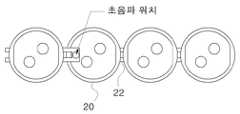
Translated fromKorean도 1 은 종래의 연결형 타카용 캡 제조 방법 중 초음파를 이용하여 타카용 캡을 연결하는 방법에 대한 도면을,1 is a view of a method for connecting a cap for the Taka using ultrasonic waves of the conventional manufacturing method for a connected Taka cap,
도 2는 본 발명의 일 실시예에 따른 연결형 타카용 캡이 타카에 장착되는 모습을 나타내는 정면도를,Figure 2 is a front view showing a state in which the cap for the connection type Taka according to an embodiment of the present invention is mounted on the Taka,
도 3은 본 발명의 일 실시예에 따른 연결형 타카용 캡이 스테플에 의해 결합되는 모습을 나타내는 개략도를,Figure 3 is a schematic diagram showing a state that the cap for the linked Taka according to an embodiment of the present invention is coupled by a staple,
도 4는 본 발명의 일 실시예에 따른 연결형 타카용 캡 제조방법에 관한 대략적인 순서도를,Figure 4 is a schematic flow chart related to the cap manufacturing method for the linked Taka according to an embodiment of the present invention,
도 5는 본 발명의 일 실시예에 따른 연결형 타카용 캡의 형상을 나타내는 도면을,5 is a view showing the shape of the cap for the linked Taka according to an embodiment of the present invention,
도 6은 본 발명의 일 실시예에 따른 연결형 타카용 캡의 제작 평면도를,6 is a plan view of manufacturing a cap for a connection type Taka according to an embodiment of the present invention,
도 7은 본 발명의 일 실시예에 따른 연결형 타카용 캡 제작에 있어서의 칼집처리를 하는 단면도를,7 is a cross-sectional view of the sheath treatment in the manufacture of a cap for a connection type Taka according to an embodiment of the present invention,
도 8은 본 발명의 일 실시예에 따른 연결형 타카용 캡의 형상의 단면도를 각 나타낸다.Figure 8 shows a cross-sectional view of the shape of the cap for the connection type Taka according to an embodiment of the present invention.
* 도면의 주요부분에 대한 부호의 설명 *Explanation of symbols on the main parts of the drawings
10 : 타카11 : 스테플 이송장치10: Taka 11: staple transfer device
12 : 방아쇠13 : 스테플12: trigger 13: staple
20 : 타카용 캡21 : 캡 이송장치20: cap for taka 21: cap feeder
22 : 연결부(브리지)30 : 판 시트22: connection portion (bridge) 30: plate sheet
31 : 이송스토퍼32 : 가이드 핀31: transfer stopper 32: guide pin
33 : 프레스33: Press
본 발명은 목재상자 포장시 또는 방수지 등을 목재 등에 고정시 사용되는 캡 타카의 연결형 타카용 캡 및 그 제조방법에 관한 발명이다. 상기 연결형 타카용 캡은 스테플과 결합하여 목재 등에 방수지 등을 연속적으로 고정시키기 위해 사용되는 것을 말한다.The present invention relates to a cap for a linked Taka cap and a method of manufacturing the cap used for packaging a wooden box or fixing the waterproof paper and the like. The connected Taka cap is used to combine a staple and to secure a waterproof paper, such as wood continuously.
종래에는 타카용 캡을 제작하기 위해서는 한 개씩 와셔형상으로 사출성형하여 제조하는 방법이 사용되었다. 이 방법에 의할 시 타카용 캡 제조에 많은 시간이 소요될 뿐만 아니라 스테플링(또는 네일링) 작업시 한개씩 손으로 잡고 못으로 고정을 시키다 보니 연속적으로 작업이 이루어지지 않는 문제점이 있었다.In the related art, in order to manufacture a cap for taka, a method of manufacturing by injection molding into a washer shape was used one by one. According to this method, not only takes a lot of time to manufacture the cap for Taka, but also stapling (or nailing) when working with one by one holding the nail fixed by the problem did not work continuously.
또한, 종래에는 연속적인 스테플링 작업을 위해 25개씩 타카용 캡이 연결된 띠를 사출성형의 방법으로 제조한 다음 상기 연결띠를 초음파를 이용하여 연결시키는 방법으로 제조되었다.In addition, in the prior art, for each continuous stapling operation, the bands for each of the Taka caps were connected to each other by the injection molding method, and then the connection bands were manufactured by the method of using ultrasonic waves.
도 1 은 종래의 타카용 캡 제조 방법 중 초음파를 이용하여 타카용 캡을 연결하는 방법에 대한 도면을 나타낸다.1 is a view showing a method of connecting a cap for the Taka using ultrasonic waves of the conventional manufacturing method for the cap for Taka.
동 도면에서 보는 바와 같이 연속적인 스테플링 작업을 위해 사출성형의 방법으로 복수개의 타카용 캡(20)으로 구성된 연결 띠를 생산한 다음, 상기 방법으로 생산된 띠를 다시 복수개 연결시켜 사용하였으며 상기 연결방법은 초음파를 이용하여 연결시키는 방법으로 제조되었다. 상기와 같이 복수개의 연결띠를 다시 초음파를 이용하여 연결하는 이유는 통상 스테플의 수가 생산된 연결 띠의 수보다 많을 뿐만 아니라 스테플 작업이 보통 빠른 시간 내에 많은 스테플링이 이루어지기 때문이다. 통상 스테플의 수는 200개이고, 캡 저장공간에 들어갈 수 있는 타카용 캡의 수도 그와 비슷하기 때문에 통상 200여개의 캡이 연결되어 제조된다.As shown in the figure, for continuous stapling work was produced by the injection molding method of a plurality of caps for the
사출성형의 특성상 수백 개의 연결된 타카용 캡을 제조할 수는 없어 부득이 연결 띠를 서로 연결시켜 사용하여야 한다.Due to the nature of injection molding, it is not possible to manufacture hundreds of connected taka caps.
동 도면은 첫 번째 연결 띠의 마지막 타카용 캡과 두 번째 연결 띠의 첫 번째 캡을 초음파를 이용하여 연결하는 작업을 나타내며, 이 방법에 의하여 스테플링 작업시 초음파로 연결된 부위(22)가 통상의 연결부위(22)보다 약하게 연결되어 작업 전에 미리 끊어지거나 혹은 너무 강하게 연결되어 스테플 작업과 동시에 끊어져야 할 시점에 끊어지지 않게 되어 작업 효율이 낮아지는 문제점이 있다.The figure shows an operation of connecting the last taka cap of the first connecting strip and the first cap of the second connecting strip by using ultrasonic waves. There is a problem that the connection efficiency is lowered than the
그리고 타카용 캡의 형상이 아무런 굴곡이나 형상의 변화가 없는 통상의 낮은 원기둥의 형태로 구성되어 스테플과 결합하여 목재 등에 체결시 스테플이 목재에 강력하게 결합됨으로써 타카용 캡이 스테플의 저항력을 받아 캡의 가장자리 부분이 들리게 되어 캡 전체가 목재 등에 부착되지 못하여 부착력이 떨어지고 외관상 미려하지 못한 문제점이 있었다.And the shape of the cap for Taka is formed in the form of a normal low cylinder without any bending or change in shape, and when combined with staples when stapling is strongly coupled to the wood, the cap for Taka is staple resistance There was a problem that the edge of the cap is heard to receive the cap is not attached to the entire wood, such that the adhesive strength is reduced and the appearance is not beautiful.
본 발명은 상기와 같은 문제점을 해결하기 위해 안출된 것으로서, 본 발명의 목적은 연속적인 스테플링 작업시 작업 전에 타카용 캡이 미리 끊어져 버려서 연속작업이 이루어지지 않거나 스테플링 작업시 끊어져야 할 적시에 끊어지지 않아서 생길 수 있는 단속적인 작업을 미연에 방지할 수 있는 연결형 타카용 캡을 제조하는 방법을 제공하는 데 있다.The present invention has been made to solve the above problems, the object of the present invention is that the cap for the Taka is broken in advance before the work during the continuous stapling work in a timely manner that is not done or broken during the stapling work The present invention provides a method of manufacturing a cap for a connected taka that can prevent uninterrupted work that may occur without breaking.
또한, 타카용 캡의 형상의 윗면 중 스테플링 되는 가운데 일부의 두께를 얇게 성형하거나 혹은 윗면의 표면보다 낮게 성형함으로써 스테플링시 나타날 수 있는 가장자리 부분이 들려 비틀어지는 현상을 제거하는 타카용 캡을 제공하는 데 있다.In addition, by forming a thin part of the thickness of the stapling of the upper surface of the shape of the cap for Taka or lower than the surface of the upper surface to provide a cap for Taka to remove the phenomenon that the edge portion that may appear when stapling is lifted There is.
상기 목적을 달성하기 위한 원재료 믹싱작업, 판시트 압출작업, 판시트 가공작업으로 이루어지는 연결형 타카용 캡 제조방법에 있어서,In the manufacturing method of the cap for connection type Taka made of a raw material mixing operation, plate sheet extrusion operation, plate sheet processing operation to achieve the above object,
상기 판시트 가공작업은, 캡간 연결부위가 작업간 원활히 떨어지도록 하는 칼집성형단계; 캡간 연결부위의 꼬임을 방지하기 위한 복수개의 연결부를 형성하기 위한 펀칭단계; 캡의 외형을 형성하기 위한 외부제거단계; 을 포함하여 이루어지는 것이 가능하다.The sheet sheet processing operation, the sheath forming step to ensure that the connection between the cap smoothly falling between operations; A punching step for forming a plurality of connecting portions for preventing the twist between the caps; External removal step for forming the outer shape of the cap; It is possible to include made.
또한, 상기 판시트 가공작업은, 캡의 가장자리가 하부로 향하도록 굴곡을 형성하는 포밍단계를 더 포함할 수도 있으며, 상기 포밍단계는 스테플이 통과되는 캡의 중앙부위가 주변보다 낮게 형성되거나 캡의 중앙부위가 주변보다 얇게 형성되도록 하는 제조방법이 가능하다.In addition, the sheet sheet processing operation may further include a forming step of forming a curvature so that the edge of the cap toward the bottom, wherein the forming step is formed in the center portion of the cap through which the staple passes lower than the periphery or the cap It is possible to manufacture a method so that the central portion of the thinner than the surroundings.
상기 목적을 달성하기 위한 타카에 장착되는 연결형 타카용 캡에 있어서,In the cap for connection type Taka attached to the Taka for achieving the above object,
상기 타카용 캡은 복수개가 서로 이어져 구성되며, 상기 이어지는 부분은 비틀림 방지를 위해 2 이상의 연결고리가 형성되되 상기 연결고리에는 스테플링 작업시 원활한 끊김을 위한 홈이 형성된 것을 특징으로 하여 이루어지거나, 캡의 가장자리가 하부를 향하도록 굴곡이 형성되어 있는 것이 가능하다.The cap for the Taka is composed of a plurality of connected to each other, the subsequent portion is formed with two or more connecting rings to prevent twisting, the connecting ring is made, characterized in that the groove is formed for smooth disconnection during the stapling operation, or the cap It is possible that the bend is formed so that the edge of the lower side.
또한, 상기 타카용 캡은 스테플이 통과되는 캡의 중앙부위는 주변보다 낮게 형성되거나, 주변보다 얇게 형성되는 타카용 캡인 것이 가능하다.In addition, the cap for the Taka may be a cap for the Taka is formed lower than the center portion of the cap through which staples pass, or thinner than the periphery.
이하, 첨부된 도면을 참조하여 본 발명에 따른 타카용 캡 및 그 제조방법을 상세히 설명한다.Hereinafter, with reference to the accompanying drawings will be described in detail for the cap for Taka and its manufacturing method according to the present invention.
도 2는 본 발명의 일 실시예에 따른 연결형 타카용 캡 제조방법에 관한 것으 로서 타카용 캡이 타카에 장착되는 모습을 나타내는 정면도이다.2 is a front view showing a state in which the cap for the Taka is mounted on the Taka as a method for manufacturing a cap for a connection type Taka according to an embodiment of the present invention.
동 도면에서 보는 바와 같이 캡 타카(10)에는 스테플 이송장치(11), 타카용 캡(20), 캡 이송장치(21) 및 방아쇠(12) 등 스테플링 작업을 필요로 하는 기타의 구성요소를 포함하여 구성된다.As shown in the figure, the
타카용 캡(20)은 복수개를 붙인 상태로 제조되어야 하며 롤의 형태로 말아서 타카(10)의 내부에 장착되어 사용되되, 작업시에는 스테플(13)과 결합하여 목재 등의 포장 등에 사용되며 결합시의 스테플(13)의 충격으로 인해 타카용 캡 연결부(22)가 하나씩 끊어지면서 고정되게 된다.The
타카용 캡(20)의 이송은 캡 이송장치(21)에 의해 하나씩 앞으로 이동되는데 가장 마지막의 타카용 캡(20)은 이송장치(21)에 의해서 이송되지 않기 때문에 통상 연결된 타카용 캡(20)의 숫자는 스테플(13)의 숫자보다 하나 많은 201개가 제조된다.The feed of the
도 3은 본 발명의 일 실시예에 따른 연결형 타카용 캡이 스테플에 의해 결합되는 모습을 나타내는 개략도이다.Figure 3 is a schematic diagram showing a state in which the cap for the connected taka according to an embodiment of the present invention is coupled by a staple.
스테플(13)은 ㄷ자 형상의 모양을 하고 있으며 상기 스테플(13)은 복수개가 연결된 상태에서 스테플 이송장치(11)에 실장된다. 타카(10)의 방아쇠(12)가 한번 당겨질 때마다 타카용 캡(20)의 중앙부위에 스테플(13)이 관통하여 목재 등에 결합되는데 결합 후의 모습은 도면상의 아랫부분에 나타나 있다.The
상기와 같이 스테플(13)에 타카용 캡(20)을 씌위서 스테플링을 하는 이유는 스테플(13)에 의한 포장품의 직접적인 훼손을 방지하기 위함이며 또한 오랫동안 포장시 스테플(13) 자체의 날카로움으로 인해 포장품이 손실되는 것을 방지하기 위함이다.The reason for stapling the
도 4는 본 발명의 일 실시예에 따른 연결형 타카용 캡 제조방법에 관한 대략적인 순서도를 나타낸다.Figure 4 shows a schematic flow diagram for a cap manufacturing method for a linked taka according to an embodiment of the present invention.
종래에는 타카용 캡 연결 띠 제조시 사출성형의 방법이 사용되었으나, 앞에서도 살펴본 바와 같이 사출성형의 방법으로는 스테플 수만큼의 연결 띠를 제조할 수 없으며 부득이 연결 띠간 부착을 위해 초음파를 이용한 방법이 사용되었다.Conventionally, injection molding was used to manufacture a cap connection strip for taka, but as described above, the injection molding method cannot produce as many staples as the number of staples, and inevitably uses ultrasonic waves to attach the connection strips. This was used.
도면에서 보는 바와 같이 타카용 캡 제조의 원료가 되는 플라스틱 제조의 원재료를 믹싱하여 압출기에 넣어 타카용 캡을 만들 수 있는 적당한 두께, 폭 및 길이를 갖는 판 시트를 성형한다. 상기 판 시트는 타카용 캡 모양의 프레스로 압력을 가해 필요없는 부분이 떨어져 나올 수 있도록 그 폭은 캡의 지름보다 약간 커야하며 길이는 제작코자 하는 캡의 연결띠의 길이보다 약간 긴 정도로 제작되어야 한다.As shown in the drawing, the raw material of plastic production, which is a raw material for cap production for taka, is mixed and put into an extruder to form a sheet sheet having a suitable thickness, width and length to make a cap for taka. The sheet should be made of a cap-shaped press for pressure, so that its width should be slightly larger than the diameter of the cap and the length should be slightly longer than the length of the connecting strip of the cap to be produced. .
그리고 판 시트가 프레스 금형에 넣어진 상태에서 프레스를 이용하여 연결 부 형상을 펀치로 따내어 성형하고, 상기 연결부를 절단칼집 펀치를 이용하여 완전히 절단하지 않고 약간만 칼집을 내게 된다. 이는 연결형 타카용 캡을 이동시에나 포장시에는 쉽게 끊어지지 않을 정도이나, 타카에 장착 후 작업시에는 쉽게 끊어질 정도로 적절한 깊이만큼의 칼집을 성형하여야 한다.Then, in the state where the sheet sheet is put into the press die, the shape of the connection part is punched out using a press and molded, and the cutting part is cut slightly without cutting completely using the cutting knife punch. It is necessary to form a sheath of a suitable depth so that the cap for the linked type is not easily broken when moving or packaging, but easily broken when mounted on the taka.
이때 연결부는 포장간 꼬임 방지를 위해 복수개의 연결부 형태로 성형하는 것이 가능하다. 이렇게 성형된 타카용 캡을 롤의 형태로 말아서 포장하면 캡 타카에 바로 넣어 사용할 수 있게 된다.In this case, the connection part may be molded into a plurality of connection parts to prevent twisting between packages. The molded cap for Taka is rolled up in the form of a roll to be packaged and used directly in the cap taka.
도 5는 본 발명의 일 실시예에 따른 연결형 타카용 캡 제조방법에 관한 캡의 형상을 나타내는 도면이다.5 is a view showing the shape of the cap of the cap manufacturing method for a linked Taka according to an embodiment of the present invention.
동 도면에서 보는 바와 같이 도 4에서의 방법에 의해서 제작된 타카용 캡(20)을 롤의 형태로 말아서 타카의 캡 저장위치에 저장되며 캡의 첫부분을 저장위치의 상부로부터 이탈시켜 캡 이송위치로 이송시키게 된다. 그렇게 되면 연결된 캡이 이송위치에 순차적으로 이송되어 연속작업이 이루어지게 된다.As shown in the figure, the
캡(20)의 형태는 둥근 모양의 캡이 사용되는 것이 가능하며 그 두께는 스테플이 관통될 수 있으면서도 기름종이 등을 지지할 수 있는 형태의 것이어야 한다.The shape of the
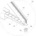
도 6은 본 발명의 일 실시예에 따른 연결형 타카용 캡의 제작 평면도를 나타낸다.Figure 6 shows a manufacturing plan of the cap for the linked Taka according to an embodiment of the present invention.
동 도면에서 보는 바와 같이 판시트(30)가 좌측에서 우측으로 이동하면서 작업이 진행되는데 먼저 판시트(30)가 작업위치상에 위 혹은 아래로 치우치지 아니하도록 가이드 핀(32)에 의해 상하의 위치가 고정되게 된다.As shown in the figure, the work proceeds while the
그리고 이송스토퍼(31)에 의해 작업간격이 조절되어 캡(20)과 캡(20)간의 중복작업이나 누락작업이 생기지 않도록 한다. 즉, 이송스토퍼(31)에 의해 각 캡(20) 에 정해진 작업이 수행될 수 있도록 정확한 간격으로 이동시켜 줄 수 있다.And the working interval is adjusted by the
타카용 캡(20)의 제작은 연결부(22)에 칼집을 성형하는 칼집성형단계, 연결부(20)의 생성 및 연결부의 형상을 2브릿지의 형태로 하기위한 펀칭단계 및 캡(20)의 외형을 만들기 위한 외부제거단계로 구성된다.The production of the
또한, 상기 작업에 타카용 캡(20)의 형태를 가장자리 부분과 중앙부분이 낮고 가장자리와 중앙부분을 제외한 부분은 높게 형성되도록 하는 등 굴곡 형성 및 두께 조정을 위한 포밍단계를 포함하여 구성되는 것이 가능하다.In addition, the shape of the
먼저, 이송스토퍼(31)에 이송된 첫 번째 공정은 캡(20)과 캡(20)간의 연결부(22)에 칼집성형작업이 이루어진다. 그 다음 공정으로 이송된 판 시트(30)는 캡 연결부(22)를 2브리지로 만들기 위한 펀치작업이 수행된다. 그리고 캡(20)의 외부형상을 제외한 나머지 부분을 제거하는 외부제거작업이 수행된다. 상기 첫 번째 공정과 두 번째 공정 사이에 캡(20)이 목재 등에 잘 부착되도록 캡(20)의 형상을 성형하는 포밍작업이 추가적으로 진행될 수 있다. 여기서의 포밍작업이란, 캡(20)이 바닥에 잘 부착되도록 캡(20)의 중앙부위의 높이를 낮게 하거나 캡(20)의 가장자리의 형상에 굴곡을 주는 등 도 8의 경우에서 설명하는 형태의 것으로 하는 추가작업을 말한다.First, the first process transferred to the
한편, 상기 작업방법의 순서는 발명의 요지를 변경하지 아니하는 범위내에서 순서를 변경하는 것 또한 가능하다.On the other hand, the order of the working method is also possible to change the order within the scope not changing the gist of the invention.
도 7은 본 발명의 일 실시예에 따른 연결형 타카용 캡 제작에 있어서의 칼집 처리를 하는 단면도를 나타낸다.7 is a cross-sectional view of the sheath treatment in the production of a cap for a connection type Taka according to an embodiment of the present invention.
칼집처리는 타카용 캡(20)과 캡의 연결부(22)에 칼집처리 기능을 갖는 프레스(33)에 의해 이루어지게 되는데 스테플 작업시에 연결부가 원활하게 끊길 만큼 성형이 가능하다면 칼집처리가 필요 없겠지만, 통상 캡(20)의 두께와 동일한 두께의 연결부로는 원활한 스테플링 작업이 되지 않으므로 원활한 작업을 위해 칼집처리 작업이 필요하게 된다.Sheath treatment is made by a press 33 having a sheath treatment function on the
도 8은 본 발명의 일 실시예에 따른 타카용 캡의 형상의 단면도를 나타낸다.Figure 8 shows a cross-sectional view of the shape of the cap for the Taka according to an embodiment of the present invention.
동 도면에서 보는 바와 같이 캡(20)의 형상은 낮은 원기둥의 형태가 아니고 중앙부위가 가장자리부위보다 솟은 형태, 즉 캡(20)의 가장자리 부분이 아래방향으로 굴곡된 형태의 캡의 형상이 사용된다(그림 A). 이는 라운드 캡이 목재 등에 부착시 가장자리 부분이 가운데 스테플의 압력에 의한 영향으로 위로 들리는 것을 방지하기 위함이다.As shown in the figure, the shape of the
또한 캡의 형상을 내측면을 둥근 형태의 것이 아니라 내각을 주어 들림의 효과를 줄이도록 성형하는 방법(그림 B)과 위측의 두께를 가장자리부분의 두께보다 얇게 성형하여 스테플의 충격을 완화하게 하여 성형하는 것이 가능하다(그림 C).In addition, the shape of the cap is not round but the inner side is molded to reduce the effect of lifting (Fig. B) and the thickness of the upper side is made thinner than the thickness of the edge to mitigate the impact of the staples. It is possible to mold (Figure C).
그리고 윗면 형상에 단차를 주어 스테플링시 외측면이 들리는 저항력을 감소케하는 것이 가능하며(그림 D) 상기 단차를 타카용 캡의 가장자리와 동일한 평면상에 위치시킴으로서 스테플링시 타카용 캡 내부가 목재 등에 직접 닿은 상태에서 작업이 이루어지게 되어 저항력이 거의 발생하지 않도록 하는 것 또한 가능하다(그림 E).In addition, it is possible to reduce the resistance to lift the outer surface when stapling by giving a step to the top shape (Fig. D) by placing the step on the same plane as the edge of the cap for takake, It is also possible that the work is done in direct contact with the back, so that little resistance is generated (Fig. E).
이상에서 설명한 것은 본 발명에 따른 연결형 타카용 캡 및 그 제조방법의 일 실시예에 불과한 것으로, 본 발명은 상기한 실시예에 한정되지 않고, 이하의 특허청구범위에서 청구하는 바와 같이 본 발명의 요지를 벗어남이 없이 당해 발명이 속하는 분야에서 통상의 지식을 가진 자라면 누구든지 다양한 변경 실시가 가능한 범위까지 본 발명의 기술적 사상이 있다고 할 것이다.What has been described above is only one embodiment of the cap for connection type Taka according to the present invention and a manufacturing method thereof, and the present invention is not limited to the above-described embodiment, as claimed in the following claims the gist of the present invention Without departing from the scope of the present invention to those of ordinary skill in the art to which a variety of modifications can be made to the spirit of the present invention.
상기와 같이 본 발명에 따르게 되면 사출성형의 방법으로 캡을 제조하는 것 보다 캡과 캡을 연결하는 초음파 등을 이용한 연결작업이 필요없게 됨으로써 시간과 인력면에 있어 획기적인 절감의 효과를 기대할 수 있게 된다.According to the present invention as described above it is possible to expect a significant savings in time and manpower surface by eliminating the need for the connection work using ultrasonic waves connecting the cap and the cap than manufacturing the cap by the injection molding method. .
또한, 연속적인 스테플링 작업에 있어서 캡과 캡을 연결하는 방법에 의한 경우보다 작업전 캡간 끊김이 없고 작업후 잘 끊어지게 되는 캡을 제작할 수 있어 타카작업이 연속적으로 이루어질 수 있다는 장점이 있다.In addition, in the continuous stapling operation, there is no break between the caps before the operation, and the cap can be well cut after the operation than the case by the method of connecting the cap has the advantage that the Taka work can be made continuously.
그리고 캡의 형상을 부착하고자 하는 재료에 견고하게 부착되도록 캡을 성형함으로써 비틀림의 방지로 인한 부착력의 향상, 부착력이 향상됨으로써 포장 등에 있어서 내구성의 증대 및 외관상의 미려함을 추가적으로 가질 수 있다.And by molding the cap so as to be firmly attached to the material to be attached to the shape of the cap to improve the adhesion force due to the prevention of torsion, the adhesive force is improved, it is possible to further increase the durability in packaging and appearance and the beauty of appearance.
Claims (8)
Translated fromKoreanPriority Applications (1)
| Application Number | Priority Date | Filing Date | Title |
|---|---|---|---|
| KR1020060083723AKR100827826B1 (en) | 2006-08-31 | 2006-08-31 | Link type cap and manufacturing method |
Applications Claiming Priority (1)
| Application Number | Priority Date | Filing Date | Title |
|---|---|---|---|
| KR1020060083723AKR100827826B1 (en) | 2006-08-31 | 2006-08-31 | Link type cap and manufacturing method |
Publications (2)
| Publication Number | Publication Date |
|---|---|
| KR20080020339A KR20080020339A (en) | 2008-03-05 |
| KR100827826B1true KR100827826B1 (en) | 2008-05-07 |
Family
ID=39395379
Family Applications (1)
| Application Number | Title | Priority Date | Filing Date |
|---|---|---|---|
| KR1020060083723AActiveKR100827826B1 (en) | 2006-08-31 | 2006-08-31 | Link type cap and manufacturing method |
Country Status (1)
| Country | Link |
|---|---|
| KR (1) | KR100827826B1 (en) |
Citations (5)
| Publication number | Priority date | Publication date | Assignee | Title |
|---|---|---|---|---|
| JPH07190027A (en)* | 1993-08-09 | 1995-07-28 | Murata Sangyo Kk | Connected nail |
| JPH0960628A (en)* | 1995-08-22 | 1997-03-04 | Masatoshi Ouchi | Screw nail retaining belt |
| JP2001037763A (en) | 1999-06-30 | 2001-02-13 | Ethicon Inc | Foaming material for staple application device |
| JP2002130232A (en) | 2000-10-20 | 2002-05-09 | Hinomoto Shokai:Kk | Wiring staple |
| JP2006194379A (en)* | 2005-01-14 | 2006-07-27 | Jpf Works Kk | Connecting pin |
- 2006
- 2006-08-31KRKR1020060083723Apatent/KR100827826B1/enactiveActive
Patent Citations (5)
| Publication number | Priority date | Publication date | Assignee | Title |
|---|---|---|---|---|
| JPH07190027A (en)* | 1993-08-09 | 1995-07-28 | Murata Sangyo Kk | Connected nail |
| JPH0960628A (en)* | 1995-08-22 | 1997-03-04 | Masatoshi Ouchi | Screw nail retaining belt |
| JP2001037763A (en) | 1999-06-30 | 2001-02-13 | Ethicon Inc | Foaming material for staple application device |
| JP2002130232A (en) | 2000-10-20 | 2002-05-09 | Hinomoto Shokai:Kk | Wiring staple |
| JP2006194379A (en)* | 2005-01-14 | 2006-07-27 | Jpf Works Kk | Connecting pin |
Also Published As
| Publication number | Publication date |
|---|---|
| KR20080020339A (en) | 2008-03-05 |
Similar Documents
| Publication | Publication Date | Title |
|---|---|---|
| US4026413A (en) | Plastics strips | |
| US2712169A (en) | Machine for severing a ribbon of plasterboard to form plasterboard panels and finishing the ends of the panels | |
| CN101041247A (en) | Wooden container | |
| US8835017B2 (en) | Metal sheet member having high plastic bonding strength | |
| KR100827826B1 (en) | Link type cap and manufacturing method | |
| TW201518176A (en) | Automatic packaging shaping machine | |
| CN205704490U (en) | Zigzag mode cutting knife for corrugated paper processing | |
| KR101653123B1 (en) | Lighting gat and Note cover of Korean paper and how to make it | |
| EP3210894B1 (en) | Split lower cutters for buckle-free steel belt strapping tool | |
| CN208853575U (en) | A kind of stamping equipment of automatic material receiving | |
| CN208438753U (en) | Cigarette PE heat shrink films production equipment | |
| KR101288773B1 (en) | Vinyl wrapper having a plurality of storage and method of manufacturing the same | |
| CN205599748U (en) | Prevent jumping sweeps device | |
| CN212216795U (en) | Continuous die for producing metal parts | |
| KR102417085B1 (en) | Packaging paper case containing a plurality of papers partially overlapped and method for preparing the same | |
| JP2010052905A (en) | Cap for roll, method of manufacturing the same, and frame for conveying roll | |
| CN208960776U (en) | An automatic progressive die for punching, budding and blanking of brake shoe linings | |
| CN104290355A (en) | Crease line pressing tool for packaging box and crease line structure of packaging box | |
| CN116770643B (en) | Corrugated board and corrugated board packing box thereof | |
| CN207088035U (en) | A kind of corrugated board cutting mould | |
| CA2445228A1 (en) | Blank support device | |
| KR100641336B1 (en) | Knife Mold for Press | |
| CN111570624A (en) | Production process of metal parts and continuous die thereof | |
| CN213321973U (en) | Paper container processing equipment | |
| CN220177960U (en) | Mould structure for preventing narrow material product workpiece of automobile mould from being damaged easily |
Legal Events
| Date | Code | Title | Description |
|---|---|---|---|
| A201 | Request for examination | ||
| PA0109 | Patent application | Patent event code:PA01091R01D Comment text:Patent Application Patent event date:20060831 | |
| PA0201 | Request for examination | ||
| E902 | Notification of reason for refusal | ||
| PE0902 | Notice of grounds for rejection | Comment text:Notification of reason for refusal Patent event date:20070628 Patent event code:PE09021S01D | |
| E90F | Notification of reason for final refusal | ||
| PE0902 | Notice of grounds for rejection | Comment text:Final Notice of Reason for Refusal Patent event date:20071226 Patent event code:PE09021S02D | |
| PG1501 | Laying open of application | ||
| E701 | Decision to grant or registration of patent right | ||
| PE0701 | Decision of registration | Patent event code:PE07011S01D Comment text:Decision to Grant Registration Patent event date:20080414 | |
| GRNT | Written decision to grant | ||
| PR0701 | Registration of establishment | Comment text:Registration of Establishment Patent event date:20080429 Patent event code:PR07011E01D | |
| PR1002 | Payment of registration fee | Payment date:20080430 End annual number:3 Start annual number:1 | |
| PG1601 | Publication of registration | ||
| PR1001 | Payment of annual fee | Payment date:20110111 Start annual number:4 End annual number:4 | |
| PR1001 | Payment of annual fee | Payment date:20111109 Start annual number:5 End annual number:5 | |
| FPAY | Annual fee payment | Payment date:20121126 Year of fee payment:6 | |
| PR1001 | Payment of annual fee | Payment date:20121126 Start annual number:6 End annual number:6 | |
| FPAY | Annual fee payment | Payment date:20131104 Year of fee payment:7 | |
| PR1001 | Payment of annual fee | Payment date:20131104 Start annual number:7 End annual number:7 | |
| FPAY | Annual fee payment | Payment date:20141022 Year of fee payment:8 | |
| PR1001 | Payment of annual fee | Payment date:20141022 Start annual number:8 End annual number:8 | |
| FPAY | Annual fee payment | Payment date:20151207 Year of fee payment:9 | |
| PR1001 | Payment of annual fee | Payment date:20151207 Start annual number:9 End annual number:9 | |
| FPAY | Annual fee payment | Payment date:20161104 Year of fee payment:10 | |
| PR1001 | Payment of annual fee | Payment date:20161104 Start annual number:10 End annual number:10 | |
| PR1001 | Payment of annual fee | Payment date:20201028 Start annual number:14 End annual number:14 | |
| PR1001 | Payment of annual fee | Payment date:20221213 Start annual number:16 End annual number:16 | |
| PR1001 | Payment of annual fee | Payment date:20240108 Start annual number:17 End annual number:17 | |
| PR1001 | Payment of annual fee | Payment date:20250114 Start annual number:18 End annual number:18 |