KR100826938B1 - Breast Massager Breast Pump - Google Patents
Breast Massager Breast PumpDownload PDFInfo
- Publication number
- KR100826938B1 KR100826938B1KR1020070002885AKR20070002885AKR100826938B1KR 100826938 B1KR100826938 B1KR 100826938B1KR 1020070002885 AKR1020070002885 AKR 1020070002885AKR 20070002885 AKR20070002885 AKR 20070002885AKR 100826938 B1KR100826938 B1KR 100826938B1
- Authority
- KR
- South Korea
- Prior art keywords
- shield
- breast
- massage
- pressure
- massage pad
- Prior art date
- Legal status (The legal status is an assumption and is not a legal conclusion. Google has not performed a legal analysis and makes no representation as to the accuracy of the status listed.)
- Expired - Fee Related
Links
Images


Classifications
- A—HUMAN NECESSITIES
- A61—MEDICAL OR VETERINARY SCIENCE; HYGIENE
- A61M—DEVICES FOR INTRODUCING MEDIA INTO, OR ONTO, THE BODY; DEVICES FOR TRANSDUCING BODY MEDIA OR FOR TAKING MEDIA FROM THE BODY; DEVICES FOR PRODUCING OR ENDING SLEEP OR STUPOR
- A61M1/00—Suction or pumping devices for medical purposes; Devices for carrying-off, for treatment of, or for carrying-over, body-liquids; Drainage systems
- A61M1/06—Milking pumps
- A—HUMAN NECESSITIES
- A61—MEDICAL OR VETERINARY SCIENCE; HYGIENE
- A61H—PHYSICAL THERAPY APPARATUS, e.g. DEVICES FOR LOCATING OR STIMULATING REFLEX POINTS IN THE BODY; ARTIFICIAL RESPIRATION; MASSAGE; BATHING DEVICES FOR SPECIAL THERAPEUTIC OR HYGIENIC PURPOSES OR SPECIFIC PARTS OF THE BODY
- A61H9/00—Pneumatic or hydraulic massage
- A61H9/005—Pneumatic massage
- A61H9/0057—Suction
- A—HUMAN NECESSITIES
- A61—MEDICAL OR VETERINARY SCIENCE; HYGIENE
- A61M—DEVICES FOR INTRODUCING MEDIA INTO, OR ONTO, THE BODY; DEVICES FOR TRANSDUCING BODY MEDIA OR FOR TAKING MEDIA FROM THE BODY; DEVICES FOR PRODUCING OR ENDING SLEEP OR STUPOR
- A61M1/00—Suction or pumping devices for medical purposes; Devices for carrying-off, for treatment of, or for carrying-over, body-liquids; Drainage systems
- A61M1/06—Milking pumps
- A61M1/062—Pump accessories
- A61M1/064—Suction cups
- A—HUMAN NECESSITIES
- A61—MEDICAL OR VETERINARY SCIENCE; HYGIENE
- A61H—PHYSICAL THERAPY APPARATUS, e.g. DEVICES FOR LOCATING OR STIMULATING REFLEX POINTS IN THE BODY; ARTIFICIAL RESPIRATION; MASSAGE; BATHING DEVICES FOR SPECIAL THERAPEUTIC OR HYGIENIC PURPOSES OR SPECIFIC PARTS OF THE BODY
- A61H2201/00—Characteristics of apparatus not provided for in the preceding codes
- A61H2201/01—Constructive details
- A61H2201/0119—Support for the device
- A61H2201/013—Suction cups
- A—HUMAN NECESSITIES
- A61—MEDICAL OR VETERINARY SCIENCE; HYGIENE
- A61H—PHYSICAL THERAPY APPARATUS, e.g. DEVICES FOR LOCATING OR STIMULATING REFLEX POINTS IN THE BODY; ARTIFICIAL RESPIRATION; MASSAGE; BATHING DEVICES FOR SPECIAL THERAPEUTIC OR HYGIENIC PURPOSES OR SPECIFIC PARTS OF THE BODY
- A61H2201/00—Characteristics of apparatus not provided for in the preceding codes
- A61H2201/16—Physical interface with patient
- A61H2201/1683—Surface of interface
- A61H2201/169—Physical characteristics of the surface, e.g. material, relief, texture or indicia
- A61H2201/1695—Enhanced pressure effect, e.g. substantially sharp projections, needles or pyramids
Landscapes
- Health & Medical Sciences (AREA)
- Heart & Thoracic Surgery (AREA)
- Veterinary Medicine (AREA)
- Life Sciences & Earth Sciences (AREA)
- Public Health (AREA)
- General Health & Medical Sciences (AREA)
- Animal Behavior & Ethology (AREA)
- Hematology (AREA)
- Vascular Medicine (AREA)
- Biomedical Technology (AREA)
- Anesthesiology (AREA)
- Engineering & Computer Science (AREA)
- Pediatric Medicine (AREA)
- Epidemiology (AREA)
- Pain & Pain Management (AREA)
- Physical Education & Sports Medicine (AREA)
- Rehabilitation Therapy (AREA)
- External Artificial Organs (AREA)
- Massaging Devices (AREA)
Abstract
Translated fromKoreanDescription
Translated fromKorean도 1은 본 발명에 따른 가슴 마사지용 유축기의 핵심 구성을 도시한 단면도.1 is a cross-sectional view showing the core configuration of the breast massage breast pump according to the present invention.
도 2는 본 발명에 따른 실드의 통구 주변에 추가적으로 형성된 유륜 수용부를 도시한 단면도.Figure 2 is a cross-sectional view showing the wheel receiving portion additionally formed around the vent of the shield according to the present invention.
도 3은 본 발명에 따른 유축기 실드 구조의 공기압 작용을 설명하기 위한 본체 구성에 대한 블록도.Figure 3 is a block diagram of the main body configuration for explaining the pneumatic action of the breast pump shield structure according to the present invention.
도 4는 본 발명에 따른 유축기 실드 구조에 산모의 가슴이 착용된 상태에서 압력 방향을 도시한 단면도.Figure 4 is a cross-sectional view showing the pressure direction in the breast worn state of the mother in the breast pump shield structure according to the present invention.
도 5는 본 발명에 따른 변형된 유축기 실드 구조를 도시한 분해 사시도.5 is an exploded perspective view showing a modified breast pump shield structure according to the present invention.
도 6은 도 5에 따른 유축기 분리 실드 구조에 산모 가슴이 수용된 상태를 도시한 단면도.FIG. 6 is a cross-sectional view illustrating a state where a mother chest is accommodated in the breast pump separating shield structure according to FIG. 5; FIG.
<도면 주요 부분에 대한 부호의 설명><Explanation of symbols for the main parts of the drawings>
1: 본체 41: 메인 압력제공부1: main body 41: main pressure supply
10: 실드 42: 유륜 압력 제공부10: shield 42: ring pressure providing unit
15: 유륜 수용부 43: 가슴 압력 제공부15: areola receptacle 43: chest pressure provision
20: 마사지 패드 44: 제어부20: massage pad 44: control unit
21: 돌기 45: 압력 조절부21: projection 45: pressure regulator
30: 실드관 51,52: 실드관 결합부30:
40: 공기압 제공모듈40: air pressure supply module
본 발명은 가슴 마사지용 유축기에 관한 것으로, 보다 상세히는 산모의 유륜 및 기타 가슴 부위에 밀착하여 모유를 추출하는 실드의 마사지 패드를 통해 마사지를 위한 공기압을 제공함으로 마치 유아가 직접적으로 유륜을 물어 젖을 빠는 행동을 모사할 뿐 아니라 가슴의 기타 부위의 마사지를 통하여 보다 원활하게 모유를 추출할 수 있는 기능을 제공하는 실드를 구비한 가슴마사지용 유축기에 관한 것이다.The present invention relates to a breast massage breast pump, and more particularly, by providing air pressure for massage through a massage pad of a shield extracting breast milk by closely contacting the mother's areola and other breast parts, as if the infant directly bites the areola. It relates to a breast massage breast pump with a shield that not only simulates sucking behavior but also provides a function of extracting breast milk more smoothly through massage of other parts of the chest.
유축기(breast pump)는 산모의 가슴으로부터 강제적으로 모유를 추출하기 위한 장치로서, 주로 신생아 출산 직후에 유아의 흡입 능력이 부족하거나 아니면 산모가 젖이 잘 배출되지 않을 경우에 사용되거나 아니면 산모 가슴에 차 있는 모유를 미리 추출하여 냉장고 등에 보관하기 위한 용도로 활용되고 있는 산모의 필수품이라 할 수 있다.A breast pump is a device for forcibly extracting breast milk from a mother's breast. It is mainly used when the infant lacks inhalation ability immediately after the birth of a newborn baby, or when the mother does not drain well. It is a necessity for mothers who are used to extract the breast milk in advance and store it in the refrigerator.
이러한 유축기는 산모의 가슴에 밀착 접촉하는 나팔관 내지 깔때기 형태의 실드(흡착부)와 흡입 및 배출 압력, 즉 공기압을 번갈아 발생 제공하는 모터 구동부를 구비한 본체로 이루어져 있고 본체와 실드는 호스에 의해 연결이 되어 있으며 호스 일 측에서 우유병으로 별도의 호스가 연결이 되어 산모 가슴에서 추출한 모유를 저장하도록 구성되어 있다. 특히, 모터 구동부는 고무공 형태의 공기압 조절부를 포함하는 경우가 많아 산모가 한 손으로 실드를 가슴에 부착하고 다른 한 손으로는 공기압 조절부를 눌렀다 폈다하는 동작으로 모유를 가슴으로부터 강제로 추출하게 된다. 아니면, 본체 자체에 공기압 조절부를 형성하여 공기압의 세기를 자유로이 조절하는 방식 역시 사용되고 있는 상태이다.This breast pump is composed of a main body having a fallopian tube or a funnel-shaped shield (adsorption unit) in close contact with the mother's chest and a motor driving unit that alternately provides intake and discharge pressures, that is, air pressure. The main body and the shield are connected by a hose. And the hose is connected to a separate hose from one side of the bottle is configured to store the breast milk extracted from the mother's breast. In particular, the motor driving unit often includes a rubber ball-type air pressure adjusting unit, and the mother is forced to extract breast milk from the chest by attaching the shield to the chest with one hand and pressing and releasing the air pressure adjusting unit with the other hand. Alternatively, a method of freely adjusting the strength of the air pressure by forming an air pressure controller on the main body itself is also in use.
모유가 산모의 가슴에서 외부로 방출되는 상태를 살펴보면, 유방 내의 유선이 유륜(구체적으로는, 유륜 내측의 유관동)으로 집중되어 유륜을 빠는 힘에 의하여 유선의 모유가 외부로 방출되는 방식으로 이루어져 있다. 즉, 유아가 얼마나 유륜을 잘 무느냐에 따라 산모의 가슴에서 모유가 잘 방출되는지 여부에 대한 연구 결과도 존재하고 있다.Looking at the state in which breast milk is released from the mother's breast, the mammary gland in the breast is concentrated in the areola (specifically, the inner canal tube of the areola), and the breast milk of the mammary gland is released to the outside by the force sucking the areola. have. In other words, there are some studies on how well breasts are released from the mother's breast depending on how well the infant sleeps well.
이러한 방식을 통해 유아가 유륜을 문 상태에서 엄마의 젖을 빨 때에는 유아의 구강으로 유륜을 둘러 싼 다음 구강 자체의 압력을 주어 유륜을 자극함과 동시에 유륜에 흡입 압력을 작용하는데, 단순한 공기압 만에 의하여 유륜에 압력을 제공하여 강제로 모유를 추출하는 유축기의 경우 압력 제공은 전기 방식에 의하여 지속적으로 제공하기 때문에 모유를 추출할 수 있는 능력이 유아의 젖 빠는 힘에 비해 클지 몰라도 유륜 자체를 물리적인 접촉 내지 자극에 의하여 마사지하는 기능을 제공하지 못하여 산모가 유축기를 사용할 경우 통증을 자주 호소하거나 유륜 부위 가 상해되는 부작용이 발생하고 있는 실정이다.In this way, when the infant sucks the mother's milk in the state where the infant is in the areola, the infant's mouth surrounds the areola and the pressure of the oral itself stimulates the areola and acts the suction pressure on the areola. In breast pumps that provide pressure to the areola forcibly extracting breast milk, the pressure is continuously provided by the electric method, so the ability to extract breast milk may be greater than the infant's sucking force, but the physical contact with the areola itself. If the mother does not provide a function to massage by stimulation, the side effects of frequent pain or injuries of the areola are caused when the mother uses the breast pump.
즉, 공지의 유축기는 실드 내에 산모의 가슴이 접촉이 되어 있을 수는 있어도 모유가 방출되는 유륜에는 공기 압력에 의하여 간접 접촉만이 이루어져 있는 실정이라 유륜을 부드럽게 마사지하여 착유를 극대화할 수 있는 기능을 제공하지 못하고 있는 실정이며, 더불어 가슴을 지속적으로 마사지를 하여 유선에서 모유가 생성되는 것을 자극함으로 모유 생성이 보다 원활화될 수 있는 것이 주지의 사실이나 공지의 유축기는 이러한 착유의 극대화를 위한 마사지 기능을 아예 제공하고 있지 못하는 단점이 있을 뿐 아니라 실드 자체가 단단한 플라스틱 소재로 이루어져 장시간 가슴에 부착할 경우 오히려 산모에게 이물감이나 거부감을 제공하는 악 효과를 가지고 있는 문제점이 있었다.In other words, the known breast pump may be in contact with the mother's chest in the shield, but the inflow of breast milk is only indirect contact by air pressure. In addition, it is known that breast milk can be more smoothly by stimulating the generation of breast milk in the mammary gland by continuously massaging the breast, and known breast pumps provide massage functions for maximizing such milking. Not only does it provide a disadvantage, but the shield itself is made of a hard plastic material, if attached to the chest for a long time rather had a bad effect of providing a sense of objection or rejection to the mother.
이러한 문제를 어느 정도 해결하기 위해, 국내 실용신안 공개 제 20-0416364호인 '모유 착유기'는 실드 내측에 무수히 많은 돌기를 형성하여 돌설함으로 산모 가슴의 마사지 기능을 제공하는 효과가 있다고 게시되어 있으나, 상기 기술의 실드 내 돌기는 고정식으로 이루어져 있기 때문에 돌기에 의하여 눌러지는 부위가 다시 팽창되는 것이 아니라 계속적으로 눌러진 상태만을 가지기 때문에 정상적인 마사지 기능을 제공하는 데에는 무리가 있다.In order to solve this problem to some extent, Korean Utility Model Publication No. 20-0416364, 'breast milker' is published that it has the effect of providing a massage function of the mother's breast by forming a myriad of projections inside the shield and protruding. Since the shield protrusions of the technology are fixed, it is difficult to provide a normal massage function because the areas pressed by the protrusions do not expand again but have only a pressed state continuously.
더불어, 국내 특허출원 제 10-2005-7003048호 '자극 특성을 갖는 수동 착유기'의 경우, 실드까지 연장된 콘딧 구조 및 진공 챔버와 펌프 기구를 통하여 실드에 진동을 제공하여 가슴에 자극 및 진동을 줌으로 착유의 원활한 기능을 제공하는 효과를 가진다고 게시되어 있는 것을 알 수 있다.In addition, Korean Patent Application No. 10-2005-7003048, 'Passive milking machine with stimulation characteristics', provides a vibration to the shield through a conduit structure extending to the shield and a vacuum chamber and a pump mechanism to stimulate and vibrate the chest. As can be seen that it has been published that has the effect of providing a smooth function of milking.
이와 같은 구조에 의하면 가슴에 진동을 줄 수 있을지는 몰라도 실드 자체에서 기인하는 진동이 아니라 실드 주변에서 진동이 발생하기 때문에 가슴에 간접적인 진동을 전달하는 역할만을 할 수 있을 뿐이고 더불어 실드 전체가 진동하게 되어 실드가 떨리고 있는 상태가 유지되기 때문에 이러한 진동이 모유를 집중적으로 추출하는 과정을 오히려 방해할 수 있는 문제점이 존재한다.According to this structure, the vibration may be applied to the chest, but because the vibration is generated around the shield, not the vibration caused by the shield itself, it can only play an indirect vibration to the chest. Since the shield is kept in a state of shaking, there is a problem that such vibration may interfere with the intensive extraction of breast milk.
또한, 유륜 자체에 직접적인 접촉을 이루어 마사지 기능 제공하는 것이 아니라, 실드 하방에서 발생된 진동을 간접적으로 유륜 방향으로 전달하는 효과만을 제공하기 때문에 상기 기술 역시 유륜의 직접적인 마사지를 이루는 것을 기대하기 어렵다는 단점이 존재한다.In addition, since the direct contact with the ring itself does not provide a massage function, it provides only the effect of indirectly transmitting vibration generated from the shield in the direction of the ring, and the above technique also has a disadvantage in that it is difficult to expect a direct massage of the ring. exist.
따라서 기존 유축기의 실드 자체 구조를 개량하여 실드에 접촉한 유륜 및 기타 가슴부위를 부드럽게 마사지함으로써 착유의 극대화를 이룰 수 있는 새로운 유축기 구조에 대한 필요성이 대두된다.Therefore, there is a need for a new breast pump structure capable of maximizing milking by smoothly massaging the areola and other breasts in contact with the shield by improving the shield itself structure of the existing breast pump.
본 발명은 상기 기술의 문제점을 극복하기 위해 안출된 것으로, 유륜 주변에 밀착되는 실드 부위 내측 면에 신축이 가능한 마사지 패드를 적어도 하나 이상 형성하고 이에 실드에 제공되는 공기압과 다른 별도의 공기압을 제공함으로 유륜에 직접적으로 자극을 전달하여 모유 착유의 극대화를 이루는 실드를 구비한 유축기를 제공하는 것이 본 발명의 기본 목적이다.The present invention has been made in order to overcome the problems of the above technique, by forming at least one or more flexible massage pads on the inner surface of the shield portion that is in close contact with the periphery and to provide a separate air pressure different from the air pressure provided to the shield It is a primary object of the present invention to provide a breast pump with a shield that delivers a stimulus directly to the areola to maximize breast milking.
본 발명의 다른 목적은 유륜 뿐 아니라 가슴의 기타 부위에도 마사지 기능을 제공하기 위하여 실드의 내측 면에 복수 개의 마사지 패드를 형성하여 가슴 부위의 고른 마사지 기능을 제공하는 것이다.Another object of the present invention to provide a massage function to the chest area by forming a plurality of massage pads on the inner surface of the shield in order to provide a massage function to the other parts of the chest as well as the areola.
본 발명의 또 다른 목적은 유륜 주변에 접촉하는 실드와 기타 가슴 부위에 접촉하는 실드를 분리가능하게 형성하여 유륜만의 마사지를 받을 수 있는 기능을 제공하는 것이다.Still another object of the present invention is to provide a function of receiving a massage of only the areolas by detachably forming a shield in contact with the areola and other shields in contact with the chest.
본 발명의 추가 목적은 마사지 패드에 압력을 제공하는 공기압 제공 수단을 본체에 형성하되, 마사지 패드의 수축과 팽창이 교대로 이루어지도록 공기압을 제어하는 것이다.A further object of the present invention is to form an air pressure providing means for providing a pressure to the massage pad in the main body, and to control the air pressure such that the massage pad contracts and expands alternately.
상기 목적을 달성하기 위하여, 본 발명에 따른 가슴마사지용 유축기는, 공기압을 발생하는 본체(1)와 공기 유통관(11)을 통해 통공(14)을 통하여 연결되어 있는 유축기에 사용되는 실드(10)의 구조에서, 신축이 가능한 재질로 이루어져 실드(10) 내측 면 중 유륜 부위에 형성되어 있는 마사지 패드(20); 상기 마사지 패드(20)로부터 실드(10)를 관통하여 본체(1)로 연결이 된 실드관(30); 상기 실드관(30)에 연결되어 공기압을 발생하도록 본체(1)에 형성되어 있는 공기압 제공 모듈(40);로 이루어져, 상기 공기압 제공 모듈(40)에서 공기의 흡입 및 배출 압력을 상기 실드관(30)을 통해 상기 마사지 패드(20)에 제공하여 상기 마사지 패드(20)가 팽창 및 수축함으로써, 모유 추출 시 유륜(N)을 마사지하는 것을 특징으로 한다.In order to achieve the above object, the breast massage breast pump according to the present invention, the
또한, 상기 마사지 패드(20)는 유륜(N) 이외의 가슴(B) 부위와 접촉하는 실드(10) 내측 면 부위에 복수개로 이루어져 있는 것을 특징으로 한다.In addition, the
이하 첨부된 도면을 참조하여 본 발명의 바람직한 실시예를 상세하게 설명하도록 한다. 첨부된 도면은 축척에 의하여 도시되지 않았으며, 각 도면의 동일한 참조 번호는 동일한 구성 요소를 지칭한다.Hereinafter, exemplary embodiments of the present invention will be described in detail with reference to the accompanying drawings. The accompanying drawings are not drawn to scale, and like reference numerals in each of the drawings refer to like elements.
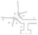
도 1은 본 발명에 따른 가슴 마사지용 유축기의 핵심 구성을 도시한 단면도이다.1 is a cross-sectional view showing the core configuration of the breast massage breast pump according to the present invention.
도 1을 참조하면, 본 발명에 따른 가슴마사지용 유축기는 공기압을 제공하는 본체(1)에 연결되어 있는 공기 유통관(11)이 실드(10)의 통공(14)으로 연결이 되고, 공기 유통관(11)의 일 측 하부로는 모유 배출관(12)이 형성되어 이에 우유병(13)이 결합될 수 있으며, 실드(10)는 공지의 실드와 마찬가지로 깔때기 형상을 가지되, 산모의 가슴(B)이 밀착하였을 경우 유륜(N)이 위치하는 내측 부위에 마사지 패드(20)를 구비하고 있다.Referring to Figure 1, the breast massage breast pump according to the present invention is connected to the air flow pipe (11) connected to the
또한, 마사지 패드(20)의 외측 방향으로는 실드(10) 벽체를 관통한 실드관(30)이 연결되어 있고, 이러한 실드관(30)은 본체(1)의 공기압 제공 모듈(40)과 연결이 되어 있다.In addition, a
본 발명에 따른 마사지 패드(20)는 실드(10) 내벽에 부착되어 신축성 및 탄성력이 강한 재질로 이루어진 박막의 플레이트 형상을 가진 것으로, 고무 재질 내지 얇은 두께의 실리콘 재질로 이루어질 수가 있으며 실드관(30)에서 유입되는 흡 입 내지 배출에 따른 공기압에 의하여 팽창 및 수축이 가능한 구조로 이루어져 있다.The
이러한 마사지 패드(20)는 유륜(N) 주변에 1쌍으로 구비되어 양 방향에서 유륜(N)을 자극할 수 있으나, 마사지 패드(20)의 개수는 2개 이상의 개수로 구비되는 것도 가능하며 결국 본 발명에 따른 마사지 패드(20)는 특정 개수에 국한되는 것은 아니다.The
더불어, 유아가 유륜(N)을 물기 위해 입 모양을 둥글게 할 경우 입술에 물결 형상의 라인이 형성되는 것에 착안하여 마사지 패드(20)의 실드(10) 내측 방향 면에는 외측으로 돌출된 복수 개의 돌기(21)가 형성되어 있다.In addition, when the infant rounds the shape of the mouth to bite the areolas N, a plurality of protrusions protruding outward on the inner surface of the
이러한 마사지 패드(20)의 작용을 기본적으로 설명하면, 실드관(30)을 통해 공기가 유입되는 배출 압력이 가해질 경우에는 마사지 패드(20)가 실드(20) 내측 방향으로 부풀어 올라 주변에 위치한 유륜(N)을 자극할 수 있고, 실드관(30)에서 공기가 방출되어 흡입 압력이 작용할 때에는 마사지 패드(20)는 실드(10) 외측으로 향하여 다시금 원 상태를 유지하는 작용을 가진다.Basically explaining the operation of the
실드관(30)으로 유입되는 공기압은 본체(1)에 형성된 공기압 제공 모듈(40)에 의하여 제공이 되며, 이는 도 5를 참조하며 후술하기로 한다.Air pressure flowing into the
도 2는 본 발명에 따른 실드(10)의 통공(14) 주변에 추가적으로 형성된 유륜 수용부(15)를 도시한 단면도이다.2 is a cross-sectional view showing the
도 2를 보아 알 수 있듯이, 실드(10)의 통공(14) 주변에는 산모의 유륜(N)이 수용될 수 있는 역할을 제공하는 유륜 수용부(15)가 형성되어 있는 것을 알 수 있다.As can be seen from Figure 2, it can be seen that around the through
이렇게 유륜 수용부(15)가 형성되어 있는 실드(10)에서는 상기 마사지 패드(20)는 이 유륜 수용부(15) 부위에 형성되어 있게 된다.In the
이러한 유륜 수용부(15)는 산모의 유륜(N) 형상 및 체적에 상응하거나 약간 더 큰 구조로 이루어져 있으며, 이를 통해 실드(10)가 산모의 가슴(B)에 부착되었을 때 유륜(N)과 실드(10) 내벽 사이에 이격 거리가 발생하여 마사지 패드(20)가 유륜(N)에 원활하게 접촉되지 않은 문제점을 해소할 수 있다.The
도 3은 본 발명에 따른 실드 구조의 공기압 작용을 설명하기 위한 본체(1) 구성에 대한 블록도이다.3 is a block diagram of the structure of the
먼저, 본 발명에 따른 실드 구조를 이루기 위한 본체(1)는 공지의 모터 구동부를 구비한 펌프와 별개, 또는 펌프를 개량한 기능을 가지는 공기압 제공 모듈(40)을 구비하고 있다.First, the
구체적으로, 본 발명에 따른 공기압 제공 모듈(40)은 기존 실드(10)의 통공(14)으로 흡입 및 배출 압력을 작용하여 강제로 산모의 유륜(N)에서 모유를 추출하는 메인 압력 제공부(41)를 포함하거나 별도 구비하고, 이외에 유륜 압력 제공부(42) 및 가슴 압력 제공부(43)를 구비하고 있다. 이러한 압력 제공부(41,42,43)는 기본적으로 모터의 구동에 의하여 공기압을 발생하는 것으로서 모터는 하나 이상으로 이루어져 각각의 모터마다 각각의 압력 제공부(41,42,43)를 담당하는 것이 가능하다.Specifically, the air
유륜 압력 제공부(42)는 유륜(N) 주변에 형성되어 있는 마사지 패드(20)에 공기압을 작용하는 기능을 제공하는 것이고, 가슴 압력 제공부(43)는 도 5 이하를 참조하여 후술하겠지만 유륜(N) 이외의 기타 가슴(B) 부위에 공기압을 제공하는 역할을 수행한다.The ring
이러한 각각의 압력 제공부(41,42,43)는 각 모터에 의하여 독립적으로 구동되는 것도 가능하나, 바람직하게는 메인 압력 제공부(41)와 유륜 압력 제공부(42)는 제어부(44)에 의하여 상호 압력 제어가 가능한 방식으로 이루어져 있다.Each of the
본 발명에 따른 제어부(44)는 메인 압력 제공부(41)가 흡입 압력을 가질 때, 유륜 압력 제공부(42)에는 배출 압력을 가지도록 압력을 조절하는 기능을 수행하며, 이는 도 4를 통해 구체적으로 설명이 되어 질 것이다.The
또한 본 발명에 따른 공기압 제공 모듈(40)은 압력 조절부(45)를 구비하여 실드(10)에 작용하는 각 압력 제공부(41,42,43)의 압력의 세기를 산모의 선택에 의하여 조절하는 것이 가능하며, 이러한 조절은 조절 스위치(46)의 조작에 의하여 달성이 된다.In addition, the air
도 4는 본 발명에 따른 유축기 실드 구조에 산모의 가슴이 착용된 상태에서 압력 방향을 도시한 단면도이다.Figure 4 is a cross-sectional view showing the pressure direction in the breast of the mother is worn on the breast pump shield structure according to the present invention.
메인 압력 제공부(41)는 공기의 흡입과 배출을 반복하되 흡입 시에 모유가 유륜(N)으로부터 빨려 나가는데, 만일 모유가 제대로 추출이 되지 않을 경우 공지 의 유축기에서는 압력 세기만 강화하여 유륜(N)에 상당한 통증을 유발하는 문제점이 있음을 본 발명자는 인식하여, 본 발명에 따른 제어부(44)에서 메인 압력 제공부(41)에 적은 압력을 제공하면서도 산모의 통증을 완화함과 동시에 착유의 극대화를 이루는 방식으로 메인/유륜 압력 조절부(41,42)의 압력을 상호 제어하도록 한다.The main
구체적으로, 메인 압력 제공부(41)에서 a1 방향으로 흡입 압력(모유를 추출하는 압력)이 작용할 경우에는, 유륜 압력 제공부(42)에서는 b1 방향으로 배출 압력이 작용하여 마사지 패드(20)를 실드(20) 내측 방향으로 팽창시켜 유륜(N)과의 접촉을 최대화한다.Specifically, when the suction pressure (pressure for extracting breast milk) acts in the a1 direction in the main
즉, 모유가 추출되는 순간에 마사지 패드(20)가 유륜(N)을 자극하도록 함으로 메인 압력 조절부(41)의 적은 압력에 의해서도 모유가 원활하게 추출되도록 하였다.That is, the
반대로, 메인 압력 제공부(41)에서 a2 방향으로 배출 압력이 작용할 경우, 유륜 압력 제공부(42)에서는 b2 방향으로 흡입 압력을 제공하여 마사지 패드(20)가 유륜(N)에서 이격될 수 있도록 한다.On the contrary, when the discharge pressure acts in the a2 direction in the main
이와 같이, 본 발명에 따른 실드 구조는 유륜(N)이 마사지 패드(20)에 의하여 마사지가 됨과 동시에 제어부(44)의 압력 제어 방식에 의하여 보다 적은 압력으로 착유의 극대화를 이룰 수 있으므로 산모가 느끼는 통증이 현저히 완화될 수 있는 특성을 제공한다.As described above, the shield structure according to the present invention can maximize the milking at a lower pressure by the pressure control method of the
도 5는 본 발명에 따른 변형된 실드 구조를 도시한 분해 사시도이다.5 is an exploded perspective view showing a modified shield structure according to the present invention.
마사지 패드(20)는 실드(10)의 유륜(N) 접촉 부위뿐 아니라, 기타 가슴(B) 부위에 접촉되는 실드(10) 내측 면에 형성하여 가슴(B)의 마사지를 이룰 수 있는 기능을 동시에 제공할 수 있으며, 이 때 마사지 패드(20)에 상응하는 개수의 실드관(30)을 형성하여 이를 도 5에서 언급한 가슴 압력 제공부(43)에 연결하여 배출 및 흡입 압력을 제공하는 것이 가능하다.
더 나아가, 유륜(N)에 집중적인 압력을 제공하여 유륜(N) 부위에만 간편하게 실드(10)를 착용하는 것이 가능하도록 본 발명에 따른 실드(10)는 2개로 분리가 가능하다.Furthermore, the
도 5를 참조하면, 본 발명에 따른 실드(10)는 유륜(N) 부위를 수용하는 유륜 실드(10a)와 유륜(N) 이외의 가슴(B) 부위를 수용하는 가슴 실드(10b)로 이루어져 있으며 양 실드(10a,10b)는 서로 탈부착 가능하게 이루어져 있다.Referring to FIG. 5, the
즉, 유륜 및 가슴 실드(10a,10b)의 양 단에는 나사산이 형성되어 나사산 결합이 가능한 방식으로 이루어지는 것이 가능하며, 아니면 도 5(a)에 도시된 바와 같이 요철부(61,62)를 각 실드 양단에 각각 대응 형성하여 종 방향으로 작용하는 외력에 의하여 결합 및 해제가 가능한 방식으로 이루어질 수 있다.That is, both ends of the areola and the chest shields 10a and 10b may be formed in a manner in which threads are formed so that the threads can be coupled, or as shown in FIG. Correspondingly formed at both ends of the shield can be made in a manner that can be coupled and released by an external force acting in the longitudinal direction.
더불어, 유륜 및 가슴 실드(10a,10b)의 각 마사지 패드(20)에 연결되어 있는 실드관(30)이 외부로 노출이 되어 있을 경우에는 서로 엉키거나 보관하기 불편한 사용 상 번거로움이 따를 수 있는 우려가 있기 때문에, 본 발명에 따른 실드(10)의 벽체를 약간 두껍게 구성하고 이 내부에 실드관(30)이 지나갈 수 있는 관로를 형성 하는 것이 가능하다.In addition, when the
이렇게 실드(10) 벽체 사이로 실드관(30)이 형성되어 있는 것은 도 1,2의 단일 실드 구조에서도 물론 가능하며, 이렇게 실드(10) 벽체 내로 실드관(30)이 지나갈 경우에는 본체(1)와의 연결을 위한 공기 유통관(11) 및 주변 부위를 보다 두껍게 형성하여 실드관(30)이 공기 유통관(11)과 일체적으로 형성되는 구조를 가지는 것이 전체적으로 심플한 구조를 제공할 수 있다는 점에서 보다 바람직하다.The
도 5(a)와 같이 유륜 실드(10a)와 가슴 실드(10b)가 결합할 때에는 도 5(b)와 같이 유륜 실드(10a) 및 가슴 실드(10b)의 결합 일 측에 형성되어 있는 실드관 체결부(51,52)에 의하여 실드관(30)은 서로 연결이 가능하다. 물론, 각 실드(10a,10b)의 결합 방식은 상기 설명에 한정되는 것은 아니고 공지되어 있는 다양한 방식에 의하여 변경 설계가 가능하다.When the
실드관 체결부(51,52)에 대해 보다 구체적으로 설명하면, 유륜 실드(10a)의 단부에는 노즐과 같이 돌출 형식의 관로(51)를 형성하고 가슴 실드(10b)의 대향 단에는 상기 돌출 형식의 관로(51)가 결합될 수 있는 홈 형식의 관로(52)가 형성되어 본체(1)로부터 유륜 실드(10a)를 통해 연장이 된 실드관(20) 중 가슴 실드(10b)에 공기압을 전달하는 실드관(30)을 연결하는 것이 가능하다. 실드관 체결부(51,52)는 가슴 실드(10b)에 형성된 마사지 패드(20)로의 공기 공급을 위한 대략 5-10개의 실드관(30)을 1세트로 한다 가정하였을 때 양 측으로 2 세트로서 구비되어 하나의 실드관 체결부(51,52)에서 가슴 실드(10b)의 내벽을 따라 사방으로 실드관(30)이 분산될 때 서로 교차 등의 문제로 실드관(30) 설치에 애로 사항이 있는 문제점을 해 소할 수 있다.The shield
이렇게 가슴 실드(10b)의 실드(10) 벽체 내로 연결된 실드관(30)은 가슴 실드(10b)의 가슴 실드(10b) 전반에 대해 고른 분포를 가지도록 분산 배치되어 각기 연결된 마사지 패드(20)에 압력을 제공하여 가슴(B)의 여러 부위를 마사지할 수 있는 특성을 제공한다.Thus, the
도 6은 도 5에 따른 유축기의 분리 실드 구조에 산모 가슴(B)이 수용된 상태를 도시한 단면도이다.6 is a cross-sectional view illustrating a state where the mother breast B is accommodated in the separate shield structure of the breast pump according to FIG. 5.
도 6을 보아 알 수 있듯이, 본 발명에 따른 유축기의 실드에 의하면 유륜(N) 뿐 아니라 기타 가슴(B) 부위의 마시지 기능을 수행함으로써 유선에서의 모유 생성을 촉진함과 동시에 마치 신생아가 젖을 무는 과정과 유사하게 유륜(N)을 자극함으로 통증을 느끼지 않을 정도의 적은 압력으로도 착유의 극대화를 이루는 것이 가능하며, 특히 유륜(N)만의 집중적인 마사지 기능을 요망할 경우에는 가슴 실드(10b)를 유륜 실드(10a)에서 분리하여 유륜 실드(10a)만을 가슴(B)에 부착 사용할 수 있는 간편한 사용 방식과 편의성을 제공할 수 있다.As can be seen from Figure 6, according to the shield of the breast pump according to the present invention by performing the massage function of not only the raceway (N) but also the other breast (B) area to promote the production of breast milk in the mammary gland and at the same time as newborn newborn milking Similar to the process, it is possible to maximize milking with little pressure so as not to feel pain by stimulating the auricle (N), especially when a intensive massage function of the auricle (N) is desired. It can be separated from the ring shield (10a) can provide a simple use method and convenience that can be used to attach only the ring shield (10a) to the chest (B).
지금까지 설명한 바와 같이, 본 발명에 따른 가슴 마사지용 유축기의 구성 및 작용을 상기 설명 및 도면에 표현하였지만 이는 예를 들어 설명한 것에 불과하여 본 발명의 사상이 상기 설명 및 도면에 한정되지 않으며, 본 발명의 기술적 사상을 벗어나지 않는 범위 내에서 다양한 변화 및 변경이 가능함은 물론이다.As described so far, the configuration and operation of the breast massage breast pump according to the present invention have been expressed in the above description and the drawings, but this is merely described by way of example and the spirit of the present invention is not limited to the above description and the drawings. Of course, various changes and modifications are possible without departing from the technical spirit of the.
이상에서 설명한 바와 같이, 본 발명에 따른 가슴 마사지용 유축기에 따르면,As described above, according to the breast massage breast pump according to the present invention,
1) 유륜 부위에 신축이 가능한 마사지 패드를 직접적으로 접촉하도록 함으로서 마치 신생아가 입으로 젖을 빠는 것과 같은 효과를 창출할 수 있는 장점을 가지고,1) By directly contacting the stretchable massage pad to the areola area, it has the advantage that it can create an effect like sucking a newborn baby into the mouth,
2) 실드의 메인 압력이 팽창하고 흡입되는 과정에서 반대적인 압력을 마사지 패드에 제공함으로서 보다 적은 압력으로 착유의 극대화를 이룰 수 있을 뿐 아니라,2) Maximize milking with less pressure by providing the opposite pressure to the massage pad during the expansion and suction of the shield's main pressure,
3) 강제로 모유를 추출하는 과정에서 산모가 느끼는 통증을 최소화할 수 있으며,3) It is possible to minimize the pain felt by the mother in the process of forcibly extracting breast milk,
4) 실드를 이단으로 탈부착 가능하게 분리함으로 유륜 부위의 마사지를 집중함과 동시에 실드의 가슴 착용의 간편화를 도모할 수 있다는 효과를 가진다.4) By separating the shield detachably in two stages, it is possible to concentrate the massage of the areola and to simplify the wearing of the shield's chest.
Claims (7)
Translated fromKoreanPriority Applications (1)
| Application Number | Priority Date | Filing Date | Title |
|---|---|---|---|
| KR1020070002885AKR100826938B1 (en) | 2007-01-10 | 2007-01-10 | Breast Massager Breast Pump |
Applications Claiming Priority (1)
| Application Number | Priority Date | Filing Date | Title |
|---|---|---|---|
| KR1020070002885AKR100826938B1 (en) | 2007-01-10 | 2007-01-10 | Breast Massager Breast Pump |
Publications (1)
| Publication Number | Publication Date |
|---|---|
| KR100826938B1true KR100826938B1 (en) | 2008-05-02 |
Family
ID=39649503
Family Applications (1)
| Application Number | Title | Priority Date | Filing Date |
|---|---|---|---|
| KR1020070002885AExpired - Fee RelatedKR100826938B1 (en) | 2007-01-10 | 2007-01-10 | Breast Massager Breast Pump |
Country Status (1)
| Country | Link |
|---|---|
| KR (1) | KR100826938B1 (en) |
Cited By (1)
| Publication number | Priority date | Publication date | Assignee | Title |
|---|---|---|---|---|
| WO2012046963A3 (en)* | 2010-10-04 | 2012-06-07 | Lee Keou Won | Breast pump unit |
Citations (5)
| Publication number | Priority date | Publication date | Assignee | Title |
|---|---|---|---|---|
| KR970060728U (en)* | 1996-05-29 | 1997-12-10 | 유선목 | Breast milk |
| KR19990041775U (en)* | 1998-05-26 | 1999-12-27 | 위해성 | Soft pad for breast milking machine |
| US6383164B1 (en) | 2000-09-26 | 2002-05-07 | Gerber Products Company | Massaging breast pump and funnel therefor |
| US20040015127A1 (en)* | 2001-06-22 | 2004-01-22 | Silver Brian H. | Breastshield with multi-pressure and expansible chamber construction, related breastpump and method |
| KR20040071263A (en)* | 2001-12-27 | 2004-08-11 | 플레이텍스 프로덕츠, 인크. | Breast Cup |
- 2007
- 2007-01-10KRKR1020070002885Apatent/KR100826938B1/ennot_activeExpired - Fee Related
Patent Citations (5)
| Publication number | Priority date | Publication date | Assignee | Title |
|---|---|---|---|---|
| KR970060728U (en)* | 1996-05-29 | 1997-12-10 | 유선목 | Breast milk |
| KR19990041775U (en)* | 1998-05-26 | 1999-12-27 | 위해성 | Soft pad for breast milking machine |
| US6383164B1 (en) | 2000-09-26 | 2002-05-07 | Gerber Products Company | Massaging breast pump and funnel therefor |
| US20040015127A1 (en)* | 2001-06-22 | 2004-01-22 | Silver Brian H. | Breastshield with multi-pressure and expansible chamber construction, related breastpump and method |
| KR20040071263A (en)* | 2001-12-27 | 2004-08-11 | 플레이텍스 프로덕츠, 인크. | Breast Cup |
Cited By (1)
| Publication number | Priority date | Publication date | Assignee | Title |
|---|---|---|---|---|
| WO2012046963A3 (en)* | 2010-10-04 | 2012-06-07 | Lee Keou Won | Breast pump unit |
Similar Documents
| Publication | Publication Date | Title |
|---|---|---|
| US9248223B2 (en) | Insert for a breast pump | |
| US6273868B1 (en) | Breast pump | |
| JP4169271B2 (en) | Breast cup and breast cup manufacturing method | |
| JP5948406B2 (en) | Milking machine | |
| US4772262A (en) | Portable electric breast pump | |
| JP5722886B2 (en) | Milker insert | |
| KR20010072907A (en) | Breast pump insert | |
| JP2525832Y2 (en) | Breast pump flange | |
| BR112019026558A2 (en) | BREAST MILK PUMP UNIT FOR USE WITH A BREAST MILK PUMP SYSTEM FOR BREAST BREAST PUMPING AND PUMP SYSTEM FOR BREAST MILK | |
| JP2023099978A (en) | Milker | |
| JP7593957B2 (en) | Breast pump | |
| CA2240268A1 (en) | Breast pump assembly | |
| KR100826938B1 (en) | Breast Massager Breast Pump | |
| CN202036597U (en) | Breast suction cover and breast pump with same | |
| CN212854209U (en) | Breast pump with massage function | |
| US20210402204A1 (en) | Breast Care Device | |
| KR101653355B1 (en) | Multi breast forming device | |
| CN221845630U (en) | Breast pump with physiotherapy function | |
| CN214761643U (en) | Inflatable toe separator | |
| KR20250000638U (en) | Breast shield with bump | |
| KR200296856Y1 (en) | Manual pumping device of milking machine | |
| CN2315962Y (en) | Multifunction pocket lactigenous milk-pump | |
| CN110959929A (en) | Child whole massage clothes |
Legal Events
| Date | Code | Title | Description |
|---|---|---|---|
| A201 | Request for examination | ||
| PA0109 | Patent application | St.27 status event code:A-0-1-A10-A12-nap-PA0109 | |
| PA0201 | Request for examination | St.27 status event code:A-1-2-D10-D11-exm-PA0201 | |
| D13-X000 | Search requested | St.27 status event code:A-1-2-D10-D13-srh-X000 | |
| D14-X000 | Search report completed | St.27 status event code:A-1-2-D10-D14-srh-X000 | |
| E902 | Notification of reason for refusal | ||
| PE0902 | Notice of grounds for rejection | St.27 status event code:A-1-2-D10-D21-exm-PE0902 | |
| E13-X000 | Pre-grant limitation requested | St.27 status event code:A-2-3-E10-E13-lim-X000 | |
| P11-X000 | Amendment of application requested | St.27 status event code:A-2-2-P10-P11-nap-X000 | |
| P13-X000 | Application amended | St.27 status event code:A-2-2-P10-P13-nap-X000 | |
| T11-X000 | Administrative time limit extension requested | St.27 status event code:U-3-3-T10-T11-oth-X000 | |
| E701 | Decision to grant or registration of patent right | ||
| PE0701 | Decision of registration | St.27 status event code:A-1-2-D10-D22-exm-PE0701 | |
| GRNT | Written decision to grant | ||
| PR0701 | Registration of establishment | St.27 status event code:A-2-4-F10-F11-exm-PR0701 | |
| PR1002 | Payment of registration fee | St.27 status event code:A-2-2-U10-U11-oth-PR1002 Fee payment year number:1 | |
| PG1601 | Publication of registration | St.27 status event code:A-4-4-Q10-Q13-nap-PG1601 | |
| LAPS | Lapse due to unpaid annual fee | ||
| PC1903 | Unpaid annual fee | St.27 status event code:A-4-4-U10-U13-oth-PC1903 Not in force date:20110426 Payment event data comment text:Termination Category : DEFAULT_OF_REGISTRATION_FEE | |
| PC1903 | Unpaid annual fee | St.27 status event code:N-4-6-H10-H13-oth-PC1903 Ip right cessation event data comment text:Termination Category : DEFAULT_OF_REGISTRATION_FEE Not in force date:20110426 | |
| P22-X000 | Classification modified | St.27 status event code:A-4-4-P10-P22-nap-X000 | |
| R18-X000 | Changes to party contact information recorded | St.27 status event code:A-5-5-R10-R18-oth-X000 | |
| P22-X000 | Classification modified | St.27 status event code:A-4-4-P10-P22-nap-X000 |