KR100826467B1 - Test handler and switchgear for test handler - Google Patents
Test handler and switchgear for test handlerDownload PDFInfo
- Publication number
- KR100826467B1 KR100826467B1KR1020050124225AKR20050124225AKR100826467B1KR 100826467 B1KR100826467 B1KR 100826467B1KR 1020050124225 AKR1020050124225 AKR 1020050124225AKR 20050124225 AKR20050124225 AKR 20050124225AKR 100826467 B1KR100826467 B1KR 100826467B1
- Authority
- KR
- South Korea
- Prior art keywords
- opening
- inlet
- closing member
- test
- outlet
- Prior art date
- Legal status (The legal status is an assumption and is not a legal conclusion. Google has not performed a legal analysis and makes no representation as to the accuracy of the status listed.)
- Active
Links
- 238000012360testing methodMethods0.000titleclaimsabstractdescription116
- 230000000903blocking effectEffects0.000claimsabstractdescription14
- 230000004308accommodationEffects0.000claimsdescription21
- 238000002347injectionMethods0.000claimsdescription8
- 239000007924injectionSubstances0.000claimsdescription8
- 238000000034methodMethods0.000claimsdescription8
- 238000003825pressingMethods0.000claimsdescription8
- 238000005507sprayingMethods0.000claims1
- 230000004888barrier functionEffects0.000abstractdescription2
- 238000005516engineering processMethods0.000abstractdescription2
- 230000000694effectsEffects0.000description4
- 238000010586diagramMethods0.000description3
- 238000009413insulationMethods0.000description3
- 239000004065semiconductorSubstances0.000description2
- 239000004593EpoxySubstances0.000description1
- 206010034719Personality changeDiseases0.000description1
- 238000004891communicationMethods0.000description1
- 230000005684electric fieldEffects0.000description1
- 238000004519manufacturing processMethods0.000description1
- 239000000463materialSubstances0.000description1
- 238000011084recoveryMethods0.000description1
- 238000000926separation methodMethods0.000description1
Images


Classifications
- G—PHYSICS
- G01—MEASURING; TESTING
- G01R—MEASURING ELECTRIC VARIABLES; MEASURING MAGNETIC VARIABLES
- G01R31/00—Arrangements for testing electric properties; Arrangements for locating electric faults; Arrangements for electrical testing characterised by what is being tested not provided for elsewhere
- G01R31/28—Testing of electronic circuits, e.g. by signal tracer
- G01R31/2851—Testing of integrated circuits [IC]
- G01R31/2855—Environmental, reliability or burn-in testing
- G01R31/286—External aspects, e.g. related to chambers, contacting devices or handlers
- G01R31/2865—Holding devices, e.g. chucks; Handlers or transport devices
- G01R31/2867—Handlers or transport devices, e.g. loaders, carriers, trays
- G—PHYSICS
- G01—MEASURING; TESTING
- G01R—MEASURING ELECTRIC VARIABLES; MEASURING MAGNETIC VARIABLES
- G01R1/00—Details of instruments or arrangements of the types included in groups G01R5/00 - G01R13/00 and G01R31/00
- G01R1/02—General constructional details
- G01R1/04—Housings; Supporting members; Arrangements of terminals
- G01R1/0408—Test fixtures or contact fields; Connectors or connecting adaptors; Test clips; Test sockets
- G01R1/0433—Sockets for IC's or transistors
- G01R1/0441—Details
- G01R1/0466—Details concerning contact pieces or mechanical details, e.g. hinges or cams; Shielding
- G—PHYSICS
- G01—MEASURING; TESTING
- G01R—MEASURING ELECTRIC VARIABLES; MEASURING MAGNETIC VARIABLES
- G01R31/00—Arrangements for testing electric properties; Arrangements for locating electric faults; Arrangements for electrical testing characterised by what is being tested not provided for elsewhere
- G01R31/28—Testing of electronic circuits, e.g. by signal tracer
- G01R31/2851—Testing of integrated circuits [IC]
- G01R31/2893—Handling, conveying or loading, e.g. belts, boats, vacuum fingers
Landscapes
- Engineering & Computer Science (AREA)
- Computer Hardware Design (AREA)
- Microelectronics & Electronic Packaging (AREA)
- Physics & Mathematics (AREA)
- General Physics & Mathematics (AREA)
- General Engineering & Computer Science (AREA)
- Environmental & Geological Engineering (AREA)
- Testing Of Individual Semiconductor Devices (AREA)
Abstract
Translated fromKoreanDescription
Translated fromKorean도1은 종래의 테스트핸들러에 대한 개략도이다.1 is a schematic diagram of a conventional test handler.
도2 및 도3은 도1의 테스트핸들러의 배치구조에 대해 평면에서 바라본 개략적인 구조도이다.2 and 3 are schematic structural views in plan view of the arrangement of the test handler of FIG.
도4는 본 발명의 실시예에 따른 테스트핸들러에서 소크 챔버 및 테스트 챔버의 내부구조를 측면에서 본 개략도이다.Figure 4 is a schematic side view of the soak chamber and the internal structure of the test chamber in the test handler according to an embodiment of the present invention.
도5 및 도6은 도4의 테스트핸들러에 적용된 개폐장치에 대한 사시도이다.5 and 6 are perspective views of the opening and closing device applied to the test handler of FIG.
도7a 내지 도9c는 도5의 개폐장치의 작동상태를 도시한 측단면도이다.7A to 9C are side cross-sectional views showing an operating state of the switching device of FIG.
*도면의 주요부분에 대한 부호의 설명** Description of the symbols for the main parts of the drawings *
500 : 개폐장치 510 : 개폐부재500: switchgear 510: switchgear
520 : 공압실린더 531 : 회전바520: pneumatic cylinder 531: rotating bar
532 : 가압부재 533 : 동력원532: pressure member 533: power source
540 : 탄성지지장치 541 : 스프링540: elastic support device 541: spring
542 : 롤러542: Roller
본 발명은 생산된 반도체 디바이스를 검사하기 위한 테스트핸들러에 관한 것이다.The present invention relates to a test handler for inspecting a produced semiconductor device.
일반적으로 테스트핸들러는 소정의 제조공정을 거쳐 제조된 반도체 디바이스(이하 디바이스라 칭함)를 테스트하며, 테스트 결과에 따라 디바이스들을 등급별로 분류하여 유저트레이에 적재하는 기기로서 이미 다수의 공개문서들을 통해 공개되어 있다.In general, a test handler tests a semiconductor device (hereinafter referred to as a device) manufactured through a predetermined manufacturing process, and classifies devices according to test results and loads them into a user tray. It is.
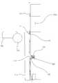
도1은 그러한 테스트핸들러에 대한 종래기술에 따른 개략도로서, 도1을 참조하여 종래의 테스트핸들러에 대하여 개략적으로 설명하면 다음과 같다.FIG. 1 is a schematic diagram according to the prior art for such a test handler, which will be described schematically with reference to FIG. 1.
도1에 도시된 바와 같이, 종래의 테스트핸들러는 로딩장치(120), 수직 자세변환장치(130), 소크 챔버(200), 테스트 챔버(100), 디소크 챔버(300), 수평 자세변환장치(230), 언로딩장치(260)을 갖추고 있다.As shown in FIG. 1, the conventional test handler includes a
상기 로딩장치(120)는, 부호 110의 유저트레이에 적재된 디바이스를 수평상태의 테스트트레이로 로딩(이송 및 적재)시킨다.The
상기 수직 자세변환장치(130)는, 소크 챔버(200)의 상방향에 위치하며, 소크 챔버(200)로 테스트트레이를 공급하기에 앞서 수평상태의 테스트트레이를 수직상태로 자세변환시킨다.The vertical
상기 소크 챔버(200)는, 상기 자세변환장치(130)에 의해 수직상태로 자세변환된 테스트트레이를 순차적으로 수용하며, 테스트트레이에 적재된 디바이스를 예열/예냉시키기 위한 온도적 환경이 조성되어 있다. 이러한 소크 챔버(200)에 진입된 테스트트레이는 수직상태를 유지한 채 테스트 챔버(100) 측에 가까운 방향으로 병진이동하면서 순차적으로 배열되는데, 이렇게 병진이동하는 시간동안, 테스트트레이에 담긴 디바이스가 충분히 예열/예냉된다.The
상기 테스트 챔버(100)는, 소크 챔버(200)로부터 공급되어 온 테스트트레이(180, 190)에 적재된 디바이스를 테스트하기 위해 마련된다. 이를 위해 테스트 챔버(100)는 디바이스를 테스트하기 위한 온도적 환경이 조성되어 있다.The
그리고 소크 챔버(200)와 테스트 챔버(100)는 서로 연통되어 있다.The
상기 디소크 챔버(300)(일명, 회복챔버라 함)는 고온 또는 냉각상태의 디바이스를 상온으로 환원시키기 위해 마련된다.The desock chamber 300 (also called a recovery chamber) is provided to reduce the device at a high temperature or a cooled state to room temperature.
상기 수평 자세변환장치(230)는, 디소크 챔버(300)의 상방향에 위치하며, 디소크 챔버(300)로부터 이송된 수직상태의 테스트트레이를 수평상태로 자세변환시킨다.The horizontal
상기 언로딩장치(260)는, 테스트가 완료된 디바이스를 등급별로 분류하여 다시 부호 310의 유저트레이로 언로딩(이송 및 적재)시킨다.The
즉, 테스트핸들러에서는 유저트레이에서 테스트트레이로 로딩하는 과정에서부터 테스트가 완료된 디바이스를 테스트트레이로부터 유저트레이로 언로딩하는 과정까지 디바이스를 적재한 테스트트레이의 이동이 순차적으로 이루어진다.That is, in the test handler, the test tray in which the device is loaded is sequentially moved from the process of loading from the user tray to the test tray to the process of unloading the device from the test tray into the user tray.
도2 및 도3은 도1의 테스트핸들러를 평면에서 바라본 개략도로서, 도2에는 테스트핸들러 내에서 이루어지는 테스트트레이의 이송방향(a)과 디바이스의 이송방 향(b)이 표현되어 있고, 도3에는 테스트 챔버(100) 내에서 테스트대기부(100a)에서 대기하고 있는 테스트트레이를 테스트부(100b)로 이송시키기 위한 트레이이송장치(140)가 개략적으로 도시되어 있다. 도3에서 참조되는 바와 같이 테스트 챔버(100)는 테스트대기부(100a), 테스트부(100b) 및 출력대기부(100c)로 구성되어 있다. 테스트대기부(100a)에서는 소크 챔버(200)로부터 이동되어 온 테스트트레이가 테스트부(100b)로 이송되기에 앞서 대기하고 있고, 테스트부(100b)에서는 테스트대기부(100a)로부터 온 테스트트레이에 적재된 디바이스가 테스트되며, 출력대기부(100c)에서는 테스트부(100b)에서 테스트가 완료된 테스트트레이가 디소크 챔버(300)로 출력되기에 앞서 대기하고 있게 된다. 이와 같은 테스트 챔버(100)에서 테스트트레이는 첫째, 테스트대기부(100a)에서 테스트부(100b)로 이송되게 되며, 둘째, 테스트부(100b)에서 출력대기부(100c)로 이송되게 된다.2 and 3 are schematic views of the test handler of FIG. 1 in plan view, and FIG. 2 shows a conveying direction a of a test tray and a conveying direction b of a device in FIG. In the
그런데 상술한 소크 챔버(200) 및 테스트 챔버(100)는 외기와 열적으로 차단되어야할 필요성이 있으며, 이러한 열적인 차단은 소크 챔버(200)의 벽면과 테스트부(100b)와 출력대기부(100c) 사이의 차단벽(11)에 의해 차단된다. 물론, 부호 11의 차단벽(11)은 디소크 챔버(300)와 출력대기부(100c) 사이에 위치될 수도 있지만, 테스트공정의 효율성 및 에너지의 절감 차원에서 도2 및 도3에서와 같이 테스트부(100b)와 출력대기부(100c) 사이에 위치되는 것이 바람직하다.However, the
한편, 도2의 a루프에서 알 수 있는 바와 같이 테스트트레이는 그러한 소크 챔버의 벽이나 차단벽(11)들을 통과하여야 하므로, 소크 챔버(200)의 벽이나 차단벽(11)에는 테스트트레이를 수용하기 위한 입구나 또는 출구가 형성되어 있기 때문 에, 이러한 입구나 출구를 걔폐하기 위한 개폐장치가 별도로 구성되어야 한다. 그리고 입구나 출구 주위에는 열차단율을 높이기 위한 단열부재가 마련되어 있다.On the other hand, as can be seen in the loop a of FIG. 2, the test tray must pass through the walls or blocking
그런데, 단열부재는 입구나 출구의 열차단율을 우수하게 유지하도록 하지만, 개폐부재가 입구나 출구가 형성되어 있는 면에 평행하게 열리고 닫히게 하는 것, 즉, 미닫이식의 개폐를 곤란하게 한다. 왜냐하면, 개폐부재가 미닫이식으로 열리고 닫히게 구성되면, 개폐부재와 단열부재 간에 마찰이 발생하여 단열부재가 손상되어서 그 기능을 상실하게 되기 때문이다. 이러한 이유 때문에 개폐부재는 여닫이식으로 개폐하도록 구성되는데 이러한 경우에는 여닫이에 필요한 공간이 확보되어야 하기 때문에 장치의 사이즈가 확대되는 결과를 초래하는 문제점이 발생한다. 즉, 입구나 출구가 상방향에 형성되어 있는 경우에는 높이가 커지게 되고, 입구나 출구가 측면에 형성되는 경우에는 장치의 전장이나 폭이 확대되는 문제점이 있는 것이다.By the way, although the heat insulation member keeps the thermal cut-off rate of an inlet or an exit excellent, it makes it difficult to open and close parallel with the surface in which an inlet or an exit is formed, ie, a sliding type opening and closing. This is because, when the opening and closing member is configured to open and close in a sliding manner, friction occurs between the opening and closing member and the heat insulating member, and the heat insulating member is damaged to lose its function. For this reason, the opening and closing member is configured to open and close in a case that in this case there is a problem that results in the size of the device is enlarged because the space required for opening and closing. That is, when the inlet or the outlet is formed in the upper direction, the height is increased, and when the inlet or the outlet is formed on the side, there is a problem that the overall length or width of the device is expanded.
또한, 종래에는 개폐부재에 의해 입구나 출구가 폐쇄되었을 경우 개폐부재와 단열부재간의 긴밀한 접촉이 이루어지지 않는 점을 통해 입구나 출구의 폐쇄효과가 저감될 수 있었으나, 그러한 사항을 고려한 어떠한 장치적 구성도 고려되지 않고 있는 실정이다.In addition, in the related art, when the inlet or the outlet is closed by the opening / closing member, the closing effect of the inlet or the outlet may be reduced by not making intimate contact between the opening / closing member and the thermal insulation member. Neither is it considered.
본 발명은 상기한 문제점을 해결하기 위한 것으로, 개폐부재가 입구나 출구가 형성된 면에 평행한 방향으로 이동하면서 입구나 출구를 개폐시킬 수 있도록 하고, 더 나아가 개폐부재가 입구나 출구가 형성된 면에 평행한 방향으로 이동하면서도 타 요소와의 간섭 없이 이동할 수 있어서 장치의 열차단율을 유지시킬 수 있는 기술을 제공하는 것을 목적으로 한다.The present invention is to solve the above problems, the opening and closing member to move in the direction parallel to the surface on which the inlet or outlet is formed to open and close the inlet or outlet, and furthermore, the opening and closing member on the surface on which the inlet or outlet is formed It is an object of the present invention to provide a technology capable of moving in parallel directions without interference with other elements to maintain the thermal barrier ratio of the device.
또한, 본 발명은 열적인 차단이 필요한 양 공간의 입구나 출구를 개폐부재가 폐쇄하고 있지만 폐쇄의 긴밀성이 떨어지는 경우에도 폐쇄효과를 그대로 유지할 수 있는 기술을 제공하는 것을 또 다른 목적으로 한다.Further, another object of the present invention is to provide a technique capable of maintaining the closing effect even when the closing member closes the inlet or the outlet of both spaces requiring thermal shutoff, but the closeness of the closing is inferior.
상기한 목적을 달성하기 위한 본 발명에 따른 테스트핸들러는, 유저트레이에 적재된 디바이스를 테스트트레이로 로딩시키는 로딩장치; 로딩이 완료된 테스트트레이에 적재된 디바이스를 예열/예냉시키기 위해 마련되며, 전면에 테스트트레이를 수용하기 위한 수용입구가 형성된 소크 챔버; 상기 소크 챔버의 상기 수용입구를 개폐하는 개폐장치; 상기 로딩장치에 의해 로딩이 완료된 테스트트레이를 상기 수용입구를 통해 상기 소크 챔버의 내부로 입력시키는 입력장치; 상기 소크 챔버의 내부에서 상기 수용입구를 통해 수용되는 테스트트레이를 파지한 후 자세변환시키는 자세변환장치; 상기 소크 챔버로부터 공급되는 테스트트레이에 적재된 디바이스를 테스트하기 위해 마련되는 테스트챔버; 및 상기 테스트챔버에서 테스트가 완료된 디바이스를 유저트레이로 언로딩시키는 언로딩장치; 를 포함하는 것을 특징으로 한다.Test handler according to the present invention for achieving the above object, the loading device for loading the device loaded in the user tray into the test tray; A soak chamber provided for preheating / precooling the device loaded in the loaded test tray and having an accommodation inlet for accommodating the test tray in a front surface thereof; An opening and closing device for opening and closing the receiving opening of the soak chamber; An input device for inputting a test tray loaded by the loading device into the soak chamber through the accommodation inlet; A posture converting apparatus configured to grasp a test tray accommodated through the accommodation opening in the soak chamber and then change a posture; A test chamber provided for testing a device loaded in a test tray supplied from the soak chamber; And an unloading device for unloading the device, which has been tested in the test chamber, to a user tray. Characterized in that it comprises a.
상기 개폐장치는, 상기 수용입구를 개폐하기 위해 마련되는 개폐부재; 및 상기 개폐부재를 상기 수용입구가 형성된 벽면과 평행한 방향으로 이동시키는 이동장치; 를 포함하는 것을 특징으로 한다.The opening and closing device, the opening and closing member provided to open and close the receiving opening; And a moving device to move the opening and closing member in a direction parallel to the wall surface on which the accommodation opening is formed. Characterized in that it comprises a.
또한 상기한 목적을 달성하기 위한 본 발명에 따른 테스트핸들러용 개폐장치는, 차단벽에 의해 차단된 양 공간의 입구 또는 출구를 개폐하기 위해 마련되는 개폐부재; 및 상기 개폐부재를 상기 입구 또는 출구가 형성된 면과 평행한 방향으로 이동시키는 이동장치; 를 포함하는 것을 특징으로 한다.In addition, the test handler opening and closing device according to the present invention for achieving the above object, the opening and closing member provided to open and close the inlet or outlet of both spaces blocked by the blocking wall; And a moving device to move the opening and closing member in a direction parallel to a surface on which the inlet or the outlet is formed. Characterized in that it comprises a.
상기 개폐부재가 상기 입구 또는 출구 측으로 밀착되도록 가압하는 가압장치; 를 더 포함하는 것을 또 하나의 특징으로 한다.A pressurizing device for pressurizing the opening / closing member to be in close contact with the inlet or the outlet; It is characterized by another comprising a further.
상기 개폐부재가 상기 입구 또는 출구가 형성된 면과 유격을 가진 상태에서 평행이동할 수 있도록 상기 개폐부재를 상기 입구 또는 출구가 형성된 면으로부터 탄성지지하는 탄성지지장치; 를 더 포함하는 것을 또 하나의 특징으로 한다.An elastic support device for elastically supporting the opening / closing member from a surface on which the inlet or the outlet is formed so that the opening / closing member can move in parallel with the clearance between the surface on which the inlet or the outlet is formed; It is characterized by another comprising a further.
상기 입구 또는 출구가 형성된 면과 상기 개폐부재 사이의 유격공간으로 공기를 분사시키기 위한 공기분사장치; 를 더 포함하는 것을 또 하나의 특징으로 한다.An air injection device for injecting air into the clearance space between the inlet or outlet surface and the opening / closing member; It is characterized by another comprising a further.
상기 공기분사장치는, 상기 개폐부재를 향해 개방되도록 상기 입구 또는 출구가 형성된 면 쪽에 형성된 안착공간에 안착되어 상기 유격공간으로 공기를 분사시키는 노즐부재; 및 상기 노즐부재로 공기를 공급하는 공기공급장치; 를 포함하는 것을 또 하나의 특징으로 한다.The air injection unit, the nozzle member which is seated in the seating space formed on the surface side formed with the inlet or outlet so as to open toward the opening and closing member to inject air into the play space; And an air supply device supplying air to the nozzle member. It is another feature to include a.
또한, 상기한 목적을 달성하기 위한 본 발명에 따른 테스트핸들러용 개폐장치는, 차단벽에 의해 차단된 양 공간의 입구 또는 출구를 개폐하기 위해 마련되는 개폐부재; 상기 개폐부재를 개폐이동시키는 이동장치; 상기 개폐부재가 상기 입구 또는 출구가 형성된 면에 밀착되도록 가압하는 가압장치; 를 포함하는 것을 특징으로 한다.In addition, the opening and closing device for a test handler according to the present invention for achieving the above object, the opening and closing member provided to open and close the inlet or outlet of both spaces blocked by the blocking wall; A moving device for opening and closing the opening and closing member; A pressurizing device for pressing the opening / closing member to be in close contact with a surface on which the inlet or the outlet is formed; Characterized in that it comprises a.
상기 가압장치는, 회전가능하게 설치되는 회전바; 상기 회전바에 결합 또는 형성되어 있어서 상기 회전바의 회전에 의해 상기 개폐부재를 가압하거나 가압 해제하는 적어도 하나 이상의 가압부재; 및 상기 회전바를 회전시키기 위한 동력원; 을 포함하는 것을 특징으로 한다.The pressurizing device includes a rotating bar rotatably installed; At least one pressing member coupled to or formed on the rotating bar to press or release the opening / closing member by the rotation of the rotating bar; And a power source for rotating the rotating bar. Characterized in that it comprises a.
또한, 상기한 목적을 달성하기 위한 본 발명에 따른 테스트핸들러용 개폐장치는, 차단벽에 의해 차단된 양 공간의 입구 또는 출구를 개폐하기 위해 마련되며, 상기 입구 또는 출구와 대응되는 면에 상기 입구 또는 출구의 주변과 대응되도록 형성된 공기홈과 상기 공기홈과 연통되도록 형성된 공기입력유로를 포함하는 분사유로를 가지는 개폐부재; 및 상기 개폐부재의 공기입력유로로 공기를 공급하는 공기공급장치; 를 포함하는 것을 특징으로 한다.In addition, the test handler opening and closing device according to the present invention for achieving the above object is provided to open and close the inlet or outlet of both spaces blocked by the blocking wall, the inlet on the surface corresponding to the inlet or outlet Or an opening / closing member having an air flow path formed to correspond to the periphery of the outlet and an air input flow path formed to communicate with the air groove; And an air supply device supplying air to the air input flow path of the opening and closing member. Characterized in that it comprises a.
이하, 본 발명에 따른 하나의 바람직한 실시 예를 첨부도면을 참조하여 상세히 설명한다.Hereinafter, one preferred embodiment according to the present invention will be described in detail with reference to the accompanying drawings.
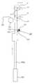
도4는 본 발명의 실시예에 따른 테스트핸들러(40)의 소크 챔버(400A) 및 테스트 챔버(400B)의 내부구조를 측면에서 본 개략도이다.4 is a schematic side view illustrating the internal structure of the soak
도4를 참조하면, 본 실시예에 따른 테스트핸들러(40)는, 소크 챔버(400A), 테스트 챔버(400B), 개폐장치(500), 자세변환장치(700) 및 입력장치(600) 등을 포 함하고 있다.Referring to FIG. 4, the
상기 소크 챔버(400A)는 상기 입력장치(600)에 의해 로딩부에서 로딩이 완료된 테스트트레이(20)를 수용한 후, 하방에 적재된 테스트트레이(20)를 순차적으로 이동시키면서 후방에 배치된 테스트 챔버(400B)로 공급하며, 이러한 과정 중에 테스트트레이(20)에 적재된 디바이스를 예열 또는 예냉시킨다. 또한, 소크 챔버(400A)의 전면에는 상기 입력장치(600)에 의해 입력되는 테스트트레이(20)를 수용하기 위한 수용입구(400a)가 형성되어 있다.The soak
상기 테스트 챔버(400B)는 상기 소크 챔버(400A)의 후방에 마련되며, 소크 챔버(400A)로부터 공급된 테스트트레이(20)에 적재된 디바이스를 테스트한 후 디소크 챔버(미도시)로 출력시킨다.The
상기 개폐장치(500)는 상기 소크 챔버(400A)의 수용입구(400a)를 개폐한다. 이러한 개폐장치(500)에 대하여 도5 및 도6과, 도7a 내지 도7c를 참조하여 더 상세히 설명하면 다음과 같다. 도5는 소크 챔버(400A)에 결합 설치되며 수용입구(400a)가 형성된 입구프레임(410)과 본 발명에 따른 개폐장치(500)가 결합된 결합사시도, 도6은 도5의 주요부위에 대한 분해사시도, 도7a는 도5의 A선을 자른 측단면도, 도7b 및 도7c는 도7a의 A 및 B 부분을 각각 확대한 확대도이다. 참고로, 본 실시예에서는 소크 챔버(400A)의 수용입구(400a)가 전면에 형성되어 있고, 또한, 별도로 구비된 단열을 위한 에폭시 재질의 입구프레임(410)이 형성되어 있으며, 개폐장치(500)가 입구프레임(410)에 결합되어 있는 예를 들고 있지만 실시하기에 따라서는 수용입구가 소크 챔버의 상방에 형성될 수도 있으며, 소크 챔버(400A)의 벽면에 수용입구가 직접 형성될 수도 있을 것이다.The opening and
상기 개폐장치(500)는 개폐부재(510), 이동장치, 가압장치, 탄성지지장치(540), 안내장치, 공기공급장치 및 에어분사장치 등을 포함하여 구성된다.The opening and
상기 개폐부재(510)는 수용입구(400a)를 개폐시키기 위하여 마련되며, 이러한 본 발명에 따른 개폐부재(510)는 상하방향으로 슬라이딩되면서 수용입구(400a)를 개폐시킨다. 그리고 개폐부재(510)의 하단은 후술할 공압실린더의 피스톤로드에 링크 결합되어 있으며, 개폐부재(510)에는 수용입구(400a) 방향으로 수용입구(400a) 주변에 대략적으로 사각형상으로 마련되는 단열부재(411)와 대응되는 면에 대략적으로 사각형상의 공기홈(511)이 형성되어 있다. 그리고 개폐부재(510)의 내부에는 공기홈(511)과 연통되어서 개폐부재(510)의 하단으로 개방된 공기입력유로(512)가 형성되어 있다.The opening and closing
상기 이동장치는, 공압실린더(520)를 포함하여 구성된다. 이러한 공압실린더(520)는 개폐부재(510)의 하방에 위치하며, 공압실린더(520)의 피스톤로드(520a)는 상술한 바와 같이 개폐부재(510)의 하단과 링크결합되어 있다.The moving device includes a
상기 가압장치는, 회전바(531), 가압부재(532) 및 동력원을 포함하여 구성된다.The pressurizing device includes a
상기 회전바(531)는, 상기 개폐부재(510)를 수평방향으로 가로질러 회전가능하도록 입구프레임(410)의 좌우 양단의 브래킷부(410a, 410b)에 결합되어 있다. 그리고 일측은 후술할 공압실린더(533, 이하 상기한 부호 520의 공압실린더와 구별하기 위해 '동력원'이라 함)의 피스톤로드(533a)와 링크(531a)에 의해 결합되어 있 다.The
상기 가압부재(532)는, 회전바(531)에 일정 간격으로 세 개가 결합되어 있다. 물론, 실시하기에 따라서는 적어도 하나 이상만 구비되면 바람직하게 적용될 수 있을 것이다.The pressing
상기 동력원(533)은 공압실린더로서 구비되며, 피스톤로드(533a)가 상술한 바와 같이 링크(531a)에 의해 회전바(531)에 연결되어 있다.The
따라서 동력원(533)이 작동하여 피스톤로드(533a)가 진퇴하면 회전바(531)가 회전함으로써 가압부재(532)가 회전바(531)의 회전방향으로 회전하면서 개폐부재(510)을 가압시키거나 가압해제시키게 된다.Therefore, when the
설명된 가압장치는 개폐부재가 입구나 출구를 긴밀하게 폐쇄시키도록 하기 위하여 마련된 것이며, 본 실시예에서처럼 미닫이 방식에서 바람직하게 적용될 수 있지만, 여닫이 방식에서 입구나 출구의 긴밀한 폐쇄를 요하는 경우에도 충분히 고려될 수 있는 요소이다.The pressurization device described is provided for the closing member to close the inlet or the outlet tightly, and may be preferably applied in the sliding type as in the present embodiment, but it is sufficiently considered even in the case of the closing type requiring the close closing of the inlet or the outlet. It can be a factor.
탄성지지장치(540)는 입구프레임(410)에 개폐부재(510)를 향하여 개방되도록 형성된 수용홈(510a)에 수용되는 스프링(541)과 이 스프링(541)에 의해 탄성지지되며 일측이 수용홈(510a)에 회전가능하도록 고정되고 타측은 스프링(541)의 탄성운동에 의해 전후진될 수 있도록 마련되는 레버(543) 및 레버(543)의 타측에 회전가능하게 결합되는 롤러(542)를 포함하여 구성된다.The
상기 안내장치는 상기 입구프레임(410)의 좌우 양단에 돌출된 돌출부(410R, 410L)에 결합된 판넬(560a, 560b)로 구성된다. 이러한 판넬(560a, 560b)은 개폐부 재(510)의 상하 이동을 안내하면서도 이탈을 방지하는 역할을 한다.The guide device includes
상기 공기공급장치는, 상기 개폐부재(510)의 공기입력유로(512)로 공기를 공급하여 궁극적으로 개폐부재(510)의 공기홈(511)에 공기를 공급하기 위한 장치로서, 개폐부재(510)의 하단에서 공기입력유로(512)에 결합되는 노즐(571)과, 공기를 공급하는 공압펌프(572)와, 노즐과 공압펌프를 연결하는 연결관(573) 등을 포함하여 구성된다. 여기서 공기공급장치에 의해 공급되는 공기는 소크 챔버(400A)에서 디바이스가 가열되느냐 냉각되느냐에 따라서 고온상태 또는 저온상태의 공기일 수 있다.The air supply device is a device for supplying air to the
상기 에어분사장치는, 상기 수용입구(400a)가 개방되었을 때, 수용입구(400a)에 고온 또는 저온 상태의 공기벽을 형성하여 소크 챔버(400A)의 내부를 외기로부터 보호하기 위한 것으로 노즐부재(581)와 에어공급장치를 포함하여 구성된다. 상기 노즐부재(581)는 상기 개폐부재(510)를 향해 개방되도록 상기 입구프레임(410)에 형성된 안착공간(412)에 안착되며, 상면은 대략 개폐부재(510)를 향하도록 테이퍼면으로 되어 있고, 내부에는 상면으로는 다수의 분사구(581a-1)를 가지며 하면으로는 두 개의 입력구(581a-2)를 가지는 분사유로(581a)가 형성되어 있다. 그리고 상기 에어공급장치는 상기 두 개의 입력구(581a-2)와 각각 결합되는 두개의 노즐(582)과 에어를 공급하는 에어펌프(583) 및 에어펌프(583)에서 공급되는 에어를 상기 두개의 노즐(582) 측으로 안내하는 안내관(584) 등을 포함하여 구성된다. 물론, 이러한 에어분사장치에서 공급되는 에어도 상기 공기공급장치에서 공급되는 공기와 동일하나 구성의 혼돈을 피하여 설명을 명확히 하기 위해 편의상 '공기' 및 '에어'로 정의하였을 뿐이다. 또, 상기한 공압펌프(572)와 에어펌프(583)는 하나의 구성으로 마련되고, 이러한 경우 제어에 의해 선택적으로 유로를 전환시키는 밸브를 구비시키도록 구현될 수도 있을 것이다.When the
한편, 상기 자세변환장치(700)는 수용입구(400a)를 통해 수평상태로 수용되는 테스트트레이(20)를 수직상태로 자세변환하는 장치로서 테스트트레이는 자세변환장치(700)에 의해 자세변환된 후 소크 챔버(400A)의 하부로 이동한 후 테스트 챔버(400B) 측을 향해 병진이동하게 되는 것이다. 본 실시예에서 자세변환장치(700)는 소크 챔버(400A)의 내부이면서 상부에 위치하고 있고, 소크 챔버(400A)의 전면으로 로딩이 완료된 테스트트레이를 수용하기 위한 수용입구(400a)가 형성되는 구성을 가지는데, 이러한 경우, 로딩이 완료된 테스트트레이가 수용입구(400a)를 통해 바로 소크 챔버(400A)의 내부로 수용되면서 테스트트레이에 담긴 디바이스의 예열 및 예냉이 실행되기 때문에 테스트핸들러(40)에서 수행되는 전체 공정에 걸리는 시간을 단축시킬 수 있어서 바람직하다.On the other hand, the
상기 입력장치(600)는 로딩이 완료된 테스트트레이를 수용입구(400a)를 통해 소크 챔버(400A)의 내부로 입력시키기 위해 마련된다.The
상기와 같이 구성되는 본 발명의 실시예에 따른 개폐장치(500)에 대하여 도7a 내지 도9c의 작동상태도를 참조하여 설명한다. 도7a는 현재 수용입구(400a)가 열려진 상태를 도시하고 있으며 도7b 및 7c는 도7a의 A 및 B 부분을 확대도시한 것이고, 도7d는 도7a의 상태에서 에어의 분사상태를 표현하기 위해 확대 도시한 것이다. 도8a는 수용입구(400a)가 폐쇄되기 직전의 상태를 도시하고 있으며 도8b 및 도8c는 도8a의 A 및 B부분을 확대도시한 것이다. 그리고 도9a는 가압부재(532)에 의해 수용입구(400a)가 완전히 폐쇄된 상태를 도시하고 있으며, 도9b 및 도9c는 도9a의 A 및 B부분을 확대도시한 것이다.The opening and
먼저 현재 도7a의 상태에서 개폐부재(510)는 하방향에 위치되어서 수용입구(400a)가 개방되어 있다. 그리고 도7b 및 도7c를 참조하면 개폐부재(510)는 롤러(542)에 의해 탄성지지되어서 현재 수용입구(400a)가 형성된 면과 유격을 가지고 있다. 이 때, 에어분사장치가 작동되어 노즐부재(581)를 통해 에어가 분사되는데, 분사된 에어는 도7d의 화살표들에서 보여지는 바와 같이 개폐부재(510)에 부딪히면서 2차원적으로 확대되어 상방향으로 불어나가게 된다. 즉, 수용입구(400a)에 에어벽을 형성하기 위해서는 에어가 불어나가는 점이 연속되어야 하므로, 종래에는 에어가 불어나가는 틈을 형성하는 장치를 수용입구의 상측에 구비시키고 그러한 틈을 통해 에어를 분사시켰다. 그런데, 본 실시예에서는 개폐부재(510)와 수용입구(400a)가 형성된 면 사이에 유격공간, 즉, 틈이 이미 존재하게 되는 것이므로, 그러한 유격공간을 이용함으로써 동일한 효과를 가지게 할 수 있게 된다.First, in the state of FIG. 7A, the opening / closing
도7a의 상태에서 공압실린더(520)가 작동하여 피스톤로드(520a)가 상방향으로 전진하면 이에 의해 개폐부재(510)도 상방향으로 이동한다. 이 때, 개폐부재(510)는 롤러(542)에 의해 탄성력을 받기 때문에 수용입구(400a)가 형성된 면과 유격을 가지면서 상방향으로 이동함으로써 도8a의 상태로 된다. 참고로 도8b 및 도8c를 살펴보면, 개폐부재(510)가 수용입구(400a)의 전방에 위치하면서도 개폐부재(510)와 수용입구(400a)가 형성된 면과는 서로 유격되어 있어서 개폐부재(510)에 의해 수용입구(400a)가 완전히 폐쇄되지는 않은 상태를 유지하고 있으며, 에어분사 장치도 여전히 에어를 분사시키고 있다.In the state of FIG. 7A, when the
그러한 도8a의 상태에서 동력원(533)이 가동되면, 피스톤로드(533a)가 후진하면서 회전바(531)가 도9a의 화살표방향으로 회전하게 되고, 이에 의해 가압부재(532)가 회전하면서 개폐부재(510)를 수용입구(400a) 방향으로 가압하게 됨으로써, 도9b 및 도9c에서 참조되는 바와 같이 개폐부재(510)가 단열부재(411)에 긴밀하게 밀착되어 수용입구(400a)를 완전히 폐쇄하게 되는 것이다. 한편, 도9a의 상태에서는 공기공급장치가 작동되어서 개폐부재(510)의 공기홈(511)에는 공기가 공급되는 데, 만일 개폐부재(510)와 단열부재(411)가 긴밀히 접촉되지 않았을 경우에도 공기공급장치에 의해 가열 또는 냉각된 공기가 공급되어서 외기의 공기를 차단하게 된다.When the
물론, 상기와 반대의 동작이 이루어지면 개폐부재(510)는 단열부재(411)와의 간섭 없이 하방향으로 이동하면서 수용입구(400a)를 개방시키게 될 것이다.Of course, if the opposite operation is made, the opening and closing
이상에서와 같이 설명된 본 발명에 따른 테스트핸들러용 개폐장치(500)는, 설명의 편의를 위하여 소크 챔버(400A)의 수용입구에 설치되는 것을 예로 하여 설명하였지만, 앞서 종래기술에서 설명한 바와 같이, 테스트부와 출력대기부 사이를 차단하는 차단벽과 같이, 서로 열차단이 필요한 양 공간을 차단하는 구조물에 형성된 수용입구 또는 출구에 바람직하게 적용할 수 있다.The test handler opening and
특히, 본 실시예에서 예를 든 것처럼, 자세변환장치가 소크 챔버의 내부에 구성될 경우에는 상방향으로의 높이의 확장을 막기 위하여 전면에 테스트트레이가 입력되는 수용입구를 형성하고 있기 때문에, 이미 최대 허용치에 있는 전장의 길이를 늘이지 않기 위한 구성이 필요한데, 이러한 경우에 본 발명에 따른 개폐장치가 더욱 효과적으로 적용될 수 있을 것이다.In particular, as illustrated in the present embodiment, when the posture converting apparatus is configured inside the soak chamber, since the receiving tray is formed at the front side to prevent the expansion of the height in the upward direction, There is a need for a configuration not to increase the length of the electric field at the maximum allowable value, in which case the switchgear according to the present invention may be more effectively applied.
상술한 바와 같이 본 발명에 대한 구체적인 설명은 첨부된 도면을 참조한 실시 예에 의해서 이루어졌지만, 상술한 실시 예는 본 발명의 바람직한 예를 들어 설명 하였을 뿐이기 때문에, 본 발명이 상기의 실시 예에만 국한되는 것으로 이해되어져서는 아니 되며, 본 발명의 권리범위는 후술하는 청구범위 및 그 등가개념으로 이해되어져야 할 것이다.As described above, the detailed description of the present invention has been made by the embodiments with reference to the accompanying drawings. However, since the above embodiments have only been described by way of example, the present invention is limited to the above embodiments. It should not be understood that the scope of the present invention is to be understood by the claims and equivalent concepts described below.
이상에서 상세히 설명한 바와 같은 본 발명에 따르면 서로 열차단되어야 하는 공간 사이에 설치되는 구조물에 수용입구나 출구가 형성되어 있을 때, 수용입구나 출구 주변에 마련되는 단열부재와의 간섭없이 상하방향으로 개폐부재를 이동시킬 수 있기 때문에 공간활용도가 높아지고, 그에 따라 장치의 소형화를 가져올 수 있는 효과가 있다.According to the present invention as described in detail above, when the receiving entrance or exit is formed in the structure that is installed between the space to be blocked each other, opening and closing in the vertical direction without interference with the insulating member provided around the receiving entrance or exit Since the member can be moved, the space utilization is increased, and thus the device can be miniaturized.
또한, 개폐부재와 단열부재가 긴밀한 접촉이 이루어지지 않은 경우에도 입구가 완전히 차단될 수 있는 효과가 있다.In addition, there is an effect that the inlet can be completely blocked even when the opening and closing member and the heat insulating member is not in close contact.
Claims (10)
Translated fromKoreanPriority Applications (1)
| Application Number | Priority Date | Filing Date | Title |
|---|---|---|---|
| KR1020050124225AKR100826467B1 (en) | 2005-12-15 | 2005-12-15 | Test handler and switchgear for test handler |
Applications Claiming Priority (1)
| Application Number | Priority Date | Filing Date | Title |
|---|---|---|---|
| KR1020050124225AKR100826467B1 (en) | 2005-12-15 | 2005-12-15 | Test handler and switchgear for test handler |
Publications (2)
| Publication Number | Publication Date |
|---|---|
| KR20070063904A KR20070063904A (en) | 2007-06-20 |
| KR100826467B1true KR100826467B1 (en) | 2008-04-30 |
Family
ID=38363751
Family Applications (1)
| Application Number | Title | Priority Date | Filing Date |
|---|---|---|---|
| KR1020050124225AActiveKR100826467B1 (en) | 2005-12-15 | 2005-12-15 | Test handler and switchgear for test handler |
Country Status (1)
| Country | Link |
|---|---|
| KR (1) | KR100826467B1 (en) |
Families Citing this family (3)
| Publication number | Priority date | Publication date | Assignee | Title |
|---|---|---|---|---|
| KR102120714B1 (en)* | 2014-07-09 | 2020-06-17 | (주)테크윙 | Handler for testing semiconductor device |
| KR102149767B1 (en)* | 2014-08-07 | 2020-09-01 | (주)테크윙 | Contact apparatus |
| KR102215090B1 (en)* | 2019-06-18 | 2021-02-18 | 에스케이하이닉스 주식회사 | Probe card preheater |
Citations (5)
| Publication number | Priority date | Publication date | Assignee | Title |
|---|---|---|---|---|
| US5307011A (en)* | 1991-12-04 | 1994-04-26 | Advantest Corporation | Loader and unloader for test handler |
| KR20000006052A (en)* | 1998-06-09 | 2000-01-25 | 가부시키가이샤 어드밴티스트 | Testing Equipment of Electronic Parts |
| KR20000035699A (en)* | 1998-11-25 | 2000-06-26 | 가부시키가이샤 어드밴티스트 | Device testing apparatus |
| KR20000053458A (en)* | 1999-01-11 | 2000-08-25 | 가부시키가이샤 어드밴티스트 | Testing apparatus for substrate of electronic device |
| KR20020036552A (en)* | 2000-11-10 | 2002-05-16 | 정문술 | Shutter for handler for testing Module RAM |
- 2005
- 2005-12-15KRKR1020050124225Apatent/KR100826467B1/enactiveActive
Patent Citations (5)
| Publication number | Priority date | Publication date | Assignee | Title |
|---|---|---|---|---|
| US5307011A (en)* | 1991-12-04 | 1994-04-26 | Advantest Corporation | Loader and unloader for test handler |
| KR20000006052A (en)* | 1998-06-09 | 2000-01-25 | 가부시키가이샤 어드밴티스트 | Testing Equipment of Electronic Parts |
| KR20000035699A (en)* | 1998-11-25 | 2000-06-26 | 가부시키가이샤 어드밴티스트 | Device testing apparatus |
| KR20000053458A (en)* | 1999-01-11 | 2000-08-25 | 가부시키가이샤 어드밴티스트 | Testing apparatus for substrate of electronic device |
| KR20020036552A (en)* | 2000-11-10 | 2002-05-16 | 정문술 | Shutter for handler for testing Module RAM |
Also Published As
| Publication number | Publication date |
|---|---|
| KR20070063904A (en) | 2007-06-20 |
Similar Documents
| Publication | Publication Date | Title |
|---|---|---|
| KR102440374B1 (en) | Handler for testing electronic components | |
| TW201341820A (en) | Test handler | |
| TWI884093B (en) | Supply duct for test chamber | |
| TWI555107B (en) | Test handler and method for testing semiconductor device | |
| KR100826467B1 (en) | Test handler and switchgear for test handler | |
| US9627233B2 (en) | Substrate treating apparatus | |
| KR101758214B1 (en) | Exhaust device of wafer processing apparatus | |
| CN114323568B (en) | Three-temperature testing system of optical device | |
| KR102715647B1 (en) | Test chamber | |
| JP2025120393A (en) | prober | |
| US6249132B1 (en) | Inspection methods and apparatuses | |
| KR100776882B1 (en) | Vacuum processing apparatus | |
| KR20100103123A (en) | High-pressure treating device and high-pressure sealing method | |
| WO2008038940A1 (en) | Gate valve | |
| TWI445977B (en) | Test handler | |
| CN100411129C (en) | liquid handling device | |
| KR102506596B1 (en) | Load port module | |
| KR100934033B1 (en) | Thermostats for test handlers | |
| KR102415109B1 (en) | Thermal property test equipment | |
| KR102450335B1 (en) | Bake chamber | |
| KR100380965B1 (en) | Apparatus for extracting carrier of hanndler for testing Module RAM | |
| KR20220086453A (en) | Air Curtain Device | |
| KR200191945Y1 (en) | Device's test temperature controller during test using handler | |
| KR102729441B1 (en) | Sliding door for inline test chamber and test system for semiconductor comprising the same | |
| KR102857961B1 (en) | Reduced pressure drying apparatus and reduced pressure drying method |
Legal Events
| Date | Code | Title | Description |
|---|---|---|---|
| PA0109 | Patent application | Patent event code:PA01091R01D Comment text:Patent Application Patent event date:20051215 | |
| A201 | Request for examination | ||
| PA0201 | Request for examination | Patent event code:PA02012R01D Patent event date:20061207 Comment text:Request for Examination of Application Patent event code:PA02011R01I Patent event date:20051215 Comment text:Patent Application | |
| PG1501 | Laying open of application | ||
| E902 | Notification of reason for refusal | ||
| PE0902 | Notice of grounds for rejection | Comment text:Notification of reason for refusal Patent event date:20071026 Patent event code:PE09021S01D | |
| E701 | Decision to grant or registration of patent right | ||
| PE0701 | Decision of registration | Patent event code:PE07011S01D Comment text:Decision to Grant Registration Patent event date:20080423 | |
| GRNT | Written decision to grant | ||
| PR0701 | Registration of establishment | Comment text:Registration of Establishment Patent event date:20080424 Patent event code:PR07011E01D | |
| PR1002 | Payment of registration fee | Payment date:20080424 End annual number:3 Start annual number:1 | |
| PG1601 | Publication of registration | ||
| PR1001 | Payment of annual fee | Payment date:20110422 Start annual number:4 End annual number:4 | |
| PR1001 | Payment of annual fee | Payment date:20120423 Start annual number:5 End annual number:5 | |
| FPAY | Annual fee payment | Payment date:20130423 Year of fee payment:6 | |
| PR1001 | Payment of annual fee | Payment date:20130423 Start annual number:6 End annual number:6 | |
| FPAY | Annual fee payment | Payment date:20140423 Year of fee payment:7 | |
| PR1001 | Payment of annual fee | Payment date:20140423 Start annual number:7 End annual number:7 | |
| FPAY | Annual fee payment | Payment date:20160329 Year of fee payment:9 | |
| PR1001 | Payment of annual fee | Payment date:20160329 Start annual number:9 End annual number:9 | |
| FPAY | Annual fee payment | Payment date:20170421 Year of fee payment:10 | |
| PR1001 | Payment of annual fee | Payment date:20170421 Start annual number:10 End annual number:10 | |
| FPAY | Annual fee payment | Payment date:20180327 Year of fee payment:11 | |
| PR1001 | Payment of annual fee | Payment date:20180327 Start annual number:11 End annual number:11 | |
| FPAY | Annual fee payment | Payment date:20190402 Year of fee payment:12 | |
| PR1001 | Payment of annual fee | Payment date:20190402 Start annual number:12 End annual number:12 | |
| PR1001 | Payment of annual fee | Payment date:20200330 Start annual number:13 End annual number:13 | |
| PR1001 | Payment of annual fee | Payment date:20210405 Start annual number:14 End annual number:14 | |
| PR1001 | Payment of annual fee | Payment date:20220407 Start annual number:15 End annual number:15 | |
| PR1001 | Payment of annual fee | Payment date:20230417 Start annual number:16 End annual number:16 |