KR100824668B1 - Steel pallets for steel plate loading - Google Patents
Steel pallets for steel plate loadingDownload PDFInfo
- Publication number
- KR100824668B1 KR100824668B1KR1020060068272AKR20060068272AKR100824668B1KR 100824668 B1KR100824668 B1KR 100824668B1KR 1020060068272 AKR1020060068272 AKR 1020060068272AKR 20060068272 AKR20060068272 AKR 20060068272AKR 100824668 B1KR100824668 B1KR 100824668B1
- Authority
- KR
- South Korea
- Prior art keywords
- plate
- steel
- protrusions
- pallet
- lower plate
- Prior art date
- Legal status (The legal status is an assumption and is not a legal conclusion. Google has not performed a legal analysis and makes no representation as to the accuracy of the status listed.)
- Expired - Fee Related
Links
Images


Classifications
- B—PERFORMING OPERATIONS; TRANSPORTING
- B65—CONVEYING; PACKING; STORING; HANDLING THIN OR FILAMENTARY MATERIAL
- B65D—CONTAINERS FOR STORAGE OR TRANSPORT OF ARTICLES OR MATERIALS, e.g. BAGS, BARRELS, BOTTLES, BOXES, CANS, CARTONS, CRATES, DRUMS, JARS, TANKS, HOPPERS, FORWARDING CONTAINERS; ACCESSORIES, CLOSURES, OR FITTINGS THEREFOR; PACKAGING ELEMENTS; PACKAGES
- B65D19/00—Pallets or like platforms, with or without side walls, for supporting loads to be lifted or lowered
- B65D19/0004—Rigid pallets without side walls
- B65D19/0053—Rigid pallets without side walls the load supporting surface being made of more than one element
- B65D19/0055—Rigid pallets without side walls the load supporting surface being made of more than one element forming a continuous plane contact surface
- B65D19/0057—Rigid pallets without side walls the load supporting surface being made of more than one element forming a continuous plane contact surface the base surface being made of a single element
- B65D19/0061—Rigid pallets without side walls the load supporting surface being made of more than one element forming a continuous plane contact surface the base surface being made of a single element forming discontinuous or non-planar contact surfaces
- B65D19/0063—Rigid pallets without side walls the load supporting surface being made of more than one element forming a continuous plane contact surface the base surface being made of a single element forming discontinuous or non-planar contact surfaces and each contact surface having a stringer-like shape
- B—PERFORMING OPERATIONS; TRANSPORTING
- B65—CONVEYING; PACKING; STORING; HANDLING THIN OR FILAMENTARY MATERIAL
- B65D—CONTAINERS FOR STORAGE OR TRANSPORT OF ARTICLES OR MATERIALS, e.g. BAGS, BARRELS, BOTTLES, BOXES, CANS, CARTONS, CRATES, DRUMS, JARS, TANKS, HOPPERS, FORWARDING CONTAINERS; ACCESSORIES, CLOSURES, OR FITTINGS THEREFOR; PACKAGING ELEMENTS; PACKAGES
- B65D19/00—Pallets or like platforms, with or without side walls, for supporting loads to be lifted or lowered
- B65D19/0004—Rigid pallets without side walls
- B65D19/0053—Rigid pallets without side walls the load supporting surface being made of more than one element
- B65D19/0055—Rigid pallets without side walls the load supporting surface being made of more than one element forming a continuous plane contact surface
- B65D19/0067—Rigid pallets without side walls the load supporting surface being made of more than one element forming a continuous plane contact surface the base surface being made of more than one element
- B65D19/0071—Rigid pallets without side walls the load supporting surface being made of more than one element forming a continuous plane contact surface the base surface being made of more than one element forming discontinuous or non-planar contact surfaces
- B65D19/0073—Rigid pallets without side walls the load supporting surface being made of more than one element forming a continuous plane contact surface the base surface being made of more than one element forming discontinuous or non-planar contact surfaces and each contact surface having a stringer-like shape
- B—PERFORMING OPERATIONS; TRANSPORTING
- B65—CONVEYING; PACKING; STORING; HANDLING THIN OR FILAMENTARY MATERIAL
- B65D—CONTAINERS FOR STORAGE OR TRANSPORT OF ARTICLES OR MATERIALS, e.g. BAGS, BARRELS, BOTTLES, BOXES, CANS, CARTONS, CRATES, DRUMS, JARS, TANKS, HOPPERS, FORWARDING CONTAINERS; ACCESSORIES, CLOSURES, OR FITTINGS THEREFOR; PACKAGING ELEMENTS; PACKAGES
- B65D19/00—Pallets or like platforms, with or without side walls, for supporting loads to be lifted or lowered
- B65D19/38—Details or accessories
- B65D19/44—Elements or devices for locating articles on platforms
- B—PERFORMING OPERATIONS; TRANSPORTING
- B65—CONVEYING; PACKING; STORING; HANDLING THIN OR FILAMENTARY MATERIAL
- B65D—CONTAINERS FOR STORAGE OR TRANSPORT OF ARTICLES OR MATERIALS, e.g. BAGS, BARRELS, BOTTLES, BOXES, CANS, CARTONS, CRATES, DRUMS, JARS, TANKS, HOPPERS, FORWARDING CONTAINERS; ACCESSORIES, CLOSURES, OR FITTINGS THEREFOR; PACKAGING ELEMENTS; PACKAGES
- B65D71/00—Bundles of articles held together by packaging elements for convenience of storage or transport, e.g. portable segregating carrier for plural receptacles such as beer cans or pop bottles; Bales of material
- B65D71/0088—Palletisable loads, i.e. loads intended to be transported by means of a fork-lift truck
- B65D71/0092—Palletisable loads, i.e. loads intended to be transported by means of a fork-lift truck provided with one or more rigid supports, at least one dimension of the supports corresponding to a dimension of the load, e.g. skids
- B65D71/0096—Palletisable loads, i.e. loads intended to be transported by means of a fork-lift truck provided with one or more rigid supports, at least one dimension of the supports corresponding to a dimension of the load, e.g. skids the dimensions of the supports corresponding to the periphery of the load, e.g. pallets
- B—PERFORMING OPERATIONS; TRANSPORTING
- B65—CONVEYING; PACKING; STORING; HANDLING THIN OR FILAMENTARY MATERIAL
- B65D—CONTAINERS FOR STORAGE OR TRANSPORT OF ARTICLES OR MATERIALS, e.g. BAGS, BARRELS, BOTTLES, BOXES, CANS, CARTONS, CRATES, DRUMS, JARS, TANKS, HOPPERS, FORWARDING CONTAINERS; ACCESSORIES, CLOSURES, OR FITTINGS THEREFOR; PACKAGING ELEMENTS; PACKAGES
- B65D2519/00—Pallets or like platforms, with or without side walls, for supporting loads to be lifted or lowered
- B65D2519/00004—Details relating to pallets
- B65D2519/00009—Materials
- B65D2519/00014—Materials for the load supporting surface
- B65D2519/00024—Metal
- B—PERFORMING OPERATIONS; TRANSPORTING
- B65—CONVEYING; PACKING; STORING; HANDLING THIN OR FILAMENTARY MATERIAL
- B65D—CONTAINERS FOR STORAGE OR TRANSPORT OF ARTICLES OR MATERIALS, e.g. BAGS, BARRELS, BOTTLES, BOXES, CANS, CARTONS, CRATES, DRUMS, JARS, TANKS, HOPPERS, FORWARDING CONTAINERS; ACCESSORIES, CLOSURES, OR FITTINGS THEREFOR; PACKAGING ELEMENTS; PACKAGES
- B65D2519/00—Pallets or like platforms, with or without side walls, for supporting loads to be lifted or lowered
- B65D2519/00004—Details relating to pallets
- B65D2519/00009—Materials
- B65D2519/00049—Materials for the base surface
- B65D2519/00059—Metal
- B—PERFORMING OPERATIONS; TRANSPORTING
- B65—CONVEYING; PACKING; STORING; HANDLING THIN OR FILAMENTARY MATERIAL
- B65D—CONTAINERS FOR STORAGE OR TRANSPORT OF ARTICLES OR MATERIALS, e.g. BAGS, BARRELS, BOTTLES, BOXES, CANS, CARTONS, CRATES, DRUMS, JARS, TANKS, HOPPERS, FORWARDING CONTAINERS; ACCESSORIES, CLOSURES, OR FITTINGS THEREFOR; PACKAGING ELEMENTS; PACKAGES
- B65D2519/00—Pallets or like platforms, with or without side walls, for supporting loads to be lifted or lowered
- B65D2519/00004—Details relating to pallets
- B65D2519/00258—Overall construction
- B65D2519/00283—Overall construction of the load supporting surface
- B65D2519/00293—Overall construction of the load supporting surface made of more than one piece
- B—PERFORMING OPERATIONS; TRANSPORTING
- B65—CONVEYING; PACKING; STORING; HANDLING THIN OR FILAMENTARY MATERIAL
- B65D—CONTAINERS FOR STORAGE OR TRANSPORT OF ARTICLES OR MATERIALS, e.g. BAGS, BARRELS, BOTTLES, BOXES, CANS, CARTONS, CRATES, DRUMS, JARS, TANKS, HOPPERS, FORWARDING CONTAINERS; ACCESSORIES, CLOSURES, OR FITTINGS THEREFOR; PACKAGING ELEMENTS; PACKAGES
- B65D2519/00—Pallets or like platforms, with or without side walls, for supporting loads to be lifted or lowered
- B65D2519/00004—Details relating to pallets
- B65D2519/00258—Overall construction
- B65D2519/00313—Overall construction of the base surface
- B65D2519/00328—Overall construction of the base surface shape of the contact surface of the base
- B65D2519/00333—Overall construction of the base surface shape of the contact surface of the base contact surface having a stringer-like shape
- B—PERFORMING OPERATIONS; TRANSPORTING
- B65—CONVEYING; PACKING; STORING; HANDLING THIN OR FILAMENTARY MATERIAL
- B65D—CONTAINERS FOR STORAGE OR TRANSPORT OF ARTICLES OR MATERIALS, e.g. BAGS, BARRELS, BOTTLES, BOXES, CANS, CARTONS, CRATES, DRUMS, JARS, TANKS, HOPPERS, FORWARDING CONTAINERS; ACCESSORIES, CLOSURES, OR FITTINGS THEREFOR; PACKAGING ELEMENTS; PACKAGES
- B65D2519/00—Pallets or like platforms, with or without side walls, for supporting loads to be lifted or lowered
- B65D2519/00004—Details relating to pallets
- B65D2519/00547—Connections
- B65D2519/00552—Structures connecting the constitutive elements of the pallet to each other, i.e. load supporting surface, base surface and/or separate spacer
- B65D2519/00572—Structures connecting the constitutive elements of the pallet to each other, i.e. load supporting surface, base surface and/or separate spacer with separate auxiliary element, e.g. screws, nails, bayonets
Landscapes
- Engineering & Computer Science (AREA)
- Mechanical Engineering (AREA)
- Pallets (AREA)
Abstract
Translated fromKoreanDescription
Translated fromKorean도 1은 종래의 스틸 파렛트로 철판을 적재한 상태를 보여주는 사시도이고,1 is a perspective view showing a state of loading a steel plate with a conventional steel pallet,
도 2는 종래의 스틸 파렛트를 다단으로 적재한 상태를 보여주는 사시도이고,2 is a perspective view showing a state in which a conventional steel pallet is stacked in multiple stages,
도 3은 본 발명에 따른 철판 적재용 스틸 파렛트의 사시도이고,3 is a perspective view of a steel pallet for loading steel plate according to the present invention,
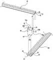
도 4는 본 발명에 따른 철판 적재용 스틸 파렛트의 주요부에 대한 분해 사시도이며,Figure 4 is an exploded perspective view of the main part of the steel pallet for loading steel plate according to the present invention,
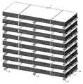
도 5는 본 발명에 따른 철판 적재용 스틸 파렛트를 다단으로 적재한 상태를 보여주는 사시도이다.Figure 5 is a perspective view showing a state in which the steel plate for loading steel pallets according to the present invention loaded in multiple stages.
< 도면의 주요부분에 대한 부호의 설명 ><Description of Symbols for Major Parts of Drawings>
10: 상판 11: 철부10: top plate 11: iron
12: 중간부 13: 주변부12: Middle 13: Peripheral
20: 하판 20: 요부20: Bottom 20: The main part
22: 중간부 23: 주변부22: middle portion 23: peripheral portion
30: 연결부재 31: 돌출부30: connecting member 31: protrusion
33: 돌출부33: protrusion
본 발명은 철판 적재용 스틸 파렛트에 관한 것으로, 특히 고하중에도 변형없이 안정적으로 사용할 수 있는 철판 적재용 스틸 파렛트에 관한 것이다.The present invention relates to a steel pallet for loading steel plates, and more particularly, to a steel pallet for loading steel plates that can be used stably without deformation even under high loads.
일반적으로 물품의 운반 및 보관을 위한 파렛트는 대개 일정한 두께나 폭을 갖는 목재를 격자 형태로 짜맞추어 그 교차 부위에 못과 같은 고정구를 이용하여 체결하는 형태로 구성되어진 것이 많이 이용되고 있으나, 위와 같은 목재로 제작된 파렛트는 그 자체 강도가 취약하고 사용수명이 짧은 문제점이 있다.In general, pallets for transporting and storing goods are generally used in the form of fastening wood having a certain thickness or width in the form of a lattice and fastening them using fasteners such as nails at their intersections. Pallets made of wood have problems of their own strength and short service life.
따라서, 위와 같은 목재 파렛트의 단점을 보완하기 위하여 금속재로 제작된 다양한 종류의 파렛트가 제안되면서 그 강도를 보강하여 사용수명이 연장되기는 하였으나, 파렛트의 위에 실리게 되는 적재물이 도 1에서 보는 바와 같이 소정의 넓이를 가지는 철판(1)인 경우에는 파렛트의 높이를 조정하는 간격유지구(2)가 취약하고, 또 상기 간격유지구(2)에 부착되는 상판(3)과 하판(4)의 연결구조가 취약하여 파렛트의 위에 다수매의 철판(1)이 실리면서 과도한 하중이나 충격 하중이 가해지게 되면, 그 하중을 감당하지 못하고 파렛트가 쉽게 변형되는 문제점이 있었다.Therefore, in order to compensate for the disadvantages of the wooden pallets as described above, various types of pallets made of metals have been proposed, but the service life of the pallets has been extended by reinforcing their strengths, but as shown in FIG. In the case of the iron plate (1) having a width of 2, the gap holding means for adjusting the height of the pallet is weak, and the connection structure of the upper plate (3) and the lower plate (4) attached to the gap holding hole (2) When the steel plate 1 is loaded on the pallet and the excessive load or the impact load is applied to the pallet, the pallet cannot be easily handled and the pallet is easily deformed.
더욱이, 다수매의 철판이 적재된 파렛트를 보관을 하고자 하는 경우에는 도 2에서 보는 바와 같이 다수매의 파렛트를 여러 개 적층시킨 상태에서 보관을 하게 되는데, 각각의 파렛트들은 약 50~100 매 이상의 철판(1)이 적재되기 때문에 최하측에 위치하는 파렛트의 간격유지구(2)들은 그 상측에 적층된 철판(1)의 전체 하중 즉, 약 30톤 이상의 하중이 가해지게 되므로 그 중량을 감당하지 못하고 상기 간격유지구(2)가 쉽게 변형을 하게 되고, 또 상판(3)과 하판(4) 역시 철판의 중량을 감 당하지 못하여 찌그러지게 되면서 상판(3) 위에 적재된 철판들이 파렛트를 벗어나게 되면서 안전 사고를 야기하게 되는 문제점이 있었다.In addition, if you want to store a pallet loaded with a large number of iron plates, as shown in Figure 2 is to be stored in a state in which a plurality of pallets are stacked, each pallet is about 50-100 sheets or more Since (1) is loaded, the
본 발명은 상기한 바와 같은 제반 문제점을 해결하기 위하여 안출된 것으로, 그 목적은 스틸 판재의 양을 적게 사용하면서도 고하중에도 변형없이 안정적으로 사용할 수 있는 철판 적재용 스틸 파렛트을 제공함에 있다.The present invention has been made to solve the above-mentioned problems, an object of the present invention is to provide a steel pallet for loading steel plate that can be used stably without deformation even while using a small amount of steel plate.
상기의 목적을 달성하기 위한 본 발명에 따른 철판 적재용 스틸 파렛트는 서로 이격져서 평행으로 배열되는 다수의 상판과, 상기 상판들과 직각을 이루도록 배치되는 다수의 하판들과, 상기 상판과 하판의 교차지점에 위치하여 상기 상판과 하판을 연결하는 다수의 연결부재로 이루어지는 철판 적재용 스틸 파렛트에 있어서, 상기 상판은, 판재를 길이방향으로 절곡하여 상측으로 돌출 형성되는 다수의 철부와, 상기 철부 사이에 위치하는 중간부와, 상기 철부의 양측에 형성되는 주변부로 이루어지고, 상기 하판은, 판재를 길이방향으로 절곡하여 하측으로 돌출 형성되는 다수의 요부와, 상기 요부 사이에 위치하는 중간부와, 상기 요부의 양측에 형성되는 주변부로 이루어지며, 상기 연결부재는, 상부측의 단부는, 그 상측에 위치하는 상판의 철부에 끼워지는 다수의 돌출부와, 상기 돌출부 사이에 형성되는 평판부로 이루어져, 상기 돌출부와 평판부의 상단은 상판의 하부면과 직접적으로 접촉이 이루어지며, 하부측의 단부는, 그 하측에 위치하는 하판의 요부에 끼워지는 다수의 돌출부와, 상기 돌출부 사이에 형성되는 평판부로 이루어져, 상기 돌출부와 평판부의 하단은 하판의 상부면과 직접적으로 접촉이 이루어지는 것을 특징으로 한다Steel pallet for loading the iron plate according to the present invention for achieving the above object is a plurality of top plates arranged in parallel spaced apart from each other, a plurality of bottom plates arranged to be perpendicular to the top plates, the intersection of the top plate and the bottom plate In the steel plate for loading steel pallet consisting of a plurality of connecting members for connecting the upper plate and the lower plate located at a point, the upper plate is a plurality of convex portions formed by bending the plate in the longitudinal direction protruding upwards, and between the iron portion The intermediate plate is located, and the peripheral portion formed on both sides of the convex portion, wherein the lower plate, a plurality of recesses formed to protrude downward by bending the plate in the longitudinal direction, the intermediate portion located between the recess, It consists of a peripheral part formed in both sides of a recessed part, The said connection member, The edge part of an upper side pinches in the convex part of the upper board located in the upper side. It consists of a plurality of protrusions and a flat plate formed between the protrusions, the upper end of the protrusions and the flat plate is in direct contact with the lower surface of the upper plate, the lower end of the lower plate is located in the recess of the lower plate Comprising a plurality of protrusions and a flat plate formed between the protrusions, the lower end of the protrusion and the flat plate is characterized in that the direct contact with the upper surface of the lower plate
여기서, 상기 연결부재는, 그 두께가 상기 상판과 하판의 두께보다도 2배 이상의 두께로 형성되는 것이 바람직하다.Here, it is preferable that the thickness of the said connection member is formed more than twice the thickness of the upper board and the lower board.
이하, 본 발명의 바람직한 실시예에 따른 철판 적재용 스틸 파렛트를 첨부 도면에 의거하여 상세히 설명하면 다음과 같다.Hereinafter, with reference to the accompanying drawings, a steel pallet for mounting a steel sheet according to a preferred embodiment of the present invention in detail as follows.
본 발명에 따른 철판 적재용 스틸 파렛트는 도 3에서 보는 바와 같이 서로 이격져서 평행으로 배열되는 다수의 상판(10)과, 상기 상판(10)들과 직각을 이루도록 배치되는 다수의 하판(20)들과, 상기 상판(10)과 하판(20)의 교차지점에 위치하여 상기 상판(10)과 하판(20)을 연결하는 다수의 연결부재(30)로 이루어진다.Steel pallet for loading iron plate according to the invention is a plurality of
상기 상판(10)은, 도 3 및 도 4에서 보는 바와 같이 판재를 길이방향으로 절곡하여 상측으로 돌출 형성되는 다수의 철부(11)와, 상기 철부(11) 사이에 위치하는 중간부(12)와, 상기 철부(11)의 양측에 형성되는 주변부(13)로 이루어진다.3 and 4, the
상기 하판(20)은 판재를 길이방향으로 절곡하여 하측으로 돌출 형성되는 다수의 요부(21)와, 상기 요부(21) 사이에 위치하는 중간부(22)와, 상기 요부(21)의 양측에 형성되는 주변부(23)로 이루어진다.The
상기 연결부재(30)는, 상기 상판(10)이 지면과 일정간격 만큼 이격지도록 하면서 상기 상판(10)을 그 하부에 위치하는 하판(20)과 연결되도록 하여 지게차의 포크가 상기 이격되는 공간에 삽입될 수 있도록 하기 위한 부재로서, 그 상부측의 단부는 그 상측에 위치하는 상판(10)의 철부(11)에 끼워지는 다수의 돌출부(31)와, 상기 돌출부(31) 사이에 형성되는 평판부로 이루어진다.The connecting
상기 평판부는 상기 상판(10)의 길이방향과 평행으로 형성되는 제1평판부(32a)와, 상기 제1평판부(32a)와 직각으로 형성되면서 상기 돌출부(21)의 사이에 위치하는 제2평판부(32b)로 이루어지며, 상기 제1평판부(32a)와 제2평판부(32b)와 돌출부(31)의 상단은 모두 상기 상판(10)과 조립이 이루어졌을 때, 상기 상판(10)의 하부면과 직접적으로 접촉이 이루어지게 된다.The flat plate portion is formed between the first
또한, 상기 연결부재(30)의 하부측의 단부는 그 하측에 위치하는 하판(20)의 요부(21)에 끼워지는 다수의 돌출부(33)와, 상기 돌출부(33) 사이에 형성되는 평판부로 이루어진다.In addition, an end portion of the lower side of the connecting
상기 평판부는 상기 하판(20)의 길이방향과 평행으로 형성되는 제1평판부(34a)와, 상기 제1평판부(34a)와 직각으로 형성되면서 상기 돌출부(33)의 사이에 위치하는 제2평판부(34b)로 이루어지며, 상기 제1평판부(34a)와 제2평판부(34b)와 돌출부(33)의 하단은 모두 상기 하판(20)과 조립이 이루어졌을 때, 상기 하판(20)의 상부면과 직접적으로 접촉이 이루어지게 된다.The flat plate portion is formed between the first
한편, 상기 연결부재(30)는, 도 5에서 보는 바와 같이 파렛트를 다수매 적층하여 야적장에 적치하여 보관하고자 하는 경우에는 최하측에 위치하는 파렛트의 경우 그 상측에 위치하는 파렛트보다도 하중의 부담이 보다 커지게 되므로 이러한 경우에는 파렛트의 강도가 보다 더 증대되어야 할 필요가 있다.On the other hand, the connecting
따라서, 파렛트의 강도를 증대시키도록 하기 위해서는 상판(10)과 하판(20)의 수를 늘리는 방법이나 연결부재(30)의 수를 늘리는 방법 등 여러 가지의 방법들이 강구될 수 있다.Accordingly, in order to increase the strength of the pallet, various methods such as increasing the number of the
그러나, 위와 같은 방법들은 단편적으로는 파렛트의 강도를 증대시킬 수는 있으나, 그 일면으로는 파렛트의 무게가 보다 커지게 되므로, 보다 효율적인 방법이 강구되어야 하며, 그러한 방법들 중의 하나로서 상판(10)과 하판(20)과 달리 연결부재(30)의 두께를 달리하는 것이 스틸판재를 보다 적게 사용하게 되므로 파렛트의 전체 중량을 감소시킬 수 있게 된다.However, the above methods can increase the strength of the pallet in part, but since the weight of the pallet becomes larger on one side, a more efficient method should be devised, and as one of the methods, the
위와 같은 경우 상판(10)과 하판(20)의 두께를 1.5t로 하면서 연결부재(30)의 두께를 3.2t로 하는 경우 도 5에서 보는 바와 같이 철판을 모두 8단으로 적재하여 총 중량이 30톤에 이르는 경우에도 최하층의 파렛트는 전혀 변형되거나 손상되지 않았다. 따라서, 연결부재(30)의 두께는 상판(10)과 하판(20)의 두께보다도 2 배 이상으로 하는 것이 바람직하다는 것을 알 수 있었다.In the above case, when the thickness of the
위와 같은 구성을 가지는 본 발명에 따른 철판 적재용 스틸 파렛트는 상판(10)과 연결부재(30)를 연결함에 있어서, 상판(10)의 하부면과 연결부재(30)의 상단이 모두 그 외주를 따라서 직접적으로 접촉이 이루어지도록 되어 있고, 또 하판(20)과 연결부재(30)를 연결함에 있어서, 하판(20)의 상부면과 연결부재(30)의 하단이 모두 그 외주를 따라서 직접적으로 접촉이 이루어지도록 되어 있으므로 상판(10)의 상부쪽에 적재된 하중이 과도하거나 또는 충격하중이 가해진다 하더라도 상판(10)과 하판(20) 사이에 직접적으로 접촉하는 연결부재(30)가 상기 하중을 직접적으로 흡수하게 되므로 수직하중을 충분히 견디고 함몰을 방지할 수가 있게 되며, 더욱이 상기 연결부재(30)의 두께가 상판(10)이나 하판(20)보다 두껍게 형성되어 있기 때문에 전체적인 스틸판재의 양을 적게 사용하면서도 효율적이고 가벼워서 보강된 적재구조를 가지며, 보다 더 안정적으로 파렛트의 변형을 방지할 수가 있게 된다.Steel pallet for loading steel plate according to the present invention having the configuration as described above in connecting the
이상에서 살펴본 바와 같이 본 발명에 따른 철판 적재용 스틸 파렛트는 스틸판재의 양을 적게 사용하면서도 고하중에도 변형없이 안정적으로 사용할 수가 있게 된다.As described above, the steel pallet for loading a steel sheet according to the present invention can be used stably without deformation even under high loads while using a small amount of steel sheet.
본 발명은 첨부된 도면에 도시된 실시예들을 기준하여 설명되어 있으나 이는 예시적인 것이라 할 수 있고, 당해 기술 분야에서 통상의 지식을 가진 자라면 이로부터 다양한 변형 및 균등한 실시예 들을 생각해 낼 수 있으므로 이러한 균등한 실시예 들 또한 본 발명의 특허청구범위 내에 포함하는 것으로 보아야 한다.Although the present invention has been described with reference to the embodiments illustrated in the accompanying drawings, this may be regarded as exemplary, and a person skilled in the art may conceive various modifications and equivalent embodiments therefrom. Such equivalent embodiments should also be considered to be within the scope of the claims of the present invention.
Claims (2)
Translated fromKoreanPriority Applications (1)
| Application Number | Priority Date | Filing Date | Title |
|---|---|---|---|
| KR1020060068272AKR100824668B1 (en) | 2006-07-21 | 2006-07-21 | Steel pallets for steel plate loading |
Applications Claiming Priority (1)
| Application Number | Priority Date | Filing Date | Title |
|---|---|---|---|
| KR1020060068272AKR100824668B1 (en) | 2006-07-21 | 2006-07-21 | Steel pallets for steel plate loading |
Publications (2)
| Publication Number | Publication Date |
|---|---|
| KR20080008706A KR20080008706A (en) | 2008-01-24 |
| KR100824668B1true KR100824668B1 (en) | 2008-04-24 |
Family
ID=39221474
Family Applications (1)
| Application Number | Title | Priority Date | Filing Date |
|---|---|---|---|
| KR1020060068272AExpired - Fee RelatedKR100824668B1 (en) | 2006-07-21 | 2006-07-21 | Steel pallets for steel plate loading |
Country Status (1)
| Country | Link |
|---|---|
| KR (1) | KR100824668B1 (en) |
Citations (6)
| Publication number | Priority date | Publication date | Assignee | Title |
|---|---|---|---|---|
| KR200188847Y1 (en)* | 2000-01-31 | 2000-07-15 | 주식회사태경파레트 | A plate for an iron material palette |
| KR200278659Y1 (en)* | 2002-03-29 | 2002-06-20 | 코리아에스피엔피 주식회사 | A palette for a goods packing |
| KR200279654Y1 (en) | 2002-04-04 | 2002-06-24 | (주) 나노텍 | Supports for steel pallet |
| KR200325402Y1 (en)* | 2003-04-23 | 2003-09-03 | 최종혜 | A iron pallet for for carring cargo |
| KR20030085303A (en) | 2002-04-30 | 2003-11-05 | 주식회사 코리아코프 | Flat metal pallet |
| JP2004142829A (en)* | 2002-08-27 | 2004-05-20 | Yamahashi Kogyo Kk | Pallet for transportation |
- 2006
- 2006-07-21KRKR1020060068272Apatent/KR100824668B1/ennot_activeExpired - Fee Related
Patent Citations (6)
| Publication number | Priority date | Publication date | Assignee | Title |
|---|---|---|---|---|
| KR200188847Y1 (en)* | 2000-01-31 | 2000-07-15 | 주식회사태경파레트 | A plate for an iron material palette |
| KR200278659Y1 (en)* | 2002-03-29 | 2002-06-20 | 코리아에스피엔피 주식회사 | A palette for a goods packing |
| KR200279654Y1 (en) | 2002-04-04 | 2002-06-24 | (주) 나노텍 | Supports for steel pallet |
| KR20030085303A (en) | 2002-04-30 | 2003-11-05 | 주식회사 코리아코프 | Flat metal pallet |
| JP2004142829A (en)* | 2002-08-27 | 2004-05-20 | Yamahashi Kogyo Kk | Pallet for transportation |
| KR200325402Y1 (en)* | 2003-04-23 | 2003-09-03 | 최종혜 | A iron pallet for for carring cargo |
Also Published As
| Publication number | Publication date |
|---|---|
| KR20080008706A (en) | 2008-01-24 |
Similar Documents
| Publication | Publication Date | Title |
|---|---|---|
| US6041719A (en) | Material handling pallet | |
| US20070245932A1 (en) | Metal pallet | |
| US7878127B2 (en) | Pallet with optimized cargo layer and related methods | |
| KR20100094502A (en) | Loading pallet | |
| KR20060083088A (en) | Cargo loading pallet | |
| KR101115606B1 (en) | Structure for reinforcing strength in pallet | |
| KR101498945B1 (en) | Aluminium pallet | |
| KR100824668B1 (en) | Steel pallets for steel plate loading | |
| US11267611B2 (en) | Pallet for carrying a load | |
| US20080011205A1 (en) | Nestable Load Support | |
| KR200400826Y1 (en) | Pallet | |
| KR102480498B1 (en) | Palette of disassembling and assembling easily | |
| US11840370B2 (en) | Shock absorbing pallet deck and related methods | |
| JP7355383B2 (en) | palette | |
| KR100644760B1 (en) | Steel pallets for steel plate loading | |
| KR200413675Y1 (en) | Steel pallet | |
| KR200191394Y1 (en) | A member used in a palette | |
| JPS62235055A (en) | Flat pallet | |
| KR20070114870A (en) | Cargo loading pallet | |
| KR100709791B1 (en) | Steel pallets for steel plate loading | |
| KR100635477B1 (en) | Cargo loading pallet | |
| WO2020008394A1 (en) | Pallet | |
| KR200409050Y1 (en) | Paper pallets | |
| KR100340558B1 (en) | Steel pallet and manufacturing method thereof | |
| KR100699358B1 (en) | Paper Palette |
Legal Events
| Date | Code | Title | Description |
|---|---|---|---|
| A201 | Request for examination | ||
| PA0109 | Patent application | St.27 status event code:A-0-1-A10-A12-nap-PA0109 | |
| PA0201 | Request for examination | St.27 status event code:A-1-2-D10-D11-exm-PA0201 | |
| D13-X000 | Search requested | St.27 status event code:A-1-2-D10-D13-srh-X000 | |
| D14-X000 | Search report completed | St.27 status event code:A-1-2-D10-D14-srh-X000 | |
| E902 | Notification of reason for refusal | ||
| PE0902 | Notice of grounds for rejection | St.27 status event code:A-1-2-D10-D21-exm-PE0902 | |
| P11-X000 | Amendment of application requested | St.27 status event code:A-2-2-P10-P11-nap-X000 | |
| P13-X000 | Application amended | St.27 status event code:A-2-2-P10-P13-nap-X000 | |
| PG1501 | Laying open of application | St.27 status event code:A-1-1-Q10-Q12-nap-PG1501 | |
| E701 | Decision to grant or registration of patent right | ||
| PE0701 | Decision of registration | St.27 status event code:A-1-2-D10-D22-exm-PE0701 | |
| GRNT | Written decision to grant | ||
| PR0701 | Registration of establishment | St.27 status event code:A-2-4-F10-F11-exm-PR0701 | |
| PR1002 | Payment of registration fee | St.27 status event code:A-2-2-U10-U11-oth-PR1002 Fee payment year number:1 | |
| PG1601 | Publication of registration | St.27 status event code:A-4-4-Q10-Q13-nap-PG1601 | |
| PN2301 | Change of applicant | St.27 status event code:A-5-5-R10-R11-asn-PN2301 | |
| R18-X000 | Changes to party contact information recorded | St.27 status event code:A-5-5-R10-R18-oth-X000 | |
| PN2301 | Change of applicant | St.27 status event code:A-5-5-R10-R11-asn-PN2301 | |
| PN2301 | Change of applicant | St.27 status event code:A-5-5-R10-R11-asn-PN2301 | |
| PN2301 | Change of applicant | St.27 status event code:A-5-5-R10-R14-asn-PN2301 | |
| P14-X000 | Amendment of ip right document requested | St.27 status event code:A-5-5-P10-P14-nap-X000 | |
| P16-X000 | Ip right document amended | St.27 status event code:A-5-5-P10-P16-nap-X000 | |
| Q16-X000 | A copy of ip right certificate issued | St.27 status event code:A-4-4-Q10-Q16-nap-X000 | |
| R18-X000 | Changes to party contact information recorded | St.27 status event code:A-5-5-R10-R18-oth-X000 | |
| PR1001 | Payment of annual fee | St.27 status event code:A-4-4-U10-U11-oth-PR1001 Fee payment year number:4 | |
| PR1001 | Payment of annual fee | St.27 status event code:A-4-4-U10-U11-oth-PR1001 Fee payment year number:5 | |
| FPAY | Annual fee payment | Payment date:20130401 Year of fee payment:6 | |
| PR1001 | Payment of annual fee | St.27 status event code:A-4-4-U10-U11-oth-PR1001 Fee payment year number:6 | |
| FPAY | Annual fee payment | Payment date:20140402 Year of fee payment:7 | |
| PR1001 | Payment of annual fee | St.27 status event code:A-4-4-U10-U11-oth-PR1001 Fee payment year number:7 | |
| PR1001 | Payment of annual fee | St.27 status event code:A-4-4-U10-U11-oth-PR1001 Fee payment year number:8 | |
| P14-X000 | Amendment of ip right document requested | St.27 status event code:A-5-5-P10-P14-nap-X000 | |
| FPAY | Annual fee payment | Payment date:20160225 Year of fee payment:9 | |
| PR1001 | Payment of annual fee | St.27 status event code:A-4-4-U10-U11-oth-PR1001 Fee payment year number:9 | |
| PN2301 | Change of applicant | St.27 status event code:A-5-5-R10-R13-asn-PN2301 St.27 status event code:A-5-5-R10-R11-asn-PN2301 | |
| FPAY | Annual fee payment | Payment date:20170308 Year of fee payment:10 | |
| PR1001 | Payment of annual fee | St.27 status event code:A-4-4-U10-U11-oth-PR1001 Fee payment year number:10 | |
| P22-X000 | Classification modified | St.27 status event code:A-4-4-P10-P22-nap-X000 | |
| FPAY | Annual fee payment | Payment date:20180409 Year of fee payment:11 | |
| PR1001 | Payment of annual fee | St.27 status event code:A-4-4-U10-U11-oth-PR1001 Fee payment year number:11 | |
| PR1001 | Payment of annual fee | St.27 status event code:A-4-4-U10-U11-oth-PR1001 Fee payment year number:12 | |
| PR1001 | Payment of annual fee | St.27 status event code:A-4-4-U10-U11-oth-PR1001 Fee payment year number:13 | |
| PC1903 | Unpaid annual fee | St.27 status event code:A-4-4-U10-U13-oth-PC1903 Not in force date:20210418 Payment event data comment text:Termination Category : DEFAULT_OF_REGISTRATION_FEE | |
| PC1903 | Unpaid annual fee | St.27 status event code:N-4-6-H10-H13-oth-PC1903 Ip right cessation event data comment text:Termination Category : DEFAULT_OF_REGISTRATION_FEE Not in force date:20210418 |