KR100823531B1 - Multi-Drive Driver Control - Google Patents
Multi-Drive Driver ControlDownload PDFInfo
- Publication number
- KR100823531B1 KR100823531B1KR1020070037249AKR20070037249AKR100823531B1KR 100823531 B1KR100823531 B1KR 100823531B1KR 1020070037249 AKR1020070037249 AKR 1020070037249AKR 20070037249 AKR20070037249 AKR 20070037249AKR 100823531 B1KR100823531 B1KR 100823531B1
- Authority
- KR
- South Korea
- Prior art keywords
- panel
- driving
- terminal block
- button
- acb
- Prior art date
- Legal status (The legal status is an assumption and is not a legal conclusion. Google has not performed a legal analysis and makes no representation as to the accuracy of the status listed.)
- Expired - Fee Related
Links
Images


Classifications
- G—PHYSICS
- G05—CONTROLLING; REGULATING
- G05B—CONTROL OR REGULATING SYSTEMS IN GENERAL; FUNCTIONAL ELEMENTS OF SUCH SYSTEMS; MONITORING OR TESTING ARRANGEMENTS FOR SUCH SYSTEMS OR ELEMENTS
- G05B19/00—Programme-control systems
- G05B19/02—Programme-control systems electric
- G05B19/04—Programme control other than numerical control, i.e. in sequence controllers or logic controllers
- G—PHYSICS
- G05—CONTROLLING; REGULATING
- G05B—CONTROL OR REGULATING SYSTEMS IN GENERAL; FUNCTIONAL ELEMENTS OF SUCH SYSTEMS; MONITORING OR TESTING ARRANGEMENTS FOR SUCH SYSTEMS OR ELEMENTS
- G05B23/00—Testing or monitoring of control systems or parts thereof
- G05B23/02—Electric testing or monitoring
- G05B23/0205—Electric testing or monitoring by means of a monitoring system capable of detecting and responding to faults
- G05B23/0259—Electric testing or monitoring by means of a monitoring system capable of detecting and responding to faults characterized by the response to fault detection
- G05B23/0267—Fault communication, e.g. human machine interface [HMI]
- G05B23/027—Alarm generation, e.g. communication protocol; Forms of alarm
- H—ELECTRICITY
- H02—GENERATION; CONVERSION OR DISTRIBUTION OF ELECTRIC POWER
- H02H—EMERGENCY PROTECTIVE CIRCUIT ARRANGEMENTS
- H02H3/00—Emergency protective circuit arrangements for automatic disconnection directly responsive to an undesired change from normal electric working condition with or without subsequent reconnection ; integrated protection
- H02H3/02—Details
- H02H3/04—Details with warning or supervision in addition to disconnection, e.g. for indicating that protective apparatus has functioned
Landscapes
- Engineering & Computer Science (AREA)
- Physics & Mathematics (AREA)
- General Physics & Mathematics (AREA)
- Automation & Control Theory (AREA)
- Human Computer Interaction (AREA)
- Control Of Multiple Motors (AREA)
Abstract
Translated fromKoreanDescription
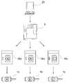
Translated fromKorean도 1는 본 발명에 의한 제어장치가 설치된 구성도1 is a configuration diagram installed control device according to the present invention
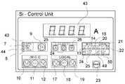
도 2은 본 발명에 의한 데스크판넬 제어장치의 제어판 전면부 구성도2 is a front view of the control panel of the desk panel control apparatus according to the present invention
도 3는 본 발명에 의한 엠씨씨판넬 제어장치의 제어판 전면부 구성도Figure 3 is a control panel front panel configuration of the MC panel control apparatus according to the present invention
도 4는 본 발명에 의한 엠씨씨판넬 제어장치의 제어판 후면부 구성도Figure 4 is a control panel rear panel configuration of the MC panel control apparatus according to the present invention
도 5은 본 발명에 의한 데스크판넬 제어장치의 제어흐름도5 is a control flow chart of the desk panel control apparatus according to the present invention
도 6은 본 발명에 의한 엠씨씨판넬 제어장치의 제어흐름도6 is a control flow chart of the MC panel control apparatus according to the present invention
도 7은 본 발명에 의한 로컬판넬 제어장치의 제어흐름도7 is a control flowchart of a local panel control apparatus according to the present invention;
<도면의 주요부분에 대한 부호의 설명><Description of the symbols for the main parts of the drawings>
1a, 1b, 1c : 구동소자 2a, 2b, 2c : 엠씨씨판넬(종래)1a, 1b, 1c: driving elements 2a, 2b, 2c: MC panel (conventional)
3 : 엠씨씨판넬 44 : 구동방식 전환스위치부3: MC panel 44: drive type switching switch
5 : 엠씨씨판넬 제어판 6 : 데이터 표시부5: MC panel control panel 6: Data display unit
7 : 엠씨씨판넬 운전모드 램프 8 : 로컬판넬 운전모드 램프7: MC panel operation mode lamp 8: Local panel operation mode lamp
9 : 운전모드 선택버튼 10 : 엠씨씨판넬 정회전 운전버튼9: operation mode selection button 10: MC panel forward rotation operation button
11 : 엠씨씨판넬 운전정지 버튼 12 : 엠씨씨판넬 역회전 운전버튼11: MC panel operation stop button 12: MC panel reverse rotation operation button
13 : 엠씨씨판넬 정회전 운전모드 표시 램프 14 : 엠씨씨판넬 운전정지모드 표시 램프13: MC panel forward rotation operation mode display lamp 14: MC panel operation stop mode display lamp
15 : 엠씨씨판넬 역회전 운전모드 표시 램프 16a, 16b, 16c : 로컬판넬15: MC panel reverse operation
17 : 로컬판넬 정회전 운전모드 버튼 18 : 로컬판넬 운전 정지모드 버튼17: Local panel forward run mode button 18: Local panel run stop mode button
19 : 로컬판넬 역회전 운전모드 버튼 20 : 로컬판넬 정회전 운전모드 표시램프19: Local panel reverse run mode button 20: Local panel forward run mode display lamp
21 : 로컬판넬 운전정지 표시램프 22 : 로컬판넬 역회전 운전모드 표시램프21: Local panel operation stop display lamp 22: Local panel reverse rotation operation mode display lamp
23 : 전자과전류릴레이 리셋(RESET)버튼23: Electronic over current relay reset button
24 : 전자과전류릴레이(EOCR)의 고장상태 표시램프24: Fault status display lamp of electronic over current relay (EOCR)
25 : 전동기동회로 전류 설정상태 표시 램프 26 : 데스크판넬25: lamp for electric current setting status 26: desk panel
27 : 통신 모드 설정 버튼 28 : 통신번호 업(UP) 버튼27: communication mode setting button 28: communication number UP button
29 : 통신번호 다운(DOWN) 버튼 30~44 : 엠씨씨판넬 후면부 구성요소29: Communication number down
45 : 중앙정보처리부 46 : 자동구동운전모드 램프45: central information processor 46: automatic drive operation mode lamp
47 : 데스크판넬 운전모드 램프 48 : 데스크판넬 제어판47: desk panel operation mode lamp 48: desk panel control panel
본 발명은 다종 구동소자 제어장치에 관한 것으로, 하나의 엠씨씨 판넬로서 이에 연결된 여러 종류의 구동소자를 용이하게 구동할 수 있게 함으로써 구성을 간소화시켜 효율적으로 사용할 수 있도록 함은 물론 구동비용을 절감하기 위한 다종 구동소자 제어장치에 관한 것이다.The present invention relates to a control device for a variety of drive devices, and as a single MC panel, it is possible to easily drive a variety of drive devices connected to it to simplify the configuration and to efficiently use as well as to reduce the driving cost It relates to a multi-driving device control device for.
산업현장의 여러 곳에는 모터 등과 같은 구동소자와 함께 로컬판넬(Local Panel)이 설치되고, 그 현장의 기계실이나 전기실에는 상기 구동소자를 제어하는 배전반의 일종인 엠씨씨 판넬(MCC Panel : Motor Control Center)이 설치되며, 중앙통제실에는 데스크 판넬(De나 Panel)이 설치된 구조로 되어 있는 것으로, 상기 각 판넬은 유선으로 제어되거나 무선으로 원격제어되는데, 중앙통제실인 데스크 판넬에서 명령을 내리게 되면 엠씨씨 판넬을 거쳐서 각 로컬판넬에 연결된 구동소자를 명령에 따라 구동시키게 되는 것이다.Local panels are installed in various places of the industrial site along with driving devices such as motors, and the MCC panel (MCC Panel), which is a kind of switchboard for controlling the driving devices, is installed in the machine room or the electric room of the site. ) Is installed, and the central control room has a desk panel (De or Panel) is installed, each panel is wired or wirelessly controlled remotely, when the command from the central control room desk panel MC panel Through the driving device connected to each local panel will be driven according to the command.
구동방식이 각각 다른 여러 개의 구동소자와 함께 현장의 여러 곳에 설치된 로컬 판넬(Local Panel), 상기 로컬 판넬(Local Panel)과 연결되어 구동소자들을 제어할 수 있는 엠씨씨 판넬(MCC Panel : Motor Control Center), 상기 엠씨씨 판넬(MCC Panel : Motor Control Center)과 로컬 판넬(Local Panel)을 제어하는 것으로 중앙통제실에 설치되는 데스크 판넬(Desk Panel)로써 구동소자의 구동시스템이 이루어진다.MCC Panel (MCC Panel) that can control the driving devices connected to the local panel (Local Panel) and the local panel (Local Panel) installed in several places of the site with a plurality of driving devices each having a different driving method ), The MC panel (MCC Panel: Motor Control Center) and the local panel (Local Panel) by controlling the driving system of the drive device as a desk panel (Desk Panel) installed in the central control room.
예를 들어, 정수장 같은 경우에는 수문을 열 때 동작하는 모터와, 물을 끌어올리는 양수기 모터 등이 구비되고, 상기 모터와 같은 구동소자의 구동을 제어하는 수배전반의 일종이 바로 엠씨씨 판넬이다.For example, in the case of a water purification plant, a motor that operates when a water gate is opened, a water pump motor that raises water, and the like are provided, and a type of switchgear that controls driving of a driving element such as the motor is an MC panel.
엠씨씨 판넬에 의해 구동이 제어되는 구동소자는 동일한 기능을 가진 구동소자라 하더라도 출력이나 용도에 따라 그 구동방식이 각각 달리하게 되는데, 그 구동방식의 종류로는 직입 기동, 리액터 기동, 정/역 기동, 와이-델타 기동 등이 있으며, 각 구동방식에 적합한 엠씨씨 판넬이 별도로 구비되어야 구동방식을 달리하는 각 구동소자를 구동시킬 수 있게 되는 것이다.The driving device controlled by the MC panel has different driving methods depending on the output and the use, even if the driving device has the same function.The types of the driving methods are direct start, reactor start, and forward / reverse. There are starting, Y-delta, etc., and the MC panel suitable for each driving method must be separately provided to drive each driving device that changes the driving method.
산업현장에는 보통 상기와 같이 구동방식을 달리하는 각 구동소자들을 설치되어 있는데, 각 구동소자를 구동시키기 위해서는 각 구동소자에 맞는 별도의 엠씨씨 판넬들을 구비하여야 했으며 실제로 전기실이나 기계실에 다수의 엠씨씨 판넬들을 구비하다보면 유지 비용이 많이 소요되고, 대단히 복잡하다는 문제점이 있다.In the industrial field, each driving device having a different driving method is installed as described above. In order to drive each driving device, it is necessary to provide separate MC panels for each driving device. When the panels are provided, there is a problem in that the maintenance cost is very high and is very complicated.
본 발명은 상기와 같은 문제점을 해결하기 위해 안출한 것으로, 하나의 엠씨씨 판넬로서 이에 연결된 여러 종류의 구동소자를 용이하게 구동할 수 있게 함으로써 구성을 간소화시켜 효율적으로 사용할 수 있도록 함은 물론 구동비용을 절감하기 위한 목적이 있다.The present invention has been made to solve the above problems, it is possible to easily drive a variety of drive elements connected to it as a single MC panel to simplify the configuration to be used efficiently as well as driving cost The purpose is to reduce costs.
이를 위해, 본 발명은 다양한 구동방식을 구동시키는 각 집적회로들을 하나의 엠씨씨 판넬에 집약시키고 구동방식 전환스위치부로서 구동방식을 전환시킬 수 있도록 함으로써, 하나의 엠씨씨 판넬로도 여러 구동방식의 구동소자를 구동시킬 수 있게 된 다종 구동소자 제어장치를 제공하고자 하며, 발명의 구성에서 보다 상세하게 설명하고자 한다.To this end, the present invention is to aggregate the integrated circuits for driving the various drive method in one MC panel and to be able to switch the drive method as the drive mode switching switch unit, so that even one MC panel It is intended to provide a multiple driving device control device capable of driving a driving device, and will be described in more detail in the configuration of the invention.
상기와 같은 목적을 달성하기 위해 본 발명을 첨부도면에 의거하여 보다 상세하게 설명하면 다음과 같다.In order to achieve the above object, the present invention will be described in more detail based on the accompanying drawings.
도 1는 본 발명에 의한 제어장치가 설치된 구성도, 도 2은 본 발명에 의한 데스크판넬 제어장치의 제어판 전면부 구성도, 도 3는 본 발명에 의한 엠씨씨판넬 제어장치의 제어판 전면부 구성도, 도 4는 본 발명에 의한 엠씨씨판넬 제어장치의 제어판 후면부 구성도, 도 5은 본 발명에 의한 데스크판넬 제어장치의 제어흐름도, 도 6은 본 발명에 의한 엠씨씨판넬 제어장치의 제어흐름도, 도 7은 본 발명에 의한 로컬판넬 제어장치의 제어흐름도로서, 본 발명은 구동소자 제어장치에 있어서, 현장에 설치된 여러 구동소자(1a, 1b, 1c)들의 구동방식이 각각 다르더라도 각각의 구동방식에 맞추어 별도의 엠씨씨판넬(2a, 2b, 2c)(MCC panel : Motor Control Center)을 구비할 필요없이 하나의 엠씨씨 판넬(MCC Panel)(3)만으로도 구동가능하다는 데에 특징이 있는 것으로, 이를 위해 본 발명은 여러 구동소자(1a, 1b, 1c)를 구동할 수 있는 집적회로를 하나의 엠씨씨판넬(3)에 집약시키고 상기 엠씨씨판넬(3)에 구동방식 전환스위치부(44)를 형성하여 상기 구동방식 전환스위치부(44)를 구동하고자 하는 구동소자(1a, 1b, 1c)의 구동방식에 맞추어 설정하게 되면 다양한 구동방식으로 구동되는 구동소자(1a, 1b, 1c)들은 하나의 엠씨씨판넬(3)로 구동가능하게 구성한 것이다.1 is a configuration diagram in which the control device according to the present invention is installed, FIG. 2 is a front view of a control panel front part of a desk panel control device according to the present invention, and FIG. 3 is a front view of a control panel front part of an MC panel control device according to the present invention. 4 is a block diagram of a control panel rear part of the MC panel control apparatus according to the present invention, FIG. 5 is a control flow diagram of the desk panel control apparatus according to the present invention, FIG. 6 is a control flow diagram of the MC panel control apparatus according to the present invention. 7 is a control flow chart of a local panel control apparatus according to the present invention, the present invention is a drive element control device, even if the driving method of the various drive elements (1a, 1b, 1c) installed in the field is different, respectively, each driving method It is characterized by being able to be driven by only one MC panel (MCC Panel) 3 without having to provide separate MC panels (2a, 2b, 2c) (MCC panel: Motor Control Center). Seen for this Myung has integrated integrated circuits capable of driving
이를 보다 상세하게 설명하면, 도 4의 엠씨씨 판넬 제어판(5) 전면부의 구성도에 도시된 바와 같이, 입력되는 데이터나 수치가 표시되는 데이터 표시부(6), 엠씨씨판넬 운전모드 램프(7), 로컬판넬 운전모드 램프(8)가 형성되어 있고, 상기 2가지 운전모드 중 하나를 선택할 수 있는 운전모드 선택 버튼(9)이 형성되어 있으며, 엠씨씨판넬(3)에서 구동소자(1a, 1b, 1c)를 구동할 수 있는 정회전 운전 버튼(10), 운전 정지버튼(11), 역회전 운전 버튼(12)과 함께, 정회전 운전모드 표시 램프(13), 운전정지 모드 표시 램프(14), 역회전 운전모드 표시 램프(15)가 형성되어 있다.More specifically, as shown in the configuration of the MC panel control panel 5 of FIG. 4, the data display unit 6 and the MC panel
또한, 로컬판넬(16a, 16b, 16c)의 정회전 운전모드 버튼(17)이 운전정지버튼(18), 역회전 운전모드 버튼(19)과 함께 형성되어 있고, 이와 함께 로컬판넬(16a, 16b, 16c)의 정회전 운전모드 표시 램프(20), 운전정지 모드 표시 램프(21), 역회전 운전모드 표시 램프(22)가 형성되어 있다.In addition, the forward rotation
또한, 엠씨씨판넬(3)에서 전자과전류릴레이(EOCR : Electronic Overload Relays)의 리셋팅(Resetting)을 위한 리셋(Reset) 버튼(23), 구동소자(1a, 1b, 1c)의 전자과전류릴레이(EOCR)의 고장상태 표시램프(24), 전자과전류릴레이(EOCR) 전류가 설정상태임을 표시하기 위한 전동기동회로 전류 설정상태 표시 램프(25)가 형성되어 있다.In addition, the
또한, 하나의 중앙통제부 아래에 두 개의 현장이 있을 경우, 각 현장에는 엠 씨씨판넬(3)이 하나씩 설치되며, 이 경우, 하나의 데스크 판넬(26)로 두 개의 엠씨씨판넬(3)을 제어할 경우 특정 엠씨씨판넬(3)과 통신하기 위한 통신 모드 설정 버튼(27), 상기 통신 모드를 설정할 때 통신번호를 선택하는 업(UP)버튼(28), 통신번호를 선택하는 다운(DOWN)버튼(29)과 함께 형성되어 있다.In addition, when there are two sites under one central control unit, one
상기와 같이 전면부가 형성된 엠씨씨 판넬(3)의 후면부는 도 5에 도시된 바와 같이, 외부로부터의 전자과전류릴레이(EOCR)의 고장상태를 입력받기 위한 단자대(30), 공기전기차단기(ACB : Air Circuit Breaker) / 진공전기차단기(VCB : Vacuum Circuit Breaker) 의 켜짐(ON)상태를 입력받기 위한 단자대(31), 공기전기차단기(ACB) / 진공전기차단기(VCB)의 꺼짐(OFF)상태를 입력받기 위한 단자대(32), 공기전기차단기(ACB) / 진공전기차단기(VCB)의 과전류 계전기(OCR)의 고장상태를 입력받기 위한 단자대(33), 공기전기차단기(ACB) / 진공전기차단기(VCB)의 과전류 지락계전기(OCGR)의 고장상태를 입력받기 위한 단자대(34), 구동소자(1a, 1b, 1c) 구동을 위한 출력 A의 접점을 출력하기 위한 단자대(35), 구동소자(1a, 1b, 1c) 구동을 위한 출력 B의 접점을 출력하기 위한 단자대(36), 구동소자(1a, 1b, 1c) 구동을 위한 출력 C의 접점을 출력하기 위한 단자대(37), 공기전기차단기(ACB) / 진공전기차단기(VCB)의 켜짐(ON)제어의 접점을 출력하기 위한 단자대(38), 공기전기차단기(ACB) / 진공전기차단기(VCB)의 꺼짐(OFF)제어의 접점을 출력하기 위한 단자대(39), 공기전기차단기(ACB) / 진공전기차단기(VCB)의 과전류 계전기(OCR)의 고장상태의 접점을 출력하기 위한 단자대(40), 공기전기차단기(ACB) / 진공전기차단기(VCB)의 과전류 지락계전기(OCGR)의 고장상태의 접점을 출력하기 위한 단자대(41), 구동전원 입력을 위한 단자대(42), 구동소자(1a, 1b, 1c)의 전류값을 측정하기 위한 계기용 변류기(CT : Current Transformer)연결 단자대(43), 특히, 여러 구동방식으로 된 구동소자(1a, 1b, 1c)를 용이하게 구동할 수 있도록 구동방식 전환스위치부(44)가 형성되어 있다.As shown in FIG. 5, the rear portion of the
상기와 같이 구성되는 전면부와 후면부를 연결하는 중앙처리부(45)와의 연결구성을 도 6에 의거하여 보다 상세하게 살펴보면, 엠씨씨 판넬(3)의 정면에 형성된 전면부의 구성요소들은 명령을 입력하는 소자들로 이루어진 바, 이는 장치 내부의 중앙정보처리부(45)에 연결되고, 상기 중앙정보처리부(45)는 엠씨씨 판넬(3)의 뒷면에 형성된 후면부의 구성요소들과 연결된 구성으로 되어 있는 바, 상기 전면부의 구성요소들을 통해 정보 및 명령이 상기 중앙정보처리부(45)로 입력되고, 입력된 명령은 중앙정보처리부(45)에서 처리되어 엠씨씨판넬(3)의 후면부에 형성된 출력단자들을 통해 출력되는 구조로 되어 있다.Looking at the connection configuration of the central processing unit 45 that connects the front and rear parts configured as described above in more detail based on Figure 6, the components of the front portion formed on the front of the MC panel (3) to input a command It consists of elements, which are connected to the central information processing unit 45 inside the device, the central information processing unit 45 is configured to be connected to the components of the rear portion formed on the back of the MC panel (3) Information and commands are input to the central information processing unit 45 through the components of the front panel, and the input commands are processed by the central information processing unit 45 through output terminals formed at the rear part of the
여기서, 엠씨씨판넬(3)에서 입력되는 정보는 병렬입력 직렬변환 출력형태의 집적회로(IC : Integrated Circuit)를 사용하여 중앙정보처리부(45)에서 사용되어지는 핀 수를 줄이며, 수 밀리세컨드(MSEC)마다 데이터를 입력받아서 실시간적인 입력처리를 행하도록 되어 있다.Here, the information input from the MC panel (3) reduces the number of pins used in the central information processing unit 45 by using an integrated circuit (IC: Integrated Circuit) of the parallel input serial conversion output type, several milliseconds ( The data is input for each MSEC) to perform real-time input processing.
또한, 중앙정보처리부(45)에서 처리된 데이터는 발광다이오드(LED : Luminescent Diode)혹은 액정 표시장치(LCD : Liquid Crystal Display)를 통해 표시되며 상기 출력되는 정보는 정보가 입력될 때와 반대로 직렬입력 병렬변환 출력형태의 집적회로(IC : Intergrated Circuit)를 사용하여 중앙정보처리부(45)의 핀 수를 줄이며, 한번 출력되어진 정보는 다음 정보가 전송되어지기 전까지 정보를 유지하는 래치(latch) 타입의 출력을 가지게 된다.In addition, the data processed by the central information processor 45 is displayed through a light emitting diode (LED) or a liquid crystal display (LCD), and the output information is serially input as opposed to when information is input. An integrated circuit (IC) of parallel conversion output type is used to reduce the number of pins of the central information processing unit 45. The output information is a latch type that holds information until the next information is transmitted. Will have an output.
또한, 출력제어를 위해 구동소자(1a, 1b, 1c) 구동을 위한 출력 A의 접점을 출력하기 위한 단자대(35)부터 구동소자(1a, 1b, 1c) 구동을 위한 출력 B의 접점을 출력하기 위한 단자대(36), 구동소자(1a, 1b, 1c) 구동을 위한 출력 C의 접점을 출력하기 위한 단자대(37), 공기전기차단기(ACB) / 진공전기차단기(VCB)의 켜짐(ON)제어의 접점을 출력하기 위한 단자대(38), 공기전기차단기(ACB) / 진공전기차단기(VCB)의 꺼짐(OFF)제어의 접점을 출력하기 위한 단자대(39), 공기전기차단기(ACB) / 진공전기차단기(VCB)의 과전류 계전기(OCR)의 고장상태의 접점을 출력하기 위한 단자대(40), 공기전기차단기(ACB) / 진공전기차단기(VCB)의 과전류 지락계전기(OCGR)의 고장상태의 접점을 출력하기 위한 단자대(41)까지는 중앙정보처리부(42)에서 직접 집적회로(IC : Integrated Circuit)를 할당하여 보다 빠르고 정확하게 출력되도록 한다.Also, from the
특히, 엠씨씨 판넬(3)의 후면부에는 구동하고자 하는 구동소자(1a, 1b, 1c)의 구동방식에 맞춰서 어떠한 구동소자(1a, 1b, 1c)이든 구동가능하게 하는 구동방식 전환스위치부(44)가 형성되어 있다.In particular, the rear panel of the
여기서, 중앙통제실에 설치되는 데스크 판넬(48)에는 상기 구성을 기본으로 하고, 상기 2가지 운전모드 램프에 자동구동 운전모드 램프(46), 데스크판넬 운전모드 램프(47)가 추가되는 구성으로 되어 있으며, 상기 엠씨씨판넬(3)의 후면부와 같은 구성은 데스크 판넬(26)에 설치되어 있지 아니하고 데스크판넬은 단지 리모콘 형태로 엠씨씨판넬을 제어할 수 있을 정도의 구성으로만 되어 있다.Here, the desk panel 48 installed in the central control room is based on the above configuration, and the autonomous driving mode lamp 46 and the desk panel driving mode lamp 47 are added to the two driving mode lamps. In addition, the same configuration as that of the rear panel of the
본 발명은 상기와 같이 다양한 구동방식을 구동할 수 있는 집적회로들을 하나로 집약한 엠씨씨판넬(3)을 형성하여, 다양한 구동소자(1a, 1b, 1c)들을 하나의 엠씨씨판넬(3)로 구동할 수 있도록 하는 것으로, 운전모드 선택버튼(9), 통신모드설정버튼(27)에 의해 구동하고자 하는 구동소자(1a, 1b, 1c)가 지정되면 운전모드 선택버튼(9)을 눌러 엠씨씨판넬(3)에서 구동을 할 것인지, 로컬판넬(16a, 16b, 16c)에서 구동을 할 것인지 결정을 한 다음, 엠씨씨판넬(3)의 후면부에 형성되어 있는 구동방식 전환스위치부(44)로써 지정된 구동소자(1a, 1b, 1c)에 알맞은 구동방식을 설정하게 되면 상기 구동방식으로 구동소자(1a, 1b, 1c)를 구동할 수 있게 되는 것으로, 즉, 구동소자(1a, 1b, 1c)가 리액트방식으로 구동되는 것일 때에 상기 구동방식 전환스위치부(44)를 리액트방식으로 설정하면 리액트방식의 구동소자(1a, 1b, 1c)를 구동할 수 있게 되는 것이고, 구동소자(1a, 1b, 1c)가 직입기동으로 구동되는 것일 때에는 상기 구동방식 전환스위치부(44)를 직입기동방식으로 설정하면 직입기동방식의 구동소자(1a, 1b, 1c)를 구동할 수 있게 되게 되는 것이다.The present invention forms an MC panel (3) in which integrated circuits capable of driving various driving methods as one are formed as described above, and the various driving elements (1a, 1b, 1c) are combined into one MC panel (3). When the
이 때, 엠씨씨판넬(3)에서 상기 구동소자(1a, 1b, 1c)를 정회전 구동 및 정지, 역회전 구동하고자 할 때에는 운전모드가 엠씨씨판넬 운전모드로 지정되어 있어야 하며, 마찬가지로 로컬판넬(16a, 16b, 16c)에서 상기 구동소자(1a, 1b, 1c)를 정회전 구동 및 정지, 역회전 구동하고자 할 때에는 운전모드가 로컬판넬 운전모드로 지정되어 있어야 한다.In this case, when the
상기와 같이 구성되는 엠씨씨 판넬(3) 전면부에 형성되어 있는 제어판(5)은 중앙통제실의 데스크판넬(26)과 로컬판넬(16a, 16b, 16c)에도 설치되어 있는 것으로, 다만, 상기 데스크 판넬(26)의 제어판(48)에는 자동구동 운전 모드 램프(46), 데스크판넬 운전모드 램프(47)가 추가형성되어 있는 바, 상기 엠씨씨판넬(3)의 제어판(5)에 형성된 2가지 운전모드에 자동구동 운전모드(46), 데스크판넬 운전모드(47)가 추가된 구성으로 되어 있어, 자동구동 운전모드(46)로 설정하게 되면 전체 구성이 자동으로 구동되며, 데스크판넬 운전모드(47)로 설정되면 데스크판넬(26)에서 구동소자(1a, 1b, 1c)의 구동을 제어할 수 있게 되며, 상기 데스크판넬(26)에서 제어할 때에 엠씨씨판넬(3)에서 데스크판넬(26)의 명령을 받고 이를 로컬판넬(16a, 16b, 16c)로 보내게 됨에 따라 로컬판넬(16a, 16b, 16c)은 구동소자(1a, 1b, 1c)를 구동할 수 있게 되는 것이다.The control panel 5 formed at the front part of the
데스크 판넬(26)에서의 운전모드 선택을 보다 상세하게 설명하면, 상기 운전모드 선택 버튼(9) 하나를 누르는 횟수에 따라 상기 4가지 모드가 순차적으로 변환되면서 설정이 되는 것으로, 상기 운전모드 선택버튼(9)을 눌러 자동구동모드 램프(46)가 켜지게 되면 구동 소자(1a, 1b, 1c) 모두가 자동으로 구동되며, 엠씨씨판넬 운전모드 램프(7)가 켜지게 되면 엠씨씨판넬(3)에서 구동소자(1a, 1b, 1c)의 구동을 제어하게 되며, 로컬판넬 운전모드 램프(8)가 켜지게 되면 로컬판넬(16a, 16b, 16c)에서 직접 구동소자(1a, 1b, 1c)의 구동을 제어할 수 있게 되며, 데스크판넬 운전모드 램프(47)가 켜지게 되면 중앙통제실인 데스크판넬(26)에서 구동소자(1a, 1b, 1c)의 구동을 제어할 수 있게 설정이 되는 것으로, 이 때 데스크판넬(26)에서 구동소자(1a, 1b, 1c)를 구동하고자 할 때에는 상기 엠씨씨라고 기재되 어 있는 지시부의 하측에 형성된 정회전 / 정지 / 역회전 버튼을 누르게 되면 이 명령이 엠씨씨판넬(3)로 전해지게 되고 엠씨씨판넬(3)에서 상기 명령을 받아 로컬판넬(16a, 16b, 16c)에 명령을 전달하게 되고 명령을 받은 로컬판넬(16a, 16b, 16c)은 비로소 구동소자(1a, 1b, 1c)를 구동하게 되는 것이다.When the operation mode selection on the
또한, 엠씨씨판넬(3)에서의 정회전 운전 버튼(10), 운전정지 버튼(11), 역회전 운전 버튼(12)과 함께, 정회전 운전상태를 표시하기 위한 램프(13), 운전정지 상태를 표시하기 위한 램프(14), 역회전 운전상태를 표시하기 위한 램프(15)가 구비되어 있는데, 상기 운전모드를 엠씨씨판넬(3)로 선택한 다음, 정회전 운전버튼(10)을 누르면, 정회전 운전상태를 표시하는 램프(13)가 켜지면서 구동소자(1a, 1b, 1c)는 정회전으로 회전구동을 하게 되고, 운전정지 버튼(11)을 누르면, 운전정지 상태를 표시하는 램프(14)가 켜지면서 구동소자(1a, 1b, 1c)는 정지하게 되고, 역회전 운전버튼(12)을 누르면, 역회전 운전상태를 표시하는 램프(15)가 켜지면서 구동소자(1a, 1b, 1c)는 역회전으로 회전구동을 하게 되는 것으로, 상기 구동소자(1a, 1b, 1c)를 정회전, 정지, 역회전을 제어하는 버튼은 중앙정보처리부(45)를 거쳐 엠씨씨판넬(3)의 후면부에 형성된 출력단자 A(35), 출력단자 B(36), 출력단자 C(37)에 각각 연결되어지고 이는 각 현장의 로컬판넬 A, B, C(16a, 16b, 16c)에 연결되어져서 엠씨씨판넬(3)의 각 출력단자에서 나오는 명령은 각 로컬판넬(16a, 16b, 16c)에 전달되어 이는 각 구동소자 A(1a), 구동소자 B(1b), 구도소자 C(1c)를 구동시키게 되는 것이다.In addition, along with the forward
이 때, 출력단자 A(16a), 출력단자 B(16b), 출력단자 C(16c)는 3개에 제한된 것이 아니라 감당할 수 있을 정도의 용량 내에서는 얼마든지 증선이 가능하다.At this time, the output terminal A (16a), the output terminal B (16b), the output terminal C (16c) is not limited to three, but can be increased as much as the capacity can afford.
또한, 로컬판넬(16a, 16b, 16c)에서 직접 구동소자(1a, 1b, 1c)를 구동하고자 할 때에는 운전모드를 로컬 운전모드로 설정하고 로컬판넬(16a, 16b, 16c)의 제어판에서 직접 제어를 하게 되는데, 상기 로컬판넬(16a, 16b, 16c)의 제어판은 종래 기술에 공지되어 있으므로 자세한 설명은 생략하기로 하며, 상기 로컬판넬의 후면부에서도 엠씨씨판넬의 후면부와 마찬가지로 전자과전류릴레이(EOCR)에 대한 고장경보를 나타내는 램프(49)와 로컬판넬(16a, 16b, 16c)에서의 전자과전류릴레이(EOCR) 전류가 설정상태임을 표시하기 위한 전동기동회로 전류 설정상태 표시 램프(50)가 형성되어 있다.In addition, when driving the
또한, 특정 로컬판넬(16a, 16b, 16c)과 통신하기 위한 통신모드 설정 버튼(24)은 통신번호를 올리고 내리는 업(UP) 버튼(25), 다운(DOWN)(26) 버튼과 함께 형성되어 있는데, 엠씨씨 판넬(3)에 연결된 다수개의 구동소자(1a, 1b, 1c)에 각각 연결되어 고유의 통신번호를 가지고 있는 로컬판넬(16a, 16b, 16c)은 엠씨씨판넬(3)에서 설정되는 통신번호에 따라 지정된 로컬판넬(16a, 16b, 16c)만이 신호를 받게 됨으로써 상기 로컬판넬(16a, 16b, 16c)에만 연결된 구동소자(1a, 1b, 1c)가 구동되는 것이다.In addition, a communication
또한, 전원부인 구동전원 입력을 위한 단자대(42)는 일반적으로 교류 220볼트의 전압을 입력하여 트랜스에서 변환되어진 직류 15볼트를 입력받아 전압조정기(Regulator)를 통하여 직류 12볼트와 직류 5볼트를 생성하도록 하며, 생성된 직류 5볼트는 중앙정보처리부(45)와 기타 집적회로 등의 전원으로 사용하며, 직류 12 볼트는 출력부를 위한 릴레이(Relay) 구동용으로 사용되는 것이다.In addition, the
또한, 전원부인 구동전원 입력을 위한 단자대(42)는 일반적으로 교류 220볼트의 전압을 입력하여 트랜스에서 변환되어진 직류 15볼트를 입력받아 전압조정기(Regulator)를 통하여 직류 12볼트와 직류 5볼트를 생성하도록 하며, 생성된 직류 5볼트는 중앙정보처리부(45)와 기타 집적회로 등의 전원으로 사용하며, 직류 12볼트는 출력부를 위한 릴레이(Relay) 구동용으로 사용되는 것이다.In addition, the
또한, 과전류계전기(OCR) / 과전류 지락계전기(OCGR)의 고장상태를 입력받기 위한 단자대(33)(34)가 형성되어 있는 바, 이는 구동소자(1a, 1b, 1c)의 구동 중 과다한 전류가 흐르게 되면 상기 입력단자대(33)(34)로 고장정보를 신속하게 중앙정보처리부(45)로 전송하게 되고 중앙정보처리부(45)는 이에 대해 과전류계전기(OCR) / 과전류 지락계전기(OCGR) 출력단자대(40)(41)를 통해 해당 고장정보가 발생한 구동소자(1a, 1b, 1c)에 대해 전류를 차단하게 되는 것이다.In addition, the terminal blocks 33 and 34 are formed to receive a fault condition of the overcurrent relay OCR and the overcurrent ground fault relay OCGR, which indicates that excessive current is generated during driving of the
또한, 후면부의 일측에는 전자과전류릴레이(EOCR)의 입력단자대(30)가 형성되어 있는 바, 이를 통해 구동소자(1a, 1b, 1c)의 과전류에 의한 고장정보가 입력되면, 이는 전면부의 전자과전류릴레이(EOCR)에 의한 고장 표시 램프(27)가 켜지며, 이를 위해 전자과전류릴레이(EOCR)의 리셋(RESET)을 위한 리셋버튼(29)이 있는 것으로, 상기 전자과전류릴레이(EOCR) 고장정보가 있을 때엔 리셋(RESET)버튼(29)을 누름으로써 원상태로 복귀시킬 수 있게 되는 것이다.In addition, the
상기와 같은 구성으로 이루어진 본 발명은 구동방식이 각각 다른 구동소자가 구비되어 있는경우에 종래와 같이 각 구동방식이 다른 구동소자에 따라 별도의 엠씨씨판넬을 구비할 필요없이 하나의 엠씨씨 판넬로 구동방식이 각각 다른 구동소자들도 용이하게 구동할 수 있게 됨에 따라 복잡한 구성이 대단히 간소하게 됨에 따라 설치 및 유지가 용이하고 그 비용이 크게 절감되는 등 그 효과가 매우 크다.According to the present invention having the above-described configuration, when a driving device having a different driving method is provided to each other, a single MC panel does not need to be provided with a separate MC panel according to each driving method having a different driving method as in the prior art. As the drive elements can be easily driven by different driving methods, the complicated configuration becomes very simple, so the installation and maintenance are easy and the cost is greatly reduced.
Claims (1)
Translated fromKoreanPriority Applications (1)
| Application Number | Priority Date | Filing Date | Title |
|---|---|---|---|
| KR1020070037249AKR100823531B1 (en) | 2007-04-17 | 2007-04-17 | Multi-Drive Driver Control |
Applications Claiming Priority (1)
| Application Number | Priority Date | Filing Date | Title |
|---|---|---|---|
| KR1020070037249AKR100823531B1 (en) | 2007-04-17 | 2007-04-17 | Multi-Drive Driver Control |
Publications (2)
| Publication Number | Publication Date |
|---|---|
| KR20070047748A KR20070047748A (en) | 2007-05-07 |
| KR100823531B1true KR100823531B1 (en) | 2008-04-21 |
Family
ID=38272513
Family Applications (1)
| Application Number | Title | Priority Date | Filing Date |
|---|---|---|---|
| KR1020070037249AExpired - Fee RelatedKR100823531B1 (en) | 2007-04-17 | 2007-04-17 | Multi-Drive Driver Control |
Country Status (1)
| Country | Link |
|---|---|
| KR (1) | KR100823531B1 (en) |
Cited By (1)
| Publication number | Priority date | Publication date | Assignee | Title |
|---|---|---|---|---|
| US10566716B2 (en) | 2016-12-29 | 2020-02-18 | Lsis Co., Ltd. | Isolation mechanism of controller for circuit breaker |
Citations (2)
| Publication number | Priority date | Publication date | Assignee | Title |
|---|---|---|---|---|
| KR200176502Y1 (en)* | 1999-10-22 | 2000-04-15 | 주식회사어텍 | Remote motor controller |
| KR100513499B1 (en)* | 2004-09-10 | 2005-09-07 | 성보전기공업 주식회사 | A wireless control system for motor |
- 2007
- 2007-04-17KRKR1020070037249Apatent/KR100823531B1/ennot_activeExpired - Fee Related
Patent Citations (2)
| Publication number | Priority date | Publication date | Assignee | Title |
|---|---|---|---|---|
| KR200176502Y1 (en)* | 1999-10-22 | 2000-04-15 | 주식회사어텍 | Remote motor controller |
| KR100513499B1 (en)* | 2004-09-10 | 2005-09-07 | 성보전기공업 주식회사 | A wireless control system for motor |
Cited By (1)
| Publication number | Priority date | Publication date | Assignee | Title |
|---|---|---|---|---|
| US10566716B2 (en) | 2016-12-29 | 2020-02-18 | Lsis Co., Ltd. | Isolation mechanism of controller for circuit breaker |
Also Published As
| Publication number | Publication date |
|---|---|
| KR20070047748A (en) | 2007-05-07 |
Similar Documents
| Publication | Publication Date | Title |
|---|---|---|
| CN108370227A (en) | The operation indicating means of motor drive control system and motor drive control device | |
| KR20180123402A (en) | Control network system with motor control function using smart switch | |
| KR100823531B1 (en) | Multi-Drive Driver Control | |
| KR101343447B1 (en) | Motor starter system and operation method of the same | |
| KR20070119222A (en) | Circuit Breaker Test Device for Digital Miniature Switchgear | |
| JP6317158B2 (en) | Distribution board | |
| KR101257652B1 (en) | Motor control center using harness connectinon for stardinizing power control | |
| KR101103622B1 (en) | Motor control panel using harness connection for power control standardization | |
| CN106469943B (en) | System for intelligently adopting communication to connect distribution circuit through distributing box based on operation column | |
| KR101041574B1 (en) | Drive control device for three-phase induction motor | |
| CN204751746U (en) | Long -range logic controller of construction elevator | |
| KR200426099Y1 (en) | Circuit Breaker Test Device for Digital Miniature Switchgear | |
| KR100826887B1 (en) | Circuit breaker power control device using modular switch module of digital monitoring system for substation operation monitoring | |
| US9594360B2 (en) | Motor starter with communication module responsive to magnetic contactor status | |
| CN207977918U (en) | Power frequency frequency conversion switching device and supply equipment | |
| CN220382964U (en) | Control system of double-drive low-voltage motor | |
| CN101267704B (en) | Pneumatically-operated switch system | |
| KR100529549B1 (en) | Remote control circuit for semiconductor equipment | |
| KR100486124B1 (en) | appartus for controlling indication lamp without separately additional point of contact | |
| KR100783505B1 (en) | Communication interface device for on-site input of digital reduced-size micro switchgear | |
| CN209879298U (en) | Realization system of interactive integrated ceiling | |
| CN114079265B (en) | Intelligent motor protection control device and control system | |
| KR100513499B1 (en) | A wireless control system for motor | |
| KR200272900Y1 (en) | Unification type digital motor control apparatus | |
| KR200394948Y1 (en) | Intelligent Remote control device for Induction motor |
Legal Events
| Date | Code | Title | Description |
|---|---|---|---|
| A201 | Request for examination | ||
| A302 | Request for accelerated examination | ||
| PA0109 | Patent application | St.27 status event code:A-0-1-A10-A12-nap-PA0109 | |
| PA0201 | Request for examination | St.27 status event code:A-1-2-D10-D11-exm-PA0201 | |
| PA0302 | Request for accelerated examination | St.27 status event code:A-1-2-D10-D17-exm-PA0302 St.27 status event code:A-1-2-D10-D16-exm-PA0302 | |
| PG1501 | Laying open of application | St.27 status event code:A-1-1-Q10-Q12-nap-PG1501 | |
| E902 | Notification of reason for refusal | ||
| PE0902 | Notice of grounds for rejection | St.27 status event code:A-1-2-D10-D21-exm-PE0902 | |
| T11-X000 | Administrative time limit extension requested | St.27 status event code:U-3-3-T10-T11-oth-X000 | |
| AMND | Amendment | ||
| P11-X000 | Amendment of application requested | St.27 status event code:A-2-2-P10-P11-nap-X000 | |
| P13-X000 | Application amended | St.27 status event code:A-2-2-P10-P13-nap-X000 | |
| R17-X000 | Change to representative recorded | St.27 status event code:A-3-3-R10-R17-oth-X000 | |
| E601 | Decision to refuse application | ||
| PE0601 | Decision on rejection of patent | St.27 status event code:N-2-6-B10-B15-exm-PE0601 | |
| J201 | Request for trial against refusal decision | ||
| PJ0201 | Trial against decision of rejection | St.27 status event code:A-3-3-V10-V11-apl-PJ0201 | |
| AMND | Amendment | ||
| P11-X000 | Amendment of application requested | St.27 status event code:A-2-2-P10-P11-nap-X000 | |
| P13-X000 | Application amended | St.27 status event code:A-2-2-P10-P13-nap-X000 | |
| PB0901 | Examination by re-examination before a trial | St.27 status event code:A-6-3-E10-E12-rex-PB0901 | |
| E801 | Decision on dismissal of amendment | ||
| B601 | Maintenance of original decision after re-examination before a trial | ||
| PB0601 | Maintenance of original decision after re-examination before a trial | St.27 status event code:N-3-6-B10-B17-rex-PB0601 | |
| J301 | Trial decision | Free format text:TRIAL DECISION FOR APPEAL AGAINST DECISION TO DECLINE REFUSAL REQUESTED 20080125 Effective date:20080404 | |
| PJ1301 | Trial decision | St.27 status event code:A-3-3-V10-V15-crt-PJ1301 Decision date:20080404 Appeal event data comment text:Appeal Kind Category : Appeal against decision to decline refusal, Appeal Ground Text : 2007 0037249 Appeal request date:20080125 Appellate body name:Patent Examination Board Decision authority category:Office appeal board Decision identifier:2008101000558 | |
| PS0901 | Examination by remand of revocation | St.27 status event code:A-6-3-E10-E12-rex-PS0901 | |
| S901 | Examination by remand of revocation | ||
| GRNO | Decision to grant (after opposition) | ||
| PS0701 | Decision of registration after remand of revocation | St.27 status event code:A-3-4-F10-F13-rex-PS0701 | |
| GRNT | Written decision to grant | ||
| PR0701 | Registration of establishment | St.27 status event code:A-2-4-F10-F11-exm-PR0701 | |
| PR1002 | Payment of registration fee | St.27 status event code:A-2-2-U10-U11-oth-PR1002 Fee payment year number:1 | |
| PG1601 | Publication of registration | St.27 status event code:A-4-4-Q10-Q13-nap-PG1601 | |
| R18-X000 | Changes to party contact information recorded | St.27 status event code:A-5-5-R10-R18-oth-X000 | |
| R17-X000 | Change to representative recorded | St.27 status event code:A-5-5-R10-R17-oth-X000 | |
| PR1001 | Payment of annual fee | St.27 status event code:A-4-4-U10-U11-oth-PR1001 Fee payment year number:4 | |
| PR1001 | Payment of annual fee | St.27 status event code:A-4-4-U10-U11-oth-PR1001 Fee payment year number:5 | |
| PN2301 | Change of applicant | St.27 status event code:A-5-5-R10-R11-asn-PN2301 | |
| R18-X000 | Changes to party contact information recorded | St.27 status event code:A-5-5-R10-R18-oth-X000 | |
| PN2301 | Change of applicant | St.27 status event code:A-5-5-R10-R14-asn-PN2301 | |
| FPAY | Annual fee payment | Payment date:20130131 Year of fee payment:6 | |
| PR1001 | Payment of annual fee | St.27 status event code:A-4-4-U10-U11-oth-PR1001 Fee payment year number:6 | |
| R18-X000 | Changes to party contact information recorded | St.27 status event code:A-5-5-R10-R18-oth-X000 | |
| S14-X000 | Exclusive voluntary license recorded | St.27 status event code:A-4-4-S10-S14-lic-X000 | |
| P14-X000 | Amendment of ip right document requested | St.27 status event code:A-5-5-P10-P14-nap-X000 | |
| FPAY | Annual fee payment | Payment date:20140414 Year of fee payment:7 | |
| PR1001 | Payment of annual fee | St.27 status event code:A-4-4-U10-U11-oth-PR1001 Fee payment year number:7 | |
| P14-X000 | Amendment of ip right document requested | St.27 status event code:A-5-5-P10-P14-nap-X000 | |
| PR1001 | Payment of annual fee | St.27 status event code:A-4-4-U10-U11-oth-PR1001 Fee payment year number:8 | |
| FPAY | Annual fee payment | Payment date:20160412 Year of fee payment:9 | |
| PR1001 | Payment of annual fee | St.27 status event code:A-4-4-U10-U11-oth-PR1001 Fee payment year number:9 | |
| P22-X000 | Classification modified | St.27 status event code:A-4-4-P10-P22-nap-X000 | |
| PR1001 | Payment of annual fee | St.27 status event code:A-4-4-U10-U11-oth-PR1001 Fee payment year number:10 | |
| R18-X000 | Changes to party contact information recorded | St.27 status event code:A-5-5-R10-R18-oth-X000 | |
| P22-X000 | Classification modified | St.27 status event code:A-4-4-P10-P22-nap-X000 | |
| PR1001 | Payment of annual fee | St.27 status event code:A-4-4-U10-U11-oth-PR1001 Fee payment year number:11 | |
| LAPS | Lapse due to unpaid annual fee | ||
| PC1903 | Unpaid annual fee | St.27 status event code:A-4-4-U10-U13-oth-PC1903 Not in force date:20190415 Payment event data comment text:Termination Category : DEFAULT_OF_REGISTRATION_FEE | |
| PC1903 | Unpaid annual fee | St.27 status event code:N-4-6-H10-H13-oth-PC1903 Ip right cessation event data comment text:Termination Category : DEFAULT_OF_REGISTRATION_FEE Not in force date:20190415 |