KR100822651B1 - Semiconductor manufacturing device and manufacturing method of semiconductor device - Google Patents
Semiconductor manufacturing device and manufacturing method of semiconductor deviceDownload PDFInfo
- Publication number
- KR100822651B1 KR100822651B1KR1020027007480AKR20027007480AKR100822651B1KR 100822651 B1KR100822651 B1KR 100822651B1KR 1020027007480 AKR1020027007480 AKR 1020027007480AKR 20027007480 AKR20027007480 AKR 20027007480AKR 100822651 B1KR100822651 B1KR 100822651B1
- Authority
- KR
- South Korea
- Prior art keywords
- chamber
- substrate
- holder
- electropolishing
- nozzle
- Prior art date
- Legal status (The legal status is an assumption and is not a legal conclusion. Google has not performed a legal analysis and makes no representation as to the accuracy of the status listed.)
- Expired - Fee Related
Links
Images


Classifications
- H—ELECTRICITY
- H01—ELECTRIC ELEMENTS
- H01L—SEMICONDUCTOR DEVICES NOT COVERED BY CLASS H10
- H01L21/00—Processes or apparatus adapted for the manufacture or treatment of semiconductor or solid state devices or of parts thereof
- H01L21/02—Manufacture or treatment of semiconductor devices or of parts thereof
- H01L21/04—Manufacture or treatment of semiconductor devices or of parts thereof the devices having potential barriers, e.g. a PN junction, depletion layer or carrier concentration layer
- H01L21/18—Manufacture or treatment of semiconductor devices or of parts thereof the devices having potential barriers, e.g. a PN junction, depletion layer or carrier concentration layer the devices having semiconductor bodies comprising elements of Group IV of the Periodic Table or AIIIBV compounds with or without impurities, e.g. doping materials
- H01L21/28—Manufacture of electrodes on semiconductor bodies using processes or apparatus not provided for in groups H01L21/20 - H01L21/268
- H—ELECTRICITY
- H01—ELECTRIC ELEMENTS
- H01L—SEMICONDUCTOR DEVICES NOT COVERED BY CLASS H10
- H01L21/00—Processes or apparatus adapted for the manufacture or treatment of semiconductor or solid state devices or of parts thereof
- H01L21/67—Apparatus specially adapted for handling semiconductor or electric solid state devices during manufacture or treatment thereof; Apparatus specially adapted for handling wafers during manufacture or treatment of semiconductor or electric solid state devices or components ; Apparatus not specifically provided for elsewhere
- H01L21/67005—Apparatus not specifically provided for elsewhere
- H01L21/67011—Apparatus for manufacture or treatment
- H01L21/67155—Apparatus for manufacturing or treating in a plurality of work-stations
- H01L21/67161—Apparatus for manufacturing or treating in a plurality of work-stations characterized by the layout of the process chambers
- H01L21/67167—Apparatus for manufacturing or treating in a plurality of work-stations characterized by the layout of the process chambers surrounding a central transfer chamber
- B—PERFORMING OPERATIONS; TRANSPORTING
- B24—GRINDING; POLISHING
- B24B—MACHINES, DEVICES, OR PROCESSES FOR GRINDING OR POLISHING; DRESSING OR CONDITIONING OF ABRADING SURFACES; FEEDING OF GRINDING, POLISHING, OR LAPPING AGENTS
- B24B37/00—Lapping machines or devices; Accessories
- B24B37/04—Lapping machines or devices; Accessories designed for working plane surfaces
- C—CHEMISTRY; METALLURGY
- C25—ELECTROLYTIC OR ELECTROPHORETIC PROCESSES; APPARATUS THEREFOR
- C25D—PROCESSES FOR THE ELECTROLYTIC OR ELECTROPHORETIC PRODUCTION OF COATINGS; ELECTROFORMING; APPARATUS THEREFOR
- C25D17/00—Constructional parts, or assemblies thereof, of cells for electrolytic coating
- C25D17/001—Apparatus specially adapted for electrolytic coating of wafers, e.g. semiconductors or solar cells
- H—ELECTRICITY
- H01—ELECTRIC ELEMENTS
- H01L—SEMICONDUCTOR DEVICES NOT COVERED BY CLASS H10
- H01L21/00—Processes or apparatus adapted for the manufacture or treatment of semiconductor or solid state devices or of parts thereof
- H01L21/67—Apparatus specially adapted for handling semiconductor or electric solid state devices during manufacture or treatment thereof; Apparatus specially adapted for handling wafers during manufacture or treatment of semiconductor or electric solid state devices or components ; Apparatus not specifically provided for elsewhere
- H01L21/67005—Apparatus not specifically provided for elsewhere
- H01L21/67011—Apparatus for manufacture or treatment
- H01L21/67155—Apparatus for manufacturing or treating in a plurality of work-stations
- H01L21/67207—Apparatus for manufacturing or treating in a plurality of work-stations comprising a chamber adapted to a particular process
- H01L21/67219—Apparatus for manufacturing or treating in a plurality of work-stations comprising a chamber adapted to a particular process comprising at least one polishing chamber
- H—ELECTRICITY
- H01—ELECTRIC ELEMENTS
- H01L—SEMICONDUCTOR DEVICES NOT COVERED BY CLASS H10
- H01L21/00—Processes or apparatus adapted for the manufacture or treatment of semiconductor or solid state devices or of parts thereof
- H01L21/67—Apparatus specially adapted for handling semiconductor or electric solid state devices during manufacture or treatment thereof; Apparatus specially adapted for handling wafers during manufacture or treatment of semiconductor or electric solid state devices or components ; Apparatus not specifically provided for elsewhere
- H01L21/67005—Apparatus not specifically provided for elsewhere
- H01L21/67011—Apparatus for manufacture or treatment
- H01L21/67155—Apparatus for manufacturing or treating in a plurality of work-stations
- H01L21/67207—Apparatus for manufacturing or treating in a plurality of work-stations comprising a chamber adapted to a particular process
- H01L21/6723—Apparatus for manufacturing or treating in a plurality of work-stations comprising a chamber adapted to a particular process comprising at least one plating chamber
- C—CHEMISTRY; METALLURGY
- C25—ELECTROLYTIC OR ELECTROPHORETIC PROCESSES; APPARATUS THEREFOR
- C25D—PROCESSES FOR THE ELECTROLYTIC OR ELECTROPHORETIC PRODUCTION OF COATINGS; ELECTROFORMING; APPARATUS THEREFOR
- C25D7/00—Electroplating characterised by the article coated
- C25D7/12—Semiconductors
- C25D7/123—Semiconductors first coated with a seed layer or a conductive layer
Landscapes
- Engineering & Computer Science (AREA)
- Physics & Mathematics (AREA)
- Condensed Matter Physics & Semiconductors (AREA)
- General Physics & Mathematics (AREA)
- Manufacturing & Machinery (AREA)
- Computer Hardware Design (AREA)
- Microelectronics & Electronic Packaging (AREA)
- Power Engineering (AREA)
- Chemical & Material Sciences (AREA)
- Sustainable Development (AREA)
- Life Sciences & Earth Sciences (AREA)
- Mechanical Engineering (AREA)
- Chemical Kinetics & Catalysis (AREA)
- Electrochemistry (AREA)
- Materials Engineering (AREA)
- Metallurgy (AREA)
- Organic Chemistry (AREA)
- Internal Circuitry In Semiconductor Integrated Circuit Devices (AREA)
- Electrodes Of Semiconductors (AREA)
- Electroplating Methods And Accessories (AREA)
- Weting (AREA)
- Chemically Coating (AREA)
Abstract
Translated fromKoreanDescription
Translated fromKorean본 발명은 반도체 제조 장치 및 반도체 장치의 제조 방법에 관한 것이며, 상세하게는 구리 전해 도금, 전해 연마의 2공정 또는 구리 전해 도금, 어닐링, 전해 연마, 선택적 CoWP 무전해 도금의 4공정을 실시하는 반도체 제조 장치 및 반도체 장치의 제조 방법에 관한 것이다.BACKGROUND OF THE INVENTION 1. Field of the Invention The present invention relates to a semiconductor manufacturing apparatus and a method for manufacturing a semiconductor device. Specifically, a semiconductor performing two steps of copper electroplating, electropolishing or four steps of copper electroplating, annealing, electropolishing, and selective CoWP electroless plating. A manufacturing apparatus and a manufacturing method of a semiconductor device.
구리 배선은 알루미늄 배선으로부터 저저항, 저용량, 고신뢰성을 얻을 수 있기 때문에, 배선의 기생 저항, 기생 용량에 의한 회로 지연이 지배적으로 되는 미세 소자에 있어서 중요성을 증가시켜 오고 있다. 구리 배선을 형성하는 가장 일반적인 방법으로서, 다마신 공정이 널리 받아들여지고 있다. 그 다마신 공정 중에서도 제조 비용의 관점에서 듀얼 다마신 프로세스가 받아들여지고 있다. 이 듀얼 다마신 공정 채용에 의해, 구리 배선 프로세스는 종래의 알루미늄 배선 공정보다 저 코스트화되는 것이 기대되었었다.Since copper wiring can obtain low resistance, low capacitance, and high reliability from aluminum wiring, it has increased in importance in micro devices in which circuit delay due to parasitic resistance and parasitic capacitance of wiring is dominant. As the most common method of forming copper wiring, the damascene process is widely accepted. Among the damascene processes, a dual damascene process is accepted in terms of manufacturing cost. By adopting this dual damascene process, it was expected that the copper wiring process will be lower in cost than the conventional aluminum wiring process.
구리 배선을 형성하는 듀얼 다마신 프로세스에서는 홈 및 접속 구멍에 배리어층을 형성한 후, 스퍼터링에 의해 구리 시드층을 형성하는 공정, 전해 도금에 의해 홈 및 접속 구멍 내에 구리를 매입하는 공정, 어닐링에 의한 구리의 결정 성장 공정, 화학적 기계 연마(이하 CMP라 한다, CMP는 Chemical Mechanical Polishing)에 의해 잉여 구리를 제거하는 공정, CMP에 의해 잉여 배리어층을 제거하는 공정, 화학적 기상 성장(이하 CVD라 한다, CVD는 Chemical Vapor Deposition) 장치에 의해 홈 내에 매입된 구리 표면에 산화 방지층을 형성하는 공정 등을 각각 단독 장치, 예를 들면 전해 도금 장치, CMP 장치, CVD 장치 등을 사용하여 행하였었다.In the dual damascene process for forming copper wiring, after forming a barrier layer in the groove and the connection hole, forming a copper seed layer by sputtering, embedding copper in the groove and the connection hole by electroplating, and annealing Crystal growth process of copper, chemical mechanical polishing (hereinafter referred to as CMP, CMP is chemical mechanical polishing) process to remove excess copper, process to remove excess barrier layer by CMP, chemical vapor deposition (hereinafter referred to as CVD) And CVD were performed using a single device, for example, an electroplating device, a CMP device, a CVD device, or the like, to form an antioxidant layer on a copper surface embedded in a groove by a chemical vapor deposition device.
그렇지만, 구리 배선의 형성 프로세스에서는 구리 시드층의 형성 공정, 구리 도금 공정, 어닐링 공정, 2개의 CMP 공정과 같은 복수의 스텝을 개개의 제조 장치에 의해 실시했었다. 그 때문에, TAT(턴 어라운드 타임)도 길다는 문제가 있었다.However, in the formation process of a copper wiring, several steps, such as a formation process of a copper seed layer, a copper plating process, an annealing process, and two CMP processes, were performed with each manufacturing apparatus. Therefore, there was a problem that the TAT (turn around time) was also long.
또한, CMP에 의해 구리와 배리어층을 연마하기 위해서는 구리 및 배리어층에 대하여 별개의 슬러리와 별개의 패드를 준비할 필요가 있고, 그 때문에 복잡한 공정으로 되었었다. 그 때문에, 종래의 알루미늄 배선보다 비용이 높게 되는 점이 문제의 하나이기도 하였다. 특히, CMP 공정은 연마 슬러리, 연마 패드 등의 소모재의 비용이 큰 문제로 되었었다.In addition, in order to polish copper and a barrier layer by CMP, it is necessary to prepare a separate slurry and a separate pad with respect to a copper and a barrier layer, and it became a complicated process. Therefore, it was also one of the problems that cost is higher than the conventional aluminum wiring. In particular, the CMP process has become a problem in that the cost of consumables such as polishing slurry and polishing pad is high.
본 발명은 상기 과제를 해결하기 위해 이루어진 반도체 제조 장치 및 반도체 장치의 제조 방법이다.This invention is a semiconductor manufacturing apparatus and the manufacturing method of a semiconductor device which were made | formed in order to solve the said subject.
본 발명의 제 1 반도체 제조 장치는 기판이 전해 도금되는 전해 도금 장치로 구성되는 전해 도금 챔버와, 기판이 전해 연마되는 전해 연마장치로 구성되는 전해 연마 챔버와, 상기 전해 도금 챔버에 대한 기판의 반입 반출 및 상기 전해 연마 챔버에 대한 기판의 반입 반출을 행하는 반송장치를 설치한 것으로, 상기 전해 도금 챔버와 상기 전해 연마 챔버 각각에 접속된 반송 챔버를 구비한 것이다.The first semiconductor manufacturing apparatus of the present invention comprises an electrolytic plating chamber composed of an electrolytic plating apparatus in which a substrate is electroplated, an electropolishing chamber composed of an electropolishing apparatus in which the substrate is electropolished, and a carrying-in of the substrate to the electrolytic plating chamber. A conveying apparatus for carrying out and carrying out a substrate into and out of the electrolytic polishing chamber is provided, and a conveying chamber connected to each of the electrolytic plating chamber and the electrolytic polishing chamber is provided.
상기 제 1 반도체 제조 장치에서는 전해 도금 장치로 구성되는 전해 도금 챔버와 전해 연마장치로 구성되는 전해 연마 챔버를 구비하며, 상기 각 챔버가 반송장치를 구비한 반송 챔버에 접속되어 있기 때문에, 하나의 제조 장치에서 연속하여, 전해 도금과 전해 연마가 행하여진다. 게다가, 기판을 대기에 개방하는 일없이, 기판 반송은 반송 챔버를 개재하는 것만으로 연속적으로 행할 수 있기 때문에, TAT의 대폭적인 단축화를 도모할 수 있다. 또한, 제거 공정을 CMP가 아니라 전해 연마로 행하도록 되어 있기 때문에, CMP와 같은 소모재에 높은 비용이 들지 않는다.The first semiconductor manufacturing apparatus includes an electrolytic plating chamber composed of an electrolytic plating apparatus and an electropolishing chamber composed of an electropolishing apparatus, and each of the chambers is connected to a conveying chamber having a conveying apparatus. In the apparatus, electroplating and electropolishing are performed continuously. In addition, since the substrate can be conveyed continuously only through the transfer chamber without opening the substrate to the atmosphere, the TAT can be significantly shortened. In addition, since the removal process is performed by electropolishing instead of CMP, no high cost is required for consumables such as CMP.
본 발명의 제 2 반도체 제조 장치는 기판이 전해 도금되는 전해 도금 장치로 구성되는 전해 도금 챔버와, 기판이 전해 연마되는 전해 연마장치로 구성되는 전해 연마 챔버와, 상기 기판이 무전해 도금되는 무전해 도금 챔버와, 상기 기판이 어닐링되는 어닐링 장치로 구성되는 어닐링 챔버와, 상기 전해 도금 챔버에 대한 기판의 반입 반출, 상기 전해 연마 챔버에 대한 기판의 반입 반출, 상기 무전해 도금 챔버에 대한 기판의 반입 반출 및 상기 어닐링 챔버에 대한 기판의 반입 반출을 행하는 반송장치를 설치한 것으로, 상기 전해 도금 챔버와 상기 전해 연마 챔버와 상기 무전해 도금 챔버와 상기 어닐링 챔버와의 각각에 접속된 반송 챔버를 구비한 것이다.The second semiconductor manufacturing apparatus of the present invention comprises an electrolytic plating chamber composed of an electrolytic plating apparatus in which a substrate is electroplated, an electropolishing chamber composed of an electropolishing apparatus in which the substrate is electropolished, and an electroless plating in which the substrate is electroless plated. An annealing chamber consisting of a plating chamber, an annealing apparatus in which the substrate is annealed, an import and export of a substrate to the electrolytic plating chamber, an import and export of a substrate to the electrolytic polishing chamber, and an import of a substrate to the electroless plating chamber A conveying apparatus for carrying out and carrying out of the substrate into and out of the annealing chamber is provided, comprising a conveying chamber connected to each of the electrolytic plating chamber, the electropolishing chamber, the electroless plating chamber, and the annealing chamber. will be.
상기 제 2 반도체 제조 장치에서는 전해 도금 장치로 구성되는 전해 연마장치로 구성되는 전해 도금 챔버와 전해 연마 챔버와 무전해 도금 챔버와 어닐링 챔 버를 구비하며, 상기 각 챔버가 반송장치를 구비한 반송 챔버에 접속되어 있기 때문에, 하나의 제조 장치에서 연속하여, 전해 도금과 전해 연마와 무전해 도금과 어닐링이 행하여진다. 게다가, 기판을 대기로 개방하는 일없이, 기판 반송은 반송 챔버를 개재하는 것만으로 각 챔버에 대하여 연속적으로 행할 수 있기 때문에, TAT의 대폭적인 단축화를 도모할 수 있다. 또한, 제거 공정을 CMP가 아니라 전해 연마로 행하도록 되어 있기 때문에, CMP와 같은 소모재에 높은 비용이 들지 않는다.The second semiconductor manufacturing apparatus includes an electrolytic plating chamber composed of an electrolytic polishing apparatus composed of an electrolytic plating apparatus, an electropolishing chamber, an electroless plating chamber, and an annealing chamber, and each chamber has a conveying apparatus. Since it is connected to, electrolytic plating, electropolishing, electroless plating and annealing are performed continuously in one manufacturing apparatus. In addition, since the substrate transfer can be continuously performed for each chamber only through the transfer chamber without opening the substrate to the atmosphere, the TAT can be significantly shortened. In addition, since the removal process is performed by electropolishing instead of CMP, no high cost is required for consumables such as CMP.
본 발명의 제 1 반도체 장치의 제조 방법은 전해 도금법에 의해 기판에 전해 도금막을 형성하는 공정과, 상기 기판을 산화성 분위기에 노출시키지 않고 전해 연마법에 의해 상기 기판에 형성한 상기 전해 도금막의 적어도 일부를 전해 연마하는 공정을 연속하여 행한다.The manufacturing method of the 1st semiconductor device of this invention is a process of forming an electroplating film in a board | substrate by an electroplating method, and at least a part of the said electroplating film formed in the said board | substrate by electrolytic polishing without exposing the said board | substrate to an oxidative atmosphere. The step of electropolishing is successively performed.
상기 제 1 반도체 장치의 제조 방법에서는 전해 도금과 전해 연마를 연속적으로 행하기 때문에, 종래와 같이 각 처리를 단독으로 행하는 장치 사이를 둘러싸고 처리를 행하였던 제조 방법과 비교하여, TAT의 대폭적인 단축화를 도모할 수 있다.In the method of manufacturing the first semiconductor device, electroplating and electropolishing are carried out continuously, so that the TAT is significantly shortened as compared with the manufacturing method in which the process is performed between devices which perform each treatment alone as in the prior art. We can plan.
본 발명의 제 2 반도체 장치의 제조 방법은 전해 도금법에 의해 기판에 전해 도금막을 형성하는 공정과, 상기 전해 도금 후의 기판을 산화성 분위기에 노출시키지 않고 전해 연마법에 의해 상기 전해 도금막의 적어도 일부를 전해 연마하는 공정과, 상기 전해 연마 후의 기판을 산화성 분위기에 노출시키지 않고 상기 기판을 어닐링하는 공정과, 상기 어닐링 후의 기판을 산화성 분위기에 노출시키지 않고 무전해 도금법에 의해 상기 기판에 무전해 도금막을 형성하는 공정을 구비하고 있다.The manufacturing method of the 2nd semiconductor device of this invention electrolyzes at least one part of the said electroplating film by the process of forming an electroplating film in a board | substrate by an electrolytic plating method, and electrolytic polishing method without exposing the board | substrate after the said electrolytic plating to an oxidative atmosphere. An electroless plating film is formed on the substrate by a polishing step, an annealing of the substrate without exposing the substrate after the electrolytic polishing to an oxidizing atmosphere, and an electroless plating method without exposing the substrate after the annealing to an oxidizing atmosphere. It is equipped with a process.
상기 제 2 반도체 장치의 제조 방법에서는 기판을 산화성 분위기에 노출시키지 않고, 전해 도금, 전해 연마, 무전해 도금을 연속하여 행할 수 있으며, 또한 어닐링도 전해 도금, 전해 연마 혹은 무전해 도금에 연속하여 행하는 것이 가능해지기 때문에, 종래와 같이 각 처리를 단독으로 행하는 장치 사이를 둘러싸고 처리를 행하였던 제조 방법과 비교하여, TAT의 대폭적인 단축화를 도모할 수 있다.In the method of manufacturing the second semiconductor device, electroplating, electropolishing and electroless plating can be performed continuously without exposing the substrate to an oxidizing atmosphere, and annealing is also performed continuously for electroplating, electropolishing or electroless plating. Since it becomes possible, compared with the manufacturing method which performed the process surrounding the apparatus which performs each process independently like conventionally, the TAT can be shortened drastically.
도 1은 본 발명의 제 1 반도체 제조 장치에 관한 실시예를 도시하는 개략 구성도.BRIEF DESCRIPTION OF THE DRAWINGS It is a schematic block diagram which shows the Example which concerns on the 1st semiconductor manufacturing apparatus of this invention.
도 2는 전해 도금 챔버를 도시하는 개략 구성도.2 is a schematic configuration diagram showing an electroplating chamber.
도 3은 전해 연마 챔버를 도시하는 개략 구성도.3 is a schematic configuration diagram showing an electropolishing chamber.
도 4는 본 발명의 제 2 반도체 제조 장치에 관한 실시예를 도시하는 개략 구성도.4 is a schematic configuration diagram showing an embodiment of the second semiconductor manufacturing device of the present invention.
도 5는 무전해 도금 챔버를 도시하는 개략 구성도.5 is a schematic configuration diagram showing an electroless plating chamber.
도 6은 어닐링 챔버를 도시하는 개략 구성도.6 is a schematic configuration diagram showing an annealing chamber.
도 7a 내지 도 7f는 본 발명의 제 2 반도체 장치의 제조 방법에 관한 실시예를 도시하는 제조 공정 단면도.7A to 7F are cross-sectional views of the manufacturing processes showing an embodiment of the method for manufacturing the second semiconductor device of the present invention.
본 발명의 제 1 반도체 제조 장치에 관한 실시예를 도 1 내지 도 3의 개략 구성도에 의해 설명한다.An embodiment of the first semiconductor manufacturing apparatus of the present invention will be described by the schematic configuration diagram of FIGS.
도 1에 도시하는 바와 같이, 제 1 반도체 제조 장치(1)는 기판이 전해 도금 되는 전해 도금 장치로 구성되는 전해 도금 챔버(11)와, 기판이 전해 연마되는 전해 연마장치로 구성되는 전해 연마 챔버(21)와, 상기 전해 도금 챔버(11)와 상기 전해 연마 챔버(21)를 접속한 반송 챔버(81)로 이루어진다.As shown in FIG. 1, the first semiconductor manufacturing apparatus 1 includes an
도 2에 도시하는 바와 같이, 상기 전해 도금 챔버(11)는 그 내부에 기판(91)을 유지함과 동시에 화살표 방향(A)으로 승강 자유 자재로 되어 있는 홀더(12)가 설치되어 있다. 상기 전해 도금 챔버 내에서 상기 홀더(12)에 대향하는 위치에는 홀더(12)가 상승하였을 때에, 홀더(12)로 유지된 기판(91)과 함께 폐공간을 형성하여 그 폐공간에 전해 도금액(도시 생략)을 충전하는 것이 가능한 컵(13)이 설치되어 있다. 이 상태를 2점쇄선으로 도시한다. 이 컵(13)에는 전해 도금액을 공급하는 전해 도금액 공급부(도시 생략)가 접속되어 있다.As shown in FIG. 2, the
또한, 홀더(12)로 유지된 기판(91) 표면에 처리액을 공급하는 노즐(14)이 설치되어 있다. 이 노즐(14)은 예를 들면 스프레이 노즐이라도 되며, 샤워 노즐이라도 되며, 또는 그 밖의 구성의 노즐이라도 된다. 이 노즐(14)로부터는 처리액으로서 예를 들면 세정액(51)(파선으로 도시한다)이 기판(91)에 공급되도록 되어 있다.Moreover, the
상기 전해 도금 챔버(11)의 측부에는 기판(91)을 반입 반출하기 위한 출입구(16)가 설치되어 있다. 이 출입구(16)는 예를 들면 게이트 밸브(도시 생략)가 설치되어 반송 챔버(81)에 접속되어 있다. 더욱이 전해 도금 챔버(11)의 바닥부에는 사용 완료 전해 도금액이나 세정액을 배출하는 드레인(17)이 설치되어 있다. 또한, 전해 도금 챔버(11)에는 챔버 내를 비산화성 분위기로 하는 비산화성 가스 공급부(18)가 접속되어 있으며, 더욱이 비산화성 가스를 배기하는 배기부(19) 가 접속되어 있다. 또한, 상기 구성에서는 홀더(12)를 승강 자유 자재로 하였지만, 홀더(12)를 고정하여 컵(13)을 승강 자유 자재로 하여도 된다.At the side of the
도 3에 도시하는 바와 같이, 상기 전해 연마 챔버(21)는 그 내부에 기판(91)을 유지함과 동시에 화살표 방향(A)으로 승강 자유 자재로 되어 있는 홀더(22)가 설치되어 있다. 상기 전해 연마 챔버(21) 내에서 상기 홀더(22)에 대향하는 위치에는 홀더(22)가 상승하였을 때에, 홀더(22)에 유지된 기판(91)과 함께 폐공간을 형성하여 그 폐공간에 전해 연마액(도시 생략)을 충전하는 것이 가능한 컵(23)이 설치되어 있다. 이 상태를 2점쇄선으로 도시한다. 이 컵(23)에는 전해 연마액을 공급하는 전해 연마액 공급부(도시 생략)가 접속되어 있다.As shown in FIG. 3, the
또한, 홀더(22)로 유지된 기판(91) 표면에 처리액을 공급하는 제 1, 제 2 노즐(24, 25)이 설치되어 있다. 제 1, 제 2 노즐(24, 25)은 예를 들면 스프레이 노즐이라도 좋고, 샤워 노즐이라도 좋으며, 또는 그 밖의 구성의 노즐이라도 된다. 제 1 노즐(24)로부터는 처리액으로서 예를 들면 세정액(51)이 기판(91)에 공급되도록 되어 있다. 또한 제 2 노즐(25)로부터는 처리액으로서 예를 들면 에칭액(52)이 기판(91)에 공급되도록 되어 있다.Moreover, the 1st,
상기 전해 연마 챔버(21)의 측부에는 기판(91)을 반입 반출하기 위한 출입구(26)가 설치되어 있다. 이 출입구(26)는 예를 들면 게이트 밸브(도시 생략)가 설치되어 반송 챔버(81)에 접속되어 있다. 더욱이 전해 연마 챔버(21)의 바닥부에는 사용 완료 전해 연마액이나 에칭액, 세정액 등을 배출하는 드레인(27)이 설치되어 있다. 또한, 전해 연마 챔버(21)에는 챔버 내를 비산화성 분위기로 하는 비산화성 가스 공급부(28)가 접속되어 있으며, 더욱이 비산화성 가스를 배기하는 배기부(29)가 접속되어 있다. 또한, 상기 구성에서는 홀더(22)를 승강 자유 자재로 하였지만, 홀더(22)를 고정하여 컵(23)을 승강 자유 자재로 하여도 된다.At the side of the
상기 도 1에 도시하는 바와 같이, 상기 반송 챔버(81)는 상기 전해 도금 챔버(11)에 대한 기판의 반입 반출 및 상기 전해 연마 챔버(21)에 대한 기판의 반입 반출을 행하는 반송장치(83)가 설치된 것으로, 전해 도금 챔버(11)와 전해 연마 챔버(21)와의 각각에, 예를 들면 기판(91)을 반입 반출하는 출입구에 게이트 밸브를 통해 접속되어 있다.As shown in FIG. 1, the
상기 제 1 반도체 제조 장치(1)에서는 전해 도금 장치로 구성되는 전해 도금 챔버(11)와 전해 연마장치로 구성되는 전해 연마 챔버(21)를 구비하며, 상기 각 챔버가 반송장치(83)를 구비한 반송 챔버(81)에 접속되어 있기 때문에, 복수의 기능을 갖는 하나의 제조 장치에서 전해 도금과 전해 연마가 연속하여 행하여진다. 게다가, 기판을 대기에 개방하지 않고, 기판의 반송은 반송 챔버(81)를 개재하는 것만으로 연속적으로 행할 수 있기 때문에, TAT의 대폭적인 단축화를 도모할 수 있다. 또한, 제거 공정을 CMP가 아니라 전해 연마로 행하도록 되어 있기 때문에, CMP와 같은 소모재에 높은 코스트가 들지 않는다.The first semiconductor manufacturing apparatus 1 includes an
본 발명의 제 2 반도체 제조 장치에 관한 실시예를 도 4의 개략 구성도, 상기 도 2, 도 3 및 도 5, 도 6의 개략 구성도에 의해 설명한다. 또한, 상기 도 1 내지 도 3에 의해 설명한 것과 동일한 구성 부품에는 동일 부호를 부여한다.An embodiment of a second semiconductor manufacturing apparatus of the present invention will be described with reference to the schematic configuration diagram of FIG. 4 and the schematic configuration diagrams of FIGS. 2, 3, 5, and 6. In addition, the same code | symbol is attached | subjected to the component same as what was demonstrated by the said FIG.
도 4에 도시하는 바와 같이, 제 2 반도체 제조 장치(2)는 기판이 전해 도금 되는 전해 도금 장치로 구성되는 전해 도금 챔버(11), 기판이 전해 연마되는 전해 연마장치로 구성되는 전해 연마 챔버(21), 기판이 무전해 도금되는 무전해 도금 장치로 구성되는 무전해 도금 챔버(31), 기판이 어닐링되는 어닐링 장치로 구성되는 어닐링 챔버(41) 및 상기 전해 도금 챔버(11)와 상기 전해 연마 챔버(21)와 무전해 도금 챔버(31)와 어닐링 챔버(41)를 접속한 반송 챔버(81)로 이루어진다. 더욱이, 상기 반송 챔버(81)에는 도금 시드층을 보강·형성하기 위한 전해 도금 챔버(61), 기판에 처리액을 공급하는 액 처리 챔버(71)가 접속되어 있다.As shown in FIG. 4, the second
상기 전해 도금 챔버(11)는 상기 도 2에 의해 설명한 것과 동일한 구성을 갖고 있다. 즉, 상기 도 2에 도시하는 바와 같이, 상기 전해 도금 챔버(11)는 그 내부에 기판(91)을 유지함과 동시에 화살표 방향(A)으로 승강 자유 자재로 되어 있는 홀더(12)가 설치되어 있다. 상기 전해 도금 챔버 내에서 상기 홀더(12)에 대향하는 위치에는 홀더(12)가 상승하였을 때에, 홀더(12)로 유지된 기판(91)과 함께 폐공간을 형성하여 그 폐공간에 전해 도금액(도시 생략)을 충전하는 것이 가능한 컵(13)이 설치되어 있다. 이 상태를 2점쇄선으로 도시한다. 이 컵(13)에는 전해 도금액을 공급하는 전해 도금액 공급부(도시 생략)가 접속되어 있다. 더욱이, 도시하지 않지만, 컵(13)에는 전해 도금에 필요한 전력을 공급하는 전원이 접속되어 있다.The
또한, 홀더(12)에 유지된 기판(91) 표면에 처리액을 공급하는 노즐(14)이 설치되어 있다. 이 노즐(14)은 예를 들면 스프레이 노즐이라도 좋고, 샤워 노즐이라도 좋으며, 또는 그 밖의 구성의 노즐이라도 된다. 이 노즐(14)로부터는 처리액으 로서 예를 들면 세정액(51)이 기판(91)에 공급되도록 되어 있다.Moreover, the
상기 전해 도금 챔버(11)의 측부에는 기판(91)을 반입 반출하기 위한 출입구(16)가 설치되어 있다. 이 출입구(16)는 예를 들면 게이트 밸브(도시 생략)가 설치되어 반송 챔버(81)에 접속되어 있다. 더욱이 전해 도금 챔버(11)의 바닥부에는 사용 완료 전해 도금액이나 세정액을 배출하는 드레인(17)이 설치되어 있다. 또한, 전해 도금 챔버(11)에는 챔버 내를 비산화성 분위기로 하는 비산화성 가스 공급부(18)가 접속되어 있으며, 더욱이 비산화성 가스를 배기하는 배기부(19)가 접속되어 있다. 또한, 상기 구성에서는 홀더(12)를 승강 자유 자재로 하였지만, 홀더(12)를 고정하여 컵(13)을 승강 자유 자재로 하여도 된다.At the side of the
상기 전해 연마 챔버(21)는 상기 도 3에 의해 설명한 것과 동일한 구성을 갖고 있다. 즉, 상기 도 3에 도시하는 바와 같이, 상기 전해 연마 챔버(21)는 그 내부에 기판(91)을 유지함과 동시에 화살표 방향(A)으로 승강 자유 자재로 되어 있는 홀더(22)가 설치되어 있다. 상기 전해 연마 챔버(21) 내에서 상기 홀더(22)에 대향하는 위치에는 홀더(22)가 상승하였을 때에, 홀더(22)로 유지된 기판(91)과 함께 폐공간을 형성하여 그 폐공간에 전해 연마액(도시 생략)을 충전하는 것이 가능한 컵(23)이 설치되어 있다. 이 상태를 2점쇄선으로 도시한다. 이 컵(23)에는 전해 연마액을 공급하는 전해 연마액 공급부(도시 생략)가 접속되어 있다. 더욱이 도시는 하지 않지만, 컵(23)에는 전해 연마에 필요한 전력을 공급하는 전원이 접속되어 있다.The electropolishing
또한, 홀더(22)에 유지된 기판(91) 표면에 처리액을 공급하는 제 1, 제 2 노 즐(24, 25)이 설치되어 있다. 제 1, 제 2 노즐(24, 25)은 예를 들면 스프레이 노즐이라도 좋고, 샤워 노즐이라도 좋으며, 또는 그 밖의 구성의 노즐이라도 된다. 제 1 노즐(24)로부터는 처리액으로서 예를 들면 세정액(51)이 기판(91)에 공급되도록 되어 있다. 또한, 제 2 노즐(25)로부터는 처리액으로서 예를 들면 에칭액(52)이 기판(91)에 공급되도록 되어 있다.Moreover, the 1st,
더욱이 전해 연마 챔버(21)의 측부에는 기판(91)을 반입 반출하기 위한 출입구(26)가 설치되어 있다. 이 출입구(26)는 예를 들면 게이트 밸브(도시 생략)가 설치되어 반송 챔버(81)에 접속되어 있다. 더욱이 전해 연마 챔버(21)의 바닥부에는 사용 완료 전해 연마액이나 에칭액, 세정액 등을 배출하는 드레인(27)이 설치되어 있다. 또한, 전해 연마 챔버(21)에는 챔버 내를 비산화성 분위기로 하는 비산화성 가스 공급부(28)가 접속되어 있으며, 더욱이 비산화성 가스를 배기하는 배기부(29)가 접속되어 있다. 또한, 상기 구성에서는 홀더(22)를 승강 자유 자재로 하였지만, 홀더(22)를 고정하여 컵(23)을 승강 자유 자재로 하여도 된다.Furthermore, an entrance and
도 5에 도시하는 바와 같이, 상기 무전해 도금 챔버(31)는 그 내부에 기판(91)을 유지함과 동시에 화살표 방향으로 승강 자유 자재로 되어 있는 홀더(32)가 설치되어 있다. 상기 무전해 도금 챔버(31) 내에서 상기 홀더(32)에 대향하는 위치에는 홀더(32)가 상승하였을 때에, 홀더(32)로 유지된 기판(91)과 함께 폐공간을 형성하여 그 폐공간에 무전해 도금액(도시 생략)을 충전하는 것이 가능한 컵(33)이 설치되어 있다. 이 상태를 2점쇄선으로 도시한다. 이 컵(33)에는 무전해 도금액을 공급하는 무전해 도금 공급부(도시 생략)가 접속되어 있다.As shown in Fig. 5, the
또한, 홀더(32)에 유지된 기판(91) 표면에 처리액을 공급하는 노즐(34)이 설치되어 있다. 노즐(34)은 예를 들면 스프레이 노즐이라도 좋고, 샤워 노즐이라도 좋으며, 또는 그 밖의 구성의 노즐이라도 된다. 노즐(34)로부터는 처리액으로서 예를 들면 세정액(51)이 기판(91)에 공급되도록 되어 있다.Moreover, the
더욱이 무전해 도금 챔버(31)의 측부에는 기판(91)을 반입 반출하기 위한 출입구(36)가 설치되어 있다. 이 출입구(36)는 예를 들면 게이트 밸브(도시 생략)가 설치되어 반송 챔버(81)에 접속되어 있다. 더욱이 무전해 도금 챔버(31)의 바닥부에는 사용 완료 무전해 도금액, 세정액 등을 배출하는 드레인(37)이 설치되어 있다. 또한, 무전해 도금 챔버(31)에는 챔버 내를 비산화성 분위기로 하는 비산화성 가스 공급부(38)가 접속되어 있으며, 더욱이 비산화성 가스를 배기하는 배기부(39)가 접속되어 있다. 또한, 상기 구성에서는 홀더(32)를 승강 자유 자재로 하였지만, 홀더(32)를 고정하여 컵(33)을 승강 자유 자재로 하여도 된다.Furthermore, an entrance and
도 6에 도시하는 바와 같이, 어닐링 장치로 구성되는 어닐링 챔버(41)는 그 내부에 기판(91)을 유지하는 홀더(42)가 설치되어 있다. 예를 들면, 상기 어닐링 챔버(41) 내에서 상기 홀더(42)에 대향하는 위치에는 기판(91)을 가열하는 가열원(43)이 설치되어 있다. 또한 상기 가열원(43) 외에 상기 홀더(42) 내에도 가열원을 설치하여도 된다. 이 어닐링 장치를 퍼네스 장치로 할 경우에는 예를 들면 가열원(43)을 전열선으로 구성한다. 또한, 어닐링 장치를 RTA(Rapid Thermal Annealing) 장치로 할 경우에는 예를 들면 가열원(43)을 가열 램프로 구성한다. 또한, 어닐링 챔버(41)에는 어닐링 분위기를 형성하기 위한 가스 공급부(48)와 가 스 배기부(49)가 접속되어 있다. 더욱이 어닐링 챔버(41)의 측부에는 기판(91)을 반입 반출하기 위한 출입구(46)가 설치되어 있다. 이 출입구(46)는 예를 들면 게이트 밸브(도시 생략)가 설치되어 반송 챔버(81)에 접속되어 있다.As shown in FIG. 6, the
상기 도금 시드층을 보강·형성하기 위한 전해 도금 챔버(61)의 구성은 상기 도 2에서 설명한 것과 동일한 구성으로 한다.The
또한, 기판에 처리액을 공급하는 액 처리 챔버(71)는 내부에 기판을 유지하는 홀더와, 그 홀더 상에 유지되는 기판에 처리액을 공급하는 복수 또는 단수의 노즐이 설치되어 있다. 상기 노즐 형상은 관 모양의 노즐, 스프레이 노즐, 샤워 노즐 중 어느 하나라도 좋다. 노즐의 배치 위치는 기판 전면에 처리액을 공급할 수 있는 위치에 배치되어 있으면, 홀더에 유지된 기판 중앙 위쪽이라도, 또는 경사진 위쪽이라도 된다. 또한 액 처리 챔버(71)의 바닥부에는 처리액을 배출하는 드레인(도시 생략)이 접속되어 있다. 상기 처리액으로서는 기판을 세정하기 위한 세정액, 예를 들면 순수한 물을 사용한다. 또한, 에칭액을 공급하도록 해 두어도 된다. 더욱이 액 처리 챔버(71)의 측부에는 기판(91)을 반입 반출하기 위한 출입구가 설치되어 있다. 이 출입구는 예를 들면 게이트 밸브(도시 생략)가 설치되어 반송 챔버(81)에 접속되어 있다.Moreover, the
상기 도 4에 도시하는 바와 같이, 상기 반송 챔버(81)는 상기 전해 도금 챔버(11)에 대한 기판의 반입 반출, 상기 전해 연마 챔버(21)에 대한 기판의 반입 반출, 상기 무전해 도금 챔버(31)에 대한 기판의 반입 반출, 상기 어닐링 챔버(41)에 대한 기판의 반입 반출, 상기 전해 도금 챔버(61)에 대한 기판의 반입 반출 및 상 기 액 처리 챔버(71)에 대한 기판의 반입 반출을 행하는 반송장치(83)가 설치된 것으로, 전해 도금 챔버(11)와 전해 연마 챔버(21)와 무전해 도금 챔버(31)와 어닐링 챔버(41)와 전해 도금 챔버(61)와 상기 액 처리 챔버(71)와의 각각에, 예를 들면 기판(91)을 반입 반출하는 출입구에 게이트 밸브를 통해 접속되어 있다.As shown in FIG. 4, the
상기 제 2 반도체 제조 장치(2)에서는 전해 도금 장치로 구성되는 전해 도금 챔버(11)와 전해 연마장치로 구성되는 전해 연마 챔버(21)와 무전해 도금 장치로 구성되는 무전해 도금 챔버(31)와 어닐링 장치로 구성되는 어닐링 챔버(41)를 구비하며, 상기 각 챔버가 반송장치(83)를 구비한 반송 챔버(81)에 접속되어 있기 때문에, 복수의 기능을 갖는 하나의 제조 장치에서, 전해 도금과 전해 연마와 무전해 도금과 어닐링이 연속하여 행하여진다. 게다가, 기판을 대기에 개방하지 않고, 기판 반송은 반송 챔버를 개재하는 것만으로 각 챔버에 대하여 연속적으로 행할 수 있기 때문에, TAT의 대폭적인 단축화를 도모할 수 있다. 또한, 제거 공정을 CMP가 아니라 전해 연마로 행하도록 되어 있기 때문에, CMP와 같은 소모재에 높은 비용이 들지 않는다.In the second
상기 각 반도체 제조 장치의 반송 챔버(81)에는 처리 전의 기판과 처리 후의 기판을 각각에 수납하는 기판 수납실(도시 생략)이 예를 들면 게이트 밸브를 통해 접속되어 있어도 된다.The substrate storage chamber (not shown) which accommodates the board | substrate before a process and the board | substrate after a process in each of the said semiconductor manufacturing apparatuses of each said semiconductor manufacturing apparatus may be connected through a gate valve, for example.
또한, 상기 전해 도금 챔버(11, 61), 전해 연마 챔버(21), 무전해 도금 챔버(31), 액 처리 챔버(71) 등에 설치되어 있는 각 홀더는 기판(91)을 스핀 건조시키도록 고속 회전 가능한 구성으로 하여도 된다. 즉, 상기 홀더는 통상에 알려 져 있는 매엽식(single disk process) 스핀 건조장치와 동일한 홀더 구성으로 하여도 된다.In addition, the holders provided in the
다음으로, 본 발명의 제 1 반도체 장치의 제조 방법에 관한 실시예의 일례로서, 상기 도 1 내지 도 3에 의해 설명한 제 1 반도체 제조 장치를 사용한 경우를 이하에 설명한다.Next, the case where the 1st semiconductor manufacturing apparatus demonstrated by the said FIG. 1-3 is used as an example of the Example which concerns on the manufacturing method of the 1st semiconductor device of this invention is demonstrated below.
우선, 반송장치(83)를 사용하여 기판(91)을 반송 챔버(81) 내로부터 전해 도금 챔버(11)의 홀더(12) 상에 반송하여 재치한다. 그 때, 챔버 내를 비산화성 분위기로 하는 것이 바람직하다.First, the board |
그 후, 전해 도금 챔버(11)의 홀더(12)를 상승시켜, 홀더(12)에 유지된 기판(91)과 컵(13)에 의하여 컵(13) 내에 폐공간을 형성하고, 그 폐공간에 전해 도금액(도시 생략)을 충전함으로써 기판에 전해 도금을 실시한다. 전해 도금이 종료한 후, 컵(13) 내의 전해 도금액을 배출하여, 홀더(12)를 강하시켜 원래 위치로 돌아간다. 그리고, 노즐(14)로부터 세정액을 기판(91)에 공급하여 기판 세정을 행한다. 홀더(12)가 회전 가능한 구성인 것이면, 그 후, 홀더(12)를 회전시켜 스핀 건조시켜도 된다.Thereafter, the
이어서, 반송장치(83)에 의해 홀더(12) 상의 기판(91)을 반송 챔버(81)에 반송하고, 더욱이 전해 연마 챔버(21)의 홀더(22) 상에 그 기판(91)을 반송하여 재치시킨다. 이와 같이, 기판(91)은 폐공간으로 되어 있는 전해 도금 챔버(11)로부터 반송 챔버(81)를 통과하여 전해 연마 챔버(21)에 반송되기 때문에, 산화성 분위기에 노출시키지 않고 전해 연마 챔버(21) 내에 반송된다. 그 때, 챔버 내를 비산화성 분위기로 하는 것이 바람직하다.Subsequently, the conveying
그후, 전해 연마 챔버(21)의 홀더(22)를 상승시켜 홀더(22)에 유지된 기판(91)과 컵(23)에 의하여 컵(23) 내에 폐공간을 형성하고, 그 폐공간에 전해 연마액(도시 생략)을 충전함으로써 기판을 전해 연마한다. 이 전해 연마량은 목적에 따라서 적당히 선택된다. 전해 연마가 종료한 후, 컵(23) 내의 전해 도금액을 배출하여, 홀더(22)를 강하시켜 원래의 위치로 돌아간다. 그리고, 제 1 노즐(24)로부터 세정액을 기판(91)에 공급하여 기판 세정을 행한다. 또한, 에칭이 필요한 경우에는 제 2 노즐(25)로부터 에칭액을 기판(91)에 공급하여 기판 에칭을 행한다. 그 후 다시 제 1 노즐(24)로부터 세정액을 기판(91)에 공급하여 기판 세정을 행한다. 홀더(22)가 회전 가능한 구성인 것이면, 그 후, 홀더(22)를 회전시켜 스핀 건조시켜도 된다.Thereafter, the
상기 제 1 반도체 장치의 제조 방법에서는 전해 도금과 전해 연마를 연속적으로 행하기 때문에, 종래와 같이 각 처리를 단독으로 행하는 장치 사이를 둘러싸고 처리를 행하였던 제조 방법과 비교하여, TAT의 대폭적인 단축화를 도모할 수 있다.In the method of manufacturing the first semiconductor device, electroplating and electropolishing are carried out continuously, so that the TAT is significantly shortened as compared with the manufacturing method in which the process is performed between devices which perform each treatment alone as in the prior art. We can plan.
다음으로, 본 발명의 제 2 반도체 장치의 제조 방법에 관한 실시예의 일례로서, 상기 도 4에 의해 설명한 제 2 반도체 제조 장치를 사용한 경우를 도 7a 내지 도 7f의 제조 공정도에 의해 이하에 설명한다. 도 7a 내지 도 7f에서는 프로세스를 도시하며, 그 프로세스를 행하는 장치는 도 2 내지 도 6을 참조하길 바란다.Next, as an example of the embodiment of the manufacturing method of the second semiconductor device of the present invention, the case where the second semiconductor manufacturing device described with reference to FIG. 4 is used will be described below with reference to the manufacturing process diagrams of FIGS. 7A to 7F. 7A to 7F, a process is shown, and an apparatus for performing the process is referred to FIGS. 2 to 6.
이 제조 방법에서는 상기 도 4에 의해 설명한 제 2 반도체 제조 장치와 같은 소위 클러스터 툴에 의해, 프로세스를 연속적으로 처리한다.In this manufacturing method, a process is continuously processed by what is called a cluster tool like the 2nd semiconductor manufacturing apparatus demonstrated by FIG.
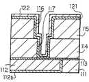
도 7a에 도시하는 바와 같이, 기판(예를 들면 반도체 기판)(91)(도시 생략) 상에 형성된 제 1 절연막(111)에 예를 들면 홈 배선 구조의 제 1 배선(112)이 배리어층(112b)을 통해 형성되어 있다. 상기 제 1 절연막(111) 상에는 제 1 배선(112)을 피복하는 확산 방지층(113)이 형성되며, 그 위에 제 2 절연막(114)이 형성되어 있다. 상기 확산 방지층(113)은 접속 구멍 형성 시의 에칭 스토퍼로서의 기능을 갖고 있어도 된다. 더욱이 제 2 절연막(114) 상에는 제 3 절연막(115)이 형성되어 있다. 제 3 절연막(115)에는 오목부(116)(이하 홈(116)으로 하여 설명한다)가 형성되며, 그 홈(116)의 바닥부로부터 제 2 절연막(114)을 관통하여 제 1 배선(112)에 이르는 접속 구멍(117)이 형성되어 있다.As shown in FIG. 7A, the
상기 구성의 배선 홈(116) 및 접속 구멍(117)의 내면에는 배리어층(121)이 형성되어 있다. 이 배리어층(121)은 예를 들면 질화 텅스텐으로 형성되어 있다. 더욱이 배리어층(121) 표면에는 예를 들면 스퍼터링 등의 성막 기술을 사용하여 구리 시드층(122)이 형성되어 있다. 이어서 전해 도금 챔버(61)에 의해, 고 어스팩트비의 홈 측벽, 접속 구멍 측벽에서의 구리 시드층의 막 두께 부족을 보충하기 위해 시드층 보강 전해 도금을 행한다. 그 때, 챔버 내를 비산화성 분위기로 하는 것이 바람직하다. 도면에서는 시드층 보강 전계 도금을 행한 구리 시드층(122)을 도시하였다. 그 후, 전해 도금 챔버(61) 내에서 기판을 세정한다. 이 세정은 예를 들면 수세에 의해 행한다. 혹은 반송장치(예를 들면 반송 로봇)(83)를 사용하여, 기판(91)을 액 처리 챔버(71)에 반송하고, 이 액 처리 챔버(71)에서 수세를 행 한다. 이후, 기판(91)의 반송은 상기 반송장치(83)에 의해 행한다.The
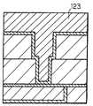
다음에, 도 7b에 도시하는 바와 같이, 반송장치(83)에 의해 전해 도금 챔버(11)의 홀더(12) 상에 기판(91)(도시 생략)을 반송한다. 그 때, 챔버 내를 비산화성 분위기로 하는 것이 바람직하다. 이 전해 도금 챔버(11)에서 구리 전해 도금을 행함으로써, 홈(116) 및 접속 구멍(117)을 구리로 이루어지는 도전층(123)에서 매입한다. 그 때, 제 3 절연막(115) 상의 배리어층(121) 상에도 구리로 이루어지는 도전층(123)이 퇴적된다. 또한, 도면에서는 구리 시드층(122)도 도전층(123)에 포함하여 그리고 있다. 이 전해 도금 공정의 시퀀스에서는 도금 후의 도전층(123) 표면이 평탄화되도록 도금 조건을 선택하여, 표면이 평탄한 구리 도금층을 형성한다. 그 후, 전해 도금 챔버(11) 내에서 기판(91)을 세정한다. 이 세정은 예를 들면 수세에 의해 행한다.Next, as shown to FIG. 7B, the board | substrate 91 (not shown) is conveyed on the
다음으로, 도 7c에 도시하는 바와 같이, 반송장치(83)에 의해 어닐링 챔버(41)의 홀더(42) 상에 기판(91)을 반송한다. 그 때, 챔버 내를 비산화성 분위기로 하는 것이 바람직하다. 이 어닐링 챔버(41)에서 상기 처리를 행한 기판(91)을 어닐링한다. 이 어닐링에 의해, 전해 도금 후의 미세한 결정립을 갖는 도전층(123)의 구리 결정립의 성장을 재촉한다.Next, as shown to FIG. 7C, the board |
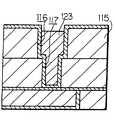
다음에, 도 7d에 도시하는 바와 같이, 반송장치(83)에 의해 전해 연마 챔버(21)의 홀더(22) 상에 기판(91)을 반송한다. 그 때, 챔버 내를 비산화성 분위기로 하는 것이 바람직하다. 이 전해 연마 챔버(21)에서 전해 연마를 실시하여 절연막(제 3 절연막(115)) 표면의 도전층(123)을 제거하여, 홈(116) 및 접속 구멍(117)의 내부에만 도전층(123)을 남긴다.Next, as shown in FIG. 7D, the
계속해서, 전해 연마 챔버(21) 내에서, 도 7e에 도시하는 바와 같이, 질화 텅스텐으로 이루어지는 배리어층(121)을 과산화수소수에 의한 웨트 에칭에 의해 제거한다. 즉, 기판 표면에 과산화수소수 용액을 스프레이하여, 평탄면 상의 불필요한 질화 텅스텐으로 이루어지는 배리어층(121)을 용해하여 제거한다. 질화 텅스텐의 에칭은 등방적으로 진행하기 때문에, 제 3 절연막(115) 표면의 질화 텅스텐을 완전히 제거하기 위해서는 어느 정도의 오버 에칭이 필요해진다. 그 결과, 홈(116)의 측벽에 사이드 에칭이 생겨, 배리어층(121)의 상단(121t)이 도전층(123)의 표면(123s)보다도 낮게 형성된다. 그 후, 전해 연마 챔버(21) 내에서 기판(91)을 세정한다. 이 세정은 예를 들면 수세에 의해 행한다.Subsequently, in the
다음으로, 도 7f에 도시하는 바와 같이, 반송장치(83)에 의해 무전해 도금 챔버(31)의 홀더(32) 상에 기판(91)을 반송한다. 그 때, 챔버 내를 비산화성 분위기로 하는 것이 바람직하다. 이 무전해 도금 챔버(31)에서 상기 처리를 행한 기판(91)을 무전해 도금에 의해, 노출하고 있는 도전층(123) 표면에 코발트 텅스텐 인(CoWP) 피막(124)을 선택적으로 형성한다. 이 성막의 선택성은 CoWP 무전해 도금을 실시하기 전에, 구리와의 치환 무전해 도금에 의해, 도전층(123) 표면을 팔라듐에 의해 피복해 둔다. 이 팔라듐 피복에 의해, CoWP의 성막은 팔라듐을 촉매로 하여 팔라듐 상에만 발생하는 것에 기인하고 있다. 일단, 팔라듐의 표면이 CoWP에 의해 피복된 후는 CoWP 자체를 촉매로 한 자기 촉매 도금에 의해, 선택성을 유지한 채로 CoWP의 도금 성장이 진행한다. 상기 질화 텅스텐으로 이루어지는 배리어층(121)의 에칭에서 발생한 사이드 에칭에 의한 도전층(123) 표면의 노출은 이 코발트 텅스텐 인 피막(124)에 의해 피복된다. 그 후, 무전해 도금 챔버(31) 내에서 기판(91)을 세정한다. 이 세정은 예를 들면 수세에 의해 행한다.Next, as shown to FIG. 7F, the board |
상기 실시예에서 설명한 비산화성 분위기는 각 비산화성 가스 공급부로부터 아르곤 등의 희귀 가스 혹은 질소를 챔버 내에 도입함과 동시에 배기부로부터 일부의 비산화성 가스를 배기하여, 챔버 내를 소정 압력의 비산화성 가스 분위기로 함으로써 형성된다.The non-oxidizing atmosphere described in the above embodiment introduces a rare gas such as argon or nitrogen into each chamber from each of the non-oxidizing gas supply sections, and exhausts a portion of the non-oxidizing gases from the exhaust section, thereby providing a non-oxidizing gas at a predetermined pressure in the chamber. It is formed by setting it as an atmosphere.
상기 실시예에서 설명한 재료 중, 배리어층(121)은 질화 텅스텐에 한정되는 것이 아니라, 동일한 기능을 갖는 재료, 예를 들면, 질화 텅스텐 등과 치환하는 것도 가능하다. 또한 상기 설명에서는 홈(116)에 매입된 구리로 이루어지는 도전층(123)에 코발트 텅스텐 인 피막(124)을 형성하는 기술을 설명하였지만, 예를 들면 접속 구멍 내에 구리 혹은 구리 합금으로 이루어지는 플러그를 형성하여, 그 플러그의 표면 측을 코발트 텅스텐 인 피막으로 피복하는 기술에도 적용할 수 있다.Of the materials described in the above embodiments, the
상기 제조 방법에 있어서, 기판 세정 후는 홀더를 고속 회전시킴으로써, 기판을 스핀 건조시켜도 된다.In the said manufacturing method, after cleaning a board | substrate, you may spin-dry a board | substrate by rotating a holder at high speed.
상기 제 2 반도체 장치의 제조 방법에서는 기판(91)을 산화성 분위기에 노출시키지 않고, 전해 도금, 전해 연마, 무전해 도금을 연속하여 행할 수 있으며, 또한 어닐링도 전해 도금, 전해 연마 혹은 무전해 도금에 연속하여 행하는 것이 가능해지기 때문에, 종래와 같이 각 처리를 단독으로 행하는 장치 사이를 둘러싸고 처리를 행하였던 제조 방법과 비교하여, TAT의 대폭적인 단축화를 도모할 수 있다.In the method of manufacturing the second semiconductor device, electrolytic plating, electropolishing and electroless plating can be performed continuously without exposing the
또한, 상기 반도체 장치의 제조 방법에서는 오목부(홈)(116) 내에 남기는 배리어층(121) 상단부가 도전층(123) 측면과 홈(116) 측벽과의 사이로 되도록 제 3 절연막(115) 표면의 배리어층(121)을 제거하고, 그 후 도전층(123) 측부에서 배리어층(121)에 접속함과 동시에 홈(116)의 개구 측에 있어서의 도전층(123)을 선택적으로 피복하는 코발트 텅스텐 인 피막(124)을 형성하기 때문에, 코발트 텅스텐 인 피막(124)은 도전층(123) 측부에서 배리어층(121)에 접속함과 동시에 홈(116)의 개구 측에 있어서의 도전층(123)을 선택적으로 피복하도록 형성된다. 또한, 코발트 텅스텐 인 피막(124)은 구리와의 계면에서 구리의 우선적 확산 경로로 되기 어렵기 때문에, 도전층(123)으로 구성되는 배선은 높은 일렉트로마이그레이션 내성(신뢰성)이 얻어진다.In the method of manufacturing the semiconductor device, the upper surface of the third
또한, 과산화수소수를 사용한 웨트 에칭에 의해, 제 3 절연막(115) 상의 배리어층(121)을 제거하고 있다. 그 때, 제 3 절연막(115) 표면의 배리어층(121)을 완전히 제거하기 위해, 오버 에칭을 행하는 것이 통례이다. 그 결과, 홈(116) 내에 잔류하는 배리어층(121) 상단부는 도전층(123) 측면과 홈(116) 측벽과의 사이로 된다. 그리고 홈(116) 측벽에 형성되어 있는 배리어층(121)은 그 상단이 도전층(123) 표면보다도 홈(116)의 바닥부 측으로 되도록 제거된다. 그로써, 코발트 텅스텐 인 피막(124)을 형성한 경우에, 도전층(123) 측부에서 배리어층(121)에 접속하도록 형성된다.The
이와 같이, 코발트 텅스텐 인 피막(124)이 도전층(123) 측부에서 배리어층(121)과 접속하기 때문에, 도전층(123)은 배리어층(121)과 코발트 텅스텐 인 피막(124)에 의하여 포함된 상태로 된다. 게다가, 그 접속 부분이 도전층(123)의 측부에 위치함으로써, 코발트 텅스텐 인 피막(124)은 도전층(123) 상면 및 측면의 상부 측에서 도전층(123)에 밀착하게 되어, 코발트 텅스텐 인 피막(124)은 벗겨지기 어려워진다. 그 결과, 코발트 텅스텐 인 피막(124)과 배리어층(121)과의 접속력도 강고해지기 때문에, 코발트 텅스텐 인 피막(124)과 배리어층(121)에 의하여, 도전층(123)의 구리 확산이 방지된다. 또한, 도전층(123)으로의 산소 확산도 방지되기 때문에 도전층 산화가 방지된다.As described above, since the cobalt
또한, 코발트 텅스텐 인 피막(124)을 사용함으로써, 표면이 화학적으로 불안정한 구리라도, 구리와 코발트 텅스텐 인과의 계면이 구리의 확산 경로로 되지 않기 때문에, 높은 일렉트로마이그레이션(electromigration) 내성(신뢰성)이 얻어진다.In addition, by using the cobalt
또한 산화하기 쉬운 구리 표면을 코발트 텅스텐 인 피막(124)으로 피복하기 때문에, 배선 시스템 전체의 기생 용량을 증대시키는 일이 없다.Moreover, since the copper surface which is easy to oxidize is coat | covered with the cobalt
또한, 코발트 텅스텐 인 피막(124)이 산화 방지막으로서 기능하기 때문에, 질화 실리콘막을 성막할 필요 없이, 직접 저유전율 절연막을 성막할 수 있기 때문에, 배선 시스템 전체의 배선 기생 저항을 대폭 저감할 수 있다.In addition, since the cobalt
이상, 설명한 바와 같이 본 발명의 제 1 반도체 제조 장치에 의하면, 전해 도금 챔버와 전해 연마 챔버를 구비하며, 상기 각 챔버가 반송장치를 구비한 반송 챔버에 접속되어 있기 때문에, 하나의 제조 장치에서 연속하여, 전해 도금과 전해 연마를 행할 수 있다. 게다가, 기판을 대기에 개방하지 않고, 기판 반송은 반송 챔버를 개재하는 것만으로 연속적으로 행할 수 있기 때문에, TAT의 대폭적인 단축화를 도모할 수 있다. 또한, 제거 공정을 CMP가 아니라 전해 연마로 행하도록 되어 있기 때문에, CMP와 같은 소모재에 높은 비용이 들지 않는다.As described above, according to the first semiconductor manufacturing apparatus of the present invention, the electroplating chamber and the electropolishing chamber are provided, and since the respective chambers are connected to the conveying chamber having the conveying apparatus, they are continuous in one manufacturing apparatus. Thus, electroplating and electropolishing can be performed. In addition, since the substrate can be conveyed continuously only through the transfer chamber without opening the substrate to the atmosphere, the TAT can be significantly shortened. In addition, since the removal process is performed by electropolishing instead of CMP, no high cost is required for consumables such as CMP.
본 발명의 제 2 반도체 제조 장치에 의하면, 전해 도금 챔버와 전해 연마 챔버와 무전해 도금 챔버와 어닐링 챔버를 구비하며, 상기 각 챔버가 반송장치를 구비한 반송 챔버에 접속되어 있기 때문에, 하나의 제조 장치에서 연속하여, 전해 도금과 전해 연마와 무전해 도금과 어닐링을 행할 수 있다. 게다가, 기판을 대기에 개방하지 않고, 기판의 반송은 반송 챔버를 개재하는 것만으로 각 챔버에 대하여 연속적으로 행할 수 있기 때문에, TAT의 대폭적인 단축화를 도모할 수 있다. 또한, 제거 공정을 CMP가 아니라 전해 연마로 행하도록 되어 있기 때문에, CMP와 같은 소모재에 높은 비용이 들지 않는다.According to the second semiconductor manufacturing apparatus of the present invention, an electroplating chamber, an electropolishing chamber, an electroless plating chamber, and an annealing chamber are provided, and each of the chambers is connected to a conveying chamber having a conveying apparatus. In the apparatus, electrolytic plating, electropolishing, electroless plating and annealing can be performed continuously. In addition, since the substrate can be conveyed continuously without opening the substrate to the atmosphere, only through the transfer chamber, the TAT can be significantly shortened. In addition, since the removal process is performed by electropolishing instead of CMP, no high cost is required for consumables such as CMP.
본 발명의 제 1 반도체 장치의 제조 방법에 의하면, 전해 도금과 전해 연마를 연속적으로 행하기 때문에, 종래와 같이 각 처리를 단독으로 행하는 장치 사이를 둘러싸고 처리를 행하였던 제조 방법과 비교하여, TAT의 대폭적인 단축화를 도모할 수 있다.According to the manufacturing method of the first semiconductor device of the present invention, since electroplating and electropolishing are carried out continuously, compared with the manufacturing method in which the treatment is carried out between devices that perform each treatment alone as in the prior art, Significantly shortening can be achieved.
본 발명의 제 2 반도체 장치의 제조 방법에 의하면, 기판을 산화성 분위기에 노출시키지 않고, 전해 도금, 전해 연마, 무전해 도금을 연속하여 행할 수 있으며, 또한 어닐링도 전해 도금, 전해 연마 혹은 무전해 도금에 연속하여 행하는 것이 가 능해지기 때문에, 종래와 같이 각 처리를 단독으로 행하는 장치 사이를 둘러싸고 처리를 행하였던 제조 방법과 비교하여, TAT의 대폭적인 단축화를 도모할 수 있다.According to the manufacturing method of the second semiconductor device of the present invention, electrolytic plating, electropolishing and electroless plating can be performed continuously without exposing the substrate to an oxidizing atmosphere, and annealing may also be performed by electroplating, electropolishing or electroless plating. Since it is possible to perform the process continuously, it is possible to significantly shorten the TAT, as compared with the manufacturing method in which the process is carried out by enclosing the apparatus which performs each process alone as in the prior art.
Claims (18)
Translated fromKoreanApplications Claiming Priority (2)
| Application Number | Priority Date | Filing Date | Title |
|---|---|---|---|
| JPJP-P-2000-00312834 | 2000-10-13 | ||
| JP2000312834AJP4644926B2 (en) | 2000-10-13 | 2000-10-13 | Semiconductor manufacturing apparatus and semiconductor device manufacturing method |
Publications (2)
| Publication Number | Publication Date |
|---|---|
| KR20020065562A KR20020065562A (en) | 2002-08-13 |
| KR100822651B1true KR100822651B1 (en) | 2008-04-17 |
Family
ID=18792344
Family Applications (1)
| Application Number | Title | Priority Date | Filing Date |
|---|---|---|---|
| KR1020027007480AExpired - Fee RelatedKR100822651B1 (en) | 2000-10-13 | 2001-10-12 | Semiconductor manufacturing device and manufacturing method of semiconductor device |
Country Status (5)
| Country | Link |
|---|---|
| US (2) | US6809029B2 (en) |
| JP (1) | JP4644926B2 (en) |
| KR (1) | KR100822651B1 (en) |
| TW (1) | TW567580B (en) |
| WO (1) | WO2002031231A1 (en) |
Cited By (1)
| Publication number | Priority date | Publication date | Assignee | Title |
|---|---|---|---|---|
| KR20210130466A (en) | 2020-04-22 | 2021-11-01 | 한양대학교 에리카산학협력단 | Continuous Electrolytic Apparatus And Method |
Families Citing this family (65)
| Publication number | Priority date | Publication date | Assignee | Title |
|---|---|---|---|---|
| US7153195B2 (en)* | 2000-08-30 | 2006-12-26 | Micron Technology, Inc. | Methods and apparatus for selectively removing conductive material from a microelectronic substrate |
| US7220166B2 (en)* | 2000-08-30 | 2007-05-22 | Micron Technology, Inc. | Methods and apparatus for electromechanically and/or electrochemically-mechanically removing conductive material from a microelectronic substrate |
| US7112121B2 (en)* | 2000-08-30 | 2006-09-26 | Micron Technology, Inc. | Methods and apparatus for electrical, mechanical and/or chemical removal of conductive material from a microelectronic substrate |
| US7078308B2 (en)* | 2002-08-29 | 2006-07-18 | Micron Technology, Inc. | Method and apparatus for removing adjacent conductive and nonconductive materials of a microelectronic substrate |
| US7192335B2 (en)* | 2002-08-29 | 2007-03-20 | Micron Technology, Inc. | Method and apparatus for chemically, mechanically, and/or electrolytically removing material from microelectronic substrates |
| US7129160B2 (en)* | 2002-08-29 | 2006-10-31 | Micron Technology, Inc. | Method for simultaneously removing multiple conductive materials from microelectronic substrates |
| US7134934B2 (en)* | 2000-08-30 | 2006-11-14 | Micron Technology, Inc. | Methods and apparatus for electrically detecting characteristics of a microelectronic substrate and/or polishing medium |
| FR2815046B1 (en) | 2000-10-11 | 2003-01-10 | Vetrotex France Sa | METHOD AND DEVICE FOR PRODUCING A COMPOSITE YARN |
| US6896776B2 (en)* | 2000-12-18 | 2005-05-24 | Applied Materials Inc. | Method and apparatus for electro-chemical processing |
| US20060169597A1 (en)* | 2001-03-14 | 2006-08-03 | Applied Materials, Inc. | Method and composition for polishing a substrate |
| US7323416B2 (en)* | 2001-03-14 | 2008-01-29 | Applied Materials, Inc. | Method and composition for polishing a substrate |
| US7582564B2 (en)* | 2001-03-14 | 2009-09-01 | Applied Materials, Inc. | Process and composition for conductive material removal by electrochemical mechanical polishing |
| US6899804B2 (en)* | 2001-04-10 | 2005-05-31 | Applied Materials, Inc. | Electrolyte composition and treatment for electrolytic chemical mechanical polishing |
| US7232514B2 (en)* | 2001-03-14 | 2007-06-19 | Applied Materials, Inc. | Method and composition for polishing a substrate |
| US7128825B2 (en) | 2001-03-14 | 2006-10-31 | Applied Materials, Inc. | Method and composition for polishing a substrate |
| US6811680B2 (en)* | 2001-03-14 | 2004-11-02 | Applied Materials Inc. | Planarization of substrates using electrochemical mechanical polishing |
| US7160432B2 (en)* | 2001-03-14 | 2007-01-09 | Applied Materials, Inc. | Method and composition for polishing a substrate |
| JP2005229121A (en)* | 2001-03-16 | 2005-08-25 | Ebara Corp | Device and method of forming wiring |
| US20070295611A1 (en)* | 2001-12-21 | 2007-12-27 | Liu Feng Q | Method and composition for polishing a substrate |
| JP4042408B2 (en)* | 2002-01-07 | 2008-02-06 | ソニー株式会社 | Method for producing copper film |
| TWI275436B (en)* | 2002-01-31 | 2007-03-11 | Ebara Corp | Electrochemical machining device, and substrate processing apparatus and method |
| JP2003332274A (en)* | 2002-05-17 | 2003-11-21 | Tokyo Seimitsu Co Ltd | Chemical mechanical polishing method and chemical mechanical polishing apparatus |
| EP1540044A2 (en) | 2002-06-28 | 2005-06-15 | Advanced Micro Devices, Inc. | Apparatus and method for treating a substrate electrochemically while reducing metal corrosion |
| JP3636186B2 (en)* | 2002-10-11 | 2005-04-06 | ソニー株式会社 | Manufacturing method of semiconductor device |
| US7390429B2 (en)* | 2003-06-06 | 2008-06-24 | Applied Materials, Inc. | Method and composition for electrochemical mechanical polishing processing |
| JP2005015885A (en)* | 2003-06-27 | 2005-01-20 | Ebara Corp | Substrate processing method and apparatus |
| US20050048768A1 (en)* | 2003-08-26 | 2005-03-03 | Hiroaki Inoue | Apparatus and method for forming interconnects |
| US7112122B2 (en)* | 2003-09-17 | 2006-09-26 | Micron Technology, Inc. | Methods and apparatus for removing conductive material from a microelectronic substrate |
| US20050092620A1 (en)* | 2003-10-01 | 2005-05-05 | Applied Materials, Inc. | Methods and apparatus for polishing a substrate |
| WO2005045906A1 (en)* | 2003-10-29 | 2005-05-19 | Asm Nutool, Inc. | System and method for electroless surface conditioning |
| US7390744B2 (en) | 2004-01-29 | 2008-06-24 | Applied Materials, Inc. | Method and composition for polishing a substrate |
| US7153777B2 (en) | 2004-02-20 | 2006-12-26 | Micron Technology, Inc. | Methods and apparatuses for electrochemical-mechanical polishing |
| JP3910973B2 (en)* | 2004-04-22 | 2007-04-25 | 株式会社東芝 | Manufacturing method of semiconductor device |
| US7566391B2 (en) | 2004-09-01 | 2009-07-28 | Micron Technology, Inc. | Methods and systems for removing materials from microfeature workpieces with organic and/or non-aqueous electrolytic media |
| US7084064B2 (en) | 2004-09-14 | 2006-08-01 | Applied Materials, Inc. | Full sequence metal and barrier layer electrochemical mechanical processing |
| JP2006120870A (en)* | 2004-10-21 | 2006-05-11 | Ebara Corp | Wire formation method and device thereof |
| US20060197183A1 (en)* | 2005-03-01 | 2006-09-07 | International Business Machines Corporation | Improved mim capacitor structure and process |
| US7317253B2 (en)* | 2005-04-25 | 2008-01-08 | Sony Corporation | Cobalt tungsten phosphate used to fill voids arising in a copper metallization process |
| US20060249394A1 (en)* | 2005-05-05 | 2006-11-09 | Applied Materials, Inc. | Process and composition for electrochemical mechanical polishing |
| US20060249395A1 (en)* | 2005-05-05 | 2006-11-09 | Applied Material, Inc. | Process and composition for electrochemical mechanical polishing |
| FR2899243B1 (en) | 2006-03-30 | 2008-05-16 | Saint Gobain Vetrotex | METHOD AND DEVICE FOR MANUFACTURING A COMPOSITE WIRE |
| FR2899571B1 (en) | 2006-04-10 | 2009-02-06 | Saint Gobain Vetrotex | METHOD FOR MANUFACTURING A SEPARATE WIRE WINDING |
| US20070254485A1 (en)* | 2006-04-28 | 2007-11-01 | Daxin Mao | Abrasive composition for electrochemical mechanical polishing |
| DE102006040585B4 (en)* | 2006-08-30 | 2013-02-07 | Infineon Technologies Ag | A method of filling a trench in a semiconductor product |
| US7964496B2 (en) | 2006-11-21 | 2011-06-21 | Taiwan Semiconductor Manufacturing Company, Ltd. | Schemes for forming barrier layers for copper in interconnect structures |
| US20090127711A1 (en)* | 2007-11-15 | 2009-05-21 | International Business Machines Corporation | Interconnect structure and method of making same |
| JP4950981B2 (en)* | 2008-11-10 | 2012-06-13 | 株式会社東京精密 | Chemical mechanical polishing apparatus and chemical mechanical polishing method |
| CN102220571B (en)* | 2010-04-15 | 2014-10-15 | 鸿富锦精密工业(深圳)有限公司 | Wet-type coating system |
| US8912658B2 (en) | 2010-10-29 | 2014-12-16 | International Business Machines Corporation | Interconnect structure with enhanced reliability |
| JP2012151289A (en)* | 2011-01-19 | 2012-08-09 | Furukawa Electric Co Ltd:The | Optical semiconductor mounting board, manufacturing method of the same and optical semiconductor device |
| CN102800621B (en)* | 2011-05-25 | 2014-07-30 | 中芯国际集成电路制造(上海)有限公司 | Method for forming embolism structure and semiconductor device |
| CN102446829A (en)* | 2011-09-23 | 2012-05-09 | 上海华力微电子有限公司 | Device for electroplating copper in through hole of silicon wafer |
| US8956974B2 (en)* | 2012-06-29 | 2015-02-17 | Micron Technology, Inc. | Devices, systems, and methods related to planarizing semiconductor devices after forming openings |
| JP6328977B2 (en)* | 2014-03-31 | 2018-05-23 | 株式会社荏原製作所 | Substrate polishing equipment |
| CN105097651B (en)* | 2014-05-07 | 2019-12-24 | 盛美半导体设备(上海)有限公司 | Copper plating and thinning integrated device |
| US12276027B2 (en)* | 2019-03-28 | 2025-04-15 | Tokyo Electron Limited | Substrate processing apparatus and substrate processing method |
| US10998209B2 (en) | 2019-05-31 | 2021-05-04 | Applied Materials, Inc. | Substrate processing platforms including multiple processing chambers |
| US12080571B2 (en) | 2020-07-08 | 2024-09-03 | Applied Materials, Inc. | Substrate processing module and method of moving a workpiece |
| US11749542B2 (en) | 2020-07-27 | 2023-09-05 | Applied Materials, Inc. | Apparatus, system, and method for non-contact temperature monitoring of substrate supports |
| US11817331B2 (en) | 2020-07-27 | 2023-11-14 | Applied Materials, Inc. | Substrate holder replacement with protective disk during pasting process |
| US11600507B2 (en) | 2020-09-09 | 2023-03-07 | Applied Materials, Inc. | Pedestal assembly for a substrate processing chamber |
| US11610799B2 (en) | 2020-09-18 | 2023-03-21 | Applied Materials, Inc. | Electrostatic chuck having a heating and chucking capabilities |
| US12195314B2 (en) | 2021-02-02 | 2025-01-14 | Applied Materials, Inc. | Cathode exchange mechanism to improve preventative maintenance time for cluster system |
| US11674227B2 (en) | 2021-02-03 | 2023-06-13 | Applied Materials, Inc. | Symmetric pump down mini-volume with laminar flow cavity gas injection for high and low pressure |
| US12002668B2 (en) | 2021-06-25 | 2024-06-04 | Applied Materials, Inc. | Thermal management hardware for uniform temperature control for enhanced bake-out for cluster tool |
Citations (1)
| Publication number | Priority date | Publication date | Assignee | Title |
|---|---|---|---|---|
| JPH02217498A (en)* | 1989-02-17 | 1990-08-30 | Shinmei Kogyo Kk | Plating treatment system |
Family Cites Families (16)
| Publication number | Priority date | Publication date | Assignee | Title |
|---|---|---|---|---|
| JPS511326A (en)* | 1974-06-25 | 1976-01-08 | Sumitomo Electric Industries | METSUKI MAESHORIHOHO |
| JPS57143838A (en)* | 1981-02-27 | 1982-09-06 | Mitsubishi Electric Corp | Manufacture of semiconductor device |
| JPS60138090A (en)* | 1983-12-26 | 1985-07-22 | Toppan Printing Co Ltd | Partial silver plating method |
| JPH09256200A (en)* | 1996-03-19 | 1997-09-30 | Hitachi Cable Ltd | Plating film surface treatment method |
| US6017437A (en)* | 1997-08-22 | 2000-01-25 | Cutek Research, Inc. | Process chamber and method for depositing and/or removing material on a substrate |
| TW405158B (en)* | 1997-09-17 | 2000-09-11 | Ebara Corp | Plating apparatus for semiconductor wafer processing |
| US6197123B1 (en)* | 1997-12-18 | 2001-03-06 | Texas Instruments Incorporated | Method for cleaning a process chamber used for manufacturing substrates during nonproduction intervals |
| JP2000100893A (en)* | 1998-09-18 | 2000-04-07 | Dainippon Screen Mfg Co Ltd | Wafer treatment device |
| WO2000033356A2 (en)* | 1998-11-28 | 2000-06-08 | Acm Research, Inc | Methods and apparatus for holding and positioning semiconductor workpieces during electropolishing and/or electroplating of the workpieces |
| US6328872B1 (en)* | 1999-04-03 | 2001-12-11 | Nutool, Inc. | Method and apparatus for plating and polishing a semiconductor substrate |
| US6136163A (en)* | 1999-03-05 | 2000-10-24 | Applied Materials, Inc. | Apparatus for electro-chemical deposition with thermal anneal chamber |
| US6440261B1 (en)* | 1999-05-25 | 2002-08-27 | Applied Materials, Inc. | Dual buffer chamber cluster tool for semiconductor wafer processing |
| US6503375B1 (en)* | 2000-02-11 | 2003-01-07 | Applied Materials, Inc | Electroplating apparatus using a perforated phosphorus doped consumable anode |
| JP4055334B2 (en)* | 2000-06-13 | 2008-03-05 | ソニー株式会社 | Manufacturing method of semiconductor device |
| US6747734B1 (en)* | 2000-07-08 | 2004-06-08 | Semitool, Inc. | Apparatus and method for processing a microelectronic workpiece using metrology |
| KR100434946B1 (en)* | 2001-09-28 | 2004-06-10 | 학교법인 성균관대학 | Method for forming Cu interconnection of semiconductor device using electroless plating |
- 2000
- 2000-10-13JPJP2000312834Apatent/JP4644926B2/ennot_activeExpired - Fee Related
- 2001
- 2001-10-08TWTW090124825Apatent/TW567580B/ennot_activeIP Right Cessation
- 2001-10-12KRKR1020027007480Apatent/KR100822651B1/ennot_activeExpired - Fee Related
- 2001-10-12WOPCT/JP2001/008981patent/WO2002031231A1/enactiveApplication Filing
- 2001-10-12USUS10/149,858patent/US6809029B2/ennot_activeExpired - Fee Related
- 2004
- 2004-02-10USUS10/775,935patent/US20040159553A1/ennot_activeAbandoned
Patent Citations (1)
| Publication number | Priority date | Publication date | Assignee | Title |
|---|---|---|---|---|
| JPH02217498A (en)* | 1989-02-17 | 1990-08-30 | Shinmei Kogyo Kk | Plating treatment system |
Cited By (1)
| Publication number | Priority date | Publication date | Assignee | Title |
|---|---|---|---|---|
| KR20210130466A (en) | 2020-04-22 | 2021-11-01 | 한양대학교 에리카산학협력단 | Continuous Electrolytic Apparatus And Method |
Also Published As
| Publication number | Publication date |
|---|---|
| JP2002121698A (en) | 2002-04-26 |
| KR20020065562A (en) | 2002-08-13 |
| US20030113996A1 (en) | 2003-06-19 |
| WO2002031231A1 (en) | 2002-04-18 |
| TW567580B (en) | 2003-12-21 |
| US6809029B2 (en) | 2004-10-26 |
| JP4644926B2 (en) | 2011-03-09 |
| US20040159553A1 (en) | 2004-08-19 |
Similar Documents
| Publication | Publication Date | Title |
|---|---|---|
| KR100822651B1 (en) | Semiconductor manufacturing device and manufacturing method of semiconductor device | |
| US7172497B2 (en) | Fabrication of semiconductor interconnect structures | |
| US6117781A (en) | Optimized trench/via profile for damascene processing | |
| US7070687B2 (en) | Apparatus and method of surface treatment for electrolytic and electroless plating of metals in integrated circuit manufacturing | |
| US6410418B1 (en) | Recess metallization via selective insulator formation on nucleation/seed layer | |
| KR100446300B1 (en) | Method for forming metal interconnections of semiconductor device | |
| TWI393186B (en) | Processes and integrated systems for engineering a substrate surface for metal deposition | |
| US20090017621A1 (en) | Manufacturing method for semiconductor device and manufacturing device of semiconductor device | |
| US20050282378A1 (en) | Interconnects forming method and interconnects forming apparatus | |
| WO2001078123A1 (en) | Method of forming metal interconnects | |
| US6518173B1 (en) | Method for avoiding fluorine contamination of copper interconnects | |
| US20060003570A1 (en) | Method and apparatus for electroless capping with vapor drying | |
| US6689689B1 (en) | Selective deposition process for allowing damascene-type Cu interconnect lines | |
| US20050048768A1 (en) | Apparatus and method for forming interconnects | |
| US20030040177A1 (en) | Method for forming metal interconnections using electroless plating | |
| JP2001181851A (en) | Plating method and plated structure | |
| KR20040008205A (en) | Electroless-plating solution and semiconductor device | |
| US20040248405A1 (en) | Method of and apparatus for manufacturing semiconductor device | |
| KR20040033260A (en) | Method of producing semiconductor device | |
| JP2006120870A (en) | Wire formation method and device thereof | |
| KR100351237B1 (en) | Apparatus for forming a copper wiring in a semiconducotr device and method of forming a copper wiring by utilaing the same | |
| CN112687610B (en) | Interconnect structure and method of forming the same | |
| US20060137994A1 (en) | Method of wafer processing with edge seed layer removal | |
| KR100456259B1 (en) | Method of forming a copper wiring in a semiconductor device | |
| KR100701675B1 (en) | Copper wiring formation method of semiconductor device |
Legal Events
| Date | Code | Title | Description |
|---|---|---|---|
| PA0105 | International application | St.27 status event code:A-0-1-A10-A15-nap-PA0105 | |
| PG1501 | Laying open of application | St.27 status event code:A-1-1-Q10-Q12-nap-PG1501 | |
| R17-X000 | Change to representative recorded | St.27 status event code:A-3-3-R10-R17-oth-X000 | |
| A201 | Request for examination | ||
| PA0201 | Request for examination | St.27 status event code:A-1-2-D10-D11-exm-PA0201 | |
| R17-X000 | Change to representative recorded | St.27 status event code:A-3-3-R10-R17-oth-X000 | |
| R17-X000 | Change to representative recorded | St.27 status event code:A-3-3-R10-R17-oth-X000 | |
| R18-X000 | Changes to party contact information recorded | St.27 status event code:A-3-3-R10-R18-oth-X000 | |
| E902 | Notification of reason for refusal | ||
| PE0902 | Notice of grounds for rejection | St.27 status event code:A-1-2-D10-D21-exm-PE0902 | |
| E13-X000 | Pre-grant limitation requested | St.27 status event code:A-2-3-E10-E13-lim-X000 | |
| P11-X000 | Amendment of application requested | St.27 status event code:A-2-2-P10-P11-nap-X000 | |
| P13-X000 | Application amended | St.27 status event code:A-2-2-P10-P13-nap-X000 | |
| R17-X000 | Change to representative recorded | St.27 status event code:A-3-3-R10-R17-oth-X000 | |
| E701 | Decision to grant or registration of patent right | ||
| PE0701 | Decision of registration | St.27 status event code:A-1-2-D10-D22-exm-PE0701 | |
| GRNT | Written decision to grant | ||
| PR0701 | Registration of establishment | St.27 status event code:A-2-4-F10-F11-exm-PR0701 | |
| PR1002 | Payment of registration fee | St.27 status event code:A-2-2-U10-U12-oth-PR1002 Fee payment year number:1 | |
| PG1601 | Publication of registration | St.27 status event code:A-4-4-Q10-Q13-nap-PG1601 | |
| PN2301 | Change of applicant | St.27 status event code:A-5-5-R10-R13-asn-PN2301 St.27 status event code:A-5-5-R10-R11-asn-PN2301 | |
| FPAY | Annual fee payment | Payment date:20110405 Year of fee payment:4 | |
| PR1001 | Payment of annual fee | St.27 status event code:A-4-4-U10-U11-oth-PR1001 Fee payment year number:4 | |
| LAPS | Lapse due to unpaid annual fee | ||
| PC1903 | Unpaid annual fee | St.27 status event code:A-4-4-U10-U13-oth-PC1903 Not in force date:20120411 Payment event data comment text:Termination Category : DEFAULT_OF_REGISTRATION_FEE | |
| PC1903 | Unpaid annual fee | St.27 status event code:N-4-6-H10-H13-oth-PC1903 Ip right cessation event data comment text:Termination Category : DEFAULT_OF_REGISTRATION_FEE Not in force date:20120411 | |
| P22-X000 | Classification modified | St.27 status event code:A-4-4-P10-P22-nap-X000 | |
| PN2301 | Change of applicant | St.27 status event code:A-5-5-R10-R13-asn-PN2301 St.27 status event code:A-5-5-R10-R11-asn-PN2301 |