KR100821108B1 - Biological sealant storage and dispensing device - Google Patents
Biological sealant storage and dispensing deviceDownload PDFInfo
- Publication number
- KR100821108B1 KR100821108B1KR1020020017720AKR20020017720AKR100821108B1KR 100821108 B1KR100821108 B1KR 100821108B1KR 1020020017720 AKR1020020017720 AKR 1020020017720AKR 20020017720 AKR20020017720 AKR 20020017720AKR 100821108 B1KR100821108 B1KR 100821108B1
- Authority
- KR
- South Korea
- Prior art keywords
- dispenser
- sealant
- cartridge
- recesses
- cartridges
- Prior art date
- Legal status (The legal status is an assumption and is not a legal conclusion. Google has not performed a legal analysis and makes no representation as to the accuracy of the status listed.)
- Expired - Fee Related
Links
Images


Classifications
- A—HUMAN NECESSITIES
- A61—MEDICAL OR VETERINARY SCIENCE; HYGIENE
- A61M—DEVICES FOR INTRODUCING MEDIA INTO, OR ONTO, THE BODY; DEVICES FOR TRANSDUCING BODY MEDIA OR FOR TAKING MEDIA FROM THE BODY; DEVICES FOR PRODUCING OR ENDING SLEEP OR STUPOR
- A61M5/00—Devices for bringing media into the body in a subcutaneous, intra-vascular or intramuscular way; Accessories therefor, e.g. filling or cleaning devices, arm-rests
- A61M5/178—Syringes
- A61M5/30—Syringes for injection by jet action, without needle, e.g. for use with replaceable ampoules or carpules
- A—HUMAN NECESSITIES
- A61—MEDICAL OR VETERINARY SCIENCE; HYGIENE
- A61B—DIAGNOSIS; SURGERY; IDENTIFICATION
- A61B17/00—Surgical instruments, devices or methods
- A61B17/00491—Surgical glue applicators
- A—HUMAN NECESSITIES
- A61—MEDICAL OR VETERINARY SCIENCE; HYGIENE
- A61P—SPECIFIC THERAPEUTIC ACTIVITY OF CHEMICAL COMPOUNDS OR MEDICINAL PREPARATIONS
- A61P7/00—Drugs for disorders of the blood or the extracellular fluid
- A61P7/04—Antihaemorrhagics; Procoagulants; Haemostatic agents; Antifibrinolytic agents
- A—HUMAN NECESSITIES
- A61—MEDICAL OR VETERINARY SCIENCE; HYGIENE
- A61B—DIAGNOSIS; SURGERY; IDENTIFICATION
- A61B17/00—Surgical instruments, devices or methods
- A61B17/00491—Surgical glue applicators
- A61B2017/00495—Surgical glue applicators for two-component glue
Landscapes
- Health & Medical Sciences (AREA)
- Life Sciences & Earth Sciences (AREA)
- Animal Behavior & Ethology (AREA)
- Surgery (AREA)
- Engineering & Computer Science (AREA)
- General Health & Medical Sciences (AREA)
- Public Health (AREA)
- Veterinary Medicine (AREA)
- Biomedical Technology (AREA)
- Heart & Thoracic Surgery (AREA)
- Nuclear Medicine, Radiotherapy & Molecular Imaging (AREA)
- Medical Informatics (AREA)
- Molecular Biology (AREA)
- Hematology (AREA)
- Diabetes (AREA)
- Pharmacology & Pharmacy (AREA)
- Chemical & Material Sciences (AREA)
- Chemical Kinetics & Catalysis (AREA)
- General Chemical & Material Sciences (AREA)
- Medicinal Chemistry (AREA)
- Organic Chemistry (AREA)
- Bioinformatics & Cheminformatics (AREA)
- Vascular Medicine (AREA)
- Anesthesiology (AREA)
- Coating Apparatus (AREA)
- Infusion, Injection, And Reservoir Apparatuses (AREA)
- Sampling And Sample Adjustment (AREA)
- Containers And Packaging Bodies Having A Special Means To Remove Contents (AREA)
Abstract
Translated fromKoreanDescription
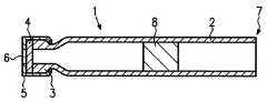
Translated fromKorean도 1은 액상 성분의 밀봉제용 저장 컨테이너의 종방향 단면도.1 is a longitudinal sectional view of a storage container for a sealant of a liquid component;
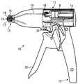
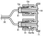
도 2는 밀봉제의 성분들을 동시에 분배하기 위한 분배기의 개략적인 단면도.2 is a schematic cross-sectional view of a dispenser for simultaneously dispensing the components of a sealant.
도 3은 분배기, 카트리지, 및 드라이버 부분이 장전을 위해 정렬되어 있는 것을 도시하는 사시도.3 is a perspective view showing the dispenser, cartridge, and driver portions aligned for loading.
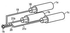
도 4는 도 2의 분배기의 내부 배관의 제 1 구성을 개략적으로 도시하는 사시도.4 is a perspective view schematically showing a first configuration of the internal piping of the distributor of FIG. 2;
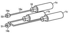
도 5는 도 2의 분배기의 내부 배관의 제 2 구성을 개략적으로 도시하는 사시도.FIG. 5 is a perspective view schematically showing a second configuration of the internal piping of the distributor of FIG. 2; FIG.
도 6은 분배기의 제 2 실시예의 개략적인 사시도.6 is a schematic perspective view of a second embodiment of a dispenser.
도 7은 도 6의 분배기의 내부 배관의 구성을 개략적으로 도시하는 사시도.FIG. 7 is a perspective view schematically showing a configuration of internal piping of the distributor of FIG. 6. FIG.
도 8은 도 6의 분배기와 이중 루멘 카테터 사이의 연결관계를 도시하는 개략적인 단면도.FIG. 8 is a schematic cross sectional view showing a connection between the distributor and the dual lumen catheter of FIG. 6; FIG.
도 9a, 도 9b 및 도 9c는 각각 분배기의 제 3 실시예의 단면도, 측단면도 및 평면도.9A, 9B and 9C are cross sectional, side sectional and plan views, respectively, of a third embodiment of a dispenser.
도 10a 및 도 10b는 각각 도 9의 분배기용 푸시로드의 단면도 및 측면도.10A and 10B are cross-sectional and side views, respectively, of the push rod for the dispenser of FIG. 9;
* 도면의 주요부분에 대한 부호의 설명 *Explanation of symbols on the main parts of the drawings
1 : 카트리지7 : 후방 단부1 cartridge 7 rear end
8 : 피스톤10 : 분배기8: piston 10: distributor
11 : 수용부12 : 고정 손잡이11: receptacle 12: fixed handle
13 : "루어(Luer)"형 연결부30 : 방아쇠13 "luer" type connection 30: trigger
본 발명은 생물학적 밀봉제와 같은 다중-성분 혼합물을 저장 및 분배하기 위한 방법 및 장치에 관한 것이다.The present invention relates to methods and apparatus for storing and dispensing multi-component mixtures such as biological sealants.
생물학적 밀봉제는 출혈(haemorrhage)을 방지 또는 감소시키거나, 봉합부(sutures)를 지지하거나, 또는 강(cavities)을 밀봉하는 수단으로서 외과 수술에서 폭넓게 사용되고 있다. 종래의 밀봉제는 두가지 성분을 혼합함으로써 준비된다. 피브린(fibrin) 밀봉제의 경우에, 상기 성분들은 피브리노겐(fibrinogen)과 트롬빈(thrombin)을 포함하고, 두가지 냉동-건조된 분말 형태로 또는 두가지 냉동된 액체 형태로 보관된다. 상기 분말은 사용하기 전에 수성 액체로 다시 수화시키고(rehydrating) 그 용액을 이중 주사기(dual syringe)에 장전함으로써 준비된다. 상기 냉동된 액체는 사용을 위해 액체 형태로 해동시키고 그 액체를 이중 주사기에 장전함으로써 준비된다. 상처부위 또는 절개부위에 두가지 성분을 동시에 분배함으로써, 상기 성분들은 적용 부위에서 함께 혼합되어, 절개된 혈관으로부터의 출혈을 감소 또는 방지하는 응괴(clotting)를 형성한다.Biological sealants are widely used in surgical operations as a means of preventing or reducing haemorrhage, supporting sutures, or sealing cavities. Conventional sealants are prepared by mixing the two components. In the case of fibrin sealants, the components include fibrinogen and thrombin and are stored in two freeze-dried powder forms or in two frozen liquid forms. The powder is prepared by rehydrating with an aqueous liquid prior to use and loading the solution into a dual syringe. The frozen liquid is prepared by thawing in liquid form for use and loading the liquid into a double syringe. By simultaneously dispensing the two components at the wound or incision site, the components are mixed together at the site of application to form clotting that reduces or prevents bleeding from the incised blood vessel.
종래의 2-성분 밀봉제의 분말 형태가 2 내지 8℃의 냉장 온도에서 연장된 저장 수명을 가지지만, 상기 성분들은 분말 형태로 저장되기 때문에, 분배 및 혼합을 위해서는 액체 형태로 변환되어야만 한다. 밀봉제는 사용을 위해 대략 30분 전에 준비되고, 상기 성분들은 사용하기 위해 다시 수화하여 주사기에 개별적으로 장전됨으로써 준비되어야만 한다. 냉동된 형태의 2-성분 밀봉제의 단점은 냉동 온도가 유지되어야만 한다는 것과 사용하기 전에 해동되어야만 한다는 것이다. 또한, 상기 성분들은 해동 후에는 제한된 안정성을 갖는다.Although the powder form of conventional two-component sealants has an extended shelf life at refrigeration temperatures of 2 to 8 ° C., since the ingredients are stored in powder form, they must be converted to liquid form for dispensing and mixing. The sealant is prepared approximately 30 minutes prior to use, and the components must be prepared by hydrating and loading the syringe separately for use. The disadvantages of the frozen form of the two-component sealant are that the freezing temperature must be maintained and must be thawed before use. In addition, the components have limited stability after thawing.
사용 전에 밀봉제를 준비하는데 필요한 상기 조건은, 수술 중에 밀봉제가 외부로 흐르게 되는 위험보다는, 두가지 단점 즉, 첫째로 밀봉제를 즉시 이용할 수 없다는 단점과, 둘째로 준비에 필요한 시간이 너무 길어서 작업 현장의 요원이 과도한 양의 밀봉제를 준비하게 될 수 있다는 단점을 초래한다. 이와 같이 과도한 양을 준비하게 되면 밀봉제를 낭비하게 된다.The above conditions necessary to prepare the sealant prior to use are, rather than the risk of the sealant flowing out during operation, two disadvantages: first, the sealant is not readily available, and secondly, the time required for preparation is too long. This results in the disadvantage that the agent may be prepared to prepare an excessive amount of sealant. Preparing an excessive amount in this way wastes the sealant.
밀봉제의 세가지 성분이 개별적으로 냉장 조건하에서 연장된 기간동안 액체 형태로 저장될 수 있는 선택적인 형태의 생물학적 밀봉제가 최근에 발견되었다. 상기 밀봉제는 PCT 공보 WO 00/29041호에 개시되어 있다. 상기 세가지 성분은 각각 피브리노겐, 트롬빈, 및 인자 XIII(factor XIII)를 포함한다. 이들 성분이 함께 혼합되면, 응괴를 형성한다. 트롬빈과 인자 XIII 성분은 초기에 함께 혼합될 수 있으며, 이러한 2-성분 혼합물이 나중에 피브리노겐과 함께 혼합될 수 있다는 것 또한 발견되었다. 밀봉제 성분들을 액체 형태로 저장하면, 상기 성분들을 수화 또는 해 동하여 준비할 필요 없이, 사용하기 위해 상기 성분들을 즉시 이용할 수 있다는 점에서 유리하다. 그러므로, 상기 밀봉제는 즉시 준비될 수 있으며 낭비량은 감소된다.Recently, selective forms of biological sealants have been found in which the three components of the seal can be stored in liquid form for extended periods of time under individually refrigerated conditions. Such sealants are disclosed in PCT publication WO 00/29041. These three components each include fibrinogen, thrombin, and factor XIII. When these components are mixed together, they form a clot. It has also been found that the thrombin and Factor XIII components can be initially mixed together and this two-component mixture can later be mixed with fibrinogen. The storage of the sealant components in a liquid form is advantageous in that the components can be used immediately for use without the need to prepare them by hydration or thawing. Therefore, the sealant can be prepared immediately and the waste amount is reduced.
본 발명은 3-성분 밀봉제와 같은 다중-성분 혼합물과 함께 사용하기 위한 분배 방법 및 장치와 저장 컨테이너를 제공하고, 상기 성분들은 액체 형태이거나 또는 현재 시판 중인 제품에 비해 증대된 저장 안정성을 나타내는 액체 상태로 직접 변환될 수 있는 냉동 상태이다. 또한, 다중-성분 밀봉제의 성분들을 혼합하는 순서가 제공된다.The present invention provides a dispensing method and apparatus and a storage container for use with a multi-component mixture, such as a three-component sealant, wherein the components are in liquid form or are liquids exhibiting increased storage stability over current commercially available products. A frozen state that can be converted directly to a state. Also provided is an order of mixing the components of the multi-component sealant.
본 발명의 저장 컨테이너(카트리지)의 양호한 형태에 있어서, 상기 컨테이너는 개방될 수 있는 밀봉체에 의해 일단부가 폐쇄되고 관형 몸체에 대해 축방향으로 이동할 수 있는 피스톤 소자에 의해 타단부가 밀봉되는 관형 몸체를 포함한다.In a preferred form of the storage container (cartridge) of the present invention, the container has a tubular body whose one end is closed by an openable seal and the other end is sealed by a piston element that is axially movable relative to the tubular body. It includes.
분배기의 양호한 형태에 있어서, 분배기는 분배될 혼합물의 각각의 성분들을 함유하는 각각의 카트리지를 수용하기 위한 복수의 리세스와, 상기 카트리지들의 일단부와 유체 연통을 달성하기 위한 수단과, 상기 카트리지들로부터 분배 지점까지 혼합물의 성분들을 이송하기 위한 덕트 수단과, 상기 각각의 카트리지들의 일단부들을 향해 피스톤 소자들을 축방향으로 이동시키기 위해 상기 피스톤 소자들에 맞물리는 수단을 포함한다.In a preferred form of the dispenser, the dispenser comprises a plurality of recesses for receiving respective cartridges containing respective components of the mixture to be dispensed, means for achieving fluid communication with one end of the cartridges, and Duct means for conveying the components of the mixture to the dispensing point and means for engaging the piston elements to axially move the piston elements towards one end of each of the cartridges.
상기 카트리지 내부에서 피스톤을 이동시키기 위한 수단은 방아쇠 및 연동 기구로 이루어지거나, 수동으로 작동되는 푸시로드(pushrod)로 이루어질 수 있다.The means for moving the piston inside the cartridge may consist of a trigger and an interlock mechanism or may be made of a manually operated pushrod.
본 발명은 또한 다중-성분 혼합물의 저장 및 분배 장치를 제공하고, 상기 성분들은 개별적으로 저장되며, 상기 혼합물의 두가지 이상의 성분들이 먼저 혼합된 후 최종 혼합물을 형성하도록 나머지 하나의 성분과 혼합된다.The present invention also provides an apparatus for storing and dispensing a multi-component mixture, wherein the components are stored separately and the two or more components of the mixture are first mixed and then mixed with the other component to form the final mixture.
본 발명은 또한 상기 관형 부품들의 축선 둘레로의 상대 회전 없이 두개의 관형 부품들을 밀봉식으로 결합시키는 커플링을 제공한다.The invention also provides a coupling for sealingly joining the two tubular parts without relative rotation around the axis of the tubular parts.
본 발명의 실시예는 첨부도면을 참조로 상세하게 설명될 것이다.Embodiments of the present invention will be described in detail with reference to the accompanying drawings.
도면을 참조하면, 도 1은 다중-성분 밀봉제의 성분을 저장하기 위한 컨테이너 또는 카트리지(1)의 종방향 단면도이다. 상기 카트리지는 좌측(도 1 참조)에 목부(3; neck)를 갖는 관형 몸체(2)를 포함한다. 밀봉 소자 또는 격벽(4; septum)은 목부(3)의 개방 단부를 밀봉하고, 주름진 금속 마개(5)에 의해 제위치에 고정된다. 금속 마개(5)는 상기 카트리지의 목부(3)에 정렬되는 중심 개구(6)를 구비하고, 카트리지 내부와의 유체 연통을 제공하기 위해 상기 격벽을 관통하도록 삽입될 수 있는 니들 또는 캐뉼러가 상기 개구를 통해 삽입될 수 있다. 상기 목부(3)에서 멀리 떨어진 카트리지 몸체(2)의 후방 단부(7)는 개방되고, 피스톤(8)은 관형 몸체(2) 내부에서 슬라이딩 밀봉 끼워맞춤을 이룬다.Referring to the drawings, FIG. 1 is a longitudinal sectional view of a container or cartridge 1 for storing the components of a multi-component sealant. The cartridge comprises a tubular body 2 having a neck 3 on the left side (see FIG. 1). A sealing element or septum 4 seals the open end of the neck 3 and is held in place by a corrugated metal stopper 5. The metal stopper 5 has a central opening 6 which is aligned with the neck 3 of the cartridge and has a needle or cannula which can be inserted to penetrate the partition to provide fluid communication with the interior of the cartridge. It can be inserted through the opening. The rear end 7 of the cartridge body 2 away from the neck 3 is open and the
카트리지(1)는 먼저 관형 몸체(2) 내부의 적당한 축방향 위치에 일반적으로, 후방 단부(7)에 인접되게 피스톤(8)을 위치시킴으로써 충전된다. 그후, 카트리지는 그 후방 단부가 아래로 배향되고, 카트리지(1)를 충전하도록 액체 성분이 목부(3)를 통해 도입된다. 피스톤(8)은 관형 몸체(2)의 내부에 밀봉식으로 맞물려, 액체의 누출을 방지한다. 카트리지가 충전되면, 격벽(4)이 목부(3) 위에 위치되고, 주름진 금속 마개(5)는 격벽(4) 위에 위치되어 제위치에 고정된다.The cartridge 1 is first filled by positioning the
도 2 내지 도 5는 도 1에 도시된 바와 같은 카트리지와 함께 사용하기 위한 분배기를 개략적으로 도시한다. 분배기(10)는 수용부(11)와, 수용부로부터 권총 형태로 아래로 연장되는 고정 손잡이(12; 도 2 참조)를 포함한다.2-5 schematically show a dispenser for use with the cartridge as shown in FIG. 1. The
수용부(11)의 전방 단부에는 암나사형 슬리브(15)에 의해 둘러싸인 중심 원추형 보스(14)를 갖는 "루어(Luer)"-형 연결부(13)가 제공된다. 중심 보스(14)는 보스(14)의 단부면에서 개방된 상부 및 하부 보어(16, 17)에 의해 관통된다.At the front end of the
수용부(11)의 후방 단부에는, 세개의 원통형 리세스가 제공되고, 각각의 리세스는 밀봉제 성분을 함유하는 카트리지(1a, 1b, 1c)를 수용하도록 되어 있다. 도시된 실시예에서, 피브리노겐을 함유하는 보다 큰 카트리지는 각각 트롬빈 및 인자 XIII를 함유하는 한쌍의 보다 작은 카트리지 위에 배열된다. 그러나, 다른 비율 및 조합도 가능하다. 수용부(11) 내부에는, 넌코어링 니들(18; non-coring needle)(단지 하나만이 도시됨)이 각각의 원통형 리세스 내로 연장되도록 장착되므로, 카트리지(1)가 리세스 내에 위치될 때, 니들(18)은 금속 마개(5) 내의 개구(6)를 통과하고, 격벽(4)을 관통하여, 카트리지(1) 내부와의 유체 연통을 달성한다.At the rear end of the
도 2에 도시된 분배기에서, 니들(18)은 루어형 연결부(13)의 보스(14) 내의 상부 보어(16)에 덕트(19)에 의해 연결된다. 루어형 연결부(13)의 보스(14) 내의 하부 보어(17)는 도 4에 개략적으로 도시된 보어의 배치에 의해 수용부(11)의 후방 단부에서 하부 리세스 내에 장착된 각각의 니들(18)에 연결된다. 이러한 배치에서, 하부 보어(17)는 횡방향 보어(20)의 중간 지점에 연결되고, 횡방향 보어(20)의 단부들은 수용부(11)의 하부 리세스에 위치된 카트리지(1b, 1c)를 관통하는 니들(18)에 덕트(21b, 21c)에 의해 각각 연결된다.In the dispenser shown in FIG. 2, the
카트리지들이 그들 각각의 리세스 내에 위치되고, 그에 따라 카트리지 각각의 내부와 보스(14)의 말단부 사이에 유체 연통이 달성될 때, 밀봉제의 성분들은 카트리지들의 피스톤(8)들을 수용부(11)의 전방을 향해 진행시킴으로써 분배된다. 도 2에 도시된 실시예에서, 이는 손잡이(12)의 전방에서 수용부(11)에 피벗식으로 장착된 방아쇠(30)에 의해 작동되는 구동 부재(40)에 의해 달성된다. 탄성 스프링은 방아쇠(30)를 손잡이(12)로부터 멀리 편향시킨다.When the cartridges are located in their respective recesses and thus fluid communication is achieved between the inside of each of the cartridges and the distal end of the
도 2에 도시된 바와 같이, 방아쇠(30)의 상단부는 방아쇠(30)가 손잡이(12)를 향해 가압될 때 수용부(11)의 전방 단부를 향해 이동하는 상향-연장 폴(31; pawl)을 포함한다.As shown in FIG. 2, the upper end of
구동 부재(40)는 수용부(11)의 단면 형상에 실질적으로 대응하는 형상의 단부 플레이트(41)를 포함한다. 세개의 구동 로드(42, 43, 44)는 구동 플레이트(41)에 수직하게 연장되고, 카트리지(1a, 1b, 1c)를 수용하는 수용부(11) 내의 리세스의 공간에 대응되게 배치된다. 구동 플레이트(41)에 고정되며 횡방향으로 연장되는 일련의 래칫 돌기(46; ratchet teeth)가 하측부에 제공된 견인 바아(45)는 구동 로드(42, 43, 44)에 평행하게 연장된다.The
상기 분배기는 카트리지를 수용부(11)의 후방에서 리세스 내로 삽입한 후에, 견인 바아(45)가 카트리지들(1b, 1c)과 카트리지(1a) 사이로 수용부(11)의 후방에 진입하도록 구동 부재(40)를 전진시킴으로써 사용 준비가 된다. 구동 부재(40)를 계속적으로 삽입하게 되면, 구동 로드(42, 43, 44)는 카트리지(1a, 1b, 1c)의 개방 단부(7)에 개별적으로 진입하고, 구동 로드들의 단부가 각각의 카트리지 내의 피스톤(8)에 각각 접촉하도록 전진하게 된다. 견인 바아(45)의 길이는 구동 로드들이 전체 카트리지의 피스톤들에 접촉할 때 방아쇠(30)의 폴(31)이 견인 바아의 자유단에 인접하는 견인 바아의 래칫 돌기에 맞물리도록 배열된다.The dispenser drives the
그후, 사용자가 방아쇠(30)를 손잡이(12)를 향해 가압하면, 상기 폴(31)은 수용부(11)의 전방 단부를 향해 전진한다. 이는 견인 바아(45)를 좌측(도 2에서)으로 즉, 단부 플레이트(41)를 수용부(11) 쪽으로 견인하도록 가압한다. 구동 로드(42, 43, 44)는 카트리지들의 피스톤(8)들과 맞물려서, 각각의 니들(18)과 덕트(19, 16, 21b, 21c, 20, 17)를 통해 밀봉제의 성분들을 배출하도록 카트리지들의 내부를 따라 피스톤들을 가압하여, 루어형 연결부의 단부면으로부터 밀봉제의 성분들을 배출하게 된다. 혼합물을 적용 부위에 적용하기 위해 단일-루멘 캐뉼러 또는 다른 적용 도구가 루어형 연결부(13)에 부착될 수 있다. 그러나, 혼합물은 세가지 성분들이 혼합될 때 응고되므로, 상기 단일-루멘 캐뉼러는 밀봉제의 응고에 의해 차단되지 않으려면 단지 길이가 짧아야 한다.Then, when the user presses the
모든 밀봉제 성분들이 카트리지들로부터 배출되었을 때, 분배기와 사용된 카트리지는 폐기될 수 있다. 선택적으로, 분리 수단이 제공되어, 사용자가 구동 플레이트(41)를 수용부(11)로부터 취출할 수 있도록, 폴(31)은 견인 바아(45)의 래칫 돌기(46)로부터 분리될 수 있다. 구동 플레이트(41)가 제거되었을 때, 소비된 카트 리지들은 수용부(11)로부터 취출되어 폐기될 수 있고, 그후, 분배기는 재사용을 위해 세정 및 살균될 수 있다.When all sealant components have been withdrawn from the cartridges, the dispenser and used cartridges can be discarded. Optionally, a separating means may be provided such that the
분리 수단의 제공에 따른 추가의 장점은 밀봉제가 필요에 따라 두가지 수술에서 분배될 수 있다는 것이다. 도 4에 도시된 배관 배치에 의하면, 분배기에는 상부 카트리지(1a)만이 제위치에 조립될 수 있으며, 그후, 구동 부재(40)가 수용부에 끼워질 수 있다. 그후, 방아쇠(30)를 이동시키게 되면, 루어형 연결부(13)의 상부 보어(16)로부터 단지 하나의 밀봉제 성분만이 분배된다. 제 1 성분이 치료 부위에 적용되었을 때, 폴(31)은 래칫 돌기(46)로부터 분리될 수 있고 구동 부재(40)는 수용부(11)로부터 제거된다. 그후, 밀봉제의 나머지 두 성분을 함유하는 카트리지(1b, 1c)는 그들의 개별적인 리세스에 장착될 수 있고, 방아쇠의 추가 작동이 루어형 연결부의 하부 보어(17)로부터 혼합물로서의 밀봉제의 나머지 두 성분을 분배하도록 구동 부재(40)가 재위치된다. 하부 카트리지(1b, 1c)의 내용물이 완전하게 분배될 때까지 피스톤(8)이 구동 로드(42)에 접촉하지 않기 때문에, 상기 제 2 분배 작업중에 카트리지(1a)는 제위치에 남겨질 수 있다.A further advantage with the provision of separation means is that the sealant can be dispensed in two surgeries as needed. According to the piping arrangement shown in FIG. 4, only the
도 2 및 도 3에 도시된 실시예에서, 루어형 연결부(13)의 보스(14)는 두개의 출구 보어를 구비한다. 수용부의 내부 배관의 선택적인 배치는 도 5에 도시되고, 여기서 상기 가트리지는 개별 보어에 의해 하부 연결부의 보스(14)에 연결되므로, 보스(14)의 단부면상에는 세개의 출구 개구가 존재한다. 이러한 배치에 있어서, 세가지 성분들은 전체적으로 분배기 내부에서 개별적으로 유지된다. 또한, 도 5의 배관 배치를 구비하는 분배기는 임의의 밀봉제 성분들을 개별적으로 분배하는데 사용 될 수 있고, 또는 하나 또는 두개의 카트리지만을 장전함으로써 밀봉제 성분들 중 임의의 다른 하나의 성분과 조합하여 분배하는데 사용될 수 있다. 구동 부재(40)의 제거를 허용하기 위해 분리 수단이 제공되면, 제 3 성분은 동일한 분배기로부터 다른 성분에 이어서 분배될 수 있다.In the embodiment shown in FIGS. 2 and 3, the
상술된 분배기는 치료 부위상으로 직접적으로 또는 짧은 단일-루멘 카테터를 통해 밀봉제를 분배하는데 적합하다. 분배기가 적용 부위로부터 이격되어 유지되면, 예를 들어, 밀봉제가 환자 신체의 부위에 분배되어야만 하는 "키홀 수술(keyhole surgery)" 절차에서는, 분배용 카테터 내부에서의 밀봉제 성분들의 혼합은 방지되어야만 하고 이중-루멘 카테터가 필요해진다. 상기 분배기는 도 6에 도시되고, 그 배관 배치는 도 7에 도시며, 이중-루멘 카테터의 연결 수단은 도 8에 도시된다.The dispenser described above is suitable for dispensing the sealant directly onto the treatment site or through a short single-lumen catheter. If the dispenser is kept spaced apart from the application site, for example in a "keyhole surgery" procedure in which the sealant must be dispensed to a site of the patient's body, mixing of the sealant components inside the dispensing catheter must be prevented and There is a need for a double-lumen catheter. The distributor is shown in FIG. 6, the piping arrangement of which is shown in FIG. 7, and the connecting means of the double-lumen catheter is shown in FIG. 8.
도 6 및 도 7을 참조하면, 분배기의 구조는 도 2 및 도 3에 관해서 설명된 것과 실질적으로 동일하다. 도 6의 분배기의 수용부(11)에는 상부 및 하부 루어형 연결부(13a, 13b)가 전방 단부에 제공된다. 상부 루어형 연결부(13a)는 세개의 카트리지 중 상부 카트리지(1a)와 협동하는 니들(18)을 구비한 덕트(19a)에 의해 직접 유체 연통되는 단일 보어(50)에 의해 관통되는 중심 보스(14a)를 구비한다. 하부 루어형 연결부(13b)는 횡방향 보어(52) 및 종방향 보어(53, 54)에 의해 양 하부 카트리지(1b, 1c)와 연통되는 단일 보어(51)에 의해 관통되는 중심 보스(14b)를 구비한다. 상부 및 하부 루어형 연결부의 각각의 보스(14a, 14b)를 둘러싸는 원통형 슬리브(15a, 15b)는 수용부에 고정되는 것이 아니고, 슬리브들의 개별 축선을 중심 으로 회전되지만 상기 축선 방향으로 수용부(11)로부터 멀어지는 이동에 대해서는 고정되도록 수용부에 장착된다.6 and 7, the structure of the distributor is substantially the same as that described with respect to FIGS. 2 and 3. The receiving
분배기에 이중-루멘 카테터(60)를 결합하기 위한 커넥터는 도 8에서 단면으로 도시된다. 카테터(60)의 각각의 루멘에는 암루어(female Luer)형 연결부(61)가 제공되고, 상기 연결부는 방사상 외향으로 연장되는 플랜지를 그 개방 단부에 구비하는 원추형 컵형상 부재를 포함하고, 카테터의 루멘은 그 폐쇄 단부로부터 축방향으로 연장된다. 상부 및 하부 루어형 연결부의 슬리브(15a, 15b)는 암루어형 연결부의 플랜지에 맞물릴 수 있는 암나사형 표면을 구비한다. 슬리브들은 각각 수용부(11)에 가장 가까운 단부에 내부 플랜지를 구비하고, 상기 내부 플랜지는 슬리브(15)가 수용부(11)로부터 멀리 축방향으로 이동하는 것을 제한하기 위해 보스(14)의 기부에서 방사상 외향으로 연장되는 접촉 표면과 맞물린다. 이중-루멘 카테터를 연결하기 위해, 각각의 암루어형 연결부(61)의 개방 단부들은 분배기의 상부 및 하부 루어형 연결부의 보스들 위에 위치된다. 슬리브를 회전시키게 되면, 슬리브의 나사부는 암루어형 연결부의 플랜지에 맞물리고, 유체-밀착 밀봉을 형성하기 위해 루어형 연결부가 아래로 견인되어 보스상으로 위치된다. 슬리브(15)가 보스(14)에 대해 회전될 수 있도록 함으로써, 연결이 완료된 상태에서는 암루어형 연결부를 회전시킬 필요가 없다. 이는 꼬이는 동작에 의해 야기되는 이중-루멘 카테터의 임의의 변형 또는 파손을 방지한다.The connector for coupling the double-
상기 두개의 루어형 연결부 중 단지 하나의 연결부에만 회전가능한 슬리브(15)가 제공될 수 있으며, 다른 루어형 연결부에는 종래의 고정식 슬리브가 제공될 수 있다는 것이 이해될 것이다. 이러한 경우에, 고정식 슬리브를 구비한 루어형 연결부가 먼저 카테터의 회전에 의해 카테터에 연결된 후에, 회전가능한 슬리브를 구비한 루어형 연결부가 슬리브(15)의 회전에 의해 연결된다.It will be appreciated that the
분배기의 작동은 피브리노겐 성분이 상부 루어형 연결부(13a)로부터 분배되고, 혼합된 트롬빈과 인자 XIII 성분이 하부 루어형 연결부(13b)로부터 분배된다는 것을 제외하고는 상술한 바와 같다. 트롬빈과 인자 XIII 성분들은 응괴 없이 혼합될 수 있기 때문에, 카테터의 각각의 루멘을 분배기의 각각의 루어형 연결부에 연결함으로써, 상기 혼합물은 이중-루멘 카테터의 하나의 루멘을 통해 분배될 수 있고, 피브리노겐 성분은 다른 루멘을 통해 적용 부위에 분배될 수 있다. 이러한 원리는 두개의 루멘의 단면적이 동일한 카테터에 중요한 유사 용적으로 피브리노겐 및 트롬빈/인자 XIII를 적용할 수 있도록 하므로, 모든 성분들은 적용을 개시한 후 동시에 카테터의 말단부에 이른다. 인자 XIII와 트롬빈을 미리 혼합하는 원리는 최종 혼합물의 동질성을 개선하고 2-채널 분배 선단의 사용을 허용한다.The operation of the distributor is as described above except that the fibrinogen component is dispensed from the upper luer-
상술된 이중-루멘 카테터는, 상술된 바와 같이 분배기에 연결된 두개의 루멘과 압축 공기 또는 다른 가스의 조절가능한 공급부에 부착된 제 3 루멘을 구비한 삼중-루멘 카테터로 대체될 수 있다. 카테터의 말단부에서의 가스 배출은 분배된 밀봉제 성분들로 스프레이를 형성하여 치료될 부위의 넓고 균일한 보호구역을 촉진한다.The double-lumen catheter described above may be replaced with a triple-lumen catheter with two lumens connected to the distributor and a third lumen attached to the adjustable supply of compressed air or other gas as described above. Outgassing at the distal end of the catheter forms a spray with the dispensed sealant components to promote a wide and uniform protected area of the area to be treated.
도시되지 않은 본 발명의 다른 실시예에 있어서, 분배기의 수용부의 전방 단부에는 도 6 및 도 8과 관련하여 설명된 세개의 루어형 연결부가 제공될 수 있고, 수용부의 내부 배관은 상기 각각의 루어형 연결부가 세가지 성분의 카트리지 각각에 연결되도록 배열될 수 있다. 그후, 삼중 루멘 카테터는 도 8에 도시된 방식과 유사한 방식으로 분배기에 연결될 수 있으므로, 밀봉제의 세가지 성분들은 개별적으로 분배되어 단지 적용 부위에서 혼합될 수 있다.In another embodiment of the invention, not shown, the front end of the receptacle of the dispenser may be provided with three luer-shaped connections as described in connection with FIGS. 6 and 8, wherein the inner tubing of the receptacle is said respective luer-shaped. The connecting portion can be arranged to be connected to each of the three component cartridges. The triple lumen catheter can then be connected to the dispenser in a manner similar to that shown in FIG. 8, so that the three components of the sealant can be dispensed separately and mixed only at the application site.
연결부의 다른 선택적인 실시예에 있어서, 다중-루멘 카테터의 암루어형 연결부에는, 암루어형 연결부의 외부 플랜지를 맞물기 위해 일단부에 내부 플랜지를 가지며 수용부상에 형성된 수(male)루어형 연결부의 보스를 둘러싸는 보조 나사부에 맞물기 위해 다른 단부에 암나사 또는 수나사부를 갖는 회전가능한 슬리브가 제공될 수 있다. 그후, 수루어형 연결부의 보스에 암루어형 연결부를 밀착 결합하기 위해 슬리브의 내부 플랜지가 암루어형 연결부의 외부 플랜지에 맞물리도록, 수루어형 연결부의 보스 위로 암루어형 연결부의 컵형상부를 위치시키고 계속해서 보조 나사부에 암루어형 연결부의 회전가능한 슬리브를 나사결합함으로써 연결이 이루어진다.In another alternative embodiment of the connection, the female luer connection of the multi-lumen catheter has a male luer connection formed on the receiving portion with an inner flange at one end to engage the outer flange of the female luer connection. A rotatable sleeve may be provided having a female or male threaded portion at the other end to engage an auxiliary thread that surrounds the boss. The cup-shaped portion of the female luer connection is then positioned over the boss of the male luer connection so that the inner flange of the sleeve engages with the outer flange of the female luer connection to tightly engage the female luer connection to the boss of the male luer connection. The connection is then made by threading the rotatable sleeve of the female-luered connection to the auxiliary thread.
도 4 및 도 7에 도시된 배관 배치에 있어서, 트롬빈과 인자 XIII 성분들의 혼합은 이들 밀봉제 성분들의 각각의 니들(18)로부터 덕트의 합류 지점에 혼합 챔버(도시되지 않음)를 제공함으로써 촉진될 수 있다. 상기 성분들을 와류형 챔버 내로 접선 방향으로 안내함으로써, 두 성분의 혼합이 개선될 수 있으며 혼합물은 루어형 연결부에 분배된다.In the piping arrangement shown in FIGS. 4 and 7, the mixing of thrombin and factor XIII components can be facilitated by providing a mixing chamber (not shown) at the confluence point of the duct from each
사용자가 분배기 내에 잔류하는 밀봉제의 양을 결정하는 것을 돕기 위해, 카트리지는 유리 또는 플라스틱과 같은 투명한 재료로 형성될 수 있으며, 수용부의 측벽들에는 카트리지들의 피스톤(8)이 육안으로 확인될 수 있는 절개부 또는 윈도우가 형성될 수 있다. 피스톤(8)들은 육안 확인이 용이하도록 밝게 채색될 수 있다. 선택적으로, 구동 부재가 수용부(11) 내로 어느정도 전진했는지를 지시하기 위해 구동 부재(40)의 구동 로드상에 표시부가 제공될 수 있다.To help the user determine the amount of sealant remaining in the dispenser, the cartridge may be formed of a transparent material, such as glass or plastic, with the
방아쇠와 견인 바아 사이에서 작동되는 래칫 및 폴 기구는 방아쇠의 몇가지 작동이 구동 부재를 수용부 내로 완전하게 전진시키기 위해 필요하도록 이루어질 수 있다. 래칫 및 폴 기구가 상술된 실시예들과 관련하여 설명되었지만, 래크 및 피니언과 같은 임의의 적절한 기구가 사용될 수 있거나, 방아쇠가 견인 바아의 접촉부와 맞물리는 간단한 레버일 수 있다.The ratchet and pawl mechanism acting between the trigger and the pull bar can be made so that some actuation of the trigger is necessary to fully advance the drive member into the receptacle. Although the ratchet and pawl mechanisms have been described in connection with the embodiments described above, any suitable mechanism, such as the rack and pinion can be used, or the trigger can be a simple lever that engages the contacts of the tow bar.
수용부, 방아쇠 및 구동 부재는 양호하게는 플라스틱 재료로 성형될 수 있고, 상기 플라스틱 재료는 적절한 경질 재료로 구성된 래칫 돌기 및 폴과 같은 조립체의 고응력 부재이다. 선택적으로, 폴과 견인 바아는 금속성 부재로 이루어질 수 있다. 구동 플레이트상의 구동 로드와 견인 바아의 상대 위치는 양호하게는 구동 로드에 작용하는 반동력과 아주 작거나 전혀 없는 구동 플레이트상의 순수(net) 모멘트를 증대시키는 견인 바아의 장력에 의존한다.The receptacle, trigger and drive member may preferably be molded from a plastic material, which is a high stress member of the assembly, such as ratchet protrusions and pawls composed of a suitable hard material. Optionally, the pawl and tow bar can be made of a metallic member. The relative position of the drive rod and the pull bar on the drive plate is preferably dependent on the reaction force acting on the drive rod and the tension of the pull bar to increase the net moment on the drive plate with little or no force.
도 9 및 도 10을 참조하면, 세가지 성분의 생물학적 밀봉제용 분배기의 선택적인 실시예가 도시되어 있다. 상기 분배기는 수용부(20)의 선단에 ALuer@ 형 연결부(21)를 갖는 수용부(20)를 포함한다. 수용부(20)의 후미에는 수용부로부터 횡방향으로 연장되는 핑거 그립(22; finger grip)이 제공된다. 수용부(20)의 후미에는 이전의 실시예와 관련하여 설명된 것과 유사한 방식으로 밀봉제의 각각의 성분들을 함유하는 세개의 카트리지를 수용하기 위한 세개의 리세스가 제공된다. 각각의 리세스에는 넌코어링 니들(도시되지 않음)이 제공되고, 내부 배관은 이전의 실시예와 관련하여 도 4 및 도 5에 도시된 배치와 유사한 방식으로 세개의 넌코어링 니들을 ALuer@ 형 연결부(21)에 연결하도록 제공된다.9 and 10, an alternative embodiment of a dispenser for a three component biological sealant is shown. The distributor includes a
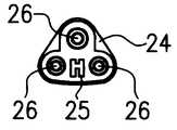
푸셔 플레이트(24), AH@ 형상의 단면으로 이루어진 가이드 포스트(guide post;25) 및 세개의 구동 로드(26)를 포함하는 피스톤 조립체(23)는 단부를 도시하는 도면이 도 10a와 측면도인 도 10b에 도시된다. 구동 로드(26)는 수용부(20) 내의 세개의 리세스와 맞물릴 수 있도록 배열되고, 가이드 포스트(25)는 수용부(20)의 후미로부터 연장되는 상응하는 형상의 제 4 리세스 내에 수용된다.The
사용시에, 밀봉제의 각각의 성분들을 함유하는 세개의 카트리지는 세개의 리세스 각각의 내부에 위치되고, 가이드 포스트(25)의 자유단은 수용부(20) 내의 리세스에 맞물린다. 가이드 포스트(25)가 구동 로드(26)보다 길기 때문에, 가이드 포스트는 가이드 로드(26)가 각각의 카트리지의 피스톤과 맞물리도록 각각의 리세스에 진입하기 전에 수용부(20)와 맞물릴 수 있다.In use, three cartridges containing respective components of the sealant are located inside each of the three recesses, and the free end of the
수용부의 핑거 그립(22)을 파지하고 피스톤 조립체의 플레이트(24)에 압력을 가함으로써, 상기 피스톤 조립체는 수용부(20) 내로 이동될 수 있고, 그 때문에, 세개의 구동 로드는 밀봉제의 성분들을 배관을 통해 ALuer@ 형 연결부(21)의 외부로 배출하도록 각각의 카트리지 내의 피스톤을 전진시킨다. 가이드 포스트(25)와 그 대응 리세스는 피스톤 조립체가 수용부(20) 내로 완전하게 전진된 후에 피스톤 조립체의 제거를 방지하는 협동 래치 수단으로 형성될 수 있다. 이는 장비가 단 한 번 사용된 후에 폐기되도록 한다.By gripping the
선택적으로, 밀봉제 성분의 2단계 적용이 바람직한 경우에는, 피스톤 조립체(23)는 수용부(20)로부터 제거될 수 있으므로, 제 1 작업에서는 하나 또는 두개의 밀봉제 성분이 분배될 수 있고, 그후 피스톤 조립체가 제거되고, 나머지 성분들의 모든 카트리지가 그들 각각의 리세스 내로 삽입된다. 그후, 피스톤 조립체(23)는 재위치되어 밀봉제의 나머지 성분 또는 성분들을 분배하도록 추가 분배 작업을 수행한다.Optionally, if a two-stage application of the sealant component is desired, the
이러한 제 2 실시예의 변형에서(도시되지 않음), 도 7에 도시된 것과 유사한 배관 배치가 적용될 수 있고, 수용부(20)의 선단에는 두개의 ALuer@ 형 연결부(21)가 제공될 수 있다.In a variant of this second embodiment (not shown), a piping arrangement similar to that shown in FIG. 7 can be applied, and two ALuer @ -
상기 카트리지들은 양호하게는 유리로 제조되지만, 사이클로-올레핀 코폴리머(cyclo-olefin copolymer)와 같은 임의의 적절하게 안정된 플라스틱 재료 또는 스테인리스 스틸로 제조될 수도 있다. 선택적으로, 수용부 내의 니들과 카트리지의 목부 단부에 관통할 수 있는 격벽을 제공하기 위해, 카트리지와 수용부에는 수루어형 및 암루어형 연결부 또는 다른 적절한 밀봉 연결부가 제공될 수 있다. 카트리지들의 직경은 각각의 피스톤의 동일한 축방향 이동이 카트리지들에 함유되는 성분들의 양에 비례하여 변위되도록 배열될 수 있다. 수용부 내의 가트리지들과 그들 각각의 리세스는 양호하게는 카트리지의 부정확한 삽입이 방지되도록 구성된다. 카트리지의 단면 형상은 상술된 실시예들에서는 원형이지만, 타원형, 삼각형, 정사각형, 직사각형 또는 다른 비원형 단면 형상이 피스톤의 형상에 대응되도록 사용될 수 있다는 것이 이해될 것이고, 분배기의 수용부 내의 리세스들은 카트리지의 잘못된 설치를 방지하도록 한가지 형상의 카트리지만을 수용하도록 구성될 수 있다.The cartridges are preferably made of glass, but may be made of any suitably stable plastic material such as cyclo-olefin copolymer or stainless steel. Optionally, the cartridge and the receptacle may be provided with water- and female-luer connections or other suitable sealing connections to provide a penetrating wall to the needle and the neck end of the cartridge. The diameter of the cartridges may be arranged such that the same axial movement of each piston is displaced in proportion to the amount of components contained in the cartridges. The cartridges and their respective recesses in the receptacle are preferably configured to prevent incorrect insertion of the cartridge. The cross-sectional shape of the cartridge is circular in the embodiments described above, but it will be understood that elliptical, triangular, square, rectangular or other non-circular cross-sectional shapes may be used to correspond to the shape of the piston, and the recesses in the receiver portion of the dispenser It can be configured to accommodate only one type of cartridge to prevent incorrect installation of the cartridge.
상기 카트리지들에는 카트리지의 개방된 제 2 단부로부터 피스톤의 이탈을 방지하기 위한 수단이 추가로 제공될 수 있다. 에틸렌 옥사이드 살균과 같은 일부 살균 절차에서, 카트리지들은 대기 압력보다 낮은 즉, 카트리지 내의 압력보다 낮은 주변 압력에 노출된다. 이러한 압력차는 피스톤을 카트리지의 제 2 단부쪽으로, 또는 제 2 단부의 외부로 이동시킨다. 카트리지들은 카트리지의 개방 단부를 향한 피스톤의 이동을 정지시키기 위한 접촉부를 갖는 트레이(tray)와 같은 캐리어 내에 장착될 수 있다. 선택적으로, 카트리지의 개방 단부에는 내부 립(lip)이 형성되고, 상기 립은 피스톤 위로 카트리지 내로 통과하도록 탄성적으로 변형될 수 있지만, 피스톤의 이탈은 방지한다. 다른 추가의 선택적인 예에서, 카트리지의 외부에 클립이 끼워질 수 있고, 상기 클립에는 카트리지로부터 피스톤이 이탈하는 것을 방지하기 위해 접촉부가 제공된다. 상기 클립은 분배기의 리세스 내로 카트리지를 삽입하기 전에 제거될 수 있거나, 부정확한 삽입을 방지할 수 있도록 리세스와 협동할 수 있다. 다른 실시예에서, 단일 클립은 단일 팩이 모든 밀봉제 성분들을 제공하고 임의의 복제가 불가능하도록 밀봉제 성분들 각각의 카트리지를 수용할 수 있다. 카트리지들은 분배기 내의 리세스들의 공간에 대응하는 배열로 클립 내에 고정될 수 있으므로, 카트리지들의 동시 장전이 용이해진다.The cartridges may further be provided with means for preventing release of the piston from the open second end of the cartridge. In some sterilization procedures, such as ethylene oxide sterilization, cartridges are exposed to ambient pressure below atmospheric pressure, ie below pressure within the cartridge. This pressure difference moves the piston towards the second end of the cartridge or out of the second end. The cartridges may be mounted in a carrier such as a tray having a contact for stopping the movement of the piston towards the open end of the cartridge. Optionally, an inner lip is formed at the open end of the cartridge, which can be elastically deformed to pass into the cartridge over the piston, but prevents the piston from escaping. In another further optional example, a clip can be fitted to the outside of the cartridge, the clip provided with a contact to prevent the piston from escaping from the cartridge. The clip may be removed before inserting the cartridge into the recess of the dispenser, or may cooperate with the recess to prevent incorrect insertion. In another embodiment, a single clip may receive a cartridge of each of the sealant components such that a single pack provides all sealant components and no replication is possible. The cartridges can be secured in the clip in an arrangement corresponding to the space of the recesses in the dispenser, thereby facilitating simultaneous loading of the cartridges.
본 발명은 생물학적 밀봉제를 적용 부위에 분배하기 위한 복수의 카트리지와 분배기를 포함하는 분배 장치 및 방법을 제공한다.
The present invention provides a dispensing device and method comprising a plurality of cartridges and dispensers for dispensing a biological sealant to an application site.
Claims (44)
Translated fromKoreanApplications Claiming Priority (2)
| Application Number | Priority Date | Filing Date | Title |
|---|---|---|---|
| GB0108207.2 | 2001-04-02 | ||
| GB0108207AGB2374014A (en) | 2001-04-02 | 2001-04-02 | Biological sealant storage and dispensing system |
Publications (2)
| Publication Number | Publication Date |
|---|---|
| KR20020077818A KR20020077818A (en) | 2002-10-14 |
| KR100821108B1true KR100821108B1 (en) | 2008-04-11 |
Family
ID=9912063
Family Applications (1)
| Application Number | Title | Priority Date | Filing Date |
|---|---|---|---|
| KR1020020017720AExpired - Fee RelatedKR100821108B1 (en) | 2001-04-02 | 2002-04-01 | Biological sealant storage and dispensing device |
Country Status (10)
| Country | Link |
|---|---|
| US (1) | US6874657B2 (en) |
| EP (1) | EP1247491B1 (en) |
| JP (1) | JP2002355317A (en) |
| KR (1) | KR100821108B1 (en) |
| AT (1) | ATE318545T1 (en) |
| AU (1) | AU784511B2 (en) |
| CA (1) | CA2380028C (en) |
| DE (1) | DE60209389T2 (en) |
| ES (1) | ES2259346T3 (en) |
| GB (1) | GB2374014A (en) |
Families Citing this family (44)
| Publication number | Priority date | Publication date | Assignee | Title |
|---|---|---|---|---|
| US8226598B2 (en)* | 1999-09-24 | 2012-07-24 | Tolmar Therapeutics, Inc. | Coupling syringe system and methods for obtaining a mixed composition |
| US6939329B1 (en)* | 1999-10-08 | 2005-09-06 | Harvest Technologies Corporation | Apparatus for holding and operating one or more syringes |
| US8206448B2 (en) | 2004-10-29 | 2012-06-26 | Spinal Restoration, Inc. | Injection of fibrin sealant using reconstituted components in spinal applications |
| US8419722B2 (en)* | 2004-10-29 | 2013-04-16 | Spinal Restoration, Inc. | Apparatus and method for injection of fibrin sealant in spinal applications |
| US7597687B2 (en)* | 2004-10-29 | 2009-10-06 | Spinal Restoration, Inc. | Injection of fibrin sealant including an anesthetic in spinal applications |
| AU2005279703B2 (en)* | 2004-08-31 | 2012-08-02 | Quikshot Packaging Pty Ltd | Beverage dispenser and method |
| NZ554144A (en)* | 2004-08-31 | 2009-07-31 | Quikshot Packaging Pty Ltd | Beverage dispenser and method |
| US20110213464A1 (en)* | 2004-10-29 | 2011-09-01 | Whitlock Steven I | Injection of fibrin sealant in the absence of corticosteroids in spinal applications |
| ES2398229T3 (en)* | 2005-01-12 | 2013-03-14 | Baxter International Inc. | Device and manual drive system for spraying a tissue sealant |
| DE102005041962B3 (en)* | 2005-09-03 | 2007-03-01 | Kettenbach Gmbh & Co. Kg | Cartridge for storing e.g. dental casting compound, has discharge opening whose height in axial direction of cylindrical pipe is larger than axial length of interlocking plunger that is arranged in pipe |
| US7722979B2 (en)* | 2005-10-14 | 2010-05-25 | Gm Global Technology Operations, Inc. | Fuel cells with hydrophobic diffusion medium |
| US8197545B2 (en)* | 2005-10-27 | 2012-06-12 | Depuy Spine, Inc. | Nucleus augmentation delivery device and technique |
| WO2007115039A2 (en)* | 2006-03-30 | 2007-10-11 | Valeritas, Llc | Multi-cartridge fluid delivery device |
| DE102006048180A1 (en)* | 2006-10-10 | 2008-04-17 | Tecpharma Licensing Ag | Injection device with a trigger lock with not inserted product container |
| US8287566B2 (en)* | 2007-10-26 | 2012-10-16 | Cohera Medical, Inc. | Spray devices and methods |
| CH699391A1 (en)* | 2008-08-19 | 2010-02-26 | Medmix Systems Ag | A dispensing assembly with a cartridge bag. |
| CH701225A1 (en)* | 2009-06-05 | 2010-12-15 | Medmix Systems Ag | Mixing apparatus for preparing a mixture of at least three components. |
| DE102009040705A1 (en)* | 2009-09-10 | 2011-03-24 | Heraeus Kulzer Gmbh | Device for semi-automatic proportioning of mixing components of dental masses, has pressing mechanism operating piston of peripheral cartouches together with piston of central cartouche, and static mixer attachable at outlet openings |
| US8486155B2 (en) | 2010-05-13 | 2013-07-16 | Ethicon Endo-Surgery, Inc. | Fistula repair plug having multiple layers |
| US8491526B2 (en)* | 2010-05-13 | 2013-07-23 | Ethicon Endo-Surgery, Inc. | Therapeutic cell applicator instrument with modular tips |
| US8568446B2 (en) | 2010-05-13 | 2013-10-29 | Ethicon Endo-Surgery, Inc. | Multi-chamber therapeutic cell applicator instrument |
| US8678238B2 (en)* | 2010-06-30 | 2014-03-25 | Actamax Surgical Materials, Llc | Self-contained hand-held yoke-connected device for dispensing a two-part adhesive aerosol |
| US20120000935A1 (en)* | 2010-06-30 | 2012-01-05 | E. I. Du Pont De Nemours And Company | Self-contained hand held yoke-connected device for dispensng a two-part adhesive aerosol |
| KR101869991B1 (en)* | 2010-08-11 | 2018-06-22 | 가부시키가이샤 고도부키 | Knock-type propelling container |
| IL217272A0 (en)* | 2011-12-29 | 2012-02-29 | Omrix Biopharmaceuticals | System for delivery of fluids and use thereof |
| US8919609B2 (en)* | 2012-01-10 | 2014-12-30 | Pac-Dent International, Inc. | Dental mixing device having an auto-aligning tip mixing tip |
| US11944519B2 (en) | 2012-01-18 | 2024-04-02 | Worldwide Innovative Healthcare, Inc. | Unbacked and modifiable tapes and skin dressings |
| AU2013209432B2 (en)* | 2012-01-18 | 2016-11-17 | Worldwide Innovative Healthcare, Inc. | Modifiable occlusive skin dressing |
| US8701938B2 (en)* | 2012-04-13 | 2014-04-22 | Michael Eric Darian | Applicator for extruding a semi-solid flowable material |
| WO2014002872A1 (en) | 2012-06-26 | 2014-01-03 | 凸版印刷株式会社 | Instrument for operating fluid injector using multi-microneedle device |
| EP2863810B1 (en) | 2012-08-24 | 2017-08-23 | St. Jude Medical Puerto Rico LLC | Bioadhesive mixing and delivery device |
| US9579685B2 (en) | 2012-09-21 | 2017-02-28 | Wilton Industries, Inc. | Coupler for decorating bag |
| WO2015153828A1 (en) | 2014-04-04 | 2015-10-08 | Hyperbranch Medical Technology, Inc. | Extended tip spray applicator for two-component surgical selant, and methods of use thereof |
| EP3282986B1 (en) | 2015-04-15 | 2021-07-21 | Celgentek Limited | System for delivery of biomaterials for fracture fixation |
| US10758935B2 (en) | 2015-12-02 | 2020-09-01 | Fishman Corporation | Multi-component gun |
| US11596741B2 (en)* | 2018-04-19 | 2023-03-07 | Ethicon, Inc. | Adapter manifold for multi-barrel syringe applicator |
| US10959714B2 (en) | 2018-04-19 | 2021-03-30 | Ethicon, Inc. | Dual syringe cartridge and housing |
| EP3833423B1 (en)* | 2018-10-02 | 2025-04-30 | Boston Scientific Scimed, Inc. | Devices for fluidization and delivering a powdered agent |
| EP4520387A3 (en)* | 2018-11-07 | 2025-06-04 | Baxter International, Inc. | Dual check valve one handed applicator |
| US20210121639A1 (en)* | 2019-10-28 | 2021-04-29 | Rowan University | Handheld printer for controlled mixing and delivery of multi-component polymers/biomaterials |
| US12161777B2 (en) | 2020-07-02 | 2024-12-10 | Davol Inc. | Flowable hemostatic suspension |
| US11739166B2 (en) | 2020-07-02 | 2023-08-29 | Davol Inc. | Reactive polysaccharide-based hemostatic agent |
| WO2022146917A1 (en) | 2020-12-28 | 2022-07-07 | Davol Inc. | Reactive dry powdered hemostatic materials comprising a protein and a multifunctionalized modified polyethylene glycol based crosslinking agent |
| US20220265938A1 (en)* | 2021-02-19 | 2022-08-25 | Ethicon, Inc. | Systems, devices and methods for dispensing biocompatible reactive formulations and controlling cross-linking of the reactive components of the biocompatible reactive formulations |
Citations (2)
| Publication number | Priority date | Publication date | Assignee | Title |
|---|---|---|---|---|
| US5415631A (en)* | 1992-04-03 | 1995-05-16 | United States Surgical Corporation | Endoscopic material delivery device |
| WO1996029370A2 (en)* | 1995-03-23 | 1996-09-26 | Focal, Inc. | Redox and photoinitiator systems for priming for improved adherence of gels to substrates |
Family Cites Families (20)
| Publication number | Priority date | Publication date | Assignee | Title |
|---|---|---|---|---|
| GB244998A (en)* | 1925-05-27 | 1925-12-31 | Jules Cournand | Improvements in or relating to syringes particularly utilisable for dental purposes |
| GB741604A (en)* | 1952-10-16 | 1955-12-07 | S & R J Everett & Co Ltd | Improvements relating to hypodermic syringes |
| US3517668A (en)* | 1967-10-16 | 1970-06-30 | Bio Neering Inc | Multiple dosage veterinary injection gun |
| US3767085A (en)* | 1971-08-02 | 1973-10-23 | J Cannon | Mixing syringe |
| US5199949A (en)* | 1991-03-08 | 1993-04-06 | Habley Medical Technology Corp. | Multiple pharmaceutical syringe |
| US5298023A (en)* | 1991-03-08 | 1994-03-29 | Habley Medical Technology Corporation | Multiple pharmaceutical dispenser with accumulator |
| DK68991D0 (en)* | 1991-04-17 | 1991-04-17 | Novo Nordisk As | HEADER |
| DK166691D0 (en)* | 1991-09-30 | 1991-09-30 | Unes As | MULTI-COMPONENT PROJECT |
| US5370273A (en)* | 1991-10-16 | 1994-12-06 | Minnesota Mining And Manufacturing Company | Multi-component applicator assembly |
| US5423752A (en)* | 1992-07-31 | 1995-06-13 | Habley Medical Technology Corporation | Variable proportion dispenser with cartridge replacement assembly |
| DE4223356A1 (en)* | 1992-07-16 | 1994-01-20 | Octapharma Ag Glarus | Multicomponent prod. applicator with head with component ducts - which are formed by rigid cannulae incorporated in head, coupled with front ends to respective hose lumens |
| US5584815A (en)* | 1993-04-02 | 1996-12-17 | Eli Lilly And Company | Multi-cartridge medication injection device |
| ZA941881B (en)* | 1993-04-02 | 1995-09-18 | Lilly Co Eli | Manifold medication injection apparatus and method |
| WO1996039212A2 (en)* | 1995-06-06 | 1996-12-12 | Quantic Biomedical Partners | Wound sealant preparation and application device and method |
| JP3024765U (en)* | 1995-11-17 | 1996-05-31 | 株式会社八光電機製作所 | Two chemical mixture spray nozzle |
| IL116815A0 (en)* | 1996-01-18 | 1996-05-14 | Hadasit Med Res Service | Carpule for an interligamentary syringe |
| JPH1119212A (en)* | 1997-07-07 | 1999-01-26 | Daikyo Seiko:Kk | Plastic container / syringe and manufacturing method thereof |
| US6042262A (en)* | 1997-07-29 | 2000-03-28 | Stryker Technologies Corportion | Apparatus for storing, mixing, and dispensing two-component bone cement |
| JPH1176277A (en)* | 1997-09-01 | 1999-03-23 | Fujihira Kogyo Kk | Injector for domestic animal |
| WO2000029041A1 (en) | 1998-11-18 | 2000-05-25 | Aventis Behring Gmbh | Stabilised protein preparations for a tissue adhesive |
- 2001
- 2001-04-02GBGB0108207Apatent/GB2374014A/ennot_activeWithdrawn
- 2002
- 2002-03-08ATAT02005163Tpatent/ATE318545T1/enactive
- 2002-03-08EPEP02005163Apatent/EP1247491B1/ennot_activeExpired - Lifetime
- 2002-03-08DEDE60209389Tpatent/DE60209389T2/ennot_activeExpired - Lifetime
- 2002-03-08ESES02005163Tpatent/ES2259346T3/ennot_activeExpired - Lifetime
- 2002-03-28AUAU29349/02Apatent/AU784511B2/ennot_activeCeased
- 2002-04-01KRKR1020020017720Apatent/KR100821108B1/ennot_activeExpired - Fee Related
- 2002-04-01JPJP2002098765Apatent/JP2002355317A/enactivePending
- 2002-04-01USUS10/109,631patent/US6874657B2/ennot_activeExpired - Lifetime
- 2002-04-02CACA2380028Apatent/CA2380028C/ennot_activeExpired - Fee Related
Patent Citations (2)
| Publication number | Priority date | Publication date | Assignee | Title |
|---|---|---|---|---|
| US5415631A (en)* | 1992-04-03 | 1995-05-16 | United States Surgical Corporation | Endoscopic material delivery device |
| WO1996029370A2 (en)* | 1995-03-23 | 1996-09-26 | Focal, Inc. | Redox and photoinitiator systems for priming for improved adherence of gels to substrates |
Also Published As
| Publication number | Publication date |
|---|---|
| DE60209389D1 (en) | 2006-04-27 |
| AU784511B2 (en) | 2006-04-13 |
| JP2002355317A (en) | 2002-12-10 |
| GB2374014A (en) | 2002-10-09 |
| EP1247491B1 (en) | 2006-03-01 |
| US20020161335A1 (en) | 2002-10-31 |
| CA2380028C (en) | 2010-08-17 |
| US6874657B2 (en) | 2005-04-05 |
| EP1247491A1 (en) | 2002-10-09 |
| GB0108207D0 (en) | 2001-05-23 |
| CA2380028A1 (en) | 2002-10-02 |
| AU2934902A (en) | 2002-10-03 |
| ATE318545T1 (en) | 2006-03-15 |
| KR20020077818A (en) | 2002-10-14 |
| DE60209389T2 (en) | 2006-12-21 |
| ES2259346T3 (en) | 2006-10-01 |
Similar Documents
| Publication | Publication Date | Title |
|---|---|---|
| KR100821108B1 (en) | Biological sealant storage and dispensing device | |
| EP1955727B1 (en) | Dispenser assembly for fibrin mixture | |
| EP1047464B1 (en) | Two component dispenser system | |
| EP0858775B1 (en) | Fibrin sealant applicator | |
| EP2105096A1 (en) | External mixer assembly | |
| US20030055384A1 (en) | Fibrin sealant applicator system | |
| JP2003526438A (en) | Dispenser for adhesive tissue sealants | |
| EP2362748B1 (en) | Apparatus for containing, transporting, and providing a material | |
| US10918790B2 (en) | Dual syringe with funnel feeding kit | |
| US20200360004A1 (en) | Dual syringe cartridge and housing | |
| EP1716877B1 (en) | Two component dispenser system | |
| CN116096307A (en) | Double syringe cartridge and housing | |
| EP1917914B1 (en) | External mixer assembly | |
| MXPA99002241A (en) | Applicator device for applying a multiple component fluid |
Legal Events
| Date | Code | Title | Description |
|---|---|---|---|
| PA0109 | Patent application | St.27 status event code:A-0-1-A10-A12-nap-PA0109 | |
| PG1501 | Laying open of application | St.27 status event code:A-1-1-Q10-Q12-nap-PG1501 | |
| R17-X000 | Change to representative recorded | St.27 status event code:A-3-3-R10-R17-oth-X000 | |
| PN2301 | Change of applicant | St.27 status event code:A-3-3-R10-R13-asn-PN2301 St.27 status event code:A-3-3-R10-R11-asn-PN2301 | |
| R17-X000 | Change to representative recorded | St.27 status event code:A-3-3-R10-R17-oth-X000 | |
| A201 | Request for examination | ||
| E13-X000 | Pre-grant limitation requested | St.27 status event code:A-2-3-E10-E13-lim-X000 | |
| P11-X000 | Amendment of application requested | St.27 status event code:A-2-2-P10-P11-nap-X000 | |
| P13-X000 | Application amended | St.27 status event code:A-2-2-P10-P13-nap-X000 | |
| PA0201 | Request for examination | St.27 status event code:A-1-2-D10-D11-exm-PA0201 | |
| R17-X000 | Change to representative recorded | St.27 status event code:A-3-3-R10-R17-oth-X000 | |
| PN2301 | Change of applicant | St.27 status event code:A-3-3-R10-R13-asn-PN2301 St.27 status event code:A-3-3-R10-R11-asn-PN2301 | |
| E701 | Decision to grant or registration of patent right | ||
| PE0701 | Decision of registration | St.27 status event code:A-1-2-D10-D22-exm-PE0701 | |
| GRNT | Written decision to grant | ||
| PR0701 | Registration of establishment | St.27 status event code:A-2-4-F10-F11-exm-PR0701 | |
| PR1002 | Payment of registration fee | St.27 status event code:A-2-2-U10-U11-oth-PR1002 Fee payment year number:1 | |
| PG1601 | Publication of registration | St.27 status event code:A-4-4-Q10-Q13-nap-PG1601 | |
| R18-X000 | Changes to party contact information recorded | St.27 status event code:A-5-5-R10-R18-oth-X000 | |
| PR1001 | Payment of annual fee | St.27 status event code:A-4-4-U10-U11-oth-PR1001 Fee payment year number:4 | |
| FPAY | Annual fee payment | Payment date:20120322 Year of fee payment:5 | |
| PR1001 | Payment of annual fee | St.27 status event code:A-4-4-U10-U11-oth-PR1001 Fee payment year number:5 | |
| FPAY | Annual fee payment | Payment date:20130320 Year of fee payment:6 | |
| PR1001 | Payment of annual fee | St.27 status event code:A-4-4-U10-U11-oth-PR1001 Fee payment year number:6 | |
| LAPS | Lapse due to unpaid annual fee | ||
| PC1903 | Unpaid annual fee | St.27 status event code:A-4-4-U10-U13-oth-PC1903 Not in force date:20140404 Payment event data comment text:Termination Category : DEFAULT_OF_REGISTRATION_FEE | |
| PC1903 | Unpaid annual fee | St.27 status event code:N-4-6-H10-H13-oth-PC1903 Ip right cessation event data comment text:Termination Category : DEFAULT_OF_REGISTRATION_FEE Not in force date:20140404 |