KR100820639B1 - Eye-based 3D interaction system and method and 3D eye tracking system and method - Google Patents
Eye-based 3D interaction system and method and 3D eye tracking system and methodDownload PDFInfo
- Publication number
- KR100820639B1 KR100820639B1KR1020060069988AKR20060069988AKR100820639B1KR 100820639 B1KR100820639 B1KR 100820639B1KR 1020060069988 AKR1020060069988 AKR 1020060069988AKR 20060069988 AKR20060069988 AKR 20060069988AKR 100820639 B1KR100820639 B1KR 100820639B1
- Authority
- KR
- South Korea
- Prior art keywords
- gaze
- image
- user
- sight
- depth
- Prior art date
- Legal status (The legal status is an assumption and is not a legal conclusion. Google has not performed a legal analysis and makes no representation as to the accuracy of the status listed.)
- Active
Links
Images


Classifications
- G—PHYSICS
- G06—COMPUTING OR CALCULATING; COUNTING
- G06T—IMAGE DATA PROCESSING OR GENERATION, IN GENERAL
- G06T7/00—Image analysis
- G06T7/40—Analysis of texture
- G—PHYSICS
- G06—COMPUTING OR CALCULATING; COUNTING
- G06F—ELECTRIC DIGITAL DATA PROCESSING
- G06F3/00—Input arrangements for transferring data to be processed into a form capable of being handled by the computer; Output arrangements for transferring data from processing unit to output unit, e.g. interface arrangements
- G06F3/01—Input arrangements or combined input and output arrangements for interaction between user and computer
- G06F3/011—Arrangements for interaction with the human body, e.g. for user immersion in virtual reality
- G06F3/013—Eye tracking input arrangements
- G—PHYSICS
- G06—COMPUTING OR CALCULATING; COUNTING
- G06F—ELECTRIC DIGITAL DATA PROCESSING
- G06F3/00—Input arrangements for transferring data to be processed into a form capable of being handled by the computer; Output arrangements for transferring data from processing unit to output unit, e.g. interface arrangements
- G—PHYSICS
- G06—COMPUTING OR CALCULATING; COUNTING
- G06V—IMAGE OR VIDEO RECOGNITION OR UNDERSTANDING
- G06V10/00—Arrangements for image or video recognition or understanding
- G06V10/40—Extraction of image or video features
- G—PHYSICS
- G06—COMPUTING OR CALCULATING; COUNTING
- G06V—IMAGE OR VIDEO RECOGNITION OR UNDERSTANDING
- G06V40/00—Recognition of biometric, human-related or animal-related patterns in image or video data
- G06V40/10—Human or animal bodies, e.g. vehicle occupants or pedestrians; Body parts, e.g. hands
- G06V40/18—Eye characteristics, e.g. of the iris
- G06V40/19—Sensors therefor
Landscapes
- Engineering & Computer Science (AREA)
- Theoretical Computer Science (AREA)
- General Physics & Mathematics (AREA)
- Physics & Mathematics (AREA)
- Human Computer Interaction (AREA)
- General Engineering & Computer Science (AREA)
- Multimedia (AREA)
- Ophthalmology & Optometry (AREA)
- Health & Medical Sciences (AREA)
- General Health & Medical Sciences (AREA)
- Computer Vision & Pattern Recognition (AREA)
- Position Input By Displaying (AREA)
- User Interface Of Digital Computer (AREA)
Abstract
Translated fromKoreanDescription
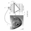
Translated fromKorean도 1은 본 발명에 따른 시선 기반 3차원 인터랙션 시스템의 구성을 보이는 개략도.1 is a schematic view showing the configuration of a gaze-based three-dimensional interaction system according to the present invention.
도 2는 본 발명의 실시예에 따라 구성된 시스템을 보이는 사진.2 is a photograph showing a system constructed in accordance with an embodiment of the present invention.
도 3 및 도 4는 2차원 영상 상의 객체의 위치 정보를 얻기 위한 시선방향을 설명하기 위한 개략도.3 and 4 are schematic diagrams for explaining a gaze direction for obtaining position information of an object on a 2D image.
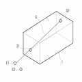
도 5 및 도 6은 3차원 영상 상의 객체의 위치 정보를 얻기 위한 시선방향 및 시선깊이를 설명하기 위한 개략도.5 and 6 are schematic diagrams for explaining the gaze direction and the gaze depth for obtaining position information of an object on a 3D image.
도 7은 사용자가 3차원 영상 상의 객체를 바라보는 상태를 보이는 개략도.7 is a schematic diagram showing a state where a user looks at an object on a 3D image.
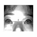
도 8은 도 7과 같은 상태에서 카메라로 찍은 사용자의 눈의 영상을 이용하여 시선 방향을 결정하는 방법을 설명하기 위한 개략도.FIG. 8 is a schematic diagram for explaining a method of determining a gaze direction using an image of a user's eyes taken with a camera in the same state as in FIG. 7; FIG.
도 9는 본 발명의 실시예에 따라 객체에 대한 사용자의 시선방향 결정 방법을 보이는 설명도.9 is an explanatory diagram showing a user's gaze direction determination method for an object according to an embodiment of the present invention;
도 10은 본 발명의 실시예에 따른 시선 방향 결정시, 눈 영상의 반사점과 적외선 광원의 관계, 시선, 동공의 중심점과 스크린 상의 시점과의 관계를 보이는 개 략도.10 is a schematic diagram showing a relationship between a reflection point of an eye image and an infrared light source, a line of sight, a center point of a pupil, and a viewpoint on a screen when determining a gaze direction according to an exemplary embodiment of the present invention.
도 11, 도 12 및 도 13은 횡방형 거리(c) 및 수직거리(h)에 따라 결정된 3차원 시선을 보이는 평면도, 측면도 및 사시도.11, 12 and 13 are a plan view, a side view, and a perspective view showing a three-dimensional line of sight determined according to the lateral distance c and the vertical distance h.
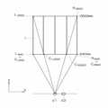
도 14 내지 도 16은 임의의 c 값에 대해 3차원 시선 방향을 도출하는 과정을 보이는 개략도.14 to 16 are schematic views showing a process of deriving a three-dimensional gaze direction for an arbitrary value of c '.
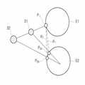
도 17 내지 도 19는 동공간의 간격에 따른 시선깊이 변화를 설명하기 위한 개략도.17 to 19 are schematic views for explaining the change in the line of sight depth according to the interval of the space.
도 20 및 도 21은 동공 간격에 따른 시선 깊이 변화를 보이는 설명도.20 and 21 are explanatory diagrams showing a line of sight depth change according to the pupil spacing.
도 22는 동공 간의 간격에 따른 시선 깊이의 변화를 보이는 그래프.22 is a graph showing the change in the line of sight depth according to the gap between the pupils.
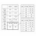
도 23은 입체 영상에서 같은 깊이를 갖는 영역을 12개의 영역으로 나눈 상태를 보이는 개략도.23 is a schematic diagram showing a state in which a region having the same depth is divided into 12 regions in a stereoscopic image.
도 24는 모니터와 사용자 간의 거리에 따른 영역별 PCD 값의 변화를 보이는 그래프.24 is a graph showing changes in PCD values for respective regions according to the distance between the monitor and the user.
도 25 및 도 26은 캘리브레이션을 위해 선정된 대상점의 위치를 보이는 개략도.25 and 26 are schematic diagrams showing the positions of the object points selected for calibration.
도 27은 캘리브레이션으로 구한 PCD 값을 이용하여 다른 깊이 값에서의 PCD 값을 보간법에 의해 구한 일예를 보이는 도표.Fig. 27 is a diagram showing an example in which the PCD values at different depth values are obtained by interpolation using the PCD values obtained by calibration.
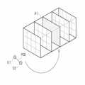
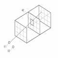
도 28 및 도 29는 시선의 방향 및 깊이를 이용하여 3차원 영상 상에 결정된시선 대상 영역을 보이는 개념도.28 and 29 are conceptual views showing a gaze target area determined on a three-dimensional image using the direction and depth of the gaze;
도 30 내지 도 32는 본 발명에 따른 3차원 시선 기반 인터랙션의 일실시예를 보이는 예시도.30 to 32 are exemplary views showing one embodiment of a three-dimensional gaze-based interaction according to the present invention.
본 발명은 시선 기반 3차원 인터랙션 시스템 및 방법에 관한 것으로, 특히 사용자의 눈 영상을 통해 사용자가 3차원 입체 디스플레이 화면상에 응시하는 점을 알아내기 위한 시선 기반 3차원 인터랙션 시스템 및 방법에 관한 것이다.The present invention relates to a gaze-based three-dimensional interaction system and method, and more particularly, to a gaze-based three-dimensional interaction system and method for finding a point that a user gazes on a three-dimensional stereoscopic display screen through an eye image of the user.
시선 추적 기술 및 시선 방향 추출 기술은 HCI(Human Computer Interaction) 분야에서 새로운 사용자 입력을 위해 각광받고 있는 기술로서, 손, 발의 움직임이 불편한 장애인이 컴퓨터를 사용할 수 있도록 개발되어 상용화되고 있다. 사람의 시선은 특별한 관심이나 생체 변화 등을 반영한다. 시선 추적을 이용하여 AUI (Attentive User Interface), 졸음운전 방지를 위한 안전 시스템(Safety System) 등의 개발 등 많은 분야에 대한 연구가 진행되고 있다.Gaze tracking technology and gaze direction extraction technology are in the spotlight for new user input in the field of human computer interaction (HCI), and have been developed and commercialized so that people with disabilities having hand and foot movements can use computers. Human gaze reflects special interests or biological changes. In the field of eye tracking, many fields such as development of AUI (Attentive User Interface) and safety system for preventing drowsy driving are being conducted.
종래 2차원 화면에 대한 시선 추적 기법은 눈 주위의 전극을 이용하는 EOG(Electrooculography) 방식, 광원의 위치에 따라 동공의 밝기가 변함을 이용하는 방식, 광원이 각막에서 반사되는 점을 이용하는 방식, 광원이 굴절률이 다른 눈의 여러 층을 통과할 때 나타나는 현상을 이용하는 방식,컨택트 렌즈(contact lens)를 사용하는 써치 코일(search coil) 방식이 있다. 또한 종래에는 자기 센서를 사용하여 추출된 머리 움직임 정보와 카메라를 이용하여 추출된 안구 홍채 및 동공 중심점 정보로부터 머리와 눈의 관계를 파악하여 시선을 추출하거나, 아날로 그 방식으로서 발광소자와 눈으로부터의 반사되는 빛을 입력받는 수광소자를 이용하여 수광소자의 위치와 시선에 따라 입력되는 빛의 변화로부터 시선을 예측한다.The conventional eye tracking method for a two-dimensional screen is an EOG (Electrooculography) method using an electrode around the eye, a method using a change in the brightness of the pupil depending on the position of the light source, a method using a point where the light source is reflected from the cornea, and the light source has a refractive index There is a method using a phenomenon appearing when passing through the different layers of the other eye, and a search coil method using a contact lens. Also, in the related art, eye gaze is extracted from eye movement iris and pupil center point information extracted by using a magnetic sensor and eye iris and pupil center point information extracted using a camera, or extracted from the light emitting element and eyes as an analog method. Using the light receiving element to receive the reflected light of the eye to predict the line of sight from the change of the light input according to the position and the line of sight of the light receiving element.
이와 같은 종래 2차원 시선 추적 방식은 사용자의 머리 위치를 알 수 없어 사용자의 머리를 고정시킨 상태에서 시선을 추적하거나 사용자의 머리 위치를 파악할 수 있는 별도의 장치를 이용해야하고, 2차원의 한계에 의해 정확도가 떨어진다. 또한, 종래 시선 추적 장치는 대량 제조가 이루어지지 않아 상당히 고가여서 주로 장애인용 입력 도구로서의 이용될 뿐 상용화 되고 있지 못하고 있는 실정이다.Such a conventional two-dimensional gaze tracking method can not know the position of the user's head and must use a separate device that can track the line of sight or determine the user's head position while the user's head is fixed, The accuracy is lowered. In addition, the conventional gaze tracking device is quite expensive because the mass production is not made, and is mainly used as an input tool for the disabled.
종래 머리 움직임 추적기(head tracker) 또는 스테레오 카메라 등을 이용해서 실제 사용자의 3차원 위치를 파악하고, 그로부터 3차원 시선 벡터를 추출하는 방식이 제안된 바 있으나, 이는 사용자가 머리를 자유롭게 움직이지 못하는 단점이 있다. 사용자의 얼굴과 눈의 특징점들을 추출하고, 추출된 특징점들을 기반으로 시선을 추적하는 종래 모델 기반 3차원 인터랙션 방식은 사용자가 인터랙션을 위한 별도의 장치를 부착할 필요가 없고, 머리도 어느 정도 움직이는 것이 허용되는 장점이 있으나, 카메라의 FOV (Field of View)에 얼굴 전체가 포함되어야 한다는 단점이 있다.Conventionally, a method of identifying a 3D position of an actual user and extracting a 3D gaze vector from the head using a head tracker or a stereo camera has been proposed, but this is a disadvantage in that the user does not move his head freely. There is this. The conventional model-based three-dimensional interaction method that extracts the feature points of the user's face and eyes and tracks the eyes based on the extracted feature points does not require the user to attach a separate device for interaction, and moves the head to some extent. There is an acceptable advantage, but the disadvantage is that the entire face must be included in the field of view (FOV) of the camera.
본 발명은 구성이 간단하며 저가로 구현할 수 있는 시선 기반 3차원 인터랙션 시스템 및 3차원 시선 추적 시스템을 제공하는데 그 목적이 있다. 특히, 본 발명은 사용자의 양안의 영상으로부터 시선의 방향 및 시선의 깊이 정보를 추출하고, 추출된 정보를 기반으로 3차원 입체 영상과의 인터랙션을 제공하는 시스템과 3차원 시선을 추적하기 위한 시스템을 제공한다.An object of the present invention is to provide a gaze-based three-dimensional interaction system and a three-dimensional gaze tracking system that can be easily implemented at low cost. In particular, the present invention provides a system for extracting the direction of the line of sight and the depth of the line of sight information from the images of both eyes of the user, and provides a system for tracking the three-dimensional line of sight based on the extracted information to provide.
또한 본 발명은 사용자의 눈 영상으로부터 시선의 방향 및 시선의 깊이 정보를 추출하여 3차원 입체 영상과 인터랙션 하는 방법 및 3차원 시선 추적 방법을 제공한다.In another aspect, the present invention provides a method for extracting the direction and the depth information of the gaze from the eye image of the user to interact with the 3D stereoscopic image and a 3D gaze tracking method.
본 발명에 따른 시선기반 3차원 인터랙션 시스템은 적어도 3차원 영상을 디스플레이하기 위한 디스플레이부; 상기 디스플레이부 양측에 정렬된 두 개의 광원; 상기 3차원 영상을 주시하는 사용자의 양안 영상-상기 양안 영상은 상기 광원에 의해 형성된 반사점들과 상기 양안 내 두 동공의 영상을 포함-을 획득하기 위한 영상 획득부; 상기 영상 획득부로부터 입력되는 상기 반사점과 상기 두 동공의 영상으로부터 시선방향과 시선깊이를 산출하기 위한 제1 신호처리부; 상기 산출된 시선방향 및 상기 시선깊이로부터 상기 3차원 영상 내 사용자가 주시하는 지점의 시선을 결정하기 위한 제2 신호처리부; 및 상기 결정된 시선에 따라 상기 사용자의 명령을 실행하기 위한 제3 신호처리부를 포함한다.A gaze-based three-dimensional interaction system according to the present invention includes a display unit for displaying at least a three-dimensional image; Two light sources arranged at both sides of the display unit; An image acquisition unit for acquiring a binocular image of the user who gazes at the 3D image, the binocular image including reflection points formed by the light source and images of two pupils in the binocular; A first signal processor configured to calculate a gaze direction and a gaze depth from the reflection points input from the image acquisition unit and the images of the two pupils; A second signal processor configured to determine a line of sight of a user's gaze in the 3D image from the calculated line of sight and the line of sight depth; And a third signal processor for executing the command of the user according to the determined line of sight.
본 발명의 시선기반 3차원 인터랙션 방법에 따르면 3차원 영상을 디스플레이하고, 상기 3차원 영상을 주시하는 사용자의 양눈에 광을 공급하고, 상기 3차원 영상을 주시하는 사용자의 양안 영상-상기 양안 영상은 상기 광원에 의해 형성된 반사점들과 상기 양안 내 두 동공의 영상을 포함-을 획득하고, 상기 획득된 영상 상의 상기 반사점과 상기 두 동공의 위치로부터 시선방향과 시선깊이를 산출하고, 상기 산출된 시선방향 및 상기 시선깊이로부터 상기 3차원 영상 내 사용자가 주시하는 지점의 시선을 결정하고, 상기 결정된 시선에 따라 상기 사용자의 명령을 실행 한다.According to the gaze-based three-dimensional interaction method of the present invention is to display a three-dimensional image, supply light to both eyes of the user looking at the three-dimensional image, the binocular image of the user looking at the three-dimensional image-the binocular image is A reflection point formed by the light source and an image of two pupils in both eyes is obtained, and a gaze direction and a gaze depth are calculated from the positions of the reflection points and the two pupils on the acquired image, and the calculated gaze direction And determining the line of sight of the point of view of the user in the 3D image from the line of sight depth, and executing the user's command according to the determined line of sight.
본 발명에 따른 3차원 시선 추적 시스템은 적어도 3차원 영상을 디스플레이하기 위한 디스플레이부; 상기 디스플레이부 양측에 정렬된 두 개의 광원; 상기 3차원 영상을 주시하는 사용자의 양안 영상-상기 양안 영상은 상기 광원에 의해 형성된 반사점들과 상기 양안 내 두 동공의 영상을 포함-을 획득하기 위한 영상 획득부; 상기 영상 획득부로부터 입력되는 상기 반사점과 상기 두 동공의 영상으로부터 시선방향과 시선깊이를 산출하기 위한 제1 신호처리부; 및 상기 산출된 시선방향 및 상기 시선깊이로부터 상기 3차원 영상 내 사용자가 주시하는 지점의 시선을 추적하기 위한 제2 신호처리부를 포함한다.3D gaze tracking system according to the present invention includes a display unit for displaying at least a three-dimensional image; Two light sources arranged at both sides of the display unit; An image acquisition unit for acquiring a binocular image of the user who gazes at the 3D image, the binocular image including reflection points formed by the light source and images of two pupils in the binocular; A first signal processor configured to calculate a gaze direction and a gaze depth from the reflection points input from the image acquisition unit and the images of the two pupils; And a second signal processor for tracking the gaze of a point gazed by the user in the 3D image from the calculated gaze direction and the gaze depth.
본 발명의 3차원 시선 추적 방법에 따르면, 3차원 영상을 디스플레이하고, 상기 3차원 영상을 주시하는 사용자의 양눈에 광을 공급하고, 상기 3차원 영상을 주시하는 사용자의 양안 영상-상기 양안 영상은 상기 광원에 의해 형성된 반사점들과 상기 양안 내 두 동공의 영상을 포함-을 획득하고, 상기 획득된 영상 상의 상기 반사점과 상기 두 동공의 위치로부터 시선방향과 시선깊이를 산출하고, 상기 산출된 시선방향 및 상기 시선깊이로부터 상기 3차원 영상 내 사용자가 주시하는 지점의 시선을 추적한다.According to the three-dimensional gaze tracking method of the present invention, the binocular image of the user for displaying a three-dimensional image, supplying light to both eyes of the user looking at the three-dimensional image, and watching the three-dimensional image is A reflection point formed by the light source and an image of two pupils in both eyes is obtained, and a gaze direction and a gaze depth are calculated from the positions of the reflection points and the two pupils on the acquired image, and the calculated gaze direction And a gaze of a gaze of a user's gaze in the 3D image from the gaze depth.
본 발명은 시선만을 이용하여 3차원 입체 영상 디스플레이 화면 영상의 임의의 위치 및 깊이에 있는 객체를 선택 및 포인팅 할 수 있는, 무안경식 3차원 시선 기반 인터랙션(interaction system) 시스템 및 인터랙션 방법 그리고 3차원 시선 추적 시스템 및 방법을 제공한다. 본 발명에서 지칭하는 인터랙션은 모니터 상의 커서 이동 및 포인팅을 포함하는 개념이다.The present invention provides an autostereoscopic 3D gaze-based interaction system and interaction method capable of selecting and pointing an object at an arbitrary position and depth of a 3D stereoscopic image display screen image using only a gaze and a 3D gaze Provide a tracking system and method. Interaction referred to in the present invention is a concept including cursor movement and pointing on the monitor.
도 1 및 도 2에 보이는 바와 같이 본 발명에 따른 3차원 시선 기반 인터랙션시스템(100)은 적어도 3차원 영상을 디스플레이하기 위한 디스플레이부(10), 상기 디스플레이부(10)의 양측에 정렬된 적어도 두개의 광원(11a, 11b), 3차원 영상을 주시하는 사용자의 양안에 광원(11a, 11b)에 의해 형성된 반사점과 양안 내 두 동공의 영상을 획득하기 위한 영상 획득부(12), 영상 획득부(12)로부터 입력되는 반사점과 두 동공의 영상으로부터 시선방향과 시선깊이를 산출하고, 산출된 시선방향 및 상기 시선깊이로부터 3차원 영상 내 사용자가 주시하는 지점의 시선을 결정하며, 결정된 시선에 따라 사용자의 명령을 실행하는 신호처리부(13)를 포함한다. 디스플레이부(10)는 3D 모니터로 구현되고, 신호처리부(13)는 다양한 형태의 PC(personal computer), 서버(server) 등으로 구현된다. 바람직하게, 광원(11a, 11b)은 적외선 LED(light emitting diode)이고, 영상 획득부(12)는 적외선 필터가 부착된 디지털 카메라(digital camera)이다. 신호처리부(13)는 시선방향과 시선깊이를 산출하기 위한 제1 신호처리부, 시선을 결정하기 위한 제2 신호처리부, 결정된 시선에 따라 사용자의 명령을 실행하는 제3 신호처리부로 분리되어 구성될 수 있다. 바람직하게 제1 신호처리부는, 한 쪽 눈의 영상에 포함된 두 반사점과 동공의 위치로부터 시선방향을 산출하고, 양안의 영상으로부터 얻은 두 동공간의 간격으로부터 상기 시선깊이를 산출한다. 제2 신호처리부는, 양안의 영상으로부터 얻은 두 동공간의 간격으로부터 같은 시선 깊이에 있는 영역을 선택하고, 시선깊이와 상 기 시선방향에 기초하여, 상기 선택된 영역 내에서 상기 사용자가 주시하는 지점의 시선을 결정한다.As shown in FIG. 1 and FIG. 2, the three-dimensional gaze-based
신호처리부(13)가 제3 신호 처리부를 구비하지 않고, 시선방향과 시선깊이를 산출하기 위한 제1 신호처리부와 시선을 결정하기 위한 제2 신호처리부를 구비할 경우, 도 1의 3차원 시선 기반 인터랙션시스템(100)은 시선 추적 시스템으로서 역할한다. 제3 신호처리부의 구비여부, 그 기능의 실행여부를 제외하면, 본 발명에 따른 3차원 시선 기반 인터랙션시스템 및 방법은 3차원 시선 추적 시스템 및 방법과 동일하므로, 본 명세서에서는 3차원 시선 기반 인터랙션시스템 및 방법을 중심으로 설명한다.When the
이하, 도 3 내지 도 32를 참조하여 본 발명을 보다 구체적으로 설명한다.Hereinafter, the present invention will be described in more detail with reference to FIGS. 3 to 32.
2차원 영상 상의 객체를 파악할 경우, 2차원 영상 디스플레이 장치(20)로부터 제공되는 2차원 영상 상의 모든 객체는 동일한 깊이를 가지기 때문에, 도 3 및 도 4에 보이는 바와 같이 사용자의 한 눈(E1 또는 E2)의 시선 방향만으로도 사용자가 2차원 영상 상의 객체(21)을 응시한다는 것을 파악할 수 있다. 즉, 도 4에서 사용자의 한눈(E1)의 시선방향 "G1" 또는 "G2"를 알면, 사용자가 2차원 영상 상의 객체 "21" 또는 "22"를 응시한다는 것을 알수 있다. 한편, 도 5 및 도 6에 도시한 바와 같이, 3차원 영상 디스플레이 장치 즉, 디스플레이부(10)로부터 제공되는 3차원 영상 상의 객체들(31 내지 35)은 위치에 따라 다른 깊이를 갖기 때문에 사용자의 양안 (E1, E2) 시선 정보를 알아야만 사용자가 응시하고 있는 객체가 어떤 것인지 파악할 수 있다. 도 6에서 도면부호 "G31a" 및 "G31b"는 각 눈(E1, E2)에서 객체 31을 응시하는 시선이고, "G32a" 및 "G32b"는 각 눈에서 객체 32를 응시하는 시선이며, "G33a" 및 "G33b"는 각 눈 에서 객체 33을 응시하는 시선이다. 이와 같이, 객체의 깊이가 다른 3차원 영상의 경우 양안의 시선에 의해 사용자가 바라보는 객체를 파악할 수 있다.When the object on the 2D image is grasped, since all objects on the 2D image provided from the 2D
도 7은 사용자가 디스플레이부(10)로부터 제공되는 3차원 영상 상의 객체(31)를 바라보는 상태를 개략적으로 보인다. 도 8은 도 7과 같은 상태에서 카메라로 찍은 사용자의 눈의 영상과 시선 방향 결정 방법을 설명하기 위한 개략도이다. 전술한 바와 같이, 3차원 시선 기반 인터랙션 시스템에 구비된 두 적외선 광원에 의해 도 8에 보인 바와 같이 사용자 눈의 영상에 두개의 반사점(glint)(g1, g2)이 보인다. g1은 바깥쪽 반사점이고, g2는 안쪽 반사점이다. 동공의 중심점(P)과 두 반사점(g1, g2)를 꼭지점으로 하는 삼각형을 고려할 때, 동공(P)에서 내린 수직선(h)과 바깥쪽 반사점(g1)에서 수직선(h)과 변g1g2의 교점 M에 이르는 거리(c)로부터 디스플레이부(10), 즉 스크린 상의 객체(31)을 향하는 사용자의 시선 방향을 결정할 수 있다. 도 9는 반사점(g1)에서 교점 M에 이르는 거리(이하, 횡방향 거리라 함)(c)와 수직거리(h)로부터 3차원 영상(I) 상의 객체(31)에 대한 사용자의 시선방향을 결정하는 방법을 보인다. 도 9에서 xc는 횡방향 거리(c)에 대응되고, yh는 동공의 중심점(P)에서 내린 수직거리 h에 대응된다. 도 10은 본 발명의 실시예에 따른 시선 방향 결정시, 눈 영상의 반사점과 적외선 광원(12a, 12b)의 관계, 시선(G), 동공의 중심점(P)과 스크린 상의 시점과의 관계를 나타낸다.FIG. 7 schematically shows a state where a user looks at an
도 11 및 도 12는 각각 상기 거리(c) 및 거리 (h)로부터 3차원 영상(I) 상에 사용자가 응시하는 횡방향으로의 시선 및 수직 방향 시선을 보이는 평면도 및 측면도이고, 도 13은 도면 11 및 도면 12 방법에 의해 최종적으로 3차원 시선의 방향을 보이는 사시도이다.11 and 12 are plan and side views showing a horizontal line of sight and a vertical line of sight gaze at a user on the three-dimensional image I from the distance c and the distance h, respectively, and FIG. It is a perspective view which shows the X direction of a three-dimensional "eye line" finally by the method of 11 and FIG.
도 14 내지 도 16은 임의의 횡방향 거리(c)로부터 시선의 횡방향 좌표값을 도출하는 과정을 보이는 개략도이다. 도 14는 사용자가 840 mm 및 2600 mm 떨어진 각 모니터의 왼쪽 및 오른쪽 끝점을 바라볼 때 시선의 방향과 이에 대응되는 횡방형 거리(c)가 달라짐을 보인다. 즉 840 mm 떨어진 모니터의 왼쪽 끝점(L840) 및 오른쪽 끝점(R840)에 대한 횡방향 거리(c)는 각각 "CL840", "CR840"이 되고, 2600 mm 떨어진 모니터의 왼쪽 끝점(L2600) 및 오른쪽 끝점(R2600)에 대한 횡방향 거리(c)는 각각 "CL2600", "CR2600"이 된다.14 to 16 are schematic views showing a process of deriving the lateral coordinate value of the gaze from an arbitrary lateral distance c. FIG. 14 shows that when the user looks at the left and right endpoints of each monitor 840 mm and 2600 mm apart, the direction of gaze and the corresponding lateral distance c are different. In other words, the lateral distance (c) to the left end point (L840 ) and the right end point (R840 ) of the
도 15 및 도 16에 보인 바와 같이 모니터와 사용자 사이의 거리가 각각 840 mm, 2600 mm일 때, 840 mm 떨어진 모니터 상의 한 점 A와, 2600 mm 떨어진 모니터 상에 존재하는 한 점 B가 사용자의 동일한 시선(G) 상에 있을 때, 눈 영상으로부터 추출된 횡방향 거리(c) 값은 동일하다. 예컨대, 점 A와 점 B의 횡방향 거리값 c가 모두 3.5가 된다. 미리 실시된 캘리브레이션(calbiration)에 의해 840 mm 떨어진 모니터의 왼쪽 끝점 L840 및 오른쪽 끝점 R840에 대응되는 c 값이 각각 0 및 10이고(도 15 참조), 2600 mm 떨어진 모니터의 왼쪽 끝점(L2600) 및 오른쪽 끝점 (R2600)에 대응되는 c 값이 각각 2.5 및 7.5인 것을 알았다면, 각 모니터의 가로 길이가 100일 때, 840 mm 및 2600 mm 떨어진 모니터 상에 존재하는 점 A 및 점 B의 좌표는 각각 35, 20이 된다. 이상에서 설명한 횡방향 거리(c)로부터 횡방향 좌표값을 구하는 방법과 동일한 방법으로, 수직거리(h)로부터 시선의 수직방향 좌표값도 구할 수 있다.As shown in FIGS. 15 and 16, when the distance between the monitor and the user is 840 mm and 2600 mm, respectively, a point A on the
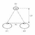
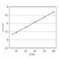
한편, 도 17에 보인 바와 같이, 2차원 영상 상의 객체(21)를 응시할 때는 객체(21)의 위치와 상관없이 시선 깊이는 동일하고 동공의 위치(Pa, Pb)만 변한다. 그러나, 도 18에 보인 바와 같이 3차원 영상 상의 객체들(31, 32)은 위치에 따라 시선 깊이가 달라져, 한쪽 눈(E1)의 시선을 따라 시선 방향을 결정하고, 양안(E1, E2)의 동공 간의 거리로부터 시선 깊이를 결정한다. 즉, 동일한 시선 방향에 있는 객체 31를 응시할때와 객체 32를 응시할 때 한쪽 눈(E2)의 동공 위치가 P2a에서 P2b로 변화함에 따라 양안의 동공간의 간격이 d1에서 d2로 변화한다. 도 19는 사용자의 눈 영상으로부터 양안의 동공 간격(d)을 측정하는 예를 보이는 사진이다. 바람직하게, 동공 간격(d)은 두 동공의 중심점 간의 거리이다. 도 20 및 도 21은 동공 간격에 따른 시선 깊이 변화를 비교하여 보이는 도면으로서, 동공 간격(d1 < d2)과 시선 깊이(L1 < L2) 간의 관계를 보이고 있다. 도 22는 동공 간의 간격(distance between pupil centers, 이하 PCD라 함)에 따른 시선 깊이의 변화를 보이는 그래프로서, 동공 간격(PCD)과 일정 시선 깊이가 선형적인 관계를 가짐을 보인다.As shown in FIG. 17, when gazing at the
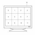
도 23에 보이는 바와 같이 디스플레이부(10) 상에 디스플레이되는 입체 영상에서 같은 깊이를 갖는 영역을 12개의 영역(0에서 11)으로 나눈 경우, 도 24에 보인 바와 같이 각 영역의 PCD 값은 모니터와 사용자간 거리의 함수로서 비교적 일정 범위내에 있다. 따라서, 모든 깊이에서 PCD 값을 구할 필요없이, 특정 깊이에서 구한 PCD 값을 이용한 보간으로 다른 깊이의 PCD 값을 구할 수 있다. 즉, 도 25에 보인 바와 같이, 캘리브레이션을 위해 3차원 영상에서 중심점(K1)과 중심점(K1)을 사이에 두고 대각선 상에 위치하는 꼭지점(K2 및 K3)을 사용자가 차례로 응시하고, 꼭지점(K2 및 K3)에 대해서는 c, h 및 PCD 값을 구하고, 중심점(K1)에 대해서는 PCD 값을 구한다. 도 25는 디스플레이부(10)와 사용자 사이의 거리가 840 mm인 경우이고, 도 26은 디스플레이부(10)와 사용자 사이의 거리가 2600 mm인 경우이다. 도 26과 같이 모니터가 원거리에 있는 경우, 모니터 크기에 대응되는 입체 영상은 상대적으로 작게 나타난다. 이는 원거리에 있는 물체가 상대적으로 작게 보이는 것과 동일한 원리이다. 디스플레이부(10)와 사용자 사이가 먼 경우에도, 도 26에 보인 바와 같이, 캘리브레이션을 위해 3차원 영상에서 중심점(K4)과 꼭지점(K5 및 K6)을 사용자가 차례로 응시하고, 꼭지점(K5 및 K6)에 대해서는 c, h 및 PCD 값을 구하고, 중심점(K4)에 대해서는 PCD 값을 구한다. 이와 같이, 840 mm 및 2600 mm 에서만 3개의 점에 대해 PCD를 구하고, 그 이외의 깊이 값에 대해서는 보간법에 의해 PCD 값을 구한다. 도 27은 2명 사용자를 대상으로 c, h, PCD의 캘리브레이션 값을 구하고, 캘리브레이션으로 구한 PCD 값을 이용하여 다른 깊이 값에서의 PCD 값을 보간법에 의해 구한 일예를 보인다. 이와 같이, 초기에 한번 사용자 캘리브레이 션에 의해 PCD 값을 얻고, PCD 에 대응되는 깊이 값을 구할 수 있다.As shown in FIG. 23, when the region having the same depth is divided into 12 regions (0 to 11) in the stereoscopic image displayed on the
도 28 및 도 29는 전술한 과정에 따라 구한 시선의 방향 및 깊이를 이용한 3차원 영상 상에 시선이 가리키는 대상 영역을 결정한 것을 보이는 개념도이다. 즉, 도 28에 보인 바와 같이 양안의 동공 중심점 간의 거리인 PCD를 구하고, PCD로부터 같은 시선의 깊이에 있는 영역(A1)을 선택한 다음, 도 29에 보인 바와 같이 3차원 시선의 방향과 깊이 값을 이용하여 최종적으로 3차원 영역 상에 시선이 가리키는 대상 영역(A2)을 결정한다.28 and 29 are conceptual views showing that the object region indicated by the line of sight is determined on a 3D image using the direction and depth of the line of sight obtained according to the above-described process. That is, as shown in FIG. 28, the PCD, which is the distance between the pupil and the center point of both eyes, is obtained, the area A1 is located at the same depth of view from the PCD, and then the direction and depth value of the three-dimensional gaze are shown as shown in FIG. Finally, the target area A2 indicated by the gaze on the three-dimensional area is determined.
도 30 내지 도 32는 본 발명에 따른 시선 기반 3차원 인터랙션의 일실시예로서 다트(dart)를 실시하는 예를 보이는 예시도이다. 도 30에 보이는 바와 같이 사용자의 양안이 시선 G1, G2로써 3차원 영상 상의 근거리에 있는 선택화살을 지정한 후, 시선을 변경시켜 시선 G3, G4로서 3차원 영상 상의 원거리에 있는 타켓을 지정함으로써 도 31에 보이는 바와 같이 선택된 화살이 타켓을 향하여 날아간다. 도면 32는 시선 기반 3차원 인터랙션이 진행되는 시스템(100)과 시선방향과 시선깊이 결정을 위한 과정을 모니터링하기 위한 모니터(15)를 함께 보이고 있다.30 to 32 are exemplary views showing an example of performing a dart as an embodiment of a gaze-based three-dimensional “interaction” according to the present invention. As shown in Fig. 30, both eyes of the user designate a selection arrow in the short distance on the 3D image as the eyes G1 and G2, and then change the line of sight so as to designate the target in the distance on the 3D image as the eyes G3 and G4. As shown, the selected arrow flies towards the target. FIG. 32 shows a
상술한 실시예는 본 발명의 원리를 응용한 다양한 실시예의 일부를 나타낸 것에 지나지 않음을 이해하여야 한다. 본 기술 분야에서 통상의 지식을 가진 자는 본 발명의 본질로부터 벗어남이 없이 여러 가지 변형 및 변경이 가능함을 명백히 알 수 있을 것이다.It is to be understood that the above-described embodiments are merely representative of some of the various embodiments to which the principles of the present invention are applied. It will be apparent to those skilled in the art that various modifications and variations can be made without departing from the spirit of the invention.
본 발명에 따른 시선 기반 3차원 인터랙션 시스템 및 3차원 시선 추적 시스 템은 기존 PC에 2개의 적외선 광원 및 카메라만을 추가하여 구현할 수 있다. 따라서, 제조 원가가 저렴하여 교육, 게임, 영화, 마케팅 분야와 같이 시선의 추적 및 기록, 사용자의 관심 기록 및 분석, 조사 등을 요구하는 다양한 분야에서 쉽게 응용될 수 있다. 또한, 본 발명은 사용자가 인터랙션을 위한 별도의 장치를 부착하지 않아도 됨으로 사용자가 보다 자유로운 상태에서 시스템을 이용할 수 있다.The gaze-based three-dimensional interaction system and the three-dimensional gaze tracking system according to the present invention can be implemented by adding only two infrared light sources and a camera to an existing PC. Therefore, since the manufacturing cost is low, it can be easily applied in various fields requiring tracking and recording of the line of sight, recording and analyzing the user's interest, and research such as education, games, movies, and marketing. In addition, the present invention does not require the user to attach a separate device for interaction, the user can use the system in a more free state.
또한 본 발명에 따른 시선 기반 3차원 인터랙션 시스템 및 방법 그리고 3차원 시선 추적 시스템 및 방법은 사용자의 한 쪽 눈의 영상을 이용하여 시선 방향을 결정하고 사용자 양안의 영상으로부터 얻은 동공 중심간의 간격을 이용하여 시선깊이를 결정함에 따라 신속하게 3차원 시선을 결정할 수 있다.In addition, the gaze-based three-dimensional interaction system and method and the three-dimensional gaze tracking system and method according to the present invention by using the image of one eye of the user to determine the direction of gaze and using the interval between the pupil centers obtained from the images of both eyes of the user By determining the line of sight depth, we can quickly determine the 3D line of sight.
Claims (16)
Translated fromKoreanPriority Applications (2)
| Application Number | Priority Date | Filing Date | Title |
|---|---|---|---|
| KR1020060069988AKR100820639B1 (en) | 2006-07-25 | 2006-07-25 | Eye-based 3D interaction system and method and 3D eye tracking system and method |
| US11/881,238US8032842B2 (en) | 2006-07-25 | 2007-07-25 | System and method for three-dimensional interaction based on gaze and system and method for tracking three-dimensional gaze |
Applications Claiming Priority (1)
| Application Number | Priority Date | Filing Date | Title |
|---|---|---|---|
| KR1020060069988AKR100820639B1 (en) | 2006-07-25 | 2006-07-25 | Eye-based 3D interaction system and method and 3D eye tracking system and method |
Publications (2)
| Publication Number | Publication Date |
|---|---|
| KR20080010041A KR20080010041A (en) | 2008-01-30 |
| KR100820639B1true KR100820639B1 (en) | 2008-04-10 |
Family
ID=39222239
Family Applications (1)
| Application Number | Title | Priority Date | Filing Date |
|---|---|---|---|
| KR1020060069988AActiveKR100820639B1 (en) | 2006-07-25 | 2006-07-25 | Eye-based 3D interaction system and method and 3D eye tracking system and method |
Country Status (2)
| Country | Link |
|---|---|
| US (1) | US8032842B2 (en) |
| KR (1) | KR100820639B1 (en) |
Cited By (9)
| Publication number | Priority date | Publication date | Assignee | Title |
|---|---|---|---|---|
| KR100976141B1 (en) | 2008-12-26 | 2010-08-16 | 광운대학교 산학협력단 | Image Position Control System and Method for Autostereoscopic Display Using Depth Camera |
| US8032842B2 (en) | 2006-07-25 | 2011-10-04 | Korea Institute Of Science & Technology | System and method for three-dimensional interaction based on gaze and system and method for tracking three-dimensional gaze |
| KR101165764B1 (en) | 2011-05-31 | 2012-07-18 | 주식회사 넥서스칩스 | Apparatus and method for automatically controlling convergence using eye-tracking |
| WO2013089369A1 (en)* | 2011-12-16 | 2013-06-20 | 에스케이플래닛 주식회사 | Apparatus and method for measuring the perceived depth of a three-dimensional image |
| CN105022498A (en)* | 2011-01-17 | 2015-11-04 | 联发科技股份有限公司 | Electronic device and method thereof |
| US9813597B2 (en) | 2015-09-21 | 2017-11-07 | Hyundai Motor Company | Gaze tracker and method for tracking gaze thereof |
| US9983685B2 (en) | 2011-01-17 | 2018-05-29 | Mediatek Inc. | Electronic apparatuses and methods for providing a man-machine interface (MMI) |
| US10595001B2 (en) | 2016-03-30 | 2020-03-17 | Industry-Academic Cooperation Foundation, Yonsei University | Apparatus for replaying content using gaze recognition and method thereof |
| US12399554B2 (en) | 2021-01-21 | 2025-08-26 | Samsung Electronics Co., Ltd. | Augmented reality device and method for detecting user's gaze |
Families Citing this family (60)
| Publication number | Priority date | Publication date | Assignee | Title |
|---|---|---|---|---|
| JP5564946B2 (en)* | 2007-09-20 | 2014-08-06 | 日本電気株式会社 | Video providing system and video providing method |
| US8581838B2 (en)* | 2008-12-19 | 2013-11-12 | Samsung Electronics Co., Ltd. | Eye gaze control during avatar-based communication |
| KR101564387B1 (en) | 2009-01-26 | 2015-11-06 | 토비 에이비 | Detection of gaze point assisted by optical reference signals |
| EP2549914B1 (en)* | 2010-03-22 | 2019-06-05 | Koninklijke Philips N.V. | System and method for tracking the point of gaze of an observer |
| US8966400B2 (en)* | 2010-06-07 | 2015-02-24 | Empire Technology Development Llc | User movement interpretation in computer generated reality |
| CN102339124A (en)* | 2010-07-22 | 2012-02-01 | 宏碁股份有限公司 | Method for controlling cursor |
| WO2012021967A1 (en)* | 2010-08-16 | 2012-02-23 | Tandemlaunch Technologies Inc. | System and method for analyzing three-dimensional (3d) media content |
| KR101697181B1 (en)* | 2010-09-07 | 2017-01-17 | 삼성전자주식회사 | Image processing apparatus and method using eye tracking of user |
| US9292973B2 (en) | 2010-11-08 | 2016-03-22 | Microsoft Technology Licensing, Llc | Automatic variable virtual focus for augmented reality displays |
| US9304319B2 (en) | 2010-11-18 | 2016-04-05 | Microsoft Technology Licensing, Llc | Automatic focus improvement for augmented reality displays |
| US8888287B2 (en) | 2010-12-13 | 2014-11-18 | Microsoft Corporation | Human-computer interface system having a 3D gaze tracker |
| US20130154913A1 (en)* | 2010-12-16 | 2013-06-20 | Siemens Corporation | Systems and methods for a gaze and gesture interface |
| US9213405B2 (en) | 2010-12-16 | 2015-12-15 | Microsoft Technology Licensing, Llc | Comprehension and intent-based content for augmented reality displays |
| US9153195B2 (en) | 2011-08-17 | 2015-10-06 | Microsoft Technology Licensing, Llc | Providing contextual personal information by a mixed reality device |
| WO2013028908A1 (en) | 2011-08-24 | 2013-02-28 | Microsoft Corporation | Touch and social cues as inputs into a computer |
| US8379981B1 (en) | 2011-08-26 | 2013-02-19 | Toyota Motor Engineering & Manufacturing North America, Inc. | Segmenting spatiotemporal data based on user gaze data |
| CA2750287C (en) | 2011-08-29 | 2012-07-03 | Microsoft Corporation | Gaze detection in a see-through, near-eye, mixed reality display |
| US9323325B2 (en)* | 2011-08-30 | 2016-04-26 | Microsoft Technology Licensing, Llc | Enhancing an object of interest in a see-through, mixed reality display device |
| US8879801B2 (en) | 2011-10-03 | 2014-11-04 | Qualcomm Incorporated | Image-based head position tracking method and system |
| US9503713B2 (en) | 2011-11-02 | 2016-11-22 | Intuitive Surgical Operations, Inc. | Method and system for stereo gaze tracking |
| KR101471488B1 (en)* | 2012-03-23 | 2014-12-10 | 경북대학교 산학협력단 | Device and Method for Tracking Sight Line |
| JP5949319B2 (en)* | 2012-08-21 | 2016-07-06 | 富士通株式会社 | Gaze detection apparatus and gaze detection method |
| EP2709060B1 (en)* | 2012-09-17 | 2020-02-26 | Apple Inc. | Method and an apparatus for determining a gaze point on a three-dimensional object |
| US20140118243A1 (en)* | 2012-10-25 | 2014-05-01 | University Of Seoul Industry Cooperation Foundation | Display section determination |
| US9179833B2 (en) | 2013-02-28 | 2015-11-10 | Carl Zeiss Meditec, Inc. | Systems and methods for improved ease and accuracy of gaze tracking |
| RU2013118993A (en)* | 2013-04-23 | 2013-09-10 | Александр Николаевич Лукоянов | ADAPTIVE VIDEO IMPLEMENTATION METHOD |
| EP3103058A1 (en)* | 2014-02-04 | 2016-12-14 | Fraunhofer-Gesellschaft zur Förderung der angewandten Forschung e.V. | Hough processor |
| KR101673694B1 (en)* | 2014-11-10 | 2016-11-07 | 현대자동차주식회사 | Gaze tracking apparatus and method for detecting glint thereof |
| GB2539009A (en) | 2015-06-03 | 2016-12-07 | Tobii Ab | Gaze detection method and apparatus |
| US10607401B2 (en) | 2015-06-03 | 2020-03-31 | Tobii Ab | Multi line trace gaze to object mapping for determining gaze focus targets |
| TWI694604B (en) | 2015-07-23 | 2020-05-21 | 光澄科技股份有限公司 | Light detector |
| US10861888B2 (en) | 2015-08-04 | 2020-12-08 | Artilux, Inc. | Silicon germanium imager with photodiode in trench |
| US10761599B2 (en) | 2015-08-04 | 2020-09-01 | Artilux, Inc. | Eye gesture tracking |
| US10707260B2 (en) | 2015-08-04 | 2020-07-07 | Artilux, Inc. | Circuit for operating a multi-gate VIS/IR photodiode |
| CN108028258B (en) | 2015-08-04 | 2022-06-21 | 光程研创股份有限公司 | Germanium-silicon photosensitive equipment |
| EP3783656B1 (en) | 2015-08-27 | 2023-08-23 | Artilux Inc. | Wide spectrum optical sensor |
| US10016130B2 (en) | 2015-09-04 | 2018-07-10 | University Of Massachusetts | Eye tracker system and methods for detecting eye parameters |
| US10418407B2 (en) | 2015-11-06 | 2019-09-17 | Artilux, Inc. | High-speed light sensing apparatus III |
| US10886309B2 (en) | 2015-11-06 | 2021-01-05 | Artilux, Inc. | High-speed light sensing apparatus II |
| US10739443B2 (en) | 2015-11-06 | 2020-08-11 | Artilux, Inc. | High-speed light sensing apparatus II |
| US10741598B2 (en) | 2015-11-06 | 2020-08-11 | Atrilux, Inc. | High-speed light sensing apparatus II |
| US10254389B2 (en) | 2015-11-06 | 2019-04-09 | Artilux Corporation | High-speed light sensing apparatus |
| KR101780669B1 (en)* | 2016-11-16 | 2017-09-21 | (주)스코넥엔터테인먼트 | binocular capturing device using single camera |
| US10481599B2 (en) | 2017-07-24 | 2019-11-19 | Motorola Solutions, Inc. | Methods and systems for controlling an object using a head-mounted display |
| CN114924651A (en) | 2017-09-29 | 2022-08-19 | 苹果公司 | Gaze-Based User Interaction |
| WO2019117350A1 (en)* | 2017-12-14 | 2019-06-20 | 삼성전자 주식회사 | Staring distance determination method and device |
| US10777692B2 (en) | 2018-02-23 | 2020-09-15 | Artilux, Inc. | Photo-detecting apparatus and photo-detecting method thereof |
| US11105928B2 (en) | 2018-02-23 | 2021-08-31 | Artilux, Inc. | Light-sensing apparatus and light-sensing method thereof |
| CN114335030A (en) | 2018-04-08 | 2022-04-12 | 奥特逻科公司 | Optical detection device |
| US10854770B2 (en) | 2018-05-07 | 2020-12-01 | Artilux, Inc. | Avalanche photo-transistor |
| US10969877B2 (en) | 2018-05-08 | 2021-04-06 | Artilux, Inc. | Display apparatus |
| US11314396B2 (en) | 2018-05-09 | 2022-04-26 | Apple Inc. | Selecting a text input field using eye gaze |
| CN110547759B (en)* | 2018-05-31 | 2024-08-16 | 托比股份公司 | Robust convergence signal |
| US11478318B2 (en) | 2018-12-28 | 2022-10-25 | Verb Surgical Inc. | Methods for actively engaging and disengaging teleoperation of a surgical robotic system |
| SE543144C2 (en)* | 2019-05-15 | 2020-10-13 | Tobii Ab | Method and system for dwell-less, hands-free interaction with a selectable object |
| US11204640B2 (en)* | 2019-05-17 | 2021-12-21 | Verb Surgical Inc. | Methods for determining if teleoperation should be disengaged based on the user's gaze |
| US11337767B2 (en) | 2019-05-17 | 2022-05-24 | Verb Surgical Inc. | Interlock mechanisms to disengage and engage a teleoperation mode |
| US11786694B2 (en) | 2019-05-24 | 2023-10-17 | NeuroLight, Inc. | Device, method, and app for facilitating sleep |
| CN114795102B (en)* | 2021-01-27 | 2025-04-25 | 京东方科技集团股份有限公司 | Gaze depth acquisition method and device, display device, and storage medium |
| SE2350314A1 (en)* | 2023-03-21 | 2024-09-22 | Tobii Ab | An eye tracking system and methods of using an eye tracking system |
Citations (5)
| Publication number | Priority date | Publication date | Assignee | Title |
|---|---|---|---|---|
| JPH1091325A (en) | 1996-09-13 | 1998-04-10 | Toshiba Corp | Eye gaze detection system |
| KR20020059651A (en)* | 1999-10-29 | 2002-07-13 | 마이크로비젼, 인코퍼레이티드 | Personal display with vision tracking |
| US6456262B1 (en) | 2000-05-09 | 2002-09-24 | Intel Corporation | Microdisplay with eye gaze detection |
| KR20040027764A (en)* | 2004-03-03 | 2004-04-01 | 학교법인 한국정보통신학원 | A method for manipulating a terminal using user's glint, and an apparatus |
| JP2004188017A (en) | 2002-12-12 | 2004-07-08 | Canon Inc | Eye gaze detection device |
Family Cites Families (18)
| Publication number | Priority date | Publication date | Assignee | Title |
|---|---|---|---|---|
| US5309185A (en)* | 1992-06-08 | 1994-05-03 | Harper Gilberto B | Apparatus and method for objective quantitative assessment of human ocular coordination |
| US5500671A (en)* | 1994-10-25 | 1996-03-19 | At&T Corp. | Video conference system and method of providing parallax correction and a sense of presence |
| US5550602A (en)* | 1994-11-09 | 1996-08-27 | Johannes Braeuning | Apparatus and method for examining visual functions |
| US5933210A (en)* | 1995-03-06 | 1999-08-03 | Ron; Samuel | Ophthalmological method and instrument for producing dichoptic stimuli |
| US6847336B1 (en)* | 1996-10-02 | 2005-01-25 | Jerome H. Lemelson | Selectively controllable heads-up display system |
| US5963300A (en)* | 1998-02-17 | 1999-10-05 | Amt Technologies, Corp. | Ocular biometer |
| US6393136B1 (en)* | 1999-01-04 | 2002-05-21 | International Business Machines Corporation | Method and apparatus for determining eye contact |
| JP2002093777A (en) | 2000-07-11 | 2002-03-29 | Nisshinbo Ind Inc | Dry etching equipment |
| DE10103922A1 (en)* | 2001-01-30 | 2002-08-01 | Physoptics Opto Electronic Gmb | Interactive data viewing and operating system |
| TWI289437B (en)* | 2002-01-04 | 2007-11-11 | Vision Optic Co Ltd | Optometry apparatus, optometry method, optometry server and computer readable recording medium |
| US7309128B2 (en)* | 2002-09-20 | 2007-12-18 | Centrofuse Technologies, Llc | Automated stereocampimeter and related method for improved measurement of the visual field |
| US7306337B2 (en)* | 2003-03-06 | 2007-12-11 | Rensselaer Polytechnic Institute | Calibration-free gaze tracking under natural head movement |
| CA2545202C (en)* | 2003-11-14 | 2014-01-14 | Queen's University At Kingston | Method and apparatus for calibration-free eye tracking |
| US7963652B2 (en)* | 2003-11-14 | 2011-06-21 | Queen's University At Kingston | Method and apparatus for calibration-free eye tracking |
| US20050105044A1 (en)* | 2003-11-14 | 2005-05-19 | Laurence Warden | Lensometers and wavefront sensors and methods of measuring aberration |
| CA2576026A1 (en)* | 2004-08-03 | 2006-02-09 | Silverbrook Research Pty Ltd | Walk-up printing |
| US7878910B2 (en)* | 2005-09-13 | 2011-02-01 | Igt | Gaming machine with scanning 3-D display system |
| KR100820639B1 (en) | 2006-07-25 | 2008-04-10 | 한국과학기술연구원 | Eye-based 3D interaction system and method and 3D eye tracking system and method |
- 2006
- 2006-07-25KRKR1020060069988Apatent/KR100820639B1/enactiveActive
- 2007
- 2007-07-25USUS11/881,238patent/US8032842B2/enactiveActive
Patent Citations (5)
| Publication number | Priority date | Publication date | Assignee | Title |
|---|---|---|---|---|
| JPH1091325A (en) | 1996-09-13 | 1998-04-10 | Toshiba Corp | Eye gaze detection system |
| KR20020059651A (en)* | 1999-10-29 | 2002-07-13 | 마이크로비젼, 인코퍼레이티드 | Personal display with vision tracking |
| US6456262B1 (en) | 2000-05-09 | 2002-09-24 | Intel Corporation | Microdisplay with eye gaze detection |
| JP2004188017A (en) | 2002-12-12 | 2004-07-08 | Canon Inc | Eye gaze detection device |
| KR20040027764A (en)* | 2004-03-03 | 2004-04-01 | 학교법인 한국정보통신학원 | A method for manipulating a terminal using user's glint, and an apparatus |
Cited By (12)
| Publication number | Priority date | Publication date | Assignee | Title |
|---|---|---|---|---|
| US8032842B2 (en) | 2006-07-25 | 2011-10-04 | Korea Institute Of Science & Technology | System and method for three-dimensional interaction based on gaze and system and method for tracking three-dimensional gaze |
| KR100976141B1 (en) | 2008-12-26 | 2010-08-16 | 광운대학교 산학협력단 | Image Position Control System and Method for Autostereoscopic Display Using Depth Camera |
| CN105022498A (en)* | 2011-01-17 | 2015-11-04 | 联发科技股份有限公司 | Electronic device and method thereof |
| US9983685B2 (en) | 2011-01-17 | 2018-05-29 | Mediatek Inc. | Electronic apparatuses and methods for providing a man-machine interface (MMI) |
| CN105022498B (en)* | 2011-01-17 | 2018-06-19 | 联发科技股份有限公司 | Electronic device and method thereof |
| KR101165764B1 (en) | 2011-05-31 | 2012-07-18 | 주식회사 넥서스칩스 | Apparatus and method for automatically controlling convergence using eye-tracking |
| WO2012165718A1 (en)* | 2011-05-31 | 2012-12-06 | 주식회사 넥서스칩스 | Automatic convergence control apparatus using eye-tracking and method for same |
| WO2013089369A1 (en)* | 2011-12-16 | 2013-06-20 | 에스케이플래닛 주식회사 | Apparatus and method for measuring the perceived depth of a three-dimensional image |
| US9538166B2 (en) | 2011-12-16 | 2017-01-03 | Sk Planet Co., Ltd. | Apparatus and method for measuring depth of the three-dimensional image |
| US9813597B2 (en) | 2015-09-21 | 2017-11-07 | Hyundai Motor Company | Gaze tracker and method for tracking gaze thereof |
| US10595001B2 (en) | 2016-03-30 | 2020-03-17 | Industry-Academic Cooperation Foundation, Yonsei University | Apparatus for replaying content using gaze recognition and method thereof |
| US12399554B2 (en) | 2021-01-21 | 2025-08-26 | Samsung Electronics Co., Ltd. | Augmented reality device and method for detecting user's gaze |
Also Published As
| Publication number | Publication date |
|---|---|
| US20080181452A1 (en) | 2008-07-31 |
| US8032842B2 (en) | 2011-10-04 |
| KR20080010041A (en) | 2008-01-30 |
Similar Documents
| Publication | Publication Date | Title |
|---|---|---|
| KR100820639B1 (en) | Eye-based 3D interaction system and method and 3D eye tracking system and method | |
| US11157725B2 (en) | Gesture-based casting and manipulation of virtual content in artificial-reality environments | |
| CN109564472B (en) | Method, medium, and system for selecting an interaction method with a virtual object | |
| CN114730094B (en) | Artificial reality system with varifocal display of artificial reality content | |
| US9829973B2 (en) | Eye gaze determination | |
| EP1691670B1 (en) | Method and apparatus for calibration-free eye tracking | |
| US9953214B2 (en) | Real time eye tracking for human computer interaction | |
| CN104603673B (en) | Head-mounted system and the method for being calculated using head-mounted system and rendering digital image stream | |
| US20200363867A1 (en) | Blink-based calibration of an optical see-through head-mounted display | |
| EP3570771B1 (en) | Augmented reality for radiation dose monitoring | |
| Hennessey et al. | Noncontact binocular eye-gaze tracking for point-of-gaze estimation in three dimensions | |
| US20170263017A1 (en) | System and method for tracking gaze position | |
| US10896545B1 (en) | Near eye display interface for artificial reality applications | |
| KR101892735B1 (en) | Apparatus and Method for Intuitive Interaction | |
| WO2018076202A1 (en) | Head-mounted display device that can perform eye tracking, and eye tracking method | |
| US20250199604A1 (en) | Mixed reality interaction with eye-tracking techniques | |
| JPWO2020016970A1 (en) | Information processing equipment, information processing methods, and programs | |
| KR20200096002A (en) | Apparatus and method for measuring distance between pupil centers | |
| Lim et al. | Development of gaze tracking interface for controlling 3D contents | |
| Deng | Multimodal interactions in virtual environments using eye tracking and gesture control. | |
| KR101733519B1 (en) | Apparatus and method for 3-dimensional display | |
| Changyuan et al. | The line of sight to estimate method based on stereo vision | |
| KR101145454B1 (en) | Method, system and computer-readable recording medium for controlling content using infrared marker | |
| WO2024047990A1 (en) | Information processing device | |
| Mokatren | Exploring the Potential Use of Mobile Eye Tracking Technology as an Intuitive Pointing Device |
Legal Events
| Date | Code | Title | Description |
|---|---|---|---|
| A201 | Request for examination | ||
| PA0109 | Patent application | Patent event code:PA01091R01D Comment text:Patent Application Patent event date:20060725 | |
| PA0201 | Request for examination | ||
| E902 | Notification of reason for refusal | ||
| PE0902 | Notice of grounds for rejection | Comment text:Notification of reason for refusal Patent event date:20070927 Patent event code:PE09021S01D | |
| PG1501 | Laying open of application | ||
| E701 | Decision to grant or registration of patent right | ||
| PE0701 | Decision of registration | Patent event code:PE07011S01D Comment text:Decision to Grant Registration Patent event date:20080324 | |
| GRNT | Written decision to grant | ||
| PR0701 | Registration of establishment | Comment text:Registration of Establishment Patent event date:20080402 Patent event code:PR07011E01D | |
| PR1002 | Payment of registration fee | Payment date:20080403 End annual number:3 Start annual number:1 | |
| PG1601 | Publication of registration | ||
| PR1001 | Payment of annual fee | Payment date:20110404 Start annual number:4 End annual number:4 | |
| FPAY | Annual fee payment | Payment date:20120330 Year of fee payment:5 | |
| PR1001 | Payment of annual fee | Payment date:20120330 Start annual number:5 End annual number:5 | |
| FPAY | Annual fee payment | Payment date:20130401 Year of fee payment:6 | |
| PR1001 | Payment of annual fee | Payment date:20130401 Start annual number:6 End annual number:6 | |
| FPAY | Annual fee payment | Payment date:20160401 Year of fee payment:9 | |
| PR1001 | Payment of annual fee | Payment date:20160401 Start annual number:9 End annual number:9 | |
| FPAY | Annual fee payment | Payment date:20170403 Year of fee payment:10 | |
| PR1001 | Payment of annual fee | Payment date:20170403 Start annual number:10 End annual number:10 | |
| FPAY | Annual fee payment | Payment date:20180403 Year of fee payment:11 | |
| PR1001 | Payment of annual fee | Payment date:20180403 Start annual number:11 End annual number:11 | |
| FPAY | Annual fee payment | Payment date:20190401 Year of fee payment:12 | |
| PR1001 | Payment of annual fee | Payment date:20190401 Start annual number:12 End annual number:12 | |
| PR1001 | Payment of annual fee | Payment date:20200401 Start annual number:13 End annual number:13 | |
| PR1001 | Payment of annual fee | Payment date:20210401 Start annual number:14 End annual number:14 | |
| PR1001 | Payment of annual fee | Payment date:20230321 Start annual number:16 End annual number:16 | |
| PR1001 | Payment of annual fee | Payment date:20250324 Start annual number:18 End annual number:18 |