KR100819253B1 - Backlight Units for Mobile Terminals - Google Patents
Backlight Units for Mobile TerminalsDownload PDFInfo
- Publication number
- KR100819253B1 KR100819253B1KR1020060067496AKR20060067496AKR100819253B1KR 100819253 B1KR100819253 B1KR 100819253B1KR 1020060067496 AKR1020060067496 AKR 1020060067496AKR 20060067496 AKR20060067496 AKR 20060067496AKR 100819253 B1KR100819253 B1KR 100819253B1
- Authority
- KR
- South Korea
- Prior art keywords
- guide plate
- light
- light guide
- backlight unit
- disposed
- Prior art date
- Legal status (The legal status is an assumption and is not a legal conclusion. Google has not performed a legal analysis and makes no representation as to the accuracy of the status listed.)
- Expired - Fee Related
Links
Images


Classifications
- G—PHYSICS
- G02—OPTICS
- G02F—OPTICAL DEVICES OR ARRANGEMENTS FOR THE CONTROL OF LIGHT BY MODIFICATION OF THE OPTICAL PROPERTIES OF THE MEDIA OF THE ELEMENTS INVOLVED THEREIN; NON-LINEAR OPTICS; FREQUENCY-CHANGING OF LIGHT; OPTICAL LOGIC ELEMENTS; OPTICAL ANALOGUE/DIGITAL CONVERTERS
- G02F1/00—Devices or arrangements for the control of the intensity, colour, phase, polarisation or direction of light arriving from an independent light source, e.g. switching, gating or modulating; Non-linear optics
- G02F1/01—Devices or arrangements for the control of the intensity, colour, phase, polarisation or direction of light arriving from an independent light source, e.g. switching, gating or modulating; Non-linear optics for the control of the intensity, phase, polarisation or colour
- G02F1/13—Devices or arrangements for the control of the intensity, colour, phase, polarisation or direction of light arriving from an independent light source, e.g. switching, gating or modulating; Non-linear optics for the control of the intensity, phase, polarisation or colour based on liquid crystals, e.g. single liquid crystal display cells
- G02F1/133—Constructional arrangements; Operation of liquid crystal cells; Circuit arrangements
- G02F1/1333—Constructional arrangements; Manufacturing methods
- G02F1/1335—Structural association of cells with optical devices, e.g. polarisers or reflectors
- G—PHYSICS
- G02—OPTICS
- G02B—OPTICAL ELEMENTS, SYSTEMS OR APPARATUS
- G02B6/00—Light guides; Structural details of arrangements comprising light guides and other optical elements, e.g. couplings
- G02B6/0001—Light guides; Structural details of arrangements comprising light guides and other optical elements, e.g. couplings specially adapted for lighting devices or systems
- G02B6/0011—Light guides; Structural details of arrangements comprising light guides and other optical elements, e.g. couplings specially adapted for lighting devices or systems the light guides being planar or of plate-like form
- G02B6/0033—Means for improving the coupling-out of light from the light guide
- G02B6/0058—Means for improving the coupling-out of light from the light guide varying in density, size, shape or depth along the light guide
- G02B6/006—Means for improving the coupling-out of light from the light guide varying in density, size, shape or depth along the light guide to produce indicia, symbols, texts or the like
- G—PHYSICS
- G02—OPTICS
- G02B—OPTICAL ELEMENTS, SYSTEMS OR APPARATUS
- G02B6/00—Light guides; Structural details of arrangements comprising light guides and other optical elements, e.g. couplings
- G02B6/0001—Light guides; Structural details of arrangements comprising light guides and other optical elements, e.g. couplings specially adapted for lighting devices or systems
- G02B6/0011—Light guides; Structural details of arrangements comprising light guides and other optical elements, e.g. couplings specially adapted for lighting devices or systems the light guides being planar or of plate-like form
- G02B6/0013—Means for improving the coupling-in of light from the light source into the light guide
- G02B6/0015—Means for improving the coupling-in of light from the light source into the light guide provided on the surface of the light guide or in the bulk of it
- G02B6/002—Means for improving the coupling-in of light from the light source into the light guide provided on the surface of the light guide or in the bulk of it by shaping at least a portion of the light guide, e.g. with collimating, focussing or diverging surfaces
- G—PHYSICS
- G02—OPTICS
- G02B—OPTICAL ELEMENTS, SYSTEMS OR APPARATUS
- G02B6/00—Light guides; Structural details of arrangements comprising light guides and other optical elements, e.g. couplings
- G02B6/0001—Light guides; Structural details of arrangements comprising light guides and other optical elements, e.g. couplings specially adapted for lighting devices or systems
- G02B6/0011—Light guides; Structural details of arrangements comprising light guides and other optical elements, e.g. couplings specially adapted for lighting devices or systems the light guides being planar or of plate-like form
- G02B6/0033—Means for improving the coupling-out of light from the light guide
- G02B6/0035—Means for improving the coupling-out of light from the light guide provided on the surface of the light guide or in the bulk of it
- G02B6/0036—2-D arrangement of prisms, protrusions, indentations or roughened surfaces
- G—PHYSICS
- G02—OPTICS
- G02B—OPTICAL ELEMENTS, SYSTEMS OR APPARATUS
- G02B6/00—Light guides; Structural details of arrangements comprising light guides and other optical elements, e.g. couplings
- G02B6/0001—Light guides; Structural details of arrangements comprising light guides and other optical elements, e.g. couplings specially adapted for lighting devices or systems
- G02B6/0011—Light guides; Structural details of arrangements comprising light guides and other optical elements, e.g. couplings specially adapted for lighting devices or systems the light guides being planar or of plate-like form
- G02B6/0033—Means for improving the coupling-out of light from the light guide
- G02B6/0035—Means for improving the coupling-out of light from the light guide provided on the surface of the light guide or in the bulk of it
- G02B6/004—Scattering dots or dot-like elements, e.g. microbeads, scattering particles, nanoparticles
- G02B6/0043—Scattering dots or dot-like elements, e.g. microbeads, scattering particles, nanoparticles provided on the surface of the light guide
Landscapes
- Physics & Mathematics (AREA)
- General Physics & Mathematics (AREA)
- Optics & Photonics (AREA)
- Nonlinear Science (AREA)
- Mathematical Physics (AREA)
- Chemical & Material Sciences (AREA)
- Crystallography & Structural Chemistry (AREA)
- Planar Illumination Modules (AREA)
Abstract
Translated fromKoreanDescription
Translated fromKorean도 1은 종래의 휴대 단말기용 백라이트 유닛을 나타내는 측면도,1 is a side view showing a conventional backlight unit for a portable terminal,
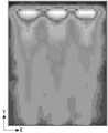
도 2는 도 1에 도시된 도광판의 상면 상에 나타나는 휘도 분포를 나타내는 도면,FIG. 2 is a diagram illustrating a luminance distribution appearing on an upper surface of the light guide plate illustrated in FIG. 1;
도 3은 본 발명의 바람직한 제1 실시예에 따른 휴대 단말기용 백라이트 유닛을 나타내는 측면도,3 is a side view showing a backlight unit for a portable terminal according to a first embodiment of the present invention;
도 4는 도 3에 도시된 제1 및 제2 경사면의 기능을 설명하기 위한 도면,4 is a view for explaining the function of the first and second inclined surfaces shown in FIG.
도 5는 도 4에 도시된 도광판의 단부 모서리를 확대한 도면,5 is an enlarged view of an end edge of the light guide plate shown in FIG. 4;
도 6은 광원의 최대 방사각과 제1 및 제2 경사면의 경사각과의 관계를 나타내는 그래프,6 is a graph showing the relationship between the maximum radiation angle of the light source and the inclination angles of the first and second inclined surfaces;
도 7은 도 3에 도시된 도광판의 상면 상에 나타나는 휘도 분포를 나타내는 도면,7 is a view illustrating a luminance distribution appearing on an upper surface of the light guide plate illustrated in FIG. 3;
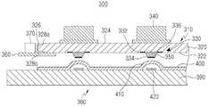
도 8은 본 발명의 바람직한 제2 실시 예에 따른 키 패드 어셈블리를 나타내는 단면도.8 is a cross-sectional view showing a keypad assembly according to a second embodiment of the present invention.
본 발명은 백라이트 유닛(backlight unit: BLU)에 관한 것으로서, 특히 핸드폰과 같은 휴대 단말기에 실장되는 도광판(light guide panel: LGP)을 이용한 백라이트 유닛에 관한 것이다.BACKGROUND OF THE INVENTION 1. Field of the Invention The present invention relates to a backlight unit (BLU), and more particularly to a backlight unit using a light guide panel (LGP) mounted in a portable terminal such as a mobile phone.
도 1은 종래의 휴대 단말기용 백라이트 유닛을 나타내는 측면도이다. 상기 백라이트 유닛(100)은 반사판(reflecting panel, 140)과, 복수의 광원(light source, 130)과, 도광판(110)과, 제1 및 제2 확산판(diffusing panel, 150,180)과, 제1 및 제2 프리즘 시트(prism sheet, 160,170)를 포함한다. 도시된 좌표에서, Z축은 상기 백라이트 유닛(100)의 조명 방향(다르게 말하자면, 상기 도광판(110)의 상면(114)의 법선)과 일치하고, Y축은 상기 각 광원(130)에서 출력된 광의 진행 방향과 일치하며, X축은 상기 Y축 및 Z축에 수직한 방향과 일치한다. Z축에 따른 상기 백라이트 유닛(100)의 상측에, 하부 및 상부 편광기(lower and upper polarizers)와, 상기 하부 및 상부 편광기의 사이에 개재되며 칼라 필터(color filter), 박막 트랜지스터(thin film transistor: TFT) 등을 구비한 액정을 포함하는 액정 패널(liquid crystal panel)(미도시)이 배치될 수 있다.1 is a side view showing a conventional backlight unit for a portable terminal. The
상기 도광판(110)은 서로 대향된 상면(114) 및 하면(112)과, 상기 상면(114) 및 하면(112) 사이에 위치하고 서로 대향된 제1 및 제2 측면(116,118)을 갖는다. 상기 각 광원(130)은 상기 도광판(110)의 제1 측면(116)과 대면하며, 상기 제1 측면(116)을 향해 광을 출력한다. 상기 도광판(110)은 제1 측면(116)을 통해 그 내부로 입력된 광을 상면(114) 및 하면(112) 사이의 내부 전반사(total internal reflection)를 통해 제2 측면(118)으로 도파시킨다. 상기 도광판(110)은 그 하면(112) 상에 형성된 복수의 광 추출 패턴들(light extracting pattern, 120)을 갖는다. 상기 각 광 추출 패턴(120)은 입사된 광을 난반사한다. 상기 각 광 추출 패턴(120)은 상기 도광판(110)과 외부 공기층의 경계면에서의 내부 전반사 조건을 파괴함으로써, 상기 각 광 추출 패턴(120)에서 난반사된 광이 상기 도광판(110)의 상면(114)을 투과하도록 한다.The
상기 반사판(140)은 그 상면이 상기 도광판(110)의 하면(112)과 대면하도록 배치되며, 상기 광 추출 패턴들(120)로 인해 상기 도광판(110)의 하면(112)을 투과한 광을 되반사시켜서, 다시 상기 도광판(110)의 내부로 입력되도록 한다.The
상기 제1 확산판(150)은 그 하면이 상기 도광판(110)의 상면(114)과 대면하도록 배치되며, 입력된 광을 산란(scattering) 및 투과시킨다.The
상기 제1 프리즘 시트(160)는 그 하면이 상기 제1 확산판(150)의 상면과 대면하도록 배치되며, 기판(162)과 상기 기판(162)의 상면으로부터 돌출되도록 형성되며 서로 평행하게 이격된 복수의 프리즘 산들(164)로 이루어진다. 이때, 각 프리즘 산(164)은 Y축을 따라(다르게 말하자면, 상기 도광판(110)의 제1 측면(116)의 법선을 따라) 연장된다. 상기 제1 프리즘 시트(160)는 입력된 광을 그 횡단면(다르게 말하자면, X-Z 평면) 상에서 집광 및 투과시킨다.The
상기 제2 프리즘 시트는(170) 그 하면이 상기 제1 프리즘 시트(160)의 상면과 대면하도록 배치되며, 기판(172)과 상기 기판(172)의 상면으로부터 돌출되도록 형성되며 서로 평행하게 이격된 복수의 프리즘 산들(174)로 이루어진다. 이때, 각 프리즘 산(174)은 X축을 따라(다르게 말하자면, 상기 도광판(110)의 제1 측면(116)의 법선과 수직하게) 연장된다. 상기 제2 프리즘 시트(170)는 입력된 광을 그 횡단면(다르게 말하자면, Y-Z 평면) 상에서 집광 및 투과시킨다.The
상기 제2 확산판(180)은 그 하면이 상기 제2 프리즘 시트(170)의 상면과 대면하도록 배치되며, 입력된 광을 산란 및 투과시킨다.The
상기 각 광원으로는 색재현성이 양호한 발광 다이오드(light emitting diode: LED)를 사용할 수 있으며, 상기 광원들의 수는 3 개이다.Each light source may be a light emitting diode (LED) having good color reproducibility, and the number of the light sources is three.
도 2는 상기 도광판(110)의 상면(114) 상에 나타나는 휘도 분포를 나타내는 도면이다. 상기 휘도 분포에서, 상대적으로 밝은 부분이 휘도가 높고, 상대적으로 어두운 부분이 휘도가 낮다. 도시된 바와 같이, 제1 측면(116)을 포함하는 상기 도광판(110)의 단부에서 최대 휘도를 갖는 복수의 핫스팟(hot spot)이 발생함을 알 수 있고, 상기 핫스팟들의 수는 상기 광원들(130)의 수와 일치한다. 이러한 핫스팟은 상기 도광판(110)의 상면(114) 및 하면(112)에 임계각(critical angle)보다 작지만 이에 근접한 각도로 입사하는 광이 상기 광 추출 패턴들(120)에 입사함으로써 유발된다. 이러한 핫스팟은 전체적인 조명 휘도 및 휘도 균일도를 저하시킨다.2 is a diagram illustrating a luminance distribution appearing on the
상기 도광판(110)의 상면(114) 및 하면(112)에 입사하는 광의 최소 입사각은 상기 각 광원(130)의 최대 방사각(maximum radiation angle)(다르게 말하자면, MFFA(maximum far-filed angle))에 의해 결정된다. 따라서, 최대 방사각이 작은 발광 다이오드를 사용하는 것이 핫스팟 문제를 해소하는데 있어서 유리하다. 이때, 상기 광원으로부터 출력되는 광 중 유효 방사각(effective radiaiton angle) 내의 광만을 사용할 수도 있으므로, 여기에서 말하는 최대 방사각(maximum radiation angle)이란 이러한 유효 최대 방사각을 포함한다.The minimum incident angle of light incident on the
통상적인 발광 다이오드는 반치폭(full width at half maximum)이 60°에 이를 정도로 최대 방사각이 매우 크다. 이때, 방사각은 상기 발광 다이오드의 출력면의 법선을 기준으로 측정된다. 또한, 발광 다이오드는 최대 방사각이 작을수록 가격이 급격하게 높아지므로, 이러한 고가의 발광 다이오드를 휴대 단말기용 백라이트 유닛에 적용하기 어렵다는 문제점이 있다.Conventional light emitting diodes have a very large maximum radiation angle such that the full width at half maximum reaches 60 °. In this case, the radiation angle is measured based on the normal of the output surface of the light emitting diode. In addition, since the price of the light emitting diode increases rapidly as the maximum emission angle is small, it is difficult to apply such an expensive light emitting diode to a backlight unit for a portable terminal.
본 발명은 상술한 종래의 문제점을 해결하기 위하여 도출된 것으로서, 본 발명의 목적은 사용하는 광원의 큰 방사각에 따른 핫스팟 현상을 감소시킴으로써 종래에 비해 전체적인 조명 휘도 및 휘도 균일도를 향상시킬 수 있는 휴대 단말기용 백라이트 유닛을 제공함에 있다.The present invention is derived to solve the above-mentioned conventional problems, the object of the present invention is to reduce the hot spot phenomenon according to the large emission angle of the light source to be used, which can improve the overall illumination brightness and brightness uniformity compared to the conventional A backlight unit for a terminal is provided.
상기한 문제점을 해결하기 위하여, 본 발명에 따른 휴대 단말기용 백라이트 유닛은, 서로 대향된 상면 및 하면과, 상기 상면 및 하면 사이에 위치하며 서로 대향된 제1 및 제2 측면을 구비하며, 상기 상면 및 하면 사이의 내부 반사를 통해 그 내부로 광이 진행하는 도광판과; 상기 제1 측면과 대면하도록 배치되며, 상기 도광판의 내부로 광을 입력하는 적어도 하나의 광원과; 상기 도광판의 내부로 진행하는 광을 상기 도광판의 외부로 출력하기 위해 상기 도광판 상에 형성된 적어도 하나의 광 추출 패턴을 포함하고, 상기 제1 측면을 포함하는 상기 도광판의 단부는 상기 상면 및 하면 중 적어도 하나로부터 상기 제1 측면을 향해 내향 경사진 적어도 하나의 경사면을 더 구비한다.In order to solve the above problems, the backlight unit for a portable terminal according to the present invention includes upper and lower surfaces facing each other, and first and second side surfaces disposed between the upper and lower surfaces and opposed to each other. And a light guide plate through which the light propagates through the internal reflection between the lower surface; At least one light source disposed to face the first side surface and configured to input light into the light guide plate; At least one light extraction pattern formed on the light guide plate to output light traveling to the inside of the light guide plate to the outside of the light guide plate, and an end portion of the light guide plate including the first side surface has at least one of the upper and lower surfaces; And at least one inclined surface that slopes inwardly from one toward the first side surface.
이하에서는 첨부 도면들을 참조하여 본 발명의 실시 예를 상세히 설명하기로 한다. 본 발명을 설명함에 있어서, 관련된 공지 기능이나 구성에 대한 구체적인 설명은 본 발명의 요지를 모호하지 않게 하기 위하여 생략한다.Hereinafter, with reference to the accompanying drawings will be described an embodiment of the present invention; In describing the present invention, detailed descriptions of related well-known functions and configurations are omitted in order not to obscure the subject matter of the present invention.
도 3은 본 발명의 바람직한 제1 실시예에 따른 휴대 단말기용 백라이트 유닛을 나타내는 측면도이다. 상기 백라이트 유닛(200)은 반사판(240)과, 복수의 광원(230)과, 도광판(210)과, 제1 및 제2 확산판(250,280)과, 제1 및 제2 프리즘 시트(260,270)를 포함한다. 도시된 좌표에서, Z축은 상기 백라이트 유닛(200)의 조명 방향(다르게 말하자면, 상기 도광판(210)의 상면(214)의 법선)과 일치하고, Y축은 상기 각 광원(230)에서 출력된 광의 진행 방향과 일치하며, X축은 상기 Y축 및 Z축에 수직한 방향과 일치한다. Z축에 따른 상기 백라이트 유닛(200)의 상측에, 하부 및 상부 편광기와, 상기 하부 및 상부 편광기의 사이에 개재되며 칼라 필터, 박막 트랜지스터 등을 구비한 액정을 포함하는 액정 패널(미도시)이 배치될 수 있다.3 is a side view illustrating a backlight unit for a portable terminal according to a first embodiment of the present invention. The
상기 도광판(210)은 전체적으로 직육면체의 형태를 가지며, 서로 대향된 상면(214) 및 하면(212)과, 상기 상면(214) 및 하면(212) 사이에 위치하고 서로 대향된 제1 및 제2 측면(216,218)을 갖는다. 상기 각 광원(230)은 상기 도광판(210)의 제1 측면(216)과 대면하며, 상기 제1 측면(216)을 향해 광을 출력한다. 상기 도광 판(210)은 제1 측면(216)을 통해 그 내부로 입력된 광을 상면(214) 및 하면(212) 사이의 내부 전반사를 통해 제2 측면(218)으로 도파시킨다. 상기 도광판(210)은 폴리카보네이트(polycarbonate) 또는 아크릴계 수지(acryl-based resin)를 사출 성형하여 제작될 수 있다.The
상기 도광판(210)은 하면(212) 상에 형성된 복수의 광 추출 패턴들(225)을 갖는다. 상기 각 광 추출 패턴(225)은 입사된 광을 난반사한다. 즉, 상기 각 광 추출 패턴(225)은 상기 도광판(210)과 외부 공기층의 경계면에서의 내부 전반사 조건을 파괴함으로써, 상기 각 광 추출 패턴(225)에서 난반사된 광이 상기 도광판(210)의 상면(214)을 투과하도록 한다. 상기 각 광 추출 패턴(225)은 인쇄(printing), 사진식각(photolithography), 레이징(lasing), 스템핑(stamping) 등에 의해 형성되는 스크래치(scratch), 요철, 프리즘 패턴(prism pattern) 등일 수 있다. 선택적으로, 상기 각 광 추출 패턴(225)은 주기적인 굴절률 변화를 갖는 브래그 격자(Bragg grating) 등의 형태로도 제공될 수 있으며, 이러한 굴절률 변화는 폴링(polling), 자외선 조사 등을 통해 구현될 수 있다. 또한, 선택적으로, 상기 광 추출 패턴들(225)은 상기 도광판(210)의 상면(214) 상에 형성될 수도 있다. 또한, 본 실시예에서, 균일한 조명을 위해 상기 광 추출 패턴(225)이 입사된 광을 난반사시키는 것으로 한정하고 있으나, 이와 다르게 거울 반사를 일으키는 V-홈(V-groove), 내부 전반사 조건을 파괴하는 굴절률(예를 들어, 상기 광도파로의 굴절률과 유사한 굴절률)을 갖는 코팅층(coating layer) 등의 형태로도 제공될 수 있다.The
도 3 및 4를 참고하면, 상기 제1 측면(216)을 포함하는 상기 도광판(210)의 단부는, 상면(214)으로부터 상기 제1 측면(216)을 향해 θS의 각도로 내향 경사진 제1 경사면(220)과, 상기 하면(212)으로부터 상기 제1 측면(216)을 향해 θS의 각도로 내향 경사진 제2 경사면(222)을 포함한다. 다르게 말하자면, 상기 각 경사면은 상기 제1 측면으로부터 이격된 위치에서 상기 상면으로부터 상기 제1 측면까지 내향 경사져 있다.3 and 4, an end portion of the
도 4는 상기 제1 및 제2 경사면(220,222)의 기능을 설명하기 위한 도면이다. 도 4에서, 도광판(210)의 상면(214)을 가상으로 절곡없이 연장함으로써 얻어지는 연장면은 점선으로 표시되어 있고, 상기 제1 경사면(220)에 의해 반사된 광은 가는 실선으로 표시되어 있으며, 상기 연장면에 의해 반사된 가상의 광은 가는 점선으로 표시되어 있다. 도 4에서, t는 상기 도광판(210)의 두께를 나타내고, l은 상기 도광판(210)의 제1 측면(216)으로부터 상기 광 추출 패턴들(225)의 시작 위치까지의 거리를 나타낸다. 상기 연장면에 의해 반사된 가상의 광은 상기 도광판(210)의 제1 측면(216)과 상기 광 추출 패턴들(225)의 사이에 위치하는 하면(212) 부분에 입사된다. 이는 상기 도광판(210)의 상면(214)의 법선을 기준으로 할 때, 상기 가상의 광이 갖는 반사각이 임계각에 근접할 정도로 작기 때문에 발생하는 현상이다. 부언하여, 한 면의 법선을 기준으로 할 때, 상기 면에 입사하는 광의 입사각과 반사각은 동일하다. 상기 제1 경사면(220)은 상기 도광판(210)의 상면(214)을 기준으로 상기 제1 측면(216)을 향해 내향 경사져 있으므로, 상기 제1 경사면(220)은 상기 연장면과 비교하여 입사된 광의 입사각을 θS만큼 증가시키는 기능을 한다. 예를 들 어, 상기 도광판(210)의 상면(214)의 법선을 기준으로 할 때, 상기 연장면에 입사하는 광의 입사각이 θ1이라고 가정하면, 상기 제1 경사면(220)에 입사하는 광의 입사각은 (θ1+θS)이 된다. 마찬가지로, 상기 제1 경사면(220)으로부터 반사되는 광의 반사각은 (θ1+θS)이 된다. 전술한 바와 마찬가지로, 상기 제2 경사면(222)은 상기 도광판(210)의 하면(212)을 절곡없이 연장함으로써 얻어지는 연장면과 비교하여 입사된 광의 입사각을 θS만큼 증가시키는 기능을 한다.4 is a view for explaining the function of the first and second inclined surfaces (220, 222). In FIG. 4, the extended surface obtained by virtually bending the
도 5는, 상기 제1 측면(216)을 포함하는 상기 도광판(210)의 단부 모서리를 확대한 도면으로서, 상기 제1 및 제2 경사면(220,222)의 경사각을 설정하는 원리를 설명하기 위한 도면이다. 상기 각 광원(230)의 최대 방사각을 θ라고 하면, 상기 제1 경사면(220)에 의해 반사된 광을 상기 광 추출 패턴들(225)의 시작 위치보다 먼 위치에 도달시키기 위한 조건은 아래와 같은 <수학식 1>로 표시될 수 있다. 다만, 이는 최적의 조건을 제시하는 것일 뿐, 이러한 조건으로 본 발명이 제한되지 않음에 주의해야 한다. 부언하여, 아래의 <수학식 1>은 근사식으로서, 최대 방사각의 광이 상기 제1 경사면(220)에 입사하는 점을 기준으로 하여, 제1 측면(216)까지의 거리와, 연장면까지의 거리가 무시할 정도로 작다는 가정에 근거한 것이다.FIG. 5 is an enlarged view of an end edge of the

상기 <수학식 1>에서, θR은 상기 도광판(210)의 상면(214)의 법선을 기준으 로 할 때 상기 제1 경사면(220)에 의해 반사된 최대 방사각의 광이 갖는 반사각을 나타내고, θm은 상기 제1 측면(216)을 기준으로 한 최대 방사각의 광이 갖는 굴절각을 나타낸다.In Equation 1, θR represents a reflection angle of light having a maximum emission angle reflected by the first
위 <수학식 1>로부터 아래의 <수학식 2>가 도출된다.Equation 2 below is derived from Equation 1 above.

또한, 상기 도광판(210)의 굴절률을 n이라고 하면, 공기의 굴절률은 1이므로, 스넬의 법칙에 따라 θm은 아래의 <수학식 3>과 같이 도출된다.In addition, if the refractive index of the

상기 <수학식 2> 및 <수학식 3>으로부터, 아래의 <수학식 4>가 도출된다.From Equation 2 and Equation 3, Equation 4 below is derived.

도 6은 상기 각 광원(230)의 최대 방사각과 제1 및 제2 경사면(220,222)의 경사각과의 관계를 나타내는 그래프이다. 도시된 그래프는 상기 <수학식 4>에 근거한 것이며, t는 0.5㎜이고, l은 1.5㎜이며, n은 1.52인 것으로 가정한다. 따라서, 최대 방사각이 30°~60°범위인 광원을 사용한다면, 제1 및 제2 경사면의 경사각은 2.5°~10°범위를 갖는다. 상기 제1 경사면(220)은, 상기 도광판(210)의 상면(214) 으로부터 반사된 광이 상기 광 추출 패턴들(225)의 시작 위치 또는 이보다 먼 위치에 도달할 수 있도록, 상기 제1 측면(216)으로부터 상기 시작 위치에 도달하는 광의 반사 지점까지 연장되는 것이 바람직하다. 상기 제2 경사면(220)은 상기 제1 경사면(220)과 동일한 길이로 연장된다.6 is a graph illustrating a relationship between the maximum radiation angle of each of the
다시 도 3을 참조하면, 상기 반사판(240)은 그 상면이 상기 도광판(210)의 하면(212)과 대면하도록 상기 도광판(210)의 아래에 배치되며, 상기 도광판(210)의 하면(212)을 투과한 광을 되반사시켜서, 다시 상기 도광판(210)의 내부로 입력되도록 한다.Referring to FIG. 3 again, the
상기 제1 확산판(250)은 그 하면이 상기 도광판(210)의 상면(214)과 대면하도록 상기 도광판(210)의 위에 배치되며, 입력된 광을 산란 및 투과시킨다.The
상기 제1 프리즘 시트(260)는 그 하면이 상기 제1 확산판(250)의 상면과 대면하도록 상기 제1 확산판(250)의 위에 배치되며, 배치되며, 기판(262)과 상기 기판(262)의 상면으로부터 돌출되도록 형성되며 서로 평행하게 이격된 복수의 프리즘 산들(264)로 이루어진다. 이때, 각 프리즘 산(264)은 Y축을 따라(다르게 말하자면, 상기 도광판(210)의 제1 측면(216)의 법선을 따라) 연장된다. 상기 제1 프리즘 시트(260)는 입력된 광을 그 횡단면(다르게 말하자면, X-Z 평면) 상에서 집광 및 투과시킨다.The
상기 제2 프리즘 시트(270)는 그 하면이 상기 제1 프리즘 시트(260)의 상면과 대면하도록 상기 제1 프리즘 시트(260)의 위에 배치되며, 기판(272)과 상기 기판(272)의 상면으로부터 돌출되도록 형성되며 서로 평행하게 이격된 복수의 프리즘 산들(274)로 이루어진다. 이때, 각 프리즘 산(274)은 X축을 따라(다르게 말하자면, 상기 도광판(210)의 제1 측면(216)의 법선과 수직하게) 연장된다. 상기 제2 프리즘 시트(270)는 입력된 광을 그 횡단면(다르게 말하자면, Y-Z 평면) 상에서 집광 및 투과시킨다.The
상기 제2 확산판(280)은 그 하면이 상기 제2 프리즘 시트(270)의 상면과 대면하도록 상기 제2 프리즘 시트(270)의 위에 배치되며, 입력된 광을 산란 및 투과시킨다.The
상기 각 광원(230)으로는 색재현성이 양호한 발광 다이오드를 사용할 수 있으며, 상기 광원들(230)의 수는 2 개이다.Each of the
도 7은 상기 도광판(210)의 상면(214) 상에 나타나는 휘도 분포를 나타내는 도면이다. 상기 휘도 분포에서, 상대적으로 밝은 부분이 휘도가 높고, 상대적으로 어두운 부분이 휘도가 낮다. 도시된 바와 같이, 제1 측면(216)을 포함하는 상기 도광판(210)의 단부에서 최대 휘도를 갖는 핫스팟들이 발생함을 알 수 있고, 상기 핫스팟들의 수는 상기 광원들(230)의 수와 일치한다. 광원의 개수에 있어서 차이가 있기는 하지만, 도 2와 비교하면, 종래에 비하여 핫스팟의 크기 및 휘도가 크게 감소함을 알 수 있다.FIG. 7 is a diagram illustrating a luminance distribution appearing on the
전술한 바와 같이, 본 발명의 제1 실시예에 따른 백라이트 유닛(200)은 액정 표시 장치에 적용 가능하고, 또한 다양한 변형을 통해 다양한 용도로 사용될 수 있다.As described above, the
이하, 본 발명의 제2 실시예는 종래의 키 패드(keypad)에 대응되는 백라이트 유닛을 예시하며, 이미 상술하였으므로 경사면에 대한 상세한 설명은 생략한다.Hereinafter, the second embodiment of the present invention exemplifies a backlight unit corresponding to a conventional keypad, and since it has been described above, a detailed description of the inclined surface is omitted.
도 8은 본 발명의 바람직한 제2 실시 예에 따른 키 패드 어셈블리를 나타내는 단면도이다. 상기 키 패드 어셈블리(keypad assembly, 300)는 백라이트 유닛(310)과, 상기 백라이트 유닛(310)과 이격되게 배치된 스위치 기판(switch board, 380)을 포함한다.8 is a cross-sectional view showing a keypad assembly according to a second embodiment of the present invention. The
상기 백라이트 유닛(310)은 도광판(320)과, 복수의 키 버튼(key button, 340)과, 복수의 돌기(protrusion, 350)(또는 엑츄에이터(actuator))와, 복수의 광 추출 패턴(330)과, 복수의 광원(370)와, 제2 인쇄회로기판(360)을 포함한다.The
상기 도광판(320)은 전체적으로 직육면체의 형태를 가지며, 서로 대향된 상면(324) 및 하면(322)과, 상기 상면(324) 및 하면(322) 사이에 위치하고 서로 대향된 제1 측면(326) 및 제2 측면(미도시)을 갖는다. 상기 도광판(320)은 제1 측면(326)을 통해 그 내부로 입력된 광을 도파시킨다. 상기 입력된 광은 상기 도광판(320)의 제1 측면(326)으로부터 제2 측면으로 진행한다. 상기 도광판(320)의 내부로 입력된 광은 상기 도광판(320)과 그 외부의 공기층의 경계에서의 내부 전반사에 의해 상기 도광판(320) 내부로 진행한다. 상기 제1 측면(326)을 포함하는 상기 도광판(320)의 단부는, 상면(324)으로부터 상기 제1 측면(326)을 향해 기설정된 각도로 내향 경사진 제1 경사면(328a)과, 상기 하면(322)으로부터 상기 제1 측면(326)을 향해 기설정된 각도로 내향 경사진 제2 경사면(328b)을 포함한다.The
상기 도광판(320)은 탄성이 있어서, 상기 키 버튼(340)이 눌려진 후 다시 원위치로 돌아가도록 한다. 즉, 상기 도광판(320)은 자체 복원력이 있어서 변형 후 원형으로 복원되며, 상기 키 버튼(340)의 작동 후 상기 키 버튼(340)을 원위치로 복원시킨다.The
상기 도광판(320)은 양호한 클릭 감을 제공하며, 키 버튼들(340) 간의 간섭 현상을 억제하고, 반복적인 작동에도 영구 변형이 발생하지 않도록 낮은 경도, 높은 탄성 변형률, 높은 탄성 복원력 및 높은 광투과도를 갖는 고투명 고무 재질로 형성되는 것을 특징으로 하며, 바람직하게는 폴리우레탄(polyurethane), 실리콘(silicone) 등의 재질로 형성된다.The
상기 제2 인쇄회로기판(360)은 상기 도광판(320)의 하면(322)의 가장자리 부분에 부착되며, 상기 복수의 광원(370)는 상기 도광판(320)의 제1 측면(326)과 그 출력면이 대향하도록 상기 제2 인쇄회로기판(360)의 상면에 탑재된다. 상기 광원(370)으로부터 출사된 광은 상기 도광판(320)의 제1 측면을 통해 그 내부로 입력된다. 상기 제2 인쇄회로기판(360)으로는 통상의 연성 인쇄회로기판(flexible PCB: FPCB)을 사용할 수 있으며, 상기 각 광원(370)으로는 통상의 발광 다이오드를 사용할 수 있다.The second printed
상기 복수의 키 버튼(340)은 상기 도광판(320)의 상면(324)으로부터 돌출되며, 각각 그 상면에 문자, 숫자 등이 인쇄된다. 상기 키 버튼들(340)은 상기 도광판(320)과 동일한 또는 다른 재질로 일체(one-piece) 형성되거나, 폴리카보네이트 또는 아크릴계 수지 등의 재질로 형성된 후 상기 도광판(320)의 상면(324)에 부착될 수 있다. 상기 각 키 버튼(340)은 원 기둥, 타원 기둥 등의 임의의 형상을 가질 수 있다.The plurality of
상기 복수의 돌기(350)는 상기 도광판(320)의 하면(322)으로부터 돌출된다. 상기 돌기들(350)은 상기 도광판(320)과 동일한 또는 다른 재질로 일체 형성되거나, 별도로 형성된 후 상기 도광판(320)의 하면(322)에 부착될 수 있다. 상기 각 돌기(350)는 원뿔대, 사다리꼴 육면체 등의 임의의 형상을 가질 수 있다. 상기 각 돌기(350)는 해당 키 버튼(340)의 아래에 정렬된다(상기 키 패드 어셈블리(300)의 두께 방향 또는 제1 인쇄회로기판(390)의 상면에 수직인 방향으로).The plurality of
상기 백라이트 유닛(310)는 상기 도광판(320)의 하면(322) 상에 형성되며 각각 상기 도광판(320) 내로 진행하는 광의 일부를 해당 키 버튼(340) 측으로 반사하는 복수의 광 추출 패턴(330)(속이 검은색으로 채워진 삼각형으로 표시함)을 갖는다. 필요에 따라, 상기 광 추출 패턴(330)은 상기 도광판(320)의 상면(324) 상에 형성될 수도 있다. 상기 각 광 추출 패턴(330)은 해당 키 버튼(340)의 바로 밑에 위치하는 해당 돌기(350) 및 상기 돌기(350)의 둘레에 형성됨으로써 상기 키 버튼(340)의 균일한 조명을 가능하게 한다. 또한, 전체 백라이트 유닛(310)에 있어서, 상기 광원(370)과 상대적으로 가까운 곳에 위치한 광 추출 패턴의 밀도 또는 크기와 상대적으로 먼 곳에 위치한 광 추출 패턴의 밀도 또는 크기를 서로 다르게 함으로써, 상기 도광판(320)의 상측으로 출사되는 전체적인 광량 분포를 상기 발광 소자(370)과의 거리에 상관없이 균일하게 조절할 수 있다. 예를 들어, 상기 발광 소자(370)를 기준으로 하여, 상대적으로 가까운 위치의 출사 광량이 상대적으로 많은 경우에는 상대적으로 가까운 위치의 반사 패턴의 밀도를 저밀도로 하고, 상대적으로 먼 위치의 출사 광량이 상대적으로 적은 경우에는 상대적으로 먼 위치의 반사 패턴의 밀도를 고밀도로 함으로써, 전체적인 출사 광량의 분포, 즉 상기 키 버튼들(340)의 전체적인 조명 분포를 균일하게 밝게 할 수 있다.The
상기 각 광 추출 패턴(330)의 중앙 부분(334)은 해당 돌기(350)의 하면 상에 형성되고, 상기 광 추출 패턴(330)의 가장자리 부분(332)은 상기 돌기(350)의 주변에 형성된다. 도시된 바와 같이, 상기 도광판(320) 내로 전반사 진행하는 광은 상기 광 추출 패턴(330)에 입사되고, 상기 광 추출 패턴(330)에 의해 키 버튼(340) 측으로 난반사된 광의 대부분은 전반사 조건을 만족하지 못하므로(입사각이 임계각보다 작은 경우) 상기 키 버튼(340)을 투과하여 외부로 출사된다. 또한, 상기 광 추출 패턴(330)에 의해 난반사되지 않고 그대로 지나치게 되는 광과 상기 난반사된 광의 일부는 전반사 조건을 만족하면서 상기 도광판(320) 내로 계속 진행함으로써, 다른 키 버튼을 조명하는데 기여하게 된다. 즉, 상기 광 추출 패턴(330)은 난반사를 일으킴으로써, 입사된 광의 일부만을 상기 키 버튼(340)의 조명에 사용하고 상기 입사광의 나머지는 다른 키 버튼의 조명에 사용되도록 한다. 또한, 상기 광 추출 패턴(330)은 임의의 방향으로의 난반사를 통해 상기 키 버튼(340)의 균일한 조명을 구현한다. 바람직하게는, 상기 반사 패턴(230)은 스크래치(scratch), 인쇄 등에 의해 형성될 수 있다.The
또한, 상기 각 광 추출 패턴(330)의 중앙 부분(336)(속이 채워지지 않은 삼각형으로 표시)을 해당 돌기(340)의 하면이 아니라 상기 도광판(320)과 상기 돌기(340)의 사이에 형성할 수도 있다.In addition, a central portion 336 (marked by an unfilled triangle) of each
상기 스위치 기판(380)은 상기 백라이트 유닛(310)의 아래에 배치되며, 제1 인쇄회로기판(390)과, 돔 시트(dome sheet, 400)를 포함한다.The
상기 제1 인쇄회로기판(390)은 그 상면에 형성된 복수의 도전성 접촉 부재(420)를 구비하며, 상기 각 접촉 부재(420)는 해당 돔(410)과 함께 스위치(410,420)를 구성한다. 또한, 상기 각 스위치(410,420)는 해당 돌기(350)의 아래에 정렬된다.The first printed
상기 돔 시트(400)는 상기 제1 인쇄회로기판(390)의 상면에 부착되고, 반구 형상을 갖는 복수의 도전성 돔들(410)을 구비하며, 상기 각 돔(410)은 해당 접촉 부재(420)를 완전히 덮는다.The dome sheet 400 is attached to an upper surface of the first printed
사용자가 어느 한 키 버튼(340)을 누르면, 상기 키 버튼(340)의 아래에 위치하는 상기 백라이트 유닛(310)의 부분이 상기 스위치 기판(380) 측으로 변형됨에 따라, 상기 변형된 부분에 속하는 해당 돌기(350)가 해당 돔(410)을 누르게 된다. 상기 눌려진 돔(410)은 해당 접촉 부재(420)와 전기적 접촉(다르게 말하자면, 접점)을 이루게 된다.When a user presses any one
한편, 본 발명의 상세한 설명에서는 구체적인 실시예에 관해서 설명하였으나, 본 발명의 범위에서 벗어나지 않는 한도 내에서 여러 가지 변형이 가능함은 당해 분야에서 통상의 지식을 가진 자에게 있어서 자명하다 할 것이다.On the other hand, in the detailed description of the present invention has been described with respect to specific embodiments, it will be apparent to those skilled in the art that various modifications are possible without departing from the scope of the present invention.
예를 들어, 본 발명의 실시예들에 있어서, 도광판이 제1 및 제2 경사면을 구비하는 것으로 예시하였으나, 이들 중 어느 한 경사면만을 포함할 수 있음은 자명하다.For example, in the embodiments of the present invention, although the light guide plate is illustrated as having the first and second inclined surfaces, it is obvious that any one of them may include only the inclined surfaces.
또한, 본 발명의 제2 실시예에서, 광원과 상대적으로 가까운 곳에 위치한 광 추출 패턴의 밀도 또는 크기와 상대적으로 먼 곳에 위치한 광 추출 패턴의 밀도 또는 크기를 서로 다르게 하는 것을 예시하였고, 이는 제1 실시예의 경우에도 적용할 수 있다.Further, in the second embodiment of the present invention, it is illustrated that the density or size of the light extraction pattern located relatively far from the density or size of the light extraction pattern located relatively close to the light source is different from each other, which is the first embodiment. The same applies to the case of example.
상술한 바와 같이, 본 발명에 따른 휴대 단말기용 백라이트 유닛은, 그 단부에 경사면을 갖는 도광판을 구비함으로써, 광원의 큰 방사각에 따른 핫스팟 현상을 감소시키고, 이로 인해 종래에 비해 전체적인 조명 휘도 및 휘도 균일도를 향상시킬 수 있다는 이점이 있다.As described above, the backlight unit for a portable terminal according to the present invention includes a light guide plate having an inclined surface at an end thereof, thereby reducing a hot spot phenomenon according to a large emission angle of the light source, and thus, the overall illumination luminance and luminance compared with the conventional one. There is an advantage that the uniformity can be improved.
Claims (10)
Translated fromKoreanPriority Applications (2)
| Application Number | Priority Date | Filing Date | Title |
|---|---|---|---|
| KR1020060067496AKR100819253B1 (en) | 2006-07-19 | 2006-07-19 | Backlight Units for Mobile Terminals |
| US11/787,930US20080019150A1 (en) | 2006-07-19 | 2007-04-18 | Backlight unit for portable terminal |
Applications Claiming Priority (1)
| Application Number | Priority Date | Filing Date | Title |
|---|---|---|---|
| KR1020060067496AKR100819253B1 (en) | 2006-07-19 | 2006-07-19 | Backlight Units for Mobile Terminals |
Publications (2)
| Publication Number | Publication Date |
|---|---|
| KR20080008065A KR20080008065A (en) | 2008-01-23 |
| KR100819253B1true KR100819253B1 (en) | 2008-04-02 |
Family
ID=38971277
Family Applications (1)
| Application Number | Title | Priority Date | Filing Date |
|---|---|---|---|
| KR1020060067496AExpired - Fee RelatedKR100819253B1 (en) | 2006-07-19 | 2006-07-19 | Backlight Units for Mobile Terminals |
Country Status (2)
| Country | Link |
|---|---|
| US (1) | US20080019150A1 (en) |
| KR (1) | KR100819253B1 (en) |
Cited By (1)
| Publication number | Priority date | Publication date | Assignee | Title |
|---|---|---|---|---|
| KR20110057802A (en)* | 2009-11-25 | 2011-06-01 | 엘지디스플레이 주식회사 | Backlight unit, manufacturing method thereof and liquid crystal display device using same |
Families Citing this family (28)
| Publication number | Priority date | Publication date | Assignee | Title |
|---|---|---|---|---|
| JP4765837B2 (en)* | 2006-08-23 | 2011-09-07 | ソニー株式会社 | Backlight device and liquid crystal display device |
| CA2758525A1 (en)* | 2009-04-16 | 2010-10-21 | Koninklijke Philips Electronics N.V. | A light guide apparatus |
| US9581756B2 (en) | 2009-10-05 | 2017-02-28 | Lighting Science Group Corporation | Light guide for low profile luminaire |
| US9157581B2 (en) | 2009-10-05 | 2015-10-13 | Lighting Science Group Corporation | Low profile luminaire with light guide and associated systems and methods |
| US9201185B2 (en)* | 2011-02-04 | 2015-12-01 | Microsoft Technology Licensing, Llc | Directional backlighting for display panels |
| US9354748B2 (en) | 2012-02-13 | 2016-05-31 | Microsoft Technology Licensing, Llc | Optical stylus interaction |
| US9075566B2 (en) | 2012-03-02 | 2015-07-07 | Microsoft Technoogy Licensing, LLC | Flexible hinge spine |
| US9460029B2 (en) | 2012-03-02 | 2016-10-04 | Microsoft Technology Licensing, Llc | Pressure sensitive keys |
| US8873227B2 (en) | 2012-03-02 | 2014-10-28 | Microsoft Corporation | Flexible hinge support layer |
| US9870066B2 (en) | 2012-03-02 | 2018-01-16 | Microsoft Technology Licensing, Llc | Method of manufacturing an input device |
| US20130300590A1 (en) | 2012-05-14 | 2013-11-14 | Paul Henry Dietz | Audio Feedback |
| US8947353B2 (en) | 2012-06-12 | 2015-02-03 | Microsoft Corporation | Photosensor array gesture detection |
| US9256089B2 (en) | 2012-06-15 | 2016-02-09 | Microsoft Technology Licensing, Llc | Object-detecting backlight unit |
| US8964379B2 (en) | 2012-08-20 | 2015-02-24 | Microsoft Corporation | Switchable magnetic lock |
| CN103185294A (en)* | 2013-04-07 | 2013-07-03 | 京东方科技集团股份有限公司 | Light guide plate manufacturing method |
| KR102147938B1 (en)* | 2013-12-27 | 2020-08-25 | 엘지이노텍 주식회사 | Lighting device |
| KR101458992B1 (en)* | 2014-01-28 | 2014-11-07 | (주)인크룩스 | Led illumination device applying light guiding plate |
| TW201533480A (en)* | 2014-02-25 | 2015-09-01 | Innolux Corp | Display device |
| CN104865745A (en)* | 2014-02-25 | 2015-08-26 | 群创光电股份有限公司 | Display device |
| US10120420B2 (en) | 2014-03-21 | 2018-11-06 | Microsoft Technology Licensing, Llc | Lockable display and techniques enabling use of lockable displays |
| US10324733B2 (en) | 2014-07-30 | 2019-06-18 | Microsoft Technology Licensing, Llc | Shutdown notifications |
| CN104749686A (en)* | 2015-04-02 | 2015-07-01 | 苏州胜利精密制造科技股份有限公司 | Composite light guide plate and liquid crystal display module comprising same |
| KR101728678B1 (en)* | 2015-05-18 | 2017-05-02 | 주식회사 엘엠에스 | Reflective Polarizing Module Having Particle and Back Light Unit Having the Same |
| JP2019514167A (en)* | 2016-04-08 | 2019-05-30 | コーニング インコーポレイテッド | Backlight unit including thin light guide plate and light coupling part |
| CN107132694B (en)* | 2017-06-14 | 2020-06-23 | 上海天马微电子有限公司 | Backlight module and display device |
| CN107561630B (en)* | 2017-09-15 | 2020-07-24 | 海信视像科技股份有限公司 | Backlight module and display device |
| TWI837121B (en)* | 2018-03-22 | 2024-04-01 | 日商日東電工股份有限公司 | Optical device |
| CN110673244B (en)* | 2019-09-27 | 2021-02-02 | 南京贝迪新材料科技股份有限公司 | Quantum dot composite brightness enhancement film and preparation method thereof |
Citations (3)
| Publication number | Priority date | Publication date | Assignee | Title |
|---|---|---|---|---|
| JPH06324217A (en)* | 1993-04-19 | 1994-11-25 | Brightview Technol Inc | Backlighting assembly having multiple-reflection lighting system and using micro-prism |
| KR20040020017A (en)* | 2002-08-30 | 2004-03-06 | 후지쯔 디스플레이 테크놀로지스 코포레이션 | Lighting unit and display device |
| JP2004146132A (en)* | 2002-10-22 | 2004-05-20 | Citizen Electronics Co Ltd | Flat light source |
Family Cites Families (1)
| Publication number | Priority date | Publication date | Assignee | Title |
|---|---|---|---|---|
| US6926418B2 (en)* | 2002-04-24 | 2005-08-09 | Nokia Corporation | Integrated light-guide and dome-sheet for keyboard illumination |
- 2006
- 2006-07-19KRKR1020060067496Apatent/KR100819253B1/ennot_activeExpired - Fee Related
- 2007
- 2007-04-18USUS11/787,930patent/US20080019150A1/ennot_activeAbandoned
Patent Citations (3)
| Publication number | Priority date | Publication date | Assignee | Title |
|---|---|---|---|---|
| JPH06324217A (en)* | 1993-04-19 | 1994-11-25 | Brightview Technol Inc | Backlighting assembly having multiple-reflection lighting system and using micro-prism |
| KR20040020017A (en)* | 2002-08-30 | 2004-03-06 | 후지쯔 디스플레이 테크놀로지스 코포레이션 | Lighting unit and display device |
| JP2004146132A (en)* | 2002-10-22 | 2004-05-20 | Citizen Electronics Co Ltd | Flat light source |
Cited By (2)
| Publication number | Priority date | Publication date | Assignee | Title |
|---|---|---|---|---|
| KR20110057802A (en)* | 2009-11-25 | 2011-06-01 | 엘지디스플레이 주식회사 | Backlight unit, manufacturing method thereof and liquid crystal display device using same |
| KR101725538B1 (en)* | 2009-11-25 | 2017-04-11 | 엘지디스플레이 주식회사 | Back Light Unit, Method for Manufacturing Thereof, and Liquid Crystal Display Using That Back Light Unit |
Also Published As
| Publication number | Publication date |
|---|---|
| KR20080008065A (en) | 2008-01-23 |
| US20080019150A1 (en) | 2008-01-24 |
Similar Documents
| Publication | Publication Date | Title |
|---|---|---|
| KR100819253B1 (en) | Backlight Units for Mobile Terminals | |
| KR100692742B1 (en) | Keypad and Keypad Assembly with Light Guide Layer | |
| EP1970928B1 (en) | Waveguide member and keypad assembly using the same | |
| RU2458382C2 (en) | Keyboard and keyboard unit | |
| US7947915B2 (en) | Keypad assembly | |
| US7186935B2 (en) | Keypad assembly for a portable terminal | |
| EP0881426A1 (en) | Surface light source and liquid crystal display, portable telephone and information terminal employing the surface light source | |
| KR100606081B1 (en) | Light Guide Plate, Key Pad, and Key Pad Assembly | |
| JPH10199316A (en) | Surface light source device | |
| RU2339074C2 (en) | Keyboard and keyboard unit | |
| KR100797645B1 (en) | Keypad lighting devices | |
| KR100689395B1 (en) | Key pad assembly | |
| KR100770827B1 (en) | Key pad and keypad assembly | |
| US7083316B2 (en) | Light guide plate with intervening layer and backlight system using same | |
| KR100744324B1 (en) | Key pad and keypad assembly | |
| KR100770850B1 (en) | Keypad and Keypad Assembly Using the Keypad | |
| KR20070009495A (en) | Key pad and keypad assembly | |
| JP2005116267A (en) | Surface light source device | |
| KR101023272B1 (en) | Keypad and keypad assembly | |
| KR100724897B1 (en) | Key pad assembly | |
| KR101407292B1 (en) | Backlight unit | |
| TW201205129A (en) | Light guide subassembly | |
| KR20070036115A (en) | Key pad and keypad assembly |
Legal Events
| Date | Code | Title | Description |
|---|---|---|---|
| A201 | Request for examination | ||
| PA0109 | Patent application | St.27 status event code:A-0-1-A10-A12-nap-PA0109 | |
| PA0201 | Request for examination | St.27 status event code:A-1-2-D10-D11-exm-PA0201 | |
| D13-X000 | Search requested | St.27 status event code:A-1-2-D10-D13-srh-X000 | |
| D14-X000 | Search report completed | St.27 status event code:A-1-2-D10-D14-srh-X000 | |
| E902 | Notification of reason for refusal | ||
| PE0902 | Notice of grounds for rejection | St.27 status event code:A-1-2-D10-D21-exm-PE0902 | |
| E13-X000 | Pre-grant limitation requested | St.27 status event code:A-2-3-E10-E13-lim-X000 | |
| P11-X000 | Amendment of application requested | St.27 status event code:A-2-2-P10-P11-nap-X000 | |
| P13-X000 | Application amended | St.27 status event code:A-2-2-P10-P13-nap-X000 | |
| PG1501 | Laying open of application | St.27 status event code:A-1-1-Q10-Q12-nap-PG1501 | |
| E701 | Decision to grant or registration of patent right | ||
| PE0701 | Decision of registration | St.27 status event code:A-1-2-D10-D22-exm-PE0701 | |
| GRNT | Written decision to grant | ||
| PR0701 | Registration of establishment | St.27 status event code:A-2-4-F10-F11-exm-PR0701 | |
| PR1002 | Payment of registration fee | St.27 status event code:A-2-2-U10-U11-oth-PR1002 Fee payment year number:1 | |
| PG1601 | Publication of registration | St.27 status event code:A-4-4-Q10-Q13-nap-PG1601 | |
| PR1001 | Payment of annual fee | St.27 status event code:A-4-4-U10-U11-oth-PR1001 Fee payment year number:4 | |
| PR1001 | Payment of annual fee | St.27 status event code:A-4-4-U10-U11-oth-PR1001 Fee payment year number:5 | |
| R18-X000 | Changes to party contact information recorded | St.27 status event code:A-5-5-R10-R18-oth-X000 | |
| FPAY | Annual fee payment | Payment date:20130227 Year of fee payment:6 | |
| PR1001 | Payment of annual fee | St.27 status event code:A-4-4-U10-U11-oth-PR1001 Fee payment year number:6 | |
| FPAY | Annual fee payment | Payment date:20140227 Year of fee payment:7 | |
| PR1001 | Payment of annual fee | St.27 status event code:A-4-4-U10-U11-oth-PR1001 Fee payment year number:7 | |
| FPAY | Annual fee payment | Payment date:20150226 Year of fee payment:8 | |
| PR1001 | Payment of annual fee | St.27 status event code:A-4-4-U10-U11-oth-PR1001 Fee payment year number:8 | |
| FPAY | Annual fee payment | Payment date:20160226 Year of fee payment:9 | |
| PR1001 | Payment of annual fee | St.27 status event code:A-4-4-U10-U11-oth-PR1001 Fee payment year number:9 | |
| FPAY | Annual fee payment | Payment date:20170224 Year of fee payment:10 | |
| PR1001 | Payment of annual fee | St.27 status event code:A-4-4-U10-U11-oth-PR1001 Fee payment year number:10 | |
| LAPS | Lapse due to unpaid annual fee | ||
| PC1903 | Unpaid annual fee | St.27 status event code:A-4-4-U10-U13-oth-PC1903 Not in force date:20180328 Payment event data comment text:Termination Category : DEFAULT_OF_REGISTRATION_FEE | |
| PC1903 | Unpaid annual fee | St.27 status event code:N-4-6-H10-H13-oth-PC1903 Ip right cessation event data comment text:Termination Category : DEFAULT_OF_REGISTRATION_FEE Not in force date:20180328 |