KR100818817B1 - A light control element and a display incorporating the same - Google Patents
A light control element and a display incorporating the sameDownload PDFInfo
- Publication number
- KR100818817B1 KR100818817B1KR1020040068680AKR20040068680AKR100818817B1KR 100818817 B1KR100818817 B1KR 100818817B1KR 1020040068680 AKR1020040068680 AKR 1020040068680AKR 20040068680 AKR20040068680 AKR 20040068680AKR 100818817 B1KR100818817 B1KR 100818817B1
- Authority
- KR
- South Korea
- Prior art keywords
- light
- control element
- light control
- display
- polarization
- Prior art date
- Legal status (The legal status is an assumption and is not a legal conclusion. Google has not performed a legal analysis and makes no representation as to the accuracy of the status listed.)
- Expired - Fee Related
Links
Images


Classifications
- G—PHYSICS
- G02—OPTICS
- G02F—OPTICAL DEVICES OR ARRANGEMENTS FOR THE CONTROL OF LIGHT BY MODIFICATION OF THE OPTICAL PROPERTIES OF THE MEDIA OF THE ELEMENTS INVOLVED THEREIN; NON-LINEAR OPTICS; FREQUENCY-CHANGING OF LIGHT; OPTICAL LOGIC ELEMENTS; OPTICAL ANALOGUE/DIGITAL CONVERTERS
- G02F1/00—Devices or arrangements for the control of the intensity, colour, phase, polarisation or direction of light arriving from an independent light source, e.g. switching, gating or modulating; Non-linear optics
- G02F1/01—Devices or arrangements for the control of the intensity, colour, phase, polarisation or direction of light arriving from an independent light source, e.g. switching, gating or modulating; Non-linear optics for the control of the intensity, phase, polarisation or colour
- G02F1/13—Devices or arrangements for the control of the intensity, colour, phase, polarisation or direction of light arriving from an independent light source, e.g. switching, gating or modulating; Non-linear optics for the control of the intensity, phase, polarisation or colour based on liquid crystals, e.g. single liquid crystal display cells
- G02F1/1323—Arrangements for providing a switchable viewing angle
- G—PHYSICS
- G02—OPTICS
- G02F—OPTICAL DEVICES OR ARRANGEMENTS FOR THE CONTROL OF LIGHT BY MODIFICATION OF THE OPTICAL PROPERTIES OF THE MEDIA OF THE ELEMENTS INVOLVED THEREIN; NON-LINEAR OPTICS; FREQUENCY-CHANGING OF LIGHT; OPTICAL LOGIC ELEMENTS; OPTICAL ANALOGUE/DIGITAL CONVERTERS
- G02F1/00—Devices or arrangements for the control of the intensity, colour, phase, polarisation or direction of light arriving from an independent light source, e.g. switching, gating or modulating; Non-linear optics
- G02F1/01—Devices or arrangements for the control of the intensity, colour, phase, polarisation or direction of light arriving from an independent light source, e.g. switching, gating or modulating; Non-linear optics for the control of the intensity, phase, polarisation or colour
- G02F1/13—Devices or arrangements for the control of the intensity, colour, phase, polarisation or direction of light arriving from an independent light source, e.g. switching, gating or modulating; Non-linear optics for the control of the intensity, phase, polarisation or colour based on liquid crystals, e.g. single liquid crystal display cells
- G02F1/133—Constructional arrangements; Operation of liquid crystal cells; Circuit arrangements
- G02F1/1333—Constructional arrangements; Manufacturing methods
- G02F1/1335—Structural association of cells with optical devices, e.g. polarisers or reflectors
- G02F1/133528—Polarisers
- H—ELECTRICITY
- H04—ELECTRIC COMMUNICATION TECHNIQUE
- H04N—PICTORIAL COMMUNICATION, e.g. TELEVISION
- H04N13/00—Stereoscopic video systems; Multi-view video systems; Details thereof
- H04N13/30—Image reproducers
- H04N13/302—Image reproducers for viewing without the aid of special glasses, i.e. using autostereoscopic displays
- H04N13/31—Image reproducers for viewing without the aid of special glasses, i.e. using autostereoscopic displays using parallax barriers
- H—ELECTRICITY
- H04—ELECTRIC COMMUNICATION TECHNIQUE
- H04N—PICTORIAL COMMUNICATION, e.g. TELEVISION
- H04N13/00—Stereoscopic video systems; Multi-view video systems; Details thereof
- H04N13/30—Image reproducers
- H04N13/356—Image reproducers having separate monoscopic and stereoscopic modes
- H04N13/359—Switching between monoscopic and stereoscopic modes
- G—PHYSICS
- G02—OPTICS
- G02F—OPTICAL DEVICES OR ARRANGEMENTS FOR THE CONTROL OF LIGHT BY MODIFICATION OF THE OPTICAL PROPERTIES OF THE MEDIA OF THE ELEMENTS INVOLVED THEREIN; NON-LINEAR OPTICS; FREQUENCY-CHANGING OF LIGHT; OPTICAL LOGIC ELEMENTS; OPTICAL ANALOGUE/DIGITAL CONVERTERS
- G02F1/00—Devices or arrangements for the control of the intensity, colour, phase, polarisation or direction of light arriving from an independent light source, e.g. switching, gating or modulating; Non-linear optics
- G02F1/01—Devices or arrangements for the control of the intensity, colour, phase, polarisation or direction of light arriving from an independent light source, e.g. switching, gating or modulating; Non-linear optics for the control of the intensity, phase, polarisation or colour
- G02F1/13—Devices or arrangements for the control of the intensity, colour, phase, polarisation or direction of light arriving from an independent light source, e.g. switching, gating or modulating; Non-linear optics for the control of the intensity, phase, polarisation or colour based on liquid crystals, e.g. single liquid crystal display cells
- G02F1/133—Constructional arrangements; Operation of liquid crystal cells; Circuit arrangements
- G02F1/1333—Constructional arrangements; Manufacturing methods
- G02F1/1335—Structural association of cells with optical devices, e.g. polarisers or reflectors
- G02F1/133528—Polarisers
- G02F1/133538—Polarisers with spatial distribution of the polarisation direction
- G—PHYSICS
- G02—OPTICS
- G02F—OPTICAL DEVICES OR ARRANGEMENTS FOR THE CONTROL OF LIGHT BY MODIFICATION OF THE OPTICAL PROPERTIES OF THE MEDIA OF THE ELEMENTS INVOLVED THEREIN; NON-LINEAR OPTICS; FREQUENCY-CHANGING OF LIGHT; OPTICAL LOGIC ELEMENTS; OPTICAL ANALOGUE/DIGITAL CONVERTERS
- G02F1/00—Devices or arrangements for the control of the intensity, colour, phase, polarisation or direction of light arriving from an independent light source, e.g. switching, gating or modulating; Non-linear optics
- G02F1/01—Devices or arrangements for the control of the intensity, colour, phase, polarisation or direction of light arriving from an independent light source, e.g. switching, gating or modulating; Non-linear optics for the control of the intensity, phase, polarisation or colour
- G02F1/13—Devices or arrangements for the control of the intensity, colour, phase, polarisation or direction of light arriving from an independent light source, e.g. switching, gating or modulating; Non-linear optics for the control of the intensity, phase, polarisation or colour based on liquid crystals, e.g. single liquid crystal display cells
- G02F1/133—Constructional arrangements; Operation of liquid crystal cells; Circuit arrangements
- G02F1/1333—Constructional arrangements; Manufacturing methods
- G02F1/1335—Structural association of cells with optical devices, e.g. polarisers or reflectors
- G02F1/13363—Birefringent elements, e.g. for optical compensation
- G02F1/133638—Waveplates, i.e. plates with a retardation value of lambda/n
- G—PHYSICS
- G02—OPTICS
- G02F—OPTICAL DEVICES OR ARRANGEMENTS FOR THE CONTROL OF LIGHT BY MODIFICATION OF THE OPTICAL PROPERTIES OF THE MEDIA OF THE ELEMENTS INVOLVED THEREIN; NON-LINEAR OPTICS; FREQUENCY-CHANGING OF LIGHT; OPTICAL LOGIC ELEMENTS; OPTICAL ANALOGUE/DIGITAL CONVERTERS
- G02F1/00—Devices or arrangements for the control of the intensity, colour, phase, polarisation or direction of light arriving from an independent light source, e.g. switching, gating or modulating; Non-linear optics
- G02F1/01—Devices or arrangements for the control of the intensity, colour, phase, polarisation or direction of light arriving from an independent light source, e.g. switching, gating or modulating; Non-linear optics for the control of the intensity, phase, polarisation or colour
- G02F1/13—Devices or arrangements for the control of the intensity, colour, phase, polarisation or direction of light arriving from an independent light source, e.g. switching, gating or modulating; Non-linear optics for the control of the intensity, phase, polarisation or colour based on liquid crystals, e.g. single liquid crystal display cells
- G02F1/133—Constructional arrangements; Operation of liquid crystal cells; Circuit arrangements
- G02F1/1333—Constructional arrangements; Manufacturing methods
- G02F1/1347—Arrangement of liquid crystal layers or cells in which the final condition of one light beam is achieved by the addition of the effects of two or more layers or cells
- G02F1/13471—Arrangement of liquid crystal layers or cells in which the final condition of one light beam is achieved by the addition of the effects of two or more layers or cells in which all the liquid crystal cells or layers remain transparent, e.g. FLC, ECB, DAP, HAN, TN, STN, SBE-LC cells
- G—PHYSICS
- G02—OPTICS
- G02F—OPTICAL DEVICES OR ARRANGEMENTS FOR THE CONTROL OF LIGHT BY MODIFICATION OF THE OPTICAL PROPERTIES OF THE MEDIA OF THE ELEMENTS INVOLVED THEREIN; NON-LINEAR OPTICS; FREQUENCY-CHANGING OF LIGHT; OPTICAL LOGIC ELEMENTS; OPTICAL ANALOGUE/DIGITAL CONVERTERS
- G02F1/00—Devices or arrangements for the control of the intensity, colour, phase, polarisation or direction of light arriving from an independent light source, e.g. switching, gating or modulating; Non-linear optics
- G02F1/01—Devices or arrangements for the control of the intensity, colour, phase, polarisation or direction of light arriving from an independent light source, e.g. switching, gating or modulating; Non-linear optics for the control of the intensity, phase, polarisation or colour
- G02F1/13—Devices or arrangements for the control of the intensity, colour, phase, polarisation or direction of light arriving from an independent light source, e.g. switching, gating or modulating; Non-linear optics for the control of the intensity, phase, polarisation or colour based on liquid crystals, e.g. single liquid crystal display cells
- G02F1/133—Constructional arrangements; Operation of liquid crystal cells; Circuit arrangements
- G02F1/1333—Constructional arrangements; Manufacturing methods
- G02F1/1347—Arrangement of liquid crystal layers or cells in which the final condition of one light beam is achieved by the addition of the effects of two or more layers or cells
- G02F1/13475—Arrangement of liquid crystal layers or cells in which the final condition of one light beam is achieved by the addition of the effects of two or more layers or cells in which at least one liquid crystal cell or layer is doped with a pleochroic dye, e.g. GH-LC cell
Landscapes
- Physics & Mathematics (AREA)
- Nonlinear Science (AREA)
- Crystallography & Structural Chemistry (AREA)
- Chemical & Material Sciences (AREA)
- General Physics & Mathematics (AREA)
- Optics & Photonics (AREA)
- Mathematical Physics (AREA)
- Signal Processing (AREA)
- Engineering & Computer Science (AREA)
- Multimedia (AREA)
- Liquid Crystal (AREA)
- Polarising Elements (AREA)
- Devices For Indicating Variable Information By Combining Individual Elements (AREA)
Abstract
Translated fromKoreanDescription
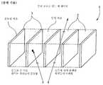
Translated fromKorean도 1은 루버(louvre) 구조를 갖는 공지된 광 제어막을 나타내는 도면.1 shows a known light control film having a louver structure.
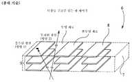
도 2는 다중 층 구조를 갖는 공지된 광 제어막을 나타내는 도면.2 shows a known light control film having a multilayer structure.
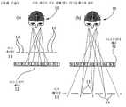
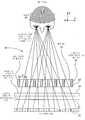
도 3은 시차-배리어(parallax-barrier) 자동 입체 디스플레이의 원리를 나타내는 도면.3 illustrates the principle of a parallax-barrier autostereoscopic display.
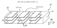
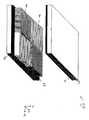
도 4는 본 발명의 편광-의존 광 제어 소자의 가능한 하나의 구조를 나타내는 도면.4 shows one possible structure of the polarization-dependent light control element of the present invention.
도 5는 본 발명의 편광-의존 광 제어 소자의 다른 구조를 나타내는 도면.Fig. 5 shows another structure of the polarization-dependent light control element of the present invention.
도 6은 개인 및 공용 관측 모드 사이에서 스위칭할 수 있는 본 발명의 디스플레이를 나타내는 도면.6 shows a display of the present invention that can switch between private and public viewing modes.
도 7은 도 6의 디스플레이의 동작을 나타내는 도면.7 illustrates the operation of the display of FIG. 6;
도 8의 (a)-(c)는 도 6의 디스플레이의 편광-의존 광 제어 소자의 제조 방법을 나타내는 도면.(A)-(c) is a figure which shows the manufacturing method of the polarization-dependent light control element of the display of FIG.
도 9의 (a)-(c)는 다른 편광-의존 광 제어 소자의 제조 방법을 나타내는 도면.(A)-(c) is a figure which shows the manufacturing method of another polarization-dependent light control element.
도 10의 (a)-(d)는 편광-의존 광 제어 소자의 구성을 위하여 투명 재료에 그 루브를 절단하는 2가지 방법을 나타내는 도면.10 (a)-(d) show two ways of cutting grooves in a transparent material for the construction of a polarization-dependent light control element.
도 11의 (a)-(b)는 편광-의존 광 제어 소자의 액정 재료에 대해 정렬층을 인가하기 위한 2가지 대안을 나타내는 도면.11 (a)-(b) show two alternatives for applying an alignment layer to the liquid crystal material of the polarization-dependent light control element.
도 12의 (a)-(b)는 흡수 재료막의 일부를 제거함으로써 편광-의존 광 제어 소자가 어떻게 구성될 수 있는 있는지를 나타내는 도면.12 (a)-(b) show how a polarization-dependent light control element can be constructed by removing part of an absorbing material film.
도 13의 (a)-(f)는 편광-의존 광 제어 소자의 구성을 위한 또다른 2개의 방법을 나타내는 도면.13 (a)-(f) show yet another two methods for the construction of the polarization-dependent light control element.
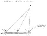
도 14는 개인 및 공용 관측 모드 사이를 스위칭할 수 있는 또다른 디스플레이를 나타내는 도면.14 shows another display capable of switching between private and public viewing modes.
도 15의 (a)-(b)는 도 14의 디스플레이의 동작을 나타내는 도면.15 (a)-(b) illustrate the operation of the display of FIG.
도 16은 4개의 관측 모드 사이에서 스위칭할 수 있는 본 발명의 디스플레이를 나타내는 도면.16 shows a display of the present invention that can switch between four viewing modes.
도 17의 (a)-(f)는 도 16의 디스플레이의 3개의 동작 모드를 나타내는 도면.17 (a)-(f) illustrate three operating modes of the display of FIG.
도 18은 자동 입체 개인 디스플레이 모드 또는 공용 디스플레이 모드로 동작할 수 있는 본 발명의 디스플레이를 나타내는 도면.18 illustrates a display of the present invention capable of operating in an autostereoscopic personal display mode or a common display mode.
도 19의 (a)는 도 18의 디스플레이의 광 제어 소자를 위한 다른 구조를 나타내는 도면.FIG. 19A shows another structure for the light control element of the display of FIG. 18; FIG.
도19의 (b)는 도 19의 (a)의 광 제어 소자의 제조를 나타내는 도면.FIG. 19B is a diagram showing manufacture of the light control element of FIG. 19A. FIG.
도 20은 2개의 관측자의 각각에 다른 개인 이미지를 나타낼 수 있는 본 발명의 디스플레이를 나타내는 도면.20 shows a display of the present invention that can present different personal images to each of two observers.
도 21은 장치 내부의 액정의 제어에 의해 스위칭가능한 편광-의존 광 제어 소자를 포함하는 본 발명의 디스플레이를 나타내는 도면.FIG. 21 shows a display of the present invention comprising a polarization-dependent light control element switchable by control of liquid crystal within the device.
도 22의 (a)-(b)는 도 21의 디스플레이의 가능한 하나의 구성의 동작 원리를 나타내는 도면.22 (a)-(b) illustrate the principle of operation of one possible configuration of the display of FIG. 21;
도 23의 (a)-(b)는 도 21의 디스플레이의 가능한 제2 구성의 동작 원리를 나타내는 도면.23 (a)-(b) illustrate the principle of operation of a possible second configuration of the display of FIG. 21;
도 24의 (a)-(b)는 도 21의 디스플레이의 가능한 제3 구성의 동작 원리를 나타내는 도면.Figures 24 (a)-(b) show the principle of operation of a possible third configuration of the display of figure 21;
도 25a, 25b는 본 발명의 또다른 광 제어 소자를 나타내는 도면.25A and 25B show another light control element of the present invention.
도 25c는 도 25b의 광 제어 소자를 포함하는 디스플레이의 측면도.FIG. 25C is a side view of a display including the light control element of FIG. 25B. FIG.
도 26은 본 발명의 또다른 광 제어 소자의 사시도.26 is a perspective view of another light control element of the present invention.
도 27의 (a)-(b)는 도 21의 광 제어 소자 및 본 발명의 또다른 실시예에 따른 광 제어 소자의 원리를 나타내는 도면.27 (a) to 27 (b) show the principle of the light control element of FIG. 21 and the light control element according to another embodiment of the present invention.
도 28의 (a), (b) 및 (c)는 본 발명의 또다른 광 제어 소자를 나타내는 도면.28A, 28B, and 28C show still another light control element of the present invention;
도 29 및 도 30은 본 발명의 광 제어 소자의 출력 각도 범위의 변동을 나타내는 도면.29 and 30 show variations in the output angle range of the light control element of the present invention.
도 31의 (a) 및 (b)는 본 발명의 또 다른 실시예에 따른 광 제어 소자의 단면도 및 평면도.31A and 31B are a cross-sectional view and a plan view of a light control device according to still another embodiment of the present invention.
도 32는 본 발명의 다른 실시예에 따른 광 제어 소자를 포함하는 디스플레이 의 단면도.32 is a cross-sectional view of a display including a light control element according to another embodiment of the present invention.
도 33은 본 발명의 광 제어 소자 상의 굴절율 미스매칭의 효과를 나타내는 도면.Fig. 33 shows the effect of refractive index mismatch on the light control element of the present invention.
〈도면의 주요 부분에 대한 부호의 설명〉<Explanation of symbols for main parts of drawing>
16 : 영역16: area
17 : 투명 재료17: transparent material
22 : 패널22: panel
23 : 편광기23: polarizer
24 : 파장 판24: wave plate
본 발명은 자신으로부터 출사(output)되는 광의 각도 범위를 제어할 수 있는 광 제어 소자에 관한 것이다. 또한, 본 발명은 이러한 광 제어 소자를 포함하며 자신으로부터 출사되는 광의 각도 범위를 변화시키도록 제어할 수 있는 광 제어 장치와, 이러한 광 제어 장치를 포함하는 디스플레이에 관한 것이다.The present invention relates to a light control element capable of controlling the angular range of light emitted from itself. The invention also relates to a light control device comprising such a light control element and capable of controlling to vary the angular range of the light emitted from it, and a display comprising such a light control device.
예를 들어, 컴퓨터에서 사용되는 모니터 및, 이동 전화 및 다른 휴대형 정보 장치에 내장되어 있는 스크린 등의 전자 디스플레이 장치는 가능한 한 넓은 관측각(viewing angle)을 갖도록 설계하여, 디스플레이 장치에 의해 디스플레이되는 이미지를 다수의 상이한 관측 위치에서 볼 수 있도록 하는 것이 통상적이다. 그러나, 디스플레이 장치에 의해 디스플레이되는 이미지를 좁은 범위의 관측각 범위에서만 볼 수 있는 것이 바람직한 몇몇 경우도 있다. 예를 들어, 붐비는 열차에서 휴대형 컴퓨터를 사용하는 사람은 컴퓨터의 디스플레이 스크린의 관측각 범위를 작게 하여, 컴퓨터 스크린 상에 디스플레이되는 문서가 열차 내의 다른 승객들에 의해 읽혀지지 않도록 하는 것을 원할 수 있다. 이런 이유로서, 두 동작 모드 사이에서 전기적으로 스위칭가능한 디스플레이 장치를 개발하려는 상당한 노력이 기울여지고 있는 데, 여기서 디스플레이 장치는, '공용(public)' 디스플레이 모드에서는 일반적인 사용을 위해 광각의 관측각을 갖지만, 디스플레이 장치의 사용자 이외의 다른 사람에게 보여지지 않고서 공용 장소에서 개인 정보를 디스플레이시킬 수 있도록 협각의 관측각을 갖는 '개인(private)' 디스플레이 모드로 스위칭될 수 있다.For example, electronic display devices, such as monitors used in computers and screens embedded in mobile phones and other portable information devices, are designed to have a viewing angle as wide as possible, so that images displayed by the display device are displayed. It is common to allow to see at many different viewing locations. However, there are some cases where it is desirable to see the image displayed by the display device only in a narrow range of viewing angles. For example, a person using a portable computer on a crowded train may want to reduce the viewing angle range of the computer's display screen so that documents displayed on the computer screen are not read by other passengers in the train. . For this reason, considerable effort is being made to develop an electrically switchable display device between the two modes of operation, where the display device has a wide viewing angle for general use in the 'public' display mode. The display device may be switched to a 'private' display mode having a narrow angle of view so that personal information may be displayed in a public place without being visible to anyone other than the user of the display device.
디스플레이를 관측할 수 있는 각도 또는 위치 범위를 제한시키는 다수의 장치가 공지되어 있다.Many devices are known that limit the angle or location range in which the display can be viewed.
미국 특허 제6,552,850호에서는 자동 현금 지급기(ATM) 상에 개인 정보를 디스플레이시키기 위한 방법에 대해 개시되어 있다. 자동 현금 지급기의 디스플레이에 의해 방출되는 광은 고정된 편광 상태를 가지며, 자동 현금 지급기 및 그 사용자는 이 고정된 편광 상태의 광은 흡수하지만 직교 편광 상태의 광은 투과시키는 시트 편광기(sheet polariser)로 만들어진 대형 스크린으로 둘러싸인다. 지나가는 사람들이 사용자와 자동 현금 지급기를 볼 수는 있지만, 자동 현금 지급기의 스크린 상에 디스플레이되는 정보는 볼 수 없다.U. S. Patent No. 6,552, 850 discloses a method for displaying personal information on an automated teller machine (ATM). The light emitted by the display of the automated teller machine has a fixed polarization state, and the automated teller machine and its user are sheet polarizers that absorb light in the fixed polarization state but transmit light in the orthogonal polarization state. Surrounded by a large screen made. People passing by can see the user and the automated teller machine, but not the information displayed on the screen of the automated teller machine.
광의 방향을 제어하는 공지된 소자 중 하나가 도 1에서 도시된 '루버(louvred)' 필름이다. 이 필름(1)은 베네티안 블라인드(Venetian blind)와 유사한 배치를 갖도록 제공된 투명 층(transparent layer; 2)과 불투명 층(opaque layer; 3)이 교대로 제공되어 구성된 것이다. 필름(1)은 베네티안 블라인드와 동일한 원리로 동작하며, 도 1의 광로(4)에서 도시된 바와 같이, 광이 불투명 층(3)에 평행한 방향으로 또는 거의 평행한 방향으로 이동할 때 광이 필름을 통과하도록 허용한다. 그러나, 도 1의 광로(5)에서 도시된 바와 같이, 불투명 층(3)의 평면에 대해 광각으로 이동하는 광은 불투명 층 중 하나에 입사되어 흡수된다. 층(2 및 3)은 도 1에서 도시된 바와 같이 필름(1)의 표면과 수직을 이루거나, 또는 필름(1)의 표면에 대해 임의의 다른 각을 이룰 수 있다.One known device for controlling the direction of light is the 'louvred' film shown in FIG. This
도 1에서 도시된 유형의 루버 필름은 투명 재료와 불투명 재료가 교대로 제공된 다수의 시트를 적층시킨 후, 생성된 블럭을 층들에 대해 수직으로 슬라이스 절단시킴으로써 제조될 수 있다. 이 방법은 수년 전에 알려진 방법으로서, 미국 특허 제2,053,173호, 제2,689,387,호, 및 제3,031,351호에 개시되어 있다.A louver film of the type shown in FIG. 1 can be made by stacking a plurality of sheets alternately provided with a transparent material and an opaque material, and then slice-cutting the resulting block perpendicular to the layers. This method is known several years ago and is disclosed in US Pat. Nos. 2,053,173, 2,689,387, and 3,031,351.
다른 제조 방법도 알려져 있다. 예를 들어, 미국 특허 RE27617에서는 적층시킨 층들의 원주형 빌렛(cylindrical billet)으로부터 루버 필름을 연속적으로 절단해 내는 방법에 대해 기재하고 있다. 미국 특허 제4,766,023호에서는 생성된 필름의 광학 품질 및 기계적인 강도를 UV-경화성 단량체(monomer)로 코팅한 후 UV 방출에 그 필름을 노출시킴으로써 향상시킬 수 있는 방법에 대해 개시하고 있다. 미국 특허 제4,764,410호에서는 UV-경화성 재료를 사용하여 루버 시트를 커버링 필름에 결합시키는 유사한 방법에 대해 기재하고 있다.Other manufacturing methods are also known. For example, US patent RE27617 describes a method of continuously cutting louver film from cylindrical billets of laminated layers. U. S. Patent No. 4,766, 023 discloses a method by which the optical quality and mechanical strength of the resulting film can be improved by coating the film with UV-curable monomers and then exposing the film to UV radiation. US Pat. No. 4,764,410 describes a similar method of bonding a louver sheet to a covering film using a UV-curable material.
루버 필름과 특성이 유사한 필름을 제조하는 다른 방법이 있다. 예를 들어, 미국 특허 제5,147,716호에서는 필름의 평면에 수직인 방향으로 정렬되는 가늘고 기다란 다수의 입자들을 포함하는 광 제어 필름에 대해 기재되어 있다. 따라서, 이 방향에 대해 광각을 이루는 광선은 강하게 흡수되는 반면, 이 방향으로 전파되는 광선은 투과된다.There is another method of making a film having similar characteristics to the louver film. For example, US Pat. No. 5,147,716 describes a light control film comprising a plurality of elongated particles aligned in a direction perpendicular to the plane of the film. Thus, light rays making a wide angle to this direction are strongly absorbed, while light rays propagating in this direction are transmitted.
도 2는 미국 특허 제5,528,319호에서 기재된 바와 같이, 광 제어 필름(6)의 다른 예를 도시한다. 필름(6)은 필름(6)의 평면에 대해 일반적으로 평행하게 연장하는 불투명 영역들(8)이 자신의 일부에 매립된 투명체(7)를 갖는다. 불투명 영역들(8)은 스택(9)을 이루도록 배열되고, 각 스택(9)은 인접한 스택과 이격되어 있다. 불투명 영역(8)은 일정 방향(예를 들어, 도 2의 방향 1)으로 필름을 통과하는 광의 투과는 차단시키면서 다른 방향(예를 들어, 도 2의 방향 2)으로의 광의 투과는 허용한다.2 shows another example of a
종래 기술의 광 제어 필름은 디스플레이 패널의 전방에 위치되거나 또는 투명 디스플레이 패널과 그 백라이트 사이에 위치되어, 디스플레이를 볼 수 있는 각도의 범위를 제한시킬 수 있다. 환언하자면, 종래 기술의 광 제어 막은 디스플레이를 '개인' 모드로 만든다. 그러나, 종래 기술의 광 제어 막 중 어느 것도 디스플레이를 광각으로 관측할 수 있도록 하기 위해 개인 모드 기능을 스위칭시켜 오프시킬 수 있는 능력은 없다.Prior art light control films may be located in front of the display panel or between the transparent display panel and its backlight to limit the range of angles at which the display can be viewed. In other words, prior art light control films put the display into a 'personal' mode. However, none of the prior art light control films have the ability to switch off the personal mode function in order to be able to view the display at a wide angle.
공용(public) 모드(관측각이 광각임)와 개인(private) 모드(관측각이 협각임) 사이를 스위칭할 수 있는 디스플레이에 대해 보고되어 있다. 예를 들어, 미국 특허출원 제2002/0158967호에서는 광 제어막이 디스플레이의 전방 상에 위치되어 개인 모드를 제공할 수 있거나, 또는 디스플레이의 후방 또는 옆의 홀더 내로 기계적으로 후퇴되어 공용 모드를 제공할 수 있도록, 디스플레이 상에 광 제어막을 가동가능하게 장착시키는 것에 관해 제안되어 있다. 이 방법은 사용 중에 고장이 나거나 손상을 입을 수 있으며 디스플레이의 부피를 크게 할 수 있는 가동부를 포함한다는 단점을 갖는다.It is reported for a display that can switch between public mode (viewing angle is wide angle) and private mode (observation angle is narrow angle). For example, in US Patent Application 2002/0158967, a light control film may be positioned on the front of the display to provide a personal mode, or mechanically retracted into a holder behind or to the side of the display to provide a common mode. It has been proposed to movably mount the light control film on the display. This method has the disadvantage of including a movable part which can break down or be damaged during use and increase the volume of the display.
디스플레이 패널을 가동부(moving part) 없이 공용 모드에서 개인 모드로 스위칭시키는 방법은 디스플레이 패널 후방에 광 제어막을 장착시키고 광 제어막과 디스플레이 패널 사이에 전자적으로 스위치 온 및 오프될 수 있는 확산기(diffuser)를 배치시키는 것이다. 확산기가 비활성인 경우, 광 제어막은 관측각의 범위를 제한시키므로, 디스플레이는 개인 모드로 된다. 확산기가 스위치 온된 경우에는, 광 제어막으로부터 출사된 협각도 범위의 광이 확산기 상에 입사될 때, 확산기는 광의 각도 범위를 증가시키는 역할을 행하는데, 즉, 확산기는 광 제어막의 효과를 상쇄시킨다. 따라서, 디스플레이는 광각의 범위로 이동하는 광으로 조사됨으로써 디스플레이는 공용 모드로 동작한다. 또한, 디스플레이 패널의 전방에 광 제어막을 장착시키고 스위칭가능한 확산기를 광 제어막 전방에 배치시킴으로써 동일한 효과를 달성할 수 있다.The method of switching the display panel from the common mode to the personal mode without moving parts includes mounting a light control film behind the display panel and a diffuser that can be switched on and off electronically between the light control film and the display panel. To deploy. When the diffuser is inactive, the light control film limits the range of the viewing angle, so the display is in personal mode. When the diffuser is switched on, when light in the narrow angle range emitted from the light control film is incident on the diffuser, the diffuser serves to increase the angular range of light, that is, the diffuser cancels the effect of the light control film. . Thus, the display is irradiated with light moving over a wide angle range so that the display operates in a common mode. Also, the same effect can be achieved by mounting the light control film in front of the display panel and placing the switchable diffuser in front of the light control film.
상술된 유형의 스위칭가능한 프라이버시(privacy) 장치에 대해서는, 미국 특허 제5,831,698호, 제6,211,930호, 및 제5,877,829호에 개시되어 있다. 그러나, 이들 특허는 디스플레이가 공용 모드이건 개인 모드이건 간에, 광 제어막은 항상 이것에 입사되는 광의 상당 부분을 흡수한다. 따라서, 디스플레이는 광 사용에 있어 본질적으로 비효율적이다. 게다가, 확산기는 공용 모드에서 광각을 통해 광을 확산시키므로, (디스플레이를 공용 모드로 동작 중일 때는 보상을 위해 백라이트를 보다 밝게 하지 않는 한) 이들 디스플레이는 개인 모드에서보다 공용 모드에서 더 어둡다.Switchable privacy devices of the type described above are disclosed in US Pat. Nos. 5,831,698, 6,211,930, and 5,877,829. However, these patents indicate that the light control film always absorbs a significant portion of the light incident on it, whether the display is in shared mode or personal mode. Thus, displays are inherently inefficient in light use. In addition, since the diffuser diffuses light through wide angle in common mode, these displays are darker in common mode than in private mode (unless the backlight is brighter for compensation when the display is operating in common mode).
이들 디스플레이 장치의 다른 단점은 그들의 전력 소비에 관한 것이다. 이들 장치는 종종 액정층 양단 간에 전압이 인가되지 않을 경우 확산이 이루어지지 않고 전압 인가에 의해 (확산 상태로) 스위치 온되는 스위칭가능한(switchable) 중합체-산포된(polymer-dispersed) 액정 확산기를 사용한다. 이와 같이, 공용 동작 모드를 얻기 위해서는, 확산기가 스위치 온되도록 확산기 양단 간에 전압을 인가할 필요가 있다. 따라서, 개인 모드에서보다 공용 모드에서 보다 많은 전력이 소비된다. 이는 대부분의 시간 동안 공용 모드로 사용되며 배터리 전력이 제한적인 이동 장치에서는 단점이 된다.Another disadvantage of these display devices relates to their power consumption. These devices often use a switchable polymer-dispersed liquid crystal diffuser that does not diffuse when no voltage is applied across the liquid crystal layer and is switched on (in diffusion) by voltage application. . As such, in order to obtain a common operating mode, it is necessary to apply a voltage across the diffuser so that the diffuser is switched on. Thus, more power is consumed in shared mode than in private mode. This is a common mode most of the time and is a disadvantage for mobile devices with limited battery power.
스위칭가능한 공용/개인 디스플레이를 제조하기 위한 다른 방법이 미국 특허 제5,825,436호에 개시되어 있다. 이 특허에서 개시된 광 제어 장치의 구조는 도 1의 루버 막과 유사하다. 그러나, 도 1의 루버 막 중의 불투명 소자(3) 각각은 불투과 상태에서 투과 상태로 전기적으로 스위칭될 수 있는 액정 셀로 대체되었다. 광 제어 장치는 디스플레이 패널 전방 또는 후방에 배치된다. 셀이 불투명인 경우, 디스플레이는 개인 모드로 동작하고, 셀이 투명인 경우, 디스플레이는 공용 모드로 동작한다.Another method for manufacturing switchable public / private displays is disclosed in US Pat. No. 5,825,436. The structure of the light control device disclosed in this patent is similar to the louver film of FIG. However, each of the
이 장치의 중요한 단점 중 하나는 액정 셀을 적당한 형상으로 제조하는데 드는 비용과 어려움이다. 제2 단점으로서는, 개인 모드에서, 광선이 먼저 투명 재료를 통과한 후에 액정 셀의 부분을 통과하는 각도로 입사될 수 있다는 것이다. 이러한 광선은 액정 셀에 의해 완전하게 흡수되지 않아 디스플레이 장치의 프라이버시를 감소시킬 수 있다.One of the major drawbacks of this device is the cost and difficulty of producing a liquid crystal cell into a suitable shape. A second disadvantage is that in the personal mode, the light rays can be incident at an angle passing first through the transparent material and then through the portion of the liquid crystal cell. Such light rays may not be completely absorbed by the liquid crystal cell, thereby reducing the privacy of the display device.
입체 영상(stereoscopic) 디스플레이는 사용자의 좌안으로 입체 영상 이미지 쌍의 좌안 이미지를 볼 수 있도록 하고 우안으로는 우안 이미지를 볼 수 있도록 함으로써 3차원 효과를 달성한다. 입체 영상 디스플레이에서, 이는 사용자가 특별히 설계된 안경을 착용함이 없이도 이루어진다. 이를 달성할 수 있는 디스플레이는 수십년 전부터 간 공지된 것이며, 예를 들어, N. A. Valyus (Focal Press, 1966)에 의해 'Stereoscopy' 책자에 개시되어 있다. 전자적 디스플레이에서 광범위하게 사용되는 방법 중 하나가 시차 배리어(parallax barrier) 또는 다른 유형의 시차 옵틱(optic)을 사용하는 것이다. 도 3의 (a) 및 도 3의 (b)는 이런 유형의 자동 입체 영상 디스플레이에 대한 평면도를 도시한 것이다.Stereoscopic display achieves a three-dimensional effect by allowing the user's left eye to view a left eye image of a pair of stereoscopic image images and a right eye to view a right eye image. In stereoscopic display, this is done without the user wearing specially designed glasses. Displays that can achieve this have been known for decades, and are described, for example, in the 'Stereoscopy' book by N. A. Valyus (Focal Press, 1966). One widely used method in electronic displays is to use parallax barriers or other types of parallax optics. 3 (a) and 3 (b) show a plan view of this type of autostereoscopic image display.
도 3의 (a) 및 도 3의 (b)의 디스플레이(10)에서, 시차 배리어(11)는 이미지 디스플레이 패널(12)에 근접하여 배치된다. 시차 배리어는 도 3의 (a)에서 도시된 바와 같이 디스플레이 패널(12)의 전방 또는 도 3의 (b)에서 도시된 바와 같이 디스플레이 패널의 후방에 위치될 수 있다. 시차 배리어(11)는 불투명 부분(14)에 의해 분리되는 개구(aperture) 또는 투명 부분(13)을 포함한다. 도 3의 (a) 및 도 3의 (b)에서 개략적으로 도시된 바와 같이, 두 개의 비월 주사(interlaced) 이미지(image)들인, 좌안 이미지 및 우안 이미지가 이미지 디스플레이 패널 상에 디스플레이되며, 이들 도면에서 레이블 "L" 및 "R"은 좌안 이미지 및 우안 이미지 각각을 디스플레이하는 화소들을 나타낸다. 사용자가 알맞은 위치에 있을 경우에는, 시차 배리어(11)는 디스플레이의 우안 이미지를 디스플레이하는 화소들을 통과한 광이 관측자의 좌안을 통해 보여지는 것을 방지하고, 디스플레이의 좌안 이미지를 디스플레이하는 화소들을 통과한 광이 관측자의 우안을 통해 보여지는 것을 방지한다. 이로써, 관측자는 3차원 이미지를 지각한다.In the
동일한 방법을 이용하여, 서로 다른 위치에 있는 둘 이상의 여러 사용자가 여러 이미지들을 볼 수 있도록 하는 디스플레이를 제조할 수 있다. 이를 '이중 관측(dual-view)' 디스플레이라 한다. 이중 관측 디스플레이는 원리상 자동 입체 영상 디스플레이와 동일하지만, 입체 영상 이미지 쌍의 좌안 및 우안 이미지가 아니라 둘 이상의 독립된 이미지를 디스플레이하고, 그 둘 이상의 이미지는 한 사람의 관측자의 우안 및 좌안이 아니라 여러 관측자에게 보여질 수 있도록 디스플레이되는 점이 다르다.Using the same method, a display can be manufactured that allows two or more different users at different locations to view different images. This is called a 'dual-view' display. The dual observation display is in principle the same as an automatic stereoscopic image display, but displays two or more independent images rather than the left and right eye images of a stereoscopic image pair, the two or more images being multiple observers rather than the right and left eyes of one observer. The display is different so that it can be seen by the user.
시차 배리어의 기본 설계에 대해서는 잘 알려져 있으며, 예를 들어, Valyus(상술됨)에 의해 기술되어 있다. 배리어 설계의 최적화에 대한 방법은 "IEICE Transactions on Elctronics", vol.E83-C, no. 10, pp.1632-1639 (2000)에서 H. Yamamoto 및 그 외 공동인에 의해 기술되어 있다.The basic design of parallax barriers is well known and described, for example, by Valyus (described above). Methods for optimizing barrier design are described in "IEICE Transactions on Elctronics", vol. E83-C, no. 10, pp. 1632-1639 (2000), described by H. Yamamoto and others co-workers.
시차 배리어를 사용함에 따른 문제점 중 하나는 시차 배리어가 이미지의 해상도(이미지의 픽셀 개수)를 1/2로(둘 이상의 관측 이미지들이 디스플레이될 경우에는 보다 많이) 감소시킨다는 점이다. 이는 디스플레이를 사용하여 2차원 이미지를 나타낼 때, 즉 동일한 이미지가 양쪽 눈에 나타날 때에도 동일하다. 이 문제를 회피하기 위해, 디스플레이를 사용하여 2차원의 이미지를 나타낼 때 시차 배리어를 동작 불능으로 만들거나 스위치 오프로 할 수 있는 스위칭가능한 디스플레이가 개발되어 있다. 이런 스위칭가능한 시차 배리어 디스플레이는, 예를 들어, 스위칭가능한 시차 배리어를 만들기 위해 액정 장치를 이용할 수 있는 방법을 개시한 미국 특허 제5,969,850호와, 패터닝된 지연기(retarder) 및 스위칭가능한 단일 파장 판(wave-plate)를 이용하는 스위칭가능한 다른 시차 배리어를 기재한 미국 특허 제6,055,103호에 기재되어 있다.One of the problems with using parallax barriers is that parallax barriers reduce the resolution (number of pixels in an image) of an image by one half (more if more than two observed images are displayed). This is the same when using a display to represent a two-dimensional image, i.e. when the same image appears in both eyes. To avoid this problem, a switchable display has been developed which can disable or switch off the parallax barrier when displaying a two-dimensional image using the display. Such switchable parallax barrier displays are described, for example, in US Pat. No. 5,969,850, which discloses how a liquid crystal device can be used to create a switchable parallax barrier, and a patterned retarder and a switchable single wavelength plate ( US Pat. No. 6,055,103, which describes another switchable parallax barrier using a wave-plate.
도 3의 (a) 및 도 3의 (b)에서 도시된 유형의 다중 관측 방향성 디스플레이는 적당한 3D 효과를 달성하기 위해서는 시차 배리어(11)를 디스플레이 패널(12)과 주의깊게 정렬시켜야 한다는 또 다른 단점을 갖는다. 이는 제조 비용의 증가로 이어진다. 디스플레이의 해상도 또한 3차원 모드로 동작할 경우에는 상술된 바와 같이, 1/2로 감소된다.Another disadvantage of the multiple viewing directional display of the type shown in FIGS. 3A and 3B is that the
제2 유형의 자동 입체 영상 디스플레이는 여러 시점에서 좌안 및 우안의 이미지를 디스플레이함으로써 이들 단점을 회피한다. 각 이미지마다 디스플레이의 전(full) 해상도가 사용된다. 이미지는 방향성 백라이팅 시스템을 이용하여 여러 위치로 전달된다. 제1 시간 프레임에서는, 백라이트는 이것이 디스플레이 패널을 통과한 광을 관측자의 좌안을 향해 전송하도록 스위칭되어 좌안 이미지가 디스플레이된다. 다음 시간 프레임에서는, 백라이트는 이것이 디스플레이 패널을 통과한 광을 관측자의 우안으로 전송하도록 스위칭되어 우안 이미지가 디스플레이된다. 이런 시퀀스는 재빠르게 반복되므로, 이미지에서 깜빡거림(flicker)이 감지되지 않는다. 이런 유형의 디스플레이의 일례가 미국 특허 제5,132,839호에 개시되어 있다. 이런 구성 또한 이중 관측 디스플레이에 사용될 수 있다. 이런 유형의 디스플레이의 단점은 스위칭가능 백라이팅 시스템이 일반적으로 복잡하고 고가이므로, 제조 비용이 추가로 들게 되는 것이다.The second type of autostereoscopic image display avoids these drawbacks by displaying images of the left and right eyes at various points in time. For each image the full resolution of the display is used. The image is transferred to several locations using a directional backlighting system. In the first time frame, the backlight is switched such that it passes light that has passed through the display panel towards the viewer's left eye so that the left eye image is displayed. In the next time frame, the backlight is switched so that it passes the light that has passed through the display panel to the observer's right eye so that the right eye image is displayed. This sequence repeats quickly, so no flicker is detected in the image. An example of this type of display is disclosed in US Pat. No. 5,132,839. This configuration can also be used for dual observation display. A disadvantage of this type of display is that the switchable backlighting system is generally complex and expensive, which adds to the manufacturing costs.
본 발명의 제1 형태는 광 제어 소자를 포함하며, 이 광 제어 소자 에어리어의 적어도 일부 상에 제1 편광 상태를 갖는 출력광의 제1 각도 출력 범위와 제1 각도 출력범위 이상이며 제1 편광 상태와는 다른 제2 편광 상태를 갖는 출력광의 제2 각도 출력 범위를 갖는다. 각도 출력 범위는 광 제어 소자의 특성이다. 이 소자로부터의 출력은 우선적으로는 광 제어 소자로부터 출력되는 편광 성분에 의해 결정되고, 후속하여, 해당하는 각각의 편광 성분에 대한 광 제어 소자의 출력 각도 범위에 의해 결정된다.A first aspect of the invention includes a light control element, the first angle output range and the first angle output range of the output light having a first polarization state on at least a portion of the light control element area, the first polarization state being equal to or greater than the first polarization state. Has a second angular output range of output light having a different second polarization state. The angular output range is a characteristic of the light control element. The output from this element is determined primarily by the polarization component output from the light control element, and subsequently by the output angle range of the light control element for each corresponding polarization component.
광 제어 소자는 적어도 그 에어리어 중 일부가 제1 편광 상태를 가지며 제1 범위의 방향으로 이동하는 광을 투과시키지 않거나 거의 투과시키지 않을 수 있고, 제1 편광 상태를 가지며 제1 범위의 방향과는 다른 제2 범위의 방향으로 이동하는 광을 거의 투과시킬 수 있고, 제2 편광 상태의 광은 투과시킬 수 있다.The light control element may have at least some of its area having a first polarization state and transmit or hardly transmit light traveling in the direction of the first range, having a first polarization state and different from the direction of the first range. The light traveling in the direction of the second range can be almost transmitted, and the light in the second polarization state can be transmitted.
이런 편광 의존형(polarisation-dependent) 광 제어 소자가 제1 편광 상태의 광으로 조명되는 투과된 디스플레이 이미지의 후방 또는 전방에 위치될 경우, 광 제어 소자는 광 출력의 각도 범위를 제한시키고, 이미지가 협각도 범위로 디스플레이되어 개인 디스플레이 모드가 획득되도록 한다. 그러나, 디스플레이가 제2 편광 상태의 광으로 조명될 경우에는, 이미지는 보다 큰 각도 범위로 디스플레이됨으로써, 공용 디스플레이 모드를 제공한다. 공용 디스플레이 모드와 개인 디스플레이 모드 간에서의 스위칭(switching)은 디스플레이된 이미지 상에 입사되거나 디스플레이된 이미지로부터 출력된 광의 편광 상태를 변경시킴으로써 간단히 실행되고, 따라서 공용 디스플레이 모드와 개인 디스플레이 모드 간에서의 스위칭은 가동부 없이도 행해질 수 있다. 다른 이점으로서는, 공용 모드에서는 광 제어 소자에 의해 흡수되는 광이 거의 또는 전혀 없으므로 광 효율이 높아서, 본 발명의 광 제어 소자를 용이하고 경제적으로 제조할 수 있다는 것이다.When such a polarization-dependent light control element is located behind or in front of a transmitted display image illuminated with light in a first polarization state, the light control element limits the angular range of the light output and the image is narrowed. Displayed in degrees to allow a personal display mode to be obtained. However, when the display is illuminated with light in the second polarization state, the image is displayed in a larger angular range, thereby providing a common display mode. Switching between the common display mode and the personal display mode is performed simply by changing the polarization state of the light incident on or displayed from the displayed image and thus switching between the public display mode and the personal display mode. Can be done without a movable part. Another advantage is that in the common mode, since little or no light is absorbed by the light control element, the light efficiency is high, so that the light control element of the present invention can be produced easily and economically.
본 발명의 광 제어 소자는 또한 방출형(emissive) 또는 반사형(reflective) 이미지에서 사용될 수 있다. 이 경우, 광 제어 소자는 이미지와 관측자 사이에 위치되어야 한다.The light control element of the present invention can also be used in an emissive or reflective image. In this case, the light control element must be located between the image and the viewer.
제2 편광 상태는 제1 편광 상태와 직교할 수 있다. 두 편광 상태는 선형 편광 상태일 수 있다.The second polarization state may be orthogonal to the first polarization state. The two polarization states can be linear polarization states.
광 제어 소자는 제1 편광 상태의 광은 투과시키지 않거나 거의 투과시키지 않고, 제2 편광 상태의 광은 투과시키는 복수의 제1 영역들을 포함할 수 있으며, 인접한 제1 영역들의 각 쌍은 제1 편광 상태의 광 및 제2 편광 상태의 광에 대해 투과성을 갖는 재료에 의해 서로 이격되어 있다.The light control element may comprise a plurality of first regions that transmit or transmit little or no light in the first polarization state, and wherein each pair of adjacent first regions is a first polarization. They are spaced apart from each other by a material having transparency to light in a state and light in a second polarization state.
제1 영역 각각은 디스플레이 장치의 평면과 크로스된 방향과 거의 평행하게 연장될 수 있다. 이와는 다르게, 제1 영역 각각은 디스플레이 장치의 평면과 수직인 방향과 거의 평행하게 연장될 수 있다.Each of the first regions may extend substantially parallel to a direction crossed with a plane of the display device. Alternatively, each of the first regions may extend substantially parallel to a direction perpendicular to the plane of the display device.
광 제어 소자는 제1 편광 상태의 광 및 제2 편광 상태의 광을 투과시키는 기 판, 기판 내의 복수의 리세스(recess), 및 각 리세스에 배치되어 제1 편광 상태의 광은 투과시키지 않거나 거의 투과시키지 않고, 제2 편광 상태의 광은 투과시키는 재료를 포함할 수 있다.The light control element includes a substrate which transmits light in the first polarization state and light in the second polarization state, a plurality of recesses in the substrate, and each recess, so as not to transmit light in the first polarization state. With little transmission, the light in the second polarization state can comprise a material that transmits.
이와는 다르게, 광 제어 소자는 제1 편광 상태의 광은 투과시키지 않거나 거의 투과시키지 않고 제2 편광 상태의 광은 투과시키는 기판, 기판 내의 복수의 리세스, 및 각 리세스에 배치되어 제1 편광 상태의 광 및 제2 편광 상태의 광은 투과시키는 재료를 포함할 수 있다.Alternatively, the light control element may be disposed in a substrate that transmits or transmits light in a first polarization state but transmits light in a second polarization state, a plurality of recesses in each of the substrates, and a first polarization state. The light in and the light in the second polarization state may comprise a material that transmits.
제1 영역 각각은 광 제어 소자의 평면에 거의 평행하게 연장될 수 있으며, 이 영역들은 둘 이상의 소자들의 복수의 스택에 배열될 수 있으며, 스택들은 서로 측방향으로 이격되어 있을 수 있고, 인접한 스택들의 각 쌍은 제1 편광 상태의 광 및 제2 편광 상태의 광은 투과시키는 재료에 의해 분리된다.Each of the first regions may extend substantially parallel to the plane of the light control element, which regions may be arranged in a plurality of stacks of two or more elements, the stacks may be laterally spaced apart from each other, Each pair is separated by a material that transmits light in a first polarization state and light in a second polarization state.
광 제어 소자는 광 제어 소자 에어리어의 적어도 일부 상에 제1 편광 상태의 광에 대해 제1 각도 출력 범위와 제2 편광 상태의 광에 대해 제2 각도 출력 범위를 갖는 개인 모드와, 광 제어 소자 에어리어의 적어도 일부 상에 제1 편광 상태의 광에 대해 제1 각도 출력 범위 이상의 제3 각도 출력 범위를 갖는 공용 모드 사이에서 스위칭가능하다. 본 실시예에서, 광 제어 소자는 (특정 편광 상태의 광에 대해) 출력 각도 범위를 감소시키도록 공용 모드와 개인 모드 사이를 스위칭할 수 있는 능동(active) 광 제어 소자이다. 이전 실시예에서와 같이 광 제어 소자를 통과하는 광의 편광 상태를 스위칭시킴으로써 공용 모드에서 개인 모드로 변경되기 보다는, 광 제어 소자 자체가 희망에 따라 공용 모드 또는 개인 모드를 얻도록 스위칭된다.The light control element comprises a personal mode on at least a portion of the light control element area having a first angular output range for light in a first polarization state and a second angular output range for light in a second polarization state; Switchable between common modes having a third angular output range above the first angular output range for light in the first polarization state on at least a portion of the. In this embodiment, the light control element is an active light control element capable of switching between the common mode and the personal mode to reduce the output angular range (for light in a specific polarization state). Rather than changing from the common mode to the private mode by switching the polarization state of the light passing through the light control element as in the previous embodiment, the light control element itself is switched to obtain the common mode or the private mode as desired.
광 제어 소자는 또한, 제1 각도 출력 범위 이상이지만 제3 각도 출력 범위 이하인 제1 편광 상태를 갖는 광에 대한 각도 출력 범위를 갖는 제2 개인 모드로 스위칭가능하다.The light control element is also switchable to a second personal mode having an angular output range for light having a first polarization state that is above the first angular output range but below the third angular output range.
제1 영역 각각은, 제1 편광 상태의 광은 투과시키지 않는 제1 상태와 제1 편광 상태의 광은 투과시키는 제2 상태 사이에서 스위칭될 수 있다. 제2 상태에서, 광 제어 소자는 두 편광 상태의 광을 투과시킨다. 광 제어 소자는 제1 상태와 제2 상태 사이에서 제1 영역을 스위칭시킴으로써 공용 모드와 개인 모드 사이를 스위칭할 수 있다.Each of the first regions may be switched between a first state that does not transmit light in the first polarization state and a second state that transmits light in the first polarization state. In the second state, the light control element transmits light in two polarization states. The light control element can switch between the common mode and the private mode by switching the first region between the first state and the second state.
광 제어 소자는 복수의 제2 영역을 더 포함할 수 있으며, 인접하는 제2 영역의 각 쌍은 제1 편광 상태의 광 및 제2 편광 상태의 광은 투과시키는 재료에 의해 서로 분리되어지며, 여기서 제2 영역 각각은 제2 편광 상태의 광은 투과시키지 않는 제3 상태와 제2 편광 상태의 광은 거의 투과시키는 제4 상태 사이에서 스위칭가능하다. 이러한 광 제어 소자는 한 방향을 따르는 협각의 출력 범위를 갖는 제1 개인 모드와 다른 방향을 따르는 협각의 출력 범위를 갖는 제2 개인 모드를 가질 수 있다.The light control element may further comprise a plurality of second regions, each pair of adjacent second regions being separated from each other by a material transmitting light in the first polarization state and light in the second polarization state, wherein Each of the second regions is switchable between a third state that does not transmit light in the second polarization state and a fourth state that transmits light in the second polarization state substantially. Such a light control element may have a first personal mode having an output range of narrow angles along one direction and a second personal mode having an output range of narrow angles along the other direction.
제1 영역들은 광 제어 소자의 하나 이상의 제1 에어리어에 제공될 수 있으며, 제2 영역들은 광 제어 소자의 하나 이상의 제2 에어리어에 제공될 수 있으며, 제1 에어리어와 제2 에어리어은 중첩되지 않는다. 이와는 다르게, 제1 영역은 제 영역 상에 배치될 수 있다. 제1 영역들은 제2 영역들에 거의 수직으로 연장될 수 있다.The first regions may be provided in one or more first areas of the light control element, and the second regions may be provided in one or more second areas of the light control element, and the first area and the second area do not overlap. Alternatively, the first region may be disposed on the first region. The first regions may extend substantially perpendicular to the second regions.
각 영역은 선형 편광기 재료를 포함할 수 있다.Each region may comprise a linear polarizer material.
제1 영역 각각은 제1 상태에서 선형 편광기 재료를 포함할 수 있다. 제2 영역 각각은 제3 상태에서 선형 편광기 재료를 포함할 수 있다.Each of the first regions may comprise a linear polarizer material in the first state. Each of the second regions may comprise a linear polarizer material in a third state.
각각의 영역은 액정 재료를 포함할 수 있다.Each region may comprise a liquid crystal material.
액정 재료는 게스트-호스트 액정 재료일 수 있다. 이런 액정 재료는, 예를 들어, 액정 "호스트" 재료에 용해되거나 이 재료에 화학적으로 첨가되는 염료(dye)인 "게스트" 재료를 포함한다.The liquid crystal material may be a guest-host liquid crystal material. Such liquid crystal materials include, for example, "guest" materials, which are dyes dissolved in or chemically added to liquid crystal "host" materials.
적어도 하나의 편광 상태의 광에 대한 각도 출력 범위는 광 제어 소자의 에어리어에 걸쳐 변할 수 있다. 예를 들어, 각도 출력 범위는 광 제어 소자의 대향하는 측변(side edge)으로 갈수록 증가될 수 있다.The angular output range for light in at least one polarization state can vary over an area of the light control element. For example, the angular output range can be increased toward the opposite side edges of the light control element.
본 발명의 제2 형태는 상술된 광 제어 소자 및 광 제어 소자를 통과하는 광로에 배치된 편광 스위치를 포함하는 광 제어 장치를 제공한다. 출력 광의 각도 범위는 편광 스위치를 사용하여 디스플레이 상에 입사되거나 디스플레이로부터 출력된 광의 편광 상태를 제어함으로써 변경될 수 있다. 출력 광의 각도 범위는 어떠한 가동부를 필요로 하지 않고도 변경될 수 있다.A second aspect of the present invention provides a light control device including the above-described light control element and a polarization switch disposed in an optical path passing through the light control element. The angular range of output light can be changed by using a polarization switch to control the polarization state of light incident on or output from the display. The angle range of the output light can be changed without requiring any moving parts.
편광 스위치는 스위칭가능한 파장 판을 포함할 수 있으며, 선형 편광기와 연속하여 배치되는 스위칭가능한 반파장 판을 포함할 수 있다.The polarization switch may comprise a switchable wave plate and may comprise a switchable half wave plate arranged in series with the linear polarizer.
본 발명의 제3 형태는 상술된 광 제어 소자를 포함하는 디스플레이를 제공한다.A third aspect of the invention provides a display comprising the above light control element.
디스플레이는 광 제어 소자를 통해 광로에 배치되는 편광 스위치를 더 포함할 수 있다. 디스플레이로부터 출력된 광의 각도 범위는 디스플레이 상에 입사되거나 디스플레이로부터 출력되는 광의 편광 상태를 편광 스위치를 사용하여 제어함으로써 변경될 수 있다. 디스플레이로부터 출력된 광의 각도 범위는 어떠한 가동부를 필요로 하지 않고도 변경될 수 있다.The display may further comprise a polarization switch disposed in the optical path via the light control element. The angular range of light output from the display can be changed by controlling the polarization state of light incident on or output from the display using a polarization switch. The angle range of the light output from the display can be changed without requiring any moving parts.
편광 스위치는 스위칭가능한 파장 판을 포함할 수 있다. 또한, 편광 스위치는 선형 편광기와 연속하여 배치되는 스위칭가능한 반파장 판을 포함할 수 있다.The polarization switch may comprise a switchable wavelength plate. The polarization switch can also include a switchable half-wave plate disposed in series with the linear polarizer.
광 제어 소자는 사용 중에 제1 편광 상태의 광에 대한 시차 옵틱을 형성할 수 있으므로, 디스플레이가 다중 관측 방향성 디스플레이로서 동작할 수 있다. 이에 의해, 디스플레이는 개인 자동 입체 영상 디스플레이 모드로 동작할 수 있다.The light control element can form parallax optics for light in the first polarization state during use, such that the display can operate as a multi-view directional display. Thereby, the display can operate in the personal automatic stereoscopic image display mode.
본 발명의 제4 형태는 상술된 제1 광 제어 소자, 상술된 제2 광 제어 소자, 및 제1 편광 스위치를 포함하는 디스플레이를 제공하며, 제1 편광 상태의 광에 대한 제1 광 제어 소자의 각도 출력 범위는 제1 편광 상태의 광에 대한 제2 광 제어 소자의 각도 출력 범위와는 다르다. 따라서, 예를 들어, 디스플레이로부터 출력된 광의 각도 범위는 수직 및 수평 양방향으로 제한될 수 있다.A fourth aspect of the present invention provides a display comprising the first light control element described above, the second light control element described above, and a first polarization switch, wherein the first light control element for light in the first polarization state is provided. The angular output range is different from the angular output range of the second light control element with respect to the light in the first polarization state. Thus, for example, the angular range of light output from the display can be limited in both vertical and horizontal directions.
디스플레이는 제2 편광 스위치를 더 포함할 수 있다. 이로써, 광 제어 소자 각각은 독립적으로 동작가능하여, 4 종류의 디스플레이 모드를 제공한다. The display may further include a second polarization switch. In this way, each of the light control elements can be operated independently, providing four kinds of display modes.
본 발명의 제5 형태는 위에서 정의된 제1 광 제어 소자; 제2 편광 상태를 갖고 제3 범위의 방향으로 이동하는 광에 대해 불투명하거나 거의 불투명하지만, 제2 편광 상태를 갖고 제3 범위의 방향과 다른 제4 범위의 방향으로 이동하는 광에 대해 거의 불투명하지 않고, 제1 편광 상태를 갖는 광에 대해 거의 불투명하지 않는 제2 광 제어 소자; 및 제1 및 제2 광 제어 소자 사이의 광의 경로에 배치된 편광 스위치를 포함하는 디스플레이를 제공한다. 이 형태에서, 광학 제어 소자 중 하나 또는 다른 하나는 임의의 시간에 인에이블될 수 있다.A fifth aspect of the present invention is the first light control element defined above; Opaque or nearly opaque for light having a second polarization state and moving in a direction of the third range, but not opaque for light traveling in a fourth range of directions that is different from the direction of the third range with a second polarization state A second light control element that is substantially opaque to light having a first polarization state; And a polarization switch disposed in a path of light between the first and second light control elements. In this form, one or the other of the optical control elements can be enabled at any time.
제1 광 제어 소자는 일반적으로 제1 방향으로 맞추어진 각도 범위에서 제1 편광의 광을 출력하고, 제2 광 제어 소자는 일반적으로 제1 방향과 다른 제2 방향으로 맞추어진 각도 범위에서 제2 편광의 광을 출력할 수 있다.The first light control element generally outputs light of a first polarization in an angular range aligned in a first direction, and the second light control element is generally second in an angular range aligned in a second direction different from the first direction. The polarized light can be output.
디스플레이는 또한 제1 모드 및 제2 모드 사이에서 광 제어 소자를 스위칭하는 사용자 조작 수단을 더 포함할 수 있다. 대안으로, 광 제어 소자는 디스플레이에서의 소정의 동작을 수행하는 제1 모드 및 제2 모드 사이에서 스위칭하도록 자동적으로 동작할 수 있다.The display may further comprise user manipulation means for switching the light control element between the first mode and the second mode. Alternatively, the light control element can automatically operate to switch between a first mode and a second mode of performing a predetermined operation in the display.
소정의 동작은 광 제어 소자가 공용 모드 또는 개인 모드로 각각 스위칭되도록 하는 공용 또는 개인으로 분류된 정보의 디스플레이일 수 있다.The predetermined operation may be the display of information classified as public or private such that the light control element is switched to common mode or private mode, respectively.
디스플레이는 광 제어 소자가 개인 모드에 있을 때를 지시하는 수단을 포함할 수 있다. 대안으로, 디스플레이는 광 제어 소자가 개인 모드에 있다는 지시를 디스플레이하도록 동작할 수 있다.The display may include means for indicating when the light control element is in the personal mode. Alternatively, the display may be operable to display an indication that the light control element is in private mode.
편광 스위치가 사용되는 경우, 편광 스위치는 액정 셀을 포함할 수 있다. 이것은 액정 셀에 적절한 전계를 인가함으로써 편광 회전 효과가 스위치 온 또는 오프되도록 한다.When a polarization switch is used, the polarization switch may comprise a liquid crystal cell. This causes the polarization rotation effect to be switched on or off by applying an appropriate electric field to the liquid crystal cell.
액정 셀은 프레데리츠(Freedericksz) 액정 모드를 사용할 수 있다. 이것은 그 광학 특성이 약하게 관측각에 의존한다는 이점을 갖는다.The liquid crystal cell may use a Freedericksz liquid crystal mode. This has the advantage that its optical properties are weakly dependent on the viewing angle.
대안으로, 액정 셀은 TN(twisted nematic) 모드를 사용할 수 있다. 이것은 광학 특성이 광의 파장에 약하게 의존한다는 이점을 갖는다. TN 셀은 셀의 광학 특성의 파장 의존성이 최소화되는 구치-태리 최소(Gooch-Tarry minima) 또는 모긴 한계(Mauguin limit) 등의 체제에서 동작할 수 있다.Alternatively, the liquid crystal cell can use twisted nematic (TN) mode. This has the advantage that the optical properties are weakly dependent on the wavelength of the light. The TN cell may operate in a system such as a Gooch-Tarry minima or a Maugin limit where the wavelength dependence of the optical properties of the cell is minimized.
대안으로, 액정 셀은 수직 정렬된 네마틱 모드를 사용할 수 있다. 이 경우, 편광 회전 효과는 전계를 인가함으로써 스위치 온되고, 전력이 인가되지 않을 때 편광 회전 효과가 없다. 이것은 임의의 애플리케이션에서 전력 소비를 최소화하는 데 이점이 있다.Alternatively, the liquid crystal cell can use a vertically aligned nematic mode. In this case, the polarization rotation effect is switched on by applying an electric field, and there is no polarization rotation effect when no power is applied. This has the advantage of minimizing power consumption in any application.
편광 스위치의 특징은 시스템을 통해 전송을 차단하기 위한 방향으로의 광의 누설을 최소화하기 위하여 최적화될 수 있다.The feature of the polarization switch can be optimized to minimize the leakage of light in the direction to block transmission through the system.
본 발명의 제6형태는 복수의 편광 시트를 스택하는 단계 - 편광 시트의 각각은 편광층 및 하나 이상의 광 투과 기판을 포함함 -; 및 각각의 편광 시트를 그 이웃하는 편광 시트(들)에 부착하는 단계를 포함하는 광 제어 소자를 제조하는 방법을 제공한다. 편광 시트가 적절한 크기를 가지면, 스택은 본 발명의 광 제어 소자를 구성할 수 있다.A sixth aspect of the present invention provides a method of stacking a plurality of polarizing sheets, each of the polarizing sheets including a polarizing layer and at least one light transmitting substrate; And attaching each polarizing sheet to its neighboring polarizing sheet (s). If the polarizing sheet has a suitable size, the stack can constitute the light control element of the present invention.
본 방법은 제1 편광 시트 위에 광 경화 접착제(adhesive)를 배치하는 단계, 제1 편광 시트 위에 제2 편광 시트를 스택하는 단계; 및 접착제를 조사하여 접착제를 경화함으로써 제1 편광 시트를 제2 편광 시트에 부착하는 단계를 포함할 수 있다. 이것은 스택의 층을 서로 부착하는 편리한 방법이며, 원한다면 다른 방법이 사용될 수 있다.The method includes disposing a light curable adhesive over the first polarizing sheet, stacking the second polarizing sheet over the first polarizing sheet; And attaching the first polarizing sheet to the second polarizing sheet by irradiating the adhesive to cure the adhesive. This is a convenient way to attach the layers of the stack to each other and other methods can be used if desired.
본 방법은 각쌍의 이웃하는 편광 시트 사이에 광 투과층을 더 제공하는 단계 를 포함할 수 있다. 이것은 광 제어 소자의 편광 영역들 사이의 분리가 소망의 간격으로 동일하게 되도록 한다.The method may include providing a light transmitting layer between each pair of neighboring polarizing sheets. This allows the separation between the polarization regions of the light control element to be the same at the desired interval.
본 방법은 스택의 모든 편광 시트의 편광층의 선택 영역을 제거하는 단계를 더 포함할 수 있다. 이 방법은 편광 영역이 소자의 평면에 일반적으로 평행하게 연장하는 광 제어 소자를 제조하는 데 사용될 수 있다.The method may further include removing selected regions of the polarizing layers of all the polarizing sheets of the stack. This method can be used to produce light control devices in which the polarization regions extend generally parallel to the plane of the device.
본 방법은 스택을 슬라이스로 절단하는 단계를 더 포함할 수 있고, 절단 방향은 편광 시트의 평면에 수직이거나, 대안으로 편광 시트의 평면에 평행하지 않은 다른 방향일 수 있다. 스택의 각각의 절단 부분은 본 발명의 광 제어 소자를 구성할 수 있다.The method may further comprise cutting the stack into slices, wherein the cutting direction may be perpendicular to the plane of the polarizing sheet, or alternatively in another direction not parallel to the plane of the polarizing sheet. Each cut portion of the stack may constitute the light control element of the present invention.
본 발명의 제7형태는 제1 편광 시트의 편광층의 선택 영역을 제거하는 단계 - 편광 시트는 광 투과 기판과 편광층을 포함함 -, 제1 편광 시트 위에 제2 편광 시트를 스택하는 단계, 및 제2 편광 시트의 편광층의 선택 영역을 제거하는 단계를 포함하는 광 제어 소자의 제조 방법을 제공한다. 이 방법은 또한 편광 영역이 소자의 평면에 일반적으로 평행한 광 제어 소자를 제조하는 데 사용될 수 있다.According to a seventh aspect of the present invention, there is provided a method of removing a selected region of a polarizing layer of a first polarizing sheet, the polarizing sheet comprising a light transmitting substrate and a polarizing layer, stacking a second polarizing sheet on the first polarizing sheet, And removing the selected region of the polarizing layer of the second polarizing sheet. This method can also be used to make light control devices in which the polarization regions are generally parallel to the plane of the device.
본 발명의 제8형태는 광 투과 기판에 복수의 리세스를 형성하는 단계, 및 리세스에 편광 재료를 제공하는 단계를 포함하는 광 제어 소자의 제조 방법을 제공한다.An eighth aspect of the present invention provides a method for manufacturing a light control element comprising forming a plurality of recesses in a light transmitting substrate, and providing a polarizing material in the recesses.
본 발명의 제9형태는 편광 재료로 형성된 기판에 복수의 리세스를 형성하는 단계, 및 리세스에 광 투과 재료를 제공하는 단계를 포함하는 광 제어 소자의 제조 방법을 제공한다.A ninth aspect of the present invention provides a method of manufacturing a light control element comprising forming a plurality of recesses in a substrate formed of a polarizing material, and providing a light transmitting material in the recesses.
기판에 리세스를 형성하는 단계는 기판을 선택적으로 조사하는 단계를 더 포함할 수 있다.Forming the recess in the substrate may further include selectively irradiating the substrate.
본 발명의 바람직한 실시예는 첨부된 도면을 참조하여 예시적인 예로서 기재될 것이다.Preferred embodiments of the present invention will be described as illustrative examples with reference to the accompanying drawings.
도면에서, 동일한 참조 부호는 동일한 구성요소를 나타낸다.In the drawings, like reference numerals refer to like elements.
도 4는 본 발명의 광 제어 소자(15)의 개략적인 사시도이다. 광 제어 소자는 특정 편광 상태를 가진 광에는 불투명하거나 거의 불투명하지만 직교 편광 상태에는 투과성을 갖는 복수의 영역(16)을 포함한다. 도 4의 광 제어 소자는 각 영역(16)이 그 영역의 투과축과 교차하는 편광 방향을 가진 면-편광된(plane-polarised) 광에 불투명하도록 선형 편광 재료로 각 영역(16)을 만듦으로써 편리하게 구현된다. 따라서, 영역들(16)은 "편광 영역"으로 참조되며, 도 4에서 각 영역(16) 상의 화살표의 방향은 그 영역의 투과축의 방향을 나타낸다. 보여지는 바와 같이, 편광 영역들(16)은 이들의 투과축이 실질적으로 서로 평행하도록 배열된다.4 is a schematic perspective view of the
도 4에서 편광 영역들(16)은 거의 일정한 두께의 판(plate) 형태를 갖는다. 판들(16)은, 또한 이들이 실질적으로 서로 평행하고 이웃 판들이 한 층의 투과 재료(17)에 의해 분리되도록 배열된다. 도 4에서 편광 판들은 이들의 투과축이 소자(15)의 상면에 실질적으로 평행하도록 배치되지만, 본 발명은 이것에만 제한되지 않는다. 실제로, 본 발명은 판 형상의 편광 영역으로 한정되지 않는다. 편광 영역들은 이들이 넓은 각도 범위를 갖는 일 편광 상태의 광을 출력하고 좁은 각도 범위를 갖는 직교 편광 상태의 광을 출력하는 데 효과적이라면 어떠한 형상도 가질 수 있다.In FIG. 4, the
도 4의 광 제어 소자(15)를 통과해 z 방향으로 전파되고 있는 광을 고려한다. 여기서, x, y 및 z 방향은 도면에서 축으로 표시된다. x 방향으로 면-편광된 광은 편광 영역들(16)에 의해 흡수되지 않으며, 이는 광의 편광 면이 편광 영역의 투과축에 평행하기 때문이다. 따라서, x 방향으로 편광된 광은, 도 4에 광 경로들(18 및 19) 의해 도시된 바와 같이, z 방향을 따라 전파될 때 그리고 z 방향에 대해 소정의 각도로 전파될 때 광 제어 소자(15)를 통과하게 된다.Consider the light propagating in the z direction through the
y 방향으로 면 편광되고 z 방향을 따라 또는 z 방향에 가깝게 이동하는 광은 광 경로(18)에 의해 지시되는 바와 같이 투명 재료의 층들(17)을 통과할 수 있다. 그러나, y 방향으로 면 편광되고 z 방향에 대해 소정의 각도로 광 제어 소자(15) 상에 입사하는 광은 편광 영역들(16) 중 한 영역으로 입사하게 되며, 편광 영역의 투과 방향이 광의 편광 방향에 직교하기 때문에, 편광 영역은 광에 불투명하게 된다. 이것은 광 경로(20)로 표시되는데, 광 경로(20)는 도 4에 도시된 것처럼 아래로부터 광 제어 소자(15) 상에 입사하는 광을 나타내며, 편광 영역들(16) 중 하나에 의해 흡수된다.Light that is surface polarized in the y direction and travels along the z direction or close to the z direction can pass through
따라서, 도 4의 광 제어 소자(15)는 제1 범위의 방향으로 이동하는 일 편광 상태의 광에는 불투명하지만 다른 범위의 방향으로 이동하는 상기 일 편광 상태의 광에는 불투명하지 않은 특성을 갖는다(도 4의 특정 실시예는 z 방향에 대해 소정의 각도로 이동하는 y 방향으로 면 편광된 광에는 불투명하지만, z 방향을 따라 또는 z 방향에 가깝게 이동하는 y 방향으로 면 편광된 광을 투과시킨다). 더욱이, 광 제어 소자(15)는 직교 편광 상태의 광을 흡수하지 않는다(도 4의 소자는 x 방향에 평행하게 면 편광된 광을 흡수하지 않는다). 따라서, 도 4의 광 제어 소자(15)는 편광 의존성 제어 소자인 것으로 간주될 수 있는데, 이는 일 편광 상태의 광이 넓은 각도 범위로 출력되는 반면 직교 편광 광은 좁은 각도 범위로 출력되기 때문이다(도 4에서 y 축을 따라 면 편광된 광은 xz 평면에 평행한 방향으로만 투과된다). 광 제어 소자(15)로부터 출력된 광의 각도 범위는 적당한 편광 스위치를 이용하여 소자를 통과하는 광의 편광을 선택함으로써 제어될 수 있다.Therefore, the
(위의 설명은 완벽한 편광기의 경우에 적용된다는 점을 알아야 한다. 임의의 실제 편광기는 차단하려고 하는 소량의 편광 성분을 불가피하게 투과시키며, 투과시키려고 하는 소량의 편광 성분을 흡수하게 된다. 따라서, "불투명", "흡수하지 않는", "투과", "투명" 등의 용어는 완벽한 흡수 또는 투과를 요구하는 것으로 해석되지 않아야 한다.)(It should be noted that the above description applies to the case of a perfect polarizer. Any real polarizer will inevitably transmit a small amount of polarization components to be blocked and will absorb a small amount of polarization components to be transmitted. Opaque, "non-absorbing", "transparent", "transparent", etc. shall not be construed as requiring complete absorption or transmission.)
다른 실시예(도시되지 않음)에서, 편광 영역들은 그리드 구조로 배열된다. 예컨대, 도 4에 도시된 편광 영역들 외에, z 및 y 방향으로 연장하지만 x 방향으로 제한된 넓이를 갖는 추가적인 편광 영역들이 제공될 수 있다. 이 실시예의 광 제어 소자는 z 방향으로 전파하는 일 편광 상태의 광을 양 x 및 y 방향으로 제한할 수 있다. 그리드 구조를 가진 편광 영역들은 예컨대 아래 설명되는 도 9의 (a) 내지 9(c) 또는 10(a) 내지 10(d)의 방법들에 의해 그루브(groove)들의 그리드 배열을 형성함으로서 형성될 수 있다.In another embodiment (not shown), the polarization regions are arranged in a grid structure. For example, in addition to the polarization regions shown in FIG. 4, additional polarization regions may be provided that extend in the z and y directions but have a limited area in the x direction. The light control element of this embodiment can limit light in one polarization state propagating in the z direction to both x and y directions. Polarized regions with a grid structure can be formed by forming a grid arrangement of grooves, for example, by the methods of FIGS. 9 (a) to 9 (c) or 10 (a) to 10 (d) described below. have.
도 5는 본 발명의 다른 광 제어 소자(15')를 나타낸다. 도 5의 광 제어 소자(15')는 특정 편광 상태를 가진 광에는 불투명하거나 거의 불투명하지만 직교 편광 상태에는 투과성을 갖는 복수의 영역(16)을 포함한다. 도 5의 실시예에서, 영역들(16)은 판 형태를 가지며, 광 제어 소자(15')의 상면에 실질적으로 평행하도록 배열된다. 더욱이, 영역들(16)은 하나씩 위로 배열된 스택들(21)이 되도록 배열된다. 스택들(21)은 옆으로 서로 분리되어 있다. 스택들 사이 및 스택 내 판들 사이의 영역은 광 투과성 재료(17)로 채워진다.5 shows another light control element 15 'of the present invention. The
영역들(16)은 그 편광 특성이 스택 내에서 또는 상이한 스택들 사이에서 변하지 않도록 배열된다. 바람직하게는 영역들(16)은 선형 편광기인 재료로 구성되며, 이 경우 각 스택 내의 편광 영역들(16)은 이들의 투과축이 서로 평행하고 한 스택 내의 편광 판들의 투과축이 다른 스택들의 편광 판들의 투과축들에 실질적으로 평행하도록 배열된다.
도 5의 광 제어 소자(15')의 동작 원리는 도 4의 광 제어 소자의 동작 원리와 전반적으로 유사하다. 즉, 일 편광의 광은 그 이동 방향에 무관하게 흡수 없이 광 제어 소자(15')를 투과한다(도 5의 실시예에서 이 광은 편광 영역들(16)의 투과축들에 평행한 방향으로 면 편광된 광이다). 그러나 직교 편광 상태의 광(즉, 편광 영역들(16)의 투과축들에 수직 방향으로 면 편광된 광)은 편광 영역들(16) 중 한 영역 상에 입사하지 않고 제어 소자(15')를 투과할 수 있는 경우에만, 즉 xz 평면을 따라 또는 그에 매우 가깝게 전파하는 경우에만 투과된다. xz 평면에 대해 소정의 각도로 이동하는 이러한 편광 성분의 광은 편광 영역들(16) 중 한 영역 상에 입사되어 도 5의 광 경로(20)로 도시된 바와 같이 흡수된다. 도 5의 광 제어 소자(15')는 일 편광 상태의 광을 넓은 각도 범위로 출력하지만, 직교 편광 상태의 광은 좁은 각도 범위로 출력한다. 광 제어 소자(15')로부터 출력된 광의 각도 범위는 적당한 편광 스위치를 이용하여 소자를 투과하는 광의 편광을 선택함으로써 제어될 수 있다.The operating principle of the light control element 15 'of FIG. 5 is generally similar to the operating principle of the light control element of FIG. That is, light of one polarization passes through the light control element 15 'without being absorbed regardless of its direction of movement (in the embodiment of FIG. 5 this light is in a direction parallel to the transmission axes of the polarization regions 16). Surface polarized light). However, light in the orthogonal polarization state (ie, light polarized in a direction perpendicular to the transmission axes of the polarization regions 16) does not enter the
도 6은 본 발명의 일 실시예에 따른 디스플레이(21)를 나타낸다. 디스플레이는 원하는 화상을 표시하기 위해 사용시 구동 수단(도시되지 않음)에 의해 구동되는 화상 디스플레이 패널(22)을 포함한다. 디스플레이 패널은 액정 디스플레이 패널과 같은 종래의 임의의 화상 투과형 디스플레이 패널일 수 있다. 디스플레이 패널(22)은 화소화된(pixellated) 디스플레이 패널인 것이 바람직하다.6 shows a
화상 디스플레이 패널(22)은 백라이트(25)에 의해 조명된다. 백라이트(25)는 디스플레이 패널(22)에 그 전체 영역에 균일한 조명을 제공하는 것이 바람직하다. 백라이트(25)는 도 6에서 광역 백라이트로서 도시되지만, 임의의 적당한 백라이트가 사용될 수 있다. 백라이트는 디스플레이에 통합될 수 있거나 개별 소자일 수 있다.The
디스플레이(21)는 도 4에 도시된 광 제어 소자(15), 및 백라이트(25)와 디스플레이 패널(22) 사이에 제공된 스위칭가능 반파장 판(24) 및 선형 편광기(23)를 더 포함한다. 편광기(23) 및 반파장 판(24)은 디스플레이 패널 면에 실질적으로 평행하게 배열된다. 편광기(23)가 도 6에서 개별 소자로서 도시되지만, 편광기(23)는 디스플레이 패널(22)이 입력 편광기를 갖는 경우(예를 들어, 패널(22)이 액정 디스플레이 패널인 경우) 디스플레이 패널(22)의 입력 편광기일 수 있다.The
편광기(23)의 투과축은 광 제어 소자의 편광 영역들(16)의 투과축과 교차하며, 투과축에 대해 90도인 것이 바람직하다. 반파장 판의 광축은 편광기의 투과축에 대해 45도인 것이 바람직하다.The transmission axis of the
백라이트(25)는 사용시 편광되지 않은 광을 방출한다. 광은 도 6에 정의된 축으로 도시된 바와 같이, 전반적으로 z 축을 따라 이동하는 것으로 가정된다. x 방향으로 면 편광된 광 성분은 전술한 바와 같이 광 제어 소자(15)에 의한 큰 흡수 없이 투과된다. 따라서, x 방향으로 면 편광된 광은 광 제어 소자에 의해 넓은 각도 범위로 출력된다. 그러나, y 방향으로 면 편광된 광은 z 방향에 평행하게 또는 그에 가깝게 이동하는 경우에만 광 제어 소자(15)에 의해 투과되며, 따라서 z 축에 중심을 둔 좁은 각도 범위로 광 제어 소자(15)로부터 출력된다.The
스위칭가능 반파장 판(24)은 편광기(23)와 관련하여 편광 스위치로서 동작한다. 반파장 판이 ON으로 스위치될 때, 반파장 판은 λ/2의 지연을 가지며, 따라서 그 위에 입사되는 면 편광 광의 편광면을 반파장 판의 광축과 입사광의 편광면 사이의 각도의 2배 만큼 회전시킨다. 반파장 판(24)은 그의 광축이 x 및 y 축에 대해 약 45도가 되도록 배열된다. 따라서, 반파장 판이 ON으로 스위치될 때, 반파장 판은 x 방향 및 y 방향으로 면 편광된 광의 편광면을 90도 회전시킨다.Switchable half-
편광 스위치(즉, 스위칭가능 반파장 판(24) 및 편광기(23))는 도 6에서 광 제어 소자(15)와 디스플레이 패널 사이에 배치되지만, 광 제어 소자 상에 입사하는 광의 편광을 제어하도록 백라이트와 광 제어 소자 사이에 배치될 수도 있다. 또한, 편광 스위치는 백라이트(25) 내에 통합될 수도 있다.A polarization switch (i.e. switchable half-
도 7의 (a) 및 (b)는 도 6의 디스플레이(21)의 동작을 나타낸다. 도 7의 (a)는, 반파장 판이 온 상태이고 이에 따라 x편광된 또는 y편광된 편광면을 90도 회전시킬 때의 디스플레이의 동작을 나타낸다. 백라이트(25)는 도 7의 (a) 및 (b)에 생략되어 있다. y방향으로 면 편광된 광은 y 방향의 짧은 화살표로 표시되어 있고, x 방향으로 면 편광된 광은 2개의 동심원으로 표시되어 있다.7A and 7B show the operation of the
상기한 바와 같이, 광 제어 소자(15) 상으로 입사하는 x방향으로 면 편광된 광은 실질적으로 흡수 없이 투과된다. 광 제어 소자를 통과한 후, 광 편광면은 반파장 판(24)에 의해 90도 회전되어, 편광면은 y방향에 평행하게 되고, y축에 평행하게 배열된 투과축을 갖고 있기 때문에, 광의 이 성분은 편광기(23)를 통해 투과하게 된다.As described above, light polarized in the x direction incident on the
초기에 y방향을 따라 면 편광된 광은 광 제어 소자로부터 좁은 각도 범위 내에서 출력된다. 이후, 그 편광면은 x방향을 향하도록 반파장 판에 의해 회전되고, 따라서 이 성분은 편광기(23)에 의해 차단된다. 따라서, 디스플레이 패널은, x방향에 평행한 편광면으로 방출된 백라이트로부터의 광 성분에 의해 조명된다. 이것은 광 제어 소자(15)에 의해 넓은 각도 범위에서 투과되고, 이에 따라 디스플레이 패널(22)은 도 7의 (a)에 도시한 바와 같이 넓은 각도 범위를 갖는 광으로 조명된다. 따라서, 이것은 디스플레이 동작의 공용(public) 모드를 제공한다.Light initially polarized along the y direction is output from the light control element within a narrow angle range. Thereafter, the polarization plane is rotated by the half-wave plate to face the x direction, so that this component is blocked by the
도 7의 (b)는 스위칭가능 반파장 판(24)이 오프 상태일 때 디스플레이(21)의 동작을 나타낸다. 반파장 판(24)이 오프 상태이면, 반파장 판에 입사하는 광의 편광면에 영향을 끼치지 않는다. 백라이트로부터의 광의 x편광 성분은 편광 변화없이 반파장 판(24)에 의해 투과되고, 이에 따라 x방향으로 여전히 편광되어 편광기(23) 상에 입사하게 된다. 따라서, 광의 이 성분은 편광기(23)에 의해 차단된다. 그 결과, 디스플레이 패널(22)은, 백라이트로부터의 광의 y 편광 성분이 편광기(23)를 통해 투과되기 때문에, 이 y편광 성분으로 조명된다. 상기한 바와 같이, 이것은 xz면에 대하여 좁은 각도 범위로 그리고 수직 방향에서 넓은 각도 범위로 광 제어 소자(15)를 통해 투과되며, 따라서 디스플레이 패널은 수평 방향으로 좁은 각도 범위만을 갖는 광으로 조명된다. 이것은, 디스플레이(22) 상에 표시되는 화상이 좁은 범위의 방향을 따라 전송되기 때문에, 디스플레이 동작의 개인(private) 모드를 제공한다. 이것은 도 7의 (b)에 도시되어 있다.FIG. 7B shows the operation of the
따라서, 도 6의 디스플레이(21)는, 단지 반파장 판(24)을 오프 상태와 반파장 지연을 갖게 되는 온 상태 간에 스위칭함으로써 공용 디스플레이 모드와 개인 디스플레이 모드 간에 스위칭될 수 있다. 이것은 전기적으로 행해질 수 있으며, 이에 따라 어떠한 가동부도 필요없다.Thus, the
스위칭가능 반파장 판(24)은 액정 셀일 수 있다. 예를 들어, 디스플레이 테그놀로지(2001)의 Wiley-SID 시리즈에서 E Lueder의 "액정 디스플레이:어드레싱 방식 및 전자-광 효과(Liquid Crystal Displays:addresssing schemes and electro-optic effects)"에 설명되어 있는 바와 같이, 액정 셀을 이용하여 스위칭가능 반파장 판을 제조하는 많은 방법이 알려져 있다.Switchable half-
이 디스플레이의 다른 이점은, 많은 알려져 있는 스위칭가능 반파장 판에서처럼, 전압이 판에 인가되지 않으면 그 판이 온 상태로 되고 적절한 전압을 인가하게 되면 그 판이 오프 상태로 되어 제로 지연을 발생하게 된다는 것이다. 이것은, 디스플레이가 도 7의 (a)의 공용 디스플레이 모드에서 동작할 때 그 판이 온 상태로 되고 이에 따라 어떠한 전력도 반파장 판에 의해 소모되지 않는다는 이점을 갖는다. 디스플레이가 개인 디스플레이 모드에서만 동작되어야 할 때 전압을 인가할 필요가 있다.Another advantage of this display is that, as with many known switchable half-wave plates, if a voltage is not applied to the plate, the plate is turned on, and if an appropriate voltage is applied, the plate is turned off causing zero delay. This has the advantage that when the display is operating in the common display mode of Fig. 7A, the plate is turned on and thus no power is consumed by the half-wave plate. It is necessary to apply a voltage when the display should be operated only in the personal display mode.
본 발명의 편광 의존형 광 제어 소자를 제조하는 방법을 설명한다.A method of manufacturing the polarization dependent light control element of the present invention will be described.
선형 편광기 시트는 상업적으로 이용가능하며, 전형적인 선형 편광기 시트의 구조가 도 8의 (a)에 도시되어 있다. 여기서 알 수 있듯이, 선형 편광기 시트(26)는 전형적으로 특정한 선형 편광을 갖는 광을 흡수하는 활성층(active layer; 27)으로 구성된다. 활성층(27)은, 예를 들어, 요오드와 같은 흡수 염료를 함유하는 스트레치된 중합체층(stretched polymer layer)일 수 있다. 활성층(27)은, 예를 들어, 셀루로스 아세테이트 부티레이트(cellulose acetate butyrate, CAB)와 같은 투명 재료로 된 막 또는 층에 의해 양 측면 상에서 지지된다. 편광기 시트의 전체 두께는 전형적으로 250㎛인 반면, 활성층(27)의 두께는 훨씬 더 얇으며 1㎛일 수도 있지만 전형적으로 10 - 20㎛이다.Linear polarizer sheets are commercially available and the structure of a typical linear polarizer sheet is shown in Figure 8 (a). As can be seen here,
상업적으로 이용가능한 일부 선형 편광기 시트에서, 활성층은 단지 하나의 투명층에 의해 지지된다. 이러한 편광기 시트에서, 도 8의 (a)의 투명층(28, 28')중 하나는 존재하지 않을 것이다.In some commercially available linear polarizer sheets, the active layer is supported by only one transparent layer. In such a polarizer sheet, one of the
일반적으로 도 4에 도시한 타입의 광 제어 소자(15)를 제조하는 한 방법이 도 8의 (b) 및 (c)에 도시되어 있다. 본질적으로, 광 제어 소자(15)는 도 8의 (a)의 시트(26)와 같은 종래의 선형 편광기 시트의 많은 층들을 적층함으로써 제조된다. 광 제어 소자에서 인접하는 편광 영역(16)들 간의 필요한 분리에 의존하여, 인접하는 편광 시트(26) 간에 추가 투명 스페이서층(spacer layer)(29)을 제공하는 것이 필요할 수 있다. 스페이서층(29)이 제공되면, 이들의 굴절율은 바람직하게는 편광기의 투명 기판(28, 28')의 굴절율과 일치한다. 따라서 편광 시트의 투명 기판(28, 28')용으로 사용되는 것과 동일한 재료로 스페이서층을 제조하는 것이 바람직한데, 이는 스페이서층(29)과 기판(28, 28')의 굴절율이 서로 동일한 것을 보장하기 때문이다. 또한, 스페이서층(29)의 기계적 성질(특히 탄성 모듈(elastic modulus)로)이 편광 시트의 투명 기판(28, 28')의 기계적 성질과 일치하게 되는 이점을 갖게 되어, 후술하는 바와 같이 스택을 복수의 슬라이스로 절단하는데 기계적인 절단 프로세스를 이용하는 경우, 절단 프로세스는 동일한 방식으로 편광기 층 및 스페이서층을 변형시킬 것이며 그 스택은 최소한의 왜곡을 받게 되도록 할 것이다.In general, one method of manufacturing the
편광기 시트(26)의 스택층들과 만약 제공되는 경우의 투명 스페이서층(29)들은 임의의 적절한 방법에 의해 서로 부착된다. 이것은, 예를 들어, 광 경화성(예를 들어, UV-경화성) 투명 접착제와 같은 접착제를 이용하여 행해질 수 있다. 이러한 접착제가 사용되면, 편광기 시트(26)의 스택들과 만약 존재하는 경우의 투명 스페이서층(29)들은 도 8의 (b)에 도시한 바와 같이 인접하는 층들의 각 쌍 간에 투명 접착제층이 개재되면서 조립될 것이다. 스택층이 조립되면, 전체 스택층은 자외선 광으로 조사받아 그 접착제를 경화하게 된다.The stack layers of the
다른 방법으로, 다음 접착층이 도포되기 전에 접착제의 각 층을 개별적으로 조사할 수 있다. 이것은 스택(30)을 제조하는데 필요한 전체 시간을 늘릴 수 있지만, 모든 접착층이 하나의 단계에서 조사될 때 상층에서의 UV 광의 흡수가 그 스택의 하부 접착층 상에 입사하는 조사 강도를 줄여 이들이 적절히 경화되는 것을 방해하게 되는 문제를 극복하는 이점을 갖는다.Alternatively, each layer of adhesive can be irradiated separately before the next adhesive layer is applied. This can increase the overall time required to manufacture the
사용되는 접착제는, 경화될 때, 바람직하게 편광기 시트의 투명층(28, 28')의 굴절율 및 투명 스페이서층(29)의 굴절율에 가능한 한 가까운 굴절율을 갖는다. 이것은, 완성된 소자(15)에게 양호한 광학 성능을 제공한다. 투명층(28, 28', 29)의 굴절율 및 접착제층의 굴절율이 일치하지 않으면, 소자 내의 복수의 경계에서 굴절 및 반사가 발생할 것이며, 이에 따라 그 소자의 광학 성능이 저하된다.The adhesive used, when cured, preferably has a refractive index as close as possible to the refractive indices of the
접착제가 일단 경화되면, 블록(30)은 도 8의 (b)에 도시한 바와 같이 복수의 슬라이스(31)로 분리될 수 있다. 블록(30)은, 예를 들어, 기계적인 절단에 의해 슬라이싱(slicing)될 수 있다. 절단 단계가 성공적이 되도록 하기 위해서는, 경화된 접착제의 기계적 성질(특히, 탄성 모듈로)이 스택(30)의 투명층(28, 28', 29)의 기계적 성질과 일치하는 것이 바람직하다.Once the adhesive has cured, the
편광기 시트들(26), 및 만약 제공되는 경우의 스페이서층들(29)을 투명 접착제를 이용하여 서로 부착하는 것은 필요하지 않다. 원칙적으로, 예를 들어, 용접(welding)과 같이 임의의 적절한 방법을 이용할 수 있다.It is not necessary to attach the
원칙적으로, 블록(30)으로부터 절단된 슬라이스(31)는 도 4의 광학 제어 소자(15)로서 사용될 수 있다. 그러나, 실제로는 도 8의 (c)에 도시한 바와 같이 슬라이스(31)의 전면 및 배면에 걸쳐 투명층들(32, 33)을 제공하는 것이 바람직하다. 층(32, 33)은 광학 제어 소자를 위한 물리적 보호를 제공하며, 또한 입력 및 출력 페이스(face)를 평탄화함으로써 광학 소자의 질을 개선한다. 층들(32, 33)은, 예를 들면, 경화된 접착제층일 수 있다. 대안으로, 층들(32, 33)은 UV 경화성 접착제를 사용하여 슬라이스(31)에 부착되는 얇은 중합체 막일 수 있다.In principle, the
도 8의 (b) 및 도 8의 (c)의 변형예에서, 선형 편광기의 시트(26)는 (투명 보호층(32, 33)을 제외한) 광 제어 소자의 바람직한 두께(t)와 동일한 폭(w)을 갖는 스트립(strip)으로 잘라진다. 이것은 도 8의 (a)에 파선으로 도시되어 있다. 이들 스트립은 다음에 함께 적층되어 도 8의 (b)에 도시된 슬라이스(31)와 유사한 구조를 형성할 수 있다. 요구된다면, 투명 스페이서 재료의 스트립은 편광기 시트의 인접 스트립들 사이에 개재될 수 있다. 편광기 시트의 스트립 및, 존재한다면, 스페이서 재료는, 예를 들면, 투명 접착제 또는 용접을 사용하여 본딩하는 것과 같은 임의의 적당한 기술을 사용하여 함께 부착될 수 있다. 보호층들(32, 33)은 다음으로 원하는 스택의 전면 및 후면에 제공될 수 있다.In the variant of Figs. 8B and 8C, the
본 발명의 광 제어 소자(15)를 제조하는 대체 방법이 도 9의 (a) 내지 도 9의 (c)에 도시되어 있다. 본 실시예에서, 광 제어 소자는, 예를 들면, 투명 중합체 막과 같은 투명 시트(34)로 제조된다. 이것은, 예를 들면, CAB 막일 수 있다.An alternative method of manufacturing the
도 9의 (b)에 도시된 바와 같이, 복수의 리세스(35)는 투명 막(34)에 구획형성된다. 리세스(35)는 크기, 형상 및 위치에 있어서 광 제어 소자(15)의 편광 영역(16)의 원하는 위치에 대응한다. 리세스는, 예를 들면, 편광 영역이 도 4에 도시된 판 형상을 갖는다면 사이드가 평행한(parallel-sided) 그루브의 형태일 수 있다. 도 9의 (b)에서, 리세스(35)는 투명 막(34)의 전체 깊이를 넘어 연장하고 따라서 투명 막(34)은 기판 또는 뒷면 시트에 부착된다. 기판(36)은 그루브(35)가 형성될 때 생성되는 투명 막의 이산된(discreet) 부분들이 서로 정확한(correct) 관계를 유지하도록 한다. 기판(36)은 바람직하게는 투명하여 광 제어 소자의 성능에 불리한 영향을 미치지 않으면서 최종 광 제어 소자에 실장될 수 있다. 이렇게 함으로써 기판(36)을 제거할 필요성이 없어진다. 기판(36)은 도 8의 (c)의 두개의 표면층들(32, 33) 중 하나를 형성할 수 있다.As shown in FIG. 9B, the plurality of
원칙적으로, 그루브가 투명 막(34)의 전체 깊이를 통과하여 연장되지 않도록 하는 것이 가능할 수도 있고, 이 경우에 기판(36)은 생략될 수 있다. 그러나, 일반적으로 그루브의 깊이를 정확하게 제어하는 것에는 어려움이 있고, 기판 위에 투명 막(34)을 배치하고 막의 전체 깊이를 통과하여 그루브를 형성하는 것이 보다 신뢰성있는 제조 프로세스를 제공할 것으로 기대된다.In principle, it may be possible to prevent the grooves from extending through the entire depth of the
다음에, 리세스(35)는 특정 편광 상태의 광은 흡수하지만 직교 편광 상태의 광은 흡수하지 않는 재료(37)로 채워진다. 이 재료는, 예를 들면, 특정 선형 편광의 광을 흡수하는 염료를 포함하는 액정 재료일 수 있다.The
투명 막(34)에 있는 그루브는 표준 리소그래피 기술을 사용하여 형성될 수 있다. 하나의 적당한 기술이 도 10의 (a) 및 (b)에 도시되어 있다. 본 실시예에서, 투명 막(34)은 감광 재료(photosensitive material)의 막이다. 이 재료는 스피닝, 롤 코팅, 인쇄 등의 적당한 임의의 기술을 사용하여 균일한 두께를 제공하도록 후면 막(36) 위에 가해진다. 감광 재료 층(34)의 두께는 광 제어 소자(기판(32, 33)이 제공된다면, 이들은 제외)의 요구 두께(t)가 되도록 선택될 수 있다.Grooves in the
다음에, 감광 재료 층(34)이, 예를 들면, 도 10의 (a)에 도시된 바와 같이 마스크(38)를 통하여 자외선(UV) 광에 의한 조사에 노출된다. 마스크의 투명 개구(39)는 요구되는 리세스(35)의 위치에 대응한다.Next, the
감광 재료층(34)이 노출되면, 마스크가 제거되고 상기 층이 워싱(washing)된다. 워싱 단계에서는 조사 단계에서 조사된 감광층 영역을 제거할 것이다. 따라서, 리세스(35)는 도 10의 (b)에 도시된 바와 같이 층(34)에 형성된다. 조사 및 워싱 단계 후에 남아있는 층(34)의 부분은 이웃하는 그루브들 간에 "벽(wall; 55)"을 형성하고 도 4에서의 투명 영역에 대응한다.When the
도 10의 (a) 및 (b)의 실시예에서는 조사되지 않은 층의 영역이 워싱 단계에서 유지되는 포지티브 감광 재료층(34)이 사용된다. 대안으로, 조사되지 않은 영역이 워싱 프로세스에서 제거되는 네거티브 감광층을 사용할 수 있다. 이와 같이 하기 위해서는 투명 개구가 벽(55)을 형성하기 위한 층의 영역에 대응하는 마스크를 사용하는 것이 필요할 수 있다.In the embodiments of FIGS. 10A and 10B, a positive
그루브(35)를 형성하는 대체 방법이 도 10의 (a) 및 (d)에 도시되어 있다. 초기에, 투명 재료층이 광 제어 소자의 바람직한 두께(t)(만약, 기판(32, 33)이 제공된다면, 이 기판은 제외)에 대응하는 균일한 두께로 기판(36) 위에 피착된다. 층(34)은, 예를 들면, 스피닝, 롤 코팅, 프린팅 등과 같은 임의의 적당한 기술을 사용하여 다시 피착될 수 있다.An alternative method of forming the
도 10의 (c) 및 도 10의 (d)의 실시예에서, 그루브는 고에너지 빔 소스를 사용하여 투명층(34)의 원치않는 부분을 제거함으로써 형성된다. 이 실시예에서는, 예를 들면, 레이저 제거 기술, 반응성 이온 에칭(RIE) 기술 등을 사용될 수 있다. 도 10의 (c)에 도시된 바와 같이, 투명 재료층(34)은 마스크(38)를 통행 고에너지 빔 소스에 노출되고, 마스크의 개구(39)에 대응하는 층(34)의 영역이 제거되어, 도 10의 (d)에 도시된 바와 같이, 리세스(35)를 형성한다.10 (c) and 10 (d), the grooves are formed by removing unwanted portions of the
리세스가 형성되면, 도 10의 (a) 및 도 10의 (b)의 방법에 의해, 도 10의 (c) 및 도 10의 (d)의 방법에 의해, 또는 다른 방법에 의하든지 간에, 하나의 편광 상태의 광은 불투과시키지만 직교 편광 상태의 광은 투과시키는 재료가 리세스에 피착된다. 예를 들면, 특정 선형 편광의 광을 흡수하는 염료(dye)를 포함하는 액정 재료가 투명층(34)의 그루브(35)에 배치될 수 있다. 이 액정 재료 및 염료는 액정층의 모든 분자가 동일방향으로 지향되도록 정렬되어야만 한다. 이는, 폴리이미드(polyimide) 정렬층이 제공됨으로써 성취될 수 있다. 도 11의 (a) 및 도 11의 (b)는 정렬층을 제공하는 두가지 가능한 방법을 도시한다. 도 11의 (a)의 본 실시예에서, 정렬층(40)은 기판(36)의 상부 표면 전체 위에 배치된다. 다음에, 정렬층(40)은 연마(rubbing) 기술 또는 광전자정렬(photo alignment)(즉, 편광된 자외선 조사에 노출시켜 정렬되는 것)에 의해 원하는 정렬 방향을 갖도록 제공된다. 다음에, 투명 재료층(34)이 연마된 정렬층(40) 위에 피착되고, 그루브(35)가 상기한 바와 같이 형성된다. 염료를 포함하는 액정 재료가 그루브(35)에 배치될 때, 이 액정 재료는 정렬층(40)에 의해 정렬될 것이다.Once the recess is formed, by the method of Figs. 10A and 10B, by the method of Figs. 10C and 10D, or by other methods, A material that transmits light in one polarization state but transmits light in an orthogonal polarization state is deposited in the recess. For example, a liquid crystal material comprising a dye that absorbs light of a particular linearly polarized light may be disposed in the
도 11의 (b)에 도시된 대체 실시예에서, 정렬층(40)은 그루브(35)가 구획형성된 후에 적용된다 - 즉, 도 9의 (b)의 그루브를 형성한 후 도 9의 (c)의 액정 재료를 피착하기 전에 정렬층(40)이 제공된다. 본 실시예에서, 정렬층은, 도 11의 (b)에 도시된 바와 같이, 각각의 그루브(35)에만 피착된다. 정렬층은 다음에, 예를 들면, 연마 기술을 사용하거나 광전자정렬에 의해 원하는 정렬 방향을 갖도록 제공될 수 있다.In the alternative embodiment shown in FIG. 11B, the
도시에서 생략된 다른 실시예에서, 벽(55)의 재료는 리세스에 배치된 액정 재료를 정렬하기 위해 사용된다. 벽의 측면들은 리세스의 방향에 따라 연마되어 벽의 측면들 내의 정렬을 유도하는데 이 정렬은 리세스에 피착된 액정 재료를 정렬하는 데에 효과적이다. 이것은, 예를 들면, 포토레지스트(photoresist) 등의 소프트 재료로 형성된 기판에 유효한 기술이다.In another embodiment omitted from the illustration, the material of the
액정 재료(37)를 그루브(35)로 도입하기 위해, 제2 기판 또는 다른 밀봉층(sealing layer)이 벽 위에 위치될 수 있다. 염료를 포함한 액정 재료는 다음에 모세(capillary) 또는 진공 기술을 사용하여 그루브(35)로 도입된다.In order to introduce the
도 12의 (a) 및 도 12의 (b)는 본 발명의 광 제어 소자(15)를 제조하는 다른 방법을 도시한다. 이 방법은, 주어진 편광 상태의 광은 통과시키지 않지만 직교 편광 상태의 광은 투과시키는 재료 층(41)을 구비하여 시작하는 것을 제외하고는 도 9의 (a) 내지 도 9의 (c)의 방법과 유사하다. 재료는, 예를 들어 흡수성 염료가 도핑된 중합체화된 액정, 또는 흡수성 염료가 도핑된 PVA와 같은 스트레치된 중합체이다. 그루브(Groove)들 또는 리세스(recess)들(35)이 이러한 층 내에 형성되며, 투명 재료로 채워진다. 투명 재료로 채워진 그루브들은 광 제어 소자(15)의 투명 부분들(17)에 대응하고, 주어진 편광의 빛에 불투명 재료의 층(41)의 잔여 부분들은 도 4의 광 제어 소자(15)의 영역들(16)을 형성한다.12A and 12B show another method of manufacturing the
본 방법의 실시예에서, 정렬층(40)은 기판(36) 상에 초기에 적층되고 나서, 예를 들어 연마 또는 광전자 정렬 기술을 이용하여 배열된다.In an embodiment of the method, the
다음, 흡수성 염료를 포함하는 감광 재료 층(41)이 정렬층(41) 상에 적층된다. 정렬층(40)은 층(41)의 염료 분자들을 정렬하는 역할을 하여, 그 층(41)은 특정한 선형 편광의 빛을 흡수한다. 도 12의 (a) 및 도 12의 (b)의 정렬층(41)에 있는 짧은 라인들은 층(41)의 염료 분자들의 정렬을 표현한다.Next, a
감광 층은 마스크(38)를 통해 UV 또는 다른 조사로 처리된다. 도 12의 (a)의 실시예에서, 층(41)은 포지티브(positive) 감광 재료 층이므로, 마스크의 개구들(39)은 층(41)에서 제거하기를 바라는 영역들에 대응한다. 그러므로, 마스크의 개구들의 사이즈, 외형 및 위치들은 광 제어 소자(15)의 투명 영역들의 바람직한 외형, 사이즈 및 위치들에 대응한다.The photosensitive layer is treated with UV or other radiation through
조사 공정 후, 마스크(38)가 제거되고, 층(41)은 조사된 영역들로부터 감광 재료를 제거하기 위해 워싱된다. 층(41)의 잔여 부분들은 광 제어 소자(15)의 편광판(16)을 구성한다. 그루브들(35)은 투명 재료, 예를 들어 투명 중합체 또는 투명 수지로 채워져 투명 영역들(17)을 형성할 수도 있다.After the irradiation process, the
실시예의 변형에 있어서, 광 제어 소자는, 높은 에너지 빔 소스를 이용하는 제거(ablation) 기술에 의해서 일선형 편광의 빛을 흡수하는 재료 층의 불필요한 부분들을 제거함으로써 형성된다. 이는, 레이저 제거 기술, RIE 기술 일 수도 있다. 본 실시예는 주어진 선형 편광의 빛을 흡수하는 임의의 재료에 이용될 수도 있으며, 감광 재료를 이용하는 것에 제한되지 않는다. 본 실시예에서, 정렬층(40)은, 주어진 선형 편광의 빛을 흡수하는 재료가 정렬층을 요구하지 않는다면, 생략될 수 있다. 제거 기술에 의해 제거된 층의 영역들은 상술한 바와 같은 투명 재료로 채워질 수도 있다.In a variant of the embodiment, the light control element is formed by removing unnecessary portions of the layer of material absorbing light of linearly polarized light by an ablation technique using a high energy beam source. This may be a laser ablation technique, an RIE technique. This embodiment may be used for any material that absorbs light of a given linearly polarized light, and is not limited to using a photosensitive material. In this embodiment, the
도 13의 (a) 및 (b)는 본 발명의 광 제어 소자를 제조하는 다른 방법을 나타낸다. 본 실시예는, 도 13의 (a)에 도시한 바와 같이, 단일 투명 기판(28)상에 배치된 활성층(27)을 포함하는 타입의 상업적으로 이용가능한 선형 편광기 시트를 이용한다. 도 8의 (a)의 편광기 시트의 제2 투명 기판(28')은 존재하지 않는다.13 (a) and 13 (b) show another method of manufacturing the light control element of the present invention. This embodiment uses a commercially available linear polarizer sheet of the type comprising an
초기에, 제1 편광기 시트(26a)의 활성층(27)의 선택된 부분들은, 예를 들어 패터닝된 광-에칭 프로세스 또는 레이저 제거(ablation) 프로세스를 이용하여 제거된다. 이러한 공정의 결과는, 도 13의 (b)에 도시한 바와 같이, 투명 기판(28)상에 배치된 선형 편광 재료로 된 일련의 이산(discrete) 영역들(27')이다. 도 13의 (b)에서의 편광 재료의 이산 영역들(27') 각각은, 도 5의 광 제어 소자(15')에서의 편광 영역들(16) 중 하나에 대응한다.Initially, selected portions of the
다음, 제2 편광기 시트(26b)는 제1 편광기 시트(26a)의 상면에 부착된다. 이러한 공정은, 제1 편광 시트의 상면에 접착제층, 예를 들어 UV-경화 접착제를 피착하는 것으로 구성될 수 있다. UV-경화 접착제는, 우선, 두 개의 편광 시트들을 서로 부착하고, 다음으로, 제1 편광 시트들의 활성층의 부분들을 제거함으로써 남겨진 갭(gap)들을 채우도록 작용한다. 접착제는 그 굴절률이 경화 시에 편광 시트들의 투명 기판(28)의 굴절률에 근접하게 되도록 양호하게는 선택된다. 스택된 편광기들은 접착제를 경화시키기 위해 조사된다.Next, the second polarizer sheet 26b is attached to the top surface of the
제2 편광 시트의 활성층의 선택된 영역들은, 이후 패터닝된 광-에칭 기술 또는 레이저 제거 기술을 다시 이용하여 제거될 수 있다. 제2 편광 시트의 활성층의 제거된 영역들은, 제1 편광 시트의 활성층이 제거된 영역들의 바로 위에 놓여지고, 그와 동일한 사이즈 및 외형을 갖는다. 역으로, 제2 편광 시트의 활성층의 남겨진 영역들은, 제1 편광 시트(26a)의 활성층의 남겨진 영역들(27')의 바로 위에 놓여지고, 그와 동일한 사이즈 및 외형을 갖는다.Selected regions of the active layer of the second polarizing sheet may then be removed using patterned photo-etching techniques or laser ablation techniques again. The removed regions of the active layer of the second polarizing sheet are placed directly above the regions from which the active layer of the first polarizing sheet is removed and have the same size and shape. Conversely, the remaining regions of the active layer of the second polarizing sheet are placed directly over the remaining regions 27 'of the active layer of the first
편광 시트(26c)의 다른 층을 스택에 부착하고, 활성층의 선택된 영역들을 제거하는 공정들은, 필요하다면 수 차례 반복될 수도 있다. 마지막으로, 보호 투명 층(32)은 최상의 편광기 시트 위에 피착되어 보호 층의 역할을 할 수 있다.The processes of attaching another layer of polarizing sheet 26c to the stack and removing selected regions of the active layer may be repeated several times if necessary. Finally, the protective
본 실시예에서, 활성층의 남겨진 영역들(27')은, 도 5의 광 제어 막(15')에서 편광 영역들(16)의 스택들(21)을 형성한다. 도 13의 (d)는 세 개의 편광 시트들(26a-26c)을 구비하는 광 제어 소자를 나타내며, 편광 시트들의 각 스택은 세 개의 편광 시트들을 포함한다; 그러나, 본 발명은 편광 시트들의 이러한 개수에만 제한되지는 않는다.In this embodiment, the remaining regions 27 'of the active layer form stacks 21 of
본 실시예에서, 하나의 공정에서 전체 스택(32)을 조립하고 모든 접착제 층들을 경화하는 것이 원리적으로 가능하다. 그러나, 각각의 편광기 시트가 선행 편광기 시트와 정확하게 정렬되도록 보증하는 것이 중요하며, 접착제 층들을 경화하기 전에 전체 스택이 제조될 때까지 대기하는 것은 편광기 시트가 후속 시트가 스택될 때 우연히 이동될 수도 있다는 점에서 잠재적인 단점을 갖는다. 그러므로, 실제상으로는 하나의 편광기 시트가 다른 시트들에 대해서 이동하는 것을 방지하기 위하여 각각의 접착제 층을 경화시키고 나서 그 다음 접착제 층과 편광기 시트를 피착하는 것이 아주 바람직할 수 있다.In this embodiment, it is in principle possible to assemble the
도 13의 (d) 내지 (f)는 본 실시예의 변형을 나타낸다. 본 실시예에서, 편광 시트들(26a-26c)과 보호 기판(32)은, 경화가능한 접착제의 층이 각 소자 간에 배치되면서 초기에 함께 적층된다. 스택(42)은 접착제 층들을 경화하기 위해 조사된다.13 (d) to (f) show a modification of this embodiment. In this embodiment, the
도 13의 (f)에 도시된 바와 같이, 스택(42)에는 복수의 리세스(recesses) 혹은 그루브(grooves)가 형성된다. 각각의 그루브는, 스택의 각 편광 시트(polarising sheet; 26a-26c)의 활성층을 제거하고 최저 위치 편광기 시트를 제외한 모든 편광기 시트들의 기판을 제거하여 최저 위치의 편광기(26a)의 투명 기판(28(a))만을 남겨두는 데에 충분한 깊이를 갖도록 만들어 진다.As shown in FIG. 13F, a plurality of recesses or grooves are formed in the
남아있는 스택 부분(42')은 도 5의 광 제어 소자(15')에서 편광 영역들로 이루어진 스택(21)에 대응한다. 스택의 남아있는 부분(42')의 위치, 크기, 및 형상이 적절하게 선택된다. 남아있는 부분(42')들 사이의 리세스(35)는 투명 재료로 채워질 것이고, 원한다면, 광 제어 소자의 상면에 걸쳐 보호 기판(도시되지 않음)이 피착될 수도 있다.The remaining stack portion 42 'corresponds to the
도 14는 본 발명의 또 다른 실시예에 따른 디스플레이를 도시한다. 도 6의 디스플레이(21)와 같이, 도 14의 디스플레이(21')는 본 발명의 광 제어 소자(15)를 포함한다. 그러나, 도 14의 디스플레이(21')에서의 광 제어 소자(15)는 도 6에서와 같은 후방 보다는 오히려 화상 디스플레이 패널(22)의 전방(즉, 디스플레이 패널과 관측자 사이)에 위치한다. 이러한 실시예는 OLED(organic light-emitting device) 디스플레이, 음극선관 디스플레이, 또는 전계 방출 디스플레이와 같은 방출형(emissive) 디스플레이 패널인 디스플레이 패널(22)에 적용될 수 있다. 또한, 액정 디스플레이 패널과 같은 투과형 화상 디스플레이 패널에도 적용될 수 있다.14 shows a display according to another embodiment of the present invention. Like the
편광 스위치는 디스플레이 패널과 관측자 사이에 위치하여, 관측자에 도달하는 빛의 편광을 제어한다. 도 14에 있어서, 편광 스위치는 디스플레이 패널(22)과 광 제어 소자(15) 사이에 위치한 선형 편광기(23)와 스위칭가능한 반파장 판(24)으로 형성된다. 디스플레이 패널이 출력 편광기와 통합된 경우, 예를 들어, 디스플레이 패널(22)이 액정 디스플레이 패널이라면, 디스플레이 패널의 출력 편광기는 편광기(23)로서 사용될 수 있다. 스위칭가능한 반파장 판(24)은 선형 편광기(23)의 투과축에 대해 45°만큼 회전된 광축을 가지며, 편광기(23)의 전방에 배치된다.The polarization switch is positioned between the display panel and the viewer to control the polarization of light reaching the viewer. In FIG. 14, the polarization switch is formed of a
편광 스위치는 대안적으로 광 제어 소자와 관측자 사이에 위치할 수도 있고, 또는, 투과형 디스플레이일 경우에는, 디스플레이 패널 후방에 위치할 수도 있다. 원칙적으로, 디스플레이는 제어 가능한 출사 편광을 갖는 빛을 방출하는 방출형 디스플레이를 사용하여 구현될 수도 있는데, 이 경우에 외부 편광 스위치는 요구되지 않을 것이다.The polarization switch may alternatively be located between the light control element and the viewer, or, in the case of a transmissive display, behind the display panel. In principle, the display may be implemented using an emissive display that emits light with controllable exiting polarization, in which case no external polarization switch would be required.
디스플레이 패널(22)이 투과형 디스플레이 패널이라면, 디스플레이(21')는 적절한 백라이트(도시되지 않음)로부터의 빛에 의해 조명되는 것을 요구할 것이다.If
도 14의 실시예에 있어서, 광 제어 소자(15)의 편광 영역(16)은 편광기(23)의 투과축에 평행한 자신들의 투과축을 갖는다. 이러한 실시예에 있어서, 수평 편광기(23)의 투과축은 x-축에 평행하고, 따라서, 광 제어 소자(15)의 편광판(16)은 x-축에 평행한 투과축을 갖는다.In the embodiment of FIG. 14, the
디스플레이(21)의 동작은 도 15의 (a) 및 (b)에서 도시된다. 도 15의 (a)는 스위칭가능한 반파장 판이 오프(OFF)이고, 따라서, 어떠한 지연(retardation)도 없는 경우에, 디스플레이(21)의 동작을 도시한다. 이러한 실시예에 있어서, 수평 편광기(23)는 x-축에 평행한 평면-편광된 빛을 투과한다. 판(24)이 오프인 경우에, 그것을 통과한 빛의 편광면에 대한 어떠한 영향도 없으므로, 광 제어 소자(15)에 입사한 빛은 여전히 x-축에 평행한 평면-편광된 빛이다. 광 제어 소자의 편광판(16)은 x-방향으로 배열된 투과축을 가지므로, 편광판(16)은 광 제어 소자(15)에 입사한 빛을 흡수하지 않는다. 따라서, 도 15의 (a)에 도시된 바와 같이, 빛은 넓은 관측각 범위를 가지며 광 제어 소자로부터 출력되고, 이로써, 공용 디스플레이 모드(public display mode)를 제공한다.The operation of the
도 15의 (b)는 스위칭가능한 판(24)이 온(ON)이고 λ/2 지연을 제공하는 경우의 디스플레이의 동작을 도시한다. 이러한 경우에, 편광기(23)는 x-방향으로 평면-편광되는 빛을 다시 통과시킨다. 판의 광축은 거기에 입사한 빛의 편광면에 대해 45°회전되어 있으므로, 빛이 판(24)을 통과하면 빛의 편광면은 90°회전된다. 따라서, 광 제어 소자에 입사하는 빛은 y-방향으로 평면-편광되고, 광 제어 소자의 편광 영역(16)은 거기에 입사하는 임의의 빛을 흡수할 것이다. 따라서, 광 제어 소자(15)는 도 15의 (b)에 도시되는 바와 같이 단지 좁은 각도 범위(narrow angular range)를 갖는 빛을 출력하고, 이로써, 개인 디스플레이 모드(private display mode)를 제공한다.FIG. 15B shows the operation of the display when
도 16은 본 발명에 따른 또 다른 디스플레이(43)를 도시한다. 디스플레이(43)는 도 4의 소자(15)와 유사한 2개의 광 제어 소자를 포함한다. 2개의 광 제어 소자들(15a, 15b) 모두는 빛의 진행(travel) 방향에 무관하게 특정한 선형 편광의 빛을 투과시킨다. 2개의 광 제어 소자들(15a, 15b) 모두는 어떤 방향의 범위에 걸쳐서만 직교 선형 편광 상태의 빛을 투과시키지만, 2개의 광 제어 소자는 서로 다른 지오메트리(geometry)를 가지므로, 이들이 직교 선형 편광을 투과시키는 광선 각도(ray angles)의 범위는 2개의 소자들 간에 서로 다르다. 따라서, 디스플레이(43)는 2 이상의 디스플레이 모드에서 동작할 수 있다.16 shows another
디스플레이(43)는 화상 디스플레이 패널(22)을 포함한다. 이는 도 14의 실시예에서와 같이, 투과형 디스플레이 패널 또는 방출형 디스플레이 패널일 수 있다. 디스플레이 패널이 투과형 디스플레이 패널이라면, 디스플레이는 적절한 백라이트(도시되지 않음)에 의한 조명을 요구한다.The
선형 편광기(23)는 디스플레이 패널(22)의 전방에 배치된다. 디스플레이 패널(22)이 출사측 선형 편광기를 갖는다면(예를 들어, 디스플레이 패널(22)이 액정 디스플레이 패널이라면), 디스플레이 패널(22)의 출사측 편광기는 편광기(23)로서 이용될 수 있다.The
제1 광 제어 소자(15a)는 편광기(23)의 전방에 배치된다. 편광 스위치가 제공되어, 제1 광 제어 소자로부터 출력되는 빛의 편광을 선택한다. 도 16에서, 제1 편광 스위치는 편광기(23), 및 이 편광기와 제1 광 제어 소자(15a) 사이에 배치된 제1 스위칭가능한 파장판(24a)으로 구성된다. 반파장 판은 그 광축이 편광기(23)의 투과축에 대해 45°회전되는 식으로 배열된다.The first
제2 광 제어 소자(15b)는 제1 광 제어 소자(15a)의 전방에 배치된다. 제2 편광 스위치는 제1 광 제어 소자로부터 출력되는 빛의 편광을 선택하기 위해 제공된다. 도 16에서, 제1 편광 스위치는 편광기(23), 및 제1 광 제어 소자(15a)와 제2 광 제어 소자(15b) 사이에 배치된 제2 스위칭가능한 반파장 판(24b)으로 구성된다. 제2 스위칭가능한 반파장 판(24a)의 광축은 편광기(23)의 투과축에 대해 45도 회전된 위치에 있도록 배열된다.The second
소자들의 순서는 도 16에 도시된 순서에만 한정되지 않는다. 예를 들어, 소자들은 백라이트, 광 제어 소자, 스위칭가능한 파장판, 광 제어 소자, 스위칭가능한 파장판, 편광기, 및 디스플레이 패널의 순서로 배치될 수 있다.The order of the elements is not limited to the order shown in FIG. For example, the elements may be arranged in the order of backlight, light control element, switchable wave plate, light control element, switchable wave plate, polarizer, and display panel.
광 제어 소자들(15a, 15b)은 각각이 편광기(23)에 의해 통과된 선형 편광의 빛을 모든 방향으로 투과시키도록 구성된다. 그러나, 광 제어 소자들은 편광기(23)의 투과축에 대해 90도만큼 회전되어 평면 편광된 빛에 대한 이들의 출사 각도 범위가 서로 다르도록 선택된다.The
도 16에 도시된 디스플레이에서, 편광기(23)는 z(수직) 방향과 평행한 투과축으로 구성된다. 2개의 스위칭가능한 반파장 판(24a, 24b)의 광축들은 서로 평행하고 편광기(23)의 투과축에 대해 45도 회전된 위치에 있다. 광 제어 소자들(15a, 15b) 모두는 수직으로 편광된 빛에 대해 흡수 효과를 갖지 않기 때문에, 광 제어 소자 상의 입사각에 관계없이 수직으로 편광된 빛을 투과시킨다. 제1 편광 의존형 광 제어 소자(15a)는 수평 편광된 빛을 수평(x-y)면에 가까운 방향으로만 통과시키고, 수평면에 대해 큰 각도를 이루며 전파하고 있는 수평 편광된 빛을 차단한다. 제2 광 제어 소자(15b)는 수직(y-z) 평면에 가까운 방향으로 전파하고 있는 수평 편광된 빛을 통과시키지만, 수직면에 대해 큰 각도를 이루며 전파하고 있는 빛을 차단한다.In the display shown in FIG. 16, the
도 17의 (a) 내지 도 17의 (c)는 도 16의 디스플레이(43)의 가능한 4가지 동작 모드 중 3가지를 도시한다. 도 17의 (a)는 스위칭가능한 파장판(24a, 24b) 모두가 오프이고 그래서 모두가 제로 지연을 제공하는 경우의 동작 모드를 도시한다. 이러한 동작 모드에서는, 디스플레이 패널(22)로부터 출사되는 빛은 편광기(23)에 의해 평면 편광되고, 편광면은 수직 방향을 향한다. 편광면은 스위칭가능한 반파장 지연기들(24a, 24b)중 어느 하나에 의해서도 영향을 받지 않으며, 디스플레이(43)를 통해 전파하는 빛은 수직 방향으로 평면 편광된다. (광의 편광 방향은 도 17의 (a) 내지 도 17의 (c)에 개략적으로 도시됨 - 수직 화살표는 평면 편광된 빛을 도시하는 반면, 2개의 동심원들은 수평으로 편광된 빛(즉, 지면을 뚫고 나오는 방향으로 편광된 빛)을 도시함) 광 제어 소자들(15a, 15b)은 전파 방향에 관계 없이 수직으로 편광된 빛에 대해 투과성을 가지므로, 빛은 수평 및 수직 방향 모두에서 넓은 범위의 관측각에 걸쳐 디스플레이로부터 출력된다. 이것은 디스플레이의 개략적인 평면도인 도 17의 (d)에 개략적으로 도시되어 있다.17A-17C show three of the four possible modes of operation of the
도 17의 (b)는 제1 파장판(24a)이 온이고 제2 파장판(24b)이 오프인 경우의 디스플레이(43)의 동작 모드를 도시한다. 이러한 동작 모드에서는, 편광기(23)는 다시 수직 방향으로 평면 편광된 빛을 출력하지만, 편광면은 제2 파장판(24a)에 의해 90도만큼 회전된다. 제2 파장판(24b)이 오프이기 때문에, 그것을 통과하는 빛의 편광면에 영향을 주지 않는다 - 따라서, 디스플레이를 통과하는 빛의 편광면은 제1 파장판(24a)에 의해 수평 편광으로 변환되고, 빛은 디스플레이를 통과하고 나서 수평 편광에 남아있게 된다.FIG. 17B shows an operation mode of the
도 17의 (b)의 동작 모드에서, 빛은 광 제어 소자들(15a, 15b) 모두를 통과한 경우에 수평 방향으로 편광된다. 제1 광 제어 소자(24a)는 수평으로 편광된 빛을 수평면에 가까운 방향들로만 통과시키는 반면, 제2 광 제어 소자(15b)는 수평으로 편광된 빛을 수직면에 가까운 방향들로만 통과시키기 때문에, 전반적인 결과는 디스플레이면에 수직한 방향에 가까운 방향으로 전파하는 빛만이 전체 시스템을 통해 투과된다는 것이다. 이러한 모드에서는, 디스플레이는 디스플레이의 개략적인 평면도인 도 17의 (e)에 개략적으로 도시되어 있는 바와 같이, 수평 및 수직 방향 모두에서 좁은 범위의 관측각들을 갖는다.In the operation mode of FIG. 17B, light is polarized in the horizontal direction when it passes through both the
도 17의 (c)에서 반파장 지연기들(24a, 24b) 모두는 온이다. 편광기(23)는 다시 수직으로 평면 편광된 빛을 통과시키고, 편광면은 제1 반파장 판에 의해 90도만큼 회전되어 제1 편광 의존형 제어 소자(15a)로의 입사광이 수평으로 평면 편광된다. 그러나, 빛이 제2 반파장 판을 통과하면, 편광면은 다시 90도만큼 회전되어, 제2 광 제어 소자(24b)로의 입사광이 수직 방향으로 평면 편광된다. 따라서, 이러한 모드에서는, 제1 광 제어 소자(24a)는 수평면에 대해 넓은 각도를 이루며 전파하는 빛에 대해 불투명하고 수평면에 가까운 각도로 전파하는 광만을 투과시킨다. 그러나, 제2 광 제어 소자(15b)에 도달하는 빛은 수직 평면 편광이 되도록 되돌려졌기 때문에, 제2 광 제어 소자(15b)는 빛을 흡수하지 않는다. 따라서, 디스플레이의 개략적인 평면도인 도 17의 (f)에 도시된 바와 같이, 디스플레이로부터의 출력은 수평 방향으로 넓은 관측각을 갖지만, 수직 방향으로는 좁은 관측각을 갖는다.In Fig. 17C, both half-wave retarders 24a and 24b are on. The
도 17에 도시되지는 않았지만 제4 모드에서는, 제1 반파장 판(24a)이 오프이고 제2 반파장 판(24b)은 온이다. 이러한 모드에서는, 제1 광 제어 소자(15a)는 수직으로 편광된 빛을 수신하기 때문에 흡수 효과가 없는 반면에, 제2 광 제어 소자(15b)는 수직면에 대해 큰 각도를 이루며 전파하는 빛에 대해 불투명하다(수평으로 편광된 빛을 수신하기 때문임). 이러한 모드에서는, 디스플레이는 수평 방향으로 좁은 관측각을 갖지만, 수직 방향으로는 넓은 관측각을 갖는다.Although not shown in FIG. 17, in the fourth mode, the first half-wave plate 24a is off and the second half-wave plate 24b is on. In this mode, the first
따라서, 디스플레이(43)는 넓은 관측 범위를 갖는 공용 디스플레이 모드와, 제한된 관측 범위를 갖는 3가지 모드를 갖는다.Thus, the
이러한 실시예의 변경에서는, (제2 파장판(24b)을 생략함으로써) 제2 편광 스위치가 생략될 수 있다. 이러한 변경에서는, 도 17의 (a) 및 도 17의 (b)의 디스플레이 모드들만이 이용가능할 것이다 - 그러나 그러한 디스플레이는 제1 파장판(24a)을 적절히 스위칭함으로써 공용 디스플레이 모드와 개인 디스플레이 모드 사이를 스위칭할 수 있을 것이다.In a modification of this embodiment, the second polarization switch can be omitted (by omitting the second wave plate 24b). In this modification, only the display modes of FIGS. 17A and 17B will be available-but such a display can be switched between the common display mode and the private display mode by appropriately switching the first wave plate 24a. Will be able to switch.
2개의 광 제어 소자들과 파장판들의 다른 조합도 가능하다. 예를 들면, 도 16의 실시예를 변경하여, 두개의 편광-의존형 광 제어 소자들은, 편광기의 투과축에 거의 평행하거나 또는 거의 수직인 일 방향으로 평면 편광되고 동일 평면에 가까운 방향을 따라 전파하는 빛이 통과하되, 상이한 관측각 범위를 갖고 통과하도록 할 수 있다. 예를 들면, 제1 디바이스는 수직 평면에 대해 20°보다 더 큰 각도를 이루는 수평 편광된 빛을 흡수할 수 있는 한편, 광 제어 소자는 수직 평면에 대해 10° 이상의 각도를 이루는 수평 편광된 빛을 흡수할 수 있다. 이것은 넓은 관측각을 갖는 디스플레이 모드, 20°의 수평 관측각을 갖는 디스플레이 모드, 40°의 수평 관측각을 갖는 디스플레이 모드 사이에서 스위칭될 수 있는 디스플레이를 제공한다.Other combinations of two light control elements and waveplates are possible. For example, modifying the embodiment of FIG. 16, the two polarization-dependent light control elements are planar polarized in one direction that is nearly parallel or nearly perpendicular to the transmission axis of the polarizer and propagates along a direction near the same plane. Light can pass through, but with different viewing angle ranges. For example, the first device can absorb horizontally polarized light at an angle greater than 20 ° with respect to the vertical plane, while the light control element is capable of absorbing horizontally polarized light at an angle of at least 10 ° with respect to the vertical plane. Can absorb. This provides a display that can be switched between a display mode with a wide viewing angle, a display mode with a horizontal viewing angle of 20 °, and a display mode with a horizontal viewing angle of 40 °.
도 18은 본 발명의 다른 실시예에 따른 디스플레이(44)를 도시한 것이다. 이 디스플레이는 자동 입체 영상 개인 디스플레이 모드(autostereoscopic private display mode)를 제공할 수 있다.18 shows a
도 18의 디스플레이(44)의 구조는 일반적으로 도 14의 디스플레이(21')의 디스플레이 구조와 유사하다. 그 구조는 또한 디스플레이 패널(22), 및 이 디스플레이 패널의 전방에 배치된 본 발명의 광 제어 소자(15)를 포함한다. 디스플레이 패널과 관측자 사이에 편광 스위치가 제공된다. 화상 디스플레이 패널(22)은 백라이트(도시되지 않음)에 의해 조명된 투과형 디스플레이 패널 또는 방출형 디스플레이 패널일 수 있다. 도 18에서, 디스플레이 패널과 광 제어 소자 사이에 배치된 선형 편광기(23) 및 스위칭가능한 반파장 판(24)에 의해 편광 스위치가 형성된다. 또, 소자들의 순서는 도 18에 도시된 순서에 한정되지 않으며, 소자들은 예를 들면 다음의 순서 - 백라이트, 광 제어 소자, 스위칭가능한 파장판, 편광기, 및 디스플레이 패널 - 대로 배치될 수 있으며, 이 순서는 후면-배리어(rear-barrier) 디스플레이를 제공한다.The structure of the
본 실시예에서, 광 제어 소자(15)의 편광 영역들(16)은 그들이 편광기(23)의 투과축에 수직인 방향으로 평면 편광된 빛을 투과할 수 있도록 배열된다. 스위칭가능한 반파장 판의 광축은 편광기(23)의 투과축에 대해 45°로 배열된다. 도 18에서, 편광기(23)는 그의 투과축이 y-축에 평행하게 배치되고, 광 제어 소자의 편광판들(16)은 그들의 투과축이 x-축에 평행하게 배치되지만, 디스플레이는 이러한 특정 구성에 한정되는 것은 아니다.In this embodiment, the
반파장 판이 온인 경우에, 편광기(23)에 의해 y-방향으로 평면 편광된 빛은 스위칭가능한 반파장 판(24)에 의해 그것의 편광 평면이 90° 만큼 회전된다. 따라서, 스위칭가능한 반파장 판을 떠난 빛은 x-방향으로 평면 편광되며, 그 결과 광 제어 소자(15)에 의해 영향을 받지 않는다. 따라서 디바이스는 공용 디스플레이 모드로 동작한다.When the half-wave plate is on, the light polarized in the y-direction by the
스위칭가능한 반파장 판이 오프인 경우에는, 이것은 편광기(23)에 의해 투과된 빛의 편광 평면에 대해서 영향을 미치지 않으므로, y-방향으로 평면 편광된 빛이 광 제어 소자(15)에 입사한다. 광 제어 소자(15)의 편광 영역들(16)이 y-방향으로 평면 편광된 빛을 흡수하기 때문에, 광 제어 소자는 xz-평면에 가깝게 전파되어 소자(15)의 투명 영역(17)을 통해 통과할 수 있는 빛만을 투과시킬 것이다. 따라서 디바이스는 이전에 설명된 바와 같이 개인 디스플레이 모드로 동작한다. 도 18의 디스플레이에서, 임의의 적절한 구동 수단(도시되지 않음)에 의해 디스플레이 패널(22)이 구동되어 2개의 비월주사된 화상들을 표시한다. 2개의 화상들은 입체 영상 화상 쌍의 좌안 화상 및 우안 화상이다. 비월 주사는 도 18에 문자 "R" 및 "L"에 의해 개략적으로 도시되어 있으며 이 문자들은 우안 화상과 좌안 화상을 각각 표시해주는 화소의 컬럼들을 나타낸다.When the switchable half-wave plate is off, this does not affect the polarization plane of the light transmitted by the
광 제어 소자(15)의 두께 및 투명 영역(17)의 폭은, 광 제어 소자(15)가 y-방향에 평행하게 평면 편광된 빛에 대해 시차 배리어로서 작용하도록 선택된다. 시차 배리어는 디스플레이 패널(22) 상에 표시된 2개의 화상들을 분리함으로써, 관측자의 좌안이 좌안 화상을 보고, 관측자의 우안이 우안 화상을 보도록 한다. 일반적으로 광 제어 소자(15)의 투명 영역의 폭은, 광 제어 소자/시차 배리어의 피치 p가 시차 배리어가 2개의 화상을 정확하게 분리하는 것을 보장할 수 있게 선택된다.The thickness of the
따라서, 디바이스(44)의 개인 디스플레이 모드는 자동 입체 영상 디스플레이 모드가 될 수 있다. 그러므로 디스플레이(44)는 개인 자동 입체 영상 디스플레이 모드와 공용 2차원 디스플레이 모드 사이에서 스위칭가능하다. 도 18의 디스플레이는 개인 2차원 디스플레이 모드에서 사용될 수도 있다. 이를 달성하기 위해, 2개의 비월주사된 화상들이 아니라 단일의 화상이 디스플레이 패널(22) 상에 표시된다.Thus, the personal display mode of the
도 18의 실시예는 소자들을 상술한 것과 같이 적절한 순서로 배열하는 것에 의해 후면 배리어 디스플레이에도 적용할 수 있고, 또는 이중 관측(dual-view) 디스플레이에도 적용할 수 있다.18 may be applied to a rear barrier display by arranging the elements in an appropriate order as described above, or may be applied to a dual-view display.
디스플레이(44)의 화상 디스플레이 패널(22)은 통상적으로 수십 화소의 깊이 및 수십 화소의 폭을 가질 것이다. 광 제어 소자(15)의 편광 영역들(16)은 디바이스가 그의 자동 입체 영상 개인 모드에서 동작하고 있을 때 시차 배리어의 불투명 부분을 형성하며, 그에 따라 화상 디스플레이 패널(도 19의 종이 면 속으로)의 전체 깊이에 걸쳐 연장해야만 한다. 또한, 자동 입체 영상 디스플레이의 시차 배리어의 불투명 부분은 통상적으로 디스플레이의 화상 디스플레이 패널의 적어도 한개의 화소 폭을 가진다. 따라서, 화상 제어 소자(15)의 편광 영역들(16)은 모두 폭이 넓어야만 하며(디스플레이 패널(22)의 적어도 하나의 화소와 동일한 폭을 가짐), 높이는 높아야만 한다(많은 화소들만큼의 깊이를 가짐). 편광 영역(16)을 형성하는 편광 재료의 세그먼트들이 그 전체에 걸쳐서 편광 재료로 이루어져 있다면, 도 18에서 제안된 것처럼, 그 세그먼트들은 광이 세그먼트의 전체 두께를 통해 통과할 때에 두 개의 편광 상태들 모두의 빛을 흡수할 것이며, 이것은 공용 모드에서 디바이스의 성능을 떨어뜨릴 것이다.The
도 19의 (a) 및 (b)는 이 문제를 극복할 수 있는 한가지 방법을 도시한다. 도 19의 (a)는 본 발명의 수정된 광 제어 소자(15")를 도시하는데, 이 소자는 도 4의 광 제어 소자와 대체로 유사하지만 편광 영역(16)이 폭 전체에 걸쳐서 편광 재료로 형성되어 있지는 않다. 그 대신, 도 19의 (a)에 도시된 바와 같이 각각의 편광 영역(16)은 U자형 또는 역 U자형의 단면을 갖는 채널에 배열된 편광 재료로 형성되어 있다. 채널의 내부는 광 투과성(light-transmissive) 재료(46)로 채워진다. 편광 영역(16)은 광투과 재료 영역(17)에 의해 다시 분리된다. 도 19의 (a)에 도시된 바와 같이 편광 영역(16)을 배치하는 것은 흡수되도록 의도된 편광의 광에 아무런 영향도 미치지 않을 것이다 - 이 흡수는 도 4의 제어 소자(15)에서 만큼 도 19의 제어 소자(15")에서도 잘 일어날 것이다. 그러나, 편광 재료의 두께가 도 19의 실시예에서보다 훨씬 작으므로, 도 19의 (a)의 광 제어 소자(15")의 편광 영역(16)은 흡수되지 않도록 의도되 편광의 광을 상당한 정도로 흡수하지는 않을 것이다.19 (a) and (b) show one way to overcome this problem. FIG. 19A shows a modified
도 19의 (b)는 도 19의 (a)의 광 제어 소자(15")의 한 제조 방법을 도시한다. 이 방법에서, 제어 소자(15")는 기판(33) 상에 위치한 투명 재료의 층으로 만들어진다. 투명 막의 선택된 영역들은, 예컨대 포토레지스트 재료의 조사(irradiation)나 위에서 기술한 선택적 제거 기술을 이용하여 제거된다. 투명 재료에서 U자형 채널(47)을 규정하도록 재료가 제거된다. 그 결과로 나오는 채널(47)은 염료를 포함하는 액정으로 이후에 채워지는데, 이 액정은 편광 재료로서 작용하여 규정된 선형 편광된 빛을 흡수한다. 이 액정 재료는 도 11의 (a) 및 (b)를 참조로 상기 기술된 임의의 방법들에 의해 정렬될 수 있다.Fig. 19B shows one method of manufacturing the
도 19의 (a)의 광 제어 소자(15")는 또한 하나의 편광 상태의 빛을 차단하지만 직교 편광 상태의 빛을 투과시키는 재료의 층으로 제작될 수 있다. 이러한 층의 영역들은, 예컨대 도 12의 (b)를 참조하여 위에서 기술된 바와 같이 U자형의 영역들 남기면서 제거되고, 그 다음에 투과 재료가 피착된다.The
도 20은 본 발명의 또 다른 디스플레이(48)를 도시한다. 이것은 개인 화상들(private images)을 두 개의 개별 관측자들(45A, 15B)에게 디스플레이할 수 있다.20 shows another
디스플레이(48)는 백라이트(25)에 의해 조명되는 투과형 화상 디스플레이 패널(22)을 포함한다. 백라이트(25)와 디스플레이 패널(22) 사이에는 제1 광 제어 소자(15a), 제2 광 제어 소자(15b) 및 편광 스위치가 배치된다. 도 20에서 편광 스위치는 스위칭가능한 반파장 판(24)과 제2 광 제어 소자(15b)와 디스플레이 패널 간에 제공되는 선형 편광기(23)로 형성된다. 스위칭가능한 반파장 판은 그 광축이 편광기(23)의 투과축에대해 45°로 배열된다. 편광기(23)는 디스플레이 패널(22)의 입력 편광기가 될 수 있다.The
제1 광 제어 소자는, 모든 방향은 아니지만, 일부 방향으로 전파하는 제1 선형 편광된 빛을 차단하고, 제1 편광에 수직인 제2 선형 편광된 빛에는 영향을 미치지 못한다. 제2 광 제어 소자는 모든 방향은 아니지만, 일부 방향으로 전파하는 제2 선형 편광된 빛을 차단하고, 제1 선형 편광된 빛에는 영향을 미치지 못한다. 편광기(23)는 제1 또는 제2 선형 편광 중 하나를 막도록 배치된다.The first light control element blocks the first linearly polarized light propagating in some directions, but not all directions, and does not affect the second linearly polarized light perpendicular to the first polarization. The second light control element blocks the second linearly polarized light propagating in some directions, but not all directions, and does not affect the first linearly polarized light. The
도 20의 실시예에서, 제1 광 제어 소자(15a)는 수평으로 편광된 빛의 각도 범위를 제어하는데 효과적이나 수직으로 평면 편광된 빛에 대한 흡수 효과는 없고, 제2 광 제어 소자(15b)는 수직으로 편광된 빛의 각도 범위를 제어하는데 효과적이나 수평으로 평면 편광된 빛에 대한 흡수 효과는 없으며, 편광기(23)는 그 투과축이 수직으로 배열된다. 그러나, 본 발명은 이러한 특정 배향에만 한정되지는 않는다.In the embodiment of FIG. 20, the first
도 4의 광 제어 소자(15)에서, 편광 영역(16)은 그 면이 광 제어 소자의 입력 및 출력면들에 평행하게 배치된다. 그러나 본 발명은 이러한 특정 배향에만 한정되지는 않는다. 도 20의 광 제어 소자에서, 제1 및 제2 광 제어 소자(15a, 15b)의 편광 영역들(16)은 이 제어 소자들의 입력 및 출력면들에 수직하게 되도록 배열되지 않는다. 두 개의 광 제어 소자들(15a, 15b)의 편광 영역들(16)의 배향은, 제1 광 제어 소자(15a)가 수평으로 편광된 빛을 유도하는 방향이 제2 광 제어 소자가 수직으로 편광된 빛을 보내는 방향과 다르게 되도록 배열된다. 도 20의 특정 실시예에서, 제1 광 제어 소자(15a)는 디스플레이의 축에 대해 약 +30°에 중심을 둔 좁은 각도 범위 내에서 수평으로 편광된 빛을 통과시키고 제2 광 제어 소자(15b)는 디스플레이축에 약 -30°에 중심을 둔 좁은 각도 범위 내에서 수직으로 편광된 빛을 통과시킨다.In the
도 20의 광 제어 소자(15a, 15b)는 도 4의 광 제어 소자와 유사한 방식으로 제조할 수 있다. 예를 들어, 편광판의 층들이 도 8의 (b)에 도시한 바와 같이 적층될 수 있고, 상기 적층은 적층의 상부 표면에 대해서 90°이외의 각도로도 절단될 수 있다.The
디스플레이(48)의 동작의 한 모드에서, 스위칭가능 반파장 판(22)이 오프된다. 그러므로, 이를 통과하는 광의 편광에 영향을 미치지 않는다. 이 모드에서, 제1 편광 의존 광 제어 소자(15a)는 편광기(23)에 의해 투과된 수직 편광된 광에 영향을 미치지 않기 때문에 효과적으로 디스에이블된다. 제1 광 제어 소자(15a)는 수평 편광된 광의 각도 범위을 제어하지만 이는 편광기(23)에 의해 차단된다. 수직 편광된 광은 제2 광 제어 소자(15b)로부터 출력되어 제2 관측자(45B) 각도 범위로 지향되고 편광기(23)를 통과한다. 그러므로, 이 디스플레이 모드에서 제2 사용자(45B)는 디스플레이 패널(22)에 디스플레이되는 이미지를 보게 되지만, 제1 사용자는 어두운 디스플레이 패널을 보게 된다.In one mode of operation of the
반파장 판(24)이 온되는 경우, 광의 편광 면이 90° 회전시키도록 기능한다. 따라서, 백라이트로부터의 광의 수평 면 편광된 성분은 반파장 판(24)에 의해 수직 면 편광된 광으로 변환되고 편광기를 통과한다. 이 광은 제1 광 제어 소자(15a)에 의해 제1 관측자(45A)를 향한다. 백라이트(25)로부터 광의 수직 면 편광된 성분은 반파장 판(24)에 의해 수평 편광된 광으로 변환되어 편광기(23)에 의해 차단된다. 그러므로 반파장 판(24)이 온되면, 제1 사용자가 디스플레이 패널(22)에 디스플레이되는 이미지를 보는 반면에, 제2 사용자는 어두운 디스플레이 패널을 보게 된다.When the half-
각 사용자에게 개인 화상을 디스플레이하는 것이 요구된다면, 파장 판은 온과 오프 사이에서 빠르게 스위칭되고, 패널 상에 디스플레이되는 이미지가 반파장 판의 스위칭과 동기화되어 스위칭되어, 파장 판이 오프되는 동안 제1 이미지가 항상 디스플레이되고 파장 판이 온되는 동안 제2 이미지가 항상 디스플레이된다. 스위칭이 충분히 빠르게 실행되면, 각 사용자는 깜빡거림없이 상이한 이미지를 볼 것이다.If each user is required to display a personal image, the wavelength plate is quickly switched between on and off, and the image displayed on the panel is switched in synchronization with the switching of the half-wave plate, so that the first image while the wavelength plate is off Is always displayed and the second image is always displayed while the wavelength plate is on. If the switching runs fast enough, each user will see a different image without flickering.
상이한 디스플레이 모드에서, 디스플레이(48)는 단일 이미지를 사용자 양자에게 디스플레이할 수 있다. 이는 디스플레이 패널(22) 상에 디스플레이되는 이미지의 변화없이 파장 판이 온 및 오프 상태 사이에서 빠르게 스위칭되어 실행될 수 있다. 또한, 이 디스플레이 모드는 중간 제어 전압을 파장 판에 인가하여 제로(0)이상 λ/2 이하의 지연을 가짐으로써 얻어질 수 있다. 이 디스플레이 모드에서, 백라이트로부터의 광의 수평 편광 성분 및 수직 편광 성분은 스위칭가능 반파장 판(24)에 의해 원형 또는 타원 편광된 성분으로 변환될 것이므로, 각각의 성분은 편광기(23)에 의해 부분적으로 투과될 것이다.In different display modes, the
도 20에서는 이중 관측 디스플레이를 제공하기 위하여, 상이한 관측차에게 상이한 뷰를 지향시키는 디스플레이(48)를 도시한다. 디스플레이(48)는 대안적으로 한 관측자에게 2개의 상이한 이미지가 지향되도록 배열되어 관측자의 한 눈은 한 이미지를 수신하고 관측자의 다른 눈은 다른 이미지를 수신하도록 할 수 있다. 이 경우에, 디스플레이는 디스플레이 상에 시간 순서로 입체 이미지쌍의 좌안 이미지 및 우안 이미지를 디스플레이함으로써 자동 입체 영상 디스플레이로서 동작할 수 있다.20 shows a
디스플레이(48)(도시안됨)의 변형에서, 백라이트는 스위칭가능 방향성 백라이트이다. 제1 백라이트 제어 소자(15a)가 활성인 경우에는 백라이트가 주로 제1 광 제어 소자(15a)가 광을 투과하는 방향으로 광을 방출하지만, 제2 광 제어 소자(15b)가 활성인 경우에는 백라이트가 주로 제2 광 제어 소자(15b)가 광을 투과하는 방향으로 광을 방출한다. 본 실시예의 이점은 백라이트에 의해 방출되는 광이 보다 효과적으로 사용되어 동일한 백라이트로서 더 밝은 디스플레이를 이끌어낸다는 것이다. (본 명세서에서, "크로스토크(cross-talk)"란 용어는 제1 사용자(또는 사용자의 제1 눈)에 대하여 의도된 이미지가 제2 사용자(또는 제2 눈)에 대해 갖는 시인성(visibility) 또는 그 반대 경우를 의미한다).In a variation of display 48 (not shown), the backlight is a switchable directional backlight. When the first
도 20의 실시예에서, 편광 스위치는 백라이트 내에서, 백라이트와 제1 광 제어 소자(15a) 사이, 제1 광 제어 소자(15a)와 제2 광 제어 소자(15b) 사이, 또는 디스플레이 패널(22) 앞에 선택적으로 설치될 수 있다.In the embodiment of FIG. 20, the polarization switch is provided within the backlight, between the backlight and the first
또한 도 20의 실시예는 디스플레이 패널과 관측자 사이에 광 제어 소자를 설치함으로써, 예를 들어, 이미지 디스플레이 패널; 편광기; 스위칭가능 반파장 판; 제1 광 제어 소자 및 제2 광 제어 소자의 순서로 구성요소를 설치함으로써 구현될 수 있다. 구성요소가 이 순서로 배열되면, 방출형 디스플레이 또는 투과형 디스플레이(백라이트를 필요로 함)를 사용할 수 있다. 구성요소가 이 순서로 배열되는 경우, 이미지 디스플레이 패널이 출구(exit) 편광기를 구비하면 편광기는 이미지 디스플레이 패널의 출구 편광기에 의해 구성될 수 있다.In addition, the embodiment of FIG. 20 provides a light control element between a display panel and an observer, for example, an image display panel; Polarizers; Switchable half-wave plate; It can be implemented by installing the components in the order of the first light control element and the second light control element. When the components are arranged in this order, either an emissive display or a transmissive display (requires backlight) can be used. When the components are arranged in this order, the polarizer may be configured by the exit polarizer of the image display panel if the image display panel has an exit polarizer.
도 20의 실시예는 광 제어 소자와 정밀하게 정렬될 디스플레이 패널(22)을 필요로하지 않는 추가의 이점이 있다. 종래의 디스플레이에서는 이 구성요소의 정밀한 레지스트레이션(registration)이 필요하지만 본 실시예에서는 필요없게 된다.The embodiment of FIG. 20 has the additional advantage of not requiring a
도 21은 본 발명의 다른 실시예에 따른 디스플레이(49)를 도시한다. 디스플레이(49)는, 한 상태에서, 특정 방향으로 전파하는 제1 선형 편광 광에 불투명하고 다른 방향으로 전파하는 제1 선형 편광 광을 투과시키면서 또한 제2의 직교 편광 광을 투과시키는 활성 광 제어 소자(50)를 포함한다. 따라서, 이 상태에서 광 제어 소자(50)는 도 4의 광 제어 소자(15)와 동일한 방식으로 작용한다. 그러나, 본 실시예에서 광 제어 소자(50)는 스위칭가능하고, 어떤 선형 편광의 광도 통과시키지 않는 제2 상태로 스위칭될 수 있다.21 shows a
도 21의 디스플레이(49)에서, 광 제어 소자(50)는 백라이트(25)와 디스플레이(49)의 투과 디스플레이 패널(22) 사이에 배치된다. 선형 편광기(23)는 백라이트와 디스플레이 패널 사이에 설치되고, 이는 도 21에 도시한 바와 같이 광 제어 소자와 디스플레이 패널 사이 또는 백라이트와 광 제어 소자 사이에 배치될 수 있다. 편광기(23)가 도 21에 도시한 바와 같이 광 제어 소자(50)와 디스플레이 패널(22) 사이에 배치되는 경우에, 디스플레이 패널(22)이 입력 편광기를 구비하면 이는 편광기(23)로서 사용될 수 있다.In the
선형 편광기(23)의 투과축은 광 제어 소자(50)의 편광 영역의 투과축에 평행하게 배열된다. 도 21에서, 편광기(23)의 투과축 및 광 제어 소자(50)의 편광 영역(16)의 투과축은 x축에 평행하다.The transmission axis of the
광 제어 소자(50)의 편광 영역(16)은 "게스트-호스트(guest-host)" 액정 재료로 형성된다. 예를 들어, 본 실시예에서 염료는 액정 재료에 용해되거나 화학적으로 부착된다. 염료는 흡수 상태 및 비흡수 상태 사이에서 스위칭가능하여 편광 영역이 흡수 상태와 비흡수 상태 사이에서 스위칭가능하도록 한다.The
도 22의 (a) 및 (b)는 도 21의 디스플레이(49)의 동작의 2개 모드를 나타낸다. 이 도면은 백라이트(25)와 광 제어 소자(50) 사이에 배치된 선형 편광기(23)를 나타내지만, 이는 장치의 동작에 영향을 미치지 않는다. 선형 편광기(23)는 x축에 평행한 투과축으로 배열된다. 도 22의 (b)에 도시된 모드에서, 액정 분자의 염료 분자는 x 방향을 따라 정렬되어 염료를 포함하는 영역(16)이 x 편광 광을 통과시키지 않도록 한다. 편광기(23)는 x 방향을 따라 면 편광되는 광을 투과하고, 이는 편광 영역(16)에서 흡수된다. 따라서, xz 평면을 따라 또는 근접하여 전파하는 광은 도 22의 (b)에서 경로 A로 도시한 바와 같이 광 제어 소자를 통과하지만, xz 평면에 대해 큰 각을 이루며 전파하는 광은 편광 영역(16)에 의해 흡수되어 개인 디스플레이 모드가 얻어진다. 이 모드에서 각도 범위는 투명 영역(17)의 폭과 광 제어 소자(50) 의 두께 사이의 비에 의존한다.22A and 22B show two modes of operation of the
도 22의 (a) 및 도 22의 (b)에 도시된 바와 같이, 광학 제어 소자(50)에는 그 상부 및 하부면에 전극(51, 52)이 제공된다. 이들 전극은 액정층 양단에 전계를 인가하여 액정 분자 스스로 일반적으로 z방향으로 배향될 수 있도록 하는데 사용된다. 이는 염료 분자들이 액정 분자와 더불어 스스로 재배향 할 수 있도록 하고, 이에 따라 염료 분자들 또한 z 방향을 따라 정렬된다. 이러한 사항이 액정 재료의 영역(16) 내에 도시되어 있는 단선(short line)으로 도 22의 (a)에 표현되고 있다. 따라서, 편광기(23)에 의해 전파되는 x방향으로의 면 편광된 광은 액정 영역(16)에 의해 흡수되지 않으며, 도 22의 (a)에 도시된 바와 같이 공용 디스플레이 모드가 얻어진다.As shown in Figs. 22A and 22B, the
본 실시예의 광학 제어 소자(50)는 다양한 방식으로 제조될 수 있다. 예를들어, 그 전체 영역에 걸쳐 균일한 투명전극을 갖는 하부 기판(36)을 이용하여 도 9의 (a) 내지 도 9의 (c)에 상술되고 있는 것처럼 제조될 수도 있다. 균일한 투명 전극을 갖는 제2 기판은 구조물 위에 놓여지고, 염료를 함유한 액정 재료가 리세스에 충전된다. 염료를 가지고 있는 액정 재료는 도 11의 (a) 및 도 11의 (b)를 참조하여 상술한 방법 중 어느 하나의 방식으로 배향될 수도 있다. 이러한 구성 방식에서, 액정 재료는 포지티브 유전체 이방성을 가질 수 있으며 동질(homogeneously)로 정렬될 수 있으며, 혹은 네거티브 유전체 이방성을 가질 수도 있고 수직(homeotropically)으로 정렬될 수도 있다.The
스위칭가능한 광학 제어 소자의 제2 구성 방식은 패턴화된 정렬층을 사용하는 것이다. 이는 도 23의 (a) 및 도 23의 (b)에 도시되어 있다. 본 실시예에서 소자의 각각의 기판(36, 36′)에는 한 표면 위에 투명 전극이 제공되고 전극 위에 정렬막(도시생략)이 제공된다. 정렬층이 패턴화되면, 다음에 기판들이 액정층의 바람직한 두께와 동일한 거리로 분리되면서 서로 평행하게 정렬된다. 이어서 기판 사이의 갭은 염료를 포함한 액정 재료로 충전된다. 패턴화된 정렬층 때문에, 액정층 양단에 전압이 전혀 인가되지 않을 경우에는 2개의 서로 상이한 정렬을 갖는 영역들이 채택된다. 영역(53)에서, 액정 분자와, 이에 따르는 염료 분자들은 거의 z 방향으로 정렬된다. 그러나, 영역(54)에서, 액정 분자들은 거의 x 방향으로 정렬되고(수평 정렬;planar alignment), 따라서, 염료 분자들 또한 이 방향으로 정렬된다. 그 결과, 영역(54)는 x 방향으로 면 편광되는 광에 대한 흡수 영역으로 동작하게 된다.A second configuration of the switchable optical control element is to use a patterned alignment layer. This is illustrated in FIGS. 23A and 23B. In this embodiment, each
전극(51, 52)을 통해 액정층 양단에 전계가 인가되는 경우, 수평 정렬을 갖는 영역(54)에서의 액정 분자들은 스스로 z 방향으로 재배향하게 되고, 염료 분자들 또한 재정렬되어 z 방향으로 놓여지게 된다. 이미 z 방향으로의 정렬이 존재하는 영역(53)에서 염료 분자들의 배향은 바뀌지 않는다. 그 결과, 전체 액정층은 도 23의 (a)에 도시한 바와 같이 x 방향으로 면 편광된 광에 대해 비흡수 상태(non-absorbing)가 된다.When an electric field is applied across the liquid crystal layer through the
도 24의 (a) 및 도 24의 (b)는 도 23의 (a) 및 도 23의 (b)의 변형 실시예를 보여주고 있다. 이 실시예에서, 정렬막이 아니라 전극(51, 52)이 패턴화된다. (정렬막들 및 기판들은 단순 명료화를 위해 도 24의 (a) 및 도 24의 (b)에서는 생략되고 있다). 정렬막들은 도 24의 (a)에 도시된 바와 같이 z 방향(수직 정렬; homeotropic alignment)의 액정 정렬을 발생시키도록 배열된다. 전극들 사이에 전계가 인가될 경우, 전극들 사이의 액정층 영역들은 수평 정렬을 채택하도록 재배향되며(x 방향과 평행), 반면에 전극들이 보이지 않는 영역들의 액정 재료는 자신의 초기 수직 정렬을 유지한다. 이러한 사항이 도 24의 (b)에 도시되고 있다. 전극들 사이의 액정층의 영역(54)에서, 액정층 양단에 전압이 인가될 경우, 액정 분자들은 수평 정렬을 채택하게 되고, 이로써 염료 분자들 또한 x 방향과 평행하게 자신들을 재배향시키게 된다. 그 결과, 영역(54)은 액정층 양단에 전압이 인가될 경우 x 방향으로 면편광된 광을 흡수할 수 있게 된다.24 (a) and 24 (b) show a modified embodiment of FIGS. 23 (a) and 23 (b). In this embodiment, the
도 22의 (a) 내지 도 24의 (b)의 실시예들의 동작(operation)을 설명함에 있어, 액정 재료는 포지티브 이색성 염료(dichroic dye)를 포함하고 있는 것으로 한다. 액정 재료는 또한 네가티브 이색성 염료를 포함할 수도 있으며, 이 경우, 광학 제어 소자의 동작 모드는 반전(reverse)된다.In explaining the operation of the embodiments of Figs. 22A to 24B, it is assumed that the liquid crystal material contains a positive dichroic dye. The liquid crystal material may also comprise negative dichroic dyes, in which case the mode of operation of the optical control element is reversed.
또 다른 대안으로서, 면 내(in-plane) 평형 전계를 발생시키며 전압을 적절히 인가하여 기판에 평행한 면의 염료 분자와 액정 분자를 회전시키는 전극 구조를 사용하는 것도 가능하다. 이러한 경우, 액정 분자와 염료 분자들은 x 방향을 따라 혹은 y 방향을 따라 스위칭될 수 있다.As another alternative, it is also possible to use an electrode structure which generates an in-plane equilibrium electric field and rotates the dye molecules and the liquid crystal molecules of the plane parallel to the substrate by appropriately applying a voltage. In this case, the liquid crystal molecules and the dye molecules may be switched along the x direction or along the y direction.
상술한 실시예에 사용된 액정 재료는 네마틱(nematic) 액정 혹은 스멕틱(smectic) 액정 재료 중 어느 하나가 될 수도 있다. 대안적으로는 쌍안정(bistable) 액정 재료가 사용될 수도 있으며, 이 경우, 액정 재료의 배향은 두 동작 상태 모두에서 안정적이므로, 전압의 인가는 한 동작 상태에서 다른 동작 상태로 재료를 스위칭시키는 데에 요구될 뿐이다.The liquid crystal material used in the above-described embodiment may be either a nematic liquid crystal or a smectic liquid crystal material. Alternatively, a bistable liquid crystal material may be used, in which case the orientation of the liquid crystal material is stable in both operating states, so the application of voltage is necessary to switch the material from one operating state to another. It is only required.
도 25a는 본 발명의 추가적인 실시예에 따른 광학 제어 소자(55)의 개략적 투시도이다. 본 실시예의 광학 제어 소자(55)는 활성 광학 제어 소자이며, 도 21에 도시된 광학 제어 소자(50)의 변형이다. 그 제어 소자는 흡수 상태와 비흡수 상태 사이에서 스위칭가능한 재료로 형성되는 복수의 편광 영역(16a, 16b)을 포함하고 있다. 편광 영역들(16a, 16b)은 하부 기판(56)과 상부 기판(57) 사이에 배치된다. 상부 기판과 하부 기판 상에는 전극(51, 52)이 각각 배치되며, 이들 전극은 액정층 양단에 전계를 인가하여 편광 영역(16a, 16b)이 자신들의 흡수 상태와 비흡수 상태 사이에서 스위칭하도록 하는데 사용된다. 인접 편광 영역(16a, 16b) 사이의 공간들은 투과성 재료로 충전된다.25A is a schematic perspective view of an
도 21의 실시예에서처럼, 편광 영역들(16a, 16b)은 액정 및 염료 분자를 포함하고 있다. 편광 영역 양단에 전계를 인가함으로써 편광 영역(16a, 16b)의 액정 분자들은 z 방향으로 스스로 배향하게 된다. 앞에서 설명한 바와 같이, 이에 따라 염료 분자들은 스스로 액정 분자와 함께 재배향하게 되며, 또한 z 방향을 따라 정렬된다. 그 결과, 염료 분자들은 제어 소자(50)를 지나는 광의 y면 편광 성분 혹은 x면 편광 성분을 흡수하지 않게 된다. 그러면, 편광 영역들은 비흡수 상태에 있다.As in the embodiment of FIG. 21, the
도 25a 및 도 25b에 도시된 바와 같이, 복수의 영역들(A 및 B)이 광 제어 소자로 정의된다. 영역들 A에서, 편광 영역들(16a)은 x-방향을 따라 연장하는 반면, 영역 B의 편광 영역들(16b)은 y-축을 따라 연장한다. 도 25b는 광학 제어 소자(55)의 영역에 걸쳐서 영역들 A와 영역들 B의 한가지 가능한 배치를 도시한다. 이 배치에서, 영역들 A와 영역들 B는 x- 및 y-방향 둘 모두를 따라 서로 번갈아 존재한다. 그러나 본 발명은 이 영역들의 이러한 특정 배치에만 제한되는 것은 아니며, 다른 배치들도 가능하다.As shown in Figs. 25A and 25B, the plurality of regions A and B are defined as light control elements. In regions A, the
어떠한 전압도 전극들(51) 및 전극들(52) 사이에 인가되지 않는 경우, 액정 분자들은 편광 영역(16a, 16b)의 방향들을 따라 정렬하고, 염료-분자들(dye-molecules)도 이러한 방향들을 따라 정렬한다. 그러므로, 영역 A에서, 그 염료 분자들은 x-방향을 따라 정렬되는 반면, 영역 B에서 그 염료 분자들은 y-방향을 따라 정렬된다. z-방향 또는 그에 근접한 방향을 따라 전파하는 광은 영역들 A 또는 영역들 B에 거의 흡수되지 않을 것이며, 광 제어 소자를 통해 투과될 것이다. 이는 x-평면 편광 성분 및 y-평면 편광 성분 둘 모두에 대해 그렇게 된다. 그러면 광학 제어 소자는 광각 출력 범위를 갖는 공용 모드로 된다.If no voltage is applied between the
편광 영역들(16a, 16b)이 흡수 모드로 스위칭되면, 도 22의 (a) 및 도 22의 (b)에 관해 앞서 설명된 바와 같이, 영역들 A의 편광 영역들(16a)은 x-축을 따라 평면-편광된 광에 불투명한데, 그 이유는 이 편광 성분이 x-방향을 따라 정렬된 염료 분자들에 의해 흡수되기 때문이다. 그러므로, 영역 A가 x-z 평면을 따라 또는 그에 근접하게 전파하는 x-편광된 광을 투과하지만, x-z 평면에 대해 큰 각을 이뤄 전파하는 x-편광된 광이 편광 영역들(16a)에 의해 흡수된다. 그러므로, 영역 A가 두 편광 성분들을 광각도 범위로 통과시키는 공용 모드와 y-편광 성분을 큰 각도 범위로 통과시키지만 x-편광 성분을 좁은 각도 범위로 통과시키는 개인 모드 간에 스위칭될 수 있다.When the
역으로, 그 내에서 염료 분자들이 y-방향을 따라 정렬되는, 영역들 B의 편광 영역(16b)이 흡수 모드로 스위칭될 경우, 광이 y-z평면을 따라 또는 그에 근접하여 전파한다면 y-편광 성분을 통과시킬 것이다. 그러나, 앞서 도 21, 도 22의 (a) 및 도 22의 (b)를 참조하여 설명된 것과 동일한 방식으로, y-z 평면에 대해 큰 각을 이루며 전파하는 y-편광 성분의 광은 편광 영역들(16b)에서 흡수될 것이다. 그러므로, 영역 B가, 두 편광 성분들의 광이 광각도 범위로 전달되는 공용 모드와, y-편광 성분이 협각도 범위로 전달되지만 x-편광 성분이 광각도 범위로 전달되는 개인 모드 간에 스위칭가능하다.Conversely, if the
도 25c가 디스플레이에 통합된 도 25a 및 도 25b의 광 제어 소자(55)를 도시한다. 그 디스플레이는 예를 들어, 액정 디스플레이 디바이스인 화상 디스플레이 디바이스(22)를 포함한다. 광 제어 소자(55)는 디스플레이 디바이스(22)의 앞에 배치되고, 스위칭가능한 편광 회전기(58)(예를 들어, 스위칭가능한 반파장 판)가 디스플레이 디바이스(22)와 광 제어 소자(55) 간의 광학 경로에 배치된다.25C shows the
디스플레이 디바이스(22)가 출구 편광기(exit polarizer)를 통합하여 실질적으로 평면-편광된 광을 방출하거나, 그렇지 않으면, 선형 편광기(linear polarizer)가 디스플레이 디바이스와 편광 회전기 간에 배치되는 것으로 가정한다. 이 광 제어 소자(55)는 디스플레이 디바이스(또는 편광기)를 떠나는 광의 편광면이 영역들 A 또는 영역들 B 중 어느 하나의 편광 영역의 방향과 평행하게 되도록 정렬된다. 이 예에서, 이 디스플레이 디바이스가 y-방향을 따라 평면-편광된 광을 방출한다고 가정한다.It is assumed that
전압이 광 제어 소자의 전극들(51, 52) 사이에 인가되는 경우, 염색된 액정은 z축에 평행하게 놓이도록 스위칭되고 이 소자를 통과하는 y-편광된 광을 흡수하지 않는다. 이는 영역들 A 및 영역들 B에 대해 그러하다. 디스플레이는 공용 모드에 존재한다.When a voltage is applied between the
전압이 광 제어 소자의 전극들(51, 52) 사이에 인가되지 않는 경우, 염색된 액정은 루버 방향(영역 A에서 x-축, 영역 B에서 y-축)을 따라 정렬한다. 편광 회전기가 비활성이면, 광학 제어 소자(55)에 입사하는 광은 y-평면 편광된다. 그러므로, 영역들 A의 편광 영역들(16a)이 y-평면 편광된 광을 흡수하지 않기 때문에, 영역들 A는 비흡수성을 띤다. 그러나, 영역들 B의 편광 영역들(16b)은 y-평면 편광된 광에 대해 흡수하므로, yz-평면에 또는 그에 근접하여 전파하는 광만을 투과한다. 그러므로, z축을 따라 보는 관측자는 거의 어떠한 흡수도 볼 수 없으며 화상 디스플레이 디바이스(22)에 디스플레이되는 정보를 판독할 수 있다. 좌 또는 우로(x 방향을 따라) 움직이는 관측자가 B로 표시된 영역들로부터의 흡수를 보게 되며, 이 영역들은 어둡게 나타나고, 그 디스플레이 상의 정보를 판독하는 것을 불가능하게 한다. 디스플레이는 '체커보드(checkerboard)' 광 패턴과 그 위에 오버레이된 어두운 사각형들을 갖는 것으로 나타나며, 이 패턴은 화상을 어둡게 한다. 그러므로, 디스플레이는 이 모드에서 x-방향을 따라 프라이버시(privacy)를 제공한다.When no voltage is applied between the
y-방향으로 프라이버시를 획득하기 위해서, 편광 회전기는 입사광의 편광면을 90°만큼 회전시키도록 스위칭된다. 광 제어 소자(55)에 입사하는 광은 이제 x-방향을 따라 평면-편광된다. 영역들 B는 이제 흡수하지 않지만, 영역들 A는 xz-평면에 대해 임의의 각으로 전파하는 광을 흡수하고, xz-평면에서 또는 그에 근접하여 전파하는 광만을 투과한다. y-방향을 따라 움직이는 관측자는 영역들 A로부터의 흡수를 보게 되며, 이 영역들은 어둡게 나타나고, 그 디스플레이 상의 정보를 판독하는 것을 불가능하게 한다. 그 디스플레이는 다시 '체커보드' 광 패턴과 그 위에 오버레이된 어두운 사각형들을 갖는 것으로 나타나며, 이 패턴은 화상을 어둡게 한다. 그러므로, 그 디스플레이는 이 모드에서 y-방향을 따라 프라이버시를 제공한다.To obtain privacy in the y-direction, the polarization rotator is switched to rotate the polarization plane of incident light by 90 °. Light incident on the
소자들의 순서는 도 25c에 도시된 순서에만 제한되는 것이 아니다. 도 25a의 광 제어 소자(55)는, 그 디스플레이가 공용 디스플레이 모드와 개인 디스플레이 모드 사이에서 스위칭될 수 있도록, 디스플레이 앞에 또는 투과형 디스플레이 뒤에 배치될 수 있다.The order of the elements is not limited to the order shown in FIG. 25C. The
도 25a의 실시예에서, 전극들(51, 52)은 패터닝되지 않으므로, 광 제어 소자(55)의 전체 영역에 걸쳐 균일한 전계가 인가된다. 그러므로 그 광 제어 소자의 전체 영역은 공용 모드와 개인 모드 사이에 스위칭될 수 있다.In the embodiment of FIG. 25A, since the
편광 영역들의 방향들을 패터닝하는 것은 도 21의 패터닝되지 않은 "루버" 구조를 만들기 위한 방법의 간단한 연장선 상에 있다. 액정의 정렬 방향 또한 패터닝되어, 이것이 항상 편광 영역들(16a, 16b)에 평행하게 되도록 한다. 액정 셀들의 정렬 층들을 패터닝하는 방법이 또한 잘 공지되어 있으며, 대게는 앞서 도 11의 (a) 및 도 11의 (b)를 참조하여 기재된 정렬 방법들의 간단한 연장선 상에 있다. 적절한 방법들이 또한, 예를 들어, 미국특허번호 제6,055,103호 및 제6,624,863호, 미국특허출원 제2003/0137626호, 및 H.Stevenson 과 M.Khazova가 대한민국, 서울, 아시아 디스플레이 2004에 제출한 논문 'Patterned grating alignment of reactive mesogens for phase retarders'에 개시되어 있다.Patterning the directions of polarization regions is on a simple extension of the method for making the unpatterned “louver” structure of FIG. 21. The alignment direction of the liquid crystal is also patterned so that it is always parallel to the
도 25c에 도시된 디스플레이는 스위칭가능 편광 회전기를 고정 패터닝된 지연기(retarder)로 대체함으로써 변경될 수 있다. 패터닝된 지연기는 입사광의 편광면을 90°만큼 회전시키는 영역들 및 입사광의 편광면에 아무 효과도 미치지 않는 영역들을 포함한다. 그 영역들은 크기, 모양 및 위치에 있어서 광 제어 소자(55)의 영역들 A 및 영역들 B에 대해 대응한다. 광 제어 소자의 각각 및 모든 영역 A가 광의 편광면을 90°만큼 회전시키는 패터닝된 지연기의 영역과 정렬되고 광 제어 소자의 각각 및 모든 영역 B가 광의 편광면을 회전시키지 않는 패터닝된 지연기의 영역과 정렬되도록(역도 성립됨), 광 제어 소자 및 패터닝된 지연기가 정렬된다.The display shown in FIG. 25C can be changed by replacing the switchable polarization rotator with a fixed patterned retarder. The patterned retarder includes regions that rotate the polarization plane of incident light by 90 ° and regions that have no effect on the polarization plane of incident light. The areas correspond to areas A and areas B of the
광 제어 소자의 각각의 영역 A가 광의 편광면을 90°만큼 회전시키는 패터닝된 지연기의 영역과 정렬되는 디스플레이에서, 영역들 A를 통과하는 광은 x-방향을 따라 평면 편광된 것인 반면, 영역들 B를 통과하는 광은 (패터닝된 지연기에 입사하는 광이 y-평면 편광된다고 가정하면) y-방향을 따라 평면 편광된 것이다. 어떠한 전압도 루버 층에 인가되지 않는 경우, 그 영역들 B은 yz-평면에 대해 어떤 각을 이루며 전파하는 광을 흡수하고, 앞서 설명된 바와 같이 yz-평면에 또는 그와 근접하여 전파하는 광만을 투과한다. 유사하게, 영역 A는 xz-면과의 각도를 이루며 전파하는 광을 흡수하며, xz-면에서 또는 이에 인접하게 전파하는 광만을 투과한다. 따라서, 개인 모드는 x 및 y 방향 모두에서 프라이버시를 제공한다.In a display where each area A of the light control element is aligned with the area of the patterned retarder that rotates the polarization plane of light by 90 °, the light passing through the areas A is plane polarized along the x-direction, Light passing through regions B is planar polarized along the y-direction (assuming light incident on the patterned retarder is y-plane polarized). If no voltage is applied to the louver layer, the regions B absorb light propagating at an angle to the yz-plane, and only light propagating at or near the yz-plane as described above. Permeate. Similarly, area A absorbs light propagating at an angle with the xz-plane and only transmits light propagating at or near the xz-plane. Thus, private mode provides privacy in both the x and y directions.
다른 대안에서, 광 제어 소자(55)를 통한 액정 분자의 정렬은 동일한 방향에서 이루어진다. 제어 소자는 액정 정렬 방향을 따라 면 편광되는 광에 대해 수평 및 수직 프라이버시를 동시에 제공한다. 예컨대, 액정 분자가 영역 A, B 모두에서 y 방향으로 정렬된다면, xz면과 각도를 이루며 전파하는 y면 편광은 영역 A에서 흡수되고, 영역 A는 xz면에 또는 이에 인접하게 전파하는 경우에서만 y-편광을 투과한다. 유사하게, yz면과 각도를 이루며 전파하는 y면 편광은 영역 B에서 흡수되며, 영역 B는 yz면에 또는 이에 인접하게 전파하는 경우에서만 y편광된 광을 투과한다. 이런 실시예에서, 액정 정렬 방향은 바람직하게는 영역 A(또는 영역 B)에서 편광 영역의 방향에 평행하고, 영역 B(또는 영역 A)의 편광 영역의 방향에 수직하게 된다. 어떠한 부가적인 편광 회전기도 본 실시예에서는 요구되지 않는다.In another alternative, the alignment of liquid crystal molecules through the
도 26은 본 발명의 다른 실시예에 따르는 광 제어 소자(60)의 개략 투시도이다. 광 제어 소자(60)의 소자는 설명의 간략화를 위해 도 26에서는 분리해서 도시된다.26 is a schematic perspective view of a
본 실시예의 광 제어 소자(60)는 다시 활성 광학 제어 소자이다. 이는 4개의 모드 - 공용 모드, x방향에서 프라이버시를 제공하는 모드, y방향에서 프라이버시를 제공하는 모드, 및 x 및 y 방향 모두에서 프라이버시를 제공하는 모드 -중 하나에서 동작할 수 있다.The
광 제어 소자(60)는 도 21의 광 제어 소자(50)의 편광 영역(16)과 유사한 2 세트의 편광 영역들(16a, 16b)를 포함한다. 편광 영역들(16a, 16b)은 흡수 상태와 비흡수 상태간에 스위칭가능하다. 바람직한 실시예에서, 광 제어 소자(60)의 편광 영역(16a, 16b)은 상술한 바와 같이 흡수 상태(전압 인가 없음)와 비흡수 상태 간에 스위칭가능한 염료 함유 액정 재료로 이루어진다. 인접하는 편광 영역들(16a, 16b)간의 공간은 투과성 재료로 채워진다.The
편광 영역(16a)의 제1 세트는 한 방향을 따라, 본 예에서는 x 방향을 따라 정렬된다. 이들 편광 영역(16a)은 제1 전극(52)과 하부 중심 전극(62) 간에 배치된다. 편광 영역(16a)은 x면 편광 성분에 대해 흡수하는 상태와 x 성분에 대해 투과하는 상태 사이에서 스위칭된다. 어느 한 상태에서, 제1 편광 영역(16a)은 y 편광 성분을 투과시킨다.The first set of
제2 편광 영역(16b)은 제1 편광 영역에 대해 실질적으로 직교하며 연장하며, 본 예에서는 y 방향을 따라 연장한다. 제2 편광 영역(16b)은 상부 중심 전극(61)과 제2 전극(51) 사이에 배치되며, y면 편광에 대해 흡수하는 상태와 y 편광 성분에 대해 투과하는 상태 사이에서 스위칭될 수 있다. 어느 한 상태에서, 제2 편광 영역(16b)은 x 편광 성분의 광을 투과시킨다.The
반파장 판(63)은 하부 중심 전극(62)과 상부 전극(61) 사이에 배치된다.The half-
x 면 편광(64)에 의해 아래로부터 조사될 때 광 제어 소자(60)의 동작을 고려하자. 제1 편광 영역이 그 흡수 모드로 스위칭된다면, 이 영역은 x-y면에 또는 이에 인접하게 전파하는 x 편광만을 투과한다. x-z면과 각도를 이루며 전파하는 광은 흡수된다.Consider the operation of the
반파장 판(63)은 90도 만큼 광의 편광면을 회전시킨다. 따라서, 제1 편광 영역(16a)을 통과하는 x-편광은 반파장 판(63)에 의해 y 편광으로 변환되고, y편광은 제2 편광 영역(16b)에 의해 흡수될 수 있다. 따라서, 제2 편광 영역(16b)이 또한 그 흡수 모드로 스위칭된다면, 이 영역은 yz면에 대해 각도를 이루며 전파하는 광을 흡수하며, y-z면에 또는 이에 인접하게 전파하는 광만을 투과한다. 따라서, 제1 편광 영역과 제2 편광 영역 모두가 그 흡수 모드로 스위칭된다면, 광 제어 소자(60)는 z방향을 따라 또는 이에 인접하게 전파하는 광만을 통과시킨다. 제어 소자(60)는 따라서 이 모드에서 x 및 y 방향 모두에서 프라이버시를 제공한다.The half-
제1 편광 영역(16a)은 제2 편광 영역(16b)으로부터 독립적으로 제어될 수 있다. 따라서, 제1 편광 영역(16a)을 그 흡수 모드에 두며, 반면에 제2 편광 영역(16b)을 비흡수 모드에 두는 것이 가능하게 된다. 이 경우, 광 제어 소자는 xz면과 각도를 이루며 전파하는 광을 흡수하나, yz면과 각도를 이루며 전파하는 광은 흡수하지 못하여, y방향에서만 프라이버시를 제공한다.The
반대로, 제1 편광 영역(16a)은 비흡수성을 띨 수 있는 반면, 제2 편광 영역(16b)은 흡수성을 띨 수 있다. 이런 경우, yz면과 각도를 이루며 전파하는 광은 흡수되고, 디바이스는 x방향에서만 프라이버시를 제공한다.Conversely, the
제1 편광 영역 및 제2 편광 영역이 모두 비흡수성을 띤다면, 광학 제어 소자(60)는 공용 모드에서 동작하며 넓은 관측 범위를 가진다.If both the first polarization region and the second polarization region are nonabsorbent, the
도 26의 광학 제어 소자(60)는 디스플레이의 전면 또는 투과형 디스플레이의 후면중 어느 하나에 놓인다. 선형 편광기는 광학 제어 소자(60) 후면에 제공되어 광학 제어 소자의 하부 기판(56) 상에 입사되는 광이 면-편광되게 된다. 광학 제어 소자(60)가 디스플레이 디바이스의 전면에 놓이는 경우, 선형 편광기는 디스플레이 디바이스의 출구 편광기일 수 있다. 대안적으로, 편광기는 광 제어 소자 후면에 제공될 수 있다.The
도 27의 (b)는 본 발명의 다른 광학 제어 소자(65)를 도시한다. 이런 광학 제어 소자는 다시 활성 제어 소자(65)이며, 흡수 상태와 비흡수 상태 사이에서 스위칭가능한 염료 함유 액정 재료로 이루어지는 편광 영역(16)을 포함한다. 인접하는 편광 영역들간의 공간은 투과성 재료로 채워진다. 편광 영역(16)은 하부 기판(56)과 상부 기판(도시 안됨) 사이에 배치된다. 하부 전극(52)은 하부 기판(56) 상에 배치되고, 상부 전극(도시 안됨)은 상부 기판 상에 배치된다.27B shows another
도 27의 (b)의 광학 제어 소자(65)에서, 편광 영역은 x 및 y 방향 모두에서 제한된 범위(extent)를 가지며, 이로 인해 z 방향을 따라 연장하는 "필라(pillars)"의 형태를 가진다. "필라"는 행렬로 배열되며, 한 행에서의 필라는 인접 행에서의 "필라"에 비해 횡으로 오프셋된다.In the
각각의 필라형 편광 영역(16) 내에서, 액정의 정렬 방향은 x 또는 y 축을 따르는 방향이 되도록 선택된다. 각 필라형 편광 영역에서 액정의 정렬 방향은 임의의 종래 기술에 의해 정의된다. 예컨대, 액정 정렬의 방향은 상술한 바와 같이 정렬층에 의해 또는 기존의 포토레지스트 또는 중합체 층에 대해 가해진 수정에 의해 제어된다. 정렬층은 소정의 적합한 기술에 의해 패터닝되며, 적당한 방법의 예는 도 25c를 참고로 상술되었다.Within each pillar-shaped
도 27의 (b)의 광학 제어 소자(65)는 x 및 y 방향 모두에서 프라이버시를 제공하도록 정렬된다. 이는 각각의 편광 영역(16)에서 액정 분자의 정렬 방향이 동일하게 되도록 선택함에 의해 이루어진다. 예컨대, 각각의 편광 영역(16)에서 액정 분자가 y 방향을 따라 정렬되며, y면 편광이 광학 제어 소자상에 입사된다고 가정하자. 편광 영역(16)이 그 흡수 상태로 스위칭될 때, 각각의 편광 영역은 y 편광 성분을 흡수한다. 그 결과, y면 편광은 z축을 따라 또는 이에 인접한 방향에서만 광학 제어 소자(65)를 통과할 수 있다. xz면과 각도를 이루며 또는 yz면과 각도를 이루며 전파하는 임의의 y 편광은 편광 영역(16)에 의해 흡수된다. 따라서, 제어 소자(65)는 x 및 y 방향 모두에서 프라이버시를 제공한다.The
편광 영역이 비흡수 상태로 스위칭될 때, y 편광 성분은 큰 흡수없이 광학 제어 소자를 통과할 수 있어, 공용 모드를 제공하게 된다.When the polarization region is switched to the non-absorbed state, the y polarization component can pass through the optical control element without large absorption, providing a common mode.
대조적으로, 도 21에 도시된 타입의 광학 제어 소자(49)는 도 27의 (a)에 도시된 것과 비교했을 때 평행 스트립이 되도록 정렬된 편광 영역(16)을 가진다. 따라서, 편광 영역은 단지 하나의 방향에서 프라이버시를 제공하며 - 도 27의 (a)에 도시된 예에서는 편광 영역(16)은 yz면에서의 출력 각도를 제한할 수 없음 - x축을 따른 프라이버시 만을 제공할 수 있다.In contrast, the
도 27의 (b)의 광학 제어 소자(65)는 투과형 디스플레이 디바이스의 후면 또는 디스플레이 디바이스의 전면에 제공된다. 상술한 바와 같이, 선형 편광기는 광학 제어 소자와 연속하여 제공되야만 하고, 이는 제어 소자가 디스플레이 디바이스의 전면에 놓이는 디스플레이 디바이스의 출력 편광기일 수 있거나, 제어 소자가 투과형 디스플레이 디바이스 후면에 놓이는 디스플레이 디바이스의 입구 편광기일 수 있다.The
도 28의 (a)는 본 발명에 따르는 또 다른 광학 제어 소자(66)를 도시한다. 광학 제어 소자(66)는 활성 제어 소자이며, 흡수 상태와 비흡수 상태 사이에 스위칭가능한 염료 함유 액정 재료의 영역을 포함한다. 편광 영역들 사이의 영역(17)은 투과성 재료로 채워진다. 편광 영역 및 투명 영역(17)은 하부 기판(56)과 상부 기판(57)(도시 안됨) 사이에 배치된다. 하부 전극(52)은 하부 기판 상에 배치되며, 상부 전극(도시 안됨)은 상부 기판 상에 배치된다.Figure 28 (a) shows another
본 실시예에서, 투명 영역(17)은 x 및 y 방향 모두에서 제한된 범위를 가지며, 이로 인해 z 방향을 따라 연장하는 "필라"의 형태를 가진다. 편광 영역은 투명 영역들(17) 사이의 갭 내에 정의된다.In the present embodiment, the
액정 분자의 정렬 방향은 광학 제어 소자(66)의 영역에 걸쳐 균일하지 않다. 액정 분자의 정렬 방향은 패터닝되어, 각각의 투명 영역(17)이 제1 정렬 방향을 갖는 적어도 하나의 편광 영역과 제1 정렬 방향에 실질적으로 수직한 제2 액정 정렬 방향을 갖는 적어도 하나의 다른 편광 영역에 인접하게 되도록 한다. 투명 영역(17)이 평면도에서 볼때 실질적으로 그 밖의 장방형인 바람직한 실시예에서, 투명 영역의 대향측 면은 제1 액정 정렬 방향을 갖는 편광 영역에 인접하고, 다른 2개의 대향 측면은 제2 액정 정렬 방향을 갖는 편광 영역에 인접한다.The alignment direction of the liquid crystal molecules is not uniform over the region of the
도 28의 (b)는 광학 제어 소자(66)의 개략 평면도이고, 액정 정렬 방향의 하나의 가능한 배열을 예시한다. 본 실시예에서, 제1 및 제2 정렬 방향은 x 및 y 방향에 각각 평행하다. 도시된 바와 같이, (소자가 도 28의 (b)에서 보여지는 바와 같은) 투명 영역의 좌우 측면은 액정 분자가 y방향을 따라 정렬되는 편광 영역(16b)에 인접한다(액정 분자의 정렬 방향은 도 28의 (b)의 대시(dash)로 나타내어진다). (광학 제어 소자가 도 28의 (b)에서 보여지는 바와 같은) 투명 영역(17)의 상부 및 하부 면들은 액정 분자가 x 방향을 따라 정렬되는 편광 영역(16a)에 인접한다.28B is a schematic plan view of the
동작시, 광학 제어 소자(66)는 스위칭가능한 편광 회전기와 연속하여 배치된다. 제어 소자(66)의 동작은 스위칭가능한 편광 회전기가 제어 소자(66) 후면에 배치되며 편광 회전기 상에 입사되는 광이 y 방향을 따라 면 편광되는 예를 참조하여 후술된다.In operation, the
편광 회전기가 비활성화될 때, y 편광은 편광 회전기를 통과하며 광학 제어 소자(66)상에 입사된다. 액정이 y축을 따라 정렬되는 편광 영역(16b)은 y 편광 성분에 대해 흡수성을 띠며, 제어 소자가 그 흡수 모드로 스위칭될 때, yz면과 각도를 이루며 전파하는 y 편광은 편광 영역(16b)에 흡수된다. 편광 영역(16a)은 x축을 따라 정렬된 액정 분자를 가지며, 그래서 y 편광 성분을 크게 흡수하지 않는다. 따라서, 제어 소자(66)는 x 방향에서 프라이버시를 제공한다.When the polarization rotator is deactivated, the y polarization passes through the polarization rotator and is incident on the
편광 회전기가 스위치 온 되면, 입사광의 편광면을 90°회전시킨다. 따라서, 원래의 y 편광된 광은 x 편광된 광으로 변환되어, 제어 소자(66)에 입사된다. x 편광 광은, 액정 분자가 x 방향을 따라 정렬된 편광 영역(16a)에서 흡수된다. xz 면과 각도를 이루며 전파되고 있는 광은 편광 영역(16a)에서 흡수되고, 프라이버시가 y 방향에 대해 제공된다. y 방향을 따라 액정 분자가 정렬된 편광 영역(16b)은 x 편광 성분에 대해서는 실질적으로 흡수를 하지 않는다.When the polarization rotator is switched on, the polarization plane of the incident light is rotated 90 degrees. Thus, the original y polarized light is converted into x polarized light and is incident on the
따라서, 편광 회전기를 스위칭함으로써, 제어 소자(66)가 x 방향 또는 y 방향 중 어느 한 쪽에 프라이버시를 제공할 수 있다.Thus, by switching the polarization rotator, the
제어 소자(66) 및 편광 회전기는 디스플레이의 앞에 배치되거나, 투과 디스플레이 뒤에 배치될 수 있다.The
도 28의 (c)는, 제어 소자(66)의 다른 실시예의 개략 평면도이며, 편광 영역(16a, 16b)이 정렬될 수 있는 또 다른 방법을 도시한다. 편광 영역(16a, 16b)의 다른 구성도 가능하지만, 도 28의 (b) 및 도 28의 (c)에 도시된 구성이, 도 21에 도시된 루버(louvre) 구조의 효과를 모방하기 때문에 양호하다. 편광 영역(16a)이 유효할 때에는, 예를 들면, 편광 영역이 x 축을 따라 연장되는 루버 구조를 제공하고, 반대로 편광 영역(16b)이 유효할 때에는, 편광 영역이 y 축을 따라 연장되는 루버 구조를 제공한다. 편광 영역의 액정 분자의 정렬 방향이 루버 구조의 방향에 평행한 루버 구조로 정렬되었을 때 편광 영역이 가장 효과적이기 때문에, 이들 구성들은 효과적이다.FIG. 28C is a schematic plan view of another embodiment of the
전술한 실시예에서는, 개인 모드에 제공된 관측각이 제어 소자의 전체 영역에 걸쳐 실질적으로 동일하다. 이는 도 29에 도시되어 있는데, 도 29는 화상 디스플레이 디바이스(22)의 앞에 배치된 본 발명의 제어 소자(67)를 갖는 디스플레이의 개략도이다. 제어 소자(67)는, 전술한 양호한 실시예들 중 임의의 하나를 포함하는 본 발명의 임의의 제어 소자일 수 있다. 제어 소자(15)의 영역에 걸쳐 3개의 위치 A, B, C에 대하여 관측각이 표시되고, 관측각 범위가 각 위치에서 실질적으로 동일하다는 것을 알 수 있다. 이는, 제어 소자(67)로부터 유한거리에 있는 관측자가 디스플레이의 일부는 판독할 수 있으나, 디스플레이의 다른 부분은 판독하지 못할 수도 있다는 단점이 있을 수 있다. 도 29의 예에서는, 디스플레이의 일측에 소재한 위치(68)의 관측자가 위치 C의 관측 범위 내에 있고, 위치 B의 관측 범위 내에 겨우 있고, 위치 A의 관측 범위 밖에 있다. 따라서, 위치(68)의 관측자는 디스플레이 전체를 판독할 수는 없다. 정말로, 디스플레이 패널의 에어리어가 크고, 관측자가 디스플레이에 가까이 있는 경우, 관측자가 전체 디스플레이를 판독할 수 있는 위치가 없을 수도 있다.In the above embodiment, the viewing angle provided in the personal mode is substantially the same over the entire area of the control element. This is shown in FIG. 29, which is a schematic diagram of a display having the
이러한 문제는, 제어 소자의 관측각을, 에어리어 전반에 걸쳐 가변시킴으로써 극복할 수 있다. 도 30은, 디스플레이 디바이스(22)의 앞에 배치된 본 발명의 다른 제어 소자(67')를 도시한다. 제어 소자(67)는 그 에어리어에 걸쳐서 일정한 관측각을 갖지 않는다.This problem can be overcome by varying the observation angle of the control element over the area. 30 shows another
양호한 실시예에서는, 디스플레이의 중심 또는 그 근처에서 즉, 위치 B에서, 제어 소자의 관측각이 최소 θ1을 갖는다. 관측각은 디스플레이의 어느 한 측을 향해 증가하여, 위치 A 또는 위치 C에서 값 θ2를 갖는다. 관측 위치(68)에서의 관측자는, 위치 A, B, C의 관측 범위 내에 있게 되어, 디스플레이의 전체 영역에 걸쳐 디스플레이 되는 정보를 판독할 수 있다. 관측각의 변동은 디스플레이 중심에 대해 대칭일 수 있다.In a preferred embodiment, at or near the center of the display, ie at position B, the viewing angle of the control element has a minimum θ1 . The viewing angle increases toward either side of the display, having a value θ2 at position A or position C. The observer at the
관측각은 제어 소자의 중심에 대하여 대칭적으로 가변될 필요는 없고, 다른 방식으로 가변되게 구성될 수 있다. 예를 들어, 디스플레이가 항상 한 측에서만 보이도록 하고자 할 때, 제어 소자의 관측각은 디스플레이 양단에 걸쳐 대칭적으로 변화할 필요는 없다. 예를 들어, 도 30의 디스플레이가 항상 위치(68)에서 관측된다고 가정하면, 제어 소자(67')가 (관측 위치(68)가 거의 위치 C 바로 위에 있기 때문에) 위치 C에서 큰 관측각을 가질 필요는 없고, 관측각은 단순히 위치 C에서 위치 A를 향해 제어 소자를 가로지르며 증가할 수 있다. 관측각은, 예를 들면, 위치 C에서 위치 A 쪽으로 제어 소자를 가로지르며 위치에 대해 선형적으로 가변할 수 있다.The viewing angle need not vary symmetrically with respect to the center of the control element, but can be configured to vary in other ways. For example, if you want the display to always be visible on only one side, the viewing angle of the control element need not change symmetrically across the display. For example, assuming that the display of FIG. 30 is always observed at
제어 소자의 관측각은, 제어 소자의 좌측에서 우측으로의 위치에 따라, 및/또는 제어 소자의 상부에서 하부로의 수직 위치에 따라 가변되도록 구성될 수 있다.The viewing angle of the control element can be configured to vary according to the position from the left to the right of the control element and / or the vertical position from the top to the bottom of the control element.
전술한 제어 소자는, 영역에 걸쳐 변화하는 관측각을 제공하는 데에 비교적 쉽게 변형될 수 있다. 예를 들면, 관측각은, 편광 영역의 폭에 대한 투명 영역의 폭의 비를 증가시킴으로써 증가될 수 있다. 이는, 예를 들면, 편광 영역의 폭은 동일하게 유지하면서 투명 영역의 폭을 증가시킴으로써 이루어질 수 있다. 도 5의 제어 소자(15') 등의 패터닝된 다중층의 편광기를 채택하는 실시예에서는, 관측각이, 편광 영역의 폭에 대한 2개의 인접한 편광 영역(16) 간의 횡측 분리(lateral separation) 간의 비를 증가시킴으로써 증가될 수 있다.The aforementioned control element can be modified relatively easily to provide a varying viewing angle over the area. For example, the viewing angle can be increased by increasing the ratio of the width of the transparent area to the width of the polarization area. This can be done, for example, by increasing the width of the transparent area while keeping the width of the polarization area the same. In an embodiment employing a patterned multilayer polarizer, such as the
도 31의 (a)는 본 발명의 다른 광학 제어 소자(69)의 개략적 단면도이다. 이 실시예는 활성화 제어 소자이고, 통상 도 21의 제어 소자(50)와 유사하다. 이는 상부 기판(57)과 하부 기판(56) 사이에 배치된 복수의 액정 영역(16)을 포함한다. 액정 영역(16)들 사이에 투명 재료(17)가 제공된다. 도 21의 실시예에서와 같이, 액정 영역은 염료 분자를 함유한다. 액정 영역이 염료 분자를 z 방향을 따라 정렬하고, 또한 그들 자신을 z 방향을 따라 정렬되도록 스위칭되는 경우, 편광 영역(16)은 편광된 광의 x 성분 또는 y 성분 중 어느 하나에 대하여 비 흡수성을 띤다. 편광 영역 내의 액정 분자가 수평 방향(이 실시예에서는, x방향)을 따라 정렬되도록 스위칭되는 경우, 염료 분자가 그들 자신을 x 방향을 따라 정렬하고, 편광 영역은 면 편광된 광의 x 성분에 대해 흡수성을 띠며, 제어 소자(69)는 개인 모드에 있게 된다.31A is a schematic cross-sectional view of another
도 31의 (b)는 제어 소자(69)의 하부 전극(52)의 개략적 평면도이다. 보이는 바와 같이, 하부 전극(52)은 교차 연결된(inter-digitated) 전극(52a, 52b)으로 이루어진다. 각 전극은, 버스 라인(bus line)으로부터 종방향으로(transversely) 연장되는 일련의 "핑거(finger)"를 포함한다. 전극의 "핑거"는 도 31의 (b)에 도시된 바와 같이, 편광 영역에 인접하여 배치된다. 전극(52a)의 핑거에 인접하여 배치된 편광 영역(16)은 그 밖의 서브-전극(52b)의 핑거에 인접한 2개의 편광 영역 사이에 배치되고, 역도 가능하다.31B is a schematic plan view of the
도 31의 (a)의 제어 소자(69)는, 3개의 상태들 중 하나로 스위칭될 수 있다. 모든 편광 영역이 그 흡수 상태로 스위칭되면, 좁은 각도의 개인 모드가 얻어진다. 모든 편광 영역이 그들의 비-흡수 상태로 스위칭되면, 공용 모드가 얻어진다. 그러나, 도 31의 (a)에 도시된 바와 같이, 모든 다른 편광 영역은 그 흡수 모드로 스위칭하고, 남아있는 편광 영역을 그들의 비-흡수 모드로 스위칭함으로써 제3 모드를 얻는 것이 가능하다. 이는, 모든 편광 영역(16)이 그들의 비-흡수 상태로 스위칭될 때 얻어지는 개인 모드보다 더 넓은 관측각을 갖는 제2 개인 모드를 제공한다. 따라서, 제어 소자(69)는 좁은 각도의 개인 모드, 넓은 각도의 개인 모드 또는 공용 모드에서 동작할 수 있다.The
액정 분자가, 전압이 인가되지 않을 때 흡수 상태로 있고, 전압을 인가함으로써 비-흡수 상태로 스위칭되는 제어 소자에서는, 전극(51)과 서브 전극(52a, 52b) 모두의 사이에 전압을 인가함으로써 공용 모드가 얻어진다. 상부 전극(51)과 서브 전극(52a, 52b) 중 하나 사이에는 전압을 인가하고, 전극(51)과 서브 전극(52a, 52b) 중 다른 하나 사이에는 전압을 인가하지 않음으로써 넓은 각도의 개인 모드가 얻어진다. 도 31의 (a)에 도시된 상태에서는, 전극(51)과 서브 전극(52b) 간에 전압이 인가되나 전극(51)과 서브 전극(52a) 간에는 전압이 인가되지 않는다. 도 31의 (a) 및 도 31의 (b)의 디스플레이는 서로 다른 관측각을 갖는 2개 이상의 개인 모드에서 동작할 수 있는 제어 소자의 단순한 일 예에 불과하다. 많은 다른 구성이 가능하다. 예를 들면, 전극들 중 하나가 3개의 서브 전극으로서 구성될 수 있고, 이들 각각은 매 세번째 편광 영역을 스위칭한다. 제어 소자는, 매 세번째 편광 영역이 흡수를 하고, 다른 편광 영역들이 흡수를 하지 않도록 이루어진 개인 모드에서 동작할 수 있고, 이는 도 31의 (a)에 도시된 모드보다 더 넓은 관측각을 갖는 개인 모드를 제공한다.In a control element in which the liquid crystal molecules are in an absorption state when no voltage is applied and are switched to a non-absorption state by applying a voltage, by applying a voltage between both the
전술한 본 발명의 모든 실시예에서는, 디스플레이의 밝기와 개인 모드의 유효성 간에 타협이 있다. 그 예로서, 전계에 의해 스위칭되는 염료 액정 루버를 이용하여, 광의 흡수를 증가시키기 위해 염료의 농도를 증가시키고, 원치 않는 관측자들이 광을 못보도록 하는 것을 더 완전하게 하나, 공용 및 개인 모드 모두의 밝기를 감소키는 실시예가 있다. 다른 실시예에서의 흡수 재료의 농도에 대해서 동일한 사실이 적용되고, 유사한 타협이 적층된 편광 시트들을 이용하는 실시예들에서의 층의 두께 및 수에 대하여 이뤄진다.In all the embodiments of the invention described above, there is a compromise between the brightness of the display and the effectiveness of the personal mode. As an example, using a dye liquid crystal louver switched by an electric field, it is more complete to increase the concentration of the dye to increase the absorption of light and to prevent unwanted observers from seeing the light. There is an embodiment to decrease the brightness. The same fact applies for the concentration of absorbent material in other embodiments, and similar compromises are made for the thickness and number of layers in embodiments using laminated polarizing sheets.
전형적으로는, 만약 개인 디스플레이의 밝기를 개선하고자 바란다면, 프라이버시 레벨을 희생시킬 필요 즉, 공용 모드와 개인 모드에서 원치 않는 관측자가 볼 수 있는 광 레벨 간의 차이를 감소시킬 필요가 있다. 따라서, 이 콘트라스트(contrast) 레벨이 비교적 작을 때, 프라이버시 레벨을 증가시키는 방법이 유용하다.Typically, if one wants to improve the brightness of a personal display, one needs to sacrifice privacy levels, i.e. to reduce the difference between the light levels visible to unwanted observers in public and private modes. Thus, when this contrast level is relatively small, a method of increasing the privacy level is useful.
이는, 디스플레이의 일부 영역은 개인 모드로 스위칭하고 다른 영역은 공용 모드에 대응하는 상태로 남겨 둠으로써 이루어질 수 있다. 예를 들면, 디스플레이는, 디스플레이될 것으로 기대되는 텍스트의 문자와 대략 동일한 크기를 갖는 정방형 구역들(square)로 분할될 수 있다 체커보드 패턴의 교호하는 정방형 영역은 공용 및 개인 모드로 스위칭되어, 매 '공용' 정방형 영역마다의 모든 4개의 가장 가까운 이웃들이 개인 정방형 영역이 되며, 그 역으로도 된다.This can be done by switching some areas of the display to private mode and leaving other areas corresponding to the common mode. For example, the display may be divided into square squares having approximately the same size as the characters of the text expected to be displayed. The alternating square regions of the checkerboard pattern may be switched to public and private mode, All four nearest neighbors per 'public' square area become the private square area and vice versa.
그러면, 개인 모드에서 원치 않는 관측자가, 디스플레이 상에 도시되는 화상 위에 오버레이된 어두운 영역들 및 광으로 된 체커보드 패턴을 본다. 이 패턴은, 전체 디스플레이가 '개인' 상태로 스위칭되어 명료하게 된 상태에서 조차도 디스플레이의 판독을 방해할 수 있다.The unwanted observer in private mode then sees a checkerboard pattern of light and dark areas overlaid on the image shown on the display. This pattern can interfere with the readout of the display even with the entire display switched to the 'personal' state and made clear.
체커보드 패턴은 "공용" 및 "개인" 영역들로 구성될 수 있는 패턴의 일례일 뿐이다. 이 패턴은 예를 들면, 디스플레이되는 개인 텍스트로부터 관측자들을 혼란시키도록(distract) 설계된 텍스트로 구성될 수 있거나, 혹은 로고 또는 광고물로 구성될 수 있다.The checkerboard pattern is only one example of a pattern that may consist of "public" and "private" areas. This pattern may, for example, consist of text designed to distract viewers from the displayed personal text, or may consist of a logo or advertisement.
디스플레이의 선택된 영역의 스위칭은 여러 방식으로 달성될 수 있다. 개인 및 공용 모드들 간의 스위칭이 별개의 스위칭가능한 파장 판에 의해 달성되는 실시예에서, 파장 판은 그것의 소정의 영역만이 유효하도록 패터닝될 수 있다. 여기서, 스위칭가능한 파장 판이 액정층을 포함하는 경우에, 이는 예를 들어 액정이 유입되기 전에 소정의 영역을 포토레지스트로 채움으로써 이뤄질 수 있으며, 이에 따라 이들 포토레지스트 영역이 디스플레이의 모든 모드에서 광학적으로 등방성이 되도록 유지된다.Switching of selected areas of the display can be accomplished in several ways. In an embodiment where switching between private and shared modes is achieved by separate switchable wavelength plates, the wavelength plate may be patterned such that only certain areas of it are valid. Here, in the case where the switchable wavelength plate comprises a liquid crystal layer, this can be done, for example, by filling certain areas with photoresist before the liquid crystal enters, so that these photoresist areas are optically in all modes of the display. It is maintained to be isotropic.
모든 실시예에서, 선택된 영역은 디바이스를 스위칭하는 데에 사용되는 하나 이상의 전극을 패터닝함으로써 스위칭될 수 있다. 예를 들면, 하나의 전극은 전기적 컨택트를 형성하지 않는 두 개의 도전 영역으로 분할될 수 있으며, 하나의 영역은 영구적으로 스위칭 온 될 수 있는 반면에 나머지 하나의 영역은 개인 모드에서 스위칭 온 되고 공용 모드에서 스위칭 오프된다. 대안적으로는, 전극의 선택된 영역은 완전하게 제거될 수 있어서, 이들 영역에 어떤 전계도 인가되지 않을 수 있으며 이들은 항상 스위칭되지 않은 상태로 유지된다.In all embodiments, the selected regions can be switched by patterning one or more electrodes used to switch devices. For example, one electrode may be divided into two conductive regions that do not form electrical contacts, while one region may be permanently switched on while the other region is switched on in private mode and shared mode. Is switched off. Alternatively, selected regions of the electrodes can be completely removed so that no electric field can be applied to these regions and they are always kept unswitched.
전술한 방법들이 갖는 하나의 가능한 문제점은, 중앙 위치에 있는 관측자에게 조차도 공용 모드 및 개인 모드의 휘도에 어느 정도 차이가 있을 수 있는 것이다. 개인 모드로의 스위칭이 패터닝되면, 이로 인해 중앙 위치에 있는 관측자에게 조차도 디스플레이 상에서 중첩되는 약한 패턴이 생긴다. 디스플레이 패널에 전달된 데이터는 이 문제를 해결하도록 변경될 수 있다. "공용" 영역 내의 화소들의 휘도는 다소 감소될 수 있어서 디스플레이된 그레이(gray) 레벨은 전체 디스플레이에 걸쳐 일치하도록 한다.One possible problem with the aforementioned methods is that there may be some difference in the luminance of the public mode and the private mode even for the observer in the central position. When switching to private mode is patterned, this results in a weak pattern that overlaps on the display even for the observer in the center position. The data delivered to the display panel can be changed to solve this problem. The luminance of the pixels in the "public" area can be somewhat reduced so that the displayed gray level matches across the entire display.
본 발명의 많은 실시예들이 겪는 가능한 문제점은, 개인 모드의 휘도가 비교적 낮다는 것이다. 이는, 편광 의존형 광 제어 막이 개인 모드에서 이들을 진행해 나아가는 광의 많은 부분을 흡수하기 때문이다. 예를 들면, 정확한 편광의 광이 제공될 때 도 5에 도시된 광 제어 소자는 편광기에 의해 커버되는 각 면의 에어리어가 흡수하는 부분보다 더 많은 광 부분을 흡수할 것이다.A possible problem experienced by many embodiments of the present invention is that the luminance of the personal mode is relatively low. This is because the polarization dependent light control film absorbs much of the light traveling through them in the personal mode. For example, when light of the correct polarization is provided, the light control element shown in FIG. 5 will absorb more light portions than the portion absorbed by the area of each side covered by the polarizer.
이 영향을 감소시키기 위해, 백라이트 및 광 제어 막 사이의 면 내에 렌즈 또는 그 밖의 다른 굴절 소자들이 배치될 수 있다. 도 32는 이러한 구조의 디스플레이의 예를 나타낸 도면이다.To reduce this effect, lenses or other refractive elements can be placed in the plane between the backlight and the light control film. 32 is a diagram showing an example of such a display.
도 32의 디스플레이(70)는 디스플레이 패널(22), 예를 들면 인입 편광기(entrance polariser) 및 출구(exit) 편광기 사이에 배치되며 백라이트(25)에 의해 조명되는 어드레스가능 액정층을 갖는다. 본 발명의 광 제어 소자는 백라이트 및 디스플레이 패널 사이에 배치되며 본 실시예에서는 제어 소자는 도 5에 도시된 바와 같은 제어 소자(15')이다. 편광 재료의 스택(21)만이 도 32에 도시되었다. 스위칭가능한 반파장 판(24)이 제어 소자(15') 및 디스플레이 패널(22) 사이에 배치된다. 최종적으로, 렌즈 어레이(71)가 백라이트(25) 및 제어 소자(15') 사이에 배치된다.The
디스플레이(70)의 개인 모드에서, 제어 소자(15')의 스택형 편광기 시트(16)가 디스플레이 패널(22)의 인입 편광기를 통과하는 편광 상태의 광을 흡수한다. 백라이트(25)는 광을 넓은 각도로 방출하지만, 다른 어떤 방향으로보다도 디스플레이 디바이스(70)의 축을 따라 보다 강하게 광을 방출하도록 배열되는 것이 바람직하다. 렌즈 어레이(71)는 스택형 편광기(16)가 렌즈 어레이(71)의 초점면에 가깝게 되도록 배열되고, 또한 어레이의 렌즈(71a)의 중앙부들이 편광기의 인접 스택들(21) 사이의 갭들과 정렬되도록 배열된다.In the personal mode of the
디스플레이의 축을 따라 백라이트(25)에 의해 방출되는 광은 편광기들의 스택(21) 사이를 통과할 것이며 이에 따라 이는 디스플레이 패널(22) 상에 입사될 것이다. 렌즈 어레이(71)는 백라이트에 의해 방출된 광을 디스플레이의 축 각도로 지향시켜, 편광 시트의 인접 스택들(21) 사이의 갭들을 통과하도록 한다. 이에 따라, 렌즈 어레이는, 제어 소자(15')를 통과할 때 z-방향을 따라 혹은 이에 근접하여 전파되어 흡수됨없이 제어 소자(15')를 통과하는 원하는 편광 상태의 광의 양을 증가시킨다. 이에 따라 이 개인 모드에서의 디스플레이의 휘도는 증가된다.Light emitted by the
디스플레이의 공용 모드에서, 스위칭가능한 파장 판(24)은, 스택된 편광기 시트(16)에 의해 흡수되는 광의 편광 상태가 디스플레이 패널(22)의 인입 편광기에 의해 흡수되는 편광 상태가 되도록 스위칭된다. 이에 따라, 공용 모드에서 편광기 시트(16)에 의한 광의 흡수는 중요하지 않다.In the common mode of the display, the
루버 구조를 채용하는 전술한 본 발명의 실시예에서, 편광 영역들(16, 16a, 16b)과 이들 사이의 투명 소자들의 굴절율들은 편광 영역과 이웃 투명 영역 사이의 인터페이스에서의 프레넬 반사를 최소화하도록 선택되는 것이 바람직하다. 이는, 이들 반사가 공용 모드에 있는 루버 구조의 성능을 제한할 수 있기 때문이다.In the above-described embodiment of the present invention employing a louver structure, the refractive indices of the
도 33의 실선 곡선은, 흡수 세그먼트들의 굴절율이 투명 세그먼트들의 굴절율보다 0.15배 큰 루버 구조에 대한 투과율 계산 결과를 나타낸다. 점선으로 나타낸 곡선은, 흡수 세그먼트들의 굴절율이 투명 세그먼트들의 굴절율과 동일할 때 동일한 루버 구조의 투과율을 나타낸다. 도시한 바로부터 알 수 있듯이, 굴절율들이 일치하지 않을 때 발생되는 프레넬 반사로 인해 공용 모드에서의 관측각에 대해서 바람직하지 못한 휘도의 큰 변동이 발생할 수 있다. 이들 큰 변동은, 투명 세그먼트들과 흡수 세그먼트들의 굴절율들이 일치하는 경우 제거된다.The solid line curve in FIG. 33 shows the result of the transmittance calculation for the louver structure in which the refractive index of the absorbing segments is 0.15 times larger than that of the transparent segments. The curve indicated by the dotted line represents the transmittance of the same louver structure when the refractive index of the absorbing segments is the same as that of the transparent segments. As can be seen, Fresnel reflections, which occur when the refractive indices do not match, can cause large variations in undesired luminance with respect to the viewing angle in common mode. These large variations are eliminated if the refractive indices of the transparent and absorbing segments coincide.
본 발명의 광 제어 소자를 구비한 디스플레이가 공용 모드에서 개인 모드로 스위칭될 때, 백라이트에 의해 방출되는 광 분포는 또한 개인 모드를 향상시키도록 변경될 수 있다. 예를 들면, 백라이트는 개인 모드에서 단순히 더 어둡게 되도록 제조되어서 원치않는 관측자들이 디스플레이를 판독하는 것이 더욱 어렵게 되도록 할 수 있다.When the display with the light control element of the present invention is switched from the common mode to the personal mode, the light distribution emitted by the backlight can also be changed to improve the personal mode. For example, the backlight can be manufactured to simply be darker in personal mode, making it more difficult for unwanted observers to read the display.
대안적으로는, 원치않는 관측자들쪽으로의 광 전송이 감소되도록 백라이트의 동작 모드가 변화될 수 있다. 이것은 백라이트를 비집속 모드(uncollimated mode)에서 집속 모드로 스위칭함으로써 행해질 수 있다. 이것은 프라이버시를 향상시킬 뿐아니라 디스플레이의 전력 소모를 감소시키는 장점을 갖는다.Alternatively, the operating mode of the backlight can be changed to reduce light transmission towards unwanted observers. This can be done by switching the backlight from the uncollimated mode to the focused mode. This not only improves privacy but also has the advantage of reducing the power consumption of the display.
본 발명은 또한 눈부심(glare, 반사된 주변광)이 디스플레이의 관측과 간섭하는 것을 방지하기 위해 적용될 수 있다. 예를 들어, 자동차의 계기판 디스플레이에서, 감편광(polarization-sensitive) 광 제어 막이 디스플레이의 전면에 위치됨으로써, 개인 모드에서 디스플레이는 정상 관측 위치보다 높은 지점들로부터는 판독 불가능하도록 할 수 있다. 이러한 모드에서, 광 제어막은 또한 주변광이 높은 각도로 디스플레이에 도달하는 것을 방지하고, 또한 주변광이 디스플레이에서 반사되어 사용자 시야로 들어오는 것도 방지한다.The invention can also be applied to prevent glare (reflected ambient light) from interfering with the viewing of the display. For example, in an instrument panel display of a motor vehicle, a polarization-sensitive light control film may be placed in front of the display, thereby making the display unreadable from points higher than the normal viewing position in personal mode. In this mode, the light control film also prevents ambient light from reaching the display at a high angle, and also prevents ambient light from reflecting off the display and entering the user's field of view.
광 제어는 또한 디스플레이로부터의 광이 다른 면들로부터 반사되어 사용자를 착란시키는 것을 방지하기 위해 적용될 수 있다. 예를 들어, 자동차에서, 계기판 디스플레이는, 밤에 그 광이 윈드스크린으로부터 반사되지 않도록 그리고 길에서 운전자의 시야를 가리지 않도록 주의깊게 배치되어야만 한다. 본 발명은 낮은 조명하에서 광이 "개인" 모드로 스위칭되면 디스플레이로부터의 광이 윈드스크린이 도달하는 것을 방지하도록 적용될 수 있다. 주변 광 레벨이 높은 경우, 이러한 반사가 중요하지 않고, 그래서 디스플레이가 "공용" 모드로 스위칭될 수 있어 높은 휘도라는 장점을 가질 수 있다.Light control may also be applied to prevent light from the display from reflecting off other sides and confused a user. For example, in an automobile, the dashboard display must be carefully arranged so that the light is not reflected from the windscreen at night and does not obstruct the driver's view on the road. The present invention can be applied to prevent light from reaching the windscreen when the light is switched to the "personal" mode under low illumination. If the ambient light level is high, this reflection is not important, so the display can be switched to the "public" mode, which can have the advantage of high brightness.
이러한 응용에서, 디바이스는 눈부심-감소('개인') 모드와 그 정상 모드 간에서 수동으로 또는 주변 광 조건들을 검출하는 광 센서에 따라 자동으로 스위칭될 수 있다. 디스플레이 자체의 휘도 또한 주변 광 조건들에 따라 자동으로 가변될 수 있다.In such an application, the device can be switched automatically between the glare-reducing ('personal') mode and its normal mode or automatically according to an optical sensor that detects ambient light conditions. The brightness of the display itself may also vary automatically depending on the ambient light conditions.
본 발명의 활성 광 제어 소자를 통합하는 디스플레이에서, 광 제어 소자는 그 공용 모드와 그 개인 모드 간에서, 예를 들면,In a display incorporating the active light control element of the invention, the light control element is used between its common mode and its private mode, for example,
1. 수동으로 - 디스플레이는 사용자가 원하는 모드를 선택하기 위해 사용하는 스위치 또는 그 밖의 다른 수단들을 포함할 수 있음; 또는1. Manually-the display may include a switch or other means used by the user to select the desired mode; or
2. 컴퓨터 상에서 실행되어 디스플레이가 스위칭되게 하는 소프트웨어에 의해서 하는 방법들을 포함한 여러가지 방법들로 스위칭될 수 있다.2. It can be switched in a variety of ways, including by software running on a computer to cause the display to switch.
삭제delete
케이스 2에서, 소프트웨어는 사용자가 개인 콘텐츠(예를들어, 보안 웹 페이지 또는 은행 계좌 정보)를 볼 때, 디스플레이로 하여금 자동 스위칭하게 할 수 있다. 프라이버시에 대한 요구는 전자 파일(예를들어, XML 태그 또는 아이콘 또는 웹 페이지 내의 이미지)에 포함된 신호로 표시될 수 있거나 또는 프라이버시에 대한 요구는 웹 페이지가 암호를 사용하여 관측될 때 또는 어떤 키 워드들(예를들어, "비밀 번호", "기밀(confidential)")이 나타날 때 디스플레이에 의해 가정될 수 있다.In
이러한 방법들 중 임의의 것은 하나 이상의 개인 모드를 갖는 광 제어 소자가 사용되는 개인 모드들 간에서 스위칭을 위해 사용될 수 있다.Any of these methods can be used for switching between personal modes where a light control element having one or more personal modes is used.
본 발명의 활성 광 제어 소자를 통합하는 디스플레이는 또한 디스플레이가 개인 모드에 있음을 표시하기 위한 인디케이터를 갖는다. 예를들어 LED 등의 인디케이터가 디스플레이 옆에서 점등될 수 있거나 또는 LED는 '개인'이라는 단어가 디스플레이 옆에서 점등되도록 할 수 있다.The display incorporating the active light control element of the present invention also has an indicator for indicating that the display is in personal mode. For example, an indicator such as an LED may light up next to the display, or the LED may cause the word 'individual' to light up next to the display.
대안적으로, 디스플레이는 디스플레이가 개인 모드에 있다는 표시를 디스플레이할 수 있다. "개인"이라는 용어는, 디스플레이가 개인 모드에 있을 때 디스플레이 상에 또는 디스플레이 상의 몇몇 그 밖의 위치에 나타날 수 있다. 예를 들어, 아이콘이 디스플레이 자체에 표시될 수도 있다.Alternatively, the display may display an indication that the display is in personal mode. The term "personal" may appear on the display or in some other location on the display when the display is in personal mode. For example, an icon may be displayed on the display itself.
본 발명의 광 제어 소자는 디스플레이와 연관하여 설명되었다. 그러나, 본 발명의 광 제어 소자들은 디스플레이에만 사용하도록 제한되는 것은 아니다. 본 발명의 광 제어 소자와, 광 제어 소자를 통과하는 광 경로에 배치된 편광 스위치를 조합하면 많은 응용 범위를 갖는 광 제어 디바이스를 형성한다. 예를 들어, 이러한 광 제어 디바이스는, 이미 존재하는 디스플레이에 부착되어 공용 모드와 개인 모드 간에 스위칭가능한 디스플레이가 될 수 있도록 별개로 판매될 수 있다. 이러한 광 제어 디바이스는 또한 다른 응용들도 가질 수 있다. 일 예로서, 좁은 투과각들 범위와 넓은 투과각들 범위 간에 스위칭될 수 있는 윈도우를 만들기 위해 사용될 수도 있다. 윈도우는 좁은 투과각들 범위를 갖도록 스위칭된 경우 눈부심을 차단하기에 유효하다. 이러한 윈도우는 예를 들어 모터 차량용의 스위칭가능한 차양판(sun visor)과 같은 애플리케이션을 가질 것이다.The light control element of the invention has been described in connection with a display. However, the light control elements of the present invention are not limited to use only for displays. Combining the light control element of the present invention with a polarization switch disposed in an optical path passing through the light control element forms a light control device having many application ranges. For example, such a light control device can be sold separately so that it can be attached to an existing display and become a switchable display between common and private modes. Such a light control device may also have other applications. As one example, it may be used to make a window that can be switched between a narrow transmission angle range and a wide transmission angle range. The window is effective to block glare when switched to have a narrow range of transmission angles. Such windows would have applications such as switchable sun visors for motor vehicles, for example.
편광 스위치가 사용되는 상술한 실시예들에서, 편광 스위치는 액정 셀을 포함할 수 있다. 이것은 액정 셀 양단에 인가되는 전계를 적합하게 스위칭함으로써 편광 회전 효과가 온 또는 오프로 스위칭될 수 있도록 한다.In the above embodiments where a polarization switch is used, the polarization switch may comprise a liquid crystal cell. This allows the polarization rotation effect to be switched on or off by suitably switching the electric field applied across the liquid crystal cell.
편광 스위치가 액정 셀을 포함하는 경우, 액정 셀의 액정은 다수의 액정 모드들 중 하나에서 동작할 수 있다. 예를 들어, 액정 셀은 액정 셀의 광학 특성이 관측각에 크게 의존하지 않는 장점을 갖는 프레데리츠 모드(Freedericks mode)를 활용할 수 있다.When the polarization switch includes a liquid crystal cell, the liquid crystal of the liquid crystal cell may operate in one of a plurality of liquid crystal modes. For example, the liquid crystal cell may utilize the Freedericks mode, which has the advantage that the optical properties of the liquid crystal cell do not depend greatly on the viewing angle.
대안적으로, 사용된 액정 모드는 트위스트된 네마틱(TN) 모드일 수 있다. 이 모드는 그 광학 특성들이 광 파장에 크게 의존하지 않는다는 장점을 갖는다. TN 셀은 광학 특성들의 광 파장에 대한 의존성이 최소화되는 구치-태리 최소 또는 모긴 한계 등의 영역(regime)에서 동작될 수 있다.Alternatively, the liquid crystal mode used may be a twisted nematic (TN) mode. This mode has the advantage that its optical properties do not depend very much on the light wavelength. The TN cell can be operated in a region, such as a posterior-tary minimum or moggin limit, in which the dependence of the optical properties on the light wavelength is minimized.
다른 대안으로서, 수직 배향된 네마틱 모드가 사용될 수 있다. 이러한 경우에, 전계를 인가함으로써 편광 회전 효과가 스위치 온되고 인가되는 전력이 없는 경우 편광 회전 효과는 없다. 이러한 모드의 사용은 어떤 애플리케이션들에서 전력 소모를 최소화하는 장점이 있을 수 있다.As another alternative, a vertically oriented nematic mode can be used. In this case, the polarization rotation effect is switched on by applying an electric field and there is no polarization rotation effect when no power is applied. Use of this mode may have the advantage of minimizing power consumption in some applications.
액정 셀을 포함하는 편광 스위치는 상기에서 특별히 언급한 액정 모드들에만 제한되는 것은 아니다. 다른 액정 모드들이 본 발명의 범주 내에서 사용될 수 있다.The polarization switch including the liquid crystal cell is not limited only to the liquid crystal modes specifically mentioned above. Other liquid crystal modes can be used within the scope of the present invention.
편광 스위치의 특성은 공지된 기술들을 사용하여 최적화될 수 있어 광의 투과를 차단하도록 의도된 방향들로 시스템을 통한 광 누설을 최소화시키게 되는데, 이것은 어떤 타입의 편광 스위치에 대해서도 이뤄질 수 있고 액정 셀을 포함하는 편광 스위칭에만 제한되는 것은 아니다.The characteristics of the polarization switch can be optimized using known techniques to minimize light leakage through the system in directions intended to block the transmission of light, which can be achieved for any type of polarization switch and includes a liquid crystal cell. It is not limited only to the polarization switching.
편광 의존형 광 제어 소자가 제1 편광 상태의 광으로 조명되는 투과된 디스플레이 이미지의 후방 또는 전방에 위치될 경우, 광 제어 소자는 광 출력의 각도 범위를 제한시키고, 이미지가 협각도 범위로 디스플레이되어 개인 디스플레이 모드가 획득되도록 한다. 그러나, 디스플레이가 제2 편광 상태의 광으로 조명될 경우에는, 이미지는 보다 큰 각도 범위로 디스플레이됨으로써, 공용 디스플레이 모드를 제공한다. 공용 디스플레이 모드와 개인 디스플레이 모드 간에서의 스위칭(switching)은 디스플레이된 이미지 상에 입사되거나 디스플레이된 이미지로부터 출력된 광의 편광 상태를 변경시킴으로써 간단히 실행되고, 따라서 공용 디스플레이 모드와 개인 디스플레이 모드 간에서의 스위칭은 가동부 없이도 행해질 수 있다. 공용 모드에서는 광 제어 소자에 의해 흡수되는 광이 거의 또는 전혀 없으므로 광 효율이 높아서, 본 발명의 광 제어 소자를 용이하고 경제적으로 제조할 수 있다.When the polarization dependent light control element is located behind or in front of a transmitted display image illuminated with light in a first polarization state, the light control element limits the angular range of the light output and the image is displayed in a narrow angle range to allow the individual Allow display mode to be acquired. However, when the display is illuminated with light in the second polarization state, the image is displayed in a larger angular range, thereby providing a common display mode. Switching between the common display mode and the personal display mode is performed simply by changing the polarization state of the light incident on or displayed from the displayed image and thus switching between the public display mode and the personal display mode. Can be done without a movable part. In the common mode, since little or no light is absorbed by the light control element, the light efficiency is high, so that the light control element of the present invention can be produced easily and economically.
Claims (65)
Translated fromKoreanApplications Claiming Priority (2)
| Application Number | Priority Date | Filing Date | Title |
|---|---|---|---|
| GB0320363AGB2405544A (en) | 2003-08-30 | 2003-08-30 | Light control element for outputting polarised light over different angular ranges. |
| GB0320363.5 | 2003-08-30 |
Publications (2)
| Publication Number | Publication Date |
|---|---|
| KR20050022958A KR20050022958A (en) | 2005-03-09 |
| KR100818817B1true KR100818817B1 (en) | 2008-04-01 |
Family
ID=28686639
Family Applications (1)
| Application Number | Title | Priority Date | Filing Date |
|---|---|---|---|
| KR1020040068680AExpired - Fee RelatedKR100818817B1 (en) | 2003-08-30 | 2004-08-30 | A light control element and a display incorporating the same |
Country Status (4)
| Country | Link |
|---|---|
| JP (1) | JP4601360B2 (en) |
| KR (1) | KR100818817B1 (en) |
| CN (1) | CN100351676C (en) |
| GB (1) | GB2405544A (en) |
Families Citing this family (27)
| Publication number | Priority date | Publication date | Assignee | Title |
|---|---|---|---|---|
| JP4591150B2 (en)* | 2005-03-30 | 2010-12-01 | エプソンイメージングデバイス株式会社 | Liquid crystal display |
| GB2426352A (en)* | 2005-05-21 | 2006-11-22 | Sharp Kk | A switchable multi-view display |
| US7965268B2 (en) | 2005-07-08 | 2011-06-21 | Sharp Kabushiki Kaisha | Display device and liquid crystal display panel |
| DE102006030990A1 (en)* | 2005-11-14 | 2007-05-16 | Univ Muenster Wilhelms | A method and apparatus for monoscopically displaying at least a portion of an image on an autostereoscopic display device |
| JP4950987B2 (en) | 2006-04-17 | 2012-06-13 | パナソニック株式会社 | Display device |
| JP4830617B2 (en)* | 2006-04-28 | 2011-12-07 | カシオ計算機株式会社 | Liquid crystal display |
| GB2443649A (en) | 2006-11-07 | 2008-05-14 | Sharp Kk | Liquid crystal device having splay-twist and splay-bend mode |
| CN101681572B (en)* | 2007-05-21 | 2012-11-07 | 夏普株式会社 | Display and viewing angle control element used for same |
| GB2455061A (en) | 2007-10-30 | 2009-06-03 | Sharp Kk | Liquid Crystal Device with three sets of electrodes for controlling tilt and azimuth angles |
| KR101265314B1 (en)* | 2010-11-11 | 2013-05-16 | 주식회사 엘지화학 | Optical filter and stereoscopic display comprising the same |
| JP5912767B2 (en)* | 2012-03-30 | 2016-04-27 | リンテック株式会社 | Anisotropic light diffusion film |
| WO2014043217A1 (en)* | 2012-09-11 | 2014-03-20 | Miller Zachary A | Adjustable dynamic filter |
| WO2016015987A1 (en) | 2014-07-28 | 2016-02-04 | Asml Netherlands B.V. | Illumination system, inspection apparatus including such an illumination system, inspection method and manufacturing method |
| CN104460167A (en)* | 2014-12-04 | 2015-03-25 | 京东方科技集团股份有限公司 | Liquid crystal layer, preparation method of liquid crystal layer and liquid crystal display device with liquid crystal layer |
| WO2017050631A1 (en) | 2015-09-23 | 2017-03-30 | Koninklijke Philips N.V. | Display device and driving method |
| WO2017081139A1 (en)* | 2015-11-10 | 2017-05-18 | Koninklijke Philips N.V. | Display device and display control method |
| CN105487240B (en)* | 2015-11-26 | 2018-11-30 | 成都工业学院 | A kind of no crosstalk integration imaging double vision 3D display device |
| CN106353916A (en)* | 2016-11-22 | 2017-01-25 | 北京小米移动软件有限公司 | Display device and display method |
| JP7037646B2 (en)* | 2017-10-13 | 2022-03-16 | ヒューレット-パッカード デベロップメント カンパニー エル.ピー. | Display with movable privacy gate |
| CN108196391B (en)* | 2018-01-02 | 2021-01-26 | 京东方科技集团股份有限公司 | Peep-proof device, display device and peep-proof method |
| US10823990B2 (en) | 2018-05-16 | 2020-11-03 | Sharp Kabushiki Kaisha | Bistable switchable liquid crystal private device |
| JP7204550B2 (en)* | 2019-03-19 | 2023-01-16 | 株式会社ジャパンディスプレイ | Display device |
| CN114761844A (en)* | 2019-12-10 | 2022-07-15 | 瑞尔D斯帕克有限责任公司 | Control of reflection of display device |
| KR20220012458A (en) | 2020-07-22 | 2022-02-04 | 삼성디스플레이 주식회사 | Display device and manufacturing method for the same |
| CN111880326B (en)* | 2020-08-17 | 2023-06-27 | 京东方科技集团股份有限公司 | Anti-peeping display device, manufacturing method thereof, and display device |
| JP7608159B2 (en)* | 2020-12-29 | 2025-01-06 | 京セラ株式会社 | Three-dimensional display device and image display system |
| CN113219714B (en)* | 2021-05-10 | 2023-08-25 | Oppo广东移动通信有限公司 | Polarizer, liquid crystal display module and electronic equipment |
Citations (6)
| Publication number | Priority date | Publication date | Assignee | Title |
|---|---|---|---|---|
| US5528319A (en)* | 1993-10-13 | 1996-06-18 | Photran Corporation | Privacy filter for a display device |
| JPH1039821A (en) | 1996-04-19 | 1998-02-13 | Ncr Internatl Inc | Method for controlling visibility of display screen and device therefor |
| JPH10153771A (en) | 1996-11-22 | 1998-06-09 | Sharp Corp | Liquid crystal display |
| US5831698A (en) | 1996-08-20 | 1998-11-03 | International Business Machines Corporation | Electrically variable diffuser |
| KR20000066806A (en)* | 1999-04-21 | 2000-11-15 | 구본준 | Liquid Crystal Display having a convertible mode between wide viewing angle and narrow viewing angle |
| JP2001324710A (en) | 2000-05-17 | 2001-11-22 | Nec Corp | Liquid crystal display device, method for manufacturing the same and method for driving the same |
Family Cites Families (13)
| Publication number | Priority date | Publication date | Assignee | Title |
|---|---|---|---|---|
| JPS63265203A (en)* | 1987-04-23 | 1988-11-01 | Nippon Kayaku Co Ltd | Laminate of polarizing film for stereoscopic television and its production |
| US5644428A (en)* | 1993-03-03 | 1997-07-01 | International Business Machines Corporation | Continuously variable beam splitter |
| JPH07151913A (en)* | 1993-11-30 | 1995-06-16 | Sharp Corp | Polarizing plate manufacturing method |
| EP0760962B1 (en)* | 1994-04-11 | 2002-10-02 | Minnesota Mining And Manufacturing Company | Tapered multilayer luminaire device |
| JP3299383B2 (en)* | 1994-04-14 | 2002-07-08 | 株式会社三協精機製作所 | Polarizing beam splitter and optical head device using the same |
| US5535029A (en)* | 1995-01-12 | 1996-07-09 | The United States Of America As Represented By The Secretary Of The Air Force | Spatial light modulator having amplitude coupled with binary phase mode |
| US6046849A (en)* | 1996-09-12 | 2000-04-04 | Sharp Kabushiki Kaisha | Parallax barrier, display, passive polarisation modulating optical element and method of making such an element |
| JPH10160932A (en)* | 1996-11-27 | 1998-06-19 | Sharp Corp | Polarizing element and method of manufacturing the same |
| KR100352716B1 (en)* | 1997-05-09 | 2002-09-16 | 샤프 가부시키가이샤 | Laminated phase plate and liquid crystal display comprising the plate |
| US6055103A (en)* | 1997-06-28 | 2000-04-25 | Sharp Kabushiki Kaisha | Passive polarisation modulating optical element and method of making such an element |
| JPH11205822A (en)* | 1998-01-13 | 1999-07-30 | Ricoh Co Ltd | Image display device |
| JP2002372626A (en)* | 2001-06-15 | 2002-12-26 | Minolta Co Ltd | Polarization converting element and display device using the same |
| US6829090B2 (en)* | 2001-10-01 | 2004-12-07 | Sony Corporation | Prism, projection device and optical component |
- 2003
- 2003-08-30GBGB0320363Apatent/GB2405544A/ennot_activeWithdrawn
- 2004
- 2004-08-30JPJP2004251093Apatent/JP4601360B2/ennot_activeExpired - Fee Related
- 2004-08-30KRKR1020040068680Apatent/KR100818817B1/ennot_activeExpired - Fee Related
- 2004-08-30CNCNB2004100874929Apatent/CN100351676C/ennot_activeExpired - Fee Related
Patent Citations (6)
| Publication number | Priority date | Publication date | Assignee | Title |
|---|---|---|---|---|
| US5528319A (en)* | 1993-10-13 | 1996-06-18 | Photran Corporation | Privacy filter for a display device |
| JPH1039821A (en) | 1996-04-19 | 1998-02-13 | Ncr Internatl Inc | Method for controlling visibility of display screen and device therefor |
| US5831698A (en) | 1996-08-20 | 1998-11-03 | International Business Machines Corporation | Electrically variable diffuser |
| JPH10153771A (en) | 1996-11-22 | 1998-06-09 | Sharp Corp | Liquid crystal display |
| KR20000066806A (en)* | 1999-04-21 | 2000-11-15 | 구본준 | Liquid Crystal Display having a convertible mode between wide viewing angle and narrow viewing angle |
| JP2001324710A (en) | 2000-05-17 | 2001-11-22 | Nec Corp | Liquid crystal display device, method for manufacturing the same and method for driving the same |
Also Published As
| Publication number | Publication date |
|---|---|
| KR20050022958A (en) | 2005-03-09 |
| CN1601331A (en) | 2005-03-30 |
| JP4601360B2 (en) | 2010-12-22 |
| JP2005078093A (en) | 2005-03-24 |
| CN100351676C (en) | 2007-11-28 |
| GB0320363D0 (en) | 2003-10-01 |
| GB2405544A (en) | 2005-03-02 |
Similar Documents
| Publication | Publication Date | Title |
|---|---|---|
| KR100818817B1 (en) | A light control element and a display incorporating the same | |
| KR100878620B1 (en) | Optical switching device | |
| JP5921550B2 (en) | Multi-view display device | |
| KR100772758B1 (en) | A multiple-view directional display | |
| JP4750136B2 (en) | display | |
| KR100976396B1 (en) | Lens array structure | |
| TWI615634B (en) | Transparent autostereoscopic display | |
| RU2442198C2 (en) | Auto-stereoscopic display device with the matrix of the operated liquid-crystalline lens for switching between 3d/2d modes | |
| US8120718B2 (en) | Parallax barrier device for viewing three-dimensional images, method for fabricating the same and display apparatus including a parallax barrier device | |
| KR102191552B1 (en) | Autostereoscopic display device and driving method | |
| US9436013B2 (en) | Reflective type naked-eye 3D display apparatus and manufacturing method thereof | |
| CN108027528A (en) | Display device and driving method | |
| WO2011051840A1 (en) | Multiview display device | |
| WO2008075249A1 (en) | A lens structure for an autostereoscopic display device | |
| KR100998695B1 (en) | Display device with adjustable viewing angle | |
| US12339539B1 (en) | Display module and display device | |
| KR20130102996A (en) | Liquid crystal display device and method of fabricating the same |
Legal Events
| Date | Code | Title | Description |
|---|---|---|---|
| PA0109 | Patent application | St.27 status event code:A-0-1-A10-A12-nap-PA0109 | |
| PG1501 | Laying open of application | St.27 status event code:A-1-1-Q10-Q12-nap-PG1501 | |
| A201 | Request for examination | ||
| E13-X000 | Pre-grant limitation requested | St.27 status event code:A-2-3-E10-E13-lim-X000 | |
| P11-X000 | Amendment of application requested | St.27 status event code:A-2-2-P10-P11-nap-X000 | |
| P13-X000 | Application amended | St.27 status event code:A-2-2-P10-P13-nap-X000 | |
| PA0201 | Request for examination | St.27 status event code:A-1-2-D10-D11-exm-PA0201 | |
| PN2301 | Change of applicant | St.27 status event code:A-3-3-R10-R13-asn-PN2301 St.27 status event code:A-3-3-R10-R11-asn-PN2301 | |
| D13-X000 | Search requested | St.27 status event code:A-1-2-D10-D13-srh-X000 | |
| D14-X000 | Search report completed | St.27 status event code:A-1-2-D10-D14-srh-X000 | |
| E902 | Notification of reason for refusal | ||
| PE0902 | Notice of grounds for rejection | St.27 status event code:A-1-2-D10-D21-exm-PE0902 | |
| P11-X000 | Amendment of application requested | St.27 status event code:A-2-2-P10-P11-nap-X000 | |
| P13-X000 | Application amended | St.27 status event code:A-2-2-P10-P13-nap-X000 | |
| E701 | Decision to grant or registration of patent right | ||
| PE0701 | Decision of registration | St.27 status event code:A-1-2-D10-D22-exm-PE0701 | |
| GRNT | Written decision to grant | ||
| PR0701 | Registration of establishment | St.27 status event code:A-2-4-F10-F11-exm-PR0701 | |
| PR1002 | Payment of registration fee | St.27 status event code:A-2-2-U10-U11-oth-PR1002 Fee payment year number:1 | |
| PG1601 | Publication of registration | St.27 status event code:A-4-4-Q10-Q13-nap-PG1601 | |
| R17-X000 | Change to representative recorded | St.27 status event code:A-5-5-R10-R17-oth-X000 | |
| PR1001 | Payment of annual fee | St.27 status event code:A-4-4-U10-U11-oth-PR1001 Fee payment year number:4 | |
| FPAY | Annual fee payment | Payment date:20120302 Year of fee payment:5 | |
| PR1001 | Payment of annual fee | St.27 status event code:A-4-4-U10-U11-oth-PR1001 Fee payment year number:5 | |
| FPAY | Annual fee payment | Payment date:20130304 Year of fee payment:6 | |
| PR1001 | Payment of annual fee | St.27 status event code:A-4-4-U10-U11-oth-PR1001 Fee payment year number:6 | |
| LAPS | Lapse due to unpaid annual fee | ||
| PC1903 | Unpaid annual fee | St.27 status event code:A-4-4-U10-U13-oth-PC1903 Not in force date:20140327 Payment event data comment text:Termination Category : DEFAULT_OF_REGISTRATION_FEE | |
| PC1903 | Unpaid annual fee | St.27 status event code:N-4-6-H10-H13-oth-PC1903 Ip right cessation event data comment text:Termination Category : DEFAULT_OF_REGISTRATION_FEE Not in force date:20140327 | |
| R18-X000 | Changes to party contact information recorded | St.27 status event code:A-5-5-R10-R18-oth-X000 |