KR100818384B1 - Device for injecting substance into bone - Google Patents
Device for injecting substance into boneDownload PDFInfo
- Publication number
- KR100818384B1 KR100818384B1KR1020017001940AKR20017001940AKR100818384B1KR 100818384 B1KR100818384 B1KR 100818384B1KR 1020017001940 AKR1020017001940 AKR 1020017001940AKR 20017001940 AKR20017001940 AKR 20017001940AKR 100818384 B1KR100818384 B1KR 100818384B1
- Authority
- KR
- South Korea
- Prior art keywords
- tool
- delete delete
- nozzle
- cannula
- bone
- Prior art date
- Legal status (The legal status is an assumption and is not a legal conclusion. Google has not performed a legal analysis and makes no representation as to the accuracy of the status listed.)
- Expired - Fee Related
Links
Images


Classifications
- A—HUMAN NECESSITIES
- A61—MEDICAL OR VETERINARY SCIENCE; HYGIENE
- A61F—FILTERS IMPLANTABLE INTO BLOOD VESSELS; PROSTHESES; DEVICES PROVIDING PATENCY TO, OR PREVENTING COLLAPSING OF, TUBULAR STRUCTURES OF THE BODY, e.g. STENTS; ORTHOPAEDIC, NURSING OR CONTRACEPTIVE DEVICES; FOMENTATION; TREATMENT OR PROTECTION OF EYES OR EARS; BANDAGES, DRESSINGS OR ABSORBENT PADS; FIRST-AID KITS
- A61F2/00—Filters implantable into blood vessels; Prostheses, i.e. artificial substitutes or replacements for parts of the body; Appliances for connecting them with the body; Devices providing patency to, or preventing collapsing of, tubular structures of the body, e.g. stents
- A61F2/02—Prostheses implantable into the body
- A61F2/30—Joints
- A61F2/46—Special tools for implanting artificial joints
- A61F2/4601—Special tools for implanting artificial joints for introducing bone substitute, for implanting bone graft implants or for compacting them in the bone cavity
- A—HUMAN NECESSITIES
- A61—MEDICAL OR VETERINARY SCIENCE; HYGIENE
- A61B—DIAGNOSIS; SURGERY; IDENTIFICATION
- A61B17/00—Surgical instruments, devices or methods
- A61B17/56—Surgical instruments or methods for treatment of bones or joints; Devices specially adapted therefor
- A61B17/58—Surgical instruments or methods for treatment of bones or joints; Devices specially adapted therefor for osteosynthesis, e.g. bone plates, screws or setting implements
- A61B17/88—Osteosynthesis instruments; Methods or means for implanting or extracting internal or external fixation devices
- A61B17/8802—Equipment for handling bone cement or other fluid fillers
- A61B17/8805—Equipment for handling bone cement or other fluid fillers for introducing fluid filler into bone or extracting it
- A61B17/8816—Equipment for handling bone cement or other fluid fillers for introducing fluid filler into bone or extracting it characterised by the conduit, e.g. tube, along which fluid flows into the body or by conduit connections
- A—HUMAN NECESSITIES
- A61—MEDICAL OR VETERINARY SCIENCE; HYGIENE
- A61B—DIAGNOSIS; SURGERY; IDENTIFICATION
- A61B17/00—Surgical instruments, devices or methods
- A61B17/56—Surgical instruments or methods for treatment of bones or joints; Devices specially adapted therefor
- A61B17/58—Surgical instruments or methods for treatment of bones or joints; Devices specially adapted therefor for osteosynthesis, e.g. bone plates, screws or setting implements
- A61B17/88—Osteosynthesis instruments; Methods or means for implanting or extracting internal or external fixation devices
- A61B17/8802—Equipment for handling bone cement or other fluid fillers
- A61B17/8805—Equipment for handling bone cement or other fluid fillers for introducing fluid filler into bone or extracting it
- A61B17/8822—Equipment for handling bone cement or other fluid fillers for introducing fluid filler into bone or extracting it characterised by means facilitating expulsion of fluid from the introducer, e.g. a screw pump plunger, hydraulic force transmissions, application of vibrations or a vacuum
- A—HUMAN NECESSITIES
- A61—MEDICAL OR VETERINARY SCIENCE; HYGIENE
- A61B—DIAGNOSIS; SURGERY; IDENTIFICATION
- A61B17/00—Surgical instruments, devices or methods
- A61B17/56—Surgical instruments or methods for treatment of bones or joints; Devices specially adapted therefor
- A61B17/58—Surgical instruments or methods for treatment of bones or joints; Devices specially adapted therefor for osteosynthesis, e.g. bone plates, screws or setting implements
- A61B17/88—Osteosynthesis instruments; Methods or means for implanting or extracting internal or external fixation devices
- A61B17/8802—Equipment for handling bone cement or other fluid fillers
- A61B17/8833—Osteosynthesis tools specially adapted for handling bone cement or fluid fillers; Means for supplying bone cement or fluid fillers to introducing tools, e.g. cartridge handling means
- A—HUMAN NECESSITIES
- A61—MEDICAL OR VETERINARY SCIENCE; HYGIENE
- A61B—DIAGNOSIS; SURGERY; IDENTIFICATION
- A61B17/00—Surgical instruments, devices or methods
- A61B17/56—Surgical instruments or methods for treatment of bones or joints; Devices specially adapted therefor
- A61B17/58—Surgical instruments or methods for treatment of bones or joints; Devices specially adapted therefor for osteosynthesis, e.g. bone plates, screws or setting implements
- A61B17/88—Osteosynthesis instruments; Methods or means for implanting or extracting internal or external fixation devices
- A61B17/885—Tools for expanding or compacting bones or discs or cavities therein
- A61B17/8852—Tools for expanding or compacting bones or discs or cavities therein capable of being assembled or enlarged, or changing shape, inside the bone or disc
- A61B17/8855—Tools for expanding or compacting bones or discs or cavities therein capable of being assembled or enlarged, or changing shape, inside the bone or disc inflatable, e.g. kyphoplasty balloons
- A—HUMAN NECESSITIES
- A61—MEDICAL OR VETERINARY SCIENCE; HYGIENE
- A61B—DIAGNOSIS; SURGERY; IDENTIFICATION
- A61B17/00—Surgical instruments, devices or methods
- A61B17/16—Instruments for performing osteoclasis; Drills or chisels for bones; Trepans
- A61B17/1662—Instruments for performing osteoclasis; Drills or chisels for bones; Trepans for particular parts of the body
- A61B17/1671—Instruments for performing osteoclasis; Drills or chisels for bones; Trepans for particular parts of the body for the spine
- A—HUMAN NECESSITIES
- A61—MEDICAL OR VETERINARY SCIENCE; HYGIENE
- A61B—DIAGNOSIS; SURGERY; IDENTIFICATION
- A61B17/00—Surgical instruments, devices or methods
- A61B17/34—Trocars; Puncturing needles
- A61B17/3472—Trocars; Puncturing needles for bones, e.g. intraosseus injections
- A—HUMAN NECESSITIES
- A61—MEDICAL OR VETERINARY SCIENCE; HYGIENE
- A61B—DIAGNOSIS; SURGERY; IDENTIFICATION
- A61B17/00—Surgical instruments, devices or methods
- A61B17/56—Surgical instruments or methods for treatment of bones or joints; Devices specially adapted therefor
- A61B17/58—Surgical instruments or methods for treatment of bones or joints; Devices specially adapted therefor for osteosynthesis, e.g. bone plates, screws or setting implements
- A61B17/68—Internal fixation devices, including fasteners and spinal fixators, even if a part thereof projects from the skin
- A61B17/70—Spinal positioners or stabilisers, e.g. stabilisers comprising fluid filler in an implant
- A61B17/7097—Stabilisers comprising fluid filler in an implant, e.g. balloon; devices for inserting or filling such implants
- A—HUMAN NECESSITIES
- A61—MEDICAL OR VETERINARY SCIENCE; HYGIENE
- A61B—DIAGNOSIS; SURGERY; IDENTIFICATION
- A61B17/00—Surgical instruments, devices or methods
- A61B17/56—Surgical instruments or methods for treatment of bones or joints; Devices specially adapted therefor
- A61B17/58—Surgical instruments or methods for treatment of bones or joints; Devices specially adapted therefor for osteosynthesis, e.g. bone plates, screws or setting implements
- A61B17/88—Osteosynthesis instruments; Methods or means for implanting or extracting internal or external fixation devices
- A61B17/8802—Equipment for handling bone cement or other fluid fillers
- A61B17/8805—Equipment for handling bone cement or other fluid fillers for introducing fluid filler into bone or extracting it
- A—HUMAN NECESSITIES
- A61—MEDICAL OR VETERINARY SCIENCE; HYGIENE
- A61B—DIAGNOSIS; SURGERY; IDENTIFICATION
- A61B17/00—Surgical instruments, devices or methods
- A61B17/00234—Surgical instruments, devices or methods for minimally invasive surgery
- A61B2017/00238—Type of minimally invasive operation
- A61B2017/00261—Discectomy
- A—HUMAN NECESSITIES
- A61—MEDICAL OR VETERINARY SCIENCE; HYGIENE
- A61B—DIAGNOSIS; SURGERY; IDENTIFICATION
- A61B17/00—Surgical instruments, devices or methods
- A61B2017/0046—Surgical instruments, devices or methods with a releasable handle; with handle and operating part separable
- A61B2017/00464—Surgical instruments, devices or methods with a releasable handle; with handle and operating part separable for use with different instruments
- A—HUMAN NECESSITIES
- A61—MEDICAL OR VETERINARY SCIENCE; HYGIENE
- A61B—DIAGNOSIS; SURGERY; IDENTIFICATION
- A61B17/00—Surgical instruments, devices or methods
- A61B2017/00831—Material properties
- A61B2017/00867—Material properties shape memory effect
- A—HUMAN NECESSITIES
- A61—MEDICAL OR VETERINARY SCIENCE; HYGIENE
- A61B—DIAGNOSIS; SURGERY; IDENTIFICATION
- A61B50/00—Containers, covers, furniture or holders specially adapted for surgical or diagnostic appliances or instruments, e.g. sterile covers
- A61B2050/005—Containers, covers, furniture or holders specially adapted for surgical or diagnostic appliances or instruments, e.g. sterile covers with a lid or cover
- A61B2050/0065—Peelable cover
- A—HUMAN NECESSITIES
- A61—MEDICAL OR VETERINARY SCIENCE; HYGIENE
- A61B—DIAGNOSIS; SURGERY; IDENTIFICATION
- A61B90/00—Instruments, implements or accessories specially adapted for surgery or diagnosis and not covered by any of the groups A61B1/00 - A61B50/00, e.g. for luxation treatment or for protecting wound edges
- A61B90/06—Measuring instruments not otherwise provided for
- A61B2090/062—Measuring instruments not otherwise provided for penetration depth
- A—HUMAN NECESSITIES
- A61—MEDICAL OR VETERINARY SCIENCE; HYGIENE
- A61B—DIAGNOSIS; SURGERY; IDENTIFICATION
- A61B50/00—Containers, covers, furniture or holders specially adapted for surgical or diagnostic appliances or instruments, e.g. sterile covers
- A61B50/30—Containers specially adapted for packaging, protecting, dispensing, collecting or disposing of surgical or diagnostic appliances or instruments
- A61B50/33—Trays
- A—HUMAN NECESSITIES
- A61—MEDICAL OR VETERINARY SCIENCE; HYGIENE
- A61B—DIAGNOSIS; SURGERY; IDENTIFICATION
- A61B90/00—Instruments, implements or accessories specially adapted for surgery or diagnosis and not covered by any of the groups A61B1/00 - A61B50/00, e.g. for luxation treatment or for protecting wound edges
- A61B90/39—Markers, e.g. radio-opaque or breast lesions markers
- A—HUMAN NECESSITIES
- A61—MEDICAL OR VETERINARY SCIENCE; HYGIENE
- A61F—FILTERS IMPLANTABLE INTO BLOOD VESSELS; PROSTHESES; DEVICES PROVIDING PATENCY TO, OR PREVENTING COLLAPSING OF, TUBULAR STRUCTURES OF THE BODY, e.g. STENTS; ORTHOPAEDIC, NURSING OR CONTRACEPTIVE DEVICES; FOMENTATION; TREATMENT OR PROTECTION OF EYES OR EARS; BANDAGES, DRESSINGS OR ABSORBENT PADS; FIRST-AID KITS
- A61F2/00—Filters implantable into blood vessels; Prostheses, i.e. artificial substitutes or replacements for parts of the body; Appliances for connecting them with the body; Devices providing patency to, or preventing collapsing of, tubular structures of the body, e.g. stents
- A61F2/02—Prostheses implantable into the body
- A61F2/30—Joints
- A61F2/44—Joints for the spine, e.g. vertebrae, spinal discs
- A—HUMAN NECESSITIES
- A61—MEDICAL OR VETERINARY SCIENCE; HYGIENE
- A61F—FILTERS IMPLANTABLE INTO BLOOD VESSELS; PROSTHESES; DEVICES PROVIDING PATENCY TO, OR PREVENTING COLLAPSING OF, TUBULAR STRUCTURES OF THE BODY, e.g. STENTS; ORTHOPAEDIC, NURSING OR CONTRACEPTIVE DEVICES; FOMENTATION; TREATMENT OR PROTECTION OF EYES OR EARS; BANDAGES, DRESSINGS OR ABSORBENT PADS; FIRST-AID KITS
- A61F2/00—Filters implantable into blood vessels; Prostheses, i.e. artificial substitutes or replacements for parts of the body; Appliances for connecting them with the body; Devices providing patency to, or preventing collapsing of, tubular structures of the body, e.g. stents
- A61F2/02—Prostheses implantable into the body
- A61F2/30—Joints
- A61F2/46—Special tools for implanting artificial joints
- A61F2/4603—Special tools for implanting artificial joints for insertion or extraction of endoprosthetic joints or of accessories thereof
- A—HUMAN NECESSITIES
- A61—MEDICAL OR VETERINARY SCIENCE; HYGIENE
- A61F—FILTERS IMPLANTABLE INTO BLOOD VESSELS; PROSTHESES; DEVICES PROVIDING PATENCY TO, OR PREVENTING COLLAPSING OF, TUBULAR STRUCTURES OF THE BODY, e.g. STENTS; ORTHOPAEDIC, NURSING OR CONTRACEPTIVE DEVICES; FOMENTATION; TREATMENT OR PROTECTION OF EYES OR EARS; BANDAGES, DRESSINGS OR ABSORBENT PADS; FIRST-AID KITS
- A61F2/00—Filters implantable into blood vessels; Prostheses, i.e. artificial substitutes or replacements for parts of the body; Appliances for connecting them with the body; Devices providing patency to, or preventing collapsing of, tubular structures of the body, e.g. stents
- A61F2/02—Prostheses implantable into the body
- A61F2/28—Bones
- A61F2002/2835—Bone graft implants for filling a bony defect or an endoprosthesis cavity, e.g. by synthetic material or biological material
- A—HUMAN NECESSITIES
- A61—MEDICAL OR VETERINARY SCIENCE; HYGIENE
- A61F—FILTERS IMPLANTABLE INTO BLOOD VESSELS; PROSTHESES; DEVICES PROVIDING PATENCY TO, OR PREVENTING COLLAPSING OF, TUBULAR STRUCTURES OF THE BODY, e.g. STENTS; ORTHOPAEDIC, NURSING OR CONTRACEPTIVE DEVICES; FOMENTATION; TREATMENT OR PROTECTION OF EYES OR EARS; BANDAGES, DRESSINGS OR ABSORBENT PADS; FIRST-AID KITS
- A61F2/00—Filters implantable into blood vessels; Prostheses, i.e. artificial substitutes or replacements for parts of the body; Appliances for connecting them with the body; Devices providing patency to, or preventing collapsing of, tubular structures of the body, e.g. stents
- A61F2/02—Prostheses implantable into the body
- A61F2/30—Joints
- A61F2002/30001—Additional features of subject-matter classified in A61F2/28, A61F2/30 and subgroups thereof
- A61F2002/30003—Material related properties of the prosthesis or of a coating on the prosthesis
- A61F2002/3006—Properties of materials and coating materials
- A61F2002/3008—Properties of materials and coating materials radio-opaque, e.g. radio-opaque markers
- A—HUMAN NECESSITIES
- A61—MEDICAL OR VETERINARY SCIENCE; HYGIENE
- A61F—FILTERS IMPLANTABLE INTO BLOOD VESSELS; PROSTHESES; DEVICES PROVIDING PATENCY TO, OR PREVENTING COLLAPSING OF, TUBULAR STRUCTURES OF THE BODY, e.g. STENTS; ORTHOPAEDIC, NURSING OR CONTRACEPTIVE DEVICES; FOMENTATION; TREATMENT OR PROTECTION OF EYES OR EARS; BANDAGES, DRESSINGS OR ABSORBENT PADS; FIRST-AID KITS
- A61F2/00—Filters implantable into blood vessels; Prostheses, i.e. artificial substitutes or replacements for parts of the body; Appliances for connecting them with the body; Devices providing patency to, or preventing collapsing of, tubular structures of the body, e.g. stents
- A61F2/02—Prostheses implantable into the body
- A61F2/30—Joints
- A61F2/46—Special tools for implanting artificial joints
- A61F2/4657—Measuring instruments used for implanting artificial joints
- A61F2002/4662—Measuring instruments used for implanting artificial joints for measuring penetration depth
- A—HUMAN NECESSITIES
- A61—MEDICAL OR VETERINARY SCIENCE; HYGIENE
- A61F—FILTERS IMPLANTABLE INTO BLOOD VESSELS; PROSTHESES; DEVICES PROVIDING PATENCY TO, OR PREVENTING COLLAPSING OF, TUBULAR STRUCTURES OF THE BODY, e.g. STENTS; ORTHOPAEDIC, NURSING OR CONTRACEPTIVE DEVICES; FOMENTATION; TREATMENT OR PROTECTION OF EYES OR EARS; BANDAGES, DRESSINGS OR ABSORBENT PADS; FIRST-AID KITS
- A61F2250/00—Special features of prostheses classified in groups A61F2/00 - A61F2/26 or A61F2/82 or A61F9/00 or A61F11/00 or subgroups thereof
- A61F2250/0058—Additional features; Implant or prostheses properties not otherwise provided for
- A61F2250/0096—Markers and sensors for detecting a position or changes of a position of an implant, e.g. RF sensors, ultrasound markers
- A61F2250/0098—Markers and sensors for detecting a position or changes of a position of an implant, e.g. RF sensors, ultrasound markers radio-opaque, e.g. radio-opaque markers
- A—HUMAN NECESSITIES
- A61—MEDICAL OR VETERINARY SCIENCE; HYGIENE
- A61F—FILTERS IMPLANTABLE INTO BLOOD VESSELS; PROSTHESES; DEVICES PROVIDING PATENCY TO, OR PREVENTING COLLAPSING OF, TUBULAR STRUCTURES OF THE BODY, e.g. STENTS; ORTHOPAEDIC, NURSING OR CONTRACEPTIVE DEVICES; FOMENTATION; TREATMENT OR PROTECTION OF EYES OR EARS; BANDAGES, DRESSINGS OR ABSORBENT PADS; FIRST-AID KITS
- A61F2310/00—Prostheses classified in A61F2/28 or A61F2/30 - A61F2/44 being constructed from or coated with a particular material
- A61F2310/00005—The prosthesis being constructed from a particular material
- A61F2310/00353—Bone cement, e.g. polymethylmethacrylate or PMMA
Landscapes
- Health & Medical Sciences (AREA)
- Life Sciences & Earth Sciences (AREA)
- Orthopedic Medicine & Surgery (AREA)
- Surgery (AREA)
- Public Health (AREA)
- Engineering & Computer Science (AREA)
- Biomedical Technology (AREA)
- Heart & Thoracic Surgery (AREA)
- Animal Behavior & Ethology (AREA)
- General Health & Medical Sciences (AREA)
- Veterinary Medicine (AREA)
- Medical Informatics (AREA)
- Molecular Biology (AREA)
- Nuclear Medicine, Radiotherapy & Molecular Imaging (AREA)
- Transplantation (AREA)
- Oral & Maxillofacial Surgery (AREA)
- Physics & Mathematics (AREA)
- Physical Education & Sports Medicine (AREA)
- Cardiology (AREA)
- Fluid Mechanics (AREA)
- Vascular Medicine (AREA)
- Neurology (AREA)
- Pathology (AREA)
- Dentistry (AREA)
- Surgical Instruments (AREA)
- Prostheses (AREA)
- Materials For Medical Uses (AREA)
- Pharmaceuticals Containing Other Organic And Inorganic Compounds (AREA)
- Apparatus For Radiation Diagnosis (AREA)
Abstract
Translated fromKorean
Description
Translated fromKorean본 발명은 인간 및 동물의 뼈를 치료하는 것에 관한 것이다.The present invention relates to treating bones of humans and animals.
가정용 코킹 건과 유사한 주입 장치가 뼈 시멘트를 뼈 속에 주입하는데 사용된다. 전형적인 뼈 시멘트 주입 장치는 권총 형태의 몸체를 구비하는데, 이 몸체는 뼈 시멘트가 담긴 카트리지를 지지한다. 트리거는 스프링이 장착된 램을 작동시키며, 이 램에 의해 점성이 있는 상태의 뼈 시멘트가 적절한 노즐을 통해 치료 대상이 되는 뼈의 내부로 주입되게 된다. 미국 특허 제 4,969,888 호 및 제 5,108,404 호에 의하면, 해면 모양의 뼈를 압축함으로써 뼈 속에 공동을 먼저 형성하며, 이 공동 내로 뼈 시멘트가 주입된다. 스프링 작동 하중 사이클이 완료되기 전에 공동이 채워지면, 종래의 시멘트 주입 장치는 스프링 작용을 극복하여 시멘트의 흐름을 즉각적으로 중단시키지 못한다. 더욱이, 일단 스프링 작동 기구가 트리거되면, 종래의 시멘트 주입 장치는 해면 모양의 뼈 체적과 뼈 속의 밀도 조건에 따라 실시간으로 주입량이나 주입 속도를 조절하거나 제어하지 못한다. 척추 형성으로 불리는 임상 과정에서, 사전에 공동을 형성하지 않은 채로 뼈 시멘트는 높은 압력 (전형적으로 약 700 psi)으로 척추체 내부로 주입된다. 높은 압력이 사용되기 때문에, 뼈 의 체적과 밀도 조건에 따라 시멘트의 흐름을 신속히 그리고 정확히 조절하기가 힘들다. 높은 압력에 의해 유도되는 시멘트 흐름에 의해 발생되는 모멘트는 높은 압력의 공급이 중단된 후에도 목표가 되는 뼈 부위 안으로 시멘트를 밀어넣게 된다.An injection device similar to a household caulking gun is used to inject bone cement into the bone. A typical bone cement injection device has a pistol-shaped body that supports a cartridge containing bone cement. The trigger actuates the spring loaded ram, which causes the viscous bone cement to be injected into the target bone through a suitable nozzle. According to US Pat. Nos. 4,969,888 and 5,108,404, a cavity is first formed in the bone by compressing the spongy bone, and bone cement is injected into the cavity. If the cavity is filled before the spring actuation load cycle is completed, the conventional cement injection device overcomes the spring action and does not immediately stop the flow of cement. Moreover, once the spring actuating mechanism is triggered, the conventional cement injection device cannot adjust or control the injection amount or injection speed in real time according to the spongy bone volume and density in the bone. In a clinical process called spinal formation, bone cement is injected into the vertebral body at high pressure (typically about 700 psi) without forming a cavity beforehand. Because high pressures are used, it is difficult to control cement flow quickly and accurately depending on the volume and density of the bone. The moment generated by the high pressure induced cement flow forces the cement into the target bone even after the supply of high pressure is interrupted.
종래의 절차에서 사용되는 비교적 높은 압력의 영향으로, 짧은 응답 시간의 결여와 더불어 목표가 되는 뼈 내부는 갑자기 과도하게 채워지게 된다. 과도하게 채워지는 물질은 뼈의 외부로 흘러 나오게 되고 인접한 조직 영역으로 들어가게 되는데, 이 조직 영역에는 충전 물질을 필요로 하지 않는다.Under the influence of the relatively high pressures used in conventional procedures, the target bone interior suddenly becomes overfilled with a lack of short response times. Overfilled material flows out of the bone and enters adjacent tissue areas, which do not require filler material.
이러한 이유로 속도 및 체적 제어가 뛰어나고 응답 속도가 빠르며 높은 압력을 사용하지 않고도 뼈 속에 물질을 주입하는 새로운 시스템 및 방법을 제공할 필요가 있다.For this reason, there is a need to provide new systems and methods for good velocity and volume control, fast response and injecting materials into bone without the use of high pressure.
본 발명은 사용시 물질을 뼈 속에 주입할 때 더욱 확실한 제어를 할 수 있는 도구, 시스템 및 방법을 제공한다.The present invention provides tools, systems, and methods that allow more precise control when injecting a substance into bone in use.
본 발명은 피하 경로를 통해 뼈 속에 물질을 탬핑하는 도구를 제공한다. 도구는 길이 및 단부를 갖춘 몸체를 포함한다. 몸체는 단부에서 증분 단위로 길이를 따라 배치되는 마킹을 포함한다. 마킹에 의해 물질이 뼈 속에 탬핑될 때 의사는 피하 경로 내의 도구의 위치를 측정할 수 있다. 특히, 마킹에 의해 의사는 피하 경로의 단부가 얼마나 멀리 또는 가까이에 있는지 단부의 위치를 한눈에 알 수 있다.The present invention provides a tool for tamping a substance into bone through a subcutaneous route. The tool includes a body having a length and an end. The body includes a marking disposed along the length in increments at the end. When the material is tamped into the bone by marking, the surgeon can measure the position of the tool within the subcutaneous path. In particular, the marking allows the surgeon to know at a glance how far or near the end of the subcutaneous path is.
일 실시예에 있어서, 캐뉼러를 전개하여 뼈 속에 피하 경로를 형성하는 도구가 사용된다. 물질은 캐뉼러를 통해 뼈 속으로 도입된다. 도구의 단부는 캐뉼러를 통해 전진하여 캐뉼러 내의 물질을 뼈 속으로 공급한다.In one embodiment, a tool is used to deploy the cannula to form a subcutaneous pathway in the bone. The substance is introduced into the bone through the cannula. The end of the tool is advanced through the cannula to supply material in the cannula into the bone.
본 발명은 피하 캐뉼러를 통해 뼈 속에 물질을 주입하는 장치를 또한 제공한다. 장치는 낮은 전달 압력으로 물질을 이송하는 전달 장치를 포함한다. 본 명세서에서 설명되는 "낮은 전달 압력"은 주사기 피스톤에 적절한 힘을 가하여 1cc 주사기로부터 액체가 방출되는 압력을 가리키는데, 약 360 psi 이하의 압력에 해당한다.The present invention also provides an apparatus for injecting material into bone through a subcutaneous cannula. The device includes a delivery device for transferring material at low delivery pressure. As used herein, "low delivery pressure" refers to the pressure at which liquid is ejected from a 1 cc syringe by applying an appropriate force to the syringe piston, which corresponds to a pressure of about 360 psi or less.
이러한 본 발명의 양상에 따라, 장치는 피하 캐뉼러를 통해 뼈 속으로 전진하는 노즐 도구를 또한 포함한다. 노즐은 노즐 도구를 전달 장치에 연결하는 가까운 피팅을 포함한다. 노즐은 전달 장치에 의해 이송된 물질이 전달 압력에서 뼈 안으로 도입되도록 하는 노즐 단부를 또한 포함한다.According to this aspect of the invention, the device also includes a nozzle tool for advancing into the bone through the subcutaneous cannula. The nozzle includes a close fitting that connects the nozzle tool to the delivery device. The nozzle also includes a nozzle end that allows the material conveyed by the delivery device to be introduced into the bone at the delivery pressure.
일 실시예에서, 전달 장치는 주사기로 이루어진다.In one embodiment, the delivery device consists of a syringe.
일 실시예에서, 장치는 피하 캐뉼러를 통해 전진할 수 있는 탬핑 도구를 또한 포함한다. 탬핑 도구는 전진할 때에 피하 캐뉼러 내의 물질을 뼈 속으로 공급하는 탬핑 단부를 구비한다.In one embodiment, the device also includes a tamping tool that can advance through the subcutaneous cannula. The tamping tool has a tamping end that supplies material in the subcutaneous cannula into the bone as it advances.
일 실시예에서, 탬핑 도구는 피하 캐뉼러를 통해 탬핑 단부의 전진을 시각적으로 측정하는 마킹을 포함한다.In one embodiment, the tamping tool includes a marking that visually measures the advancement of the tamping end through the subcutaneous cannula.
일 실시예에서, 캐뉼러를 전개하여 뼈 속에 피하 경로를 형성하는 장치가 사용된다. 전달 장치는 전달 압력으로 노즐 단부를 통해 뼈 속으로 물질을 이송한다.In one embodiment, an apparatus is used to deploy the cannula to form a subcutaneous pathway in the bone. The delivery device transfers the material through the nozzle end into the bone at the delivery pressure.
본 발명은 뼈 속으로 전개하기 위한 도구를 또한 제공한다. 도구는 말단 영역과 말단 영역에 의해 지지되어 해면 모양의 뼈를 압축하는 팽창 구조를 구비한 카테테르(catheter) 튜브를 포함한다. 공구는 카테테르 튜브에 의해 활주 가능하게 지지되어 팽창 가능한 구조에서 간격을 두고 떨어진 후퇴 위치와 팽창 가능한 구조 위에 놓이는 전진 위치 사이에서 이동하는 도입기 슬리브를 또한 포함한다. 도입기 슬리브는, 도입기 슬리브가 전진 위치에 있을 때, 팽창 가능한 구조를 압축할 수 있는 치수로 된 관상(管狀) 본체를 포함한다. 도입기 슬리브가 전진 위치에 있을 때 칼라는 카테테르 튜브의 말단 영역 위로 연장된다. 칼라는 관상 본체보다 커서 캐뉼러의 단부와 분리 가능하게 결합한다. 따라서, 도입기 슬리브는 캐뉼러의 단부를 통해 캐뉼러 안으로 들어갈 수 있도록 팽창 가능한 구조를 정렬시킨다.The invention also provides a tool for deploying into bone. The tool includes a catheter tube having an distal structure and an expanded structure supported by the distal region and compressing the spongy bone. The tool also includes an introducer sleeve that is slidably supported by the catheter tube and that moves between the spaced apart retracted position in the inflatable structure and the forward position overlying the inflatable structure. The introducer sleeve includes a tubular body dimensioned to compress the inflatable structure when the introducer sleeve is in the forward position. The collar extends over the distal region of the catheter tube when the introducer sleeve is in the forward position. The collar is larger than the tubular body and detachably engages the end of the cannula. Thus, the introducer sleeve aligns the inflatable structure so that it can enter the cannula through the end of the cannula.
본 발명은 피하 캐뉼러를 통해 뼈 속으로 물질을 주입하는 장치를 또한 제공한다. 장치는 낮은 전달 압력으로, 즉 약 360 psi 이하의 압력으로 물질을 이송하는 전달 장치를 포함한다. 장치는 피하 캐뉼러틀 통해 뼈 속으로 전진할 수 있으며, 노즐 도구를 전달 장치에 연결하는 가까운 피팅을 포함하는 노즐 도구를 포함한다. 노즐은 전달 장치에 의해 이송된 물질이 전달 압력으로 뼈 속에 공급될 수 있도록 하는 노즐 구멍을 또한 포함한다. 장치는 가까운 피팅을 통해 노즐 구멍 안으로 전진하여 노즐 구멍을 폐쇄할 수 있는 탐침을 또한 포함한다. 노즐과 탐침은 함께 피하 캐뉼러를 통해 전진하여 피하 캐뉼러로부터 물질을 공급하는 탬핑 도구를 형성한다.The present invention also provides an apparatus for injecting material into the bone through the subcutaneous cannula. The device includes a delivery device for delivering material at low delivery pressures, ie at pressures of about 360 psi or less. The device may be advanced through the subcutaneous cannula into the bone and includes a nozzle tool that includes a close fitting that connects the nozzle tool to the delivery device. The nozzle also includes a nozzle hole that allows the material conveyed by the delivery device to be supplied into the bone at a delivery pressure. The apparatus also includes a probe capable of closing the nozzle hole by advancing into the nozzle hole through a close fitting. The nozzle and probe together work together to form a tamping tool that advances through the subcutaneous cannula to feed material from the subcutaneous cannula.
본 발명은 뼈 속에 물질을 주입하는 방법을 또한 제공한다. 본 발명의 방법에 의해 부드러운 조직을 통해 캐뉼러가 전개되어 뼈 속에 피하 경로가 형성된다. 물질을 캐뉼러를 통해 뼈 속으로 도입된다. 캐뉼러를 통해 탬핑 도구가 전진하여 캐뉼러 내의 물질이 뼈 속으로 공급된다.The invention also provides a method of injecting a substance into bone. The cannula is deployed through soft tissue by the method of the present invention to form a subcutaneous pathway in the bone. The material is introduced into the bone through the cannula. The tamping tool is advanced through the cannula to supply material in the cannula into the bone.
일 실시예에 있어서, 물질은 낮은 전달 압력으로, 즉 약 360 psi 이하의 압력으로 전달된다.In one embodiment, the material is delivered at a low delivery pressure, ie at a pressure of about 360 psi or less.
일 실시예에 있어서, 도입 단계에서는 수동 주사기가 사용된다.In one embodiment, a manual syringe is used in the introduction step.
물질은 약물 또는 경화 상태로 되는 물질, 예를 들어 뼈 시멘트, 자가 이식 조직, 타가 이식 조직 또는 함성 뼈 대용물 등의 물질 또는 그러한 물질의 조합으로 이루어질 수 있다.The substance may be made of a substance that is in a drug or hardened state, such as bone cement, autograft tissue, taged graft tissue or a synthetic bone substitute, or a combination of such substances.
일 실시예에서, 캐뉼러를 통해 공동 형성 도구를 전개하여 해면 모양의 뼈를 압축하고 공동을 형성하는 단계가 포함된다. 이 실시예에서는, 도입 및 전진 단계에서 물질이 공동 내로 이송된다.In one embodiment, deploying the cavity forming tool through the cannula to compress the spongy bone and form the cavity. In this embodiment, the material is transferred into the cavity at the introduction and advancement stages.
이하, 첨부도면을 참조하여 본 발명을 더욱 상세히 설명하기로 한다.Hereinafter, the present invention will be described in more detail with reference to the accompanying drawings.
도 1은 사용시 뼈의 안쪽까지 피하 접근하여 해면 모양의 뼈를 압축하고 치료 목적의 공동을 형성하는 기능적 도구의 시스템이 내장된 키트의 평면도이다.1 is a plan view of a kit incorporating a system of functional tools to subcutaneously approach the inside of the bone in use to compress the spongy bone and form a cavity for therapeutic purposes.
도 2는 도 1에 도시한 키트의 분해 사시도이다.FIG. 2 is an exploded perspective view of the kit shown in FIG. 1. FIG.
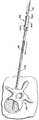
도 3은 도 1에 도시한 시스템의 일부를 형성하는 피하 접근 도구 그룹의 사시도이다.3 is a perspective view of a group of hypodermic access tools forming part of the system shown in FIG. 1.
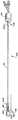
도 4a는 도 1에 도시한 시스템의 일부를 형성하는 공동 형성 도구의 사시도이다.4A is a perspective view of a cavity forming tool forming part of the system shown in FIG. 1.
도 4b는 도 1의 4B-4B 선을 따라 취한 공동 형성 도구의 카테테르 튜브의 단 면도이다.4B is a short cut of the catheter tube of the cavity forming tool taken along
도 4c는 사전에 구부러진 탐침을 갖춘 도 4a에 도시한 공동 형성 도구의 또 다른 실시예의 단면도(端面圖)이다.4C is a cross-sectional view of another embodiment of the cavity forming tool shown in FIG. 4A with a pre-bent probe.
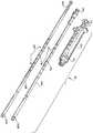
도 5는 도 1에 도시한 시스템의 일부를 형성하는 물질 도입 도구 그룹의 사시도이다.FIG. 5 is a perspective view of a group of material introduction tools forming part of the system shown in FIG. 1. FIG.
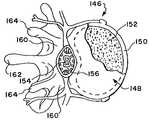
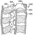
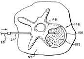
도 6 및 도 7은 인간의 척추체의 평면도 및 측면도이다.6 and 7 are top and side views of the human vertebral body.
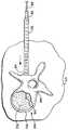
도 8은 뼈 접근 절차를 시작하기 위하여 가시 모양의 바늘 도구를 삽입하는 동안의 척추체의 평면도이다.8 is a plan view of the vertebral body during insertion of the spiny needle tool to begin the bone access procedure.
도 9 내지 도 11은 도 8에 도시한 가시 모양의 바늘 도구를 삽입한 후에 안내 핀 도구를 척추체 내에 삽입하는 단계를 보인 평면도이다.9 to 11 are plan views illustrating the step of inserting the guide pin tool into the vertebral body after inserting the needle tool in the shape of a spine shown in FIG. 8.
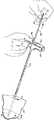
도 12는 도 9 내지 도 11에 도시한 안내 핀 도구를 삽입한 후에 손잡이를 이용하여 안내 핀 도구 위에 전개되는 폐색 도구를 전개하는 단계를 보인 사시도이다.12 is a perspective view showing a step of deploying a blockage tool deployed on the guide pin tool using a handle after inserting the guide pin tool shown in FIGS. 9 to 11.
도 13은 도 12에 도시한 폐색 도구가 전개된 상태의 척추체의 평면도이다.FIG. 13 is a plan view of the vertebral body in a state where the occlusion tool shown in FIG. 12 is deployed; FIG.
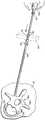
도 14는 도 12에 도시한 폐색 도구를 삽입한 후에 도 12에 도시한 손잡이를 이용하여 폐색 도구 위에 캐뉼러 도구를 전개하는 단계를 보인 사시도이다.FIG. 14 is a perspective view illustrating a step of deploying a cannula tool on the occlusion tool using the handle shown in FIG. 12 after inserting the occlusion tool shown in FIG. 12.
도 15는 도 14에 도시한 캐뉼러 도구가 전개된 상태의 척추체의 평면도이다.15 is a plan view of the vertebral body with the cannula tool shown in FIG. 14 deployed;
도 16은 도 14에 도시한 캐뉼러 도구를 삽입한 후에 캐뉼러 도구로부터 폐색 도구를 제거하여 캐뉼러 도구 및 안내 핀 도구를 적소에 두는 단계를 보인 사시도이다.FIG. 16 is a perspective view showing the steps of removing the occlusion tool from the cannula tool and inserting the cannula tool and the guide pin tool in place after inserting the cannula tool shown in FIG. 14.
도 17은 도 16에 도시한 폐색 도구 제거 단계 이후에 캐뉼러 도구 및 안내 핀 도구가 적소에 놓인 상태의 척추체의 평면도이다.17 is a plan view of the vertebral body with the cannula tool and the guide pin tool in place after the occlusion tool removal step shown in FIG.
도 18은 도 16에 도시한 폐색 도구를 제거한 후에 도 14에 도시한 손잡이를 사용하여 안내 핀 도구를 따라 캐뉼러 도구를 통해 드릴 비트 도구를 전개하는 단계를 보인 사시도이다.FIG. 18 is a perspective view illustrating the step of deploying the drill bit tool through the cannula tool along the guide pin tool using the handle shown in FIG. 14 after removing the occlusion tool shown in FIG. 16.
도 19는 도 18에 도시한 드릴 비트 도구가 손잡이의 사용을 통해 전개되어 척추체의 내부 공간 내로 통로가 형성된 척추체의 평면도이다.FIG. 19 is a plan view of the vertebral body in which the drill bit tool shown in FIG. 18 is deployed through the use of a handle to form a passageway into the internal space of the vertebral body.
도 20은 도 18에 도시한 드릴 비트 도구 및 안내 핀 도구를 제거한 후에 공동 형성 도구를 척추체 내로 전개하는 단계를 보인 사시도이다.20 is a perspective view showing the step of deploying the cavity forming tool into the vertebral body after removing the drill bit tool and the guide pin tool shown in FIG. 18.
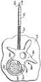
도 21은 도 20에 도시한 공동 형성 도구에 의해 지지되는 팽창 가능한 구조가 척추체의 내부 공간 내로 전개되는 척추체의 평면도이다.FIG. 21 is a plan view of the vertebral body with the expandable structure supported by the cavitation tool shown in FIG. 20 deployed into the internal space of the vertebral body; FIG.
도 22는 도 21에 접혀진 상태로 도시된 팽창 가능한 구조가 팽창되어 해면 모양의 뼈를 압축하고 공동을 형성하는 상태의 척추체의 평면도이다.FIG. 22 is a plan view of the vertebral body with the inflatable structure shown in the folded state in FIG. 21 expanded to compress the spongy bone and form a cavity;
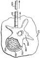
도 23은 팽창 가능한 구조를 제거한 후에 해면 모양의 뼈를 압축함으로써 형성되는 공동을 보여주는 척추체의 평면도이다.FIG. 23 is a plan view of the vertebral body showing a cavity formed by compressing the spongy bone after removal of the inflatable structure; FIG.
도 24는 도 23에 도시한 공동 내로 도입하기 위하여 선택된 물질로 채워진 도 5에 도시한 물질 도입 도구 그룹의 주사기의 사시도이다.FIG. 24 is a perspective view of a syringe of the material introduction tool group shown in FIG. 5 filled with material selected for introduction into the cavity shown in FIG.
도 25는 도 5에 도시한 물질 도입 도구 그룹의 일부를 또한 형성하는 노즐에 연결된 도 24에 도시한 주사기의 사시도이다.FIG. 25 is a perspective view of the syringe shown in FIG. 24 connected to a nozzle that also forms part of the substance introduction tool group shown in FIG. 5.
도 26은 물질을 공동 내로 도입함에 있어서 캐뉼러 도구를 통해 전개되는 도 25에 도시한 주사기 및 그에 부착된 노즐을 보인 사시도이다.FIG. 26 is a perspective view showing the syringe shown in FIG. 25 and a nozzle attached thereto, as deployed through the cannula tool in introducing material into the cavity.
도 27 및 도 28은 사용시 공동 내로 통과할 수 있도록 캐뉼러 도구 내로 물질을 분사하는 도 26에 도시한 주사기 및 그에 부착된 노즐을 각각 보인 사시도 및 평면도이다.27 and 28 are perspective and top views, respectively, of the syringe and nozzle attached to it shown in FIG. 26 for injecting material into the cannula tool to allow passage into the cavity in use.
도 29는 계량된 양의 물질이 주입되고 캐뉼러 도구로부터 주사기 및 그에 부착된 노즐이 빼내진 후의 척추체의 평면도이다.29 is a top view of the vertebral body after a metered amount of material has been injected and the syringe and nozzle attached thereto are withdrawn from the cannula tool.
도 30은 도 5에 도시한 물질 도입 도구 그룹의 일부를 형성하는, 캐뉼러 도구 내에서 전개되어 있는 탬핑 도구의 전개 상태를 보인 평면도이다.FIG. 30 is a plan view showing the deployed state of the tamping tool deployed in the cannula tool, forming part of the material introduction tool group shown in FIG. 5.
도 31은 캐뉼러 도구로부터 공동 내로 물질을 옮기고 분배하기 위하여 캐뉼러 도구 내에서 탬핑 도구를 전진하는 상태를 보인 평면도이다.FIG. 31 is a plan view showing the state of advancing the tamping tool within the cannula tool to transfer and dispense material from the cannula tool into the cavity. FIG.
도 32는 탬핑 도구 및 캐뉼러 도구가 제거된 후에 물질로 채워진 공동을 보인 척추체의 평면도이다.32 is a top view of the vertebral body showing a cavity filled with material after the tamping and cannula tools are removed.
도 33은 본 발명의 특징을 구현한 직경이 감소된 캐뉼러 도구와 그에 결합된 직경이 감소된 물질 도입 도구의 사시도이다.33 is a perspective view of a reduced diameter cannula tool embodying features of the present invention and a reduced diameter material introduction tool coupled thereto.
도 34는 사용시 도 33에 도시한 직경이 감소된 캐뉼러 도구를 사용하여 전개되는 팽창 가능한 공동 형성 구조를 갖춘 공동 형성 도구의 사시도로서, 공동 형성 도구가 그 후방 위치에 도시된 활주 도입기 슬리브를 갖춘 상태를 보인 도면이다.FIG. 34 is a perspective view of a cavity forming tool with an inflatable cavity forming structure deployed using the reduced cannula tool shown in FIG. 33 in use, the cavity forming tool having a slide introducer sleeve shown in its rear position; FIG. This figure shows the state.
도 35는 도 34에 도시한 공동 형성 도구의 사시도로서, 도입기 슬리브가 전방으로 이동하여 팽창 가능한 공동 형성 구조 위에 놓이고 그를 압축하는 상태를 보인 도면이다.FIG. 35 is a perspective view of the cavity forming tool shown in FIG. 34, with the introducer sleeve moving forward over the inflatable cavity forming structure and compressing it. FIG.
도 36은 도 35에 도시한 공동 형성 구조의 사시도로서, 도입기 슬리브(부분적으로 단면도로 도시되어 있음)가 캐뉼러 도구의 가까운 단부에 커플링 되어서 슬리브 내에서 압축된 팽창 가능한 구조를 손상 없이 직경이 감소된 캐뉼러 도구 내로 안내하는 상태를 보인 도면이다.FIG. 36 is a perspective view of the cavity forming structure shown in FIG. 35, wherein an introducer sleeve (shown in partial cross-section) is coupled to the near end of the cannula tool such that diameter of the expandable structure compressed within the sleeve can be damaged without damage; Figure showing the state of guiding into the reduced cannula tool.
도 37은 도 36에 도시한 공동 형성 구조의 사시도로서, 팽창 가능한 구조가 도입기 슬리브에 의해 캐뉼러 도구 내로 안내된 후에 뼈 내에서 전개될 수 있도록 캐뉼러 도구를 통해 전진하는 상태를 보인 도면이다.FIG. 37 is a perspective view of the cavity forming structure shown in FIG. 36, showing a state in which the expandable structure is advanced through the cannula tool such that it can be deployed in bone after being guided into the cannula tool by the introducer sleeve.
본 발명은 본 발명의 참뜻 및 특징을 벗어나지 않는 한 여러 가지 형태를 실시를 할 수 있다. 본 발명의 범위는 이하의 발명의 상세한 설명에 의해 제한되는 것이 아니라 청구의 범위에 의해 제한된다.The present invention can be embodied in various forms without departing from the spirit and features of the present invention. It is intended that the scope of the invention be limited not by this detailed description, but rather by the claims.
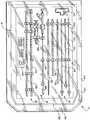
도 1 및 도 2는 기능적 도구의 시스템(10)을 보인 것이다. 사용시, 시스템의 어떤 도구는 조직을 파고 들어가고 뼈의 안쪽으로 피하 접근하기 위하여 전개된다. 뼈의 안쪽에서, 시스템(10)의 나머지 기구가 전개되어 해면 모양의 뼈 안에서 공동을 형성하며, 그 공동 내로 치료 목적의 물질이 도입되게 된다.1 and 2 show a
예시된 실시예에 있어서, 시스템(10)은 세 개의 기능적 도구 그룹(14, 16, 18)으로 된 포장 키트(12)로서 제공되어 있다. 첫번째 그룹(14)(도 3에 키트(12)의 바깥쪽에 도시되어 있음)은 뼈의 내부로 피하 접근하기 위한 도구로 구성되어 있다. 두번째 그룹(16)(도 4에 키트(12)의 바깥쪽에 도시되어 있음)은 해면 모양의 뼈 안에 공동을 형성하기 위한 도구로 구성되어 있다. 세번째 그룹(18)(도 5에 키트(12)의 바깥쪽에 도시되어 있음)은 공동 내로 물질을 도입하기 위한 도구로 구성되어 있다.In the illustrated embodiment, the
키트(12)는 여러 가지 형태를 취할 수 있다. 예시된 실시예에서, 키트(12)는 살균 포장된 어셈블리로 구성되어 있다.
각각의 기능적 도구 그룹(14, 16, 18) 및 키트(12)에 대해 이하에서 상세히 설명하기로 한다.Each
I. 피하 접근 도구 그룹I. Subcutaneous Access Tool Group
그룹(14) 내의 도구의 숫자 및 형태는 변경 가능하다. 도 3은 5 개의 도구를 보여주고 있으며, 그들 각각의 크기와 기능은 다르다.The number and shape of the tools in
A. 가시 모양의 바늘 및 안내 핀A. Spiny needles and guide pins
도 3에 도시한 바와 같이, 도구 중 하나는 종래의 가시 모양의 바늘 어셈블리(20)와 안내 핀 어셈블리(26)로 구성되어 있다.As shown in FIG. 3, one of the tools consists of a conventional
사용시, 가시 모양의 바늘 어셈블리(20)는 목표로 하는 치료 부위로 안내하는 초기 피하 경로를 설정한다. 안내 핀 도구(26)는 이 경로를 통해 전개되고, 점진적으로 커지는 도구가 뒤를 잇는다. 이에 대해서는 이하에서 상세히 설명하기로 한다.In use, the spine-shaped
가시 모양의 바늘 어셈블리(20)는 필상 돌기(24) 내에서 활주 가능하게 전개되는 탐침(22)을 포함하고 있다. 필상 돌기(24)의 게이지 직경은 예를 들어 11이지만, 사용되는 안내 핀 도구(26)의 게이지에 따라 다른 게이지 직경이 사용될 수 있다.The
사용시, 안내 핀 도구(26)는 바늘 탐침(22)과의 교환에 의해 가시 모양의 바늘 어셈블리(20)에 의해 설정된 피하 경로를 통해 전개된다. 안내 핀 도구(26)는 목표가 되는 치료 부위로 향하는 주요 경로의 설정을 안내하는 역할을 한다.In use, the
그룹(14) 내의 나머지 도구(28, 30, 32)는, 사용시 각기 다른 기능을 수행하도록 되어 있지만, 일부 공통의 특징을 가지고 있다. 이들 도구(28, 30, 32)는 각각 단단한 수술용 등급의 플라스틱이나 금속 재료로 만들어진다. 이들 도구(28, 30, 32)는 각각 가까운 단부(34)와 먼 단부(36)를 갖춘 가늘고 긴 원통형 몸체를 포함하고 있다.The remaining
B. 폐색 도구B. Occlusion Tool
도구(28)는 폐색 장치로서의 기능을 수행한다. 먼 단부(36)는 테이퍼 경사져서 침투 표면(38)을 형성하고 있다. 사용시, 표면(38)은 가까운 단부(34)에서 의사에 의해 가해진 미는 힘 또는 비트는 힘에 응답하여 부드러운 조직을 파고 들어가도록 되어 있다.The
폐색 도구(28)의 가까운 단부(34)는 플랜지가 달린 표면(40)을 제공하는데, 이것은 가까운 단부(34)의 방향으로 큰 외경에서 작은 외경으로 테이퍼 경사져 있다. 플랜지가 달린 표면(40)은 원주 방향으로 간격을 두고 배열된 치상(齒狀) 부재(42)의 어레이를 포함하고 있다.The
내부 루멘(44)은 먼 단부(36)에서 가까운 단부(34)쪽으로 폐색 도구(28)를 통해 연장된다. 내부 루멘(44)은 안내 핀 도구(26)를 수용할 수 있는 크기로 되어 있다. 이에 대해서는 이하에서 상세히 설명하기로 한다.The
C. 캐뉼러 도구C. Cannula Tools
도구(30)는 캐뉼러 또는 안내 외장으로서의 기능을 수행한다. 캐뉼러 도구(30)는 직경이 다소 크지만 폐색 도구(28)만큼 길지는 않다. 캐뉼러 도구(30)는 먼 단부(36)에서 가까운 단부(34)로 연장되는 내부 루멘(46)을 포함하고 있다. 내부 루멘(46)은 폐색 도구(28)를 수용할 수 있는 크기로 되어 있다. 내부 루멘(46)은 의사가 폐색 도구(28)에 대해 캐뉼러 도구(30)를 활주 및 회전시키거나, 반대로 캐뉼러 도구(30)에 대해 폐색 도구(28)를 활주 및 회전시킬 수 있는 크기로 되어 있다. 이에 대해서는 이하에서 상세히 설명하기로 한다.The
캐뉼러 도구(30)의 먼 단부(36)는 단부 표면(48)을 제공한다. 사용시, 캐뉼러 도구(30)의 단부 표면(48)은 가까운 단부(34)에 가해지는 미는 힘 또는 비트는 힘에 응답하여 폐색 도구 둘레의 부드러운 조직을 파고 들어갈 수 있도록 되어 있다.The
가까운 단부(34)는 확대된 피팅(50)을 지지한다. 피팅(50)은 가까운 단부(34)의 방향으로 큰 직경에서 작은 직경으로 테이퍼 경사져 있다. 폐색 도구(28) 상에서 테이퍼 경사진 플랜지(40)와 같이, 테이퍼 경사진 플랜지(50)는 원주 방향으로 간격을 두고 배치된 치상 부재(52)를 구비하고 있다. 캐뉼러 도구(30)의 테이퍼 경사진 피팅(50)은 폐색 도구(28)의 테이퍼 경사진 플랜지(40)의 최대 외경보다 큰 최대 외경을 가지고 있다.The
캐뉼러 도구(30)는 그 길이를 따라 측정된 마킹(118)을 포함하고 있다 (도 3 참도). 측정된 마킹(118)은 삽입 깊이를 측정한다. 마킹(118)은 예를 들어 1 센티 미터 간격으로 배치될 수 있다. 도 3에 도시한 바와 같이, 마킹(118)은 먼 단부(36)에서 시작하여 연속적으로 숫자가 매겨짐으로써 의사가 삽입 깊이를 첫눈에 알 수 있게 된다.
D. 드릴 비트 도구D. Drill Bit Tool
도구(32)는 드릴 비트의 역할을 행한다. 드릴 비트 도구(32)는 폐색 도구(28)와 물리적으로 동일한 치수를 갖는다. 폐색 도구(28)와 같이, 드릴 비트 도구(32)는 사용시 캐뉼러 도구(30)의 내부 루멘 내에서 활주 및 회전 운동을 할 수 있도록 되어 있다.The
드릴 비트 도구(32)의 먼 단부(36)는 기계 가공된 절단 날(54)을 포함하고 있다. 사용시 절단 날(54)은 드릴 비트 도구(32)의 가까운 단부(34)에 가해진 회전 및 길이방향 하중력에 응답하여 단단한 조직을 파고 들어가도록 되어 있다.The
가까운 단부(34)는 폐색 도구(28) 위의 플랜지(40)와 사실상 동일한 테이퍼 경사진 플랜지(56)를 제공한다. 폐색 도구(28)와 마찬가지로, 테이퍼 경사진 플랜지(56)는 가까운 단부(34)의 방향으로 큰 직경에서 작은 직경으로 변경된다. 드릴 비트 도구(32)의 테이퍼 경사진 플랜지(56)는 원주 방향으로 간격을 두고 배치된 치상 부재(58)의 어레이를 또한 포함하고 있다. 드릴 비트 도구(32)의 치상 부재(58)의 형태 및 방위는 폐색 도구(28)의 치상 부재(42)의 형태 및 방위에 대응한다.The
E. 손잡이E. Handle
그룹은 손잡이(60)를 포함하고 있다. 손잡이(60)는 기능적 도구(28, 30, 32) 를 분리 가능한 슬립 피트 방식으로 결합하여 의사가 도구를 사용할 때 도구의 조작을 편리하게 해준다.The group includes a
손잡이(60)는 성형 또는 주조된 단단한 플라스틱 또는 금속 재료로 만들어진다. 손잡이(60)는 일반인의 손에 의해 안락하게 그리고 확실하게 파지될 수 있는 형태로 되어 있다. 물론, 이러한 기능을 조절하기 위한 형상 및 크기는 변경 가능하다. 예시된 실시예에서, 손잡이(60)는 주축을 따라 가늘고 길게 배치되어 손바닥에 안락하게 파지될 수 있다.
손잡이(60)는 손잡이(60)의 중심에 일체적으로 성형되는 중심 포스트(62)를 포함하고 있다. 중심 포스트(62)는 아래로 연장되어 손잡이(60)가 T 형태를 취하게 된다.The
손잡이(60)는 중심 포스트(2) 내에서 두개의 내부 공동 또는 소켓(64, 66)을 포함하고 있다. 소켓은 손잡이(60)와 도구(28, 30, 32) 사이의 부착을 안내한다. 첫번째 및 두번째 소켓(64, 66)은 각기 다른 기능적 도구에 맞는 독특한 부착 부위를 제공할 수 있는 크기로 되어 있다.The
첫번째 소켓(64)은 형태 및 방위에 있어서 폐색 도구(28) 및 드릴 비트 도구(32)의 가까운 단부(34)에서의 치상 부재(42, 58)에 부합되는 원주방향으로 간격을 두고 배치된 그루브(68)의 어레이를 포함하고 있다. 첫번째 소켓(64)은 폐색 도구(28) 또는 드릴 비트 도구(32)의 테이퍼 경사진 플랜지(40, 56)를 받아들인다. 테이퍼 경사진 플랜지(40, 56)의 치상 부재(42, 58)는 첫번째 소켓(64)의 그루브(68)와 슬립 피트 형태로 맞물려 있다. 슬립 피트에 의해 길이방향 힘이 손 잡이(60)를 통해 도구(28, 32)에 가해지게 된다. 슬립 피트는 도구(28, 32) 및 첫번째 소켓(64)간의 상대 회전을 방지하며, 따라서 손잡이(60)에 의해 도구(28, 32)로 비트는 힘이 가해질 수 있다. 이에 의해 기계적인 장점이 증가한다.The
두번째 소켓(66)은 첫번째 소켓(64)보다 크고, 캐뉼러 도구(30)의 테이퍼 경사진 큰 피팅(50)을 수용할 수 있는 크기로 되어 있다. 두번째 소켓(66)은 형태 및 방위에 있어서 테이퍼 경사진 피팅(50)의 치상 부재(52)와 부합되는 원주 방향으로 간격을 두고 배치된 그루브(70)의 어레이를 포함하고 있다. 테이퍼 경사진 피팅(50)의 치상 부재(52)는 두번째 소켓(66)의 그루브(70)와 슬립 피트 형태로 맞물려 있다. 슬립 피트에 의해 길이방향 힘 또는 비트는 힘이 손잡이(60)를 통해 캐뉼러 도구(30)에 가해질 수 있으며, 이에 의해 기계적인 장점이 증가한다.The
도 3에 가상선으로 도시한 바와 같이, 제 1 통로(72)는 손잡이(60)의 상부를 통과하고, 중심 포스트(72)를 통과하여 첫번째 소켓(64) 내로 연장된다. 통로(72)는 첫번째 소켓(64)의 중심과 정렬하며, 안내 핀 도구(26)를 통과할 수 있는 크기로 되어 있다 (도 12 참조).As shown in phantom in FIG. 3, the
마찬가지로, 도 3에 가상선으로 도시한 바와 같이, 제 2 통로(74)는 손잡이(60)의 상부를 통과하고, 중심 포스트(62)를 통과하여 두번째 소켓(66) 내로 연장된다. 통로(74)는 두번째 소켓(66)의 중심과 정렬하며, 폐색 도구(28) 또는 드릴 비트 도구(32)를 통과할 수 있는 크기로 되어 있다 (도 14 참조).Likewise, as shown in phantom in FIG. 3, the
손잡이(60)에 대한 더욱 상세한 내용은 "신체 영역 안으로 접근하는 수지 도구용 슬립 피트 손잡이"를 발명의 명칭으로 하여 1998년 1월 27일자로 출원된 미국 특허 출원 제 09/014,229 호에 개시되어 있다.Further details of the
손잡이(60) 및 그와 결합된 도구(26, 28, 30)의 사용에 대해서는 이하에서 더욱 상세히 설명하기로 한다.The use of
II. 공동 형성 도구II. Cavity shaping tools
도 4a에 도시한 바와 같이, 그룹(16)은 캐뉼러 도구(30)를 통해 뼈 내부 위치로 전개되는 도구(76)를 포함하고 있다 (도 20 참조). 그렇게 전개되었을 때, 도구(76)는 해면 모양의 뼈 내에서 공동을 형성하는 기능을 수행한다.As shown in FIG. 4A, the
도구(76)는 다양한 방식으로 구성될 수 있다. 예시된 실시예에서, 도구(76)는 가까운 단부(80)와 먼 단부(82)를 갖춘 유연한 카테테르 튜브(78)를 포함하고 있다. 가까운 단부(80)는 손잡이 그립(84)을 지지함으로써 카테테르 튜브(78)의 파지 및 조정을 용이하게 한다. 카테테르 튜브(78)의 재료로는 캐뉼러 도구(30)를 통해 전진할 수 있는 것이라면 어떠한 재료를 이용하여도 좋다. 카테테르 튜브(78)는, 예를 들어 비닐, 나일론, 폴리에틸렌, 이오노머, 폴리우레탄, 폴리에틸렌 테트라프탈레이트(PET) 등의 유연하고 수술용 등급인 플라스틱 재료를 사용하여 만들 수도 있다. 카테테르 튜브(78)는 강성을 높이고 조작성을 높이기 위하여 더욱 단단한 재료를 또한 포함할 수도 있다. 이러한 목적으로 사용될 수 있는 더욱 단단한 재료로는 스테인리스 강, 니켈 티타늄 합금 (NitinolTM 재료) 및 기타 금속 합금 등이 있다.
도구(76)의 먼 단부(82)는 팽창 가능한 구조(86)를 지지한다. 예시된 실시예에 있어서, 팽창 가능한 구조(86)는 폴리우레탄 또는 엘라스토머 (예를 들어, 실리 콘 또는 나일론) 재료로 만들어져 있다. 구조(86)는 예를 들어 종래의 열형성 기법의 사용을 통해 열 및 압력에 노출시켜 소정의 형상을 취할 수 있도록 예비성형된다.The
도 4b에 도시한 바와 같이, 카테테르 튜브(78)는 구조(86)의 내부와 소통하는 내부 루멘(88)을 포함하고 있다. 카테테르 튜브(78)의 가까운 단부(80)의 피팅(90)(도 4b 참조)은 루멘(88)과 소통하고 있다. 피팅(90)은 루벤(88)을 유체 소오스(92), 예를 들어 살균 염수 (도 21 참조) 또는 방사선 불투과성 조영제 소오스에 커플링 연결한다.As shown in FIG. 4B, the
유체는 압력이 가해진 상태에서 소오스(92)로부터 구조(86) 내로 도입되어 구조(86)를 팽창시킨다. 뼈의 내부를 팽창시키는 동안, 구조(86)에 맞게 선택된 재료는 변형에 견디게 됨으로써 뼈 안쪽의 팽창된 형상은 대기와 소통하는 상태에서의 뼈의 바깥쪽의 팽창된 형상에 대응하게 된다. 이에 의해 의사는 뼈 안쪽의 팽창된 형상이 중요한 점에 있어서 유사하다는 확신을 가지고 대기와 소통하는 상태에서 목표가 되는 치료 결과를 충족하는데 필요한 팽창 형성을 갖는 구조(86)를 선택할 수 있게 된다. 뼈의 안쪽의 변형을 막으면서 그 체적을 팽창시키는 것 외에도, 구조(86)의 재료는 해면 모양의 뼈와 접촉할 때 마모, 파열 등에 견딜 수 있다.Fluid is introduced from the
구조(86)의 형상은, 뼈 안쪽에서 팽창되었을 때, 의사가 처치되어야 할 부위의 형태 및 구조를 고려하여 선택하게 된다. 압축되는 해면 모양의 뼈의 형상 및 뼈가 부적절하게 이동하는 경우 손상을 입을 수도 있는 국부적인 조직은 일반적으로 전문의가 그 부위 및 그에 대한 질병 또는 상해에 대한 지식에 기초하여 인체 해부학 교과서를 이용하여 이해할 수 있다. 의사는 예를 들어 평면 필름 엑스레이, 형광 투시 엑스레이나 MRI 또는 CT 촬영을 이용하여 목표가 되는 뼈의 형태에 대한 사전 분석에 기초하여 뼈 안쪽의 팽창 형상을 또한 선택할 수 있다. 뼈 안쪽의 팽창된 형상은, 예를 들어 적절한 물질로 채워졌을 때 처치되는 뼈의 영역에 걸쳐 지지력을 제공하는 공동의 형성을 최적화하기 위하여 선택된다.The shape of the
일반적인 지침으로서, 골절 (또는 골절의 위험)을 야기하는 뼈의 질병이 (골다공증에서와 같이) 해면 모양의 뼈 질량의 손실인 경우, 뼈 안쪽의 구조(86)의 팽창된 형상의 선택은 해면 모양의 뼈의 체적의 30% 내지 90%는 압축되어야 한다는 점을 고려하여 행해져야 한다. 또 다른 일반적인 지침은 목표가 되는 골절된 뼈 부위가 옮겨지거나 눌려진 양이다. 해면 모양의 뼈 영역 내의 구조(86)의 팽창은 골절이 일어나기 전에 차지하였던 해부학적 위치로 또는 그 근처로 골절된 피질 벽을 상승시키거나 밀어 넣을 수 있다.As a general guideline, if the disease of the bone causing the fracture (or the risk of fracture) is a loss of spongy bone mass (as in osteoporosis), the choice of the expanded shape of the
예시된 실시예(도 4a 참조)에서, 구조(86)는 예비 형성된 모래시계 또는 땅콩 형상을 취하고 있다. 이 형상은 척추체 내의 구조(86)의 전개를 고려하여 선택된다. 이에 대해서는 이하에서 상세히 설명하기로 한다.In the illustrated embodiment (see FIG. 4A),
캐뉼러 도구(30)를 통해 구조(86)의 전개를 더욱 쉽게 하기 위하여, 카테테르 튜브(78)는 제 2 의 내부 루멘(94)을 포함하고 있다. 루멘(94)은 카테테르 튜브(78)의 가까운 단부(80)의 제 2 피팅(98)으로부터, 카테테르 튜브(78)의 몸체를 통해, 그리고 구조(86)의 내부를 통하여 구조(86)의 선단부(172)로 연장된다. 루멘(94)은 성형 플라스틱 또는 스테인리스 강 재료로 만들어질 수 있는 단단한 탐침(96)을 수용한다. 탐침(96)은 피팅(98)을 통해 루멘(94) 내로 삽입되며, 탐침(96)을 움직이지 못하도록 고정하는 나사가 형성된 커플링(100)을 포함하고 있다. 탐침(96)은 캐뉼러 도구(30)를 통과하여 목표가 되는 조직 부위에 이르는 동안 구조(86)를 소정의 말단에서 똑바른 상태로 유지하는 기능을 한다. 일단 구조(86)가 캐뉼러 도구(30)를 떠나서 뼈 안쪽에 놓이게 되면, 탐침(96)이 (도 4a에서 화살표 174로 나타낸 바와 같이) 빼내어진다. 이에 의해 카테테르 튜브(78)에 대한 정상적인 휨성이 회복되고, 뼈 안쪽에서의 구조(86)의 조작이 용이해진다. 탐침(96)이 빼내어지면, 루멘(94) 또한 헹굼 액체를 도입하거나 뼈에서 나온 부스러기를 빨아내기 위한 통로로서의 기능을 할 수 있다.To further facilitate deployment of
예시된 실시예에서, 탐침(96)은 곧게 뻗은 상태로 치우쳐 있다. 또 다른 실시예(도 4c 참조)에 있어서는, 탐침(102)이 사전 형성된 메모리를 구비할 수 있어서 통상적으로 그 말단 영역을 구부릴 수 있다. 메모리의 극복을 통해 캐뉼러 도구(30) 내에서 한정될 때 탐침(102)을 곧게 할 수 있다. 그러나, 구조(86) 및 사전 형성된 탐침(102)의 말단 영역이 캐뉼러 도구(30)를 떠나 전진하여 목표가 되는 영역 내로 들어감에 따라, 사전 형성된 메모리는 탐침(102)의 말단 영역을 굽히고, 따라서 팽창 가능한 구조(86)의 주축을 시프트하게 된다. 구조(86)의 내부에 위치하고 있는 사전에 구부러져 있는 탐침(102)에 의해 구조(86)의 방향이 변경될 수 있어서 목표가 되는 영역과의 해부학적 정렬이 더욱 양호해진다.In the illustrated embodiment, the
해면 모양의 뼈와 다른 내부 신체 영역 내에 공동을 형성할 수 있는 다른 형태의 도구가 "내부 신체 영역 내에 공동을 형성하기 위한 구조 및 방법"을 발명의 명칭으로 하여 1998년 4월 6일자로 출원된 미국 특허 출원 제 09/055,805 호에 개시되어 있다.Another type of tool capable of forming cavities in spongy bones and other internal body regions was filed April 6, 1998, entitled "Structures and Methods for Forming Cavities in Internal Body Regions". US Patent Application No. 09 / 055,805.
III. 물질 도입 도구 그룹III. Substance introduction tool group
그룹(18)은 구조(86)에 의해 형성된 공동 안쪽으로 선택된 물질을 이송하고 압축하는 도구(104, 106, 108)를 포함한다. 공동 내의 물질은 소정의 치료 결과, 예를 들어 조직 덩어리의 대체, 뼈에 사용되는 내부 지지체의 보완, 약물의 전달 또는 그 조합을 제공한다. 따라서, 이러한 기능을 수행하기 위한 물질은 예를 들어 뼈 시멘트, 자가 이식 조직, 타가 이식 조직, 합성 뼈 대용품 및 약물 또는 그 조합을 포함하여 경화 상태로 세팅된 재료 중에서 선택될 수 있다.
예시된 실시예에서, 그룹(18)은 물질 주입 도구(104, 106) 및 물질 탬핑 도구(108)로 구성된다. 상기 도구들은 낮은 압력에서, 예를 들어, 약 360 psi 이하의 압력에서 물질을 전달한다.In the illustrated embodiment,
A. 저압 물질 주입 도구A. Low Pressure Material Injection Tool
예시된 실시예에서, 물질은 종래의 주사기(104)에 의해 주입된다. 이 주사기에는 특별히 설계된 주입 노즐(106)이 커플링되어 있다. 푸시 플런저를 갖춘 수동 조작 주사기를 사용할 수 있다. 그렇지 않으면, 수동으로 작동될 수도 있고 기계적인 액추에이터에 의해 작동될 수 있는 나사가 형성된 플런저를 갖춘 LeVeen Inflation 주사기를 사용할 수 있다.In the illustrated embodiment, the substance is injected by
예시된 실시예에서, 주사기(104)는 투명한 플라스틱 재료로 만들어진다. 주사기(104)는 주입될 물질을 수용하는 체임버(110)를 포함하고 있다. 물질은 수동으 로 전진하는 주사기 피스톤(112)에 의해 체임버(100)로부터 짜내어진다 (도 25 참조).In the illustrated embodiment, the
주입 노즐(106)은 나사가 형성된 커넥터(114)에 의해 주사기(104)의 단부에 연결되어 있다 (도 25 참조). 예시된 실시예에서, 노즐(106)은 폴리에틸렌이나 기타의 적절한 폴리머 따위의 유연한 불활성 플라스틱 재료로 만들어진다. 그렇지 않으면, 노즐(106)은 단단한 플라스틱 또는 금속 재료로 만들어질 수 있다.The
주입 노즐(106)은 캐뉼러 도구(30)를 통해 전진할 수 있는 크기로 되어 있다 (도 26 참조). 노즐(106)은 그 길이를 따라 측정된 마킹(116)을 포함하고 있다. 마킹(116)은 캐뉼러 도구(30)의 마킹(118)에 대응하도록 1 센티미터 간격으로 배치될 수 있다. 따라서, 캐뉼러 도구(30) 내의 노즐의 상대 위치가 측정될 수 있다. 마킹(118)은 예를 들어 세트 포인트(176)를 포함할 수 있다. 캐뉼러 도구(30)의 가까운 단부(34)에서의 세트 포인트(176)의 정렬은 노즐(106)의 먼 단부가 캐뉼러 도구(30)의 먼 단부와 정렬된 상태로 배치되어 있음을 나타낸다. 이러한 배열에 있어서, 마킹(118)은 세트 포인트(176)에 가까워지면서 양수로 연속적으로 표시되며, 세트 포인트(176)에서 멀어지면서 음수로 연속적으로 표시된다. 따라서 의사는 한눈에 노즐(106)의 먼 단부의 위치를 알아 차릴 수 있게 되어, 캐뉼러 도구(30)의 먼 단부(36)에서 얼마나 멀리 떨어져 있는지, 얼마나 가까이 위치해 있는지 파악할 수가 있다.
사용시, 노즐(106)의 먼 단부는 목표가 되는 조직 영역 내에 형성된 공동 내의 캐뉼러 도구(30)의 먼 단부(36) 위에 위치한다. 도 5에 도시한 바와 같이, 노즐(106)의 먼 단부는, 플라스틱 재료로 만들어진 경우, 적어도 하나의 방사선 불투과성 마커(208)를 지지함으로써, 신체 내에서의 노즐 위치를 원격적으로 시각화할 수 있다. 주사기(104)는 사전 설정된 양의 물질을 노즐(106)을 통해 낮은 압력으로 공동 내로 방출한다. 물질이 공동을 채움에 따라, (여전히 물질을 방출하고 있는) 노즐은 공동으로부터 후퇴하고 캐뉼러 도구(30) 내로 들어간다. 이러한 기능 및 결과에 대한 상세한 내용은 이하에서 설명된다.In use, the far end of the
B. 물질 탬핑 도구B. Material Tamping Tools
그룹(18)은 물질 탬핑 도구(108)를 또한 포함한다. 탬핑 도구(108)는 일반적으로 단단한 불활성 플라스틱 또는 금속 재료로 만들어진다. 탬핑 도구(108)는 캐뉼러 도구(30) 내로 전진할 수 있는 크기로 되어 있다 (도 30 참조). 탬핑 도구(108)의 자유 단부(124)는 사용 중에 탬핑 도구(108)의 파지가 용이하도록 늑골형태의 부재가 부착되거나 그러한 윤곽을 가지고 있다.
탬핑 도구(108)는 그 길이를 따라 측정된 마킹(122)을 포함하고 있다. 마킹(116)은 예를 들어 캐뉼러 도구(30)의 마킹(118)에 대응하도록 1 센티미터 간격으로 배치될 수 있다. 따라서, 캐뉼러 도구(30) 내의 탬핑 도구(108)의 상대 위치가 측정될 수 있다. 노들(106)과 마찬가지로, 탬핑 도구(108)의 마킹(122)은 탬핑 도구(108)의 먼 단부가 캐뉼러 도구(30)의 먼 단부(36)와 정렬하는 때를 보여주는 세트 포인트(178)를 포함하고 있다. 또한 노즐(106)과 마찬가지로, 탬핑 도구(108)의 마킹(122)은 세트 포인트(178)에 가까워지면서 양수로 연속적으로 표시되며, 세트 포인트(178)에서 멀어지면서 음수로 연속적으로 표시된다. 따라서 의 사는 한눈에 탬핑 도구(108)의 단부의 위치를 알아 차릴 수 있게 되어, 캐뉼러 도구(30)의 먼 단부(36)에서 얼마나 멀리 떨어져 있는지 얼마나 가까이 위치해 있는지 파악할 수가 있다. 도 5에 또한 도시한 바와 같이, 탬핑 도구(108)의 단부는, 플라스틱 재료로 만들어진 경우, 적어도 하나의 방사선 불투과성 마커(210)를 지지함으로써, 신체 외부로부터의 위치를 시각화할 수 있다.The
노즐(106)을 캐뉼러 도구(30)로부터 빼낸 후에, 잔류 물질이 캐뉼러 도구(30) 내에 남아 있게 된다. 탬핑 도구(108)의 목적은 잔류 물질을 캐뉼러 도구(30)의 먼 단부(36) 밖으로 옮기고 공동 내로 운반하여서 뼈 내에 과도한 압력을 가함이 없이 공동을 채우는 것이다. 따라서, 탬핑 도구(108)는 캐뉼러 도구(30)로부터 잔류 물질을 제거하여, 소정량의 물질이 공동 내로 전달될 수 있도록 하는 기능을 한다. 탬핑 도구(108)에 의한 캐뉼러 도구(30)로부터의 잔류 물질의 제거를 통해 캐뉼러 도구(30)의 제거 시에 주변 조직 영역으로 물질이 누출되는 것이 또한 방지된다. 탬핑 도구(108)는 과도한 압력 없이 공동 내에서 물질을 균일하게 또한 압축한다. 이들 기능 및 결과에 대한 더욱 상세한 사항은 이하에서 논의된다.After removing the
IV. 키트IV. Kit
도 1 및 도 2에 도시한 바와 같이, 키트(12)는 예를 들어 다이 절단된 판지, 플라스틱 시트 또는 열가소성 플라스틱 재료로 만들어진 내부 트레이(126)를 포함하고 있다. 트레이(126)는 간격을 두고 배치된 탭(128)을 포함하고 있는데, 이 탭은 사용에 앞서 행해지는 살균 및 보관 시에 안전한 위치에 여러가지 도구를 유지한다.As shown in FIGS. 1 and 2, the
살균 어셈블리로서 포장된 경우, 외부 환경과 접촉하지 않도록 트레이(126)를 격리시키기 위하여 열 등으로 그 주변이 밀봉되어 있는 내부 랩(130)을 포함한다. 내부 랩의 일단부는 수술실 내와 같은 살균 환경에서 바람직하게 발생할 수도 있는 사용 순간의 트레이(126)로의 즉각적인 접근을 제공하는 종래의 벗김 방식 밀봉 부재(132)를 포함한다.When packaged as a sterile assembly, it includes an
살균 어셈블리로서 포장된 경우, 키트(12)는 내부 랩(130)을 둘러싸기 위하여 열 등에 의해 그 주변이 또한 밀봉되어 있는 외부 랩(134)을 또한 포함한다. 외부 랩의 일단부는 내부 랩(130) 및 그 내용물로의 접근을 제공하기 위하여 종래의 벗김 방식 밀봉 부재(136)를 포함한다. 외부 랩(134)은 키트(12)의 내용물의 살균 상태를 손상시킴이 없이 긴급 사용이 필요할 때 내부 랩으로부터 제거될 수 있다.When packaged as a sterile assembly, the
도 2에 도시한 바와 같이, 각각의 내부 및 외부 랩(130, 134)은 그 주변이 밀봉된 상부 시트(138) 및 하부 시트(140)를 포함하고 있다. 예시된 실시예에서, 상부 시트(138)는 키트(12)의 내용물을 시각적으로 확인할 수 있는 폴리에틸렌이나 MYLAR (등록상표) 재료 등의 투명한 플라스틱 필름으로 만들어져 있다. 바닥 시트(140)는 예를 들어 (듀폰에서 나온) TYVEK (등록상표) 플라스틱 재료 와 같은 ETO 살균 가스가 투과할 수 있는 재료로 만들어져 있다.As shown in FIG. 2, each of the inner and
예시된 실시예에서, 트레이(126)는 의사가 원하는 과정을 수행할 수 있도록 배열되는 순서적으로 그리고 조직적으로 정리된 레이아웃 형태의 도구 그룹(14, 16, 18)을 제공한다. 예를 들어, 의도하는 사용 순서에 따라 위에서 아래의 순서로 도구 그룹(14, 16, 18)을 제공할 수 있다. 예를 들어, 전형적인 뼈 접근 과정 (이 에 대해서는 이하에서 더욱 상세히 설명된다) 에서, 가시 모양의 바늘 어셈블리(20)의 탐침(22) 및 필상 돌기(24)가 먼저 전개되고, 이어서 안내 핀 도구(26)가 전개되고, 그 다음에 폐색 도구(28)가 전개되고, 캐뉼러 도구(30)가 전개되고, 드릴 비트 도구(32)가 전개되고, 그 다음에 공동 형성 도구(76)가 전개되고, 주사기(104) 및 노즐(106) 도구가 전개되고, 마지막으로 탬핑 도구(108)가 전개된다. 따라서, 트레이(126)는 이들 도구 및 구성 요소를 위에서 아래의 순서로, 즉 가시 모양의 바늘 어셈블리(20)가 가장 위에 놓이고, 그 다음에 안내 핀 도구(26)가 놓이고, 이어서 폐색 도구(28)가 놓이고 가장 아래에는 탬핑 도구(108)가 놓이는 형태로 포장한다.In the illustrated embodiment, the
이러한 레이아웃에 있어서, 손잡이(60)는 접근 도구 그룹(14)의 측면에 포장된다. 트레이(126)는 키트(12) 내에 포함된 구성요소를 확인하는 기록 라벨(도시 안됨)을 포함할 수도 있다. 키트(12)는 소정의 절차를 수행하기 위하여 키트(12)의 내용물을 사용하는 설명서(144)를 트레이(126) 내에 포함하는 것이 또한 바람직하다. 설명서(144)에 기술될 수 있는 바람직한 절차에 대해서는 이하에서 상세히 설명하기로 한다.In this layout, the
살균 어셈블리로서 포장되었을 때, 설명서(144)는 일회의 사용 후에 성능 및 효과가 떨어지는 키트(12)의 내용물의 재사용을 명확하게 막기 위하여 "환자에 대해 1회만 사용할 것"이라는 경고문을 또한 포함할 수도 있다. 가시 모양의 바늘 어셈블리(20), 공동 형성 도구(76) 및 물질 도입 도구(104, 106, 108)는 이러한 이유로 1회의 사용 후에는 폐기되어야 한다. 설명서(144)는 키트(12)의 적어도 이들 내 용물을 재살균하지 못하도록 하는 확실한 주의를 제공하는 것이 또한 바람직하며, 적용 가능한 생물제제 폐기 절차에 따라 사용 후에 키트(12)의 적어도 이들 내용물을 폐기할 것을 의사에게 알리는 것이 바람직하다.When packaged as a sterile assembly, the
살균 키트(12) 내에 포장된 도구 그룹(14, 16, 18)에 의해 의사는 내용물이 살균되어 있고, 이전에 사용된 적이 없음을 확인할 수 있다. 따라서 의사는 도구 그룹이 설정된 성능 및 살균 규격을 충족하고 있음을 확신하게 된다.The tool groups 14, 16, 18 packaged in the
키트(12) 내에 포함된 여러가지 도구는 여러 개의 작은 기능적 키트로 포장될 수 있다. 예를 들어, 제 1 키트는 접근 도구 그룹(14)을 포장할 수 있고, 제 2 키트는 공동 형성 도구 그룹(16)을 포장할 수 있고, 제 3 키트는 물질 도입 도구 그룹(18)을 포장할 수 있다. 도 1 및 도 2는 여러가지 가능한 실시예 중 하나를 예시한 것이다.The various tools included in
V. 시스템의 사용V. Use of the System
이하에서는 뼈의 치료 관점에서 키트(12) 내에 포장된 도구 그룹(14, 16, 18)의 사용에 대해 설명하기로 한다. 이것은 그룹(14, 16, 18)의 도구가 이러한 목적에 바람직하게 사용될 수 있기 때문이다. 단독으로 또는 상호 연합하여 사용되는 하나 이상의 도구 그룹은 신체의 다른 내부 영역에서의 다른 진단 또는 치료 기능을 수행할 수 있다.The use of
특히, 도구 그룹(14, 16, 18)은 인간의 척추의 치료와 관련하여 설명된다. 그러나, 이러한 도구 그룹의 사용은 인간의 척추에만 제한되는 것은 아니다. 도구 그룹(14, 16, 18)은 수지 도구와 함께 다양한 인간 또는 동물의 뼈 형태를 치료하 는데 사용될 수 있다.In particular, the
A. 척추체A. Vertebrate
도 6 및 도 7에 도시한 바와 같이, 전형적인 척추(146)는 척추체(148)를 포함하고 있다. 이 척추체는 척추(146)의 전방 (예를 들어, 가슴) 쪽 위에서 연장된다. 척추체(148)는 타원 형상을 취하고 있다. 척추체(148)는 압축 피질 뼈(150)로부터 형성된 외부를 포함하고 있다. 피질 뼈(150)는 그물 형태의 해면 모양의 또는 스펀지 형태의 뼈(152) (골수 뼈 또는 결체 조직 돌기 뼈로도 불림)의 내부 체적을 둘러싼다.As shown in FIGS. 6 and 7, a
척수(154)는 척추(146)의 추관(156)을 통과한다. 척추 아치(158)는 추관(156)을 둘러싼다. 척추 아치(158)의 육경(160)은 척추체(148)와 결합한다. 왼쪽 및 오른쪽 가로 프로세스(164)에서와 같이, 가시 모양의 프로세스(162)는 척추 아치(158)의 후방으로부터 연장된다.Spinal cord 154 passes through
B. 척추체의 치료B. Treatment of vertebral bodies
전형적인 절차가 수행되는 동안, 환자는 수술대 위에 놓인다. 의사의 선택에 따라, 환자는 수술대 위에서 얼굴을 아래로 하여 엎드릴 수도 있고, 옆으로 누울 수도 있고, 비스듬하게 누울 수도 있다.During the typical procedure, the patient is placed on the operating table. Depending on the doctor's choice, the patient may lie face down on the operating table, lie on the side, or lie down at an angle.
의사는 키트(12)의 외부 및 내부 랩(130, 134)을 제거하고, 사용을 위해 트레이(126)를 외부로 노출시킨다. 의사는 트레이(126)로부터 가시 모양의 바늘 어셈블리(20)를 취한다. 도 8에 도시한 바와 같이, 의사는 환자의 등 안쪽의 부드러운 조직(ST) 내로 가시 모양의 바늘 어셈블리(20)를 도입한다. 방사선 또는 CT 관측을 행하는 동안, 의사는 가시모양의 바늘 어셈블리(20)를 부드러운 조직을 통해 목표가 되는 척추(146) 내로 전진시킨다. 의사는 어셈블리(20)를 통해 국부 마취제, 예를 들어 리도케인을 투여한다. 몇몇 경우에 있어서, 의사는 다른 형태의 마취를 선호할 수도 있다.The surgeon removes the outer and
의사는 가시 모양의 바늘 어셈블리(20)가 목표가 되는 척추체(148)의 피질 뼈(150) 및 해면 모양의 뼈(152)를 파고 들어갈 수 있도록 조정한다. 침투 두께는 척추체(148)의 대략 60% 내지 95%인 것이 바람직하다.The surgeon adjusts the spine-shaped
도 8은 후측면 접근으로 불리는 척추체(148)의 측부를 통해 해면 모양의 뼈에 접근하는 것을 보인 것이다. 그러나, 액세스는 트랜스퍼디큘러 접근으로 불리는 육경(160)을 통해 이루어질 수도 있다. 접근의 형태는 치료 목적 또는 다른 이유에 기초하거나 의사의 선택에 기초한다.8 shows access to a spongy bone through the side of the
도 9에 도시한 바와 같이, 해면 모양의 뼈(152) 내에 가시 모양의 바늘 어셈블리(20)를 위치시킨 후에, 의사는 필상 돌기(24)를 고정하고 탐침(22)을 빼낸다. 의사는 트레이(126)로부터 안내 핀 도구(26)를 취한다. 도 10에 도시한 바와 같이, 여전히 필상 돌기(24)를 고정한 상태에서, 의사는 필상 돌기(24)를 통해 안내 핀 도구(26)를 활주시켜서 해면 모양의 뼈(152) 속으로 안내한다. 그런 다음, 의사는 필상 돌기(24)(도 11 참조)를 제거하고, 안내 핀 도구(26)를 해면 모양의 뼈(152) 안에서 전개된 채로 둔다.As shown in FIG. 9, after placing the spine-shaped
그 다음에, 의사는 트레이(126)로부터 폐색 도구(28) 및 손잡이(60)를 취한다. 의사는 안내 핀 도구(26) 위에서 폐색 도구(28)를 활주시키는데, 먼 단부를 먼 저 활주 시킨다. 의사는 제 1 통로(72)와 손잡이(60)의 첫번째 소켓(64)을 통해 안내 핀 도구(26)를 활주시킨다. 도 12에 도시한 바와 같이, 의사는 위에서 설명한 대로 첫번째 소켓(64)과 테이퍼 경사진 플랜지(40) 사이에서의 슬립 피트를 달성할 때까지, 폐색 도구(28)의 테이퍼 경사진 플랜지(40)를 향해 안내 핀 도구(26)를 따라 손잡이(60)를 활주 시킨다. 그러면 폐색 도구(28)를 사용할 수 있는 준비가 된 것이다.The surgeon then takes the
도 12에 도시한 바와 같이, 의사는 환자의 등에 작은 절개 부위(I)를 형성한다. 의사는 손잡이(60)에 길이방향 힘을 가하는 동안 손잡이(60)를 비튼다. 이에 따라, 폐색 도구(28)의 표면(38)이 회전하고, 절개 부위(I)를 통해 부드러운 조직(ST)을 파고 들어간다. 의사는 손잡이(60)를 또한 부드럽게 두드리거나 손잡이(60)에 별도의 적절한 길이방향 힘을 가하여 안내 핀 도구(26)를 따라 부드러운 조직을 통해 폐색 도구(28)를 밀어 넣음으로써 입구 부위에 이를 수 있다 (도 13 참조). 의사는 적절한 가격 도구를 이용하여 손잡이(60)를 두드림으로써 폐색 도구(28)의 표면(30)을 척추체(148)의 옆으로 밀어 넣어서 적소에 고정할 수도 있다 (도 13 참조).As shown in Fig. 12, the doctor makes a small incision site I on the back of the patient. The surgeon twists the
그런 다음 의사는 폐색 도구(28)에서 멀어지도록 안내 핀 도구(26)를 따라 손잡이(60)를 활주 시킴으로써 테이퍼 경사진 플랜지(40)가 첫번째 소켓(64)에서 분리된다. 그런 다음, 의사는 손잡이(60)를 활주시켜 안내 핀 도구(26)에서 완전히 분리시킨다.The physician then slides the
의사는 트레이(126)로부터 캐뉼러 도구(30)를 취한다. 도 14에 도시한 바와 같이, 의사는 안내 핀 도구(26) 위에서 캐뉼러 도구(30)를 활주시키는데 먼 단부를 먼저 활주 시키며, 단부 표면(48)과 부드러운 조직(ST) 사이의 접촉이 일어날 때까지 폐색 도구(28) 위에서 더욱 활주 시킨다. 그런 다음 의사는 제 2 통로(74)와 손잡이(60)의 두번째 소켓(66)을 통해 안내 핀 도구(26)와 폐색 도구(26)를 활주 시킨다. 의사는 앞서 설명한 바와 같이 두번째 소켓(66)과 테이퍼 경사진 피팅(50) 사이에 슬립 피트가 발생할 때까지 캐뉼러 도구(30)의 테이퍼 경사진 피팅(50)을 향해 손잡이(60)를 활주 시킨다. 그러면 캐뉼러 도구(30)를 사용할 수 있는 준비가 된 것이다.The physician takes the
도 14에 도시한 바와 같이, 의사는 손잡이(60)에 비트는 힘 및 길이방향 힘을 적절히 가하여 폐색 도구(28)를 따라 부드러운 조직(ST)을 통해 캐뉼러 도구(30)를 회전 및 전진 시킨다. 도 15에 도시한 바와 같이, 캐뉼러 도구(30)의 단부 표면(48)이 피질 뼈와 접촉하게 되면, 의사는 가격 도구를 이용하여 손잡이(60)를 적절하게 두드려서 단부 표면을 척추체(148)의 옆으로 전진시키고 적소에 고정할 수 있게 된다.As shown in FIG. 14, the surgeon applies the twisting and longitudinal forces to the
도 16에 도시한 바와 같이, 의사는 폐색 도구(28)를 활주시켜 안내 핀 도구(26)에서 분리시켜서 폐색 도구(28)를 빼낸다. 이에 의해 도 17에 도시한 바와 같이 안내 핀 도구(26) 및 캐뉼러 도구(30)가 적소에 놓이게 된다. 그런 다음 의사는 캐뉼러 도구(30)로부터 멀어지게 안내 핀 도구(26)를 따라 손잡이(60)를 활주 시킴으로써 테이퍼 경사진 피팅(50)이 두번째 소켓(66)에서 분리된다. 그런 후에 의사는 손잡이(60)를 활주 시켜 안내 핀 도구(26)에서 완전히 분리시킨다.As shown in FIG. 16, the surgeon slides the
이제 의사는 트레이(126)로부터 드릴 비트 도구(32)를 취한다. 도 18에 도시한 바와 같이, 의사는 기계 가공된 표면(54) 및 뼈 조직 사이의 접촉이 일어날 때까지 캐뉼러 도구(30)를 통하여 먼 단부부터 시작하여 안내 핀 도구(26) 위에서 드릴 비트 도구(32)를 활주 시킨다. 도 18에 도시한 바와 같이, 의사는 다음으로 제 1 통로(72)와 손잡이(60)의 첫번째 소켓(64)을 통해 안내 핀 도구(26)를 안내한다. 의사는 앞서 설명한 바와 같이 첫번째 소켓(64) 및 테이퍼 경사진 플랜지(56) 사이에서 슬립 피트가 발생할 때가지 드릴 비트 도구(32)의 테이퍼 경사진 플랜지(56)를 향해 안내 핀 도구(26)를 따라 손잡이(60)를 활주 시킨다. 그러면 드릴 비트 도구(32)의 사용 준비가 완료된다.The physician now takes the
도 18에 도시한 바와 같이, 엑스레이(또는 다른 외부 시각화 시스템)의 도움을 받아 의사는 손잡이(60)에 적절한 비트는 힘 및 길이방향 힘을 가하여 드릴 비트 도구(32)의 절단 날(54)을 회전 및 전진시켜서 뼈 조직을 관통하여 해면 모양의 뼈(152) 안으로 완전히 들어가는 통로(166)(도 19 참조)를 형성한다. 드릴 가공된 통로(166)는 척추체(148)에 걸쳐 95% 이상으로는 연장되지 않는 것이 바람직하다.As shown in FIG. 18, with the help of an x-ray (or other external visualization system), the surgeon applies the appropriate twisting and longitudinal forces to the
이제 의사는 드릴 비트 도구(32)에서 멀어지도록 안내 핀 도구(26)를 따라 손잡이(60)를 활주 시켜서 첫번째 소켓(64)으로부터 테이퍼 경사진 플랜지(56)를 분리시킨다. 의사는 손잡이(60)를 더욱 활주 시켜서 안내 핀 도구(26)로부터 완전히 분리시킨다.The surgeon now slides the
이제 의사는 드릴 비트 도구(32) 및 안내 핀 도구(26)를 제거하여 캐뉼러 도구(30) 만을 제 위치에 둘 수 있다. 드릴 비트 도구(32)에 의해 형성된 통로(166) 는 그대로 유지된다. 이렇게 해서, 해면 모양의 뼈(152)에 대한 피하 접근이 달성된다.The surgeon can now remove the
이제 의사는 트레이(126)로부터 공동 형성 도구를 취할 수 있다. 도 20에 도시한 바와 같이, 의사는 캐뉼러 도구(30) 및 통로(166)를 통해 척추체(148)의 내부로 팽창 가능한 구조(86)를 전진 시킬 수 있다. 이것은 도 21에 또한 도시되어 있다. 구조(86)는 전개가 행해지는 동안에는 접혀져 있고 팽창은 되지 않은 상태에 놓인다. 탐침(96, 102)은 카테테르 튜브(78)의 루멘(94) 내에 삽입되어, 캐뉼러 도구(30)를 통과하는 동안 구조(86)를 더욱 단단한 상태로 유지한다.The surgeon can now take the cavity forming tool from the
도 20에 가상선으로 도시한 바와 같이, 필요하다면 의사는 손잡이(60)를 캐뉼러 도구(30)에 다시 연결하여 구조(86)가 전개되는 동안 캐뉼러 도구(30)를 더욱 안정되게 유지할 수 있다. 손잡이의 제 2 통로(74)는 접혀질 때 카테테르 튜브(78) 및 구조(86)를 수용한다.As shown in phantom in FIG. 20, if necessary, the surgeon can reconnect the
도 21에 도시한 바와 같이, 구조(86)는 통로(166) 내에서 원하는 방향으로 향한다. 앞서 설명한 바와 같이, 구부러진 탐침(102)은 이러한 과제를 수행하는데 있어 일조를 한다. 방위 결정을 행하기 전에, 행하는 동안, 그리고 행한 후에 탐침(102)은 (도 21에 도시한 바와 같이) 빼내어져서 루벤(94)을 개방함으로써 헹굼 액체 또는 흡출 압력이 통과하는데 사용될 수 있다.As shown in FIG. 21, the
살균액은 가압된 상태로 소오스(92)로부터 루멘(88)을 통해 구조(86) 내로 이송된다. 도 22에 도시한 바와 같이, 구조(86)는 뼈의 안쪽에서 팽창한다. 구조(86)가 팽창되면 척추체(148) 내의 해면 모양의 뼈(152)가 압축된다.The sterilizing liquid is transferred from the
압축에 의해 해면 모양의 뼈(152)속에 내부 공동이 형성된다. 도 23에 도시한 바와 같이, 구조(86)가 접혀져서 제거되면 공동(168)은 충전 물질을 수용할 수 있는 상태로 놓인다.An internal cavity is formed in the
해면 모양의 뼈(152)가 압축되면 피질 뼈에도 내부의 힘이 또한 가해짐으로써, 깨지고 압축된 뼈를 원래의 골절 이전 또는 다른 소정의 상태로 상승시키거나 밀어낼 수 있다.When the
공동(168)이 형성되면, 의사는 키트(12)로부터 주사기(104)와 주입 노즐(106)을 취한다. 도 24에 도시한 바와 같이, 의사는 주사기 체임버(110)를 소정 체적의 충전 물질(170)로 채운다. 도 25에 도시한 바와 같이, 의사는 노즐(106)을 채워진 주사기(104)에 부착한다. 도 26에 도시한 바와 같이, 의사는 마킹(116)의 안내를 따라 캐뉼러 도구(30)의 먼 단부(36)를 지나 공동 안으로 선택된 거리만큼 노즐(106)을 삽입한다.Once the
도 26에 가상선으로 도시한 바와 같이, 손잡이(60)는 캐뉼러 도구(30)에 부착된 채로 유지됨으로써, 손잡이의 제 2 통로(74)가 노즐(106)을 수용할 때 안정성을 제공하게 된다.As shown in phantom in FIG. 26, the
도 27에 도시한 바와 같이, 의사는 손으로 피스톤(112)을 전진시켜서 물질(17)이 노즐(106)을 통해 공동 안으로 흐르도록 한다. 물질(170)이 공동을 채우게 되면, 의사는 공동으로부터 노즐을 빼내고 캐뉼러 도구(30) 안으로 삽입한다. 캐뉼러 도구(30)는 공동(168)을 향해 흐르는 물질(170)을 안내한다. 도 28에 도시한 바와 같이, 시멘트 물질(170)은 연속적으로 공동(168) 내로 유입된다.As shown in FIG. 27, the surgeon advances the
선택된 물질(170)이 뼈 시멘트인 경우, 시멘트 물질(170)은 (예를 들어, 외부 혼합 장치에서) 두 가지 물질로부터 혼합된 직후에 주사기 체임버(110) 내에서, 얇은 팬케이크 반죽과 같은 저점성의 비교적 자유로이 흐를 수 있는 액체 상태로 유지된다. 소정 시간이 경과한 후 (예를 들어, 혼합 후 2분이 경과한 후), 시멘트 물질(170)의 농도는 사실상 퍼티와 같은 특성으로 변하게 된다.If the selected
의사는 주사기(104)를 작동하여 체임버로부터 노즐(106)을 통해 공동에 시멘트 물질(170)을 방출하고 그 다음으로 캐뉼러 도구(30)에 시멘트 물질을 방출한다. 전형적으로, 주사기의 의한 주입 공정의 종료 시점에서, 물질(170)은 공동으로부터 연장되어서 캐뉼러 도구(30)의 약 40% 내지 50%를 차지하여야 한다.The surgeon operates the
주사기(104)로부터 원하는 분량의 시멘트를 방출한 후, 의사는 도 29에 도시한 바와 같이 캐뉼러 도구(30)로부터 노즐(106)을 빼낸다. 의사는 먼저 주사기(104)와 노즐(106)을 돌려서 노즐(106) 내의 물질을 캐뉼러 도구(30)를 차지하고 있는 물질(170)의 방출된 덩어리로부터 분리시킨다.After releasing the desired amount of cement from the
의사는 키트(12)로부터 탬핑 도구(108)를 취한다. 도 30에 도시한 바와 같이, 의사는 캐뉼러도구(30)를 통해 탬핑 도구(108)를 전진시킨다. 도 30에 가상선으로 도시한 바와 같이, 손잡이(60)는 캐뉼러 도구(30)에 부착된 채로 유지될 수 있어서 손잡이의 제 2 통로(74)가 탬핑 도구(108)를 수용할 때 안정성을 제공한다.The physician takes the
탬핑 도구(108)의 먼 단부는 캐뉼러 도구(30) 내의 시멘트 물질(170)의 잔류량과 접촉한다. 도 30 및 도 31에 도시한 바와 같이, 탬핑 도구(108)가 전진하면 많은 잔류 물질(170)을 캐뉼러 도구(30)로부터 점진적으로 옮김으로써 공동(168) 내로 밀어 넣게 된다. 캐뉼러 도구(30) 내의 탬핑 도구(108)의 전진에 의해 추진되는 공동(168) 내로의 물질(170)의 유동에 의해 과도한 압력이 가해짐이 없이 공동(168) 안으로 물질이 균일하게 분포되고 압축된다.The far end of the
주사기(104), 노즐(106) 및 탬핑 도구(108)를 사용하게 되면, 의사가 공동을 물질(170)로 채울 때 정확한 제어를 할 수 있다. 의사는 특정한 국소 생리학적 조건에 따라 운반 체적 및 비율을 즉각적으로 조정할 수 있다. 주사기(104) 및 탬핑 도구(108)에 의해 균일하게 인가되는 낮은 압력(예를 들어 360 psi 이하)이 가해지면, 의사는 사실상 즉각적으로 체적 및 흐름 저항 조건을 충족시킬 수 있다. 과충전 및 공동 밖으로의 물질(170)의 누출은 현저히 감소된다.The use of
물질(170)이 공동(168) 안쪽에서 충분히 분포된 경우, 의사는 캐뉼러 도구(30)로부터 탬핑 도구(108)를 빼낸다. 의사는 탬핑 도구(108)를 먼저 비틀어서 물질(170)과의 접촉 상태를 분명하게 깨트린다. 도 32에 도시한 바와 같이, 이제 손잡이(60)는 제거될 수 있고, 캐뉼러 도구(30)는 빼내어진다. 절개 부위는 봉합된다. 이렇게 해서 뼈 치료 절차는 완료된다.If the
결과적으로 물질(170)이 시멘트인 경우, 이 물질은 공동(168) 내에서 견고한 상태로 경화된다. 하중에 견디는 척추체(148)의 능력은 향상된다.As a result, if
선택된 물질(170)은 종래의 방식으로 수집된 자가 이식체 또는 타가 이식체 뼈 접합 조직일 수 있다. 예를 들어, 접합 물질은 Archives of Orthopaedic and Traumatic Surgery (1986), 105: 235-238에 실린 딕(Dick)의 논문 "Use of the Acetabular Reamer to Harvest Autogenic Bone Graft Material: A Simple Method for Producing Bone Paste"에 기술된 바와 같은 반죽 형태일 수도 있고, International Orthopaedics (SICOT) (1993) 17: 310-312에 실린 반(Bhan) 등의 논문 "Percutaneous Bone Grafting for Nonunion and Delayed Union of Fractures of the Tibial Shaft"에 기술된 배와 같은 작은 알 형태일 수도 있다. 이들 두 논문은 본 명세서에서 참조자료로서 인용된다. 그렇지 않으면, 뼈 접합 조직은 SpineTech에서 제조되어 판매되고 있는 뼈 접합 수확기를 사용하여 얻을 수도 있다. 깔때기를 이용하여, 반죽 또는 작은 알 형태의 접합 조직 물질이 캐뉼러 도구(30) 안으로 적재된다. 그런 다음, 탬핑 도구(108)는 앞서 설명한 바와 같은 방식으로 캐뉼러 도구(30) 내로 전진함으로써, 캐뉼러 도구(30)의 밖으로 그리고 공동 안으로 반죽 또는 작은 알 형태의 접합 조직 물질이 옮겨진다.The selected
선택된 물질(170)은 산호에서 수확되는 과립상 뼈 물질, 예를 들어 Interpore에서 제조되고 있는 ProOsteon (등록상표) 칼슘 카보네이트 과립으로 구성될 수도 있다. 과립은 깔때기를 이용하여 캐뉼러 도구(30) 내로 적재되고, 탬핑 도구(108)를 이용하여 공동 내로 전진하게 된다.The selected
선택된 물질(170)은 글리세롤에 현수된 미네랄이 제거된 뼈 매트릭스 (예를 들어, Osteotech에서 제조되고 있는 Grafton (등록상표) 타가 이식 물질) 또는 Novian에서 제조되고 있는 SRS™ 칼슘 포스페이트 시멘트로 구성될 수도 있다. 앞서 설명한 뼈 시멘트와 같은 이들 점성 물질은 주사기(104) 내에 적재되고, 캐뉼러 도구(30)를 통해 공동 내로 삽입되는 노즐(106)을 이용하여 공동 내로 분사될 수 있다. 탬핑 도구(108)는 앞서 설명한 바와 같이 캐뉼러 도구(30)로부터 공동 내로 잔류 재료를 옮기는데 사용된다.The selected
선택된 물질(170)은 시트 형태로 된, 예를 들어 칼슘 카보네이트 분말로 만들어진 Collagraft™ 물질 및 소뼈로 만들어진 콜라겐일 수도 있다. 시트는 튜브 형태로 감기고, 손으로 캐뉼러 도구(30) 내에 적재된다. 그러면 탬핑 도구(108)는 캐뉼러 도구를 통해 전진함으로써 물질을 공동 내로 밀어 넣고 압축한다.The selected
VI. 변형 실시예VI. Modification Example
물질(170)을 저압 상태로 운반하게 되면 시스템(10)이 비교적 큰 직경, 고압의 운반 장치를 수용할 필요가 없다. 캐뉼러 도구(30)의 내경이 줄어들 수 있어서 목표가 되는 뼈 영역으로의 접근을 위한 피하 경로의 치수를 최소화할 수 있다.Transporting
전형적으로, 저압 물질 주입 도구가 사용될 경우, 직경이 감소된 캐뉼러 도구가 수용하여야 하는 가장 큰 도구는 팽창 가능한 공동 형성 구조(82)이다. 구조(82)는 접혀질 수 있기 때문에 전개시 최소의 프로파일을 제공하며, 필요하다면 윤활 코팅이 구조(82)의 외부가 도포되어서 직경이 감소된 캐뉼러 도구의 통과를 용이하게 할 수 있다.Typically, when a low pressure material injection tool is used, the largest tool that the reduced diameter cannula tool must accommodate is the inflatable
A. 저압 물질 주입 도구A. Low Pressure Material Injection Tool
도 33은 감소된 내경, 예를 들어 약 3.4 mm 이하의 내경을 갖는 캐뉼러 도구(184)와 함께 기능을 행하는 저압 물질 주입 도구(180, 182)를 보인 것이다.33 shows low pressure
도구(180)는 직경이 감소된 노즐로 구성되어 있다. 도 33에 도시한 바와 같이, 노즐(180)은 직경이 감소된 캐뉼러 도구(184)를 통과할 수 있는 크기로 되어 있어서, 도 26에 도시한 바와 같은 방식으로 뼈 안으로 들어갈 수 있게 된다. 직경 이 감소된 노즐(180)은 나사가 형성된 커넥터(186)에 의해 주사기(104)에 연결되어 있다. 재료의 강도를 높이기 위하여, 직경이 감소되었음에도 불구하고, 노즐(180)은 견고한 금속 재료, 예를 들어 스테인리스 강으로 만들어지는 것이 바람직하다.The
도 33에 도시한 바와 같이, 직경이 감소된 노즐(180)은 앞서 설명한 바와 같이 그 길이를 따라 측정된 마킹(188)을 또한 포함하고 있다. 마킹(188)은 앞서 설명한 바와 같은 세트 포인트(190)를 포함하고 있는데, 이 세트 포인트는 캐뉼러 도구(184)의 먼 단부와 노즐(180)이 정렬할 때 캐뉼러 도구(184)의 가까운 단부와 정렬한다.As shown in FIG. 33, the reduced
직경이 감소된 다른 도구(182)는 노즐(180)의 내부 구멍을 통과할 수 있는 크기로 된 탐침으로 구성된다. 탐침(182)은 손잡이(192)를 포함하고 있다. 이 손잡이는 탐침(182)이 완전히 노즐(180) 내로 삽입될 때 노즐(180)의 가까운 커넥터(186) 위에 놓인다. 손잡이(192)가 놓일 때, 탐침(182)의 먼 단부와 노즐(180)이 정렬한다. 노즐(180)의 안쪽에 탐침(182)이 제공되면 내부 노즐 구멍이 폐쇄된다.Another tool 182 having a reduced diameter consists of a probe sized to pass through the inner hole of the
사용시, 노즐(180)은 도 26에 도시된 바와 동일한 방식으로 주사기(104)에 커플링되고, 캐뉼러 도구(184)를 통해 해면 모양의 뼈 안에 형성된 물질 수용 공동(168) 내로 삽입된다. 주사기(104) 내의 물질은 저압 상태에서 노즐(180)을 통해 공동(168) 내로 주입된다. 앞서 설명한 바와 같이, 공동(168)이 점진적으로 물질로 채워짐에 따라, 노즐(180)은 캐뉼러 도구(184) 안쪽으로 물러난다. 전형적으로 물질의 주입이 완료되면, 물질은 공동(168)으로부터 연장되고, 캐뉼러 도구(184)의 약 40% 내지 50%를 차지한다.In use, the
이때, 노즐(180)은 캐뉼러 도구(184)로부터 완전히 빠져 나올 수 있고, 주사기(104)에서 분리될 수 있다. 탐침(182)은 노즐(180) 내로 전진하여 손잡이(192)를 커넥터(186)에 놓인 상태로 둘 수 있어서 노즐(180)로부터 잔류 물질을 제거할 수 있게 된다. 그런 다음, 노즐(180) 및 탐침은 포개진 유니트로서 캐뉼러 도구(184) 내에 삽입될 수 있다. 함께 포개어짐으로써, 노즐(180) 및 탐침(182)은 탬핑 도구를 형성한다. 캐뉼러 도구(184)를 통해 전진함에 따라, 포개진 노즐(180) 및 탐침(182)은, 도 30 및 도 31에 도시한 바와 같은 방식으로, 잔류 물질을 캐뉼러 도구(184)에서 공동(168)으로 옮김으로써, 과도한 압력을 받지 않으며 제어가 이루어지는 상태로 공동(168) 내의 물질을 균일하게 압축하게 된다.At this time, the
그렇지 않으면, 노즐(180)에서 분리된 일체형으로 된 탬핑 도구가 제공될 수 있다. 이 경우 크기가 줄어들어서 직경이 감소된 캐뉼러 도구(184)내에 끼워 맞추어질 수 있다. 이 실시예에서는 노즐에서 나온 물질을 이용하지 않는 이상 탐침(182)은 불필요하다.Otherwise, an integral tamping tool may be provided separated from the
B. 공동 형성 도구B. cavity forming tools
도 34는 도 33에 도시한 직경이 감소된 캐뉼러 도구(184)를 통해 전개되는 공동 형성 도구(194)를 보인 것이다. 여러가지 면에서, 도구(194)는 도 4a에 도시되고 설명된 도구(76)와 유사하다. 따라서 동일한 요소에는 동일한 도면 부호를 부여한다. 도구(184)는 가까운 단부(80) 및 먼 단부(82)를 갖춘 유연한 카테테르 튜브(78)를 포함하고 있다. 가까운 단부(80)는 손잡이 그립(84)을 지지하며, 먼 단부(82)는 팽창 가능한 구조(86)를 지지한다. 이 구조는 뼈 속에서 전개되었을 때 해면 모양의 뼈를 압축하여 공동(168)을 형성한다.FIG. 34 shows the
앞서 설명한 도구(76)와는 달리, 도구(194)는 도입기 슬리브(196)를 지지하고 있다. 도입기 슬리브(196)는 손잡이 그립(84) 및 팽창 가능한 구조(86) 사이에서 카테테르 튜브(78)를 따라 활주한다. 도입기 슬리브(196)는 전방 칼라(200) 및 후방 칼라(202)를 갖춘 관상 본체(198)를 포함하고 있다.Unlike the
도입기 슬리브(196)는 통상적으로 도 35에 도시한 바와 같이 도구(194) 위의 전진된 위치를 차지한다. 이 위치에서 본체(198)는 팽창 가능한 구조(86) 위에 놓이고 그를 둘러싼다. 본체(198)는 직경이 감소된 캐뉼러 도구(184)의 내경보다 약간 작은 외경으로 구조(86)를 압축하는 크기로 되어 있다.Introducer
도 35에 도시한 바와 같이, 도입기 슬리브(196)가 전진된 위치를 차지할 때, 전방 칼라(200)는 압축된 팽창 가능한 구조(82)의 먼 단부 위로 연장된다. 도 36에 도시한 바와 같이, 이 위치에서 전방 칼라(200)는 캐뉼러 도구(184)의 가까운 단부(204)와 결합한다. 전방 칼라(200)는 캐뉼러 도구(184)의 가까운 단부(204)를 중심으로 마찰 끼워맞춤 결합을 할 수 있는 내경을 가질 수 있는 크기로 되어 있다.As shown in FIG. 35, when the
도 36에 도시한 바와 같이, 캐뉼러 도구(184)를 통해 팽창 가능한 구조(86)를 전개할 시간이 되었을 때, 의사는 도입기 슬리브(196)의 전방 칼라(200)를 캐뉼러 도구(184)의 가까운 단부(204) 둘레에 마찰 끼워맞춤 상태로 결합시킨다. 도 37에 도시한 바와 같이, 카테테르 튜브(78)가 전진하면 압축된 구조(86)가 슬리브(196)의 본체(198)를 통해 캐뉼러 도구(184)의 구멍 안으로 이동한다. 전방 칼라(200)가 가까운 캐뉼러 단부(204) 둘레에 결합하면 구조(86)의 축이 캐뉼러 도구(184)의 축과 정렬하며, 구조(86)는 캐뉼러 도구(184)의 내경보다 작은 직경으로 압축된다. 카테테르 튜브(78)가 전진하면, 도입기 슬리브(196)가 파손 또는 그 밖의 다른 손상 없이 캐뉼러 도구(194) 내로 구조(86)를 안내한다.As shown in FIG. 36, when it is time to deploy the
일단 팽창 가능한 구조(86)가 캐뉼러 도구(184)를 통해 뼈 안으로 전진하면, 의사는 도입기 슬리브(196)를 후방으로 활주시켜 가까운 캐뉼러 단부(204)에서 떨어뜨림으로써 단부(204)와 전방 슬리브간의 마찰 끼워 맞춤 상태를 해제할 수 있다. 도 34에 도시한 바와 같이, 슬리브(196)의 후방 칼라(202)는 줄기(206) 둘레에 스냅 방식으로 끼워 맞춤 결합될 수 있는 크기로 되어 있다. 이 줄기는 손잡이(84) 부근에서 카테테르 튜브(78)를 둘러싸고 있다. 스냅 방식의 끼워 맞춤 결합에 의해 공동 형성 도구(194)의 사용 및 조작 단계에서 슬리브(196)의 위치를 안정되게 유지할 수 있다.Once the
본 발명의 특징이 이하에 청구범위에 상세히 기재되어 있다.Features of the invention are described in detail in the claims below.
Claims (62)
Translated fromKoreanApplications Claiming Priority (2)
| Application Number | Priority Date | Filing Date | Title |
|---|---|---|---|
| US09/134,323 | 1998-08-14 | ||
| US09/134,323US6241734B1 (en) | 1998-08-14 | 1998-08-14 | Systems and methods for placing materials into bone |
Related Child Applications (2)
| Application Number | Title | Priority Date | Filing Date |
|---|---|---|---|
| KR1020077021466ADivisionKR100793005B1 (en) | 1998-08-14 | 1999-07-26 | Instrument for foming a cavity in cancellous bone |
| KR1020077004545ADivisionKR20070044470A (en) | 1998-08-14 | 1999-07-26 | Systems and methods for placing materials into bone |
Publications (2)
| Publication Number | Publication Date |
|---|---|
| KR20010099620A KR20010099620A (en) | 2001-11-09 |
| KR100818384B1true KR100818384B1 (en) | 2008-04-01 |
Family
ID=22462834
Family Applications (4)
| Application Number | Title | Priority Date | Filing Date |
|---|---|---|---|
| KR1020017001940AExpired - Fee RelatedKR100818384B1 (en) | 1998-08-14 | 1999-07-26 | Device for injecting substance into bone |
| KR1020077004545ACeasedKR20070044470A (en) | 1998-08-14 | 1999-07-26 | Systems and methods for placing materials into bone |
| KR1020077021466AExpired - Fee RelatedKR100793005B1 (en) | 1998-08-14 | 1999-07-26 | Instrument for foming a cavity in cancellous bone |
| KR1020087018325AExpired - Fee RelatedKR100922026B1 (en) | 1998-08-14 | 1999-07-26 | Apparatus for delivering material into bone |
Family Applications After (3)
| Application Number | Title | Priority Date | Filing Date |
|---|---|---|---|
| KR1020077004545ACeasedKR20070044470A (en) | 1998-08-14 | 1999-07-26 | Systems and methods for placing materials into bone |
| KR1020077021466AExpired - Fee RelatedKR100793005B1 (en) | 1998-08-14 | 1999-07-26 | Instrument for foming a cavity in cancellous bone |
| KR1020087018325AExpired - Fee RelatedKR100922026B1 (en) | 1998-08-14 | 1999-07-26 | Apparatus for delivering material into bone |
Country Status (13)
| Country | Link |
|---|---|
| US (13) | US6241734B1 (en) |
| EP (2) | EP1104260B2 (en) |
| JP (2) | JP4138248B2 (en) |
| KR (4) | KR100818384B1 (en) |
| AT (2) | ATE337734T1 (en) |
| AU (1) | AU759710B2 (en) |
| CA (2) | CA2339157C (en) |
| DE (2) | DE69933037T3 (en) |
| ES (2) | ES2275347T3 (en) |
| IL (2) | IL141269A0 (en) |
| NO (1) | NO20010723L (en) |
| NZ (1) | NZ509696A (en) |
| WO (1) | WO2000009024A1 (en) |
Cited By (2)
| Publication number | Priority date | Publication date | Assignee | Title |
|---|---|---|---|---|
| KR101075847B1 (en) | 2009-12-21 | 2011-10-25 | 가톨릭대학교 산학협력단 | Surgical equipment for avascular necrosis of femoral head |
| US11013543B2 (en) | 2018-05-24 | 2021-05-25 | Medtronic Holding Company Sarl | Method of performing a balloon kyphoplasty procedure using a scoop cannula |
Families Citing this family (673)
| Publication number | Priority date | Publication date | Assignee | Title |
|---|---|---|---|---|
| US20060100635A1 (en)* | 1994-01-26 | 2006-05-11 | Kyphon, Inc. | Inflatable device for use in surgical protocol relating to fixation of bone |
| US20030229372A1 (en)* | 1994-01-26 | 2003-12-11 | Kyphon Inc. | Inflatable device for use in surgical protocols relating to treatment of fractured or diseased bone |
| US6241734B1 (en)* | 1998-08-14 | 2001-06-05 | Kyphon, Inc. | Systems and methods for placing materials into bone |
| US20030032963A1 (en)* | 2001-10-24 | 2003-02-13 | Kyphon Inc. | Devices and methods using an expandable body with internal restraint for compressing cancellous bone |
| ATE361028T1 (en)* | 1994-01-26 | 2007-05-15 | Kyphon Inc | IMPROVED INFLATABLE DEVICE FOR USE IN SURGICAL METHODS OF FIXATION OF BONE |
| US6248110B1 (en)* | 1994-01-26 | 2001-06-19 | Kyphon, Inc. | Systems and methods for treating fractured or diseased bone using expandable bodies |
| US6716216B1 (en)* | 1998-08-14 | 2004-04-06 | Kyphon Inc. | Systems and methods for treating vertebral bodies |
| US7044954B2 (en)* | 1994-01-26 | 2006-05-16 | Kyphon Inc. | Method for treating a vertebral body |
| US20050131268A1 (en)* | 1995-06-07 | 2005-06-16 | Talmadge Karen D. | System and method for delivering a therapeutic agent for bone disease |
| EP0873145A2 (en)* | 1996-11-15 | 1998-10-28 | Advanced Bio Surfaces, Inc. | Biomaterial system for in situ tissue repair |
| IL128261A0 (en)* | 1999-01-27 | 1999-11-30 | Disc O Tech Medical Tech Ltd | Expandable element |
| US20070282443A1 (en)* | 1997-03-07 | 2007-12-06 | Disc-O-Tech Medical Technologies Ltd. | Expandable element |
| US5972015A (en)* | 1997-08-15 | 1999-10-26 | Kyphon Inc. | Expandable, asymetric structures for deployment in interior body regions |
| US6852095B1 (en)* | 1997-07-09 | 2005-02-08 | Charles D. Ray | Interbody device and method for treatment of osteoporotic vertebral collapse |
| US8668737B2 (en) | 1997-10-10 | 2014-03-11 | Senorx, Inc. | Tissue marking implant |
| US7637948B2 (en) | 1997-10-10 | 2009-12-29 | Senorx, Inc. | Tissue marking implant |
| WO1999029246A1 (en)* | 1997-12-08 | 1999-06-17 | Kyphon Inc. | Systems and methods using expandable bodies to push apart cortical bone surfaces |
| US7572263B2 (en) | 1998-04-01 | 2009-08-11 | Arthrocare Corporation | High pressure applicator |
| US6440138B1 (en)* | 1998-04-06 | 2002-08-27 | Kyphon Inc. | Structures and methods for creating cavities in interior body regions |
| CA2333761C (en)* | 1998-06-01 | 2008-05-27 | Kyphon Inc. | Expandable preformed structures for deployment in interior body regions |
| US6719773B1 (en) | 1998-06-01 | 2004-04-13 | Kyphon Inc. | Expandable structures for deployment in interior body regions |
| US20050228397A1 (en)* | 1998-08-14 | 2005-10-13 | Malandain Hugues F | Cavity filling device |
| US7621950B1 (en) | 1999-01-27 | 2009-11-24 | Kyphon Sarl | Expandable intervertebral spacer |
| US7983734B2 (en) | 2003-05-23 | 2011-07-19 | Senorx, Inc. | Fibrous marker and intracorporeal delivery thereof |
| US9820824B2 (en) | 1999-02-02 | 2017-11-21 | Senorx, Inc. | Deployment of polysaccharide markers for treating a site within a patent |
| US20090030309A1 (en) | 2007-07-26 | 2009-01-29 | Senorx, Inc. | Deployment of polysaccharide markers |
| US6862470B2 (en) | 1999-02-02 | 2005-03-01 | Senorx, Inc. | Cavity-filling biopsy site markers |
| US8361082B2 (en) | 1999-02-02 | 2013-01-29 | Senorx, Inc. | Marker delivery device with releasable plug |
| US8498693B2 (en) | 1999-02-02 | 2013-07-30 | Senorx, Inc. | Intracorporeal marker and marker delivery device |
| US7651505B2 (en) | 2002-06-17 | 2010-01-26 | Senorx, Inc. | Plugged tip delivery for marker placement |
| US6725083B1 (en) | 1999-02-02 | 2004-04-20 | Senorx, Inc. | Tissue site markers for in VIVO imaging |
| US6436143B1 (en) | 1999-02-22 | 2002-08-20 | Anthony C. Ross | Method and apparatus for treating intervertebral disks |
| US6159179A (en)* | 1999-03-12 | 2000-12-12 | Simonson; Robert E. | Cannula and sizing and insertion method |
| US6770079B2 (en) | 1999-03-16 | 2004-08-03 | American Osteomedix, Inc. | Apparatus and method for fixation of osteoporotic bone |
| US6395007B1 (en)* | 1999-03-16 | 2002-05-28 | American Osteomedix, Inc. | Apparatus and method for fixation of osteoporotic bone |
| US6575991B1 (en) | 1999-06-17 | 2003-06-10 | Inrad, Inc. | Apparatus for the percutaneous marking of a lesion |
| ES2164548B1 (en)* | 1999-08-05 | 2003-03-01 | Probitas Pharma Sa | DEVICE FOR DOSAGE OF FRAGUABLE MASS FOR VERTEBROPLASTIA AND OTHER SIMILAR OSEOS TREATMENTS. |
| US6620169B1 (en)* | 1999-08-26 | 2003-09-16 | Spineology Group, Llc. | Tools and method for processing and injecting bone graft |
| CA2287112C (en)* | 1999-09-02 | 2008-02-19 | Kieran Murphy | Method and apparatus for strengthening vertebral bodies |
| US6783515B1 (en)* | 1999-09-30 | 2004-08-31 | Arthrocare Corporation | High pressure delivery system |
| US6575919B1 (en)* | 1999-10-19 | 2003-06-10 | Kyphon Inc. | Hand-held instruments that access interior body regions |
| US20030069545A1 (en)* | 1999-12-06 | 2003-04-10 | Arm Douglas M. | Graft delivery syringe |
| US7641657B2 (en) | 2003-06-10 | 2010-01-05 | Trans1, Inc. | Method and apparatus for providing posterior or anterior trans-sacral access to spinal vertebrae |
| US6558386B1 (en)* | 2000-02-16 | 2003-05-06 | Trans1 Inc. | Axial spinal implant and method and apparatus for implanting an axial spinal implant within the vertebrae of the spine |
| US6575979B1 (en)* | 2000-02-16 | 2003-06-10 | Axiamed, Inc. | Method and apparatus for providing posterior or anterior trans-sacral access to spinal vertebrae |
| US6558390B2 (en) | 2000-02-16 | 2003-05-06 | Axiamed, Inc. | Methods and apparatus for performing therapeutic procedures in the spine |
| US6899716B2 (en)* | 2000-02-16 | 2005-05-31 | Trans1, Inc. | Method and apparatus for spinal augmentation |
| US6740090B1 (en) | 2000-02-16 | 2004-05-25 | Trans1 Inc. | Methods and apparatus for forming shaped axial bores through spinal vertebrae |
| US7014633B2 (en) | 2000-02-16 | 2006-03-21 | Trans1, Inc. | Methods of performing procedures in the spine |
| US7717958B2 (en) | 2000-02-16 | 2010-05-18 | Trans1, Inc. | Prosthetic nucleus apparatus |
| US7744599B2 (en) | 2000-02-16 | 2010-06-29 | Trans1 Inc. | Articulating spinal implant |
| US6740093B2 (en) | 2000-02-28 | 2004-05-25 | Stephen Hochschuler | Method and apparatus for treating a vertebral body |
| US7485119B2 (en)* | 2000-03-07 | 2009-02-03 | Zimmer Technology, Inc. | Method and apparatus for reducing femoral fractures |
| US7258692B2 (en)* | 2000-03-07 | 2007-08-21 | Zimmer, Inc. | Method and apparatus for reducing femoral fractures |
| US7488329B2 (en)* | 2000-03-07 | 2009-02-10 | Zimmer Technology, Inc. | Method and apparatus for reducing femoral fractures |
| US20030220646A1 (en)* | 2002-05-23 | 2003-11-27 | Thelen Sarah L. | Method and apparatus for reducing femoral fractures |
| US20030220644A1 (en)* | 2002-05-23 | 2003-11-27 | Thelen Sarah L. | Method and apparatus for reducing femoral fractures |
| AU5326701A (en)* | 2000-04-05 | 2001-10-23 | Kyphon Inc | Methods and devices for treating fractured and/or diseased bone |
| US7815649B2 (en)* | 2000-04-07 | 2010-10-19 | Kyphon SÀRL | Insertion devices and method of use |
| CN101543422B (en)* | 2000-04-07 | 2012-07-04 | 科丰有限公司 | System for determining the expansion direction of an expandable structure within a bone |
| DE10064202A1 (en) | 2000-05-25 | 2001-11-29 | Pajunk Gmbh | Device for applying bone cement and cannula for such a device |
| US6964667B2 (en) | 2000-06-23 | 2005-11-15 | Sdgi Holdings, Inc. | Formed in place fixation system with thermal acceleration |
| US6749614B2 (en) | 2000-06-23 | 2004-06-15 | Vertelink Corporation | Formable orthopedic fixation system with cross linking |
| EP1292239B1 (en) | 2000-06-23 | 2013-02-13 | University Of Southern California | Percutaneous vertebral fusion system |
| US6899713B2 (en)* | 2000-06-23 | 2005-05-31 | Vertelink Corporation | Formable orthopedic fixation system |
| US6875212B2 (en)* | 2000-06-23 | 2005-04-05 | Vertelink Corporation | Curable media for implantable medical device |
| ATE288725T1 (en) | 2000-06-30 | 2005-02-15 | Synthes Ag | DEVICE FOR INJECTING BONE CEMENT |
| DE10032220A1 (en) | 2000-07-03 | 2002-01-24 | Sanatis Gmbh | Magnesium ammonium phosphate cements, their manufacture and use |
| DE60136815D1 (en)* | 2000-07-14 | 2009-01-15 | Kyphon Inc | DEVICES FOR TREATING SPINE BODIES |
| DE60141653D1 (en)* | 2000-07-21 | 2010-05-06 | Spineology Group Llc | A STRONG, POROUS NET BAG DEVICE AND ITS USE IN BONE SURGERY |
| US20080086133A1 (en)* | 2003-05-16 | 2008-04-10 | Spineology | Expandable porous mesh bag device and methods of use for reduction, filling, fixation and supporting of bone |
| WO2002013700A2 (en)* | 2000-08-11 | 2002-02-21 | Sdgi Holdings, Inc. | Surgical instrumentation and method for treatment of the spine |
| US6679886B2 (en)* | 2000-09-01 | 2004-01-20 | Synthes (Usa) | Tools and methods for creating cavities in bone |
| JP2004512078A (en)* | 2000-10-24 | 2004-04-22 | エスディージーアイ・ホールディングス・インコーポレーテッド | Methods and devices for treating pseudoarthritis |
| WO2002034148A2 (en)* | 2000-10-25 | 2002-05-02 | Kyphon Inc. | Systems and methods for reducing fractured bone using a fracture reduction cannula |
| CA2659518A1 (en) | 2000-11-20 | 2002-05-30 | Senorx, Inc. | Tissue site markers for in vivo imaging |
| US7008433B2 (en)* | 2001-02-15 | 2006-03-07 | Depuy Acromed, Inc. | Vertebroplasty injection device |
| US6613018B2 (en) | 2001-02-20 | 2003-09-02 | Vita Licensing, Inc. | System and kit for delivery of restorative materials |
| US7544196B2 (en)* | 2001-02-20 | 2009-06-09 | Orthovita, Inc. | System and kit for delivery of restorative materials |
| WO2002065926A1 (en)* | 2001-02-20 | 2002-08-29 | Vita Licensing Inc. | Biocompatible material |
| US6595998B2 (en)* | 2001-03-08 | 2003-07-22 | Spinewave, Inc. | Tissue distraction device |
| US6632235B2 (en) | 2001-04-19 | 2003-10-14 | Synthes (U.S.A.) | Inflatable device and method for reducing fractures in bone and in treating the spine |
| US6746451B2 (en)* | 2001-06-01 | 2004-06-08 | Lance M. Middleton | Tissue cavitation device and method |
| US20030050644A1 (en)* | 2001-09-11 | 2003-03-13 | Boucher Ryan P. | Systems and methods for accessing and treating diseased or fractured bone employing a guide wire |
| US6706069B2 (en) | 2001-09-13 | 2004-03-16 | J. Lee Berger | Spinal grooved director with built in balloon |
| US6569201B2 (en) | 2001-09-28 | 2003-05-27 | Depuy Acromed, Inc. | Hybrid composite interbody fusion device |
| USD467657S1 (en) | 2001-10-19 | 2002-12-24 | Kyphon Inc. | Hand held surgical instrument |
| USD469871S1 (en) | 2001-10-19 | 2003-02-04 | Kyphon Inc. | Hand held surgical instrument |
| US7824410B2 (en) | 2001-10-30 | 2010-11-02 | Depuy Spine, Inc. | Instruments and methods for minimally invasive spine surgery |
| US7008431B2 (en)* | 2001-10-30 | 2006-03-07 | Depuy Spine, Inc. | Configured and sized cannula |
| US6916330B2 (en)* | 2001-10-30 | 2005-07-12 | Depuy Spine, Inc. | Non cannulated dilators |
| DE10154163A1 (en)* | 2001-11-03 | 2003-05-22 | Advanced Med Tech | Device for straightening and stabilizing the spine |
| US6752809B2 (en)* | 2001-12-04 | 2004-06-22 | K2 Medical, Llc | System and method for reinforcing bone in preparation for screw implantation |
| JP4499327B2 (en)* | 2001-12-06 | 2010-07-07 | 松崎 浩巳 | Diameter expansion instrument and surgical instrument set |
| US6780191B2 (en)* | 2001-12-28 | 2004-08-24 | Yacmur Llc | Cannula system |
| US6582439B1 (en) | 2001-12-28 | 2003-06-24 | Yacmur Llc | Vertebroplasty system |
| AU2003218189A1 (en)* | 2002-03-18 | 2003-10-08 | American Osteomedix, Inc. | Minimally invasive bone manipulation device and method of use |
| US20050080425A1 (en)* | 2002-03-18 | 2005-04-14 | Mohit Bhatnagar | Minimally invasive bone manipulation device and method of use |
| US20040127563A1 (en)* | 2002-03-22 | 2004-07-01 | Deslauriers Richard J. | Methods of performing medical procedures which promote bone growth, compositions which promote bone growth, and methods of making such compositions |
| US8449555B1 (en)* | 2002-03-27 | 2013-05-28 | Terry L. Ray | Pedicle probe |
| US6960215B2 (en)* | 2002-05-08 | 2005-11-01 | Boston Scientific Scimed, Inc. | Tactical detachable anatomic containment device and therapeutic treatment system |
| US7951089B2 (en) | 2002-05-31 | 2011-05-31 | Vidacare Corporation | Apparatus and methods to harvest bone and bone marrow |
| US9314228B2 (en) | 2002-05-31 | 2016-04-19 | Vidacare LLC | Apparatus and method for accessing the bone marrow |
| US10973532B2 (en) | 2002-05-31 | 2021-04-13 | Teleflex Life Sciences Limited | Powered drivers, intraosseous devices and methods to access bone marrow |
| US8641715B2 (en) | 2002-05-31 | 2014-02-04 | Vidacare Corporation | Manual intraosseous device |
| EP2039298B1 (en) | 2002-05-31 | 2017-10-25 | Vidacare LLC | Apparatus to access bone marrow |
| US7811260B2 (en) | 2002-05-31 | 2010-10-12 | Vidacare Corporation | Apparatus and method to inject fluids into bone marrow and other target sites |
| US20070049945A1 (en) | 2002-05-31 | 2007-03-01 | Miller Larry J | Apparatus and methods to install, support and/or monitor performance of intraosseous devices |
| US11337728B2 (en) | 2002-05-31 | 2022-05-24 | Teleflex Life Sciences Limited | Powered drivers, intraosseous devices and methods to access bone marrow |
| US10973545B2 (en) | 2002-05-31 | 2021-04-13 | Teleflex Life Sciences Limited | Powered drivers, intraosseous devices and methods to access bone marrow |
| US9072543B2 (en) | 2002-05-31 | 2015-07-07 | Vidacare LLC | Vascular access kits and methods |
| US8668698B2 (en) | 2002-05-31 | 2014-03-11 | Vidacare Corporation | Assembly for coupling powered driver with intraosseous device |
| US9451968B2 (en) | 2002-05-31 | 2016-09-27 | Vidacare LLC | Powered drivers, intraosseous devices and methods to access bone marrow |
| US8142365B2 (en) | 2002-05-31 | 2012-03-27 | Vidacare Corporation | Apparatus and method for accessing the bone marrow of the sternum |
| US7850620B2 (en) | 2002-05-31 | 2010-12-14 | Vidacare Corporation | Biopsy devices and related methods |
| US11298202B2 (en) | 2002-05-31 | 2022-04-12 | Teleflex Life Sciences Limited | Biopsy devices and related methods |
| US8690791B2 (en) | 2002-05-31 | 2014-04-08 | Vidacare Corporation | Apparatus and method to access the bone marrow |
| US7273523B2 (en)* | 2002-06-07 | 2007-09-25 | Kyphon Inc. | Strontium-apatite-cement-preparations, cements formed therefrom, and uses thereof |
| US6730095B2 (en) | 2002-06-26 | 2004-05-04 | Scimed Life Systems, Inc. | Retrograde plunger delivery system |
| US6955678B2 (en)* | 2002-06-28 | 2005-10-18 | Smith & Nephew, Inc. | Soft tissue repair tool |
| AU2003244854A1 (en)* | 2002-07-09 | 2004-01-23 | Anglo-European College Of Chiropractic Ltd | Method for imaging the relative motion of skeletal segments |
| US7901407B2 (en)* | 2002-08-02 | 2011-03-08 | Boston Scientific Scimed, Inc. | Media delivery device for bone structures |
| US8361067B2 (en) | 2002-09-30 | 2013-01-29 | Relievant Medsystems, Inc. | Methods of therapeutically heating a vertebral body to treat back pain |
| US9782572B2 (en) | 2002-09-30 | 2017-10-10 | Nordson Corporation | Apparatus and methods for treating bone structures, tissues and ducts using a narrow gauge cannula system |
| US7488337B2 (en)* | 2002-09-30 | 2009-02-10 | Saab Mark A | Apparatus and methods for bone, tissue and duct dilatation |
| US7258690B2 (en) | 2003-03-28 | 2007-08-21 | Relievant Medsystems, Inc. | Windowed thermal ablation probe |
| US6907884B2 (en) | 2002-09-30 | 2005-06-21 | Depay Acromed, Inc. | Method of straddling an intraosseous nerve |
| US7066942B2 (en)* | 2002-10-03 | 2006-06-27 | Wright Medical Technology, Inc. | Bendable needle for delivering bone graft material and method of use |
| US20040068234A1 (en)* | 2002-10-03 | 2004-04-08 | Jeff Martin | Bone graft particle delivery apparatus and method |
| US7135027B2 (en)* | 2002-10-04 | 2006-11-14 | Baxter International, Inc. | Devices and methods for mixing and extruding medically useful compositions |
| US20040073139A1 (en)* | 2002-10-11 | 2004-04-15 | Hirsch Joshua A. | Cannula for extracting and implanting material |
| CA2735324A1 (en)* | 2002-11-05 | 2004-05-21 | Spineology, Inc. | A semi-biological intervertebral disc replacement system |
| US20060036158A1 (en) | 2003-11-17 | 2006-02-16 | Inrad, Inc. | Self-contained, self-piercing, side-expelling marking apparatus |
| WO2004047689A1 (en)* | 2002-11-21 | 2004-06-10 | Sdgi Holdings, Inc. | Systems and techniques for intravertebral spinal stablization with expandable devices |
| US7776042B2 (en)* | 2002-12-03 | 2010-08-17 | Trans1 Inc. | Methods and apparatus for provision of therapy to adjacent motion segments |
| US20040122438A1 (en)* | 2002-12-23 | 2004-06-24 | Boston Scientific Corporation | Flex-tight interlocking connection tubing for delivery of bone cements/biomaterials for vertebroplasty |
| US6889833B2 (en)* | 2002-12-30 | 2005-05-10 | Calypso Medical Technologies, Inc. | Packaged systems for implanting markers in a patient and methods for manufacturing and using such systems |
| AU2004212942A1 (en) | 2003-02-14 | 2004-09-02 | Depuy Spine, Inc. | In-situ formed intervertebral fusion device |
| ES2545328T3 (en) | 2003-03-14 | 2015-09-10 | Depuy Spine, Inc. | Bone cement hydraulic injection device in percutaneous vertebroplasty |
| US7306610B2 (en)* | 2003-03-21 | 2007-12-11 | Cana Lab Corporation | Method and device for forming a hardened cement in a bone cavity |
| US8066713B2 (en) | 2003-03-31 | 2011-11-29 | Depuy Spine, Inc. | Remotely-activated vertebroplasty injection device |
| US7241283B2 (en)* | 2003-04-25 | 2007-07-10 | Ad-Tech Medical Instrument Corp. | Method for intracranial catheter treatment of brain tissue |
| TWI235055B (en)* | 2003-05-21 | 2005-07-01 | Guan-Gu Lin | Filling device capable of removing animal tissues |
| TW587932B (en)* | 2003-05-21 | 2004-05-21 | Guan-Gu Lin | Removable animal tissue filling device |
| US7877133B2 (en) | 2003-05-23 | 2011-01-25 | Senorx, Inc. | Marker or filler forming fluid |
| US9504477B2 (en) | 2003-05-30 | 2016-11-29 | Vidacare LLC | Powered driver |
| US7112205B2 (en)* | 2003-06-17 | 2006-09-26 | Boston Scientific Scimed, Inc. | Apparatus and methods for delivering compounds into vertebrae for vertebroplasty |
| US8415407B2 (en) | 2004-03-21 | 2013-04-09 | Depuy Spine, Inc. | Methods, materials, and apparatus for treating bone and other tissue |
| WO2004112661A1 (en)* | 2003-06-20 | 2004-12-29 | Myers Thomas H | Method and apparatus for strengthening the biomechanical properties of implants |
| US20050015148A1 (en)* | 2003-07-18 | 2005-01-20 | Jansen Lex P. | Biocompatible wires and methods of using same to fill bone void |
| US7252686B2 (en)* | 2003-08-13 | 2007-08-07 | Boston Scientific Scimed | Methods for reducing bone compression fractures using wedges |
| US6923813B2 (en) | 2003-09-03 | 2005-08-02 | Kyphon Inc. | Devices for creating voids in interior body regions and related methods |
| US7261717B2 (en)* | 2003-09-11 | 2007-08-28 | Skeletal Kinetics Llc | Methods and devices for delivering orthopedic cements to a target bone site |
| US8579908B2 (en) | 2003-09-26 | 2013-11-12 | DePuy Synthes Products, LLC. | Device for delivering viscous material |
| TW200511970A (en)* | 2003-09-29 | 2005-04-01 | Kwan-Ku Lin | A spine wrapping and filling apparatus |
| US7909833B2 (en)* | 2003-09-29 | 2011-03-22 | Depuy Acromed, Inc. | Vertebroplasty device having a flexible plunger |
| AU2004283727A1 (en)* | 2003-10-23 | 2005-05-06 | Trans1 Inc. | Tools and tool kits for performing minimally invasive procedures on the spine |
| US20050124999A1 (en)* | 2003-10-31 | 2005-06-09 | Teitelbaum George P. | Device and method for radial delivery of a structural element |
| DE20317230U1 (en) | 2003-11-08 | 2005-03-17 | Buchholz Juergen | Instrument for the treatment of oesteopathically altered areas of human or animal bones |
| US20050273002A1 (en) | 2004-06-04 | 2005-12-08 | Goosen Ryan L | Multi-mode imaging marker |
| US7524103B2 (en) | 2003-11-18 | 2009-04-28 | Boston Scientific Scimed, Inc. | Apparatus for mixing and dispensing a multi-component bone cement |
| KR100568071B1 (en)* | 2003-12-16 | 2006-04-05 | 주식회사 경원메디칼 | Bone Cement Infusion Device for Treatment of Osteoporotic Bone |
| CN101536926B (en) | 2004-01-26 | 2012-07-18 | 维达保健公司 | Manual interosseous device |
| US7815642B2 (en) | 2004-01-26 | 2010-10-19 | Vidacare Corporation | Impact-driven intraosseous needle |
| US20050165487A1 (en)* | 2004-01-28 | 2005-07-28 | Muhanna Nabil L. | Artificial intervertebral disc |
| US7641664B2 (en) | 2004-02-12 | 2010-01-05 | Warsaw Orthopedic, Inc. | Surgical instrumentation and method for treatment of a spinal structure |
| US7608092B1 (en) | 2004-02-20 | 2009-10-27 | Biomet Sports Medicince, LLC | Method and apparatus for performing meniscus repair |
| US20050187556A1 (en)* | 2004-02-25 | 2005-08-25 | Synecor, Llc | Universal percutaneous spinal access system |
| US9707024B2 (en) | 2004-03-09 | 2017-07-18 | Skeletal Kinetics, Llc | Use of vibration in composite fixation |
| US8029511B2 (en)* | 2004-03-22 | 2011-10-04 | Disc Dynamics, Inc. | Multi-stage biomaterial injection system for spinal implants |
| US20060135959A1 (en)* | 2004-03-22 | 2006-06-22 | Disc Dynamics, Inc. | Nuclectomy method and apparatus |
| EP1789088A4 (en) | 2004-03-24 | 2009-12-30 | Doctor S Res Group Inc | METHOD FOR IMPLEMENTING MEDICAL METHODS FOR PROMOTING BONE GROWTH, METHOD FOR PRODUCING COMPOUNDS FOR PROMOTING BONE GROWTH AND DEVICE FOR USE IN SUCH PROCEDURES |
| US20050234493A1 (en)* | 2004-03-31 | 2005-10-20 | Carr John P | Methods and devices for cavity creation in mammalian bone tissue |
| US7465318B2 (en)* | 2004-04-15 | 2008-12-16 | Soteira, Inc. | Cement-directing orthopedic implants |
| US7824390B2 (en)* | 2004-04-16 | 2010-11-02 | Kyphon SÀRL | Spinal diagnostic methods and apparatus |
| US7452351B2 (en) | 2004-04-16 | 2008-11-18 | Kyphon Sarl | Spinal diagnostic methods and apparatus |
| US8992618B2 (en) | 2004-04-26 | 2015-03-31 | DePuy Synthes Products, LLC | Intervertebral prosthesis or disk prosthesis |
| CH696926A5 (en)* | 2004-04-26 | 2008-02-15 | Synthes Gmbh | Intervertebral or disk prosthesis manipulating and osteocementum supplying device for arthrodesis surgery, has tube coupled in rotationally fixed and sealed manner to prosthesis, and feeding unit to inject cementum into intervertebral area |
| WO2005105170A1 (en) | 2004-04-27 | 2005-11-10 | Kyphon Inc. | Bone substitute compositions and method of use |
| FR2869529B1 (en)* | 2004-04-30 | 2006-06-30 | Dentak Sarl | KIT FOR PREPARING A BONE FILLING MIXTURE, CARTRIDGE SPECIALLY ADAPTED TO THIS KIT AND IMPLANTATION KIT COMPRISING SUCH KIT |
| US20050244451A1 (en)* | 2004-05-03 | 2005-11-03 | Robert Diaz | Method and device for reducing susceptibility to fractures in vertebral bodies |
| US20050244499A1 (en)* | 2004-05-03 | 2005-11-03 | Robert Diaz | Method and device for reducing susceptibility to fractures in long bones |
| DE602005023605D1 (en)* | 2004-05-21 | 2010-10-28 | Myers Surgical Solutions Llc | FRACTURE FIXATION AND STITIZATION STABILIZATION SYSTEM |
| US8142462B2 (en) | 2004-05-28 | 2012-03-27 | Cavitech, Llc | Instruments and methods for reducing and stabilizing bone fractures |
| US20060095138A1 (en)* | 2004-06-09 | 2006-05-04 | Csaba Truckai | Composites and methods for treating bone |
| JP2008503275A (en)* | 2004-06-16 | 2008-02-07 | ウォーソー・オーソペディック・インコーポレーテッド | Surgical instruments and methods for treatment of spinal structures |
| US7632284B2 (en)* | 2004-07-06 | 2009-12-15 | Tyco Healthcare Group Lp | Instrument kit and method for performing meniscal repair |
| CN101065080B (en) | 2004-07-30 | 2021-10-29 | 德普伊新特斯产品有限责任公司 | Materials and Instruments for Manipulating Bone and Other Tissues |
| US7794468B2 (en)* | 2004-08-02 | 2010-09-14 | Seidman Michael D | Middle ear reconstruction process and apparatus for performing the process |
| US8038682B2 (en) | 2004-08-17 | 2011-10-18 | Boston Scientific Scimed, Inc. | Apparatus and methods for delivering compounds into vertebrae for vertebroplasty |
| US20060047296A1 (en)* | 2004-08-31 | 2006-03-02 | Sdg Holdings, Inc. | Annulus replacement system and technique |
| JP2008511422A (en)* | 2004-09-02 | 2008-04-17 | クロストゥリーズ・メディカル・インコーポレーテッド | Device and method for distraction of spinal disc space |
| EP1786344B1 (en)* | 2004-09-10 | 2010-12-01 | Kieran P. Murphy | Cement delivery needle |
| WO2006034436A2 (en) | 2004-09-21 | 2006-03-30 | Stout Medical Group, L.P. | Expandable support device and method of use |
| US20060068362A1 (en)* | 2004-09-27 | 2006-03-30 | Ormco Corporation | Endodontic instrument with depth markers |
| US7651499B2 (en)* | 2004-10-26 | 2010-01-26 | Concept Matrix, Llc | Working channel for minimally invasive spine surgery |
| US8303604B2 (en) | 2004-11-05 | 2012-11-06 | Biomet Sports Medicine, Llc | Soft tissue repair device and method |
| US8128658B2 (en) | 2004-11-05 | 2012-03-06 | Biomet Sports Medicine, Llc | Method and apparatus for coupling soft tissue to bone |
| US8137382B2 (en) | 2004-11-05 | 2012-03-20 | Biomet Sports Medicine, Llc | Method and apparatus for coupling anatomical features |
| US7909851B2 (en) | 2006-02-03 | 2011-03-22 | Biomet Sports Medicine, Llc | Soft tissue repair device and associated methods |
| US7658751B2 (en) | 2006-09-29 | 2010-02-09 | Biomet Sports Medicine, Llc | Method for implanting soft tissue |
| US7559932B2 (en)* | 2004-12-06 | 2009-07-14 | Dfine, Inc. | Bone treatment systems and methods |
| US8361113B2 (en) | 2006-02-03 | 2013-01-29 | Biomet Sports Medicine, Llc | Method and apparatus for coupling soft tissue to a bone |
| US7857830B2 (en) | 2006-02-03 | 2010-12-28 | Biomet Sports Medicine, Llc | Soft tissue repair and conduit device |
| US8118836B2 (en) | 2004-11-05 | 2012-02-21 | Biomet Sports Medicine, Llc | Method and apparatus for coupling soft tissue to a bone |
| US8088130B2 (en) | 2006-02-03 | 2012-01-03 | Biomet Sports Medicine, Llc | Method and apparatus for coupling soft tissue to a bone |
| US9801708B2 (en) | 2004-11-05 | 2017-10-31 | Biomet Sports Medicine, Llc | Method and apparatus for coupling soft tissue to a bone |
| US8298262B2 (en) | 2006-02-03 | 2012-10-30 | Biomet Sports Medicine, Llc | Method for tissue fixation |
| US7905904B2 (en) | 2006-02-03 | 2011-03-15 | Biomet Sports Medicine, Llc | Soft tissue repair device and associated methods |
| US9017381B2 (en) | 2007-04-10 | 2015-04-28 | Biomet Sports Medicine, Llc | Adjustable knotless loops |
| US8840645B2 (en) | 2004-11-05 | 2014-09-23 | Biomet Sports Medicine, Llc | Method and apparatus for coupling soft tissue to a bone |
| US20060189993A1 (en) | 2004-11-09 | 2006-08-24 | Arthrotek, Inc. | Soft tissue conduit device |
| US7905903B2 (en) | 2006-02-03 | 2011-03-15 | Biomet Sports Medicine, Llc | Method for tissue fixation |
| US7749250B2 (en) | 2006-02-03 | 2010-07-06 | Biomet Sports Medicine, Llc | Soft tissue repair assembly and associated method |
| US20060190042A1 (en)* | 2004-11-05 | 2006-08-24 | Arthrotek, Inc. | Tissue repair assembly |
| US7678116B2 (en)* | 2004-12-06 | 2010-03-16 | Dfine, Inc. | Bone treatment systems and methods |
| US8998949B2 (en) | 2004-11-09 | 2015-04-07 | Biomet Sports Medicine, Llc | Soft tissue conduit device |
| US8998848B2 (en) | 2004-11-12 | 2015-04-07 | Vidacare LLC | Intraosseous device and methods for accessing bone marrow in the sternum and other target areas |
| US7717918B2 (en) | 2004-12-06 | 2010-05-18 | Dfine, Inc. | Bone treatment systems and methods |
| US20060122614A1 (en)* | 2004-12-06 | 2006-06-08 | Csaba Truckai | Bone treatment systems and methods |
| US8070753B2 (en)* | 2004-12-06 | 2011-12-06 | Dfine, Inc. | Bone treatment systems and methods |
| US7722620B2 (en) | 2004-12-06 | 2010-05-25 | Dfine, Inc. | Bone treatment systems and methods |
| US20090264939A9 (en)* | 2004-12-16 | 2009-10-22 | Martz Erik O | Instrument set and method for performing spinal nuclectomy |
| US7935122B2 (en)* | 2004-12-23 | 2011-05-03 | Arthrocare Corporation | Cannula having asymmetrically-shaped threads |
| US20070299450A1 (en)* | 2004-12-31 | 2007-12-27 | Ji-Hoon Her | Pedicle Screw and Device for Injecting Bone Cement into Bone |
| AR055833A1 (en)* | 2005-01-07 | 2007-09-12 | Celonova Biosciences Inc | IMPLANTABLE THREE DIMENSIONAL BEAR SUPPORT |
| US11246913B2 (en) | 2005-02-03 | 2022-02-15 | Intarcia Therapeutics, Inc. | Suspension formulation comprising an insulinotropic peptide |
| US20060184192A1 (en)* | 2005-02-11 | 2006-08-17 | Markworth Aaron D | Systems and methods for providing cavities in interior body regions |
| EP2319439B1 (en) | 2005-02-22 | 2017-07-26 | DePuy Spine, Inc. | Materials for treating bone |
| WO2006090379A2 (en) | 2005-02-22 | 2006-08-31 | Disc-O-Tech Medical Technologies, Ltd. | Methods, materials and apparatus for treating bone and other tissue |
| US20060235423A1 (en)* | 2005-04-01 | 2006-10-19 | Cantu Alberto R | Apparatus having at least one actuatable planar surface and method using the same for a spinal procedure |
| US10357328B2 (en) | 2005-04-20 | 2019-07-23 | Bard Peripheral Vascular, Inc. and Bard Shannon Limited | Marking device with retractable cannula |
| US8083722B2 (en)* | 2005-04-29 | 2011-12-27 | Warsaw Orthopedic, Inc | Instrumentation for injection of therapeutic fluid into joints |
| US7850656B2 (en)* | 2005-04-29 | 2010-12-14 | Warsaw Orthopedic, Inc. | Devices and methods for delivering medical agents |
| WO2007011443A2 (en) | 2005-04-29 | 2007-01-25 | Cook Biotech Incorporated | Fistula graft with deformable sheet-form material |
| US8506646B2 (en)* | 2005-04-29 | 2013-08-13 | Warsaw Orthopedic, Inc. | Multi-purpose medical implant devices |
| US8092464B2 (en)* | 2005-04-30 | 2012-01-10 | Warsaw Orthopedic, Inc. | Syringe devices and methods useful for delivering osteogenic material |
| US20060253198A1 (en)* | 2005-05-03 | 2006-11-09 | Disc Dynamics, Inc. | Multi-lumen mold for intervertebral prosthesis and method of using same |
| US20060264896A1 (en)* | 2005-05-09 | 2006-11-23 | Palmer Erika I | Minimally invasive apparatus and method for treatment of a tumor associated with a bone |
| US9060820B2 (en) | 2005-05-18 | 2015-06-23 | Sonoma Orthopedic Products, Inc. | Segmented intramedullary fracture fixation devices and methods |
| US8961516B2 (en) | 2005-05-18 | 2015-02-24 | Sonoma Orthopedic Products, Inc. | Straight intramedullary fracture fixation devices and methods |
| US8187327B2 (en)* | 2005-05-18 | 2012-05-29 | Kyphon Sarl | Selectively-expandable bone scaffold |
| ITVI20050152A1 (en)* | 2005-05-20 | 2006-11-21 | Tecres Spa | CARTRIDGE FOR CONSERVATION AND STERILE DISTRIBUTION OF A BIPHASIC COMPOUND, PARTICULARLY FOR AN ACRYLIC RESIN |
| US7955339B2 (en)* | 2005-05-24 | 2011-06-07 | Kyphon Sarl | Low-compliance expandable medical device |
| US20060271196A1 (en)* | 2005-05-26 | 2006-11-30 | Saal Jeffrey A | Spinal disc annulus augmentation |
| US7628800B2 (en)* | 2005-06-03 | 2009-12-08 | Warsaw Orthopedic, Inc. | Formed in place corpectomy device |
| US20070005075A1 (en)* | 2005-06-17 | 2007-01-04 | Bogert Roy B | Telescoping plunger assembly |
| JP4907908B2 (en)* | 2005-06-29 | 2012-04-04 | ルネサスエレクトロニクス株式会社 | Driving circuit and display device |
| US9271817B2 (en)* | 2005-07-05 | 2016-03-01 | Cook Biotech Incorporated | Tissue augmentation devices and methods |
| WO2007008794A2 (en)* | 2005-07-07 | 2007-01-18 | Crosstrees Medical, Inc. | Devices and methods for the treatment of bone fracture |
| US20070078436A1 (en)* | 2005-07-07 | 2007-04-05 | Leung Andrea Y | Balloon assisted apparatus and method for accessing an intervertebral disc |
| US20070078463A1 (en)* | 2005-07-07 | 2007-04-05 | Malandain Hugues F | Retractable cannula and method for minimally invasive medical procedure |
| US20070010845A1 (en)* | 2005-07-08 | 2007-01-11 | Gorman Gong | Directionally controlled expandable device and methods for use |
| US20070010844A1 (en)* | 2005-07-08 | 2007-01-11 | Gorman Gong | Radiopaque expandable body and methods |
| WO2007008667A2 (en)* | 2005-07-11 | 2007-01-18 | Kyphon, Inc. | Systems and methods for providing cavities in interior body regions |
| US8021365B2 (en)* | 2005-07-11 | 2011-09-20 | Kyphon Sarl | Surgical device having interchangeable components and methods of use |
| US8105236B2 (en)* | 2005-07-11 | 2012-01-31 | Kyphon Sarl | Surgical access device, system, and methods of use |
| WO2007008984A1 (en)* | 2005-07-11 | 2007-01-18 | Kyphon, Inc. | Systems and methods for inserting biocompatible filler materials in interior body regions |
| US20070010848A1 (en)* | 2005-07-11 | 2007-01-11 | Andrea Leung | Systems and methods for providing cavities in interior body regions |
| US20070068329A1 (en)* | 2005-07-11 | 2007-03-29 | Phan Christopher U | Curette system |
| US20070006692A1 (en)* | 2005-07-11 | 2007-01-11 | Phan Christopher U | Torque limiting device |
| US20070010824A1 (en)* | 2005-07-11 | 2007-01-11 | Hugues Malandain | Products, systems and methods for delivering material to bone and other internal body parts |
| EP1903949A2 (en) | 2005-07-14 | 2008-04-02 | Stout Medical Group, L.P. | Expandable support device and method of use |
| US20070026030A1 (en)* | 2005-07-27 | 2007-02-01 | Berkeley Advanced Biomaterials, Inc. | Method of preparing rheological materials for bone and cartilage repair |
| US9381024B2 (en)* | 2005-07-31 | 2016-07-05 | DePuy Synthes Products, Inc. | Marked tools |
| US9918767B2 (en) | 2005-08-01 | 2018-03-20 | DePuy Synthes Products, Inc. | Temperature control system |
| US8016834B2 (en)* | 2005-08-03 | 2011-09-13 | Helmut Weber | Process and device for treating vertebral bodies |
| WO2008103781A2 (en) | 2007-02-21 | 2008-08-28 | Benvenue Medical, Inc. | Devices for treating the spine |
| US8366773B2 (en) | 2005-08-16 | 2013-02-05 | Benvenue Medical, Inc. | Apparatus and method for treating bone |
| AU2006279558B2 (en) | 2005-08-16 | 2012-05-17 | Izi Medical Products, Llc | Spinal tissue distraction devices |
| US8777479B2 (en) | 2008-10-13 | 2014-07-15 | Dfine, Inc. | System for use in bone cement preparation and delivery |
| US8540723B2 (en) | 2009-04-14 | 2013-09-24 | Dfine, Inc. | Medical system and method of use |
| US9066769B2 (en) | 2005-08-22 | 2015-06-30 | Dfine, Inc. | Bone treatment systems and methods |
| US7651701B2 (en)* | 2005-08-29 | 2010-01-26 | Sanatis Gmbh | Bone cement composition and method of making the same |
| US8066712B2 (en) | 2005-09-01 | 2011-11-29 | Dfine, Inc. | Systems for delivering bone fill material |
| US7691105B2 (en)* | 2005-09-26 | 2010-04-06 | Depuy Spine, Inc. | Tissue augmentation, stabilization and regeneration technique |
| US20070093899A1 (en)* | 2005-09-28 | 2007-04-26 | Christof Dutoit | Apparatus and methods for treating bone |
| US8052658B2 (en) | 2005-10-07 | 2011-11-08 | Bard Peripheral Vascular, Inc. | Drug-eluting tissue marker |
| CN103251449B (en) | 2005-10-13 | 2016-03-02 | 斯恩蒂斯有限公司 | Drug-impregnated encasement |
| US20070123889A1 (en)* | 2005-10-14 | 2007-05-31 | Malandain Hugues F | Mechanical cavity-creation surgical device and methods and kits for using such devices |
| US7371260B2 (en)* | 2005-10-26 | 2008-05-13 | Biomet Sports Medicine, Inc. | Method and instrumentation for the preparation and transplantation of osteochondral allografts |
| EP1956991A1 (en)* | 2005-11-15 | 2008-08-20 | Aoi Medical, Inc. | Inflatable device for restoring anatomy of fractured bone |
| US8690884B2 (en) | 2005-11-18 | 2014-04-08 | Carefusion 2200, Inc. | Multistate-curvature device and method for delivering a curable material into bone |
| US7713273B2 (en)* | 2005-11-18 | 2010-05-11 | Carefusion 2200, Inc. | Device, system and method for delivering a curable material into bone |
| USD669168S1 (en) | 2005-11-18 | 2012-10-16 | Carefusion 2200, Inc. | Vertebral augmentation needle |
| US7799035B2 (en)* | 2005-11-18 | 2010-09-21 | Carefusion 2200, Inc. | Device, system and method for delivering a curable material into bone |
| US8360629B2 (en) | 2005-11-22 | 2013-01-29 | Depuy Spine, Inc. | Mixing apparatus having central and planetary mixing elements |
| WO2007062394A2 (en) | 2005-11-23 | 2007-05-31 | Crosstrees Medical, Inc. | Devices and methods for the treatment of bone fracture |
| US20070162132A1 (en) | 2005-12-23 | 2007-07-12 | Dominique Messerli | Flexible elongated chain implant and method of supporting body tissue with same |
| US20070161962A1 (en)* | 2006-01-09 | 2007-07-12 | Edie Jason A | Device and method for moving fill material to an implant |
| US7901409B2 (en)* | 2006-01-20 | 2011-03-08 | Canaveral Villegas Living Trust | Intramedullar devices and methods to reduce and/or fix damaged bone |
| EP1983917B1 (en) | 2006-01-27 | 2014-06-25 | Spinal Ventures, LLC | Low pressure delivery system for delivering a solid and liquid mixture into a target site for medical treatment |
| US20080125722A1 (en)* | 2006-09-15 | 2008-05-29 | Howmedica International S. De R.L. | Syringe and stand |
| US20070185495A1 (en) | 2006-01-30 | 2007-08-09 | Howmedica International S. De R. L. | Plug-in syringe stand |
| US8251998B2 (en) | 2006-08-16 | 2012-08-28 | Biomet Sports Medicine, Llc | Chondral defect repair |
| US8506597B2 (en) | 2011-10-25 | 2013-08-13 | Biomet Sports Medicine, Llc | Method and apparatus for interosseous membrane reconstruction |
| US8652171B2 (en) | 2006-02-03 | 2014-02-18 | Biomet Sports Medicine, Llc | Method and apparatus for soft tissue fixation |
| US9149267B2 (en) | 2006-02-03 | 2015-10-06 | Biomet Sports Medicine, Llc | Method and apparatus for coupling soft tissue to a bone |
| US11259792B2 (en) | 2006-02-03 | 2022-03-01 | Biomet Sports Medicine, Llc | Method and apparatus for coupling anatomical features |
| US9271713B2 (en) | 2006-02-03 | 2016-03-01 | Biomet Sports Medicine, Llc | Method and apparatus for tensioning a suture |
| US8652172B2 (en) | 2006-02-03 | 2014-02-18 | Biomet Sports Medicine, Llc | Flexible anchors for tissue fixation |
| US10517587B2 (en) | 2006-02-03 | 2019-12-31 | Biomet Sports Medicine, Llc | Method and apparatus for forming a self-locking adjustable loop |
| US8771352B2 (en) | 2011-05-17 | 2014-07-08 | Biomet Sports Medicine, Llc | Method and apparatus for tibial fixation of an ACL graft |
| US8562647B2 (en) | 2006-09-29 | 2013-10-22 | Biomet Sports Medicine, Llc | Method and apparatus for securing soft tissue to bone |
| US9078644B2 (en) | 2006-09-29 | 2015-07-14 | Biomet Sports Medicine, Llc | Fracture fixation device |
| US8562645B2 (en) | 2006-09-29 | 2013-10-22 | Biomet Sports Medicine, Llc | Method and apparatus for forming a self-locking adjustable loop |
| US7959650B2 (en) | 2006-09-29 | 2011-06-14 | Biomet Sports Medicine, Llc | Adjustable knotless loops |
| US8597327B2 (en) | 2006-02-03 | 2013-12-03 | Biomet Manufacturing, Llc | Method and apparatus for sternal closure |
| US9468433B2 (en) | 2006-02-03 | 2016-10-18 | Biomet Sports Medicine, Llc | Method and apparatus for forming a self-locking adjustable loop |
| US8801783B2 (en) | 2006-09-29 | 2014-08-12 | Biomet Sports Medicine, Llc | Prosthetic ligament system for knee joint |
| US9538998B2 (en) | 2006-02-03 | 2017-01-10 | Biomet Sports Medicine, Llc | Method and apparatus for fracture fixation |
| US8968364B2 (en) | 2006-02-03 | 2015-03-03 | Biomet Sports Medicine, Llc | Method and apparatus for fixation of an ACL graft |
| US8574235B2 (en) | 2006-02-03 | 2013-11-05 | Biomet Sports Medicine, Llc | Method for trochanteric reattachment |
| US11311287B2 (en) | 2006-02-03 | 2022-04-26 | Biomet Sports Medicine, Llc | Method for tissue fixation |
| DE102006007263A1 (en)* | 2006-02-10 | 2007-08-16 | Karl Storz Gmbh & Co.Kg | Packaging for a medical anchor element including thread |
| US20070227547A1 (en)* | 2006-02-14 | 2007-10-04 | Sdgi Holdings, Inc. | Treatment of the vertebral column |
| US20070213718A1 (en)* | 2006-02-14 | 2007-09-13 | Sdgi Holdings, Inc. | Treatment of the vertebral column |
| US7520888B2 (en)* | 2006-02-14 | 2009-04-21 | Warsaw Orthopedic, Inc. | Treatment of the vertebral column |
| US20070213717A1 (en)* | 2006-02-14 | 2007-09-13 | Sdgi Holdings, Inc. | Biological fusion in the vertebral column |
| US20070197895A1 (en) | 2006-02-17 | 2007-08-23 | Sdgi Holdings, Inc. | Surgical instrument to assess tissue characteristics |
| US8361032B2 (en)* | 2006-02-22 | 2013-01-29 | Carefusion 2200 Inc. | Curable material delivery device with a rotatable supply section |
| US20070219585A1 (en)* | 2006-03-14 | 2007-09-20 | Cornet Douglas A | System for administering reduced pressure treatment having a manifold with a primary flow passage and a blockage prevention member |
| CA2648283A1 (en) | 2006-04-07 | 2007-10-18 | Societe De Commercialisation Des Produits De La Recherche Appliquee Socp Ra Sciences Et Genie S.E.C. | Integrated cement delivery system for bone augmentation procedures and methods |
| US9867646B2 (en) | 2006-04-07 | 2018-01-16 | Gamal Baroud | Integrated cement delivery system for bone augmentation procedures and methods |
| CA2648434C (en)* | 2006-04-13 | 2011-08-09 | Wilson-Cook Medical Inc. | Apparatus and methods for endoscopic resection of tissue |
| US8676293B2 (en) | 2006-04-13 | 2014-03-18 | Aecc Enterprises Ltd. | Devices, systems and methods for measuring and evaluating the motion and function of joint structures and associated muscles, determining suitability for orthopedic intervention, and evaluating efficacy of orthopedic intervention |
| WO2007122608A2 (en)* | 2006-04-20 | 2007-11-01 | Depuy Spine, Inc. | Instrumentation kit for delivering viscous bone filler material |
| US7806900B2 (en) | 2006-04-26 | 2010-10-05 | Illuminoss Medical, Inc. | Apparatus and methods for delivery of reinforcing materials to bone |
| CN101431951B (en) | 2006-04-26 | 2012-03-14 | 伊卢米诺斯医学有限公司 | Devices and methods for delivering reinforcing materials to bone |
| US7811290B2 (en) | 2006-04-26 | 2010-10-12 | Illuminoss Medical, Inc. | Apparatus and methods for reinforcing bone |
| EP2023864B1 (en) | 2006-05-01 | 2019-07-10 | Stout Medical Group, L.P. | Expandable support device |
| US7754005B2 (en)* | 2006-05-02 | 2010-07-13 | Kyphon Sarl | Bone cement compositions comprising an indicator agent and related methods thereof |
| US7842038B2 (en) | 2006-05-04 | 2010-11-30 | Warsaw Orthopedic, Inc. | Method for using retractable stylet and cannula combination to form an opening in bone |
| US8167899B2 (en)* | 2006-05-04 | 2012-05-01 | Warsaw Orthopedic, Inc. | Retractable stylet and cannula combination |
| JP2009538189A (en) | 2006-05-22 | 2009-11-05 | オーソヴィータ・インコーポレーテッド | Delivery of multi-component compositions |
| US20070276506A1 (en)* | 2006-05-25 | 2007-11-29 | Biomet Manufacturing Corp. | Demineralized osteochondral plug |
| WO2007137653A1 (en) | 2006-05-26 | 2007-12-06 | Baxter International Inc. | Injectable fibrin composition for bone augmentation |
| US7507286B2 (en)* | 2006-06-08 | 2009-03-24 | Sanatis Gmbh | Self-foaming cement for void filling and/or delivery systems |
| US20080009877A1 (en)* | 2006-07-07 | 2008-01-10 | Meera Sankaran | Medical device with expansion mechanism |
| US20080027456A1 (en)* | 2006-07-19 | 2008-01-31 | Csaba Truckai | Bone treatment systems and methods |
| US20080082104A1 (en)* | 2006-07-27 | 2008-04-03 | Lanx, Llc | Methods and apparatuses for facilitating percutaneous fusion |
| EP2056919B1 (en)* | 2006-08-07 | 2014-05-14 | Strathmore Industries Inc. | Bone tamp apparatus |
| EP3421031A1 (en) | 2006-08-09 | 2019-01-02 | Intarcia Therapeutics, Inc | Osmotic delivery systems and piston assemblies |
| US20080051707A1 (en)* | 2006-08-25 | 2008-02-28 | Phan Christopher U | Apparatus and methods for use of expandable members in surgical applications |
| US8926620B2 (en) | 2006-08-25 | 2015-01-06 | Kyphon Sarl | Apparatus and methods for use of expandable members in surgical applications |
| EP2068743B1 (en)* | 2006-09-12 | 2017-03-15 | Vidacare LLC | Medical procedures trays, kits and related methods |
| EP2073728B1 (en)* | 2006-09-12 | 2018-11-07 | Teleflex Medical Devices S.à.r.l. | Biopsy device |
| EP3189787B1 (en) | 2006-09-12 | 2019-01-09 | Teleflex Medical Devices S.à.r.l. | Medical procedures trays and related methods |
| US8944069B2 (en) | 2006-09-12 | 2015-02-03 | Vidacare Corporation | Assemblies for coupling intraosseous (IO) devices to powered drivers |
| EP2063808A4 (en)* | 2006-09-14 | 2012-06-13 | Spineology Inc | Absorbent fabric implant |
| AU2007297097A1 (en) | 2006-09-14 | 2008-03-20 | Depuy Spine, Inc. | Bone cement and methods of use thereof |
| EP1900346A1 (en)* | 2006-09-18 | 2008-03-19 | Tecres S.P.A. | Device for filling bone cavities with fluid cement, acetabular cavities in particular |
| US20080082051A1 (en)* | 2006-09-21 | 2008-04-03 | Kyphon Inc. | Device and method for facilitating introduction of guidewires into catheters |
| EP2068950B1 (en)* | 2006-09-21 | 2012-06-20 | Kyphon SÀRL | Diammonium phosphate and other ammonium salts and their use in preventing clotting |
| US9918826B2 (en) | 2006-09-29 | 2018-03-20 | Biomet Sports Medicine, Llc | Scaffold for spring ligament repair |
| US8672969B2 (en) | 2006-09-29 | 2014-03-18 | Biomet Sports Medicine, Llc | Fracture fixation device |
| US8500818B2 (en) | 2006-09-29 | 2013-08-06 | Biomet Manufacturing, Llc | Knee prosthesis assembly with ligament link |
| US11259794B2 (en) | 2006-09-29 | 2022-03-01 | Biomet Sports Medicine, Llc | Method for implanting soft tissue |
| US20080086142A1 (en)* | 2006-10-06 | 2008-04-10 | Kohm Andrew C | Products and Methods for Delivery of Material to Bone and Other Internal Body Parts |
| US7963967B1 (en)* | 2006-10-12 | 2011-06-21 | Woodse Enterprises, Inc. | Bone preparation tool |
| US8950929B2 (en) | 2006-10-19 | 2015-02-10 | DePuy Synthes Products, LLC | Fluid delivery system |
| WO2008051749A2 (en) | 2006-10-23 | 2008-05-02 | C. R. Bard, Inc. | Breast marker |
| US8974410B2 (en) | 2006-10-30 | 2015-03-10 | Vidacare LLC | Apparatus and methods to communicate fluids and/or support intraosseous devices |
| WO2008073190A2 (en)* | 2006-11-03 | 2008-06-19 | Kyphon Sarl | Materials and methods and systems for delivering localized medical treatments |
| US8388626B2 (en)* | 2006-11-08 | 2013-03-05 | Warsaw Orthopedic, Inc. | Methods of employing calcium phosphate cement compositions and osteoinductive proteins to effect vertebrae interbody fusion absent an interbody device |
| US7879041B2 (en)* | 2006-11-10 | 2011-02-01 | Illuminoss Medical, Inc. | Systems and methods for internal bone fixation |
| CA2669129C (en) | 2006-11-10 | 2014-09-16 | Illuminoss Medical, Inc. | Systems and methods for internal bone fixation |
| US20080114364A1 (en)* | 2006-11-15 | 2008-05-15 | Aoi Medical, Inc. | Tissue cavitation device and method |
| WO2008064346A2 (en) | 2006-11-22 | 2008-05-29 | Sonoma Orthopedic Products, Inc. | Fracture fixation device, tools and methods |
| WO2008070863A2 (en) | 2006-12-07 | 2008-06-12 | Interventional Spine, Inc. | Intervertebral implant |
| US8696679B2 (en) | 2006-12-08 | 2014-04-15 | Dfine, Inc. | Bone treatment systems and methods |
| US9579077B2 (en) | 2006-12-12 | 2017-02-28 | C.R. Bard, Inc. | Multiple imaging mode tissue marker |
| WO2008076330A1 (en) | 2006-12-15 | 2008-06-26 | Soteira, Inc. | Drills and methods for vertebrostenting |
| WO2008076973A2 (en) | 2006-12-18 | 2008-06-26 | C.R.Bard Inc. | Biopsy marker with in situ-generated imaging properties |
| US8197491B2 (en) | 2006-12-19 | 2012-06-12 | Synthes Usa, Llc | Injectable fastener system and method |
| US8758407B2 (en) | 2006-12-21 | 2014-06-24 | Warsaw Orthopedic, Inc. | Methods for positioning a load-bearing orthopedic implant device in vivo |
| US8480718B2 (en) | 2006-12-21 | 2013-07-09 | Warsaw Orthopedic, Inc. | Curable orthopedic implant devices configured to be hardened after placement in vivo |
| US7771476B2 (en) | 2006-12-21 | 2010-08-10 | Warsaw Orthopedic Inc. | Curable orthopedic implant devices configured to harden after placement in vivo by application of a cure-initiating energy before insertion |
| US8663328B2 (en) | 2006-12-21 | 2014-03-04 | Warsaw Orthopedic, Inc. | Methods for positioning a load-bearing component of an orthopedic implant device by inserting a malleable device that hardens in vivo |
| US20080154304A1 (en)* | 2006-12-21 | 2008-06-26 | Arthrocare Corporation | System and method for accessing a tissue structure |
| US8109961B2 (en)* | 2006-12-27 | 2012-02-07 | Vinay Deshmukh | Bone fusion system and method |
| US8147495B2 (en)* | 2007-01-16 | 2012-04-03 | Warsaw Orthopedic, Inc. | Methods and kits for treating fractures with a biological agent |
| WO2008095052A2 (en) | 2007-01-30 | 2008-08-07 | Loma Vista Medical, Inc., | Biological navigation device |
| WO2008097855A2 (en)* | 2007-02-05 | 2008-08-14 | Dfine, Inc. | Bone treatment systems and methods |
| IL181211A0 (en)* | 2007-02-07 | 2007-07-04 | Nmb Medical Applic Ltd | Device and methods for strengthening long bones |
| EP2124778B1 (en) | 2007-02-21 | 2019-09-25 | Benvenue Medical, Inc. | Devices for treating the spine |
| US20080215151A1 (en)* | 2007-03-02 | 2008-09-04 | Andrew Kohm | Bone barrier device, system, and method |
| WO2008111972A1 (en)* | 2007-03-12 | 2008-09-18 | Murphy Kieran P | Method and kit for intra osseous navigation and augmentation of bone |
| AU2008228710A1 (en)* | 2007-03-22 | 2008-09-25 | Novalign Orthopaedics, Inc. | Segmented intramedullary structure |
| US8403937B2 (en)* | 2007-03-30 | 2013-03-26 | Kyphon Sarl | Apparatus and method for medical procedures within a spine |
| US20090036799A1 (en)* | 2007-03-30 | 2009-02-05 | Medtronic Spinal And Biologics Business | Methods and Systems For The Diagnosis and Treatment of Medical Conditions in the Spine and Other Body Parts |
| US20080255624A1 (en)* | 2007-03-30 | 2008-10-16 | Gregory Arcenio | Methods and devices for multipoint access of a body part |
| WO2008124533A1 (en)* | 2007-04-03 | 2008-10-16 | Dfine, Inc. | Bone treatment systems and methods |
| MX2009011123A (en) | 2007-04-23 | 2009-11-02 | Intarcia Therapeutics Inc | Suspension formulations of insulinotropic peptides and uses thereof. |
| EP2142224B1 (en)* | 2007-04-23 | 2016-03-23 | Baxter International Inc. | Fibrin compositions containing strontium compounds |
| US8062364B1 (en) | 2007-04-27 | 2011-11-22 | Knee Creations, Llc | Osteoarthritis treatment and device |
| WO2008137428A2 (en) | 2007-04-30 | 2008-11-13 | Dfine, Inc. | Bone treatment systems and methods |
| US20090131952A1 (en) | 2007-05-21 | 2009-05-21 | Brian Schumacher | Delivery system and method for inflatable devices |
| DE202007007322U1 (en) | 2007-05-23 | 2008-10-02 | Baumgart, Rainer, Prof. Dr.med., Dipl.-Ing. | Set of instruments for the minimally invasive preparation of a bone nailing |
| US8900307B2 (en) | 2007-06-26 | 2014-12-02 | DePuy Synthes Products, LLC | Highly lordosed fusion cage |
| US20090005816A1 (en)* | 2007-06-26 | 2009-01-01 | Denardo Andrew J | Spinal rod, insertion device, and method of using |
| US9597118B2 (en)* | 2007-07-20 | 2017-03-21 | Dfine, Inc. | Bone anchor apparatus and method |
| US8465515B2 (en) | 2007-08-29 | 2013-06-18 | Ethicon Endo-Surgery, Inc. | Tissue retractors |
| WO2009032071A2 (en)* | 2007-08-29 | 2009-03-12 | Spinemedica Corporation | Orthopaedic cement mixtures with low weight percent polyvinyl alcohol (pva) solution |
| US7883511B2 (en)* | 2007-09-12 | 2011-02-08 | Fernyhough Jeffrey C | Method and composition for use in reinforcing bone |
| KR100950990B1 (en)* | 2007-09-14 | 2010-04-02 | 최길운 | Bone Therapy |
| WO2009036466A1 (en)* | 2007-09-14 | 2009-03-19 | Crosstrees Medical, Inc. | Material control device for inserting material into a targeted anatomical region |
| US20090088788A1 (en)* | 2007-09-28 | 2009-04-02 | Steven Mouw | Methods and apparatus having multiple separately actuatable expandable members |
| US8322256B2 (en)* | 2007-10-05 | 2012-12-04 | Biomet Manufacturing Corp. | System for forming a tendon-bone graft |
| US8303592B2 (en)* | 2007-10-05 | 2012-11-06 | Biomet Manufacturing Corp. | System for forming a tendon-bone graft |
| US20090099481A1 (en) | 2007-10-10 | 2009-04-16 | Adam Deitz | Devices, Systems and Methods for Measuring and Evaluating the Motion and Function of Joints and Associated Muscles |
| US8597301B2 (en)* | 2007-10-19 | 2013-12-03 | David Mitchell | Cannula with lateral access and directional exit port |
| US9427289B2 (en) | 2007-10-31 | 2016-08-30 | Illuminoss Medical, Inc. | Light source |
| US8556949B2 (en) | 2007-11-14 | 2013-10-15 | DePuy Synthes Products, LLC | Hybrid bone fixation element and methods of using the same |
| US9510885B2 (en) | 2007-11-16 | 2016-12-06 | Osseon Llc | Steerable and curvable cavity creation system |
| US20090131886A1 (en) | 2007-11-16 | 2009-05-21 | Liu Y King | Steerable vertebroplasty system |
| US20090131867A1 (en) | 2007-11-16 | 2009-05-21 | Liu Y King | Steerable vertebroplasty system with cavity creation element |
| US20090299282A1 (en)* | 2007-11-16 | 2009-12-03 | Osseon Therapeutics, Inc. | Steerable vertebroplasty system with a plurality of cavity creation elements |
| US20090131950A1 (en)* | 2007-11-16 | 2009-05-21 | Liu Y King | Vertebroplasty method with enhanced control |
| EP2214580B1 (en) | 2007-11-16 | 2013-05-22 | Synthes GmbH | Porous containment device for stabilization of vertebral compression fractures |
| US8128559B2 (en) | 2007-11-26 | 2012-03-06 | Ethicon Endo-Surgery, Inc. | Tissue retractors |
| US8517931B2 (en) | 2007-11-26 | 2013-08-27 | Ethicon Endo-Surgery, Inc. | Tissue retractors |
| WO2009072119A2 (en)* | 2007-12-04 | 2009-06-11 | Ben-Gurion University Of The Negev Research And Development Authority | Amphiphilic peptide matrices for treatment of osteoporosis |
| WO2009073209A1 (en)* | 2007-12-06 | 2009-06-11 | Osseon Therapeutics, Inc. | Vertebroplasty implant with enhanced interfacial shear strength |
| US8403968B2 (en) | 2007-12-26 | 2013-03-26 | Illuminoss Medical, Inc. | Apparatus and methods for repairing craniomaxillofacial bones using customized bone plates |
| US20090177206A1 (en)* | 2008-01-08 | 2009-07-09 | Zimmer Spine, Inc. | Instruments, implants, and methods for fixation of vertebral compression fractures |
| CA2781407A1 (en) | 2008-01-14 | 2009-07-23 | Michael P. Brenzel | Apparatus and methods for fracture repair |
| EP2237748B1 (en) | 2008-01-17 | 2012-09-05 | Synthes GmbH | An expandable intervertebral implant |
| WO2009099767A2 (en) | 2008-01-31 | 2009-08-13 | C.R. Bard, Inc. | Biopsy tissue marker |
| US9445854B2 (en)* | 2008-02-01 | 2016-09-20 | Dfine, Inc. | Bone treatment systems and methods |
| US9161798B2 (en)* | 2008-02-01 | 2015-10-20 | Dfine, Inc. | Bone treatment systems and methods |
| US20100030220A1 (en)* | 2008-07-31 | 2010-02-04 | Dfine, Inc. | Bone treatment systems and methods |
| JP4612694B2 (en)* | 2008-02-07 | 2011-01-12 | 浩巳 松崎 | Surgical instrument set |
| WO2009102467A2 (en) | 2008-02-13 | 2009-08-20 | Intarcia Therapeutics, Inc. | Devices, formulations, and methods for delivery of multiple beneficial agents |
| ES2483996T3 (en) | 2008-02-28 | 2014-08-08 | Dfine, Inc. | Bone treatment systems and methods |
| US8795365B2 (en)* | 2008-03-24 | 2014-08-05 | Warsaw Orthopedic, Inc | Expandable devices for emplacement in body parts and methods associated therewith |
| US20100049251A1 (en)* | 2008-03-28 | 2010-02-25 | Kuslich Stephen D | Method and device for interspinous process fusion |
| US8936641B2 (en) | 2008-04-05 | 2015-01-20 | DePuy Synthes Products, LLC | Expandable intervertebral implant |
| US9180416B2 (en) | 2008-04-21 | 2015-11-10 | Dfine, Inc. | System for use in bone cement preparation and delivery |
| US7968616B2 (en)* | 2008-04-22 | 2011-06-28 | Kyphon Sarl | Bone cement composition and method |
| US20090266728A1 (en)* | 2008-04-25 | 2009-10-29 | Warsaw Orthopedic, Inc. | Medical device tracking system with tray and method |
| EP2285312A4 (en) | 2008-05-01 | 2014-03-12 | Columna Pty Ltd | Systems methods and apparatuses for formation and insertion of tissue prostheses |
| US20090299374A1 (en) | 2008-06-02 | 2009-12-03 | Loma Vista Medical, Inc. | Inflatable medical devices |
| WO2009155319A1 (en) | 2008-06-17 | 2009-12-23 | Soteira, Inc. | Devices and methods for fracture reduction |
| US8277506B2 (en) | 2008-06-24 | 2012-10-02 | Carefusion 2200, Inc. | Method and structure for stabilizing a vertebral body |
| KR100950989B1 (en)* | 2008-07-03 | 2010-04-02 | (주)태연메디칼 | Device for transdermal delivery of bone filling material |
| US20100023065A1 (en)* | 2008-07-25 | 2010-01-28 | Welch Andrea M | Tissue access device with alignment guide and methods of use |
| GB0813659D0 (en) | 2008-07-25 | 2008-09-03 | Smith & Nephew | Fracture putty |
| US9289302B2 (en)* | 2008-07-28 | 2016-03-22 | Zimmer, Inc. | Mosaicplasty constructs |
| ATE536563T1 (en)* | 2008-08-18 | 2011-12-15 | Qioptiq Photonics Gmbh & Co Kg | METHOD FOR PRODUCING A LENS |
| US12419632B2 (en) | 2008-08-22 | 2025-09-23 | Biomet Sports Medicine, Llc | Method and apparatus for coupling anatomical features |
| US12245759B2 (en) | 2008-08-22 | 2025-03-11 | Biomet Sports Medicine, Llc | Method and apparatus for coupling soft tissue to bone |
| KR20100030153A (en)* | 2008-09-09 | 2010-03-18 | 삼성전자주식회사 | Fuel cell system and method to supply fuel the same |
| US9327061B2 (en) | 2008-09-23 | 2016-05-03 | Senorx, Inc. | Porous bioabsorbable implant |
| JP2012504027A (en) | 2008-09-26 | 2012-02-16 | ソノマ・オーソペディック・プロダクツ・インコーポレーテッド | Bone fixation device, tool and method |
| US10028753B2 (en) | 2008-09-26 | 2018-07-24 | Relievant Medsystems, Inc. | Spine treatment kits |
| CA2737374C (en) | 2008-09-26 | 2017-03-28 | Relievant Medsystems, Inc. | Systems and methods for navigating an instrument through bone |
| US20100211176A1 (en) | 2008-11-12 | 2010-08-19 | Stout Medical Group, L.P. | Fixation device and method |
| WO2010056895A1 (en) | 2008-11-12 | 2010-05-20 | Stout Medical Group, L.P. | Fixation device and method |
| US7805920B2 (en)* | 2008-11-13 | 2010-10-05 | The Toro Company | Lawn mower having steeply inclined exit tunnel and battery access through rear face of mower cutting deck |
| US20100145340A1 (en)* | 2008-12-05 | 2010-06-10 | Kyphon Sarl | Introducer Tool for Bone Measurement |
| US20100160921A1 (en)* | 2008-12-19 | 2010-06-24 | Arthrocare Corporation | Cancellous bone displacement system and methods of use |
| EP4215147A3 (en) | 2008-12-30 | 2023-10-18 | C. R. Bard, Inc. | Marker delivery device for tissue marker placement |
| US20100198140A1 (en)* | 2009-02-05 | 2010-08-05 | Kevin Jon Lawson | Percutaneous tools and bone pellets for vertebral body reconstruction |
| WO2010094032A2 (en) | 2009-02-16 | 2010-08-19 | Aoi Medical Inc. | Trauma nail accumulator |
| US20120041462A1 (en)* | 2009-02-27 | 2012-02-16 | Sae Won Meditech. Co., Ltd. | Apparatus for forming hole in spongelike bone |
| US20120059380A1 (en)* | 2009-03-13 | 2012-03-08 | Wyeth Llc | Bone Cement Delivery Systems and Related Kits and Methods |
| US8535327B2 (en) | 2009-03-17 | 2013-09-17 | Benvenue Medical, Inc. | Delivery apparatus for use with implantable medical devices |
| WO2010111246A1 (en) | 2009-03-23 | 2010-09-30 | Soteira, Inc. | Devices and methods for vertebrostenting |
| US9526620B2 (en) | 2009-03-30 | 2016-12-27 | DePuy Synthes Products, Inc. | Zero profile spinal fusion cage |
| WO2010117391A1 (en) | 2009-03-31 | 2010-10-14 | Dow Technology Investment Llc | Hydroformylation process with a doubly open-ended bisphosphite ligand |
| US8210729B2 (en) | 2009-04-06 | 2012-07-03 | Illuminoss Medical, Inc. | Attachment system for light-conducting fibers |
| US8512338B2 (en) | 2009-04-07 | 2013-08-20 | Illuminoss Medical, Inc. | Photodynamic bone stabilization systems and methods for reinforcing bone |
| EP2416721B1 (en) | 2009-04-09 | 2013-07-10 | Synthes GmbH | Minimally invasive spine augmentation and stabilization system |
| US8821505B2 (en)* | 2009-04-24 | 2014-09-02 | Kyphon Sarl | Minimally invasive cement delivery system retainer |
| CA2665254A1 (en)* | 2009-05-05 | 2010-11-05 | Gamal Baroud | Cannula assembly with detachable inner and outer cannulas |
| US20100298832A1 (en) | 2009-05-20 | 2010-11-25 | Osseon Therapeutics, Inc. | Steerable curvable vertebroplasty drill |
| US8343227B2 (en) | 2009-05-28 | 2013-01-01 | Biomet Manufacturing Corp. | Knee prosthesis assembly with ligament link |
| US12096928B2 (en) | 2009-05-29 | 2024-09-24 | Biomet Sports Medicine, Llc | Method and apparatus for coupling soft tissue to a bone |
| DE102009034667B8 (en)* | 2009-07-24 | 2018-07-19 | Siemens Healthcare Gmbh | Apparatus and method for instrument calibration |
| US20110028981A1 (en)* | 2009-07-29 | 2011-02-03 | Warsaw Orthopedic, Inc. | Bone graft measuring apparatus and method of use |
| US8747472B2 (en)* | 2009-08-14 | 2014-06-10 | Baxano Surgical, Inc. | Spinal therapy device with fixated distraction distance |
| EP2467098A4 (en) | 2009-08-19 | 2015-07-08 | Illuminoss Medical Inc | Devices and methods for bone alignment, stabilization and distraction |
| WO2011038236A2 (en) | 2009-09-25 | 2011-03-31 | Ortho Kinematics, Inc. | Systems and devices for an integrated imaging system with real-time feedback loops and methods therefor |
| US20110077655A1 (en)* | 2009-09-25 | 2011-03-31 | Fisher Michael A | Vertebral Body Spool Device |
| NZ598686A (en) | 2009-09-28 | 2014-05-30 | Intarcia Therapeutics Inc | Rapid establishment and/or termination of substantial steady-state drug delivery |
| US20110082338A1 (en)* | 2009-10-01 | 2011-04-07 | Tyco Healthcare Group Lp | Port fixation with varying thread pitch |
| US20110106013A1 (en)* | 2009-10-30 | 2011-05-05 | DePuy Mikek, Inc. | Dual cannula system and method for partial thickness rotator cuff repair |
| WO2011054110A1 (en) | 2009-11-06 | 2011-05-12 | Socpra Sciences Et Genie S. E. C. | Bone cement delivery system |
| US9095393B2 (en) | 2012-05-30 | 2015-08-04 | Carefusion 2200, Inc. | Method for balloon-aided vertebral augmentation |
| US8894658B2 (en) | 2009-11-10 | 2014-11-25 | Carefusion 2200, Inc. | Apparatus and method for stylet-guided vertebral augmentation |
| US8226657B2 (en) | 2009-11-10 | 2012-07-24 | Carefusion 207, Inc. | Systems and methods for vertebral or other bone structure height restoration and stabilization |
| US20110112507A1 (en)* | 2009-11-10 | 2011-05-12 | Carefusion 207, Inc. | Curable material delivery systems and methods |
| US8864768B2 (en)* | 2009-11-20 | 2014-10-21 | Zimmer Knee Creations, Inc. | Coordinate mapping system for joint treatment |
| EP2501303B1 (en) | 2009-11-20 | 2020-02-12 | Zimmer Knee Creations, Inc. | Navigation and positioning instruments for joint repair |
| US9259257B2 (en)* | 2009-11-20 | 2016-02-16 | Zimmer Knee Creations, Inc. | Instruments for targeting a joint defect |
| US8821504B2 (en) | 2009-11-20 | 2014-09-02 | Zimmer Knee Creations, Inc. | Method for treating joint pain and associated instruments |
| WO2011063260A1 (en) | 2009-11-20 | 2011-05-26 | Knee Creations, Llc | Bone-derived implantable devices for subchondral treatment of joint pain |
| US20110125264A1 (en)* | 2009-11-20 | 2011-05-26 | Knee Creations, Llc | Implantable devices for subchondral treatment of joint pain |
| US8951261B2 (en)* | 2009-11-20 | 2015-02-10 | Zimmer Knee Creations, Inc. | Subchondral treatment of joint pain |
| WO2011063240A1 (en) | 2009-11-20 | 2011-05-26 | Knee Creations, Llc | Implantable devices for subchondral treatment of joint pain |
| JP2013511356A (en)* | 2009-11-20 | 2013-04-04 | ニー・クリエイションズ・リミテッド・ライアビリティ・カンパニー | Device for variable angle approach to joints |
| US8562619B2 (en)* | 2009-12-03 | 2013-10-22 | Industrial Technology Research Institute | Injectable thermoplastic polymers for biological tissue repair |
| US9393129B2 (en) | 2009-12-10 | 2016-07-19 | DePuy Synthes Products, Inc. | Bellows-like expandable interbody fusion cage |
| WO2011075745A2 (en)* | 2009-12-18 | 2011-06-23 | Palmaz Scientific, Inc. | Interosteal and intramedullary implants and method of implanting same |
| FR2954689B1 (en)* | 2009-12-28 | 2012-12-21 | Sterispine | DEVICE AND METHOD FOR SPINAL SURGERY. |
| US20110178520A1 (en) | 2010-01-15 | 2011-07-21 | Kyle Taylor | Rotary-rigid orthopaedic rod |
| WO2011091052A1 (en) | 2010-01-20 | 2011-07-28 | Kyle Taylor | Apparatus and methods for bone access and cavity preparation |
| US9220554B2 (en) | 2010-02-18 | 2015-12-29 | Globus Medical, Inc. | Methods and apparatus for treating vertebral fractures |
| US20110264098A1 (en)* | 2010-02-26 | 2011-10-27 | Cobbs Charles S | Minimally invasive systems, devices, and surgical methods for performing arthrodesis in the spine |
| WO2011112615A1 (en) | 2010-03-08 | 2011-09-15 | Krinke Todd A | Apparatus and methods for securing a bone implant |
| KR101150283B1 (en)* | 2010-03-15 | 2012-05-24 | (주)엘앤케이바이오메드 | Injection device for bone cement |
| KR101085074B1 (en) | 2010-04-20 | 2011-11-21 | 한창기전 주식회사 | Bone Compressor for Bone Formation |
| US9125671B2 (en) | 2010-04-29 | 2015-09-08 | Dfine, Inc. | System for use in treatment of vertebral fractures |
| US8535380B2 (en) | 2010-05-13 | 2013-09-17 | Stout Medical Group, L.P. | Fixation device and method |
| US8657844B2 (en)* | 2010-05-14 | 2014-02-25 | Bm Korea Co., Ltd | Medical expanding apparatus |
| JP5029727B2 (en) | 2010-06-01 | 2012-09-19 | オムロン株式会社 | Semiconductor device and microphone |
| US8684965B2 (en) | 2010-06-21 | 2014-04-01 | Illuminoss Medical, Inc. | Photodynamic bone stabilization and drug delivery systems |
| US8979860B2 (en) | 2010-06-24 | 2015-03-17 | DePuy Synthes Products. LLC | Enhanced cage insertion device |
| US9907560B2 (en) | 2010-06-24 | 2018-03-06 | DePuy Synthes Products, Inc. | Flexible vertebral body shavers |
| US8623091B2 (en) | 2010-06-29 | 2014-01-07 | DePuy Synthes Products, LLC | Distractible intervertebral implant |
| US8685052B2 (en) | 2010-06-30 | 2014-04-01 | Laurimed, Llc | Devices and methods for cutting tissue |
| TWI579007B (en)* | 2010-07-02 | 2017-04-21 | 艾格諾福斯保健公司 | Use of bone regenerative material |
| WO2012009486A2 (en) | 2010-07-13 | 2012-01-19 | Loma Vista Medical, Inc. | Inflatable medical devices |
| US9144501B1 (en) | 2010-07-16 | 2015-09-29 | Nuvasive, Inc. | Fracture reduction device and methods |
| CN103096843A (en) | 2010-07-21 | 2013-05-08 | Nlt脊椎有限公司 | Spinal surgery implants and delivery system |
| US9107951B2 (en) | 2010-07-26 | 2015-08-18 | Kyphon Sarl | Calcium particle-embedded, snap-to-dough, high-viscosity bone cement |
| EP2608747A4 (en) | 2010-08-24 | 2015-02-11 | Flexmedex Llc | Support device and method for use |
| US9402732B2 (en) | 2010-10-11 | 2016-08-02 | DePuy Synthes Products, Inc. | Expandable interspinous process spacer implant |
| US10188436B2 (en) | 2010-11-09 | 2019-01-29 | Loma Vista Medical, Inc. | Inflatable medical devices |
| US9149286B1 (en) | 2010-11-12 | 2015-10-06 | Flexmedex, LLC | Guidance tool and method for use |
| US8771276B2 (en) | 2010-12-01 | 2014-07-08 | Carefusion 2200, Inc. | Systems and methods for forming a cavity in, and delivering curable material into, bone |
| CA2821110A1 (en) | 2010-12-13 | 2012-06-21 | Ortho Kinematics, Inc. | Methods, systems and devices for clinical data reporting and surgical navigation |
| EP2654584A1 (en) | 2010-12-22 | 2013-10-30 | Illuminoss Medical, Inc. | Systems and methods for treating conditions and diseases of the spine |
| US20120197319A1 (en)* | 2011-01-27 | 2012-08-02 | Kyphon Sarl | Inflatable bone tamp with adjustable working length |
| US8961525B2 (en)* | 2011-01-28 | 2015-02-24 | Kyphon Sarl | Inflatable bone tamp with predetermined extensibility |
| US20120208755A1 (en) | 2011-02-16 | 2012-08-16 | Intarcia Therapeutics, Inc. | Compositions, Devices and Methods of Use Thereof for the Treatment of Cancers |
| CA2831840C (en) | 2011-02-22 | 2017-08-22 | Knee Creations, Llc | Navigation and positioning systems and guide instruments for joint repair |
| EP2688631B1 (en) | 2011-03-25 | 2021-12-01 | Nordson Corporation | Apparatus and methods for accessing and dilating bone structures using a narrow gauge cannula |
| US9060878B2 (en)* | 2011-03-28 | 2015-06-23 | Ray G. Oktavec | Percutaneous biologic delivery system |
| CA2831057C (en)* | 2011-04-19 | 2017-08-15 | Ao Technology Ag | Cannula and kit for evaluation and preparation of bone tissue |
| US12329373B2 (en) | 2011-05-02 | 2025-06-17 | Biomet Sports Medicine, Llc | Method and apparatus for soft tissue fixation |
| US8932295B1 (en) | 2011-06-01 | 2015-01-13 | Surgical Device Exchange, LLC | Bone graft delivery system and method for using same |
| EP2717808A2 (en) | 2011-06-09 | 2014-04-16 | Zimmer GmbH | Instruments and devices for subchondral joint repair |
| US20120316571A1 (en) | 2011-06-10 | 2012-12-13 | Knee Creations, Llc | Subchondral treatment of osteoarthritis in joints |
| US8814873B2 (en) | 2011-06-24 | 2014-08-26 | Benvenue Medical, Inc. | Devices and methods for treating bone tissue |
| US20130023876A1 (en) | 2011-07-19 | 2013-01-24 | Illuminoss Medical, Inc. | Combination Photodynamic Devices |
| US8936644B2 (en) | 2011-07-19 | 2015-01-20 | Illuminoss Medical, Inc. | Systems and methods for joint stabilization |
| US8623089B2 (en) | 2011-08-07 | 2014-01-07 | Zimmer Knee Creations, Inc. | Subchondral treatment of joint pain of the spine |
| US9119646B2 (en) | 2011-08-07 | 2015-09-01 | Zimmer Knee Creations, Inc. | Subchondral treatment to prevent the progression of osteoarthritis of the joint |
| US9138187B2 (en) | 2011-08-07 | 2015-09-22 | Zimmer Knee Creations, Inc. | Treatment of subchondral bone by biochemical diagnosis to prevent the progression of osteoarthritis of the joint |
| US9119639B2 (en) | 2011-08-09 | 2015-09-01 | DePuy Synthes Products, Inc. | Articulated cavity creator |
| EP2747682A4 (en) | 2011-08-23 | 2015-01-21 | Flexmedex Llc | Tissue removal device and method |
| US20130072941A1 (en)* | 2011-09-16 | 2013-03-21 | Francisca Tan-Malecki | Cement Injector and Cement Injector Connectors, and Bone Cement Injector Assembly |
| EP2765925A1 (en) | 2011-10-11 | 2014-08-20 | Zimmer Knee Creations, Inc. | Methods and instruments for subchondral treatment of osteoarthritis in a small joint |
| US9237896B2 (en) | 2011-10-21 | 2016-01-19 | Cook Medical Technologies Llc | Ghost ring guide for assistance in percutaneous insertions |
| US9357991B2 (en) | 2011-11-03 | 2016-06-07 | Biomet Sports Medicine, Llc | Method and apparatus for stitching tendons |
| US9370350B2 (en) | 2011-11-10 | 2016-06-21 | Biomet Sports Medicine, Llc | Apparatus for coupling soft tissue to a bone |
| US9381013B2 (en) | 2011-11-10 | 2016-07-05 | Biomet Sports Medicine, Llc | Method for coupling soft tissue to a bone |
| US9314241B2 (en) | 2011-11-10 | 2016-04-19 | Biomet Sports Medicine, Llc | Apparatus for coupling soft tissue to a bone |
| JP2015503966A (en) | 2011-12-22 | 2015-02-05 | デピュイ・シンセス・プロダクツ・エルエルシーDePuy Synthes Products, LLC | Adjustable vertebral body balloon |
| TWI590843B (en) | 2011-12-28 | 2017-07-11 | 信迪思有限公司 | Films and methods of manufacture |
| AU2012362524B2 (en) | 2011-12-30 | 2018-12-13 | Relievant Medsystems, Inc. | Systems and methods for treating back pain |
| US9259217B2 (en) | 2012-01-03 | 2016-02-16 | Biomet Manufacturing, Llc | Suture Button |
| US9155578B2 (en) | 2012-02-28 | 2015-10-13 | DePuy Synthes Products, Inc. | Expandable fastener |
| US9949755B2 (en) | 2012-03-30 | 2018-04-24 | Zimmer Knee Creations, Inc. | Surgical access systems, instruments and accessories |
| CN104661606B (en)* | 2012-04-11 | 2018-04-06 | 维贾伊·瓦德 | Cartilage repair, maintenance and growth by bone-cartilage stimulation and delivery systems and related methods therefor |
| CN104582639A (en) | 2012-05-29 | 2015-04-29 | Nlt-脊椎有限公司 | Laterally deflectable implant |
| US10207027B2 (en) | 2012-06-11 | 2019-02-19 | Globus Medical, Inc. | Bioactive bone graft substitutes |
| US8939977B2 (en) | 2012-07-10 | 2015-01-27 | Illuminoss Medical, Inc. | Systems and methods for separating bone fixation devices from introducer |
| US9144433B2 (en)* | 2012-07-26 | 2015-09-29 | A.M. Surgical, Inc. | Endoscopic surgical blade and method of use thereof |
| WO2014045124A2 (en) | 2012-09-07 | 2014-03-27 | Zimmer Knee Creations, Inc. | Instruments for controlled delivery of injectable materials into bone |
| US20140074103A1 (en)* | 2012-09-07 | 2014-03-13 | Zimmer Gmbh, Inc. | Subchondral treatment of bone defects with bone-derived implant |
| WO2014053913A2 (en) | 2012-09-07 | 2014-04-10 | Zimmer Knee Creations, Inc. | Navigation instruments for subchondral bone treatment |
| US10588691B2 (en) | 2012-09-12 | 2020-03-17 | Relievant Medsystems, Inc. | Radiofrequency ablation of tissue within a vertebral body |
| US9937057B2 (en)* | 2012-09-24 | 2018-04-10 | Isto Technologies, Inc. | Delivery device |
| US9445918B1 (en) | 2012-10-22 | 2016-09-20 | Nuvasive, Inc. | Expandable spinal fusion implants and related instruments and methods |
| WO2014071161A1 (en) | 2012-11-05 | 2014-05-08 | Relievant Medsystems, Inc. | System and methods for creating curved paths through bone and modulating nerves within the bone |
| US9833272B2 (en) | 2012-11-16 | 2017-12-05 | Spinal Generations, Llc | Multichannel cannula and methods for using same |
| US20140142584A1 (en)* | 2012-11-16 | 2014-05-22 | Spinal Generations, Llc | Multichannel cannula and methods for using same |
| US9308022B2 (en) | 2012-12-10 | 2016-04-12 | Nevro Corporation | Lead insertion devices and associated systems and methods |
| US9241729B2 (en) | 2012-12-14 | 2016-01-26 | DePuy Synthes Products, Inc. | Device to aid in the deployment of a shape memory instrument |
| US9687281B2 (en) | 2012-12-20 | 2017-06-27 | Illuminoss Medical, Inc. | Distal tip for bone fixation devices |
| US9439693B2 (en) | 2013-02-01 | 2016-09-13 | DePuy Synthes Products, Inc. | Steerable needle assembly for use in vertebral body augmentation |
| US9717601B2 (en) | 2013-02-28 | 2017-08-01 | DePuy Synthes Products, Inc. | Expandable intervertebral implant, system, kit and method |
| US9149318B2 (en)* | 2013-03-07 | 2015-10-06 | Kyphon Sarl | Low cost inflatable bone tamp |
| US9522070B2 (en) | 2013-03-07 | 2016-12-20 | Interventional Spine, Inc. | Intervertebral implant |
| US9757119B2 (en) | 2013-03-08 | 2017-09-12 | Biomet Sports Medicine, Llc | Visual aid for identifying suture limbs arthroscopically |
| US10085783B2 (en) | 2013-03-14 | 2018-10-02 | Izi Medical Products, Llc | Devices and methods for treating bone tissue |
| US9918827B2 (en) | 2013-03-14 | 2018-03-20 | Biomet Sports Medicine, Llc | Scaffold for spring ligament repair |
| WO2014159225A2 (en) | 2013-03-14 | 2014-10-02 | Baxano Surgical, Inc. | Spinal implants and implantation system |
| US8945137B1 (en) | 2013-03-15 | 2015-02-03 | Surgical Device Exchange, LLC | Bone graft delivery system and method for using same |
| US9668881B1 (en) | 2013-03-15 | 2017-06-06 | Surgentec, Llc | Bone graft delivery system and method for using same |
| US20160144067A1 (en) | 2013-06-21 | 2016-05-26 | DePuy Synthes Products, Inc. | Films and methods of manufacture |
| US9724151B2 (en) | 2013-08-08 | 2017-08-08 | Relievant Medsystems, Inc. | Modulating nerves within bone using bone fasteners |
| US9539041B2 (en) | 2013-09-12 | 2017-01-10 | DePuy Synthes Products, Inc. | Minimally invasive biomaterial injection system |
| USD716451S1 (en) | 2013-09-24 | 2014-10-28 | C. R. Bard, Inc. | Tissue marker for intracorporeal site identification |
| USD715442S1 (en) | 2013-09-24 | 2014-10-14 | C. R. Bard, Inc. | Tissue marker for intracorporeal site identification |
| USD716450S1 (en) | 2013-09-24 | 2014-10-28 | C. R. Bard, Inc. | Tissue marker for intracorporeal site identification |
| USD715942S1 (en) | 2013-09-24 | 2014-10-21 | C. R. Bard, Inc. | Tissue marker for intracorporeal site identification |
| US10758705B2 (en) | 2013-10-16 | 2020-09-01 | C. R. Bard, Inc. | Catheter insertion tray with integrated instructions |
| CN105939677A (en) | 2013-12-12 | 2016-09-14 | 康文图斯整形外科公司 | Tissue displacement tools and methods |
| US10136886B2 (en) | 2013-12-20 | 2018-11-27 | Biomet Sports Medicine, Llc | Knotless soft tissue devices and techniques |
| US9770278B2 (en) | 2014-01-17 | 2017-09-26 | Arthrex, Inc. | Dual tip guide wire |
| US9968373B1 (en)* | 2014-02-21 | 2018-05-15 | Surgentec, Llc | Handles for needle assemblies |
| DE202014101197U1 (en) | 2014-03-17 | 2015-06-19 | Joline Gmbh & Co. Kg | Stamping instrument as well as this comprehensive system for the treatment of a bone or cartilage structure |
| US9615822B2 (en) | 2014-05-30 | 2017-04-11 | Biomet Sports Medicine, Llc | Insertion tools and method for soft anchor |
| US9700291B2 (en) | 2014-06-03 | 2017-07-11 | Biomet Sports Medicine, Llc | Capsule retractor |
| US10376648B1 (en)* | 2014-08-11 | 2019-08-13 | H & M Innovations, Llc | Bone delivery apparatus and methods |
| US9730707B2 (en)* | 2014-08-20 | 2017-08-15 | Kyphon SÀRL | Surgical instrument with graduated markings correlating to angulation |
| US10039543B2 (en) | 2014-08-22 | 2018-08-07 | Biomet Sports Medicine, Llc | Non-sliding soft anchor |
| US9814499B2 (en) | 2014-09-30 | 2017-11-14 | Arthrex, Inc. | Intramedullary fracture fixation devices and methods |
| US9889085B1 (en) | 2014-09-30 | 2018-02-13 | Intarcia Therapeutics, Inc. | Therapeutic methods for the treatment of diabetes and related conditions for patients with high baseline HbA1c |
| US10238507B2 (en) | 2015-01-12 | 2019-03-26 | Surgentec, Llc | Bone graft delivery system and method for using same |
| US9955980B2 (en) | 2015-02-24 | 2018-05-01 | Biomet Sports Medicine, Llc | Anatomic soft tissue repair |
| US11426290B2 (en) | 2015-03-06 | 2022-08-30 | DePuy Synthes Products, Inc. | Expandable intervertebral implant, system, kit and method |
| US9974534B2 (en) | 2015-03-31 | 2018-05-22 | Biomet Sports Medicine, Llc | Suture anchor with soft anchor of electrospun fibers |
| US20160310194A1 (en)* | 2015-04-21 | 2016-10-27 | Arthrex, Inc. | Surgical assembly and method for repairing depression fractures |
| AU2016270984B2 (en) | 2015-06-03 | 2021-02-25 | Intarcia Therapeutics, Inc. | Implant placement and removal systems |
| US20160354161A1 (en) | 2015-06-05 | 2016-12-08 | Ortho Kinematics, Inc. | Methods for data processing for intra-operative navigation systems |
| US11229466B2 (en) | 2018-01-12 | 2022-01-25 | KyphEZE, Inc. | Bone expansion systems and methods |
| DE202016101864U1 (en) | 2016-04-08 | 2017-07-13 | Joline Gmbh & Co. Kg | Double balloon catheter |
| JP7077237B2 (en) | 2016-05-16 | 2022-05-30 | インターシア セラピューティクス,インコーポレイティド | Glucagon Receptor Selective Polypeptides and Their Usage |
| USD860451S1 (en) | 2016-06-02 | 2019-09-17 | Intarcia Therapeutics, Inc. | Implant removal tool |
| USD840030S1 (en) | 2016-06-02 | 2019-02-05 | Intarcia Therapeutics, Inc. | Implant placement guide |
| US11510788B2 (en) | 2016-06-28 | 2022-11-29 | Eit Emerging Implant Technologies Gmbh | Expandable, angularly adjustable intervertebral cages |
| EP3474784A2 (en) | 2016-06-28 | 2019-05-01 | Eit Emerging Implant Technologies GmbH | Expandable and angularly adjustable intervertebral cages with articulating joint |
| AU2017204355B2 (en) | 2016-07-08 | 2021-09-09 | Mako Surgical Corp. | Scaffold for alloprosthetic composite implant |
| US10231846B2 (en) | 2016-08-19 | 2019-03-19 | Stryker European Holdings I, Llc | Bone graft delivery loading assembly |
| JP2019534130A (en) | 2016-10-27 | 2019-11-28 | ディーファイン,インコーポレイティド | Articulated osteotome with cement delivery channel |
| CA3041114A1 (en) | 2016-11-28 | 2018-05-31 | Dfine, Inc. | Tumor ablation devices and related methods |
| US10470781B2 (en) | 2016-12-09 | 2019-11-12 | Dfine, Inc. | Medical devices for treating hard tissues and related methods |
| US10888433B2 (en) | 2016-12-14 | 2021-01-12 | DePuy Synthes Products, Inc. | Intervertebral implant inserter and related methods |
| MX2019008006A (en) | 2017-01-03 | 2019-08-29 | Intarcia Therapeutics Inc | METHODS INCLUDING THE CONTINUOUS ADMINISTRATION OF A GLP-1 RECEPTOR AGONIST AND THE CO-ADMINISTRATION OF A DRUG. |
| US10660656B2 (en) | 2017-01-06 | 2020-05-26 | Dfine, Inc. | Osteotome with a distal portion for simultaneous advancement and articulation |
| US10722384B2 (en)* | 2017-03-01 | 2020-07-28 | Nordson Corporation | Medical material mixer and transfer apparatus and method for using the same |
| US10631881B2 (en) | 2017-03-09 | 2020-04-28 | Flower Orthopedics Corporation | Plating depth gauge and countersink instrument |
| US10980999B2 (en) | 2017-03-09 | 2021-04-20 | Nevro Corp. | Paddle leads and delivery tools, and associated systems and methods |
| EP3600120B1 (en) | 2017-03-31 | 2024-09-04 | C. R. Bard, Inc. | Catheter insertion-tray systems and methods thereof |
| US11298143B2 (en)* | 2017-04-12 | 2022-04-12 | Smith & Nephew, Inc. | Surgical drill guide systems and methods of use thereof |
| US10398563B2 (en) | 2017-05-08 | 2019-09-03 | Medos International Sarl | Expandable cage |
| DE102017113126A1 (en)* | 2017-06-14 | 2018-12-20 | Heraeus Medical Gmbh | Bone cement applicator with duct element and lock receptacle |
| US11344424B2 (en) | 2017-06-14 | 2022-05-31 | Medos International Sarl | Expandable intervertebral implant and related methods |
| WO2019010252A2 (en) | 2017-07-04 | 2019-01-10 | Conventus Orthopaedics, Inc. | APPARATUS AND METHODS FOR TREATING BONES |
| US10940016B2 (en) | 2017-07-05 | 2021-03-09 | Medos International Sarl | Expandable intervertebral fusion cage |
| US11331091B2 (en)* | 2017-11-14 | 2022-05-17 | Endovision Co., Ltd. | Surgical instrument set for use during unilateral biportal endoscopy |
| US20190247638A1 (en)* | 2018-02-13 | 2019-08-15 | Kieran P. Murphy | Delivery system for delivering a drug depot to a target site under image guidance and methods and uses of same |
| US11406806B2 (en)* | 2018-02-21 | 2022-08-09 | Charles P. Virden | Atraumatic trocar apparatus, system and kit |
| US20220226019A1 (en)* | 2018-02-21 | 2022-07-21 | Charles P. Virden | Minimally traumatic trocar apparatus and kit for subcutaneous medication delivery |
| WO2019191423A1 (en) | 2018-03-29 | 2019-10-03 | Nevro Corp. | Leads having sidewall openings, and associated systems and methods |
| JP7066490B2 (en) | 2018-04-10 | 2022-05-13 | キヤノンメディカルシステムズ株式会社 | Support information generator and support information generation program |
| US10687828B2 (en) | 2018-04-13 | 2020-06-23 | Surgentec, Llc | Bone graft delivery system and method for using same |
| US11116647B2 (en) | 2018-04-13 | 2021-09-14 | Surgentec, Llc | Bone graft delivery system and method for using same |
| CN110944705A (en) | 2018-04-24 | 2020-03-31 | C·R·巴德股份有限公司 | Urinary catheterization package and method thereof |
| JP7585047B2 (en) | 2018-06-20 | 2024-11-18 | シー・アール・バード・インコーポレーテッド | Urinary catheter insertion kit with integrated instructions for use and method thereof |
| US11071572B2 (en) | 2018-06-27 | 2021-07-27 | Illuminoss Medical, Inc. | Systems and methods for bone stabilization and fixation |
| USD933219S1 (en) | 2018-07-13 | 2021-10-12 | Intarcia Therapeutics, Inc. | Implant removal tool and assembly |
| US11446156B2 (en) | 2018-10-25 | 2022-09-20 | Medos International Sarl | Expandable intervertebral implant, inserter instrument, and related methods |
| US11937864B2 (en) | 2018-11-08 | 2024-03-26 | Dfine, Inc. | Ablation systems with parameter-based modulation and related devices and methods |
| WO2020181211A1 (en)* | 2019-03-07 | 2020-09-10 | Spinal Surgical Strategies, Llc | Bone graft delivery system and method for using same |
| AU2020346827A1 (en) | 2019-09-12 | 2022-03-31 | Relievant Medsystems, Inc. | Systems and methods for tissue modulation |
| US11986229B2 (en) | 2019-09-18 | 2024-05-21 | Merit Medical Systems, Inc. | Osteotome with inflatable portion and multiwire articulation |
| KR102360346B1 (en) | 2019-12-31 | 2022-02-10 | (주)엘앤케이바이오메드 | Medical Needle Apparatus |
| US11426286B2 (en) | 2020-03-06 | 2022-08-30 | Eit Emerging Implant Technologies Gmbh | Expandable intervertebral implant |
| AU2021311459A1 (en)* | 2020-07-21 | 2023-02-02 | Shankar Rajeswaran M.D. Llc | System and method for treatment of bone |
| EP4192376A4 (en)* | 2020-08-10 | 2024-09-04 | Lifenet Health | TISSUE GRAFT DELIVERY DEVICES AND USES THEREOF |
| US12082876B1 (en) | 2020-09-28 | 2024-09-10 | Relievant Medsystems, Inc. | Introducer drill |
| EP4268150A4 (en) | 2020-12-22 | 2024-12-18 | Relievant Medsystems, Inc. | PREDICTION OF CANDIDATES FOR SPINAL NEUROMODULATION |
| US11850160B2 (en) | 2021-03-26 | 2023-12-26 | Medos International Sarl | Expandable lordotic intervertebral fusion cage |
| US11752009B2 (en) | 2021-04-06 | 2023-09-12 | Medos International Sarl | Expandable intervertebral fusion cage |
| US12433668B1 (en) | 2021-11-08 | 2025-10-07 | Relievant Medsystems, Inc. | Impedance stoppage mitigation during radiofrequency tissue ablation procedures |
| US12090064B2 (en) | 2022-03-01 | 2024-09-17 | Medos International Sarl | Stabilization members for expandable intervertebral implants, and related systems and methods |
| KR102707001B1 (en) | 2023-06-07 | 2024-09-13 | 태성전기산업주식회사 | Instantaneous shut-off circuit to remember maximum passing current, thermal leakage breaker including it and and distribution board including it |
Citations (3)
| Publication number | Priority date | Publication date | Assignee | Title |
|---|---|---|---|---|
| US4005527A (en)* | 1975-12-22 | 1977-02-01 | Wilson Ralph S | Depth gauge |
| US5514137A (en)* | 1993-12-06 | 1996-05-07 | Coutts; Richard D. | Fixation of orthopedic devices |
| US5658310A (en)* | 1993-10-01 | 1997-08-19 | Berger; J. Lee | Balloon compressor for internal fixation of bone fractures |
Family Cites Families (149)
| Publication number | Priority date | Publication date | Assignee | Title |
|---|---|---|---|---|
| US3091237A (en)* | 1960-05-16 | 1963-05-28 | Clawson N Skinner | Facial muscle and tissue conditioning device |
| DE1906284A1 (en)* | 1969-02-08 | 1970-09-03 | Dr Esfandiar Shahrestani | Endoprosthesis, especially for hip joints |
| US3606086A (en) | 1969-11-10 | 1971-09-20 | Drummond Instr Co | Microdispensing device |
| US3800788A (en)* | 1972-07-12 | 1974-04-02 | N White | Antral catheter for reduction of fractures |
| US3893445A (en)* | 1974-01-09 | 1975-07-08 | Becton Dickinson Co | Bone marrow biopsy instrument |
| JPS5239596B2 (en)* | 1974-04-04 | 1977-10-06 | ||
| US3875595A (en)* | 1974-04-15 | 1975-04-08 | Edward C Froning | Intervertebral disc prosthesis and instruments for locating same |
| US4083369A (en)* | 1976-07-02 | 1978-04-11 | Manfred Sinnreich | Surgical instruments |
| US4142517A (en)* | 1976-07-23 | 1979-03-06 | Contreras Guerrero De Stavropo | Apparatus for extracting bone marrow specimens |
| US4086914A (en) | 1977-02-11 | 1978-05-02 | Edwin Bailey Moore | Implant injector |
| US4323071A (en) | 1978-04-24 | 1982-04-06 | Advanced Catheter Systems, Inc. | Vascular guiding catheter assembly and vascular dilating catheter assembly and a combination thereof and methods of making the same |
| DE7819584U1 (en) | 1978-06-30 | 1978-10-12 | Howmedica International, Inc. Zweigniederlassung Kiel, 2301 Schoenkirchen | TUBE-LIKE STORAGE CONTAINER FOR MEDICAL SPRAY DEVICE |
| US4254773A (en)* | 1978-11-24 | 1981-03-10 | Medex Inc. | Swivel coupling for a catheterization system |
| FR2458591A1 (en)* | 1979-06-06 | 1981-01-02 | Technilor | GAS SEALING ON INTERIOR COOLING PLATES AND ON EXTERIOR WALL OF HIGH-FURNACE SHIELDS |
| US4274163A (en)* | 1979-07-16 | 1981-06-23 | The Regents Of The University Of California | Prosthetic fixation technique |
| US4277184A (en) | 1979-08-14 | 1981-07-07 | Alan Solomon | Disposable orthopedic implement and method |
| US4327736A (en)* | 1979-11-20 | 1982-05-04 | Kanji Inoue | Balloon catheter |
| US4338925A (en)* | 1979-12-20 | 1982-07-13 | Jo Miller | Pressure injection of bone cement apparatus and method |
| US4369772A (en)* | 1980-04-28 | 1983-01-25 | University Of Florida | Method for strengthening a fractured bone |
| US4313434A (en)* | 1980-10-17 | 1982-02-02 | David Segal | Fracture fixation |
| DE3142730A1 (en)* | 1981-04-01 | 1982-10-21 | Curt Dipl.-Ing. 1000 Berlin Kranz | "JOINT PROSTHESIS" |
| US4367816A (en)* | 1981-06-10 | 1983-01-11 | Wilkes Kenneth R | Tear strip for gas sterilizable package and package |
| US4432358A (en)* | 1982-01-22 | 1984-02-21 | Fixel Irving E | Compression hip screw apparatus |
| CH657980A5 (en) | 1982-10-21 | 1986-10-15 | Sulzer Ag | DISPOSABLE BONE CEMENT SYRINGE. |
| USD283840S (en) | 1983-04-08 | 1986-05-13 | Matsutani Seisakusho | Dental reamer |
| CA1227902A (en)* | 1984-04-02 | 1987-10-13 | Raymond G. Tronzo | Fenestrated hip screw and method of augmented internal fixation |
| US4642094A (en) | 1984-05-29 | 1987-02-10 | North Jr Walter L | Non-surgical embryo transfer device |
| DE3425566A1 (en)* | 1984-07-11 | 1986-01-16 | Draenert Klaus | DEVICE AND METHOD FOR MIXING AND APPLYING BONE CEMENT |
| US4637396A (en)* | 1984-10-26 | 1987-01-20 | Cook, Incorporated | Balloon catheter |
| GB2181650B (en) | 1985-10-18 | 1989-09-13 | Blagoveshchensk G Med Inst | Aortic cannula |
| US4892550A (en)* | 1985-12-30 | 1990-01-09 | Huebsch Donald L | Endoprosthesis device and method |
| US4714478A (en)* | 1986-01-17 | 1987-12-22 | Fischer William B | Prosthesis, method, and tool for installing same |
| US4653487A (en) | 1986-01-29 | 1987-03-31 | Maale Gerhard E | Intramedullary rod assembly for cement injection system |
| US5358486A (en)* | 1987-01-09 | 1994-10-25 | C. R. Bard, Inc. | Multiple layer high strength balloon for dilatation catheter |
| US4772287A (en)* | 1987-08-20 | 1988-09-20 | Cedar Surgical, Inc. | Prosthetic disc and method of implanting |
| US4931056A (en)† | 1987-09-04 | 1990-06-05 | Neurodynamics, Inc. | Catheter guide apparatus for perpendicular insertion into a cranium orifice |
| US4896662A (en)* | 1987-11-30 | 1990-01-30 | Pfizer Hospital Products Group, Inc. | Sealing device for introducing cement into a bone canal |
| DE8800197U1 (en) | 1988-01-11 | 1988-06-23 | List, Heinz-Jürgen, 61231 Bad Nauheim | Surgical drilling tool |
| US4909252A (en)* | 1988-05-26 | 1990-03-20 | The Regents Of The Univ. Of California | Perfusion balloon catheter |
| DE8807485U1 (en)* | 1988-06-06 | 1989-08-10 | Mecron Medizinische Produkte Gmbh, 1000 Berlin | Intervertebral disc endoprosthesis |
| US4919153A (en) | 1988-10-11 | 1990-04-24 | Origin Medsystems, Inc. | Method and apparatus for removing pre-placed prosthetic joints and preparing for their replacement |
| DE68920589T2 (en) | 1988-10-24 | 1995-05-04 | Cook Inc., Bloomington, Ind. | NEEDLE UNIT FOR BONE INTERIOR. |
| US5484442A (en) | 1988-10-24 | 1996-01-16 | Cook Incorporated | Intraosseous needle |
| US5601559A (en) | 1988-10-24 | 1997-02-11 | Cook Incorporated | Intraosseous needle |
| US4929238A (en)* | 1988-11-23 | 1990-05-29 | Coeur Laboratories, Inc. | Multi-pressure injector device |
| US4969888A (en)† | 1989-02-09 | 1990-11-13 | Arie Scholten | Surgical protocol for fixation of osteoporotic bone using inflatable device |
| US6146358A (en) | 1989-03-14 | 2000-11-14 | Cordis Corporation | Method and apparatus for delivery of therapeutic agent |
| US4987892A (en)* | 1989-04-04 | 1991-01-29 | Krag Martin H | Spinal fixation device |
| US5062845A (en)* | 1989-05-10 | 1991-11-05 | Spine-Tech, Inc. | Method of making an intervertebral reamer |
| HU212760B (en)* | 1989-06-20 | 1997-02-28 | Denes | Method and device for the apportion of chemical materials into the vein wall |
| US5290306A (en)* | 1989-11-29 | 1994-03-01 | Cordis Corporation | Puncture resistant balloon catheter |
| US5176638A (en)* | 1990-01-12 | 1993-01-05 | Don Michael T Anthony | Regional perfusion catheter with improved drug delivery control |
| US5116305A (en)* | 1990-02-01 | 1992-05-26 | Abiomed, Inc. | Curved intra aortic balloon with non-folding inflated balloon membrane |
| US5514153A (en)* | 1990-03-02 | 1996-05-07 | General Surgical Innovations, Inc. | Method of dissecting tissue layers |
| US5331975A (en)* | 1990-03-02 | 1994-07-26 | Bonutti Peter M | Fluid operated retractors |
| US5295994A (en)* | 1991-11-15 | 1994-03-22 | Bonutti Peter M | Active cannulas |
| US5013318A (en) | 1990-07-31 | 1991-05-07 | Special Devices Incorporated | Medical instrument for measuring depth of fastener hold in bone |
| US5047035A (en)* | 1990-08-10 | 1991-09-10 | Mikhail Michael W E | System for performing hip prosthesis revision surgery |
| US5102413A (en)* | 1990-11-14 | 1992-04-07 | Poddar Satish B | Inflatable bone fixation device |
| US5419765A (en)† | 1990-12-27 | 1995-05-30 | Novoste Corporation | Wound treating device and method for treating wounds |
| CS277533B6 (en)* | 1990-12-29 | 1993-03-17 | Krajicek Milan | Fixed osteaosynthesis appliance |
| US5893840A (en)* | 1991-01-04 | 1999-04-13 | Medtronic, Inc. | Releasable microcapsules on balloon catheters |
| US5254091A (en)* | 1991-01-08 | 1993-10-19 | Applied Medical Resources Corporation | Low profile balloon catheter and method for making same |
| US5171248A (en) | 1991-02-27 | 1992-12-15 | Intermedics Orthopedics, Inc. | Medullary caliper |
| US5176683A (en)* | 1991-04-22 | 1993-01-05 | Kimsey Timothy P | Prosthesis press and method of using the same |
| JP2835789B2 (en)* | 1991-06-10 | 1998-12-14 | 富士通株式会社 | Pulse compression control method |
| US5310407A (en)† | 1991-06-17 | 1994-05-10 | Datascope Investment Corp. | Laparoscopic hemostat delivery system and method for using said system |
| US5514143A (en)* | 1991-11-27 | 1996-05-07 | Apogee Medical Products, Inc. | Apparatus and method for use during surgery |
| US5176692A (en)* | 1991-12-09 | 1993-01-05 | Wilk Peter J | Method and surgical instrument for repairing hernia |
| SE510358C2 (en) | 1992-02-20 | 1999-05-17 | Goesta Ullmark | Device for use in transplanting bone tissue material into a bone cavity |
| US5312333A (en)† | 1992-04-03 | 1994-05-17 | United States Surgical Corporation | Endoscopic material delivery device |
| WO1993020878A1 (en)* | 1992-04-10 | 1993-10-28 | Cardiorhythm | Shapable handle for steerable electrode catheter |
| DE69330374T2 (en) | 1992-11-10 | 2002-05-02 | Seikagaku Kogyo K.K., Tokio/Tokyo | INJECTOR AND ITS APPLICATION |
| US5575794A (en)† | 1993-02-12 | 1996-11-19 | Walus; Richard L. | Tool for implanting a fiducial marker |
| US5383932A (en)* | 1993-04-27 | 1995-01-24 | Johnson & Johnson Professional, Inc. | Absorbable medullary plug |
| US5300048A (en)* | 1993-05-12 | 1994-04-05 | Sabin Corporation | Flexible, highly radiopaque plastic material catheter |
| US5480400A (en)* | 1993-10-01 | 1996-01-02 | Berger; J. Lee | Method and device for internal fixation of bone fractures |
| ATE361028T1 (en) | 1994-01-26 | 2007-05-15 | Kyphon Inc | IMPROVED INFLATABLE DEVICE FOR USE IN SURGICAL METHODS OF FIXATION OF BONE |
| US6241734B1 (en)* | 1998-08-14 | 2001-06-05 | Kyphon, Inc. | Systems and methods for placing materials into bone |
| US6248110B1 (en)* | 1994-01-26 | 2001-06-19 | Kyphon, Inc. | Systems and methods for treating fractured or diseased bone using expandable bodies |
| WO1995020362A1 (en)† | 1994-01-26 | 1995-08-03 | Reiley Mark A | Improved inflatable device for use in surgical protocol relating to fixation of bone |
| US5468245A (en) | 1994-02-03 | 1995-11-21 | Vargas, Iii; Joseph H. | Biomedical cement bonding enhancer |
| US5387193A (en)* | 1994-02-09 | 1995-02-07 | Baxter International Inc. | Balloon dilation catheter with hypotube |
| US5380276A (en)* | 1994-02-28 | 1995-01-10 | The Kendall Company | Dual lumen catheter and method of use |
| GB9407135D0 (en) | 1994-04-11 | 1994-06-01 | Aberdeen University And Plasma | Treatment of osteoporosis |
| US5888220A (en)* | 1994-05-06 | 1999-03-30 | Advanced Bio Surfaces, Inc. | Articulating joint repair |
| US5571189A (en)* | 1994-05-20 | 1996-11-05 | Kuslich; Stephen D. | Expandable fabric implant for stabilizing the spinal motion segment |
| JPH0838618A (en) | 1994-07-29 | 1996-02-13 | Nippon Zeon Co Ltd | Balloon catheter for expanding body cavity and method for manufacturing the same |
| US5989260A (en)* | 1994-08-22 | 1999-11-23 | Yao; Meei-Huei | Intramedullary nail guide rod with measure scale marked thereon |
| US5464254A (en)* | 1994-08-29 | 1995-11-07 | Moore Business Forms, Inc. | Fishing license protector |
| US5919196A (en)* | 1995-02-16 | 1999-07-06 | Arthrex, Inc. | Method and apparatus for osteochondral autograft transplantation |
| EP0727197B1 (en)* | 1995-02-17 | 2001-08-29 | Sulzer Orthopädie AG | Apparatus for placing an intramedullary plug in the medullary canal of a tubular bone |
| US5782835A (en) | 1995-03-07 | 1998-07-21 | Innovasive Devices, Inc. | Apparatus and methods for articular cartilage defect repair |
| US5512054A (en)* | 1995-05-16 | 1996-04-30 | American Medical Systems, Inc. | Dual action syringe |
| US5599315A (en)* | 1995-12-01 | 1997-02-04 | Charles J. McPhee | Syringe actuation device |
| US5728066A (en)* | 1995-12-13 | 1998-03-17 | Daneshvar; Yousef | Injection systems and methods |
| US5800407A (en) | 1995-12-21 | 1998-09-01 | Eldor; Joseph | Multiple hole epidural catheter |
| FR2742652B1 (en)* | 1995-12-21 | 1998-02-27 | Colorado | INTERVERTEBRAL IMPLANT, INTERSOMATIC CAGE TYPE |
| AU1525797A (en) | 1996-04-22 | 1997-11-12 | Medtronic, Inc. | Two-stage angled venous cannula |
| US5741261A (en)* | 1996-06-25 | 1998-04-21 | Sdgi Holdings, Inc. | Minimally invasive spinal surgical methods and instruments |
| US5735831A (en) | 1996-07-10 | 1998-04-07 | Cordis Corporation | Expandable flowrate catheter assembly and method of making same |
| US6387087B1 (en) | 1996-12-11 | 2002-05-14 | Ronald K. Grooters | Aortic cannula |
| ATE307664T1 (en)* | 1996-12-13 | 2005-11-15 | Norian Corp | DEVICES FOR STORING AND MIXING CEMENTS |
| JP2001513000A (en)* | 1997-01-21 | 2001-08-28 | バスカ,インコーポレイテッド | Methods and systems for establishing vascular access |
| US5718707A (en)* | 1997-01-22 | 1998-02-17 | Mikhail; W. E. Michael | Method and apparatus for positioning and compacting bone graft |
| US6146385A (en) | 1997-02-11 | 2000-11-14 | Smith & Nephew, Inc. | Repairing cartilage |
| US6010449A (en)* | 1997-02-28 | 2000-01-04 | Lumend, Inc. | Intravascular catheter system for treating a vascular occlusion |
| US6475182B1 (en)* | 1997-03-12 | 2002-11-05 | Olexander Hnojewyj | Fluidic media introduction apparatus |
| US5972015A (en)* | 1997-08-15 | 1999-10-26 | Kyphon Inc. | Expandable, asymetric structures for deployment in interior body regions |
| NZ513472A (en) | 1997-06-09 | 2002-12-20 | Kyphon Inc | Apparatus for treating fractured or diseased bone using plastically expandable bodies |
| GB9714003D0 (en)* | 1997-07-02 | 1997-09-10 | Howmedica | Apparatus for impacting bone chips in a bone canal |
| CA2328229C (en) | 1997-07-09 | 2007-04-17 | Tegementa, L.L.C. | Interbody device and method for treatment of osteoporotic vertebral collapse |
| US6852095B1 (en)* | 1997-07-09 | 2005-02-08 | Charles D. Ray | Interbody device and method for treatment of osteoporotic vertebral collapse |
| US5976146A (en) | 1997-07-11 | 1999-11-02 | Olympus Optical Co., Ltd. | Surgical operation system and method of securing working space for surgical operation in body |
| US6048346A (en)* | 1997-08-13 | 2000-04-11 | Kyphon Inc. | Systems and methods for injecting flowable materials into bones |
| US6248100B1 (en)* | 1997-08-14 | 2001-06-19 | Scimed Life Systems, Inc. | Drainage catheter delivery system |
| US6059760A (en)* | 1997-08-14 | 2000-05-09 | Medtronic, Inc. | Cannula having reverse flow tip |
| US5876383A (en) | 1997-09-30 | 1999-03-02 | Grooters; Robert K. | Cannula |
| US6186987B1 (en)* | 1997-09-30 | 2001-02-13 | Ronald K. Grooters | Aortic cannula with spoon-shaped lip |
| US6076152A (en)* | 1997-12-17 | 2000-06-13 | Src Computers, Inc. | Multiprocessor computer architecture incorporating a plurality of memory algorithm processors in the memory subsystem |
| US5997581A (en)* | 1997-12-29 | 1999-12-07 | Johnson & Johnson Professional, Inc. | Hip stem cement spacer |
| US5969260A (en)* | 1998-03-30 | 1999-10-19 | Mcdonnell Douglas Corporation | Remotely interrogatable apparatus and method for detecting defects in structural members |
| WO1999049819A1 (en) | 1998-04-01 | 1999-10-07 | Parallax Medical, Inc. | Pressure applicator for hard tissue implant placement |
| US6440138B1 (en) | 1998-04-06 | 2002-08-27 | Kyphon Inc. | Structures and methods for creating cavities in interior body regions |
| CA2333761C (en) | 1998-06-01 | 2008-05-27 | Kyphon Inc. | Expandable preformed structures for deployment in interior body regions |
| US6395007B1 (en)* | 1999-03-16 | 2002-05-28 | American Osteomedix, Inc. | Apparatus and method for fixation of osteoporotic bone |
| US6770079B2 (en)* | 1999-03-16 | 2004-08-03 | American Osteomedix, Inc. | Apparatus and method for fixation of osteoporotic bone |
| AU6168699A (en) | 1999-03-24 | 2000-10-09 | Parallax Medical, Inc. | Non-compliant system for delivery of implant material |
| US6805697B1 (en)* | 1999-05-07 | 2004-10-19 | University Of Virginia Patent Foundation | Method and system for fusing a spinal region |
| ATE515983T1 (en) | 1999-05-07 | 2011-07-15 | Univ Virginia Patent Found | SYSTEM FOR WELDING A SPINAL REGION |
| ES2164548B1 (en)* | 1999-08-05 | 2003-03-01 | Probitas Pharma Sa | DEVICE FOR DOSAGE OF FRAGUABLE MASS FOR VERTEBROPLASTIA AND OTHER SIMILAR OSEOS TREATMENTS. |
| US7081122B1 (en) | 1999-10-19 | 2006-07-25 | Kyphon Inc. | Hand-held instruments that access interior body regions |
| US6533763B1 (en)* | 1999-12-06 | 2003-03-18 | James A. Schneiter | Harmonic flow catheter |
| AU2001271440A1 (en)* | 2000-06-27 | 2002-01-08 | Kyphon Inc. | Systems and methods for injecting flowable materials into bones |
| US7144414B2 (en)* | 2000-06-27 | 2006-12-05 | Smith & Nephew, Inc. | Surgical procedures and instruments |
| US7025771B2 (en)* | 2000-06-30 | 2006-04-11 | Spineology, Inc. | Tool to direct bone replacement material |
| US6375659B1 (en)* | 2001-02-20 | 2002-04-23 | Vita Licensing, Inc. | Method for delivery of biocompatible material |
| US6547432B2 (en)* | 2001-07-16 | 2003-04-15 | Stryker Instruments | Bone cement mixing and delivery device for injection and method thereof |
| US6780191B2 (en)* | 2001-12-28 | 2004-08-24 | Yacmur Llc | Cannula system |
| US7901407B2 (en)* | 2002-08-02 | 2011-03-08 | Boston Scientific Scimed, Inc. | Media delivery device for bone structures |
| US7320686B2 (en)* | 2002-10-09 | 2008-01-22 | Depuy Acromed, Inc. | Device for distracting vertebrae and delivering a flowable material into a disc space |
| US6875219B2 (en)* | 2003-02-14 | 2005-04-05 | Yves P. Arramon | Bone access system |
| US20050021084A1 (en)* | 2003-05-19 | 2005-01-27 | Lu William Weijia | Bone treatment device and method |
| US20050015148A1 (en)* | 2003-07-18 | 2005-01-20 | Jansen Lex P. | Biocompatible wires and methods of using same to fill bone void |
| US7252686B2 (en)* | 2003-08-13 | 2007-08-07 | Boston Scientific Scimed | Methods for reducing bone compression fractures using wedges |
| US7824412B2 (en)* | 2003-09-05 | 2010-11-02 | Medical Design Instruments LLC | Cement/biologics inserter and method for bone-fastener fixation augmentation |
| US6997713B2 (en)* | 2003-09-24 | 2006-02-14 | Levatino Samuel R | Microtubes for surgery and dentistry |
| US7909833B2 (en)* | 2003-09-29 | 2011-03-22 | Depuy Acromed, Inc. | Vertebroplasty device having a flexible plunger |
| US7513900B2 (en)* | 2003-09-29 | 2009-04-07 | Boston Scientific Scimed, Inc. | Apparatus and methods for reducing compression bone fractures using high strength ribbed members |
- 1998
- 1998-08-14USUS09/134,323patent/US6241734B1/ennot_activeExpired - Lifetime
- 1999
- 1999-07-26WOPCT/US1999/016289patent/WO2000009024A1/enactiveIP Right Grant
- 1999-07-26AUAU52172/99Apatent/AU759710B2/ennot_activeCeased
- 1999-07-26EPEP99937310.3Apatent/EP1104260B2/ennot_activeExpired - Lifetime
- 1999-07-26DEDE69933037Tpatent/DE69933037T3/ennot_activeExpired - Lifetime
- 1999-07-26NZNZ509696Apatent/NZ509696A/ennot_activeIP Right Cessation
- 1999-07-26KRKR1020017001940Apatent/KR100818384B1/ennot_activeExpired - Fee Related
- 1999-07-26KRKR1020077004545Apatent/KR20070044470A/ennot_activeCeased
- 1999-07-26EPEP04076440Apatent/EP1459689B3/ennot_activeRevoked
- 1999-07-26ESES99937310Tpatent/ES2275347T3/ennot_activeExpired - Lifetime
- 1999-07-26ATAT99937310Tpatent/ATE337734T1/enactive
- 1999-07-26CACA002339157Apatent/CA2339157C/ennot_activeExpired - Fee Related
- 1999-07-26ESES04076440Tpatent/ES2332219T3/ennot_activeExpired - Lifetime
- 1999-07-26ATAT04076440Tpatent/ATE429182T1/enactive
- 1999-07-26JPJP2000564531Apatent/JP4138248B2/ennot_activeExpired - Fee Related
- 1999-07-26ILIL14126999Apatent/IL141269A0/enactiveIP Right Grant
- 1999-07-26CACA002657235Apatent/CA2657235A1/ennot_activeAbandoned
- 1999-07-26KRKR1020077021466Apatent/KR100793005B1/ennot_activeExpired - Fee Related
- 1999-07-26DEDE69940791Tpatent/DE69940791D1/ennot_activeExpired - Lifetime
- 1999-07-26KRKR1020087018325Apatent/KR100922026B1/ennot_activeExpired - Fee Related
- 2001
- 2001-02-04ILIL141269Apatent/IL141269A/ennot_activeIP Right Cessation
- 2001-02-12NONO20010723Apatent/NO20010723L/ennot_activeApplication Discontinuation
- 2001-03-12USUS09/804,107patent/US6613054B2/ennot_activeExpired - Lifetime
- 2003
- 2003-07-11USUS10/617,976patent/US7153307B2/ennot_activeExpired - Fee Related
- 2006
- 2006-11-06USUS11/593,284patent/US7771431B2/ennot_activeExpired - Fee Related
- 2006-11-15USUS11/599,904patent/US20070093847A1/ennot_activeAbandoned
- 2006-11-15USUS11/599,943patent/US7708742B2/ennot_activeExpired - Fee Related
- 2007
- 2007-10-29USUS11/978,371patent/US20080065090A1/ennot_activeAbandoned
- 2007-10-29USUS11/978,386patent/US20080058826A1/ennot_activeAbandoned
- 2007-10-29USUS11/978,274patent/US20080065091A1/ennot_activeAbandoned
- 2007-10-29USUS11/978,358patent/US20080058725A1/ennot_activeAbandoned
- 2007-10-29USUS11/978,372patent/US20080058825A1/ennot_activeAbandoned
- 2008
- 2008-01-09JPJP2008002534Apatent/JP4764432B2/ennot_activeExpired - Fee Related
- 2010
- 2010-03-25USUS12/731,571patent/US20100179556A1/ennot_activeAbandoned
- 2010-07-02USUS12/829,757patent/US20110022051A1/ennot_activeAbandoned
Patent Citations (3)
| Publication number | Priority date | Publication date | Assignee | Title |
|---|---|---|---|---|
| US4005527A (en)* | 1975-12-22 | 1977-02-01 | Wilson Ralph S | Depth gauge |
| US5658310A (en)* | 1993-10-01 | 1997-08-19 | Berger; J. Lee | Balloon compressor for internal fixation of bone fractures |
| US5514137A (en)* | 1993-12-06 | 1996-05-07 | Coutts; Richard D. | Fixation of orthopedic devices |
Non-Patent Citations (3)
| Title |
|---|
| 미국특허공보 제4005527호(1977.02.01)* |
| 미국특허공보 제5514137호(1996.05.07)* |
| 미국특허공보 제5658310호(1997.08.19)* |
Cited By (3)
| Publication number | Priority date | Publication date | Assignee | Title |
|---|---|---|---|---|
| KR101075847B1 (en) | 2009-12-21 | 2011-10-25 | 가톨릭대학교 산학협력단 | Surgical equipment for avascular necrosis of femoral head |
| US11013543B2 (en) | 2018-05-24 | 2021-05-25 | Medtronic Holding Company Sarl | Method of performing a balloon kyphoplasty procedure using a scoop cannula |
| US12064157B2 (en) | 2018-05-24 | 2024-08-20 | Medtronic Holding Company Sarl | Method of performing a balloon kyphoplasty procedure using a scoop cannula |
Also Published As
Similar Documents
| Publication | Publication Date | Title |
|---|---|---|
| KR100818384B1 (en) | Device for injecting substance into bone | |
| JP4250743B2 (en) | Structure and method for creating a cavity in an internal body region | |
| KR20040041609A (en) | Systems and methods treating bone | |
| AU2003213545B2 (en) | Systems for placing materials into bone | |
| HK1069757B (en) | System for introducing a material into a bone |
Legal Events
| Date | Code | Title | Description |
|---|---|---|---|
| PA0105 | International application | St.27 status event code:A-0-1-A10-A15-nap-PA0105 | |
| T11-X000 | Administrative time limit extension requested | St.27 status event code:U-3-3-T10-T11-oth-X000 | |
| T11-X000 | Administrative time limit extension requested | St.27 status event code:U-3-3-T10-T11-oth-X000 | |
| T13-X000 | Administrative time limit extension granted | St.27 status event code:U-3-3-T10-T13-oth-X000 | |
| P11-X000 | Amendment of application requested | St.27 status event code:A-2-2-P10-P11-nap-X000 | |
| P13-X000 | Application amended | St.27 status event code:A-2-2-P10-P13-nap-X000 | |
| R18-X000 | Changes to party contact information recorded | St.27 status event code:A-3-3-R10-R18-oth-X000 | |
| PG1501 | Laying open of application | St.27 status event code:A-1-1-Q10-Q12-nap-PG1501 | |
| A201 | Request for examination | ||
| P11-X000 | Amendment of application requested | St.27 status event code:A-2-2-P10-P11-nap-X000 | |
| P13-X000 | Application amended | St.27 status event code:A-2-2-P10-P13-nap-X000 | |
| PA0201 | Request for examination | St.27 status event code:A-1-2-D10-D11-exm-PA0201 | |
| R18-X000 | Changes to party contact information recorded | St.27 status event code:A-3-3-R10-R18-oth-X000 | |
| E902 | Notification of reason for refusal | ||
| PE0902 | Notice of grounds for rejection | St.27 status event code:A-1-2-D10-D21-exm-PE0902 | |
| PN2301 | Change of applicant | St.27 status event code:A-3-3-R10-R13-asn-PN2301 St.27 status event code:A-3-3-R10-R11-asn-PN2301 | |
| R17-X000 | Change to representative recorded | St.27 status event code:A-3-3-R10-R17-oth-X000 | |
| T11-X000 | Administrative time limit extension requested | St.27 status event code:U-3-3-T10-T11-oth-X000 | |
| T11-X000 | Administrative time limit extension requested | St.27 status event code:U-3-3-T10-T11-oth-X000 | |
| T11-X000 | Administrative time limit extension requested | St.27 status event code:U-3-3-T10-T11-oth-X000 | |
| T11-X000 | Administrative time limit extension requested | St.27 status event code:U-3-3-T10-T11-oth-X000 | |
| T11-X000 | Administrative time limit extension requested | St.27 status event code:U-3-3-T10-T11-oth-X000 | |
| T11-X000 | Administrative time limit extension requested | St.27 status event code:U-3-3-T10-T11-oth-X000 | |
| T11-X000 | Administrative time limit extension requested | St.27 status event code:U-3-3-T10-T11-oth-X000 | |
| T11-X000 | Administrative time limit extension requested | St.27 status event code:U-3-3-T10-T11-oth-X000 | |
| T11-X000 | Administrative time limit extension requested | St.27 status event code:U-3-3-T10-T11-oth-X000 | |
| T11-X000 | Administrative time limit extension requested | St.27 status event code:U-3-3-T10-T11-oth-X000 | |
| T11-X000 | Administrative time limit extension requested | St.27 status event code:U-3-3-T10-T11-oth-X000 | |
| T11-X000 | Administrative time limit extension requested | St.27 status event code:U-3-3-T10-T11-oth-X000 | |
| A107 | Divisional application of patent | ||
| E13-X000 | Pre-grant limitation requested | St.27 status event code:A-2-3-E10-E13-lim-X000 | |
| P11-X000 | Amendment of application requested | St.27 status event code:A-2-2-P10-P11-nap-X000 | |
| P13-X000 | Application amended | St.27 status event code:A-2-2-P10-P13-nap-X000 | |
| PA0104 | Divisional application for international application | St.27 status event code:A-0-1-A10-A18-div-PA0104 St.27 status event code:A-0-1-A10-A16-div-PA0104 | |
| E902 | Notification of reason for refusal | ||
| PE0902 | Notice of grounds for rejection | St.27 status event code:A-1-2-D10-D21-exm-PE0902 | |
| T11-X000 | Administrative time limit extension requested | St.27 status event code:U-3-3-T10-T11-oth-X000 | |
| A107 | Divisional application of patent | ||
| P11-X000 | Amendment of application requested | St.27 status event code:A-2-2-P10-P11-nap-X000 | |
| P13-X000 | Application amended | St.27 status event code:A-2-2-P10-P13-nap-X000 | |
| PA0104 | Divisional application for international application | St.27 status event code:A-0-1-A10-A18-div-PA0104 St.27 status event code:A-0-1-A10-A16-div-PA0104 | |
| E701 | Decision to grant or registration of patent right | ||
| PE0701 | Decision of registration | St.27 status event code:A-1-2-D10-D22-exm-PE0701 | |
| GRNT | Written decision to grant | ||
| PR0701 | Registration of establishment | St.27 status event code:A-2-4-F10-F11-exm-PR0701 | |
| PR1002 | Payment of registration fee | St.27 status event code:A-2-2-U10-U12-oth-PR1002 Fee payment year number:1 | |
| PG1601 | Publication of registration | St.27 status event code:A-4-4-Q10-Q13-nap-PG1601 | |
| PN2301 | Change of applicant | St.27 status event code:A-5-5-R10-R11-asn-PN2301 | |
| PN2301 | Change of applicant | St.27 status event code:A-5-5-R10-R14-asn-PN2301 | |
| PN2301 | Change of applicant | St.27 status event code:A-5-5-R10-R13-asn-PN2301 St.27 status event code:A-5-5-R10-R11-asn-PN2301 | |
| PN2301 | Change of applicant | St.27 status event code:A-5-5-R10-R11-asn-PN2301 | |
| R18-X000 | Changes to party contact information recorded | St.27 status event code:A-5-5-R10-R18-oth-X000 | |
| PN2301 | Change of applicant | St.27 status event code:A-5-5-R10-R14-asn-PN2301 | |
| R18-X000 | Changes to party contact information recorded | St.27 status event code:A-5-5-R10-R18-oth-X000 | |
| PR1001 | Payment of annual fee | St.27 status event code:A-4-4-U10-U11-oth-PR1001 Fee payment year number:4 | |
| PR1001 | Payment of annual fee | St.27 status event code:A-4-4-U10-U11-oth-PR1001 Fee payment year number:5 | |
| FPAY | Annual fee payment | Payment date:20130311 Year of fee payment:6 | |
| PR1001 | Payment of annual fee | St.27 status event code:A-4-4-U10-U11-oth-PR1001 Fee payment year number:6 | |
| FPAY | Annual fee payment | Payment date:20140311 Year of fee payment:7 | |
| PR1001 | Payment of annual fee | St.27 status event code:A-4-4-U10-U11-oth-PR1001 Fee payment year number:7 | |
| FPAY | Annual fee payment | Payment date:20150921 Year of fee payment:8 | |
| PR1001 | Payment of annual fee | St.27 status event code:A-4-4-U10-U11-oth-PR1001 Fee payment year number:8 | |
| LAPS | Lapse due to unpaid annual fee | ||
| PC1903 | Unpaid annual fee | St.27 status event code:A-4-4-U10-U13-oth-PC1903 Not in force date:20160326 Payment event data comment text:Termination Category : DEFAULT_OF_REGISTRATION_FEE | |
| PC1903 | Unpaid annual fee | St.27 status event code:N-4-6-H10-H13-oth-PC1903 Ip right cessation event data comment text:Termination Category : DEFAULT_OF_REGISTRATION_FEE Not in force date:20160326 | |
| P22-X000 | Classification modified | St.27 status event code:A-4-4-P10-P22-nap-X000 |