KR100817854B1 - Simultaneous Detection of Raman Scattered Light and Light Scattering - Google Patents
Simultaneous Detection of Raman Scattered Light and Light ScatteringDownload PDFInfo
- Publication number
- KR100817854B1 KR100817854B1KR1020060090516AKR20060090516AKR100817854B1KR 100817854 B1KR100817854 B1KR 100817854B1KR 1020060090516 AKR1020060090516 AKR 1020060090516AKR 20060090516 AKR20060090516 AKR 20060090516AKR 100817854 B1KR100817854 B1KR 100817854B1
- Authority
- KR
- South Korea
- Prior art keywords
- light
- scattered light
- scattered
- raman
- incident
- Prior art date
- Legal status (The legal status is an assumption and is not a legal conclusion. Google has not performed a legal analysis and makes no representation as to the accuracy of the status listed.)
- Expired - Fee Related
Links
Images


Classifications
- G—PHYSICS
- G01—MEASURING; TESTING
- G01J—MEASUREMENT OF INTENSITY, VELOCITY, SPECTRAL CONTENT, POLARISATION, PHASE OR PULSE CHARACTERISTICS OF INFRARED, VISIBLE OR ULTRAVIOLET LIGHT; COLORIMETRY; RADIATION PYROMETRY
- G01J3/00—Spectrometry; Spectrophotometry; Monochromators; Measuring colours
- G01J3/02—Details
- G01J3/0205—Optical elements not provided otherwise, e.g. optical manifolds, diffusers, windows
- G01J3/0227—Optical elements not provided otherwise, e.g. optical manifolds, diffusers, windows using notch filters
- G—PHYSICS
- G01—MEASURING; TESTING
- G01J—MEASUREMENT OF INTENSITY, VELOCITY, SPECTRAL CONTENT, POLARISATION, PHASE OR PULSE CHARACTERISTICS OF INFRARED, VISIBLE OR ULTRAVIOLET LIGHT; COLORIMETRY; RADIATION PYROMETRY
- G01J3/00—Spectrometry; Spectrophotometry; Monochromators; Measuring colours
- G01J3/02—Details
- G01J3/0291—Housings; Spectrometer accessories; Spatial arrangement of elements, e.g. folded path arrangements
- G—PHYSICS
- G01—MEASURING; TESTING
- G01J—MEASUREMENT OF INTENSITY, VELOCITY, SPECTRAL CONTENT, POLARISATION, PHASE OR PULSE CHARACTERISTICS OF INFRARED, VISIBLE OR ULTRAVIOLET LIGHT; COLORIMETRY; RADIATION PYROMETRY
- G01J3/00—Spectrometry; Spectrophotometry; Monochromators; Measuring colours
- G01J3/28—Investigating the spectrum
- G01J3/44—Raman spectrometry; Scattering spectrometry ; Fluorescence spectrometry
- B—PERFORMING OPERATIONS; TRANSPORTING
- B82—NANOTECHNOLOGY
- B82Y—SPECIFIC USES OR APPLICATIONS OF NANOSTRUCTURES; MEASUREMENT OR ANALYSIS OF NANOSTRUCTURES; MANUFACTURE OR TREATMENT OF NANOSTRUCTURES
- B82Y35/00—Methods or apparatus for measurement or analysis of nanostructures
- G—PHYSICS
- G01—MEASURING; TESTING
- G01N—INVESTIGATING OR ANALYSING MATERIALS BY DETERMINING THEIR CHEMICAL OR PHYSICAL PROPERTIES
- G01N15/00—Investigating characteristics of particles; Investigating permeability, pore-volume or surface-area of porous materials
- G01N2015/0038—Investigating nanoparticles
- G—PHYSICS
- G01—MEASURING; TESTING
- G01N—INVESTIGATING OR ANALYSING MATERIALS BY DETERMINING THEIR CHEMICAL OR PHYSICAL PROPERTIES
- G01N15/00—Investigating characteristics of particles; Investigating permeability, pore-volume or surface-area of porous materials
- G01N2015/0092—Monitoring flocculation or agglomeration
- G—PHYSICS
- G01—MEASURING; TESTING
- G01N—INVESTIGATING OR ANALYSING MATERIALS BY DETERMINING THEIR CHEMICAL OR PHYSICAL PROPERTIES
- G01N15/00—Investigating characteristics of particles; Investigating permeability, pore-volume or surface-area of porous materials
- G01N15/10—Investigating individual particles
- G01N15/14—Optical investigation techniques, e.g. flow cytometry
- G01N2015/1493—Particle size
Landscapes
- Physics & Mathematics (AREA)
- Spectroscopy & Molecular Physics (AREA)
- General Physics & Mathematics (AREA)
- Investigating, Analyzing Materials By Fluorescence Or Luminescence (AREA)
Abstract
Translated fromKoreanDescription
Translated fromKorean도 1은 본 발명의 실시예에 따른 라만 산란광과 동적 광 산란의 동시 검출 장치를 보여주는 도면,1 is a view showing a device for detecting the simultaneous Raman scattered light and dynamic light scattering according to an embodiment of the present invention,
도 2는 본 발명의 다른 실시예에 따른 라만 산란광과 동적 광 산란의 동시 검출 장치를 보여주는 도면,2 is a view showing an apparatus for simultaneously detecting Raman scattered light and dynamic light scattering according to another embodiment of the present invention;
도 3은 본 발명의 또 다른 실시예에 따른 라만 산란광과 동적 광 산란의 동시 검출 장치를 보여주는 도면,3 is a view showing a device for detecting simultaneous Raman scattered light and dynamic light scattering according to another embodiment of the present invention,
도 4는 수용액상의 은 나노입자를 Poly(4-vinyl pyridine) (P4VP, MW 60000, Aldrich)로 처리하여 P4VP의 농도에 따라 은 나노입자의 엉김이 변하고 이로 인해서 관찰되는 표면 플라즈몬 흡수의 변화를 보여주는 도면,FIG. 4 shows that silver nanoparticles in aqueous solution are treated with Poly (4-vinyl pyridine) (P4VP, MW 60000, Aldrich) to change the entanglement of silver nanoparticles according to the concentration of P4VP and thereby show the change in surface plasmon absorption observed. drawing,
도 5a 내지 도 6b 는 P4VP 에 의한 은 나노입자들 간의 응집 정도 및 크기 변화와 이에 따른 SERS 변화를 관찰하기 위하여 동적 광산란과 라만 산란을 동시에 측정한 결과를 보여주는 도면이다.5a to 6b are views showing the results of simultaneous measurement of dynamic light scattering and Raman scattering in order to observe the degree of aggregation and size change and the SERS change according to the silver nanoparticles by P4VP.
본 발명은 라만 산란과 광산란(Light Scattering) 검출 시스템에 관한 것으로, 특히 라만 산란과 동적 광산란(Dynamic Light Scattering)의 동시 검출 장치 및 방법에 관한 것이다.BACKGROUND OF THE
라만 산란과 광산란 측정기는 각각 분자의 진동 및 구조적인 정보와 입자의 크기 및 분산도를 측정하기 위한 장치이다. 라만 산란은 분자의 진동 전위의 변화를 일으키며, 진동모드의 에너지에 의해 입사광으로부터 산란된 빛이 얼마나 이동 되었는가를 측정하여 분자의 진동 주파수 및 구조적인 정보를 획득하게 된다. 이러한 라만 산란은 비탄성(inelastic)이며, 산란 에너지 강도는 대략 탄성(elastic) 산란의 1/1000 이다. 따라서, 라만 산란은 광 수집 장치의 렌즈는 매우 넓은 범위의 구면각을 가져야 하고 탄성 산란광을 제거하는 장치가 필요하다.Raman scattering and light scattering meters are devices for measuring the vibration and structural information of a molecule and the size and dispersion of particles, respectively. Raman scattering causes a change in the vibration potential of the molecule, and by measuring how much the light scattered from the incident light is moved by the energy of the vibration mode to obtain the vibration frequency and structural information of the molecule. This Raman scattering is inelastic, and the scattering energy intensity is approximately 1/1000 of the elastic scattering. Therefore, Raman scattering requires that the lens of the light collecting device have a very wide spherical angle and a device for removing the elastic scattered light.
한편, 광산란 측정 기기는 나노 크기 입자의 크기 및 분포를 측정하기 위한 것으로, 탄성 산란에 해당한다. 광 산란의 에너지 강도는 입사광과 관찰광이 이루는 각에 따라 결정되므로, 광산란 수집 장치의 렌즈가 가능한 작은 구면각을 가져야 하고 상대적으로 약한 비탄성광을 제거할 필요가 없다.On the other hand, the light scattering measuring instrument is for measuring the size and distribution of the nano-size particles, and corresponds to the elastic scattering. Since the energy intensity of the light scattering is determined by the angle between the incident light and the observation light, the lens of the light scattering collecting device should have as little spherical angle as possible and there is no need to remove the relatively weak inelastic light.
지금까지 알려진 기술로는, 라만 산란과 광산란은 각각 별도의 장치를 통해 측정 및 분석되며 라만 산란과 광산란을 동시에 측정하는 기술은 보고된 바가 없 다. 그렇기 때문에 관찰 대상 물질이 그 크기나 모양이 변하면서 그 물질을 구성하는 분자들의 환경이 바뀌는 경우 분자적 환경의 변화와 크기 및 모양의 변화를 동시에 측정할 수 없다. 특히, 나노 물질의 성장 및 변화의 관찰, 나노 물질과 단백질 간의 결합, 항원-항체 반응 등의 현상들은 물질의 크기 변화와 그에 따른 분자적 환경의 변화를 수반하는 경우가 많다. 현재의 기술로는 이 같은 현상을 연구하기 위해서 라만 산란 측정 장비와 광산란 측정 장비를 동시에 갖추어야 하고 광원을 변경할 때 두 장비의 광원을 모두 변화시켜야 하는 불편함이 있다. 즉, 현재의 기술로는 시료의 변화에 따른 구성 물질의 화학적 성질이나, 시료 주변의 환경변화와 크기 및 모양 등의 정보를 동시에 분석하는데 문제가 있다.So far known techniques, Raman scattering and light scattering are measured and analyzed by separate devices, and no technique for simultaneously measuring Raman scattering and light scattering has been reported. Therefore, when the substance to be observed changes in size or shape and the environment of molecules constituting the material changes, it is impossible to simultaneously measure changes in molecular environment and change in size and shape. In particular, phenomena such as observation of growth and change of nanomaterials, binding between nanomaterials and proteins, and antigen-antibody reactions are often accompanied by a change in the size of the substance and thus the molecular environment. In order to study such a phenomenon, the current technology has to be equipped with a Raman scattering measuring device and a light scattering measuring device at the same time, and when changing the light source, it is inconvenient to change both the light sources. That is, the current technology has a problem in analyzing the information such as the chemical properties of the constituent material according to the change of the sample, the environment change and size and shape around the sample at the same time.
상술한 문제를 해결하기 위한 본 발명의 목적은, 라만 산란 및 광산란을 동시에 검출할 수 있는 장치를 제공하는 것이다.An object of the present invention for solving the above problems is to provide an apparatus capable of detecting Raman scattering and light scattering at the same time.
본 발명의 실시예 1에 따른 라만 산란과 광산란의 동시 검출에는 입사광을 시료에 입사하고 라만 산란과 광산란을 동시에 수집하기 위한 180° 구조의 라만 산란 측정 및 90° 구조의 광산란 측정을 이용한 검출수단; 및 상기 산란광 검출 수단과 연결되어 자기상관함수를 연산하여 입자의 크기 및 분포를 측정하고, 분자 구조를 측정하기 위한 컴퓨터를 포함한다.Simultaneous detection of Raman scattering and light scattering according to Example 1 of the present invention includes detecting means using a 180 ° structure of Raman scattering and a 90 ° structure of light scattering for incident light incident on a sample and simultaneously collecting Raman scattering and light scattering; And a computer connected to the scattered light detection means to calculate an autocorrelation function to measure particle size and distribution, and to measure molecular structure.
또한, 본 발명의 실시예 2에 따른 라만 산란과 광 산란의 동시 검출 장치는, 입사광을 시료에 입사하고 라만 산란과 광산란을 동시에 수집하기 위한 90° 구조의 라만 산란 측정 및 90° 구조의 광산란 측정을 이용한 검출수단; 및 상기 산란광 검출 수단과 연결되어 자기상관함수를 연산하여 입자의 크기 및 분포를 측정하고, 분자 구조를 측정하기 위한 컴퓨터를 포함하여 구성될 수 있다.In addition, the apparatus for detecting both Raman scattering and light scattering according to Example 2 of the present invention includes a 90 ° structure of Raman scattering measurement and a 90 ° structure of light scattering measurement for incident light incident on a sample and simultaneously collecting Raman scattering and light scattering Detection means using; And a computer connected to the scattered light detection means to calculate an autocorrelation function to measure particle size and distribution, and to measure molecular structure.
또한, 본 발명의 실시예 3에 따른 라만 산란과 동적 광 산란의 동시 검출 장치는, 입사광을 시료에 입사하고 라만 산란과 광산란을 동시에 수집하기 위한 180° 구조의 라만 산란 측정 및 180° 구조의 광산란 측정을 이용한 검출수단; 및 상기 산란광 검출 수단과 연결되어 자기상관함수를 연산하여 입자의 크기 및 분포를 측정하고, 분자 구조를 측정하기 위한 컴퓨터를 포함하여 구성될 수 있다.In addition, the apparatus for simultaneously detecting the Raman scattering and the dynamic light scattering according to the third embodiment of the present invention, the Raman scattering measurement of 180 ° structure and the light scattering of 180 ° structure for incident light incident on the sample and collecting the Raman scattering and light scattering Detection means using measurement; And a computer connected to the scattered light detection means to calculate an autocorrelation function to measure particle size and distribution, and to measure molecular structure.
상술한 목적, 특징 및 장점들은 첨부된 도면과 관련한 다음의 상세한 설명을 통하여 보다 분명해 질 것이다. 우선 각 도면의 구성요소들에 참조 번호를 부가함에 있어서, 동일한 구성 요소들에 한해서는 비록 다른 도면상에 표시되더라도 가능한 한 동일한 번호를 가지도록 하고 있음에 유의하여야 한다. 또한, 본 발명을 설명함에 있어서, 관련된 공지 기술에 대한 구체적인 설명이 본 발명의 요지를 불필요하게 흐릴 수 있다고 판단되는 경우 그 상세한 설명을 생략한다. 이하, 첨부된 도면을 참조하여 본 발명에 따른 바람직한 실시예를 상세히 설명한다.The above objects, features and advantages will become more apparent from the following detailed description taken in conjunction with the accompanying drawings. First, in adding reference numerals to the components of each drawing, it should be noted that the same components as much as possible even if displayed on different drawings. In addition, in describing the present invention, when it is determined that the detailed description of the related known technology may unnecessarily obscure the subject matter of the present invention, the detailed description thereof will be omitted. Hereinafter, exemplary embodiments of the present invention will be described in detail with reference to the accompanying drawings.
최근에는 특정 파장 영역의 빛은 반사시키고, 특정 파장 영역 밖의 빛은 투과시키는 고효율의 노치필터(Notch Filter)가 개발되어 라만 산란 검출 장치에 사용되고 있다. 노치 필터는 특정 각도로 입사된 빛에 대해서만 최대의 효율을 갖도록 각각 특정 작업각을 갖고 있다. 따라서, 노치필터를 이용하면, 시료에 조사되어 산란된 빛에서 탄성 산란광을 완벽하게 필터링하고 라만 산란광을 얻을 수 있게 되었다. 노치 필터의 이러한 특성을 이용하여, 하나의 수집 렌즈로부터 모아진 산란광에서 라만 산란광과 탄성 산란광을 분리할 수 있고 라만 산란과 광산란 측정을 별개의 측정 장치를 통해서 동시에 측정할 수 있다. 또한 후술하는 실시예 1과 3에서 라만 산란 검출을 위한 광 수집 장치는 180°의 구조로 되어 있다. 여기서 180°의 구조란 입사광에 대한 산란광 수집장치의 배치각도를 의미한다. 이러한 노치필터의 배치 및 작용은 미국특허 5,442,438호, 미국특허 5,661,557호 및 대한민국 공개특허공보 제1999-0080483호에 예시되어 있다.Recently, a highly efficient notch filter that reflects light in a specific wavelength region and transmits light outside the specific wavelength region has been developed and used in a Raman scattering detection device. Each notch filter has a specific working angle so as to have maximum efficiency only for light incident at a certain angle. Therefore, when the notch filter is used, the elastic scattered light can be completely filtered from the light scattered by the sample and the Raman scattered light can be obtained. Using this property of the notch filter, it is possible to separate the Raman scattered light and the elastic scattered light from the scattered light collected from one collecting lens, and the Raman scattering and the light scattering measurement can be measured simultaneously through separate measuring devices. In Examples 1 and 3 described later, the light collection device for Raman scattering detection has a structure of 180 °. Here, the structure of 180 ° means an arrangement angle of the scattered light collecting device with respect to incident light. The arrangement and operation of such a notch filter is illustrated in US Pat.
이하, 첨부되는 도면을 참조하여 본 발명의 실시예를 설명하기로 한다. 단, 다음의 실시예 및 실험예는 본 발명을 예시하기 위한 것일 뿐 본 발명의 범위가 다음의 실시예 및 실험예에 한정되는 것은 아니다.Hereinafter, embodiments of the present invention will be described with reference to the accompanying drawings. However, the following Examples and Experimental Examples are only for illustrating the present invention, and the scope of the present invention is not limited to the following Examples and Experimental Examples.
<실시예 1 : 180°의 구조의 라만 산란 측정 및 90°의 구조의 광산란 측정>Example 1 Raman Scattering Measurement of 180 ° Structure and Light Scattering Measurement of 90 ° Structure
상술한 집광장치의 구조적인 특징을 이용하여, 본 발명에서 제안하는 라만 산란과 동적 광산란의 동시 검출이 가능하게 되었다. 먼저, 180°의 구조의 집광장치는 라만 산란광을 검출하기 위한 것으로 모아진 산란광 중 탄성광은 노치필터에 의해서 제거된다. 광산란을 검출하기 위한 집광장치는 입사광에 수직인 방향에 놓이게 되며, 집광각은 필요에 따라 작은 각으로 조절가능하다.By using the structural features of the light collecting device described above, it is possible to simultaneously detect the Raman scattering and the dynamic light scattering proposed by the present invention. First, the light concentrating device having a structure of 180 ° is for detecting Raman scattered light, and the elastic light among the scattered light collected is removed by the notch filter. The light collecting device for detecting light scattering is placed in a direction perpendicular to the incident light, and the light collecting angle is adjustable at a small angle as necessary.
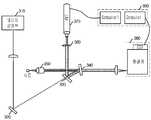
도 1은 본 발명의 실시예 1에 따른 라만 산란광과 동적 광 산란의 동시 검출 장치를 보여주는 도면이다.1 is a view showing an apparatus for simultaneously detecting Raman scattered light and dynamic light scattering according to
도 1을 참조하면, 라만 산란광과 광산란 동시 검출 장치는, 레이저 발생부 (110), 라만 산란 검출부 (120), 동적 광산란 검출부(131~133), 분광계 (140), 컴퓨터 (150)을 포함하여 구성된다.Referring to FIG. 1, an apparatus for detecting Raman scattered light and light scattering simultaneously includes a
레이저 발생부 (110)은 이에 제한되지는 않지만, 입사광으로써 514.5nm Ar-ion의 레이저빔을 발생시킨다. 발생된 입사광은 집광렌즈 112를 통과해서 평면거울 (111)에서 반사되어 라만 산란 검출부 (120)으로 입사된다.Although not limited thereto, the
상기 라만 산란 검출부 (120)은 상술한 노치필터 (121), 대물 렌즈 (123), 제1 수집렌즈 (125)을 포함하여 구성된다. 상기 평면거울 (111)로부터 반사되어 입사된 입사광은 상기 노치필터 (121)에 의해 촛점을 맞추기 위해 사용되는 상기 대물렌즈 (123)으로 반사되어 시료로 입사된다. 상기 시료에 레이저 빔이 입사되면 입사광은 산란되고, 이 중 일부는 다시 상기 대물 렌즈 (123)을 통해 수집된다(180° 검출구조). 상기 대물렌즈 (123)을 통해 수집된 산란광 중 탄성광은 상기 노치필터 (121)에 의해 필터링 되고, 라만 산란광은 통과되어 제 1 수집렌즈 (125)를 통해 분광계(spectrometer) (140)으로 전달된다. 상기 분광계 (140)은 라만 산란광의 스펙트럼을 검출하고, 검출된 스펙트럼은 분광계 (140)에 구비된 CCD 검출기(예를 들어, Ando, DU401)에 의해 기록된다.The Raman
상기 동적 광산란 검출부는 전형적인 구조의 동적 광산란 검출수단과 같이, 입사광의 입사각에 대해 90° 구조로 배치되며, 제 2수집렌즈 (131), 아이리스 (132) 및 PMT 검출기 (133)을 포함하여 구성된다. 시료에 입사되어 산란된 빛은 상기 제2수집렌즈 (131)에 의해 수집되고, 이 중 일부는 아이리스 (132)로 걸러내어 수집된 빛의 수집 각을 가능한 줄이게 된다. 상기 아이리스 (132)를 통과한 빛은 PMT 검출기 (133)으로 전달된다. 상기 PMT 검출기 (133)는 컴퓨터 ((150)에 구비되는 자기상관부(autocorrelator board)(예를 들어, Brookhaven Instruments Corporation, BI-9000AT)와 접속되어 있다.The dynamic light scattering detection unit is arranged in a 90 ° structure with respect to the incident angle of the incident light, like the dynamic light scattering detection means of a typical structure, and comprises a second collecting
상술한 실시예 1에서, 입사광의 포커싱 및 산란광의 수집이 하나의 관찰렌즈 (123)에 의해 수행되는 180° 검출구조에 의해, 광학적인 조정은 매우 용이하다. 또한, 본 실시예는 180° 검출구조의 라만 산란 검출수단과는 독립적으로, 90° 검출구조에 의한 탄성 산란 검출 수단으로 구성되어 광학적 구성이 용이하고 독립된 라만 산란 측정 장비와 동적 광산란 측정 장비의 장점을 그대로 가진다.In
<실시예 2 : 90° 구조의 라만 산란 측정 및 90° 구조의 광산란 측정>Example 2 Raman Scattering Measurement of 90 ° Structure and Light Scattering Measurement of 90 ° Structure
이 방법은 90° 구조로 집광된 산란광을 노치필터를 이용하여 라만 산란광과 탄성 산란광으로 분리하여 동시에 라만 산란과 광산란을 측정하는 구조이다. 90°의 집광 구조는 라만 산란 및 동적 광산란 측정에서 가장 보편적으로 사용되는 구조로써 이 구조의 기존 광학적 구성의 장점을 그대로 살릴 수 있다. 광산란 검출에 있어서 집광각은 필요에 따라 아이리스 조절을 통해 작은 각으로 조절가능하다.In this method, the scattered light condensed in a 90 ° structure is separated into Raman scattered light and elastic scattered light using a notch filter to simultaneously measure Raman scattering and light scattering. The 90 ° condensing structure is the most commonly used structure for Raman scattering and dynamic light scattering measurements, taking advantage of the existing optical construction of the structure. In light scattering detection, the focusing angle can be adjusted to a small angle through iris adjustment as necessary.
도 2는 본 발명의 실시예 2에 따른 라만 산란광과 동적 광산란의 동시 검출 장치를 보여주는 도면이다.FIG. 2 is a view showing an apparatus for simultaneously detecting Raman scattered light and dynamic light scattering according to Embodiment 2 of the present invention.
도 2를 참조하면, 본 실시예에 따른 라만 산란광과 광산란의 동시 검출 장치는, 라만 산란 검출 수단 및 광산란 검출 수단이 모두 90° 검출구조임을 알 수 있다. 본 실시예에 따른 구조는, 집광 렌즈에 의해 입사광의 응집된 영역과 대물렌즈 (220)에 의해 신호가 수집되는 영역이 서로 수직이기 때문에 라만 산란광 수집 효율이 실시예1의 구조에 비하여 낮을 수 있다. 그러나 입사광의 진행 방향을 따라 발생하는 광학 요소들에 의한 산란 및 반사에 의한 노이즈(noise)가 상대적으로 적은 장점이 있다. 동적 광산란 측정은 전형적인 직각 구조검출이 가능하며, 산란광 수집각 역시 PMT 검출기 (260)의 전단에 구비되는 아이리스 (250)의 조정에 따라 결정된다.Referring to FIG. 2, it can be seen that the Raman scattered light and the light scattering detection apparatus according to the present embodiment have a 90 ° detection structure for both the Raman scattering detection means and the light scattering detection means. In the structure according to the present exemplary embodiment, the Raman scattered light collection efficiency may be lower than that of the first embodiment because the aggregated area of the incident light by the condenser lens and the area where the signal is collected by the
도 2에 도시된 실시예에서, 레이저 발생부 (210)에 의해 발생된 레이저 빔은 집광렌즈 (211)을 통과해서 시료에 입사되고, 대물렌즈 (220)을 통해 수집된다. 수집된 빛은 노치필터 (230)에서 라만 산란광만이 통과되고, 그 외 영역의 산란광은 평면거울 (240)으로 반사된다. 평면거울 (240)에서 반사된 빛은 아이리스 (250)을 거쳐 PMT 검출부 (260)으로 전달된다. 도 2에서, 빛의 전달과정 외에 PMT 검출부 (260), 수집렌즈 (270), 분광계 (280), 컴퓨터 (290)의 동작 및 기능은 도 1에 도시된 실시예와 동일하므로 상세한 설명을 생략한다.In the embodiment shown in FIG. 2, the laser beam generated by the
<실시예 3 : 180° 구조의 라만 산란 측정 및 180° 구조의 광산란 측정>Example 3 Raman Scattering Measurement of 180 ° Structure and Light Scattering Measurement of 180 ° Structure
이 방법은 180° 구조로 집광된 산란광을 노치필터를 이용하여 라만 산란광과 탄성 산란광으로 분리하여 동시에 라만 산란과 광산란을 측정하는 구조이다. 180°의 집광 구조의 구현을 위하여 빔 스플릿터(beam splitter)가 필요하다. 광산란 검출에 있어서 집광각은 필요에 따라 아이리스 조절을 통해 작은 각으로 조절가능하다. 180° 방향의 산란광이 상대적으로 집광각에 대한 자기상관함수의 변화폭이 작아 상대적으로 큰 집광각을 사용할 수 있지만 이 방향의 산란 세기 또한 상대적으로 작다.In this method, the scattered light condensed in 180 ° structure is separated into Raman scattered light and elastic scattered light using a notch filter and simultaneously measured Raman scattered light and scattered light. A beam splitter is required to implement a 180 ° light collecting structure. In light scattering detection, the focusing angle can be adjusted to a small angle through iris adjustment as necessary. Although the scattered light in the 180 ° direction has a relatively small change in autocorrelation function with respect to the focused angle, a relatively large focused angle can be used, but the scattered intensity in this direction is also relatively small.
도 3은 본 발명의 실시예 3에 따른 라만 산란광과 광산란의 동시 검출 장치를 보여주는 도면이다.FIG. 3 is a view showing an apparatus for simultaneously detecting Raman scattered light and light scattering according to Embodiment 3 of the present invention.
도 3을 참조하면, 본 실시예는 라만 산란 검출 및 동적 광산란 검출을 위한 검출장치의 배치가 180° 검출구조임을 알 수 있다. 본 실시예에서, 라만 산란광과 탄성 산란광은 노치필터 (340)에 의해 분리되고 탄성광은 빔스플릿터(beam splitter) (330)에 의해 PMT 검출기 (370)으로 전달된다.Referring to FIG. 3, it can be seen that the present embodiment has a 180 ° detection structure in which a detection device for Raman scattering detection and dynamic light scattering detection is disposed. In this embodiment, the Raman scattered light and the elastic scattered light are separated by the
도 3의 실시예에서, 레이저 발생부 (310)에서 발생된 레이저 빔은 평면거울 (320)에서 반사되어 빔 스플릿터 (330)에 전달된다. 상기 빔 스플릿터 (330)은 산란광을 PMT 검출부 (370)으로 전달하기 위한 구성으로, 50:50의 비율로 입사 및 반사 특성을 갖는다. 따라서, 상기 빔 스플릿터 (330)을 통과한 빛은 노치필터 (340)에서 전반사 되어 대물렌즈 (350)을 통해 시료에 입사된다. 시료에서 산란된 빛은 다시 상기 대물렌즈 (350)에서 수집되어 노치필터 (340)으로 전달되고, 노치 필터 (340)은 라만 산란광만을 통과시켜 분광계 (380)으로 전달되도록 한다. 노치 필터 (340)에서 반사된 산란광은 다시 빔 스플릿터 (330) 및 아이리스 (360)을 거쳐 PMT 검출부 (370)으로 전달된다. 이와 같은 구조에 따라, 대물렌즈에 의한 광 수집각은 커지게 되나, 산란광 검출을 위한 유효한 수집각은 상기 PMT 검출부 (370) 전단에 구비되는 상기 아이리스 (360)의 홀 조정에 따라 조정될 수 있다. 도 3에서, 빛의 전달과정 외에 PMT 검출부 (370), 분광계 (380), 컴퓨터 (390)의 동작 및 기능은 역시 도 1에 도시된 실시예와 동일하므로 상세한 설명을 생략한다.In the example of FIG. 3, the laser beam generated by the
본 실시예에서는, 도 1의 경우와 마찬가지로 역시 산란광의 수집 및 입사가 동일한 대물렌즈에 의해 촛점이 맞추어 지기 때문에 산란광 수집에 매우 효율적이다. 또한 라만 산란과 광산란 동시 측정을 위한 광학적 구조가 매우 간단하고 대물렌즈를 이용한 180° 구조의 집광을 하므로 집광 효율이 매우 높다. 이 같은 집광 효율은, 실시예 3에서 50:50 비율의 입사 반사 특성을 갖는 빔 스플릿터로 인한 빛의 손실을 충분히 극복할 수 있다. In this embodiment, as in the case of Fig. 1, the scattered light collection and incidence are also very efficient for scattered light collection because the same objective lens is focused. In addition, the optical structure for the simultaneous measurement of Raman scattering and light scattering is very simple, and the light condensing efficiency is very high because it collects the 180 ° structure using the objective lens. Such light collection efficiency can sufficiently overcome the loss of light due to the beam splitter having the incident reflection characteristic of the 50:50 ratio in the third embodiment.
<은 나노입자의 응집 정도에 따른 표면증강 라만산란의 세기 변화 측정결과><Measurement result of intensity change of surface-enhanced Raman scattering according to aggregation degree of silver nanoparticles>
특수한 구조의 금속 나노구조물의 표면에서 라만 산란이 평균적으로 106배 이상 증가한다는 표면증강 라만산란 (Surface-Enhanced Raman Scattering, 이하 SERS 라 명함) 현상은 대략 30년 전부터 잘 알려져 있다. 본 측정에서는 용액상의 은 나노입자를 이용하여, 이들이 서로 엉김에 따라서 그 크기의 변화와 이로 인한 SERS 최근 10여 년간 나노 과학기술의 발전과 더불어 금속 나노구조물을 예측한대로 제작할 수 있고 관찰할 수 있게 되면서 이 분야에 대한 새로운 현상이 많이 밝혀졌다. 본 특허에서는 일반적으로 제어 및 관찰이 어려운 용액상의 은 나노입자를 이용하여, 이들이 서로 엉김에 따라서 그 크기의 변화와 이로 인한 SERS 세기에 관련된 연구를 수행하였다.Surface enhanced Raman scattering is that the Raman scattered on average more than 106 times on the surface of the metal nanostructure of particular structure (Surface-Enhanced Raman Scattering, SERS hereinafter referred card) phenomenon is known about 30 years. In this measurement, using silver nanoparticles in solution, the size changes as they are entangled with each other and SERS resulting in the development of nanotechnology with the development of nanotechnology over the past decade, and as a result, metal nanostructures can be manufactured and observed as expected. Many new phenomena have been identified in this area. In the present patent, using silver nanoparticles in solution phase, which are generally difficult to control and observe, studies related to changes in size and thus SERS strength as they are entangled with each other are performed.
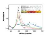
도 4는 수용액상의 은 나노입자를 폴리(4-비닐피리딘)(Poly(4-vinyl pyridine), MW 60000, Aldrich) 을 처리하여 폴리(4-비닐피리딘)의 농도에 따라 은 나노입자의 엉김이 변하고 이로 인해서 관찰되는 표면 플라즈몬 흡수의 변화를 보여준다. 도 4에서 A, B, C, D, E, F, 와 G는 P4VP 의 농도가 각각 0, 5×10⁻⁶, 1×10⁻⁵, 5×10⁻⁵, 1×10⁻⁴, 5×10⁻⁴, 와 1×10⁻³ g/dL 인 경우에 해당한다. 특징적인 변화로 A 에서 D 로 가면서 은 나노입자들간의 응집에 의한 새로운 흡수 밴드가 390 nm 보다 장파장 쪽으로 생기고 이 밴드가 점차 적색이동을 하는 것을 관찰할 수 있다. 그러나 D 에서 G 로 가면서 이 새로운 밴드가 다시 청색이동을 하고 궁극적으로는 390 nm 근처에서 나타나는 밴드와 합쳐지는 것을 관찰할 수 있다. 이 같은 변화는 폴리(4-비닐피리딘)의 농도가 어느 정도 이상 높아지면 은 나노입자들간의 상호작용이 오히려 줄어는 것을 나타내는데 이는 폴리(4-비닐피리딘)의 농도가 높아지면서 은 나노입자들 간의 거리가 멀어진 것을 반영한다.FIG. 4 shows that silver nanoparticles are entangled according to the concentration of poly (4-vinylpyridine) by treating poly (4-vinylpyridine) (MW 60000, Aldrich) with silver nanoparticles in aqueous solution. Changes in surface plasmon absorption observed. In FIG. 4, A, B, C, D, E, F, and G have P4VP concentrations of 0, 5 × 10⁻⁶ , 1 × 10⁻⁵ , 5 × 10⁻⁵ , 1 × 10⁻⁴ , 5, respectively. Corresponds to the case of × 10−4 , and 1 × 10⁻³ g / dL. As a characteristic change, from A to D, a new absorption band due to the aggregation of silver nanoparticles is formed in the longer wavelength than 390 nm, and the band gradually red shifts. But as we go from D to G, we can see that this new band moves blue again and eventually merges with the band appearing near 390 nm. This change indicates that the interaction between silver nanoparticles decreases when the concentration of poly (4-vinylpyridine) is increased to some extent. This is because the concentration of poly (4-vinylpyridine) increases. Reflect the distance.
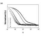
도 5와 도 6은 폴리(4-비닐피리딘)에 의한 은 나노입자들 간의 응집 정도 및 크기 변화와 이에 따른 SERS 변화를 관찰하기 위하여 동적 광산란과 라만 산란을 동시에 측정한 결과를 보여준다. 도 5의 (a)는 검출된 산란광으로부터 얻은 상관함수를 나타내고 (b)는 이를 분석하여 얻은 나노입자의 크기 분포를 나타낸다. 이 그림에서 나타나듯이 폴리(4-비닐피리딘)의 농도가 증가하면서 급격하게 크기가 증가하다가 다시 D 에서 G로 가면서 크기가 줄어드는 것을 볼 수 있다. 이 변화는 도 4에서 관찰된 경향과 일치한다. 특히, C 에서 D 로 가면서 크기가 급격히 커진 것을 볼 수 있다. 이는 폴리(4-비닐피리딘)가 은 나노입자 표면에 흡착하면서 표면의 전하를 중성화시켜 은 나노입자가 불안해지고 이들간의 응집이 유도되었기 때문이다.5 and 6 show the results of simultaneous measurement of dynamic light scattering and Raman scattering in order to observe the degree of aggregation and size change of the silver nanoparticles by poly (4-vinylpyridine) and the resulting SERS change. Figure 5 (a) shows the correlation function obtained from the detected scattered light and (b) shows the size distribution of the nanoparticles obtained by analyzing it. As shown in the figure, the size increases rapidly with increasing poly (4-vinylpyridine) concentration and then decreases as D goes to G. This change is consistent with the trend observed in FIG. 4. In particular, it can be seen that the size rapidly increased from C to D. This is because the poly (4-vinylpyridine) is adsorbed on the surface of the silver nanoparticles to neutralize the charge on the surface, causing the silver nanoparticles to become unstable and induce aggregation among them.
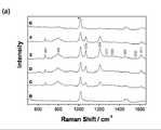
도 6의 (a) 는 광산란과 동시에 측정한 은 표면에 흡착된 폴리(4-비닐피리딘)의 SERS 스펙트럼이고 (b) 는 1019 cm-1 라만 밴드를 용매에서 기인한 밴드로 나누고 폴리(4-비닐피리딘)의 농도로 나누어서 표준화한 SERS 신호의 세기를 나타낸다. 시료 A는 P4VP를 넣지 않은 시료이므로 여기서는 생략한다. 도 6(b)는 도 6(a)와 함께 얻은 라만 산란 스펙트럼으로써 크기가 변하면서 라만산란 세기가 변하는 것을 나타낸다. 그림 (b) 에서도 광산란의 결과와 같이 SERS 신호의 세기가 증가하다가 감소하는데, 이는 은 나노입자가 많이 뭉칠수록 SERS 신호의 크기가 커지는 것이 아니고 적절한 정도의 뭉침이 요구된다는 것을 말해준다.(A) is SERS spectrum of poly (4-vinylpyridine) adsorbed on the surface of silver measured simultaneously with light scattering, and (b) divides the 1019 cm-1 Raman band by the band originating from the solvent and Divided by the concentration of vinylpyridine) to represent the normalized SERS signal intensity. Sample A is omitted here because it is a sample without P4VP. FIG. 6 (b) shows the Raman scattering intensity as the Raman scattering spectrum obtained with FIG. 6 (a) changes in size. As in the result of light scattering in Fig. (B), the intensity of SERS signal increases and decreases, indicating that the more silver nanoparticles are aggregated, the larger the size of the SERS signal is.
위에서 양호한 실시 예에 근거하여 이 발명을 설명하였지만, 이러한 실시 예는 이 발명을 제한하려는 것이 아니라 예시하려는 것이다. 이 발명이 속하는 분 야의 숙련자에게는 이 발명의 기술사상을 벗어남이 없이 위 실시 예에 대한 다양한 변화나 변경 또는 조절이 가능함이 자명할 것이다. 예를 들어, 본 발명의 실시예에서는 동적 광산란을 중심으로 설명하였으나, 다양한 각도에서 측정되고 자기상관함수를 사용하지 않는 정적 광산란 측정에도 적용될 수 있음은 당업자에게 자명하다.While the invention has been described above based on the preferred embodiments thereof, these embodiments are intended to illustrate rather than limit the invention. It will be apparent to those skilled in the art that various changes, modifications, or adjustments to the above embodiments can be made without departing from the spirit of the invention. For example, although embodiments of the present invention have been described based on dynamic light scattering, it will be apparent to those skilled in the art that the present invention can be applied to static light scattering measurement measured at various angles and not using an autocorrelation function.
그러므로, 이 발명의 보호범위는 첨부된 청구범위 뿐만 아니라, 위와 같은 변화예나 변경예 또는 조절예를 모두 포함하는 것으로 해석되어야 할 것이다.Therefore, the protection scope of the present invention should be construed to include not only the appended claims but also all of the above changes, modifications or adjustments.
이상에서 살펴본 바와 같이, 본 발명은 하나의 시료에 대하여 동시에 라만 산란과 광산란을 측정할 수 있으므로, 나노 크기의 물질의 크기와 그 물질을 구성하는 분자에 대한 정보의 분석이 가능한 이점이 있다. 즉, 나노 물질의 성장 및 변화, 나노 물질과 단백질 간의 결합, 항원-항체 반응 등의 현상에서 물질의 크기 변화와 그에 따른 분자적 환경의 변화를 관찰하는 수단이 된다.As described above, the present invention can measure the Raman scattering and light scattering on one sample at the same time, there is an advantage that can analyze the information on the size of the nano-sized material and the molecules constituting the material. In other words, it is a means of observing the change in the size of the material and the resulting molecular environment in the growth and change of nanomaterials, the binding between the nanomaterial and protein, antigen-antibody reaction.
Claims (8)
Translated fromKoreanPriority Applications (3)
| Application Number | Priority Date | Filing Date | Title |
|---|---|---|---|
| KR1020060090516AKR100817854B1 (en) | 2006-09-19 | 2006-09-19 | Simultaneous Detection of Raman Scattered Light and Light Scattering |
| US12/442,109US8018582B2 (en) | 2006-09-19 | 2007-08-30 | Simultaneous detection apparatus of raman and light scattering |
| PCT/KR2007/004183WO2008035864A1 (en) | 2006-09-19 | 2007-08-30 | A simultaneous detection apparatus of raman and light scattering |
Applications Claiming Priority (1)
| Application Number | Priority Date | Filing Date | Title |
|---|---|---|---|
| KR1020060090516AKR100817854B1 (en) | 2006-09-19 | 2006-09-19 | Simultaneous Detection of Raman Scattered Light and Light Scattering |
Publications (2)
| Publication Number | Publication Date |
|---|---|
| KR20080025845A KR20080025845A (en) | 2008-03-24 |
| KR100817854B1true KR100817854B1 (en) | 2008-03-31 |
Family
ID=39200665
Family Applications (1)
| Application Number | Title | Priority Date | Filing Date |
|---|---|---|---|
| KR1020060090516AExpired - Fee RelatedKR100817854B1 (en) | 2006-09-19 | 2006-09-19 | Simultaneous Detection of Raman Scattered Light and Light Scattering |
Country Status (3)
| Country | Link |
|---|---|
| US (1) | US8018582B2 (en) |
| KR (1) | KR100817854B1 (en) |
| WO (1) | WO2008035864A1 (en) |
Cited By (1)
| Publication number | Priority date | Publication date | Assignee | Title |
|---|---|---|---|---|
| WO2024235929A1 (en) | 2023-05-17 | 2024-11-21 | Universite De Geneve | Particle characterization system |
Families Citing this family (23)
| Publication number | Priority date | Publication date | Assignee | Title |
|---|---|---|---|---|
| US8877507B2 (en) | 2007-04-06 | 2014-11-04 | Qiagen Gaithersburg, Inc. | Ensuring sample adequacy using turbidity light scattering techniques |
| US8355132B2 (en) | 2007-04-06 | 2013-01-15 | Qiagen Gaithersburg, Inc. | Sample adequacy measurement system having a plurality of sample tubes and using turbidity light scattering techniques |
| US8703492B2 (en) | 2007-04-06 | 2014-04-22 | Qiagen Gaithersburg, Inc. | Open platform hybrid manual-automated sample processing system |
| KR101207695B1 (en)* | 2010-08-11 | 2012-12-03 | 서울대학교산학협력단 | Medical imaging method for simultaneous detection of multiplex targets using fluorescent and raman signal and apparatus for simultaneously detecting multiplex targets of fluorescent and raman signal using therof |
| US9833145B2 (en) | 2010-08-11 | 2017-12-05 | Snu R&Db Foundation | Method for simultaneously detecting fluorescence and raman signals for multiple fluorescence and raman signal targets, and medical imaging device for simultaneously detecting multiple targets using the method |
| US9163987B2 (en) | 2010-08-24 | 2015-10-20 | Kla-Tencor Corporation | Defect inspection and photoluminescence measurement system |
| US9816922B2 (en) | 2011-08-19 | 2017-11-14 | Malvern Instruments Limited | Dual-mode characterization of particulates |
| CN103091299B (en) | 2013-01-21 | 2015-01-21 | 北京理工大学 | Laser differential confocal map microimaging imaging method and device |
| CN104458510B (en)* | 2013-07-22 | 2016-08-24 | 南通大学 | Improve detection of particles size and the optical system of shape of detection accuracy |
| CN104390897B (en)* | 2013-07-22 | 2016-08-24 | 南通大学 | Improve detection molecule size and the optical system of shape of beam uniformity |
| CN104390896B (en)* | 2013-07-22 | 2017-01-18 | 南通大学 | Measurement precision improved optical system for detecting size and shape of microparticle |
| CN103364317B (en)* | 2013-07-22 | 2015-06-10 | 南通大学 | Optical system for detecting size and shape of micro-particles |
| CN103940800B (en)* | 2014-03-10 | 2016-08-17 | 北京理工大学 | Confocal laser Brillouin-method for measuring Raman spectrum and device |
| CN103954602B (en)* | 2014-03-10 | 2016-08-17 | 北京理工大学 | Laser dual-axis differential confocal Brillouin-method for measuring Raman spectrum and device |
| CN104677885B (en)* | 2015-03-17 | 2017-09-05 | 北京理工大学 | High spatial resolution laser differential confocal spectroscopy-mass spectrometry microscopic imaging method and device |
| CN104698070B (en)* | 2015-03-17 | 2018-07-20 | 北京理工大学 | High-space resolution confocal laser mass spectrum micro imaging method and device |
| CN105758770A (en)* | 2015-11-03 | 2016-07-13 | 大族激光科技产业集团股份有限公司 | Integrated substance component and granularity analyzing system and method |
| US10365198B2 (en) | 2016-04-21 | 2019-07-30 | Malvern Panalytical Limited | Particle characterization |
| US11326944B2 (en) | 2019-07-12 | 2022-05-10 | Biospex, Inc. | Wearable spectrometer with filtered sensor |
| US11454540B2 (en)* | 2019-07-12 | 2022-09-27 | Biospex, Inc. | Wearable spectroscopy using filtered sensor |
| CN110243799A (en)* | 2019-07-30 | 2019-09-17 | 南昌航空大学 | A method for rapid detection of aflatoxin |
| CN111122540A (en)* | 2019-12-25 | 2020-05-08 | 桂林电子科技大学 | Multifunctional fiber optic probe system based on time-correlated single-photon detection technology |
| CN111161998B (en)* | 2020-02-10 | 2025-06-17 | 浙江迪谱诊断技术有限公司 | A laser coaxial ion excitation device |
Citations (4)
| Publication number | Priority date | Publication date | Assignee | Title |
|---|---|---|---|---|
| JPH09145619A (en)* | 1995-09-20 | 1997-06-06 | Kdk Corp | Method and instrument for spectroscopic measurement of scattered light and so on |
| JPH09243569A (en)* | 1996-03-06 | 1997-09-19 | Toshiba Corp | Semiconductor substrate evaluation apparatus and evaluation method |
| KR19990071667A (en)* | 1995-11-27 | 1999-09-27 | 케이스 웨인 에이 | Surface Characterization Device and Method |
| KR20030041147A (en)* | 2000-10-03 | 2003-05-23 | 액센트 옵티칼 테크놀로지스 인코포레이티드 | Differential numerical aperture methods and device |
Family Cites Families (6)
| Publication number | Priority date | Publication date | Assignee | Title |
|---|---|---|---|---|
| US3850525A (en)* | 1973-07-09 | 1974-11-26 | Beckman Instruments Inc | Simultaneous multiple measurements in laser photometers |
| US4071298A (en)* | 1974-06-27 | 1978-01-31 | Stanford Research Institute | Laser Raman/fluorescent device for analyzing airborne particles |
| US5870188A (en)* | 1995-09-20 | 1999-02-09 | Kyoto Dei-Ichi, Kagaku Co. Ltd. | Measuring method and measuring apparatus by light scattering |
| KR100273711B1 (en) | 1998-04-17 | 2001-03-02 | 서정쌍 | Signal collecting apparatus for raman spectrometer |
| US6256097B1 (en)* | 1999-01-08 | 2001-07-03 | Rudolph Technologies, Inc. | Ellipsometer and ellipsometry method |
| KR20040053290A (en)* | 2001-11-09 | 2004-06-23 | 엑손모빌 케미칼 패턴츠 인코포레이티드 | On-line measurement and control of polymer properties by raman spectroscopy |
- 2006
- 2006-09-19KRKR1020060090516Apatent/KR100817854B1/ennot_activeExpired - Fee Related
- 2007
- 2007-08-30USUS12/442,109patent/US8018582B2/enactiveActive
- 2007-08-30WOPCT/KR2007/004183patent/WO2008035864A1/enactiveApplication Filing
Patent Citations (4)
| Publication number | Priority date | Publication date | Assignee | Title |
|---|---|---|---|---|
| JPH09145619A (en)* | 1995-09-20 | 1997-06-06 | Kdk Corp | Method and instrument for spectroscopic measurement of scattered light and so on |
| KR19990071667A (en)* | 1995-11-27 | 1999-09-27 | 케이스 웨인 에이 | Surface Characterization Device and Method |
| JPH09243569A (en)* | 1996-03-06 | 1997-09-19 | Toshiba Corp | Semiconductor substrate evaluation apparatus and evaluation method |
| KR20030041147A (en)* | 2000-10-03 | 2003-05-23 | 액센트 옵티칼 테크놀로지스 인코포레이티드 | Differential numerical aperture methods and device |
Cited By (1)
| Publication number | Priority date | Publication date | Assignee | Title |
|---|---|---|---|---|
| WO2024235929A1 (en) | 2023-05-17 | 2024-11-21 | Universite De Geneve | Particle characterization system |
Also Published As
| Publication number | Publication date |
|---|---|
| KR20080025845A (en) | 2008-03-24 |
| WO2008035864A1 (en) | 2008-03-27 |
| US8018582B2 (en) | 2011-09-13 |
| US20100020312A1 (en) | 2010-01-28 |
Similar Documents
| Publication | Publication Date | Title |
|---|---|---|
| KR100817854B1 (en) | Simultaneous Detection of Raman Scattered Light and Light Scattering | |
| JP7698765B2 (en) | PARTICLE DETECTION SYSTEM AND METHOD FOR ON-AXIS PARTICLE DETECTION AND/OR DIFFERENTIAL DETECTION - Patent application | |
| JP7726920B2 (en) | PARTICLE DETECTION SYSTEM AND METHOD FOR PARTICLE DETECTION - Patent application | |
| JP5325679B2 (en) | Dynamic light scattering measuring apparatus and light scattering intensity measuring method using low coherence light source | |
| JP5259736B2 (en) | Particle measuring apparatus and particle characteristic measuring method | |
| US7876450B2 (en) | Common-path interferometer rendering amplitude and phase of scattered light | |
| US20090323061A1 (en) | Multi-color hetereodyne interferometric apparatus and method for sizing nanoparticles | |
| JP5381741B2 (en) | Optical measuring apparatus and optical measuring method | |
| CN103604502B (en) | A kind of Raman spectrometer detecting high scattering material | |
| EP2257789B1 (en) | Biological and chemical microscopic targeting | |
| US9170203B2 (en) | Enhancement of raman scattering | |
| JP4909254B2 (en) | Airborne particulate matter measurement device | |
| CN106896095B (en) | Composite Surface Plasmon Resonance and Surface Enhanced Raman Microscopic Imaging Technology | |
| CA2604661A1 (en) | Method and applications to enhance and image optical signals from biological objects | |
| JP2014062822A (en) | Fine particle analyzer and fine particle analyzing method | |
| JP2021517963A (en) | Particle sizing improved by light diffraction | |
| KR101632672B1 (en) | Confocal spectrogram microscope | |
| JP5662742B2 (en) | Particle size measuring apparatus and particle size measuring method | |
| JP2013152192A (en) | Organic compound analyzer and organic compound analysis method | |
| CN101581655A (en) | Counter for metal nano particles in solution | |
| CN107727614B (en) | Space-time resolution spectral imaging system | |
| CN110823786A (en) | Device and method for detecting tiny particles in liquid | |
| CN207689375U (en) | Lower wave number Raman Measurement system | |
| US7365835B2 (en) | Dark-field laser-scattering microscope for analyzing single macromolecules | |
| JP2016142617A (en) | Electric field enhancement element, analyzer, and electronic apparatus |
Legal Events
| Date | Code | Title | Description |
|---|---|---|---|
| A201 | Request for examination | ||
| PA0109 | Patent application | St.27 status event code:A-0-1-A10-A12-nap-PA0109 | |
| PA0201 | Request for examination | St.27 status event code:A-1-2-D10-D11-exm-PA0201 | |
| D13-X000 | Search requested | St.27 status event code:A-1-2-D10-D13-srh-X000 | |
| D14-X000 | Search report completed | St.27 status event code:A-1-2-D10-D14-srh-X000 | |
| E902 | Notification of reason for refusal | ||
| PE0902 | Notice of grounds for rejection | St.27 status event code:A-1-2-D10-D21-exm-PE0902 | |
| P11-X000 | Amendment of application requested | St.27 status event code:A-2-2-P10-P11-nap-X000 | |
| P13-X000 | Application amended | St.27 status event code:A-2-2-P10-P13-nap-X000 | |
| R18-X000 | Changes to party contact information recorded | St.27 status event code:A-3-3-R10-R18-oth-X000 | |
| E701 | Decision to grant or registration of patent right | ||
| PE0701 | Decision of registration | St.27 status event code:A-1-2-D10-D22-exm-PE0701 | |
| GRNT | Written decision to grant | ||
| PG1501 | Laying open of application | St.27 status event code:A-1-1-Q10-Q12-nap-PG1501 | |
| PR0701 | Registration of establishment | St.27 status event code:A-2-4-F10-F11-exm-PR0701 | |
| PR1002 | Payment of registration fee | St.27 status event code:A-2-2-U10-U11-oth-PR1002 Fee payment year number:1 | |
| PG1601 | Publication of registration | St.27 status event code:A-4-4-Q10-Q13-nap-PG1601 | |
| PN2301 | Change of applicant | St.27 status event code:A-5-5-R10-R11-asn-PN2301 | |
| PN2301 | Change of applicant | St.27 status event code:A-5-5-R10-R14-asn-PN2301 | |
| PR1001 | Payment of annual fee | St.27 status event code:A-4-4-U10-U11-oth-PR1001 Fee payment year number:4 | |
| PR1001 | Payment of annual fee | St.27 status event code:A-4-4-U10-U11-oth-PR1001 Fee payment year number:5 | |
| FPAY | Annual fee payment | Payment date:20130325 Year of fee payment:6 | |
| PR1001 | Payment of annual fee | St.27 status event code:A-4-4-U10-U11-oth-PR1001 Fee payment year number:6 | |
| FPAY | Annual fee payment | Payment date:20140304 Year of fee payment:7 | |
| PR1001 | Payment of annual fee | St.27 status event code:A-4-4-U10-U11-oth-PR1001 Fee payment year number:7 | |
| R18-X000 | Changes to party contact information recorded | St.27 status event code:A-5-5-R10-R18-oth-X000 | |
| PN2301 | Change of applicant | St.27 status event code:A-5-5-R10-R11-asn-PN2301 | |
| PN2301 | Change of applicant | St.27 status event code:A-5-5-R10-R14-asn-PN2301 | |
| PN2301 | Change of applicant | St.27 status event code:A-5-5-R10-R11-asn-PN2301 | |
| PN2301 | Change of applicant | St.27 status event code:A-5-5-R10-R14-asn-PN2301 | |
| R18-X000 | Changes to party contact information recorded | St.27 status event code:A-5-5-R10-R18-oth-X000 | |
| LAPS | Lapse due to unpaid annual fee | ||
| PC1903 | Unpaid annual fee | St.27 status event code:A-4-4-U10-U13-oth-PC1903 Not in force date:20150325 Payment event data comment text:Termination Category : DEFAULT_OF_REGISTRATION_FEE | |
| PC1903 | Unpaid annual fee | St.27 status event code:N-4-6-H10-H13-oth-PC1903 Ip right cessation event data comment text:Termination Category : DEFAULT_OF_REGISTRATION_FEE Not in force date:20150325 |