KR100817789B1 - PLC speaker system - Google Patents
PLC speaker systemDownload PDFInfo
- Publication number
- KR100817789B1 KR100817789B1KR1020060073631AKR20060073631AKR100817789B1KR 100817789 B1KR100817789 B1KR 100817789B1KR 1020060073631 AKR1020060073631 AKR 1020060073631AKR 20060073631 AKR20060073631 AKR 20060073631AKR 100817789 B1KR100817789 B1KR 100817789B1
- Authority
- KR
- South Korea
- Prior art keywords
- signal
- sound
- speaker
- sound signal
- unit
- Prior art date
- Legal status (The legal status is an assumption and is not a legal conclusion. Google has not performed a legal analysis and makes no representation as to the accuracy of the status listed.)
- Active
Links
- 230000005236sound signalEffects0.000claimsabstractdescription139
- 230000005540biological transmissionEffects0.000claimsabstractdescription80
- 230000006854communicationEffects0.000claimsabstractdescription37
- 238000004891communicationMethods0.000claimsabstractdescription37
- 238000012545processingMethods0.000claimsabstractdescription18
- 238000000034methodMethods0.000claimsdescription23
- 238000006243chemical reactionMethods0.000claimsdescription13
- 239000000284extractSubstances0.000claimsdescription5
- 238000010276constructionMethods0.000abstractdescription2
- 238000005516engineering processMethods0.000description2
- 230000007175bidirectional communicationEffects0.000description1
- 238000011161developmentMethods0.000description1
- 230000000694effectsEffects0.000description1
- 230000005284excitationEffects0.000description1
- 238000009434installationMethods0.000description1
- 238000012986modificationMethods0.000description1
- 230000004048modificationEffects0.000description1
- 230000000644propagated effectEffects0.000description1
- 230000008054signal transmissionEffects0.000description1
- 238000006467substitution reactionMethods0.000description1
Images


Classifications
- H—ELECTRICITY
- H04—ELECTRIC COMMUNICATION TECHNIQUE
- H04R—LOUDSPEAKERS, MICROPHONES, GRAMOPHONE PICK-UPS OR LIKE ACOUSTIC ELECTROMECHANICAL TRANSDUCERS; DEAF-AID SETS; PUBLIC ADDRESS SYSTEMS
- H04R3/00—Circuits for transducers, loudspeakers or microphones
- H—ELECTRICITY
- H04—ELECTRIC COMMUNICATION TECHNIQUE
- H04H—BROADCAST COMMUNICATION
- H04H20/00—Arrangements for broadcast or for distribution combined with broadcast
- H04H20/53—Arrangements specially adapted for specific applications, e.g. for traffic information or for mobile receivers
- H04H20/61—Arrangements specially adapted for specific applications, e.g. for traffic information or for mobile receivers for local area broadcast, e.g. instore broadcast
- H—ELECTRICITY
- H04—ELECTRIC COMMUNICATION TECHNIQUE
- H04R—LOUDSPEAKERS, MICROPHONES, GRAMOPHONE PICK-UPS OR LIKE ACOUSTIC ELECTROMECHANICAL TRANSDUCERS; DEAF-AID SETS; PUBLIC ADDRESS SYSTEMS
- H04R1/00—Details of transducers, loudspeakers or microphones
- H04R1/06—Arranging circuit leads; Relieving strain on circuit leads
- H—ELECTRICITY
- H05—ELECTRIC TECHNIQUES NOT OTHERWISE PROVIDED FOR
- H05K—PRINTED CIRCUITS; CASINGS OR CONSTRUCTIONAL DETAILS OF ELECTRIC APPARATUS; MANUFACTURE OF ASSEMBLAGES OF ELECTRICAL COMPONENTS
- H05K7/00—Constructional details common to different types of electric apparatus
- H05K7/14—Mounting supporting structure in casing or on frame or rack
- H05K7/1462—Mounting supporting structure in casing or on frame or rack for programmable logic controllers [PLC] for automation or industrial process control
- Y—GENERAL TAGGING OF NEW TECHNOLOGICAL DEVELOPMENTS; GENERAL TAGGING OF CROSS-SECTIONAL TECHNOLOGIES SPANNING OVER SEVERAL SECTIONS OF THE IPC; TECHNICAL SUBJECTS COVERED BY FORMER USPC CROSS-REFERENCE ART COLLECTIONS [XRACs] AND DIGESTS
- Y02—TECHNOLOGIES OR APPLICATIONS FOR MITIGATION OR ADAPTATION AGAINST CLIMATE CHANGE
- Y02D—CLIMATE CHANGE MITIGATION TECHNOLOGIES IN INFORMATION AND COMMUNICATION TECHNOLOGIES [ICT], I.E. INFORMATION AND COMMUNICATION TECHNOLOGIES AIMING AT THE REDUCTION OF THEIR OWN ENERGY USE
- Y02D30/00—Reducing energy consumption in communication networks
- Y02D30/70—Reducing energy consumption in communication networks in wireless communication networks
Landscapes
- Engineering & Computer Science (AREA)
- Signal Processing (AREA)
- Physics & Mathematics (AREA)
- Acoustics & Sound (AREA)
- Automation & Control Theory (AREA)
- Microelectronics & Electronic Packaging (AREA)
- Cable Transmission Systems, Equalization Of Radio And Reduction Of Echo (AREA)
Abstract
Translated fromKoreanDescription
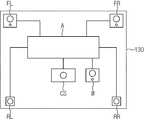
Translated fromKorean도 1은 종래 기술로서 복수개의 스피커 시스템을 구현한 실시예를 나타낸다.1 illustrates an embodiment in which a plurality of speaker systems are implemented as a prior art.
도 2는 종래 기술로서 멀티채널 스피커 시스템을 구현한 실시예를 나타낸다.2 illustrates an embodiment in which a multichannel speaker system is implemented as a prior art.
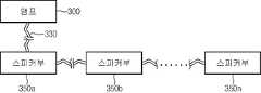
도 3은 종래 기술로서 무선 음향 시스템을 구현한 실시예를 나타낸다.3 shows an embodiment of implementing a wireless acoustic system as a prior art.
도 4는 본 발명에 따른 PLC 스피커 시스템의 실시예를 개략적으로 도시한다.4 schematically shows an embodiment of a PLC speaker system according to the invention.
도 5는 본 발명에 따른 PLC 스피커 시스템에 있어서, 복수개의 스피커부가 형성된 실시예를 개략적으로 도시한다.5 schematically shows an embodiment in which a plurality of speaker units are formed in a PLC speaker system according to the present invention.
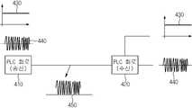
도 6a 및 도 6b는 본 발명에 따른 PLC 스피커 시스템에 있어서, 전력과 음향신호를 전송하는 방법을 개략적으로 도시한다.6A and 6B schematically illustrate a method of transmitting power and sound signals in a PLC speaker system according to the present invention.
도 7은 본 발명에 따른 PLC 스피커 시스템에 있어서, 직류 전력을 제공하는 전송선로를 이용하여 음향신호를 전달하는 실시예를 개략적으로 나타낸다.FIG. 7 schematically illustrates an embodiment in which a sound signal is transmitted using a transmission line for providing direct current power in a PLC speaker system according to the present invention.
도 8 및 도 9는 본 발명에 따른 PLC 스피커 시스템에 있어서, 멀티채널 스피커 시스템을 구현한 실시예를 개략적으로 도시한다.8 and 9 schematically show an embodiment of implementing a multi-channel speaker system in the PLC speaker system according to the present invention.
도 10은 본 발명에 따른 PLC 스피커 시스템에 있어서, 방송 시스템을 구현한 실시예를 개략적으로 도시한다.10 schematically illustrates an embodiment of implementing a broadcasting system in a PLC speaker system according to the present invention.
도 11은 본 발명에 따른 PLC 스피커 시스템에 있어서, 스피커폰에 대한 실시예를 개략적으로 도시한다.11 schematically shows an embodiment of a speakerphone in a PLC speaker system according to the present invention.
도 12는 본 발명에 따른 PLC 스피커 시스템에 있어서, 복수개의 스피커폰이 형성된 실시예를 개략적으로 도시한다.12 schematically illustrates an embodiment in which a plurality of speakerphones are formed in a PLC speaker system according to the present invention.
< 도면의 주요 부분에 대한 부호의 설명 ><Description of Symbols for Main Parts of Drawings>
300 : 음향장치부, 330 : 전송선로, 350,350a,350b,…,350n : 스피커부300: sound device, 330: transmission line, 350, 350a, 350b, ... , 350n: Speaker part
303, 410 : 송신 PLC 회로, 351, 420 : 수신 PLC 회로,303, 410: transmit PLC circuit, 351, 420: receive PLC circuit,
430 : 직류전원파, 440 : 음향신호파, 450 : 직류전원과 음향신호 중첩파430: DC power wave, 440: acoustic signal wave, 450: DC power and acoustic signal wave
501 : 콘센트/통신포트,501: outlet / communication port,
A : 앰프, CS, W, FL, FR, RL, RR : 5.1채널 스피커A: Amplifier, CS, W, FL, FR, RL, RR: 5.1-channel speaker
700, 700a, 700b, 700c,… ,700n : 스피커폰부700, 700a, 700b, 700c,... , 700n: Speakerphone part
본 발명은 PLC(Power Line Communication) 스피커 시스템에 관한 것으로, 보다 상세하게는 멀티채널을 위한 다수의 스피커 또는 건물 내에 방송시스템을 위한 다수의 스피커 및 스피커폰에 대한 음향 신호를 전력과 함께 전송선로를 이용하여 전송하는 스피커 시스템에 관한 것이다.The present invention relates to a power line communication (PLC) speaker system, and more particularly, to a plurality of speakers for multichannel or a plurality of speakers and speakerphones for a broadcasting system in a building using a transmission line together with power. It relates to a speaker system for transmitting.
일반적인 아파트나 학교 등의 건물 내에서 안내방송 등을 위한 스피커 시스 템을 구축하는 경우 각각의 스피커마다 개별적인 배선을 하여 방송실로 결선하는 방법을 사용하여 왔다. 이로 인해 배선 등의 설비에 있어서 과다한 비용, 배선 배치의 복잡성 등이 문제가 되어 이에 대한 개선이 절실히 요구되고 있다.In the case of building a speaker system for announcement broadcasting in a general apartment or school building, each speaker has been individually wired and connected to a broadcasting room. As a result, excessive cost and complexity of wiring arrangement become a problem in facilities such as wiring, and improvements are urgently required.
도 1은 종래 기술로서 복수개의 스피커 시스템을 구현한 실시예를 나타낸다.1 illustrates an embodiment in which a plurality of speaker systems are implemented as a prior art.
도 1에 도시된 바와 같이 복수개의 스피커(120a, 120b, …, 120n)를 설치하여 운용하는 스피커 시스템의 경우에는 각각의 스피커마다 앰프(100)로부터 각각 스피커(120a, 120b,…, 120n)로 출력되는 음향신호를 전송하는 개별적인 배선이 필요하게 되며, 아날로그 신호를 전송함으로서 선의 굵기, 품질(전도도) 및 접속방법 등에 의해 음질이 달라지게 된다. 이로 인해 고가의 굵은 선과 커넥터(connector)가 요구되는 문제점이 있다.As shown in FIG. 1, in the case of a speaker system in which a plurality of
또한 음향 기술 및 전자 기술의 발달로 멀티채널을 이용하는 다양한 음향기기가 일반화되어 있다.Also, with the development of sound technology and electronic technology, various sound devices using multichannels have been generalized.
이러한 멀티채널을 채용하는 음향기기에서는 다수의 레벨차이를 가지는 음향 채널을 구성하고 각각의 스피커와 오디오 본체 간을 각각의 도선으로 결선구성하고 있다. 예를 들자면, 우퍼를 포함하는 5.1채널의 경우 프론트라이트, 프론트레프트, 센터, 우퍼, 리어레프트 및 리어라이트의 6개의 스피커를 구동하게 되고 최대의 임장감과 음향효과를 얻기 위해서는, 프론트라이트, 프론트레프트, 센터, 리어레프트 및 리어라이트의 6개의 스피커를 효과적으로 배치하여야 하고 특히 리어레프트와 리어라이트는 사용자의 후방 또는 측방에 설치되므로 오디오 본체와는 상당히 이격된 거리에 설치된다.In an audio apparatus employing such a multi-channel, an acoustic channel having a plurality of level differences is formed, and each speaker and an audio main body are connected by respective wires. For example, a 5.1 channel that includes a woofer will drive six speakers: front light, front left, center, woofer, rear left and rear light, and the front light and front left to achieve maximum comfort and sound effects. In this case, the speaker, center, rear left and rear lights should be effectively arranged. Especially, the rear left and rear lights are installed at the rear or side of the user so that they are installed at a distance from the audio main body.
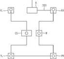
도 2에 도시된 바와 같이 실내에 멀티채널 스피커 시스템을 구현하기 위해서는 일반적으로 중앙부에 설치되는 오디오 본체(A)로부터 나오는 6개의 채널별 오디오 출력단자와 각각의 스피커인, 센터스피커(CS), 우퍼(W), 프론트라이트스피커(FR), 프론트레프트스피커(FL), 리어라이트스피커(RR), 및 리어레프트스피커(RL)를 연결하여 결선할 6조의 배선이 필요하게 된다.As shown in FIG. 2, in order to implement a multi-channel speaker system indoors, six channel-specific audio output terminals coming from an audio main body A installed in the center and each speaker, the center speaker CS and the woofer, respectively (W), six sets of wires to be connected by connecting the front light speaker FR, the front left speaker FL, the rear light speaker RR, and the rear left speaker RL are required.
따라서 이러한 배선을 사용하여 결선을 사용자가 행하는 것은 대단히 힘이 들어 설치비용이 소요되고, 특히 결선을 위한 배선들이 노출됨으로서 실내미관을 저해하게 된다. 또한 결선 시에는 각각의 스피커와 오디오본체의 출력단자가 대응되어 설치되어야 하므로 결선의 혼선이 유발되며 일단 설치를 하고 나면 재설치 시에는 모든 배선을 새로이 결선하여야 하므로 재설치에 어려움이 존재하고 있다.Therefore, it is very difficult for the user to make the wiring using such wiring, and installation cost is very high. In particular, the wiring for the wiring is exposed, thereby hindering the interior aesthetics. In addition, when the output terminal of each speaker and audio main body should be installed in correspondence with wiring, confusion of the wiring is caused, and once it is installed, it is difficult to reinstall because all wiring must be newly connected.
이런 문제점을 극복하고자 도 3에 나타난 무선 음향 시스템이 구현되었다.To overcome this problem, the wireless acoustic system shown in FIG. 3 has been implemented.
상기 도 3에 도시된 무선 음향 시스템은 각종의 음원을 처리하여 무선으로 송신하는 앰프부(150)와 상기 앰프부로부터 송출된 음향신호를 수신하고 처리하여 음향으로 출력하는 스피커부(170a, 170b,…, 170n)로 구성되어 있다.The wireless acoustic system shown in FIG. 3 includes an
상기와 같은 무선 음향 시스템은 기존의 유선 음향 시스템에 있어서의 스피커 배선에 관한 문제점을 어느 정도 해결할 수 있다. 허나 상기 무선 음향 시스템의 경우에는 스피커부에 무선으로 음향신호를 수신하기 위한 무선수신 장치, 수신된 신호를 음향으로 변환하기 위한 장치 및 상기 장치들에 전원을 공급하기 위한 전원장치 등이 필요하게 되어 스피커부의 부피가 커지게 되고 또한 전원을 공급하기 위한 배선이 별도로 필요한 문제점이 있다. 또한 음향신호가 수신되는 지를 확 인하기 위하여 스피커는 항상 전원을 소모하면서 대기상태(stand-by)를 유지하여야하고 무선 신호를 송/수신하므로 인체에 유해한 전자파 문제가 발생한다.The wireless acoustic system as described above can solve the problems related to the speaker wiring in the existing wired acoustic system to some extent. However, in the case of the wireless acoustic system, a wireless receiving apparatus for receiving a sound signal wirelessly, a device for converting a received signal into sound, and a power supply for supplying power to the apparatus are required. There is a problem in that the volume of the speaker unit is increased and a separate wiring for supplying power is required. Also, in order to check whether an acoustic signal is received, the speaker must maintain standby state by consuming power at all times and transmit / receive wireless signal, thus causing harmful electromagnetic problem.
상기의 문제점을 해결하고자 본 발명은, 단일의 전송선로를 이용하여 전력과 음향신호를 전송하여 복수개의 스피커의 복잡한 배선을 단일의 배선으로 통합하고, 배선의 종류에 무관하게 깨끗한 음질을 전송할 수 있는 스피커 시스템을 제공하기 위한 것이다.In order to solve the above problems, the present invention transmits power and sound signals using a single transmission line to integrate complex wiring of a plurality of speakers into a single wiring, and to transmit clean sound quality regardless of the wiring type. To provide a speaker system.
또한 복수개의 스피커마다 각각의 분리된 신호를 수신할 수 있도록 하여 멀티채널을 구현하는 스피커 시스템을 제공하며, 직류 전력을 전송하는 전송선로를 이용하여 음향장치와 스피커에 별도의 교류를 직류로 변환시키기 위한 변환모듈을 제거하고, 원하는 음향신호를 제한 없이 전송할 수 있는 음향시스템을 제공하기 위한 것이다.In addition, to provide a speaker system to implement a multi-channel by receiving a separate signal for each of a plurality of speakers, and to convert a separate AC to a direct current to the sound device and the speaker by using a transmission line for transmitting DC power The present invention provides a sound system capable of removing a conversion module for transmitting a desired sound signal without restriction.
상기 목적을 달성하기 위하여 본 발명은, 전력신호와 통신신호를 동시에 전송하는 PLC 시스템에 있어서, 전송하고자하는 음원을 입력받아 음향신호로 변환하고, 상기 음향신호를 전력신호에 중첩시켜 출력하는 음향장치부; 상기 음향장치부로부터 전송되는 상기 음향신호가 중첩된 전력신호에서 상기 음향신호를 추출하여 음원으로 출력하는 스피커부; 및 상기 음향장치부로부터 출력되는 상기 음향신호가 중첩된 전력신호를 상기 스피커부로 전송하는 유선 전송선로부를 포함하는 것을 특징으로 하는 PLC 스피커 시스템이다.
바람직하게는 상기 음향장치부는, 상기 음향신호를 전력신호에 중첩시켜 유선 전송선로부로 전송하기 위한 송신 PLC 통신회로를 포함하고, 상기 스피커부는, 상기 유선 전송선로부로부터 전송되는 상기 음향 신호가 중첩된 전력신호에서 상기 음향 신호를 추출하기 위한 수신 PLC 통신회로를 포함한다.
여기서 상기 음향 장치부는, 상기 음원을 디지털 음향신호로 처리하기 위한 디지털 처리회로를 포함하며, 상기 스피커부는, 상기 디지털 처리된 음향신호를 아날로그 음향신호로 변환하기 위한 D/A 변환회로; 상기 변환된 아날로그 음향신호를 증폭시키기 위한 앰프회로; 및 상기 증폭된 아날로그 음향신호를 출력하기 위한 적어도 하나 이상의 스피커를 포함하며, 상기 음향 장치부가, 디지털 처리된 음향신호를 전력신호에 중첩시켜 상기 유선 전송선로부로 출력하고, 상기 스피커부가, 상기 유선 전송선로부로부터 전송되는 상기 디지털 처리된 음향신호가 중첩된 전력신호에서 상기 디지털 처리된 음향신호를 추출하고 상기 디지털 처리된 음향신호를 아날로그 음향신호로 변환하여 음원으로 출력할 수 있다.
또한 본 발명은, 전력신호와 통신신호를 동시에 전송하는 PLC 시스템에 있어서, 전송하고자하는 음원을 입력받아 음향신호로 변환하여 전력신호와 중첩시켜 출력하거나, 음향신호가 중첩된 전력신호에서 음향신호를 추출하여 음원으로 출력하는, 복수개의 스피커폰부 및 상기 복수개의 스피커폰부 중 어느 하나의 스피커폰부에서 출력되는 음향신호가 중첩된 전력신호를, 상기 복수개의 스피커폰부 중 상기 음향신호가 중첩된 전력신호를 출력하는 스피커폰부를 제외한 나머지 스피커폰부 중 적어도 하나 이상의 스피커폰부에 전송하는 유선 전송선로부를 포함하는 것을 특징으로 하는 PLC 스피커 시스템이다.
바람직하게는 상기 스피커폰부는, 음원을 입력받기 위한 마이크; 입력받은 음원을 디지털로 처리하기 위한 디지털 처리회로; 디지털 처리된 음향신호를 전력신호에 중첩시켜 전송하기 위한 송신 PLC 통신회로; 디지털 처리된 음향신호가 중첩된 전력신호에서 음향신호를 추출하기 위한 수신 PLC 통신회로; 디지털 음향신호를 아날로그 음향신호로 변환하기 위한 D/A 변환회로; 아날로그 음향신호를 증폭시키기 위한 앰프회로; 및 증폭된 아날로그 음향신호를 음향으로 출력하기 위한 스피커를 포함한다.
나아가서 상기 유선 전송선로부는, 상기 전력신호 및 상기 전력신호에 중첩된 음향신호를 출력하는 콘센트를 포함할 수 있다.
한걸음 더 나아가서, 상기 유선 전송선로부는, 각각의 분산된 위치에 설치되며, 상기 전력신호에 중첩된 음향신호를 입출력하기 위한 복수개의 통신포트를 포함할 수 있다.
바람직하게는 상기 유선 전송선로부는, 교류 전압을 입력받아 직류전원으로 변환하여 복수개의 기기에 직류전원을 공급하는 직류 급전 네트워크를 더 포함하고, 상기 직류 급전 네트워크를 통해 상기 음향신호가 중첩된 전력신호를 전송할 수 있다.
나아가서 상기 유선 전송선로부는, 적어도 하나 이상의 건물 내에 망으로 구성되고; 상기 음향장치부는, 상기 건물 내의 방송을 위한 방송 장치를 포함하고, 상기 방송 장치로부터 출력되는 방송신호를 전력신호에 중첩시켜 상기 유선 전송선로부로 출력하며; 상기 스피커부는 상기 건물 내에 분산된 위치에 복수개 설치되어 상기 유선 전송선로부를 통해 전송되는 상기 방송신호가 중첩된 전력신호에서 방송신호를 추출하여 출력할 수 있다.
또한 상기 스피커부가 복수개 형성되고, 상기 복수개의 스피커부는 각각의 고유의 ID가 부여되어 있으며, 상기 음향 장치부는 각각의 스피커부에 대응되는 고유 ID 신호를 상기 음향신호에 실어 전력신호와 중첩시켜 상기 유선 전송선로부로 송신하고, 상기 복수개의 스피커부 각각은 상기 유선 전송선로부를 통해 수신되는 상기 전력신호에 중첩된 음향신호에 실린 고유 ID 신호가 자신의 고유 ID와 일치하는 음향신호를 추출하여 음향으로 출력할 수도 있다.In order to achieve the above object, the present invention is a PLC system for transmitting a power signal and a communication signal at the same time, the sound device to receive the sound source to be transmitted to convert the sound signal, and to superimpose the sound signal and output the power signal part; A speaker unit for extracting the sound signal from the power signal superimposed with the sound signal transmitted from the sound device unit and outputting the sound signal to a sound source; And a wired transmission line unit which transmits a power signal superimposed with the sound signal output from the sound device unit to the speaker unit.
Preferably, the sound device unit includes a transmission PLC communication circuit for transmitting the sound signal to the wired transmission line unit by superimposing the power signal, and the speaker unit includes the sound signal transmitted from the wired transmission line unit. And a receiving PLC communication circuit for extracting the sound signal from the power signal.
The sound device may include a digital processing circuit for processing the sound source into a digital sound signal, and the speaker unit may include a D / A conversion circuit for converting the digitally processed sound signal into an analog sound signal; An amplifier circuit for amplifying the converted analog sound signal; And at least one speaker for outputting the amplified analog sound signal, wherein the sound device unit outputs the digitally processed sound signal to the wired transmission line unit by superimposing a power signal, and the speaker unit is configured to output the wired transmission line. The digitally processed sound signal may be extracted from a power signal superimposed with the digitally processed sound signal transmitted from the furnace unit, and the digitally processed sound signal may be converted into an analog sound signal and output as a sound source.
In addition, the present invention, in the PLC system for transmitting a power signal and a communication signal at the same time, the sound source to be transmitted is converted into an acoustic signal and output superimposed with the power signal, or the sound signal is superimposed on the power signal superimposed A power signal overlapped with a sound signal output from one of a plurality of speaker phone units and a plurality of speaker phone units to be extracted and output as a sound source, and a power signal of the plurality of speaker phone units PLC speaker system, characterized in that it comprises a wired transmission line for transmitting to at least one speakerphone unit of the remaining speakerphone unit except for the speakerphone unit to output.
Preferably, the speakerphone unit, a microphone for receiving a sound source; A digital processing circuit for digitally processing the input sound source; A transmission PLC communication circuit for superimposing and transmitting the digitally processed sound signal on the power signal; A receiving PLC communication circuit for extracting a sound signal from a power signal superimposed with a digitally processed sound signal; A D / A conversion circuit for converting a digital sound signal into an analog sound signal; An amplifier circuit for amplifying analog sound signals; And a speaker for outputting the amplified analog sound signal as sound.
Further, the wired transmission line unit may include an outlet for outputting the power signal and an acoustic signal superimposed on the power signal.
Further, the wired transmission line unit may be provided at each distributed position and include a plurality of communication ports for inputting and outputting an acoustic signal superimposed on the power signal.
Preferably, the wired transmission line unit further includes a DC power supply network that receives an AC voltage and converts the power into DC power to supply DC power to a plurality of devices, and the power signal in which the sound signal is superimposed through the DC power supply network. Can be transmitted.
Furthermore, the wired transmission line unit is composed of a network in at least one or more buildings; The sound apparatus unit includes a broadcast apparatus for broadcasting in the building, and outputs the broadcast signal output from the broadcast apparatus to the wired transmission line unit by superimposing a power signal on the power signal; The speaker unit may be installed in a plurality of locations distributed in the building to extract and output a broadcast signal from a power signal overlapping the broadcast signal transmitted through the wired transmission line unit.
In addition, a plurality of speaker units are formed, and the plurality of speaker units are provided with respective unique IDs, and the sound apparatus unit carries a unique ID signal corresponding to each speaker unit on the sound signal and overlaps the power signal to provide the wired signal. Transmits to a transmission line unit, and each of the plurality of speaker units extracts an audio signal in which a unique ID signal superimposed on the sound signal superimposed on the power signal received through the wired transmission line unit matches its own ID and outputs the sound. You may.
삭제delete
삭제delete
삭제delete
삭제delete
삭제delete
삭제delete
삭제delete
삭제delete
삭제delete
나아가서 상기 스피커부는 헤드폰을 포함할 수 있으며, 상기 헤드폰은, 상기 전송선로부로부터 수신되는 상기 음향신호를 수신하기 위한 PLC 통신회로; 상기 수신된 디지털 음향신호를 아날로그 음향신호로 변환하기 위한 D/A 변환회로; 상기 아날로그 음향신호를 증폭시키기 위한 앰프회로; 및 상기 증폭된 아날로그 음향신호를 출력하기 위한 스피커를 포함할 수 있다.In addition, the speaker unit may include a headphone, the headphone, PLC communication circuit for receiving the sound signal received from the transmission line; A D / A conversion circuit for converting the received digital sound signal into an analog sound signal; An amplifier circuit for amplifying the analog sound signal; And a speaker for outputting the amplified analog sound signal.
이하에서는 기술한 발명의 목적을 달성하기 위한 본 발명의 구성 및 그 작용에 대하여 첨부된 도면을 참조하여 보다 상세히 설명한다.Hereinafter, with reference to the accompanying drawings, the configuration and operation of the present invention for achieving the object of the invention described in more detail.
도 4 및 도 5는 본 발명에 따른 PLC 스피커 시스템의 실시예를 개략적으로 도시한다.4 and 5 schematically show an embodiment of a PLC speaker system according to the invention.
도 4의 본 발명에 따른 실시예는 음향장치부(300), 전송선로부(330) 및 스피커부(350)로 구성된다.The embodiment according to the present invention of FIG. 4 is composed of an
음향장치부(300)는 디지털 처리회로(302)와 송신 PLC 통신회로(303)로 구성되며, 앰프부(300)에서는 전송하고자하는 음원을 디지털 처리회로(302)를 통해 디지털 음향신호로 처리하고 송신 PLC 통신회로(303)를 통해 상기 디지털 음향신호를 전력 신호에 중첩시켜 전송선로부(330)로 출력한다.The
스피커부(350)는 수신 PLC 통신회로(351), 디지털 처리회로(352), D/A 변환 회로(353), 앰프(355) 및 스피커(357)로 구성된다. 스피커부(350)에서는 전송선로부(330)를 통해 입력된 신호를 처리하여 음향으로 출력하게 되는데, 그 과정을 살펴보면, 수신 PLC 통신회로(351)에서 상기 중첩된 신호를 수신하여 상기 음향신호를 추출하고, 디지털 처리회로(352)에서 상기 추출된 음향신호를 처리하게 되며, D/A 변환회로(353)에서 상기 디지털 음향신호를 아날로그 음향신호로 변환하고, 상기 아날로그 신호를 앰프(355)로 증폭한 후 스피커(357)를 통해 음향을 출력하게 된다.The
나아가서 도 5에 도시된 바와 같이 음향장치부(300)에서 출력된 신호를 단일의 전송선로부(330)를 통해 복수개의 스피커부(350a,350b,…,350n)로 전송할 수 있다. 또한 음향장치부(300) 및 복수개의 스피커부(350a,350b,…,350n)는 전송선로부(330)로부터 전력을 공급받는다.Furthermore, as shown in FIG. 5, the signal output from the
따라서 전력공급 및 음향신호를 전송하기 위하여 기존의 각각의 스피커마다 필요한 다수의 배선수를 단일의 전송선로로 통합하여 전력과 음향신호를 전송함으로서 전선수를 최소로 줄일 수 있으며, 또한 음향신호를 디지털 신호로 전송하므로 전송선로 선의 품질에 관계없이 깨끗한 음향을 출력할 수 있다.Therefore, the number of wires required for each speaker for the power supply and sound signal transmission are integrated into a single transmission line to transmit power and sound signals, and the number of wires can be reduced to a minimum. Signal transmission allows clear sound output regardless of the quality of the transmission line.
도 6a 및 도 6b는 본 발명에 따른 PLC 스피커 시스템에 있어서, 전력과 음향신호를 전송하는 개략적인 방법을 도시한다.6A and 6B show a schematic method of transmitting power and sound signals in a PLC speaker system according to the present invention.
도 6a는 송신 PLC 회로(210)에서 교류 전원(230)에 음향신호(240)를 중첩(250)시켜 전송하고, 수신 PLC 회로(220)에서 중첩된 신호(250)로부터 음향신호(240)를 추출하여 음향을 재건하는 방법을 도시하고, 도 6b는 송신 PLC 회 로(410)에서 직류 전원(430)에 음향신호(440)를 중첩(450)시켜 전송하고 수신 PLC 회로(420)에서 중첩된 신호(450)로부터 음향신호(440)를 추출하여 음향을 재건하는 방법을 도시한다.FIG. 6A illustrates that an
본 발명에서는 상기와 같이 교류 전력선을 사용하여 음향신호를 전송할 수도 있으나, 교류 전원의 정현파에 음향신호를 중첩시켜야 하므로 원하는 데이터를 전송하는데 제한이 생기게 되며 전자파의 문제가 발생하므로, 직류 전력선을 사용하여 음향신호를 전송하여 교류 전력선을 사용하는 경우보다 전자파를 감소시키고 원하는 데이터를 제한 없이 송수신 할 수 있도록 하여 통신 고속화를 실현한다.In the present invention, it is also possible to transmit an acoustic signal using the AC power line as described above, but since the acoustic signal must be superimposed on the sine wave of the AC power, there is a limitation in transmitting desired data and the problem of electromagnetic waves occurs. By transmitting sound signals, it reduces electromagnetic waves and transmits / receives desired data without restriction than when AC power lines are used.
도 7은 본 발명에 따른 PLC 스피커 시스템에 있어서, 직류전력을 제공하는 전송선로부를 이용하여 음향신호를 전달하는 실시예를 개략적으로 도시한다.FIG. 7 schematically illustrates an embodiment in which a sound signal is transmitted using a transmission line unit providing DC power in a PLC speaker system according to the present invention.
음향장치부(300)는, 음원을 입력받아 디지털 처리회로(302)에서 음향신호를 디지털 신호로 처리하고, 디지털 음향신호(440)와 직류 전원(430)을 송신 PLC 통신회로(303)에서 중첩하여 중첩된 신호(450)를 직류 전력선인 전송선로부(330)로 출력한다.The
스피커부(350)는, 직류 전력선인 전송선로부(330)를 통해 입력되는 중첩된 신호(450)를 수신 PLC 통신회로(351)에서 직류 전원(430)과 디지털 음향신호(440)로 분리하게 되며, 분리된 직류 전원(430)은 스피커부(350)의 회로 및 스피커의 구동 전력을 위해 사용되고, 분리된 디지털 음향신호(440)는 디지털 처리회로(352)에서 처리하여 D/A 변환회로(353)를 통해 아날로그 신호로 변환되게 된다. 상기 아날로그 신호는 앰프(355)에서 증폭되어 스피커(357)를 통해 음향으로 출력된다.The
도 8 및 도 9는 본 발명에 따른 멀티채널 스피커 시스템을 구현하는 실시예를 도시한다.8 and 9 illustrate an embodiment for implementing a multi-channel speaker system according to the present invention.
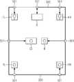
멀티채널 스피커 시스템으로 5.1 채널을 구현하는 경우, 프론트라이트 스피커(FR), 프론트레프트 스피커(FL), 센터 스피커(CS), 우퍼 스피커(W), 리어레프트 스피커(RL) 및 리어라이트 스피커(RR)의 6개 스피커를 구동하게 된다. 본 발명에서는 도 8에 도시된 바와 같이 이격된 위치에 설치된 각각의 스피커에 입력되는 음향신호를 단일의 전송선로(330)를 통하여 전송하게 된다.When implementing 5.1-channel with a multi-channel speaker system, the frontlight speaker (FR), front left speaker (FL), center speaker (CS), woofer speaker (W), rear left speaker (RL) and rear light speaker (RR Will drive 6 speakers). In the present invention, as shown in Figure 8 transmits the sound signal input to each speaker installed at a spaced position via a
앰프(A)는, 음원을 음향신호로 디지털 처리하고 송신 PLC 통신회로를 통해 직류전원과 상기 음향신호를 중첩하여 전송선로부(330)로 출력하는데, 여기서 앰프(A)는 상기 멀티채널을 구현하는 각각의 스피커에 고유의 ID를 부가하고 각각의 스피커에 해당하는 음향신호를 분리하여 전송선로부(330)로 전송하게 된다. 또한 상기 6개의 각각의 스피커(FL, FR, CS, W, PL, PR)는 자신의 고유 ID에 해당하는 신호를 수신하고, 수신 PLC 통신회로를 통해 수신된 신호에서 음향신호를 추출한다. 상기 추출된 디지털 음향신호를 아날로그 음향신호로 전환하여 앰프에서 증폭한 후 스피커를 통해 음향을 출력하게 된다.The amplifier A digitally processes a sound source into an acoustic signal and outputs the DC signal and the acoustic signal to the
나아가서 도 9에 도시된 바와 같이, 본 발명에서는 새로이 전송선로부를 설치할 필요 없이, 송배전 선로로부터 인입되는 교류 전압을 입력받아 직류전원으로 변환하여 복수개의 기기에 공급하는 직류 급전 네트워크가 설치된 경우, 이미 설치되어 있는 직류 급전 네트워크를 전송선로부로 이용하여 상기 직류 급전 네트워크를 통해 상기 음향신호를 전송할 수 있다. Furthermore, as shown in FIG. 9, in the present invention, the DC power supply network that receives the AC voltage input from the transmission and distribution line, converts the DC power into DC power, and supplies the plurality of devices is already installed. The sound signal may be transmitted through the DC power supply network by using the DC power supply network as a transmission line unit.
오디오 장치(A)는 가장 인접한 콘센트(501)에서 직류 전원을 공급받으면서 동시에 콘센트 또는 통신포트(501)로 음향신호를 출력한다. 이미 설치되어 있는 직류 전력선을 전송선로부(330)로 이용하여 상기 직류 전력선을 통해 전송되는 음향신호를 전송하고 상기 음향신호는 각각의 분산된 위치에 설치된 통신 포트(501)로 출력되게 된다. 각각의 스피커(FL, FR, CS, W, PL, PR)는 가장 인접한 위치에 설치된 통신포트(501)를 통해 자신의 고유의 ID에 해당하는 신호를 수신하여 음향신호를 처리 후 출력하게 된다. 이로 인해 다수의 스피커를 각각 이격된 위치에 간편히 설치할 수 있게 되어 배선의 복잡성을 해소할 수 있다.The audio device A outputs a sound signal to the outlet or the
도 10은 본 발명에 따른 학교나 아파트 등의 건물 내(600)에 있는 교실 또는 하나의 가정(610)에 방송을 하기 위한 방송 스피커 시스템을 구현한 실시예를 나타낸다.FIG. 10 illustrates an embodiment of implementing a broadcast speaker system for broadcasting in a classroom or a
도 10에 도시된 바와 같이, 학교나 아파트 등의 건물 내(600)의 모든 구역에 연결되는 전송선로부(330)를 형성하고, 방송 장치(620)와 각 구역(610)에 스피커(630)를 설치하여 방송시스템을 구축할 수 있다. 여기서 전송선로부(330)를 통해 전원과 방송신호가 전송되므로 상기 방송시스템의 각 구성요소인 방송 장치(620) 및 각각의 스피커(630)는 별도의 전원변환모듈을 가질 필요가 없으며 방송신호를 위한 별도의 배선도 필요가 없다. 또한 각 스피커마다 고유의 ID를 부과하고 방송 장치(620)에서 원하는 구역의 스피커의 고유 ID와 방송신호를 전송선로부(330)를 통해 전원과 중첩하여 전송하고, 해당 스피커는 자신의 고유 ID를 가진 신호에서 방송신호를 추출할 수 있는 제어회로를 포함하여, 해당 구역에만 방송이 전파될 수 있다.As shown in FIG. 10, a
또한 본 발명에 있어서, 상기 스피커부는 헤드폰을 포함할 수 있다.In addition, in the present invention, the speaker unit may include a headphone.
상기 헤드폰은, 전송선로부(330)로부터 수신되는 상기 음향신호를 수신하기 위한 PLC 통신회로; 상기 수신된 디지털 음향신호를 아날로그 음향신호로 변환하기 위한 D/A 변환회로; 상기 아날로그 음향신호를 증폭시키기 위한 앰프회로; 및 상기 증폭된 아날로그 음향신호를 출력하기 위한 스피커를 포함하고 있다.The headphone may include a PLC communication circuit for receiving the sound signal received from the
이와 같은 헤드폰을 인접한 위치에 설치된 통신포트(501)에 연결하여 출력되는 음향을 들을 수 있게 되는데, 상기의 본 발명에 따른 헤드폰 시스템은 정숙을 필요로 하는 교실이나 독서실 등의 장소에서 다수의 학생들에게 교육방송 등을 제공하는 경우에 있어서 그 효용이 높다.This headphone can be connected to the
나아가서 도 11은 본 발명에 따른 PLC 스피커 시스템에 있어서, 스피커폰에 대한 실시예를 개략적으로 도시한다.Furthermore, Fig. 11 schematically shows an embodiment of the speakerphone in the PLC speaker system according to the present invention.
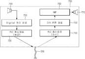
본 발명에 따른 스피커폰부(700)는, 마이크 등의 입력장치(710)를 통해 음원을 입력받고 상기 입력받은 음원을 디지털 처리회로(720)를 통해 디지털 음향신호로 처리하여 송신 PLC 통신회로(730)에서 전원과 상기 디지털 음향신호를 중첩하여 전송선로부(330)를 통해 출력하게 된다.The
또한 스피커폰부(700)는, 전송선로부(330)를 통해 입력되는 중첩된 신호를 수신 PLC 통신회로(740)에서 분리하여 음향신호와 전원을 추출하고, 상기 추출된 디지털 음향신호를 아날로그 신호로 D/A 변환회로(750)에서 변환하고 앰프(760)에서 증폭하여 스피커(770)를 통해 음향으로 출력하게 된다. 상기 추출된 전원은 스피커폰부(700)의 회로 등을 구동하기 위하여 사용된다.In addition, the
나아가서 도 12와 같이 상기 스피커폰부(700a, 700b, 700c, …, 700n)가 복수개 설치된 경우에, 각각의 스피커폰부는 자신의 고유의 ID를 가지고 있으며, 음향신호를 전송하고자 하는 스피커폰의 고유의 ID와 음향신호를 전원에 중첩시켜 전송하게 되면, 각각의 스피커폰은 자신의 고유의 ID를 가진 신호만을 수신하여 음향신호를 추출할 수 있게 된다. 이로써 전송선로를 이용하여 양방향 통신이 가능하게 된다.Furthermore, when a plurality of the
원하는 복수개의 스피커폰부에 음향신호를 전송하고자 하는 경우, 복수개 스피커폰부의 각각의 ID와 음향신호를 전원에 중첩시켜 전송하여 원하는 복수의 상대방과 통신이 가능하게 되므로 이를 통해 다자간 통신을 할 수도 있게 된다.When the sound signal is to be transmitted to the desired plurality of speakerphone units, the ID and sound signals of the plurality of speakerphone units may be superimposed on the power source to communicate with a plurality of desired counterparts, thereby enabling multilateral communication.
또한 위에서 상술한 본 발명은, 음향신호와 전원이 중첩된 신호를 전송선로를 통해 전송하였으나, 나아가서 본 발명은 중첩된 신호가 아닌 전송선로부 자체가 음향신호를 전송하기 위한 선과 전력을 전송하기 위한 선을 각각 별개로 포함하여, 상기 전송선로부를 통해 음향신호와 전력을 별개로 전송하는 PLC 스피커 시스템이 될 수 있다.In addition, the present invention described above, the sound signal and the power is superimposed to transmit the signal through the transmission line, but the present invention is not the overlapping signal, but the transmission line unit itself for transmitting the line and power for transmitting the sound signal It may be a PLC speaker system that includes a separate line, and transmits the sound signal and power separately through the transmission line unit.
본 발명에 의한, PLC 스피커 시스템은 본 발명의 기술적 사상의 범위 내에서 다양한 형태로 변형, 응용 가능하며 상기 실시예에 한정되지 않는다. 또한, 상기 실시예와 도면은 발명의 내용을 상세히 설명하기 위한 목적일 뿐, 발명의 기술적 사상의 범위를 한정하고자 하는 목적은 아니며, 이상에서 설명한 본 발명은 본 발명이 속하는 기술분야에서 통상의 지식을 가진 자에 있어 본 발명의 기술적 사상을 벗어나지 않는 범위 내에서 여러 가지 치환, 변형, 및 변경이 가능하므로 상기 실시예 및 첨부된 도면에 한정되는 것은 아님은 물론이며, 후술하는 청구범위뿐만이 아니라 청구범위와 균등 범위를 포함하여 판단되어야 한다.The PLC speaker system according to the present invention can be modified and applied in various forms within the scope of the technical idea of the present invention and is not limited to the above embodiments. In addition, the embodiments and drawings are merely for the purpose of describing the contents of the invention in detail, and are not intended to limit the scope of the technical idea of the invention, the present invention described above is common knowledge in the technical field to which the present invention belongs As those skilled in the art can have various substitutions, modifications, and changes without departing from the spirit and scope of the present invention, it is not limited to the embodiments and the accompanying drawings. Judgment should be made including scope and equivalence.
이상과 같은 본 발명에 의하면, 단일의 전송선로를 이용하여 스피커에 전력과 음향신호를 전송하고, 단일의 배선만으로 복수개의 스피커를 결선 할 수 있게 되므로 스피커 시스템 구축에 있어서 배선수를 최소로 하고 설비의 복잡성을 해소할 수 있다.According to the present invention as described above, power and sound signals can be transmitted to the speaker by using a single transmission line, and a plurality of speakers can be connected by only a single wiring, so the number of wiring is minimized in the speaker system construction. The complexity of the can be eliminated.
그리고 무선 통신의 경우와 같이 음향신호가 수신되는 지를 확인하기 위하여 스피커가 항상 전원을 소모하면서 대기상태(stand-by)를 유지할 필요가 없고, 전자파가 발생하지 않는다.In addition, as in the case of wireless communication, the speaker does not always need to maintain a stand-by while consuming power to check whether an acoustic signal is received, and no electromagnetic waves are generated.
또한 직류 전력선을 이용하므로 교류 전력선을 이용하는 경우보다 전자파가 감소하고 원하는 데이터를 제한 없이 송수신 할 수 있어 통신의 고속화를 실현할 수 있다.In addition, since a DC power line is used, electromagnetic waves are reduced and desired data can be transmitted and received without restriction compared to an AC power line, thereby achieving high speed communication.
나아가서 복수개의 스피커에 각각의 고유 ID를 부과하고 해당 ID에만 음향신호를 전송할 수 있으므로 멀티채널 스피커 시스템 및 건물 또는 아파트 등의 방송시스템에 적용할 수 있으며, 또한 스피커폰이나 인터폰 등에도 적용할 수 있다.Furthermore, since a unique ID is assigned to a plurality of speakers and an acoustic signal can be transmitted only to the corresponding ID, the speaker can be applied to a multi-channel speaker system and a broadcasting system such as a building or an apartment, and can also be applied to a speakerphone or an interphone.
그리고 아날로그 신호를 디지털 신호로 변환하여 전송하므로 전송매체인 전선의 품질에 관계없이 양질의 음향을 전달할 수 있다.And by converting analog signal to digital signal and transmitting, it is possible to deliver high quality sound regardless of the quality of wire which is transmission medium.
Claims (16)
Translated fromKoreanPriority Applications (1)
| Application Number | Priority Date | Filing Date | Title |
|---|---|---|---|
| KR1020060073631AKR100817789B1 (en) | 2006-08-04 | 2006-08-04 | PLC speaker system |
Applications Claiming Priority (1)
| Application Number | Priority Date | Filing Date | Title |
|---|---|---|---|
| KR1020060073631AKR100817789B1 (en) | 2006-08-04 | 2006-08-04 | PLC speaker system |
Publications (2)
| Publication Number | Publication Date |
|---|---|
| KR20080025769A KR20080025769A (en) | 2008-03-24 |
| KR100817789B1true KR100817789B1 (en) | 2008-03-31 |
Family
ID=39413430
Family Applications (1)
| Application Number | Title | Priority Date | Filing Date |
|---|---|---|---|
| KR1020060073631AActiveKR100817789B1 (en) | 2006-08-04 | 2006-08-04 | PLC speaker system |
Country Status (1)
| Country | Link |
|---|---|
| KR (1) | KR100817789B1 (en) |
Cited By (1)
| Publication number | Priority date | Publication date | Assignee | Title |
|---|---|---|---|---|
| KR20230073899A (en)* | 2021-11-19 | 2023-05-26 | (주) 일진앤드 | Daisy chain type speaker output system for ships using power line communication |
Families Citing this family (1)
| Publication number | Priority date | Publication date | Assignee | Title |
|---|---|---|---|---|
| KR200452270Y1 (en)* | 2009-03-03 | 2011-02-15 | 세계전자 주식회사 | Audio communication device using power line |
Citations (4)
| Publication number | Priority date | Publication date | Assignee | Title |
|---|---|---|---|---|
| KR200302580Y1 (en) | 2002-10-04 | 2003-01-30 | 마이크로닉 시스템주식회사 | A control system for plural audio signal and speaker group |
| KR20030011128A (en)* | 2003-01-08 | 2003-02-06 | 조갑훈 | Device for controlling the output of speakers |
| KR20050017806A (en)* | 2003-08-09 | 2005-02-23 | 한국스프라이트 주식회사 | Total control network speaker system |
| KR100514601B1 (en) | 2003-03-18 | 2005-09-13 | 한국스프라이트 주식회사 | Wiring method and apparatus for the multi-channel speakers system |
- 2006
- 2006-08-04KRKR1020060073631Apatent/KR100817789B1/enactiveActive
Patent Citations (4)
| Publication number | Priority date | Publication date | Assignee | Title |
|---|---|---|---|---|
| KR200302580Y1 (en) | 2002-10-04 | 2003-01-30 | 마이크로닉 시스템주식회사 | A control system for plural audio signal and speaker group |
| KR20030011128A (en)* | 2003-01-08 | 2003-02-06 | 조갑훈 | Device for controlling the output of speakers |
| KR100514601B1 (en) | 2003-03-18 | 2005-09-13 | 한국스프라이트 주식회사 | Wiring method and apparatus for the multi-channel speakers system |
| KR20050017806A (en)* | 2003-08-09 | 2005-02-23 | 한국스프라이트 주식회사 | Total control network speaker system |
Cited By (2)
| Publication number | Priority date | Publication date | Assignee | Title |
|---|---|---|---|---|
| KR20230073899A (en)* | 2021-11-19 | 2023-05-26 | (주) 일진앤드 | Daisy chain type speaker output system for ships using power line communication |
| KR102556630B1 (en)* | 2021-11-19 | 2023-07-19 | (주) 일진앤드 | Daisy chain type speaker output system for ships using power line communication |
Also Published As
| Publication number | Publication date |
|---|---|
| KR20080025769A (en) | 2008-03-24 |
Similar Documents
| Publication | Publication Date | Title |
|---|---|---|
| EP2286577B1 (en) | Method and apparatus for simplified interconnection and control of audio components of an home automation system | |
| DE69836084D1 (en) | A DISTRIBUTED STEREO SYSTEM | |
| US20100226100A1 (en) | Modular multimedia management and distribution system | |
| US9661429B2 (en) | System and method for modular on-demand audio processing, amplification and distribution | |
| CA3062773A1 (en) | Self-powered loudspeaker for sound masking | |
| KR100817789B1 (en) | PLC speaker system | |
| US9524294B2 (en) | Circuitry for a commentator and/or simultaneous translator system, operating unit and commentator and/or simultaneous translator system | |
| KR101106681B1 (en) | Two-way digital conversion audio transmission system | |
| KR20140130087A (en) | Public address system using power line communication | |
| KR101471484B1 (en) | Disital analog power amp applied sound network transfer system and operating method thereof | |
| CN101764654A (en) | Constant-pressure broadcast system by using a plurality of wireless forwarders for realizing addressable broadcasting | |
| CN101803183A (en) | Local broadcasting system | |
| CN104869518A (en) | Wall-mounted loud-speaking talkback terminal and loud-speaking talkback system | |
| KR20150041828A (en) | Power Line Communication Speaker System | |
| CN214205546U (en) | Sound amplification system based on POE power supply and DANTE | |
| EP2928205B1 (en) | Digital speaker system and electrical connection method for digital speaker system | |
| US8000479B2 (en) | Wireless speaker adapter | |
| CN207638854U (en) | A infrared ray passive loudspeaker box for extra-large area classroom | |
| US20080002843A1 (en) | Ripple digital amplifier system | |
| CN104104804B (en) | Mining intrinsic safety type voice system and voice device thereof | |
| KR100502657B1 (en) | Conference system embedded audio power amplifier | |
| US20100079205A1 (en) | Multi-Channel Amplifier | |
| JP3957353B2 (en) | Signal transmission equipment | |
| JP2013046262A (en) | Communication device, communication method, communication program and communication system | |
| KR100911462B1 (en) | Amplifier device and audio output device and audio signal output system thereby |
Legal Events
| Date | Code | Title | Description |
|---|---|---|---|
| A201 | Request for examination | ||
| PA0109 | Patent application | Patent event code:PA01091R01D Comment text:Patent Application Patent event date:20060804 | |
| PA0201 | Request for examination | ||
| E902 | Notification of reason for refusal | ||
| PE0902 | Notice of grounds for rejection | Comment text:Notification of reason for refusal Patent event date:20070829 Patent event code:PE09021S01D | |
| E701 | Decision to grant or registration of patent right | ||
| PE0701 | Decision of registration | Patent event code:PE07011S01D Comment text:Decision to Grant Registration Patent event date:20080318 | |
| GRNT | Written decision to grant | ||
| PG1501 | Laying open of application | ||
| PR0701 | Registration of establishment | Comment text:Registration of Establishment Patent event date:20080324 Patent event code:PR07011E01D | |
| PR1002 | Payment of registration fee | Payment date:20080325 End annual number:3 Start annual number:1 | |
| PG1601 | Publication of registration | ||
| PR1001 | Payment of annual fee | Payment date:20110221 Start annual number:4 End annual number:4 | |
| PR1001 | Payment of annual fee | Payment date:20120327 Start annual number:5 End annual number:5 | |
| FPAY | Annual fee payment | Payment date:20130326 Year of fee payment:6 | |
| PR1001 | Payment of annual fee | Payment date:20130326 Start annual number:6 End annual number:6 | |
| FPAY | Annual fee payment | Payment date:20140325 Year of fee payment:7 | |
| PR1001 | Payment of annual fee | Payment date:20140325 Start annual number:7 End annual number:7 | |
| FPAY | Annual fee payment | Payment date:20160308 Year of fee payment:9 | |
| PR1001 | Payment of annual fee | Payment date:20160308 Start annual number:9 End annual number:9 | |
| FPAY | Annual fee payment | Payment date:20170321 Year of fee payment:10 | |
| PR1001 | Payment of annual fee | Payment date:20170321 Start annual number:10 End annual number:10 | |
| FPAY | Annual fee payment | Payment date:20180321 Year of fee payment:11 | |
| PR1001 | Payment of annual fee | Payment date:20180321 Start annual number:11 End annual number:11 | |
| FPAY | Annual fee payment | Payment date:20190320 Year of fee payment:12 | |
| PR1001 | Payment of annual fee | Payment date:20190320 Start annual number:12 End annual number:12 | |
| PR1001 | Payment of annual fee | Payment date:20200325 Start annual number:13 End annual number:13 | |
| PR1001 | Payment of annual fee | Payment date:20220321 Start annual number:15 End annual number:15 | |
| PR1001 | Payment of annual fee | Payment date:20240325 Start annual number:17 End annual number:17 | |
| PR1001 | Payment of annual fee | Payment date:20250310 Start annual number:18 End annual number:18 |