KR100814685B1 - Vibrating mouse drive - Google Patents
Vibrating mouse driveDownload PDFInfo
- Publication number
- KR100814685B1 KR100814685B1KR1020070102856AKR20070102856AKR100814685B1KR 100814685 B1KR100814685 B1KR 100814685B1KR 1020070102856 AKR1020070102856 AKR 1020070102856AKR 20070102856 AKR20070102856 AKR 20070102856AKR 100814685 B1KR100814685 B1KR 100814685B1
- Authority
- KR
- South Korea
- Prior art keywords
- vibration
- mouse
- output
- voltage source
- cpu
- Prior art date
- Legal status (The legal status is an assumption and is not a legal conclusion. Google has not performed a legal analysis and makes no representation as to the accuracy of the status listed.)
- Expired - Fee Related
Links
Images


Classifications
- G—PHYSICS
- G06—COMPUTING OR CALCULATING; COUNTING
- G06F—ELECTRIC DIGITAL DATA PROCESSING
- G06F3/00—Input arrangements for transferring data to be processed into a form capable of being handled by the computer; Output arrangements for transferring data from processing unit to output unit, e.g. interface arrangements
- G06F3/01—Input arrangements or combined input and output arrangements for interaction between user and computer
- G06F3/03—Arrangements for converting the position or the displacement of a member into a coded form
- G06F3/033—Pointing devices displaced or positioned by the user, e.g. mice, trackballs, pens or joysticks; Accessories therefor
- G06F3/0354—Pointing devices displaced or positioned by the user, e.g. mice, trackballs, pens or joysticks; Accessories therefor with detection of 2D relative movements between the device, or an operating part thereof, and a plane or surface, e.g. 2D mice, trackballs, pens or pucks
- G06F3/03543—Mice or pucks
- G—PHYSICS
- G06—COMPUTING OR CALCULATING; COUNTING
- G06F—ELECTRIC DIGITAL DATA PROCESSING
- G06F3/00—Input arrangements for transferring data to be processed into a form capable of being handled by the computer; Output arrangements for transferring data from processing unit to output unit, e.g. interface arrangements
- G06F3/01—Input arrangements or combined input and output arrangements for interaction between user and computer
- G06F3/016—Input arrangements with force or tactile feedback as computer generated output to the user
- G—PHYSICS
- G06—COMPUTING OR CALCULATING; COUNTING
- G06F—ELECTRIC DIGITAL DATA PROCESSING
- G06F3/00—Input arrangements for transferring data to be processed into a form capable of being handled by the computer; Output arrangements for transferring data from processing unit to output unit, e.g. interface arrangements
- G06F3/01—Input arrangements or combined input and output arrangements for interaction between user and computer
- G06F3/03—Arrangements for converting the position or the displacement of a member into a coded form
- G06F3/033—Pointing devices displaced or positioned by the user, e.g. mice, trackballs, pens or joysticks; Accessories therefor
- G06F3/038—Control and interface arrangements therefor, e.g. drivers or device-embedded control circuitry
Landscapes
- Engineering & Computer Science (AREA)
- General Engineering & Computer Science (AREA)
- Theoretical Computer Science (AREA)
- Human Computer Interaction (AREA)
- Physics & Mathematics (AREA)
- General Physics & Mathematics (AREA)
- User Interface Of Digital Computer (AREA)
- Position Input By Displaying (AREA)
Abstract
Translated fromKoreanDescription
Translated fromKorean본 발명은 진동 마우스 구동 장치에 관한 것으로, 보다 상세하게는 진동 마우스를 구동함에 있어서, 진동의 크기 및 시간 등을 음향효과와 일치하도록 정밀하게 조정하면서 배선이 간단하도록 한 진동 마우스 구동 장치에 관한 것이다.The present invention relates to a vibrating mouse driving device, and more particularly, to a vibrating mouse driving device in which the wiring is simplified while precisely adjusting the magnitude and time of the vibration to match the sound effect in driving the vibrating mouse. .
정보 처리 기술의 발전에 따라, 게임기나 각종 휴대용 장치를 사용하는 사용자들은 이들 장치가 보다 현실감 있는 상호작용(interaction)을 제공할 것을 요구하고 있다. 이에 따라, 기존의 시각 및 청각 정보의 전달에 더하여 촉각 정보를 보다 현실감 있게 전달할 수 있는 하드웨어 환경을 제공하기 위한 방법에 대한 관심이 증가하고 있다.With the development of information processing technology, users of game machines or various portable devices are demanding that these devices provide more realistic interactions. Accordingly, there is an increasing interest in a method for providing a hardware environment that can deliver tactile information more realistically in addition to the transmission of conventional visual and auditory information.
이러한 요구에 따라 최근에는 각종 게임기나 컴퓨터 장치에 사용되는 마우스에 진동모터를 설치하여, 프로그램의 사용중 프로그램의 내용에 따라 마우스가 진동하도록 하는 진동 마우스가 제안되어 사용되고 있다.In response to these demands, recently, a vibrating mouse has been proposed and used in which a vibrating motor is installed in a mouse used in various game machines and computer devices, and the mouse vibrates according to the contents of the program while the program is in use.
이러한 종래의 진동 마우스는 통상 스피커 출력 신호를 받아서 진동 모터를 구동하는 방식으로 그 예로서는 대한민국 실용신안등록 제 319960호에 마우스 기능과 스피커 기능을 동시에 수행하도록 고안된 음향출력 수단을 가진 마우스 장치가 제안되어 있으며, 상기한 마우스 신호 케이블인 USB 케이블에 컴퓨터의 사운드 카드 출력단자에 연결되어 오디오신호를 전달받기 위한 오디오 신호 케이블이 더 연결되어 있어, 마우스 장치의 배선이 복잡해지는 문제가 있었다.Such a conventional vibration mouse is a method of driving a vibration motor by receiving a speaker output signal, for example, a mouse device having a sound output means designed to simultaneously perform the mouse function and speaker function in the Republic of Korea Utility Model Registration No. 319960 has been proposed In addition, since the audio signal cable for receiving the audio signal is further connected to the sound card output terminal of the computer to the USB cable which is the mouse signal cable, there is a problem in that the wiring of the mouse device is complicated.
그리고 이와 같은 스피커 신호를 이용한 마우스는 컴퓨터에서 발생하는 모든 음원에 대해서 진동 모터가 구동하기 때문에 진동의 효과음 외에 잡음이나 기타 불필요한 음원에도 진동 모터가 구동하기 때문에 실제 게임이나 어플리케이션의 음향 효과에 따른 진동 느낌이 미약하고 전혀 다른 느낌을 전하는 문제점이 있었다.In addition, the mouse using the speaker signal drives the vibration motor for all sound sources generated from the computer, so the vibration motor is driven not only by the sound effect of the vibration but also by noise or other unnecessary sound sources. There was an issue that conveyed this feeble and totally different feeling.
한편, 전기 및 전자 제어시스템에서 전원전압은 필수적이다. 이는 전원전압이 해당 전기나 전자제품의 각 부품들이나 회로소자들의 작동을 위한 동작전압원이 되기 때문이다. 전기 및 전자제품의 동작전압은 1.4V, 1.8V, 3.3V,10V, 24V 등등으로 다양하며 또한 각자의 동작전압 범위를 가지고 있다. 통상적으로 동작전압은 미리 설정된 동작전압 범위 내에서 인가되어야만 각 부하 즉 회로 및 부품소자가 안정하게 작동된다.On the other hand, power supply voltage is essential in electric and electronic control systems. This is because the power supply voltage becomes an operating voltage source for the operation of each component or circuit element of the electric or electronic product. The operating voltages of electrical and electronic products vary from 1.4V, 1.8V, 3.3V, 10V, 24V, etc., and have their own operating voltage range. In general, the operating voltage must be applied within a predetermined operating voltage range to ensure stable operation of each load, that is, the circuit and the component elements.
한편, 전기나 전자 제품의 부하에는 동작전압을 선택적으로 공급해야할 필요성이 있고, 동작전압을 승압 또는 강하시켜 공급해주어야 할 필요성이 있다. 어떤 부하에서는 구동전압을 시간적으로 가변되도록 공급해 주어야할 필요성도 있다.On the other hand, there is a need to selectively supply the operating voltage to the load of the electrical or electronic products, there is a need to supply by boosting or lowering the operating voltage. In some loads, it is necessary to supply the driving voltage to be variable in time.
따라서 전기, 전자 및 제어 시스템에 정전압원이 포함된 가변전압원을 제공할 수 있으면 전기, 전자 제어 시스템에 많이 활용 및 응용될 수 있으므로, 조정가능한 전압원을 공급할 수 있는 장치 및 그를 적용한 응용장치가 요망되며, 이러한 요망에 의하여 본 출원인은 대한민국 등록특허 10-0757242호에 가변전압원을 제공 하는 기술을 제안한 바 있으며, 본원발명은 상기한 본 출원인의 선등록 건에서 제안한 가변전압원을 이용하여 사실감 있는 촉감을 느낄 수 있도록 하는 진동마우스의 개발 요구에 의하여 발명하게 되었다.Therefore, if a variable voltage source including a constant voltage source can be provided to the electric, electronic and control system, it can be widely utilized and applied to the electric and electronic control system. Therefore, a device capable of supplying an adjustable voltage source and an application device using the same are desired. , The applicant has proposed a technology for providing a variable voltage source in the Republic of Korea Patent No. 10-0757242, the present invention, using the variable voltage source proposed in the above-mentioned pre-registration of the present applicant feel a realistic touch The invention has been invented by the demand for the development of a vibrating mouse.
본 발명은 상기한 바와 같은 요구에 의하여 진동 마우스에 가변전압원을 구비하여, 사실감 있는 촉감 전달이 가능하도록 함과 아울러, 사용 중 프로그램의 내용에 맞도록 조도가 조절되도록 하는 진동 마우스 구동 장치를 제공하는 데 발명의 목적이 있다.The present invention is to provide a vibrating mouse drive device that is provided with a variable voltage source in the vibrating mouse in accordance with the above-described requirements, to enable a realistic tactile transmission and to adjust the illuminance to match the contents of the program during use. There is an object of the invention.
상기한 목적을 달성하기 위한 본 발명에 따른 진동 마우스 구동 장치는 각종 동작명령을 입력하는 키보드, 마우스 등의 입력수단과, 컴퓨터의 각종 동작을 제어하는 CPU, 각종 데이터가 기록되는 메모리, 상기한 CPU의 제어명령에 따라 오디오 신호를 이용하여 진동 패턴 윈도우 파일을 작성하여 메모리에 저장하는 패턴 작성용 프로그램 모듈, 상기한 입력수단을 통해서 게임이나 각종 어플리케이션 실행 명령이 입력되면 CPU에 의하여 실행되며 진동 패턴 파일을 음향 효과와 동일한 시점에서 메모리로부터 함수로 호출하는 게임 또는 각종 어플리케이션 실행 모듈, 상기한 게임 또는 각종 어플리케이션 실행 모듈로부터 출력되는 진동 패턴 파일을 포함한 파일이 전송되는 DLL모듈, 상기한 DLL 모듈로부터 진동 마우스 제어신호를 전달받아 출력하는 윈도우의 휴먼 인터페이스 드라이브 모듈로 구성되는 컴퓨터; 상기한 컴퓨터로부터 출력되는 신호를 전달받아 진동 패턴 내용(진동의 세기, 진동시간)을 받고 분석하여 그에 해당하는 PWM 신호를 만들어 내는 CPU, 상기한 CPU로부터 출력되는 제어신호에 따라 진동 모터(M)를 구동하는 가변 전압원 회로로 구성되 는 진동 마우스;로 구성된다.Vibrating mouse driving apparatus according to the present invention for achieving the above object is a keyboard, a mouse and the like input means for inputting various operation commands, a CPU for controlling various operations of the computer, a memory for recording various data, the CPU A pattern generation program module for creating a vibration pattern window file using an audio signal and storing the result in a memory according to a control command of the program. When a game or various application execution commands are input through the above input means, the vibration pattern file is executed. A DLL module to which a file including a vibration pattern file output from a game or various application execution modules, the game or various application execution modules is called from the memory at the same time as the sound effect, and the vibration mouse from the DLL module. Window to receive control signal and output A computer configured with a human interface drive module; CPU that receives the signal output from the computer and receives the vibration pattern contents (vibration intensity, vibration time) and generates a corresponding PWM signal, the vibration motor (M) according to the control signal output from the CPU It consists of; a vibration mouse consisting of a variable voltage source circuit for driving the.
한편, 상기한 진동 마우스에는 발광다이오드가 더 구비되고, 상기한 가변 전압원 회로는 진동마우스의 CPU로부터 출력되는 제어신호에 따라 진동 모터(M)와 함께 발광다이오드를 구동한다.The vibration mouse further includes a light emitting diode, and the variable voltage source circuit drives the light emitting diode together with the vibration motor M according to a control signal output from the CPU of the vibration mouse.
그리고 상기한 가변 전압원 회로는 입력단에 입력전압이 연결되고 출력단으로 출력전압이 출력되는 트랜지스터와, 두 입력신호 전압레벨을 비교하여 상기 트랜지스터를 제어하는 연산증폭기를 포함하여 구성하되, 상기 출력단으로부터 궤환되어 상기 연산증폭기의 일입력단으로 인가되는 전압의 궤환율을 선택적으로 가변시키는 궤환회로와, 상기 연산증폭기의 타입력단으로 시간적으로 가변가능한 제어신호에 대응된 제어입력전압이 인가되게 구성된다.The variable voltage source circuit includes a transistor having an input voltage connected to an input terminal and outputting an output voltage to an output terminal, and an operational amplifier comparing the two input signal voltage levels to control the transistor, and being fed back from the output terminal. And a feedback circuit for selectively varying the feedback rate of the voltage applied to one input terminal of the operational amplifier, and a control input voltage corresponding to a control signal that is variable in time to the type force terminal of the operational amplifier.
본 발명에 의하면 오디오 신호를 이용하여 진동 패턴 윈도우 파일로 만들어 주는 프로그램을 사용하여 게임이나 어플리케이션의 실제 음향 효과에 가장 알맞은 진동 패턴을 만들어내고 그 진동 패턴 파일을 게임이나 어플리케이션 소스에서 음향 효과와 함께 출력함으로써 진정한 음향효과에 일치하는 진동 패턴으로 진동 모터를 제어할 수 있게 되는 것이다.According to the present invention, a vibration pattern window file is generated using an audio signal to generate a vibration pattern most suitable for a real sound effect of a game or application, and the vibration pattern file is output together with a sound effect from a game or application source. This allows the vibration motor to be controlled with vibration patterns that match the true acoustics.
또한, 상기한 진동패턴은 가변전압원에 의하여 강도제어가 가능하고, 역방향진동 등의 촉감도 느낄 수 있게 되므로 실제와 유사나 촉감을 체험할 수 있게 되는 것이다.In addition, the vibration pattern can control the intensity by the variable voltage source, and can also feel the touch such as reverse vibration, so that the user can experience the similarity or tactile feeling.
아울러, 컴퓨터와 진동 마우스는 하나의 케이블로만 연결되어 있으며 마우스 의 기본 동작을 전혀 방해하지 않고 윈도우의 HID를 통해서 마우스와 진동 모터의 제어 신호를 같이 처리하므로, 사용상의 만족도가 향상되는 효과가 있다.In addition, the computer and the vibrating mouse are connected with only one cable, and the control signals of the mouse and the vibrating motor are processed together through the HID of the window without interfering with the basic operation of the mouse.
이하 본 발명의 실시예를 하기에서 첨부된 도면을 참조하여 보다 상세하게 살펴본다.Hereinafter, an embodiment of the present invention will be described in more detail with reference to the accompanying drawings.
도 1은 본 발명에 따른 진동 마우스의 구성을 나타내는 블록도이다.1 is a block diagram showing the configuration of a vibration mouse according to the present invention.
본 발명에 따른 진동 마우스 구동 장치는 진동마우스를 구동하기 위한 제어신호를 출력하는 컴퓨터(200)와 상기한 컴퓨터(200)의 제어신호에 따라 구동이 제어되는 진동 마우스(300)로 구성된다.Vibrating mouse driving apparatus according to the present invention is composed of a
상기한 구성에서 컴퓨터(200)는 각종 동작명령을 입력하는 키보드, 마우스 등의 입력수단(210)과, 컴퓨터의 각종 동작을 제어하는 CPU(220), 각종 데이터가 기록되는 메모리(230), 상기한 CPU(220)의 제어명령에 따라 오디오 신호를 이용하여 진동 패턴 윈도우 파일을 작성하여 메모리(230)에 저장하는 패턴 작성용 프로그램 모듈(240), 상기한 입력수단(210)을 통해서 게임이나 각종 어플리케이션 실행 명령이 입력되면 CPU(220)에 의하여 실행되며 진동 패턴 파일을 음향 효과와 동일한 시점에서 메모리로부터 함수로 호출하는 게임 또는 각종 어플리케이션 실행 모듈(250), 상기한 게임 또는 각종 어플리케이션 실행 모듈(250)로부터 출력되는 진동 패턴 파일을 포함한 파일이 전송되는 DLL모듈(260), 상기한 DLL 모듈(260)로부터 진동 마우스 제어신호를 전달받아 출력하는 윈도우의 휴먼 인터페이스 드라이브(Human Interface Driver) 모듈(270)로 구성된다.In the above configuration, the
그리고, 상기한 진동 마우스(300)는 컴퓨터(200)로부터 출력되는 신호를 전달받아 진동 패턴 내용(진동의 세기, 진동시간)을 받고 분석하여 그에 해당하는 PWM 신호를 만들어 내는 CPU(310), 상기한 CPU(310)로부터 출력되는 제어신호에 따라 진동 모터(M)와 발광다이오드(LED1, LED2, LED3)를 구동하는 가변 전압원 회로(320)로 구성된다.In addition, the
상기한 바와 같은 구성을 갖는 진동 마우스 구동 장치는 아래와 같이 구동된다.The vibrating mouse drive device having the configuration as described above is driven as follows.
1) 우선, 마우스를 구성하는 진동 모터에 전송할 패턴을 만든다.1) First, create a pattern to transmit to the vibration motor constituting the mouse.
작업자는 컴퓨터에 구비된 키보드, 마우스 등의 입력수단을 이용하여 컴퓨터의 CPU에서 오디오 신호를 이용하여 진동 패턴 윈도우 파일을 작성하는 패턴 작성용 프로그램 모듈을 구동시켜 실행하고자 하는 게임이나 어플리케이션에서 발생하는 음향 효과를 분석해서 일차 진동 패턴을 만들고 다시 다양한 형태의 진동 패턴을 일차 진동 패턴에 추가 변경 또는 삭제하여 2차 진동 패턴 또는 그 이상의 매우 다양한 형태의 진동 패턴을 생성하여 현재 발생하는 음향 효과에 가장 최적화된 진동 패턴 파일을 만들어 컴퓨터의 메모리에 기록하며, 이와 같이 제작된 패턴은 윈도우 고유의 패턴 파일 구조인 DLL파일 구조를 가지고 있다.The operator generates a sound generated by a game or application to be executed by driving a pattern creation program module for creating a vibration pattern window file using an audio signal from a CPU of a computer using input means such as a keyboard and a mouse provided in the computer. Analyze the effect to create a primary vibration pattern, and then change or delete various types of vibration patterns to the primary vibration pattern to generate a wide variety of vibration patterns of the secondary vibration pattern or more, which is most optimized for the current sound effects. The vibration pattern file is created and recorded in the memory of the computer. The pattern thus produced has a DLL file structure, which is a Windows-specific pattern file structure.
2) 게임 또는 어플리케이션 실행 모듈에서 진동 패턴 파일을 호출한다.2) Call the vibration pattern file in the game or application execution module.
입력수단을 통해서 게임이나 각종 어플리케이션 실행 명령이 입력되면 컴퓨터의 CPU는 게임 또는 각종 어플리케이션 실행 모듈을 통해서 음향 효과에 의해 만들어진 진동 패턴 파일을 음향 효과와 동일한 시점에서 메모리로부터 함수로 호출 하여 DLL모듈로 전송하는데, 이 과정에서 본 발명에 의하면 단지 하나의 함수만 호출해주면 된다.When a game or various application execution command is input through the input means, the CPU of the computer calls the vibration pattern file created by the sound effect through the game or various application execution module to the DLL module by calling the function from the memory to the function at the same time as the sound effect. In this process, according to the present invention, only one function needs to be called.
그 예로서, HID_Write(Volume, Time1, Time2)가 있으며, 상기한 구성에서 Volume은 진동모터의 세기를 조절하고 0에서 255까지 지정할 수 있으며, Time1은 정방향 진동 시간으로 단위는 msec이고 0-255까지 지정할 수 있다. 또한 Time2는 역방향 진동시간을 나타내고 단위는 msec이며 0-255까지 지정할 수 있다.For example, HID_Write (Volume, Time1, Time2). In the above configuration, Volume adjusts the strength of the vibration motor and can be specified from 0 to 255, and Time1 is the forward vibration time in msec and 0-255. Can be specified. Time2 also represents the reverse oscillation time. The unit is msec and can be set from 0-255.
3)HID 모듈에서 진동 마우스의 CPU로 진동 패턴을 전달한다.3) Transmit vibration pattern from HID module to CPU of vibration mouse.
진동패턴의 내용을 전달받은 DLL 모듈은 윈도우의 휴먼 인터페이스 드라이브(Human Interface Driver) 모듈(이하 HID 모듈이라 함)에 진동 패턴 신호를 전달하면 상기한 HID 모듈은 그 신호를 진동 마우스에 장착되어 있는 CPU에 전달한다.The DLL module receiving the vibration pattern transmits a vibration pattern signal to the Windows Human Interface Driver module (hereinafter referred to as the HID module). The HID module transmits the signal to the vibration mouse. To pass on.
상기한 구성에서 HID란 일반적으로 컴퓨터에 새로운 장치를 부착할 때 필요한 드라이버를 자동으로 인식하여 설치하는 것을 말하며, 드라이버란 컴퓨터에 새로운 장치 및 기기를 연결하게 되면 컴퓨터는 그 장치가 무엇인지 인식을 하지 못하게 되므로, 제품을 만든 회사에서는 그 기기를 인식할 수 있는 표준 규약을 만들어 컴퓨터에 설치하여 그 기기를 인식하게 하는 것을 말하며, 진동 마우스도 이러한 규약을 따르고 있어 진동 마우스를 컴퓨터에 장착할 때 자동으로 장치 드라이브를 인식하도록 되어 있다.In the above configuration, the HID generally means to automatically recognize and install a driver required for attaching a new device to the computer. The driver means that when a new device and device are connected to the computer, the computer does not recognize what the device is. This means that the company that made the product creates a standard protocol for recognizing the device and installs it on a computer to recognize the device. The vibrating mouse also follows these rules. It is designed to recognize the device drive.
4) 진동 마우스의 CPU에서 가변 전압원 회로에 PWM신호를 출력한다.4) The vibration mouse outputs a PWM signal to the variable voltage source circuit.
진동 마우스의 CPU는 진동 패턴 내용(진동의 세기, 진동시간)을 받고 분석하여 그에 해당하는 PWM 신호를 만들어 내고 진동 모터 구동 드라이브인 가변 전압원 회로에 PWM신호를 발생시킨다. 그리고 3개의 LED의 밝기를 상기한 진동패턴에 맞도록 조절하기 위한 PWM 신호도 함께 발생시킨다.The CPU of the vibration mouse receives and analyzes the vibration pattern contents (vibration intensity and vibration time), generates a corresponding PWM signal, and generates a PWM signal in a variable voltage source circuit which is a vibration motor driving drive. A PWM signal is also generated to adjust the brightness of the three LEDs to match the vibration pattern.
5) 가변 전압원 회로에서 진동 모터와 LED를 구동한다.5) Drive the vibration motor and LED in the variable voltage source circuit.
진동 모터 구동 드라이브와 LED 구동 드라이브는 PWM신호를 받아서 전압 레벨로 신호를 바꾸어서 진동 모터를 구동하고, LED의 조도를 조절한다.The vibration motor drive drive and the LED drive drive receive the PWM signal and change the signal to the voltage level to drive the vibration motor and adjust the illuminance of the LED.
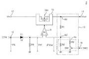
상기한 구성에서 가변 전압원 회로는 종래 기술에서 설명한 바와 같이 대한민국 등록특허 10-0757242호에 제시된 회로를 사용하며, 그 대표적인 구성은 도 2에 나타내는 바와 같다.In the above configuration, the variable voltage source circuit uses the circuit shown in Korean Patent No. 10-0757242 as described in the prior art, and the representative configuration thereof is as shown in FIG. 2.
가변전압원 회로부(2)는, N채널 모오스 전계효과트랜지스터(이하 "트랜지스터"라 칭함) TR1, 다이오드 D1, 저항 R4, 연산증폭기(4), 궤환회로(10), N채널 트랜지스터 TR1의 과전류 및 과열 차단을 위한 과전류 및 과열 차단회로(6)로 구성된다.The variable voltage
상기에서 트랜지스터 TR1은, 그 드레인단에 입력단(12)을 통해서 입력전압 Vin이 인가되고, 소오스단에는 출력단(14)이 연결되는 바, 그 출력단(14)으로는 출력전압 Vout가 출력되며, 그 게이트단으로는 두 입력신호를 비교 증폭하는 연산증폭기(4)로부터 출력된 게이트 제어신호가 인가되게 구성한다.In the transistor TR1, an input voltage Vin is applied to the drain terminal thereof through the
상기한 도 2에서 Vref는 연산증폭기(4)의 비반전입력단(+)에 인가되는 전압이고, Av는 연산증폭기(4)의 전압이득이며, β는 궤환률로서, 가변전압원 회로부(2)의 출력전압 Vout는 하기 수학식 1로부터 구할 수 있다.In FIG. 2, Vref is a voltage applied to the non-inverting input terminal (+) of the

상기한 수학식 1에서, 궤환률 β와 연산증폭기(4)의 전압이득 Av의 곱 즉, β* Av의 값이 식의 분모에 위치한 "1"을 무시할 수 있을 만큼 충분히 크게하면, 가변전압원 회로부(2)의 출력전압 Vout는 Vout=Vref/β로 표현할 수 있게 되므로, 출력전압 Vout를 하기와 같은 방법으로 하여 정전압원으로 형성할 수 있다.In the above Equation 1, if the product of the feedback factor β and the voltage gain Av of the
즉, 연산증폭기(4)의 비반전입력단(+)에 인가되는 제어입력전압 Vref와 연산증폭기(4)의 반전입력단(-)으로 궤환되는 출력전압 Vout의 궤환률 β를 모두 상수(constant)화하면 된다.That is, both the control input voltage Vref applied to the non-inverting input terminal (+) of the
그 반대로 출력전압 Vout를 가변전압원으로 나타나도록 하기 위해 하기와 같은 방법으로 하면된다. 즉, 제어입력전압 Vref 및/또는 궤환률 β중 적어도 하나를 변수화하면 된다. 다시 설명하면, 제어입력전압 Vref 및/또는 궤환률 β를 시간에 따라 연속적 혹은 급진적으로 바뀌는 변수로 구성하게되면 출력전압 Vout는 가변전압원이 되는 것이다.On the contrary, in order to make the output voltage Vout appear as a variable voltage source, the following method may be used. That is, at least one of the control input voltage Vref and / or the feedback rate β may be variable. In other words, if the control input voltage Vref and / or feedback rate β are configured as variables that change continuously or radically with time, the output voltage Vout becomes a variable voltage source.
제어입력전압 Vref와 궤환률 β를 변수로 구성하는 것에 대해서 구체적으로 설명하면 하기와 같다.The configuration of the control input voltage Vref and the feedback rate β as variables will now be described in detail.
먼저, 연산증폭기(4)의 비반전입력단(+)에 인가되는 제어입력전압 Vref를 변수로 구성하기 위해, 제어신호입력단(16)에 인가되는 제어신호 CTRL를 시간적으로 변화하도록 구현하며, 상기한 CTRL의 소스(source) 종류로 본원발명에서는 PWM(Pulse Width Modulation)신호를 사용한다.First, in order to configure the control input voltage Vref applied to the non-inverting input terminal (+) of the
다음으로, 궤환률 β를 변수로 구성하기 위해서 도 2에 도시된 바와 같은 궤환회로(10)를 구성한다. 궤환률 β는 회로특성상 연속적으로 변화하도록 구현하지는 못한다.Next, the
궤환회로(10)에서 N채널 트랜지스터 TR1의 소오스단과 출력단(14) 사이의 노드 N1에 저항 R1의 일단을 연결하고 그 저항 R1의 타단을 노드 N2를 통해서 연산증폭기(4)의 반전입력단(-)에 연결한다. 노드 N2에는 일단이 접지된 저항 R2를 연결하고, 저항 R2에 병렬연결된 저항 R3의 일단을 연결하되, 저항 R3의 타단에는 일단이 접지된 스위치 SW1이 연결된다. 스위치 SW1에는 스위치제어신호 SWC가 인가되고, 스위치 SW1의 온(on) 또는 오프(off)에 따라 궤환율 β가 두 가지 상태를 갖도록 한다.In the
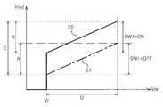
따라서 궤환률 β는 두 가지 값(제1,제2 궤환율)을 가지게 되며, 도 3에 도시된 바와 같이 가변전압원 회로부(2)에 스위치 SW1이 오프되었을 경우 동작특성곡선 E1을, 스위치 SW1이 온되었을 경우 동작특성곡선 E2를 나타낸다.Therefore, the feedback rate β has two values (first and second feedback rates). When the switch SW1 is turned off in the variable voltage
도 3에서 D는 제어입력전압 Vref의 가변전압 입력신호영역이다. Vt는 다이오드 D1의 턴온전압으로서, 가변전압원 회로부(2)를 동작 또는 비동작되게하는 기준전압이다. 아울러 다이오드 D1의 턴온전압 Vt는 제어단(16)으로 인가되는 잡음이나 미약한 전원에 의해 가변전압원 회로부(2)가 오작동되는 것을 방지하는 역할도 한다. 그러므로 가변전압원 회로부(2)의 출력전압 Vout는 다이오드 D1에 인가되는 제어신호 CTRL의 전압레벨 VRL이 다이오드 턴온전압 Vt이상이 되는 경우에만 출력된 다.In FIG. 3, D is a variable voltage input signal region of the control input voltage Vref. Vt is a turn-on voltage of the diode D1, which is a reference voltage for operating or deactivating the variable voltage
출력 다이나믹레인지(dynamic range) C는 동작특성곡선 E1에 의한 출력 다이나믹레인지(dynamic rage) A와 동작특성곡선 E2에 의한 출력 다이나믹레인지 B에 의해서 정해지고, 출력 다이나믹레인지 A와 B는 중간부분에서 서로 중첩되어진다. 동작특성곡선 E1에 의한 출력 다이나믹레인지(dynamic rage) A와 동작특성곡선 E2에 의한 출력 다이나믹레인지 B가 서로 중첩되게 하는 것은 궤환회로(10)의 스위치 SW1에 직렬 연결된 저항 R3의 저항값을 조정함으로써 달성되어진다.The output dynamic range C is determined by the output dynamic range A by the operating characteristic curve E1 and the output dynamic range B by the operating characteristic curve E2. Overlap. The overlap of the output dynamic range A by the operating characteristic curve E1 and the output dynamic range B by the operating characteristic curve E2 is adjusted by adjusting the resistance value of the resistor R3 connected in series with the switch SW1 of the
그러므로 출력전압 Vout의 출력 다이나믹레인지 C는 거의 다이나믹 레인지 'A+B' 정도까지 확장되어진다.Therefore, the output dynamic range C of the output voltage Vout is almost extended to the dynamic range 'A + B'.
한편, 가변전압원 회로부(2)의 제어신호입력단(16)의 전단에는 인가되는 제어신호 CTRL의 특성에 따라 필터나 바이어스회로부와 같은 신호처리부가 선택적으로 구비되어지는데, 본 발명과 같이 CTRL의 소스가 PWM신호일 경우에는 제어신호 입력단(16)의 전단에는 적분 및 고주파 성분 제거를 위한 LPF(Low Pass Filter)가 신호처리부로서 구비된다.On the other hand, in the front end of the control
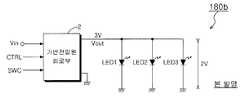
그리고, 상기한 바와 같이 구성된 가변전압원 회로가 LED구동회로(180b)를 구동하는 것을 도 4를 참조하여 살펴보면, 가변전압원 회로부(2)에는 입력전원 Vin과 제어신호 CTRL(필수)과 스위치제어신호 SWC(선택)가 입력되고, 제어신호 CTRL이 PWM신호이므로, 사용자의 정의에 따라 출력전압 Vout이 가변출력된다. 그러므로 예컨대, 스위치제어신호 SWC의 제어 하의 LED의 출력동작범위가 1.8 ∼ 2.3V 이면 가변전압원 회로부(2)의 출력전압 Vout는 1.8 ∼ 2.3V 전압범위 내에서 가변출력되고 그에 따른 LED의 밝기도 가변되어진다.In addition, referring to FIG. 4, the variable voltage source circuit configured as described above drives the
도 5a 및 도 5b는 본 발명의 실시 예에 따른 가변전압원을 이용한 모터 구동 장치(184b,184c)의 실시예를 나타내는 도면이다.5A and 5B are diagrams illustrating embodiments of the
도 5a에서 본 발명의 가변전압원 응용 진동모터장치(184b)의 가변전압원 회로부(2)는 제어신호 CTRL이 PWM신호이므로, 출력전압 Vout이 가변출력된다. 그러므로 예컨대, 진동모터(186)의 동작범위가 2 ∼ 3.2V 이면 가변전압원 회로부(2)의 출력전압 Vout는 2 ∼ 3.2V 전압범위 내에서 가변출력되고 그에 따른 진동모터(186)의 회전속도도 가변되어진다.In the variable voltage
그리고 도 5b의 가변전압원 응용 진동모터장치(184c)는 도 5a의 가변전압원 회로부(2)의 후단에 스위칭부(20)를 이용한 풀브릿지회로부를 더 구비함으로써 선택신호 SEL의 논리상태에 따라 진동모터(186)에 인가되는 전류의 방향을 바꾸어줌으로써 진동모터(86)의 회전 방향을 바꿀 수 있다. 예컨대, 선택신호 SEL이 논리 '하이'상태이면 진동모터(86)는 시계 방향으로 회전하고, 선택신호 SEL이 논리 '로우'상태이면 진동모터(86)는 반시계방향으로 회전된다.In addition, the variable voltage source application
이 경우 풀브릿지 회로의 일입력단은 가변전압원 회로부(2)로부터의 가변 출력전압 Vout에 연결되고 타입력단은 접지에 연결된다.In this case, one input terminal of the full bridge circuit is connected to the variable output voltage Vout from the variable voltage
도 1은 본 발명에 따른 진동 마우스의 구성을 나타내는 블록도1 is a block diagram showing the configuration of a vibration mouse according to the present invention
도 2는 본 발명에 따른 가변 전압원 회로의 구성을 나타내는 블록도2 is a block diagram showing a configuration of a variable voltage source circuit according to the present invention.
도 3은 도 2의 가변전압원 회로부 특성곡선도3 is a characteristic curve diagram of a variable voltage source circuit of FIG. 2;
도 4는 가변전압원 회로부의 LED 구동예를 나타내는 블록도4 is a block diagram showing an LED driving example of a variable voltage source circuit portion;
도 5a 및 도 5b는 가변전압원 회로부의 모터 구동예를 나타내는 블록도5A and 5B are block diagrams showing motor driving examples of the variable voltage source circuit portion.
Claims (3)
Translated fromKoreanPriority Applications (3)
| Application Number | Priority Date | Filing Date | Title |
|---|---|---|---|
| KR1020070102856AKR100814685B1 (en) | 2007-10-12 | 2007-10-12 | Vibrating mouse drive |
| PCT/KR2007/005785WO2009048194A1 (en) | 2007-10-12 | 2007-11-16 | Drive system of vibration mouse |
| US12/679,898US20100207746A1 (en) | 2007-10-12 | 2007-11-16 | Drive system of vibration mouse |
Applications Claiming Priority (1)
| Application Number | Priority Date | Filing Date | Title |
|---|---|---|---|
| KR1020070102856AKR100814685B1 (en) | 2007-10-12 | 2007-10-12 | Vibrating mouse drive |
Publications (1)
| Publication Number | Publication Date |
|---|---|
| KR100814685B1true KR100814685B1 (en) | 2008-03-18 |
Family
ID=39410910
Family Applications (1)
| Application Number | Title | Priority Date | Filing Date |
|---|---|---|---|
| KR1020070102856AExpired - Fee RelatedKR100814685B1 (en) | 2007-10-12 | 2007-10-12 | Vibrating mouse drive |
Country Status (3)
| Country | Link |
|---|---|
| US (1) | US20100207746A1 (en) |
| KR (1) | KR100814685B1 (en) |
| WO (1) | WO2009048194A1 (en) |
Cited By (1)
| Publication number | Priority date | Publication date | Assignee | Title |
|---|---|---|---|---|
| KR101606791B1 (en) | 2015-09-08 | 2016-03-28 | 박재성 | System providing Real Time Vibration according to Frequency variation and Method providing the vibration |
Families Citing this family (7)
| Publication number | Priority date | Publication date | Assignee | Title |
|---|---|---|---|---|
| US9639187B2 (en)* | 2008-09-22 | 2017-05-02 | Apple Inc. | Using vibration to determine the motion of an input device |
| CN102289307B (en)* | 2011-09-02 | 2013-08-07 | 北京希格玛和芯微电子技术有限公司 | Mouse button identification circuit, device and mouse |
| KR101181505B1 (en)* | 2012-02-28 | 2012-09-10 | 한국과학기술원 | Haptic interface having asymmetric reflecting points |
| KR102091077B1 (en)* | 2012-12-14 | 2020-04-14 | 삼성전자주식회사 | Mobile terminal and method for controlling feedback of an input unit, and the input unit and method therefor |
| US20150241970A1 (en)* | 2014-02-27 | 2015-08-27 | Samsung Electronics Co., Ltd. | Method and apparatus for providing haptic effect |
| CN111261185A (en)* | 2020-01-10 | 2020-06-09 | 腾讯音乐娱乐科技(深圳)有限公司 | Method, device, system, equipment and storage medium for playing audio |
| TWI785865B (en)* | 2021-10-28 | 2022-12-01 | 華碩電腦股份有限公司 | Electronic device with vibration function and vibration driving method |
Citations (3)
| Publication number | Priority date | Publication date | Assignee | Title |
|---|---|---|---|---|
| JP2008005001A (en)* | 2006-06-20 | 2008-01-10 | Sanyo Electric Co Ltd | Chopper comparator and successive comparison a/d converter employing the same |
| JP2008000005A (en)* | 2006-06-20 | 2008-01-10 | Shizuoka Prefecture | Agent for ameliorating dysphagia and food for ameliorating dysphagia |
| JP2008002001A (en)* | 2006-06-21 | 2008-01-10 | Hideo Sumino | Helmet |
Family Cites Families (13)
| Publication number | Priority date | Publication date | Assignee | Title |
|---|---|---|---|---|
| US5889670A (en)* | 1991-10-24 | 1999-03-30 | Immersion Corporation | Method and apparatus for tactilely responsive user interface |
| US5825308A (en)* | 1996-11-26 | 1998-10-20 | Immersion Human Interface Corporation | Force feedback interface having isotonic and isometric functionality |
| US6449400B1 (en)* | 1996-06-21 | 2002-09-10 | Kabushiki Gaisha Inter Action | Sensing optical fiber and sensor system |
| US7561142B2 (en)* | 1999-07-01 | 2009-07-14 | Immersion Corporation | Vibrotactile haptic feedback devices |
| KR20000058537A (en)* | 2000-06-12 | 2000-10-05 | 안재현 | A mouse type input device which generates vibration in order to realize computer game and a computer system for driving it |
| US6703550B2 (en)* | 2001-10-10 | 2004-03-09 | Immersion Corporation | Sound data output and manipulation using haptic feedback |
| US20060017691A1 (en)* | 2004-07-23 | 2006-01-26 | Juan Manuel Cruz-Hernandez | System and method for controlling audio output associated with haptic effects |
| US7268863B2 (en)* | 2004-08-06 | 2007-09-11 | The United States Of America As Represented By The Secretary Of The Navy | Natural fiber span reflectometer providing a spread spectrum virtual sensing array capability |
| US7768698B2 (en)* | 2004-08-30 | 2010-08-03 | Independent Administrative Institution, Japan Agency For Marine-Earth Science And Technology | Raman amplifier and optical communication system |
| US7702502B2 (en)* | 2005-02-23 | 2010-04-20 | Digital Intelligence, L.L.C. | Apparatus for signal decomposition, analysis and reconstruction |
| US8072595B1 (en)* | 2005-08-29 | 2011-12-06 | Optech Ventures, Llc | Time correlation system and method |
| FR2903541B1 (en)* | 2006-07-10 | 2009-11-20 | Institut Francais De Rech Pour Lexploitation De La Mer Ifremer | DEEP SUBMARINE NETWORK AND DEPLOYMENT DEVICE |
| US8121442B2 (en)* | 2008-12-24 | 2012-02-21 | At&T Intellectual Property I, L.P. | Optical fiber surveillance topology |
- 2007
- 2007-10-12KRKR1020070102856Apatent/KR100814685B1/ennot_activeExpired - Fee Related
- 2007-11-16USUS12/679,898patent/US20100207746A1/ennot_activeAbandoned
- 2007-11-16WOPCT/KR2007/005785patent/WO2009048194A1/enactiveApplication Filing
Patent Citations (3)
| Publication number | Priority date | Publication date | Assignee | Title |
|---|---|---|---|---|
| JP2008005001A (en)* | 2006-06-20 | 2008-01-10 | Sanyo Electric Co Ltd | Chopper comparator and successive comparison a/d converter employing the same |
| JP2008000005A (en)* | 2006-06-20 | 2008-01-10 | Shizuoka Prefecture | Agent for ameliorating dysphagia and food for ameliorating dysphagia |
| JP2008002001A (en)* | 2006-06-21 | 2008-01-10 | Hideo Sumino | Helmet |
Non-Patent Citations (3)
| Title |
|---|
| 공개특허 제2000-0058537호 |
| 공개특허 제2002-0018181호 |
| 공개특허 제2005-0015235호 |
Cited By (1)
| Publication number | Priority date | Publication date | Assignee | Title |
|---|---|---|---|---|
| KR101606791B1 (en) | 2015-09-08 | 2016-03-28 | 박재성 | System providing Real Time Vibration according to Frequency variation and Method providing the vibration |
Also Published As
| Publication number | Publication date |
|---|---|
| WO2009048194A1 (en) | 2009-04-16 |
| US20100207746A1 (en) | 2010-08-19 |
Similar Documents
| Publication | Publication Date | Title |
|---|---|---|
| KR100814685B1 (en) | Vibrating mouse drive | |
| KR100383769B1 (en) | Pumping voltage regulation circuit | |
| WO2006026169A3 (en) | Method and apparatus for customizing of a power supply based on load characteristic data | |
| KR100891120B1 (en) | Method of forming pattern file for sensor element driving and control of electric / electronic device and sensor element driving and control device of electric / electronic device using pattern file | |
| GB2591355A (en) | Audio circuitry | |
| WO2006059438A1 (en) | Voltage generating circuit, constant current circuit and light emitting diode driving circuit | |
| CN1134759C (en) | Buzzer driving circuit | |
| EP0667673B1 (en) | Constant-current circuit using field-effect transistor | |
| US20240329767A1 (en) | Drive Circuit, Tactile Sensation Generator, And Method For Controlling Drive Circuit | |
| JP4760054B2 (en) | Drive circuit and current control method | |
| EP1526638A3 (en) | Variable gain amplifier | |
| KR100757242B1 (en) | LED, motor, oscillator driving device, actuator device, power supply device, control device, control device of mobile communication terminal device using voltage source control device and variable voltage source | |
| US8847441B2 (en) | Device and method for generating a current pulse | |
| CN101938876B (en) | Led drive circuit | |
| KR100415610B1 (en) | Microphone input sensitivity automatic converter | |
| US7425848B2 (en) | Integrated driver circuit structure | |
| KR20030013858A (en) | Regulator system for controlling output voltage and control method thereof | |
| KR20000029074A (en) | Inverter circuit with duty cycle control | |
| US7424120B2 (en) | Method and apparatus for volume control | |
| KR100431629B1 (en) | reference voltage generating circuit of the high speed current switch | |
| KR20030092584A (en) | The Vpp-generating circuit and the Vpp-generating method in the semiconductor memory devices | |
| JP2908123B2 (en) | Semiconductor device | |
| KR960003445B1 (en) | Line regulation with source apparatus | |
| KR960001256Y1 (en) | Color Gain Automatic Control | |
| JP2005160212A (en) | FET drive device and method for generating FET drive voltage in FET drive device |
Legal Events
| Date | Code | Title | Description |
|---|---|---|---|
| A201 | Request for examination | ||
| PA0109 | Patent application | St.27 status event code:A-0-1-A10-A12-nap-PA0109 | |
| PA0201 | Request for examination | St.27 status event code:A-1-2-D10-D11-exm-PA0201 | |
| A302 | Request for accelerated examination | ||
| PA0302 | Request for accelerated examination | St.27 status event code:A-1-2-D10-D17-exm-PA0302 St.27 status event code:A-1-2-D10-D16-exm-PA0302 | |
| E701 | Decision to grant or registration of patent right | ||
| PE0701 | Decision of registration | St.27 status event code:A-1-2-D10-D22-exm-PE0701 | |
| GRNT | Written decision to grant | ||
| PR0701 | Registration of establishment | St.27 status event code:A-2-4-F10-F11-exm-PR0701 | |
| PR1002 | Payment of registration fee | St.27 status event code:A-2-2-U10-U11-oth-PR1002 Fee payment year number:1 | |
| PG1601 | Publication of registration | St.27 status event code:A-4-4-Q10-Q13-nap-PG1601 | |
| PN2301 | Change of applicant | St.27 status event code:A-5-5-R10-R13-asn-PN2301 St.27 status event code:A-5-5-R10-R11-asn-PN2301 | |
| PR1001 | Payment of annual fee | St.27 status event code:A-4-4-U10-U11-oth-PR1001 Fee payment year number:4 | |
| FPAY | Annual fee payment | Payment date:20120412 Year of fee payment:5 | |
| PR1001 | Payment of annual fee | St.27 status event code:A-4-4-U10-U11-oth-PR1001 Fee payment year number:5 | |
| P22-X000 | Classification modified | St.27 status event code:A-4-4-P10-P22-nap-X000 | |
| LAPS | Lapse due to unpaid annual fee | ||
| PC1903 | Unpaid annual fee | St.27 status event code:A-4-4-U10-U13-oth-PC1903 Not in force date:20130313 Payment event data comment text:Termination Category : DEFAULT_OF_REGISTRATION_FEE | |
| PC1903 | Unpaid annual fee | St.27 status event code:N-4-6-H10-H13-oth-PC1903 Ip right cessation event data comment text:Termination Category : DEFAULT_OF_REGISTRATION_FEE Not in force date:20130313 |