KR100814410B1 - Defect detection method of a substrate on which a semiconductor element is formed - Google Patents
Defect detection method of a substrate on which a semiconductor element is formedDownload PDFInfo
- Publication number
- KR100814410B1 KR100814410B1KR1020070004688AKR20070004688AKR100814410B1KR 100814410 B1KR100814410 B1KR 100814410B1KR 1020070004688 AKR1020070004688 AKR 1020070004688AKR 20070004688 AKR20070004688 AKR 20070004688AKR 100814410 B1KR100814410 B1KR 100814410B1
- Authority
- KR
- South Korea
- Prior art keywords
- inspection
- image
- substrate
- region
- defect
- Prior art date
- Legal status (The legal status is an assumption and is not a legal conclusion. Google has not performed a legal analysis and makes no representation as to the accuracy of the status listed.)
- Expired - Fee Related
Links
Images


Classifications
- H—ELECTRICITY
- H01—ELECTRIC ELEMENTS
- H01L—SEMICONDUCTOR DEVICES NOT COVERED BY CLASS H10
- H01L22/00—Testing or measuring during manufacture or treatment; Reliability measurements, i.e. testing of parts without further processing to modify the parts as such; Structural arrangements therefor
- G—PHYSICS
- G01—MEASURING; TESTING
- G01N—INVESTIGATING OR ANALYSING MATERIALS BY DETERMINING THEIR CHEMICAL OR PHYSICAL PROPERTIES
- G01N21/00—Investigating or analysing materials by the use of optical means, i.e. using sub-millimetre waves, infrared, visible or ultraviolet light
- G01N21/84—Systems specially adapted for particular applications
- G01N21/88—Investigating the presence of flaws or contamination
- G01N21/95—Investigating the presence of flaws or contamination characterised by the material or shape of the object to be examined
- G01N21/956—Inspecting patterns on the surface of objects
- G01N21/95607—Inspecting patterns on the surface of objects using a comparative method
- G—PHYSICS
- G01—MEASURING; TESTING
- G01N—INVESTIGATING OR ANALYSING MATERIALS BY DETERMINING THEIR CHEMICAL OR PHYSICAL PROPERTIES
- G01N21/00—Investigating or analysing materials by the use of optical means, i.e. using sub-millimetre waves, infrared, visible or ultraviolet light
- G01N21/84—Systems specially adapted for particular applications
- G01N21/88—Investigating the presence of flaws or contamination
- G01N21/95—Investigating the presence of flaws or contamination characterised by the material or shape of the object to be examined
- G01N21/9501—Semiconductor wafers
- G—PHYSICS
- G06—COMPUTING OR CALCULATING; COUNTING
- G06T—IMAGE DATA PROCESSING OR GENERATION, IN GENERAL
- G06T7/00—Image analysis
- G06T7/0002—Inspection of images, e.g. flaw detection
- G06T7/0004—Industrial image inspection
- G06T7/0006—Industrial image inspection using a design-rule based approach
- G—PHYSICS
- G06—COMPUTING OR CALCULATING; COUNTING
- G06T—IMAGE DATA PROCESSING OR GENERATION, IN GENERAL
- G06T2207/00—Indexing scheme for image analysis or image enhancement
- G06T2207/30—Subject of image; Context of image processing
- G06T2207/30108—Industrial image inspection
- G06T2207/30148—Semiconductor; IC; Wafer
Landscapes
- Engineering & Computer Science (AREA)
- Physics & Mathematics (AREA)
- General Physics & Mathematics (AREA)
- Biochemistry (AREA)
- Analytical Chemistry (AREA)
- Chemical & Material Sciences (AREA)
- General Health & Medical Sciences (AREA)
- Life Sciences & Earth Sciences (AREA)
- Immunology (AREA)
- Pathology (AREA)
- Health & Medical Sciences (AREA)
- Computer Vision & Pattern Recognition (AREA)
- Quality & Reliability (AREA)
- Theoretical Computer Science (AREA)
- Manufacturing & Machinery (AREA)
- Computer Hardware Design (AREA)
- Microelectronics & Electronic Packaging (AREA)
- Power Engineering (AREA)
- Investigating Materials By The Use Of Optical Means Adapted For Particular Applications (AREA)
- Testing Or Measuring Of Semiconductors Or The Like (AREA)
Abstract
Translated fromKoreanDescription
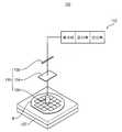
Translated fromKorean도 1은 본 발명의 기판 검사 방법을 수행하기에 적합한 결함 검사 장치를 나타내는 개략적인 도면이다.1 is a schematic diagram showing a defect inspection apparatus suitable for performing the substrate inspection method of the present invention.
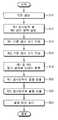
도 2는 본 발명의 일실시예에 따른 기판 검사 방법을 나타내는 공정 흐름도를 나타낸다.2 is a process flow diagram illustrating a substrate inspection method according to an embodiment of the present invention.
도 3은 디램 장치의 셀 영역의 일부를 나타내는 평면도이다.3 is a plan view showing a part of a cell region of a DRAM device.
도 4는 셀 영역의 가장자리 부위를 확대 도시한 평면도이다.4 is an enlarged plan view of an edge portion of a cell region.
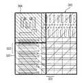
도 5는 본 실시예의 디램 장치에서 설정된 제1 및 제2 검사 영역을 나타낸다.5 shows the first and second inspection areas set in the DRAM device of this embodiment.
본 발명은 반도체 소자가 형성된 기판의 검사 방법에 관한 것이다. 보다 상세하게는, 반도체 소자가 형성된 기판을 간단한 공정을 통해 빠른 시간 내에 검사하는 방법에 관한 것이다.The present invention relates to a method for inspecting a substrate on which a semiconductor element is formed. More specifically, the present invention relates to a method of inspecting a substrate on which a semiconductor device is formed, in a short time through a simple process.
반도체 소자의 제조 공정에서 공정이 복잡해지고, 패턴의 선폭이 매우 미세 해짐에 따라, 패턴과 패턴 간의 브릿지, 패턴의 끊김, 패턴 내의 보이드 발생 등과 같은 결함이 매우 증가되고 있다.As the process becomes complicated in the manufacturing process of the semiconductor device and the line width of the pattern becomes very fine, defects such as bridging between the pattern and the pattern, breakage of the pattern, and generation of voids in the pattern are increasing.
이에 따라, 상기 반도체 소자를 제조하는 단위 공정들을 수행한 이 후에는 상기 공정을 수행하는 중에 발생된 결함을 검사하는 공정이 수행되어야 한다. 이 때, 상기 검사 공정이 정확하게 이루어져야만 결함이 존재하지 않는 상태에서 후속 공정이 진행될 수 있어 수율의 저하를 감소시킬 수 있다. 그러므로, 미세한 결함을 정확하게 검사할 수 있는 고성능을 갖는 기판 검사 장치가 요구되고 있다.Accordingly, after performing the unit processes of manufacturing the semiconductor device, a process of inspecting defects generated during the process should be performed. In this case, the inspection process may be performed correctly, and subsequent processes may be performed in the absence of defects, thereby reducing a decrease in yield. Therefore, there is a demand for a substrate inspection apparatus having a high performance capable of inspecting minute defects accurately.
일반적으로, 반도체 소자의 결함을 검사하기 위한 비교 알고리즘은 랜덤 모드(Random Mode)와 어레이 모드(Array Mode)로 분류된다.In general, a comparison algorithm for inspecting a defect of a semiconductor device is classified into a random mode and an array mode.
상기 랜덤 모드는 검사를 수행하기 위한 다이(Die)와 그와 인접한 다이를 서로 비교하는 다이 투 다이(Die to Die) 방식이다. 즉, 결함을 검사하기 위한 다이에 위치하는 제1 영역과, 그와 인접하는 다이에서 상기 제1 영역과 동일한 영역을 서로 비교하여, 서로 다른 픽셀을 찾아내고 이를 결함으로 분류하는 방식이다. 상기 랜덤 모드의 경우, 서로 인접하는 다이들에서 동일한 영역을 서로 비교하기 때문에 반도체 소자에서 반복적으로 패턴이 형성되어 있는 영역 뿐 아니라 반복되지 않고 비규칙적으로 패턴이 형성되어 있는 영역까지 결함을 검사할 수 있는 장점이 있다. 그러나, 상기 랜덤 모드로 결함을 검출하면, 다이와 다이들 간에 색깔의 차이(Color Variation)나 포커스(focus)의 차이에 의해 노이즈가 발생되기 쉽기 때문에 결함 검출력이 다소 떨어지는 문제가 있다.The random mode is a die to die method in which a die for performing an inspection and a die adjacent thereto are compared with each other. That is, the first region located on the die for inspecting the defect and the same region as the first region on the adjacent die are compared with each other to find different pixels and classify them as defects. In the random mode, since the same areas are compared with each other in the adjacent dies, defects can be inspected not only in the region where the pattern is formed repeatedly in the semiconductor device but also in the region where the pattern is formed irregularly and irregularly. There is an advantage. However, when the defect is detected in the random mode, noise is likely to be generated due to color variation or focus difference between the die and the die, so that the defect detection power may be somewhat reduced.
한편, 상기 어레이 모드는 동일한 다이 내에서 반복되는 패턴 부위를 일정 간격으로 이미지를 비교하여 다른 픽셀을 찾아내고 이를 결함으로 분류하는 방식이다. 상기 어레이 모드의 경우 동일한 다이 내에서 서로 인접하는 영역들 간을 비교하기 때문에 반도체 소자에서 반복적으로 패턴이 형성되어 있는 부위에만 검사가 가능하다. 그러나, 상기 어레이 모드는 동일 다이 내에서 서로 인접하는 영역들에 대해 비교가 이루어지기 때문에 색깔의 차이(Color Variation)나 포커스(focus)의 차이가 거의 나지 않아서 상기 랜덤 모드에 비해 더욱 정확하게 결함을 검출할 수 있다. 구체적으로, 상기 어레이 모드는 상기 랜덤 모드에 비해 신호(signal)와 노이즈 (noise)의 비율(SNR)이 약 1.5배 정도 높다. 이와 같이, 상기 어레이 모드로 검사하는 경우 신호와 노이즈의 비율이 커서 미세한 결함도 정확하게 검사할 수 있다. 상기와 같은 검출력의 차이가 있으므로, 고집적도를 갖는 반도체 소자가 형성되어 있는 기판은 상기 어레이 모드를 이용하여 주로 결함 검사가 이루어진다.On the other hand, the array mode is a method of finding a different pixel by comparing the image at a predetermined interval to repeat the pattern portion in the same die and classifies it as a defect. In the case of the array mode, since the regions are adjacent to each other in the same die, inspection may be performed only on a portion where the pattern is repeatedly formed in the semiconductor device. However, since the array mode compares adjacent areas within the same die, color variation or focus is hardly detected so that defects are detected more accurately than the random mode. can do. Specifically, the array mode has a signal ratio (SNR) of about 1.5 times higher than that of the random mode. As described above, in the case of the inspection in the array mode, the ratio of the signal and the noise is large, so that even minute defects can be accurately inspected. Since there is a difference in detection power as described above, a defect inspection is mainly performed on a substrate on which a semiconductor device having high integration is formed using the array mode.
그런데, 반도체 소자 내에는 X축 방향으로 반복되는 패턴들이 형성되어 있는 영역 및 Y축 방향으로 반복되는 패턴들이 형성되어 있는 영역이 각각 존재한다. 이와 같이, 반복되는 패턴의 방향이 서로 다른 영역들에 대해서 각각 검사가 이루어져야 한다.However, in the semiconductor device, there are regions where patterns that are repeated in the X-axis direction and regions where patterns that are repeated in the Y-axis direction are formed. As such, the inspections must be performed for regions having different directions of repeated patterns.
즉, 최초에 기판을 광학부에 대해 X축의 방향으로 스캔하면서 이미지를 수득하고, 상기 X축 방향으로 반복되는 패턴들이 형성되어 있는 영역에 대해서 반복되는 패턴 부위를 일정 간격으로 이미지를 비교함으로써 결함을 검출한다. 이 후에는, 상기 기판을 90도로 수평 회전시킨 후 광학부에 대해 X축의 방향으로 스캔하면서 이미지를 수득하고, 상기 Y축 방향으로 반복되는 패턴들이 형성되어 있는 영역 에 대해서 반복되는 패턴 부위를 일정 간격으로 이미지를 비교함으로써 결함을 검출한다. 이는, 기판의 스캔 방향으로만 이미지를 취득할 수 있도록 TDI(Time Delay Integration) 센서 칩의 배열이 고정되어 있기 때문에 스캔 방향으로 반복되는 패턴에 대해서만 어레이 검사가 가능하기 때문이다. 이와 같이, 동일한 기판에 대해 X축 방향 및 Y축 방향으로 각각 스캔하면서 검사가 이루어져야 하기 때문에 검사 시간이 매우 길어지는 문제가 있다.That is, the image is first obtained by scanning the substrate in the direction of the X axis with respect to the optical unit, and the defect is removed by comparing the images at a predetermined interval with respect to the region where the patterns are repeated in the X axis direction. Detect. After this, the substrate is horizontally rotated by 90 degrees, and then an image is obtained by scanning in the direction of the X axis with respect to the optical unit, and the pattern region which is repeated with respect to the region where the patterns are repeated in the Y axis direction is formed at a predetermined interval. Defects are detected by comparing images. This is because the array inspection is possible only for the pattern repeated in the scanning direction because the arrangement of the TDI (Time Delay Integration) sensor chip is fixed so that the image can be acquired only in the scanning direction of the substrate. As described above, the inspection time has to be very long because inspection must be performed while scanning the same substrate in the X-axis direction and the Y-axis direction, respectively.
또한, 상기 반복 패턴이 형성되어 있는 영역의 가장자리 부위는 이웃하는 영역과 다소 다른 형상을 갖기 때문에 스캔 방향으로 일정 크기만큼 비교하는 어레이 모드에 의해서 검사할 수 없는 문제가 있다.In addition, since the edge portion of the region where the repeating pattern is formed has a slightly different shape from the neighboring region, there is a problem in that it cannot be inspected by the array mode comparing the predetermined size in the scanning direction.
따라서, 본 발명의 목적은 검사 시간이 단축되고 정확한 검사가 이루어질 수 있는 기판 검사 방법을 제공하는 데 있다.Accordingly, it is an object of the present invention to provide a substrate inspection method in which inspection time can be shortened and accurate inspection can be made.
상기한 목적을 달성하기 위한 본 발명의 일실시예에 따른 기판 검사 방법으로, 먼저 반도체 소자가 형성된 기판에서, 제1 방향으로 반복되는 패턴들이 형성되어 있는 제1 검사 영역과, 제2 방향으로 반복되는 패턴들이 형성되어 있는 제2 검사 영역을 각각 설정한다. 상기 제1 검사 영역 내에서, 검사 시에 비교 단위가 되고 상기 제1 방향으로 반복되는 제1 기본 검사 크기를 지정한다. 상기 제2 검사 영역 내에서, 검사 시에 비교 단위가 되고 상기 제2 방향으로 반복되는 제2 기본 검사 크기를 지정한다. 이미지를 수득하기 위한 부재와 상기 기판의 상부면이 서로 마주하도록 하면서 상기 기판을 제1 방향으로 이동시켜 상기 제1 및 제2 검사 영역의 반도체 소자 상부의 이미지를 획득한다. 상기 제1 검사 영역의 이미지로부터 상기 제1 기본 검사 크기만큼의 이미지들을 서로 비교하여 상기 제1 검사 영역의 결함을 검출한다. 다음에, 상기 제2 검사 영역의 이미지로부터 상기 제2 기본 검사 크기만큼의 이미지들을 서로 비교하여 상기 제2 검사 영역의 결함을 검출한다.In the substrate inspection method according to an embodiment of the present invention for achieving the above object, first in the substrate on which the semiconductor element is formed, the first inspection region and the repeating pattern in the second direction is formed Each of the second inspection regions in which the patterns to be formed are formed. Within the first inspection area, a first basic inspection size that is a comparison unit in the inspection and is repeated in the first direction is designated. Within the second inspection area, a second basic inspection size, which is a comparison unit in the inspection and is repeated in the second direction, is designated. The substrate is moved in the first direction while the member for obtaining the image and the upper surface of the substrate face each other to obtain an image of the upper portion of the semiconductor device of the first and second inspection regions. Defects of the first inspection area are detected by comparing images of the first basic inspection size with each other from the image of the first inspection area. Next, the images of the second inspection area are compared with each other by the second basic inspection size to detect defects in the second inspection area.
상기 제1 검사 영역의 결함을 검출하는 방법으로, 먼저 결함 검출을 위한 위치에 해당하는 상기 제1 기본 검사 크기만큼의 제1 이미지와, 상기 제1 이미지와 상기 제1 방향으로 이웃하는 상기 제1 기본 검사 크기만큼의 제2 및 제3 이미지를 각각 수득한다. 상기 제1 이미지와 상기 제2 및 제3 이미지에 대하여 픽셀 단위로 그레이 레벨의 크기를 비교한다. 상기 제1 이미지로부터 출력된 그레이 레벨과 상기 제2 이미지로부터 출력된 그레이 레벨의 차이값과, 상기 제1 이미지로부터 출력된 그레이 레벨과 상기 제3 이미지로부터 출력된 그레이 레벨의 차이값을 각각 계산한다. 다음에, 상기 그레이 레벨의 차이값들이 기준 이상이 되는 픽셀의 해당 위치를 결함으로 판정한다.A method of detecting a defect in the first inspection region, the first image having a size equal to the first basic inspection size corresponding to a position for defect detection, and the first image and the first image neighboring in the first direction Second and third images of the baseline inspection size are obtained, respectively. The gray level is compared with respect to the first image and the second and third images in pixel units. The difference value between the gray level output from the first image and the gray level output from the second image, and the difference value between the gray level output from the first image and the gray level output from the third image, are respectively calculated. . Next, the corresponding position of the pixel at which the difference values of the gray levels become above the reference is determined as a defect.
상기 제1 검사 영역은 상기 반도체 소자에서 일부 셀 영역 및 센스 엠프 영역을 포함할 수 있다. 이 때, 상기 셀 영역의 중심 부위는 제1 검사 영역으로 설정하고, 상기 셀 영역의 블록 가장자리 영역은 제2 검사 영역으로 설정하는 것이 바람직하다.The first inspection region may include some cell regions and a sense amplifier region in the semiconductor device. In this case, it is preferable that the center portion of the cell region is set as the first inspection region, and the block edge region of the cell region is set as the second inspection region.
상기 제2 검사 영역의 결함을 검출하는 방법으로, 결함 검출을 위한 위치에 해당하는 상기 제2 기본 검사 크기만큼의 제4 이미지와, 상기 제4 이미지와 상기 제2 방향으로 이웃하는 상기 제2 기본 검사 크기만큼의 제5 및 제6 이미지를 각각 수득한다. 상기 제4 이미지와 상기 제5 및 제6 이미지에 대하여 픽셀 단위로 그레이 레벨의 크기를 비교한다. 상기 제4 이미지로부터 출력된 그레이 레벨과 상기 제5 이미지로부터 출력된 그레이 레벨의 차이값과, 상기 제4 이미지로부터 출력된 그레이 레벨과 상기 제6 이미지로부터 출력된 그레이 레벨의 차이값을 각각 계산한다. 다음에, 상기 그레이 레벨의 차이값들이 기준 이상이 되는 픽셀의 해당 위치를 결함으로 판정한다.A method of detecting a defect in the second inspection area, the fourth image corresponding to the second basic inspection size corresponding to a position for defect detection, and the second basic neighboring the fourth image and the second direction. Fifth and sixth images of the test size, respectively, are obtained. The gray level is compared with respect to the fourth image and the fifth and sixth images in pixel units. The difference value between the gray level output from the fourth image and the gray level output from the fifth image and the difference value between the gray level output from the fourth image and the gray level output from the sixth image are respectively calculated. . Next, the corresponding position of the pixel at which the difference values of the gray levels become above the reference is determined as a defect.
상기 제2 검사 영역은 상기 반도체 소자의 스프릿 드라이브 워드 라인 영역을 포함한다.The second test area includes a split drive word line area of the semiconductor device.
상기 반도체 소자가 형성된 기판에서, 불규칙적으로 배치되는 패턴들이 형성된 영역은 비검사 영역으로 설정할 수 있다.In the substrate on which the semiconductor device is formed, an area in which irregularly arranged patterns are formed may be set as an uninspected area.
상기 제1 및 제2 검사 영역의 반도체 소자 상부의 이미지를 획득하는 방법으로, 먼저 상기 기판의 가장자리 부위와 상기 이미지 정보를 수득하기 위한 부재가 서로 대향할 때까지 상기 기판을 상기 제1 방향으로 이동시켜 기판 상부면의 설정된 폭 만큼의 제1 라인을 따라 이미지를 수득한다. 다음에, 상기 이미지가 수득된 기판 부위의 다음 라인인 제2 라인의 기판 가장자리와 상기 이미지 정보를 수득하기 위한 부재가 서로 대향할 때까지 상기 기판을 제1 방향으로 이동시켜 상기 제2 라인을 따라 이미지를 수득한다. 상기 과정을 반복하여 수행함으로써 반도체 소자 상부 전체의 이미지를 수득할 수 있다.A method of acquiring an image of an upper portion of a semiconductor device in the first and second inspection areas, first moving the substrate in the first direction until an edge portion of the substrate and a member for obtaining the image information face each other. To obtain an image along the first line by the set width of the upper surface of the substrate. Next, along the second line, the substrate is moved in a first direction until the substrate edge of the second line, which is the next line of the substrate portion from which the image is obtained, and the member for obtaining the image information face each other. Obtain an image. By repeating the above process, an image of the entire upper portion of the semiconductor device may be obtained.
상기 제1 검사 영역은 기판을 제1 방향으로 이동시키면서 이미지를 획득한 이 후에 상기 획득된 이미지를 이용하여 즉시 결함 검사가 이루어질 수 있다.After acquiring an image while moving the substrate in the first direction, the first inspection area may immediately perform defect inspection using the acquired image.
상기 제2 검사 영역은 적어도 상기 제2 검사 영역의 제2 기본 검사 크기만큼의 이미지가 수득된 이 후에 결함 검사가 이루어질 수 있다.The second inspection area may be inspected for defects after an image of at least the second basic inspection size of the second inspection area is obtained.
상기 제1 검사 영역에서 검출된 결함 및 제2 검사 영역에서 검출된 결함을 취합하여 기판의 각 영역에서의 결함 위치를 표시할 수 있다.Defects detected in the first inspection region and defects detected in the second inspection region may be collected to indicate a defect position in each region of the substrate.
상기 제2 방향은 상기 제1 방향과 수직한 방향이다.The second direction is a direction perpendicular to the first direction.
상기 방법에 의하면, 동일한 기판에 대하여 제1 방향으로만 스캔하면서 검사를 수행할 수 있다. 또한, 셀 블록의 가장자리 부위에 대해서도 어레이 모드에 의해서 검사할 수 있다. 따라서, 단시간 내에 정확하게 기판에 발생된 결함을 검사할 수 있다.According to the method, the inspection can be performed while scanning in the first direction only with respect to the same substrate. The edge portion of the cell block can also be inspected by the array mode. Therefore, the defect which generate | occur | produced in the board | substrate can be examined correctly in a short time.
이하, 첨부한 도면을 참조하여 본 발명의 바람직한 실시예를 상세히 설명하고자 한다.Hereinafter, exemplary embodiments of the present invention will be described in detail with reference to the accompanying drawings.
도 1은 본 발명의 기판 검사 방법을 수행하기에 적합한 결함 검사 장치를 나타내는 개략적인 도면이다.1 is a schematic diagram showing a defect inspection apparatus suitable for performing the substrate inspection method of the present invention.
도 1을 참조하면, 결함 검사 장치(100)는 반도체 소자를 구성하기 위한 패턴이 형성되어 있는 기판(W)이 놓여지는 스테이지(102)를 포함한다. 상기 스테이지(102)에는 상기 스테이지(102)를 이동시키기 위한 구동부(도시안됨)가 연결되어 있다. 상기 구동부에 의해 상기 스테이지(102)는 전후, 좌우 및 회전할 수 있다.Referring to FIG. 1, the
상기 스테이지(102) 상에 놓여지는 기판(W)의 상부를 촬상하여 다계조의 이미지를 취득하기 위한 촬상부(110)가 구비된다. 또한, 상기 기판(W)으로부터 수득 한 이미지를 통해 결함을 검출하는 결함 검출부(112)가 구비된다.An
상기 촬상부(110)는 조명광을 발사하는 조명부(104), 기판(W)으로 조명광을 안내함과 동시에 기판(W)으로부터 광이 입사되는 광학계(106)와, 상기 광학계(106)에 의해 결상된 기판의 이미지를 전기적 신호로 변환하는 이미지 센서(108)를 갖는다. 상기 이미지 센서(108)로부터 상기 기판(W)의 상부 패턴에 대한 이미지 데이터가 출력된다. 상기 이미지 센서(108)에는 TDI(Time Delay Integration) 센서 칩이 고정되어 있다. 그러므로, 상기 센서 칩이 배열되어 있는 방향으로 기판(W)을 이동시킴으로써, 상기 이미지 센서(108)를 통해 상기 기판(W)에 형성되어 있는 반도체 소자들의 상부 패턴 이미지를 수득할 수 있다.The
상기 결함 검출부(112)는 검사 대상이 되는 반도체 소자에서 검사 영역들을 설정하여 기억하는 검사 영역 메모리와, 상기 각 검사 영역들에 대하여 각각 검사 시의 비교 단위가 되는 기본 검사 크기를 기억하는 기본 검사 크기 메모리와, 상기 검사 영역들로부터 수득한 이미지를 기억하는 이미지 데이터 메모리와, 상기 이미지들을 비교하여 결함을 검사하는 검사부 및 각종 연산처리를 행하는 CPU나 각종 정보를 기억하는 메모리 등을 포함하는 컴퓨터로 이루어질 수 있다.The
상기 검사 영역 메모리에는 반복되는 패턴들의 방향에 따라 다수의 검사 영역을 설정할 수 있다. 예를 들어, 제1 방향으로 반복되는 패턴들이 형성되어 있는 부위를 제1 검사 영역들로 설정하고, 제2 방향으로 반복되는 패턴들이 형성되어 있는 부위를 제2 검사 영역들로 각각 설정할 수 있다.In the inspection area memory, a plurality of inspection areas may be set according to directions of repeated patterns. For example, portions in which patterns repeated in the first direction are formed may be set as first inspection regions, and portions in which patterns repeated in the second direction are formed may be set as second inspection regions, respectively.
상기 검사 크기 메모리에는 상기 각 검사 영역들에 대해서 서로 반복되는 부 위의 크기를 각각 저장할 수 있다. 결함을 검출할 시에, 선택된 메모리에서 상기 기본 검사 크기만큼을 서로 비교하여 서로 다른 픽셀 부위를 찾아내므로, 상기 기본 검사 크기가 클수록 비교 대상이 감소되어 빠르게 검사가 수행될 수 있다.The inspection size memory may store sizes of portions that are repeated with respect to each of the inspection regions. When a defect is detected, different pixel areas are found by comparing the basic inspection sizes with each other in the selected memory. Thus, the larger the basic inspection size is, the smaller the comparison object is and thus the inspection can be performed quickly.
상기 이미지 데이터 메모리에는 상기 검사 영역들로부터 수득한 이미지를 기억한다. 이 때, 서로 다른 검사 영역에서 수득한 이미지들은 서로 다른 저장 영역에 저장될 수 있다.The image data memory stores images obtained from the inspection areas. In this case, images obtained from different inspection areas may be stored in different storage areas.
상기 검사부는 각 영역별로 기본 검사 크기만큼의 제1 이미지와, 상기 제1 이미지와 이웃하는 상기 기본 검사 크기만큼의 제2 및 제3 이미지를 서로 비교한다. 그리고, 상기 제1 이미지로부터 출력된 그레이 레벨과 상기 제2 이미지로부터 출력된 그레이 레벨의 차이값과, 상기 제1 이미지로부터 출력된 그레이 레벨과 상기 제3 이미지로부터 출력된 그레이 레벨의 차이값을 각각 계산하고, 상기 그레이 레벨의 차이값들이 기준 이상이 되는 픽셀의 해당 위치를 결함으로 판정한다.The inspection unit compares the first image corresponding to the basic inspection size for each region with the second and third images corresponding to the basic inspection size adjacent to the first image. And a difference value between the gray level output from the first image and the gray level output from the second image, and a difference value between the gray level output from the first image and the gray level output from the third image, respectively. It calculates and determines the corresponding position of the pixel in which the difference values of the said gray level become more than a reference | standard as a defect.
이하에서는, 본 발명의 일실시예에 따른 기판 검사 방법을 설명한다.Hereinafter, a substrate inspection method according to an embodiment of the present invention will be described.
도 2는 본 발명의 일실시예에 따른 기판 검사 방법을 나타내는 공정 흐름도를 나타낸다. 이하에서는, 도 1 및 도 2를 참조로 하여 디램 장치가 형성되어 있는 기판의 검사 방법을 설명한다.2 is a process flow diagram illustrating a substrate inspection method according to an embodiment of the present invention. Hereinafter, a method of inspecting a substrate on which a DRAM device is formed will be described with reference to FIGS. 1 and 2.
먼저, 디램 장치를 이루는 패턴들이 형성되어 있는 기판(W)을 스테이지(102) 상에 로딩한다.(S10) 상기 스테이지(102) 상에는 상기 기판(W) 표면의 이미지를 수득하기 위한 촬상부(110)가 배치되어 있다.First, the substrate W, on which the patterns constituting the DRAM device are formed, is loaded onto the stage 102 (S10). The
상기 기판에 형성되어 있는 디램 장치를 살펴보면, 단위 셀들을 포함하고 있는 셀 영역과 상기 셀 영역의 외주면을 따라 주변 회로들이 형성되어 있는 주변 회로 영역이 구비된다. 각 셀 영역들 사이의 경계 부위인 코어 영역에는 컬럼 데코더 및 로우 데코더가 구비될 수 있다.Referring to the DRAM device formed on the substrate, a cell region including unit cells and a peripheral circuit region in which peripheral circuits are formed along an outer circumferential surface of the cell region are provided. A column decoder and a row decoder may be provided in the core region, which is a boundary between the cell regions.
도 3은 디램 장치의 셀 영역의 일부를 나타내는 평면도이다. 도 4는 상기 셀 영역의 가장자리 부위를 확대 도시한 평면도이다.3 is a plan view showing a part of a cell region of a DRAM device. 4 is an enlarged plan view illustrating an edge portion of the cell region.
도 3 및 도 4를 참조하면, 상기 셀 영역(200) 내에는 단위 셀들이 블록 단위로 배치되어 있다. 상기 각 셀 블록(202)의 가장자리와 인접하는 부위에는 스프릿 워드 라인 드라이브 영역(204), 센스 엠프 영역(206) 및 연결 영역(208)이 구비된다. 구체적으로, 상기 셀 블록(202)으로부터 X축 방향으로 인접하는 부위에는 스프릿 워드 라인 드라이브 영역(204)이 구비되고, 상기 셀 블록(202)으로부터 Y축 방향으로 인접하는 부위에는 센스 엠프 영역(206)이 구비된다. 또한, 상기 센스 엠프 영역(206)과 워드 라인 드라이브 영역(204)이 교차하는 지점에는 연결 영역(208)이 구비된다.3 and 4, unit cells are arranged in block units in the
다음에, 상기 기판(W)에 형성되어 있는 디램 장치에서 제1 방향으로 반복되는 패턴들이 형성되어 있는 제1 검사 영역(300)과, 제2 방향으로 반복되는 패턴들이 형성되어 있는 제2 검사 영역(302)을 각각 설정한다.(S12) 여기서, 상기 제1 방향과 제2 방향은 서로 수직하는 방향이다. 본 실시예에서, 상기 제1 방향은 X축 방향이고, 상기 제2 방향은 Y축 방향이다.Next, in the DRAM device formed on the substrate W, a
도 5는 본 실시예의 디램 장치에서 설정된 제1 및 제2 검사 영역을 나타낸 다.5 shows the first and second inspection areas set in the DRAM device of this embodiment.
도 5를 참조하면, 상기 제1 방향으로 서로 패턴들이 반복되는 제1 검사 영역(300)으로, 가장자리 부위를 제외한 셀 블록(202)과 센스 엠프 영역(206)을 설정할 수 있다. 또한, 상기 제2 방향으로 서로 패턴들이 반복되는 제2 검사 영역(302)으로, 셀 블록(202)의 가장자리 부위와 상기 스프릿 워드라인 드라이브 영역(204)을 설정할 수 있다. 이와 같이, 상기 기판에서 상기 제1 및 제2 검사 영역(300, 302)은 각각 서로 다른 크기를 갖는 다수의 영역들을 포함할 수 있다.Referring to FIG. 5, the
상기에서 설명한 것과 같이, 상기 셀 블록(202)을 포함하는 제1 검사 영역(300)을 설정할 때 상기 제1 검사 영역(300) 내에 상기 셀 블록(202)의 가장자리 부위가 포함되지 않도록 실제의 셀 블록 형성 영역보다 작은 영역으로 설정하여야 한다. 구체적으로, 상기 제1 검사 영역(300)의 가장자리 부위는 상기 셀 블록(202)의 가장자리로부터 0.3 내지 1㎛ 내측에 위치하는 것이 바람직하다. 이는, 상기 셀 블록(202)의 가장자리 부위와 이웃하는 부위에는 셀 블록(202)이 형성되어 있지 않으므로, 상기 셀 블록(202)의 가장자리 부위와 그와 이웃하는 부위는 반복된 패턴이 형성되어 있지 않다. 때문에, 상기 어레이 비교 방식에 의해서는 상기 셀 블록(202)의 가장자리 부위에서 정상적으로 결함을 검출할 수 없기 때문이다.As described above, when setting the
한편, 상기 셀 블록(202)의 가장자리 부위는 제2 방향으로 반복하여 패턴이 형성되어 있으므로 상기 제2 검사 영역(302)으로 설정함으로써 정상적으로 결함을 검출할 수 있다.On the other hand, since the edge portion of the
또한, 상기 기판(W)에 형성된 디램 장치에서 패턴들이 규칙적으로 반복하여 형성되어 있지 않은 부위는 비검사 영역(304)으로 설정한다. 상기 비검사 영역(304)에서는 후속 공정에서 결함을 검출하는 과정이 수행되지 않는다. 상기 비검사 영역(304)은 상기 주변 회로들 중에서 각 패턴들 간을 연결시키기 위한 연결 패턴들이 형성되어 있는 연결 영역(208, conjunction area)을 포함한다.In the DRAM device formed on the substrate W, a portion where the patterns are not repeatedly formed is set as the
상기 제1 검사 영역(300) 내에서, 검사 시에 비교 단위가 되고 상기 제1 방향으로 반복되는 제1 기본 검사 크기(도 5의 320, basic inspection size)를 지정한다.(S14) 즉, 상기 제1 기본 검사 크기(320) 내에 포함되어 있는 패턴들은 상기 제1 방향으로 이웃하는 제1 기본 검사 크기(320) 내에 있는 패턴들과 동일한 형상을 갖는다.In the
그런데, 상기 제1 검사 영역(300)은 상기 디램 장치에서 다수의 서로 다른 영역들을 포함할 수 있다. 또한, 서로 다른 영역에 위치하는 각각의 제1 검사 영역에 대해 상기 제1 기본 검사 크기는 다를 수 있다.However, the
또한, 상기 제2 검사 영역(302) 내에서, 검사 시에 비교 단위가 되고 상기 제2 방향으로 반복되는 제2 기본 검사 크기(322)를 지정한다.(S16) 즉, 상기 제2 기본 검사 크기(322) 내에 포함되어 있는 패턴들은 상기 제2 방향으로 이웃하는 제2 기본 검사 크기(322) 내에 있는 패턴들과 동일한 형상을 갖는다.In addition, within the
그런데, 상기 제2 검사 영역(302)은 상기 디램 장치에서 다수의 서로 다른 영역들을 포함한다. 그러므로, 각각의 제2 검사 영역(302)에 대해 상기 제2 기본 검사 크기(322)는 다를 수 있다.However, the
이 후, 이미지를 수득하기 위한 부재와 상기 기판(W)의 상부면이 서로 마주 하도록 하면서 상기 기판(W)을 제1 방향으로 이동시켜, 상기 제1 및 제2 검사 영역(300, 302)의 상부 패턴 이미지를 획득한다. (S18)Subsequently, the substrate W is moved in a first direction while the member for obtaining an image and the upper surface of the substrate W face each other, thereby moving the first and
즉, 광학계(106)를 통해 상기 기판(W)의 상부면의 이미지를 결상시키고 상기 결상된 이미지를 이미지 센서를 통해 전기적 신호로 전환시켜 이미지 정보를 수득한다. 또한, 상기 기판(W)이 놓여져 있는 스테이지(102)를 상기 광학계(106)와 서로 대향시키면서 상기 제1 방향으로 이동시켜 연속적으로 상기 이미지 정보를 생성시킨다.That is, an image of the upper surface of the substrate W is imaged through the
이 때, 상기 기판(W)의 가장자리 부위와 상기 광학계(106)가 서로 대향할 때까지 상기 스테이지를 상기 제1 방향으로 이동하면 상기 기판(W) 상부면의 설정된 폭 만큼 제1 라인을 따라 이미지가 수득된다. 다음에, 기판(W)에서 제1 라인의 다음 라인인 제2 라인의 이미지를 계속하여 수득하기 위하여, 상기 기판(W)의 가장자리 부위와 상기 광학계(106)가 서로 대향할 때까지 상기 스테이지(102)를 상기 제1 방향으로 이동하면서 이미지를 수득한다. 상기와 같이 라인이 교체될 경우 스캔 진행 방향은 이 전의 라인의 스캔 진행 방향과 반대가 된다. 구체적으로, 상기 제1 라인의 이미지를 수득할 때의 스캔 진행이 왼쪽에서 오른쪽 방향으로 이루어진 경우에는, 상기 제2 라인의 이미지를 수득할 때는 오른쪽에서 왼쪽 방향으로 이루어진다. 이와 같이, 상기 스테이지(102)를 제1 방향으로 이동시키면서 계속하여 이미지 정보를 수득함으로써 상기 기판(W) 상부면 전체에 대해 이미지 정보를 수득할 수 있다. 상기 이미지 정보들 중에서 상기 제1 검사 영역(300)의 이미지와 제2 검사 영역(302)의 이미지를 각각 구분하여 저장한다. At this time, when the stage is moved in the first direction until the edge portion of the substrate W and the
상기 제1 검사 영역(300)의 이미지로부터 상기 제1 기본 검사 크기(320)만큼의 이미지들을 서로 비교하여 상기 제1 검사 영역(300)의 결함을 검출한다.(S20)Defects of the
상기 제1 검사 영역(300)에서 상기 결함을 검출하는 과정에 대해 보다 상세하게 설명하면, 먼저 결함 검출을 위한 위치에 해당하는 상기 제1 기본 검사 크기(320)만큼의 제1 이미지와, 상기 제1 이미지와 상기 제1 방향으로 이웃하는 상기 제1 기본 검사 크기(320)만큼의 제2 및 제3 이미지를 각각 수득한다. 이 때, 상기 제1 기본 검사 크기(320)에 해당하는 영역들은 모두 동일한 패턴들이 반복하여 형성되어 있으므로, 상기 제1 내지 제3 이미지 내에 결함이 존재하지 않는다면, 상기 제1 내지 제3 이미지는 동일한 형상을 갖게 된다. 이 후, 상기 제1 이미지와 상기 제2 및 제3 이미지에 대하여 픽셀 단위로 그레이 레벨의 크기를 비교한다. 상기 제1 이미지로부터 출력된 그레이 레벨과 상기 제2 이미지로부터 출력된 그레이 레벨의 차이값과, 상기 제1 이미지로부터 출력된 그레이 레벨과 상기 제3 이미지로부터 출력된 그레이 레벨의 차이값을 각각 계산한다. 상기 그레이 레벨의 차이값들이 기준 이상이 되는 픽셀의 해당 위치를 결함으로 판정한다.The process of detecting the defect in the
예를 들어, 상기 제1 이미지의 특정 위치에 결함이 존재하고 상기 제2 및 제3 이미지 내에 결함이 존재하지 않는 경우에는 상기 제1 이미지의 특정 위치로부터 출력된 그레이 레벨과 상기 제2 이미지로부터 출력된 그레이 레벨의 차이값 뿐 아니라 상기 제1 이미지의 특정 위치로부터 출력된 그레이 레벨과 상기 제3 이미지로부터 출력된 그레이 레벨의 차이값도 매우 커지게 된다. 그러므로, 상기 제1 이미지로부터 출력된 그레이 레벨과 상기 제2 이미지로부터 출력된 그레이 레벨의 차이 값과, 상기 제1 이미지로부터 출력된 그레이 레벨과 상기 제2 이미지로부터 출력된 그레이 레벨의 차이값 모두가 기준 이상이 되는 경우에 픽셀의 해당 위치를 결함으로 판정하는 것이 바람직하다.For example, when a defect exists in a specific position of the first image and no defect exists in the second and third images, the gray level output from the specific position of the first image and the second image output from the second image. The difference value between the gray level output from the specific position of the first image and the gray level output from the third image is increased as well as the difference value of the gray level. Therefore, the difference between the gray level output from the first image and the gray level output from the second image, and the difference value between the gray level output from the first image and the gray level output from the second image It is preferable to determine the corresponding position of a pixel as a defect, when it becomes more than a reference | standard.
한편, 상기 제1 검사 영역(300)에는 이 전의 공정에서 이미지를 획득할 때 상기 기판을 이동시키는 방향과 동일한 방향(즉, 제1 방향)으로 반복된 패턴들이 형성되어 있다. 그러므로, 상기 기판(W)을 이동시키면서 이미지를 획득한 이 후에, 바로 상기 획득된 이미지를 이용하여 제1 검사 영역(300)의 결함 검사가 이루어질 수 있다. 따라서, 상기 제1 검사 영역(300)에 대해서는 기판(W)을 이동시키면서 실시간으로 결함이 검출된다.Meanwhile, patterns are repeated in the
다음에, 상기 제2 검사 영역(302)의 이미지로부터 상기 제2 기본 검사 크기(322)만큼의 이미지들을 서로 비교하여 상기 제2 검사 영역(302)의 결함을 검출한다.(S22)Next, defects in the
상기 제2 검사 영역(302)에서 상기 결함을 검출하는 과정에 대해 보다 상세하게 설명하면, 먼저 결함 검출을 위한 위치에 해당하는 상기 제2 기본 검사 크기(322)만큼의 제4 이미지와, 상기 제4 이미지와 상기 제2 방향으로 이웃하는 상기 제2 기본 검사 크기(322)만큼의 제5 및 제6 이미지를 각각 수득한다. 이 때, 상기 제2 기본 검사 크기(322)에 해당하는 영역들은 모두 동일한 패턴들이 반복하여 형성되어 있으므로, 상기 제4 내지 제6 이미지 내에 결함이 존재하지 않는다면, 상기 제4 내지 제6 이미지는 동일한 형상을 갖게 된다. 이 후, 상기 제4 이미지와 상기 제5 및 제6 이미지에 대하여 픽셀 단위로 그레이 레벨의 크기를 비교한다. 상기 제 4 이미지로부터 출력된 그레이 레벨과 상기 제5 이미지로부터 출력된 그레이 레벨의 차이값과, 상기 제4 이미지로부터 출력된 그레이 레벨과 상기 제6 이미지로부터 출력된 그레이 레벨의 차이값을 각각 계산한다. 상기 그레이 레벨의 차이값들이 기준 이상이 되는 픽셀의 해당 위치를 결함으로 판정한다. 이 때, 상기 제4 이미지로부터 출력된 그레이 레벨과 상기 제5 이미지로부터 출력된 그레이 레벨의 차이값과, 상기 제4 이미지로부터 출력된 그레이 레벨과 상기 제6 이미지로부터 출력된 그레이 레벨의 차이값 모두가 기준 이상이 되는 경우에 픽셀의 해당 위치를 결함으로 판정하는 것이 바람직하다.The process of detecting the defect in the
한편, 상기 제2 검사 영역(302)에는 이 전의 이미지를 획득하는 과정에서 상기 기판(W)을 이동시키는 방향과 수직한 방향으로 반복된 패턴이 형성되어 있다. 그러므로, 상기 기판(W)을 이동시키면서 이미지를 획득한 이 후에, 바로 상기 획득된 이미지에 대한 결함 검사가 이루어질 수 없다. 즉, 수 회에 걸쳐 라인을 교체하면서 상기 광학계에 의해 상기 기판(W)을 스캔함으로써 상기 제2 검사 영역(302)의 제2 기본 검사 크기(322)만큼의 이미지가 수득된 이 후에 결함 검사가 이루어질 수 있다.On the other hand, the
또한, 상기 디램 장치의 불규칙적으로 패턴들이 배치되어 있는 비검사 영역(304)에서 수득된 이미지 정보는 별도로 저장하지 않거나, 결함 검사에 사용하지 않는다.In addition, image information obtained in the
다음에, 상기 제1 검사 영역(300)에서 검출된 결함 및 제2 검사 영역(302)에서 검출된 결함을 취합하여 기판의 각 영역에서의 결함 위치를 표시한다.(S24)Next, the defect detected in the
상기에서 설명한 바에 의하면, 동일한 기판에 대하여 제1 방향으로만 스캔하면서 검사를 수행할 수 있다. 또한, 셀 블록의 가장자리 부위에 대해서도 어레이 모드에 의해서 검사할 수 있다.As described above, the inspection may be performed while only scanning in the first direction with respect to the same substrate. The edge portion of the cell block can also be inspected by the array mode.
상술한 바와 같이 본 발명에 의하면, 동일한 기판에 대하여 제1 방향으로만 스캔하면서 검사를 수행할 수 있어 종래에 비해 검사 시간이 매우 단축될 수 있다. 따라서, 반도체 소자를 제조하는데 소요되는 비용을 감소할 수 있다.As described above, according to the present invention, the inspection can be performed while scanning in the first direction with respect to the same substrate, so that the inspection time can be very shorter than in the related art. Therefore, the cost of manufacturing the semiconductor device can be reduced.
또한, 셀 블록의 가장자리 부위에 대해서도 어레이 모드에 의해서 검사할 수 있어서, 더욱 정확하게 기판에 발생된 결함을 검사할 수 있다. 그러므로, 결함이 존재하지 않는 경우에 한하여 후속 공정이 진행될 수 있어 반도체 소자의 제조 수율을 향상시킬 수 있다.In addition, the edge portion of the cell block can also be inspected by the array mode, so that defects generated in the substrate can be inspected more accurately. Therefore, the subsequent process can proceed only when no defect is present, so that the manufacturing yield of the semiconductor device can be improved.
상술한 바와 같이, 본 발명의 바람직한 실시예를 참조하여 설명하였지만 해당 기술 분야의 숙련된 당업자라면 하기의 특허 청구의 범위에 기재된 본 발명의 사상 및 영역으로부터 벗어나지 않는 범위 내에서 본 발명을 다양하게 수정 및 변경시킬 수 있음을 이해할 수 있을 것이다.As described above, although described with reference to a preferred embodiment of the present invention, those skilled in the art will be variously modified without departing from the spirit and scope of the invention described in the claims below. And can be changed.
Claims (12)
Translated fromKoreanPriority Applications (2)
| Application Number | Priority Date | Filing Date | Title |
|---|---|---|---|
| KR1020070004688AKR100814410B1 (en) | 2007-01-16 | 2007-01-16 | Defect detection method of a substrate on which a semiconductor element is formed |
| US12/007,680US8055057B2 (en) | 2007-01-16 | 2008-01-14 | Method for detecting defects in a substrate having a semiconductor device thereon |
Applications Claiming Priority (1)
| Application Number | Priority Date | Filing Date | Title |
|---|---|---|---|
| KR1020070004688AKR100814410B1 (en) | 2007-01-16 | 2007-01-16 | Defect detection method of a substrate on which a semiconductor element is formed |
Publications (1)
| Publication Number | Publication Date |
|---|---|
| KR100814410B1true KR100814410B1 (en) | 2008-03-18 |
Family
ID=39410814
Family Applications (1)
| Application Number | Title | Priority Date | Filing Date |
|---|---|---|---|
| KR1020070004688AExpired - Fee RelatedKR100814410B1 (en) | 2007-01-16 | 2007-01-16 | Defect detection method of a substrate on which a semiconductor element is formed |
Country Status (2)
| Country | Link |
|---|---|
| US (1) | US8055057B2 (en) |
| KR (1) | KR100814410B1 (en) |
Families Citing this family (7)
| Publication number | Priority date | Publication date | Assignee | Title |
|---|---|---|---|---|
| JP5414215B2 (en)* | 2008-07-30 | 2014-02-12 | 株式会社日立ハイテクノロジーズ | Circuit pattern inspection apparatus and circuit pattern inspection method |
| JP5275017B2 (en)* | 2008-12-25 | 2013-08-28 | 株式会社日立ハイテクノロジーズ | Defect inspection method and apparatus |
| USD762658S1 (en)* | 2014-02-12 | 2016-08-02 | Samsung Electronics Co., Ltd. | Display screen or portion thereof with animated graphical user interface |
| USD761278S1 (en)* | 2015-02-06 | 2016-07-12 | Samsung Electronics Co., Ltd. | Display screen or portion thereof with animated graphical user interface |
| KR102427648B1 (en) | 2017-11-03 | 2022-08-01 | 삼성전자주식회사 | Method of inspecting defects and defects inspecting apparatus |
| JP7105135B2 (en)* | 2018-08-17 | 2022-07-22 | 東京エレクトロン株式会社 | PROCESSING CONDITIONS CORRECTION METHOD AND SUBSTRATE PROCESSING SYSTEM |
| KR20220014590A (en)* | 2020-07-29 | 2022-02-07 | 삼성전자주식회사 | Semiconductor device including defect detection circuit and method of detecting defects in the same |
Citations (1)
| Publication number | Priority date | Publication date | Assignee | Title |
|---|---|---|---|---|
| KR20060066759A (en)* | 2004-12-14 | 2006-06-19 | 삼성전자주식회사 | Defect Detection Method on Substrate |
Family Cites Families (6)
| Publication number | Priority date | Publication date | Assignee | Title |
|---|---|---|---|---|
| JP2004128197A (en) | 2002-10-02 | 2004-04-22 | Jeol Ltd | Pattern connection accuracy inspection method |
| KR20040033525A (en) | 2002-10-15 | 2004-04-28 | 삼성전자주식회사 | Method for defect inspection of semiconductor device |
| US20050205781A1 (en)* | 2004-01-08 | 2005-09-22 | Toshifumi Kimba | Defect inspection apparatus |
| US7144797B2 (en) | 2004-09-24 | 2006-12-05 | Rensselaer Polytechnic Institute | Semiconductor device having multiple-zone junction termination extension, and method for fabricating the same |
| JP4562126B2 (en) | 2004-09-29 | 2010-10-13 | 大日本スクリーン製造株式会社 | Defect detection apparatus and defect detection method |
| KR100567625B1 (en)* | 2004-10-19 | 2006-04-04 | 삼성전자주식회사 | Fault checking method and apparatus for performing the same |
- 2007
- 2007-01-16KRKR1020070004688Apatent/KR100814410B1/ennot_activeExpired - Fee Related
- 2008
- 2008-01-14USUS12/007,680patent/US8055057B2/ennot_activeExpired - Fee Related
Patent Citations (1)
| Publication number | Priority date | Publication date | Assignee | Title |
|---|---|---|---|---|
| KR20060066759A (en)* | 2004-12-14 | 2006-06-19 | 삼성전자주식회사 | Defect Detection Method on Substrate |
Also Published As
| Publication number | Publication date |
|---|---|
| US8055057B2 (en) | 2011-11-08 |
| US20080172196A1 (en) | 2008-07-17 |
Similar Documents
| Publication | Publication Date | Title |
|---|---|---|
| JP4351522B2 (en) | Pattern defect inspection apparatus and pattern defect inspection method | |
| CN102396058B (en) | Detecting defects on a wafer | |
| JP5174535B2 (en) | Defect inspection method and apparatus | |
| KR100814410B1 (en) | Defect detection method of a substrate on which a semiconductor element is formed | |
| KR100855100B1 (en) | Appearance inspection device and appearance inspection method | |
| US20060133660A1 (en) | Apparatus and method for detecting defect existing in pattern on object | |
| JP4711570B2 (en) | Pattern inspection method and inspection apparatus | |
| TW201945720A (en) | Detecting die repeating programmed defects located in backgrounds with non-repeating features | |
| KR960013357B1 (en) | Image data inspection method and device | |
| US7113629B2 (en) | Pattern inspecting apparatus and method | |
| JP4789630B2 (en) | Semiconductor manufacturing apparatus, semiconductor appearance inspection apparatus, and appearance inspection method | |
| JP2006308376A (en) | Visual inspection device and visual inspection method | |
| TWI829958B (en) | System and method for inspecting semiconductor devices | |
| US7023541B2 (en) | Device inspecting for defect on semiconductor wafer surface | |
| JP6259634B2 (en) | Inspection device | |
| JP4703327B2 (en) | Image defect inspection apparatus and image defect inspection method | |
| JP2006308372A (en) | Visual inspection device and visual inspection method | |
| KR102705809B1 (en) | Cell-to-cell comparison method | |
| JP2009097959A (en) | Defect detecting device and defect detection method | |
| JP2004079593A (en) | Foreign matter inspection method and foreign matter inspection device | |
| JP2007003459A (en) | Flaw inspection device of image, visual examination device and flaw inspection method of image | |
| JP2009097923A (en) | Defect detecting device and defect detection method | |
| JP2007322209A (en) | Visual examination device and method | |
| JP2009180710A (en) | Method and apparatus for determining detection sensitivity for pattern inspection | |
| JP2009097921A (en) | Defect inspecting device and defect inspection method |
Legal Events
| Date | Code | Title | Description |
|---|---|---|---|
| A201 | Request for examination | ||
| PA0109 | Patent application | St.27 status event code:A-0-1-A10-A12-nap-PA0109 | |
| PA0201 | Request for examination | St.27 status event code:A-1-2-D10-D11-exm-PA0201 | |
| E701 | Decision to grant or registration of patent right | ||
| PE0701 | Decision of registration | St.27 status event code:A-1-2-D10-D22-exm-PE0701 | |
| GRNT | Written decision to grant | ||
| PR0701 | Registration of establishment | St.27 status event code:A-2-4-F10-F11-exm-PR0701 | |
| PR1002 | Payment of registration fee | St.27 status event code:A-2-2-U10-U11-oth-PR1002 Fee payment year number:1 | |
| PG1601 | Publication of registration | St.27 status event code:A-4-4-Q10-Q13-nap-PG1601 | |
| PR1001 | Payment of annual fee | St.27 status event code:A-4-4-U10-U11-oth-PR1001 Fee payment year number:4 | |
| PR1001 | Payment of annual fee | St.27 status event code:A-4-4-U10-U11-oth-PR1001 Fee payment year number:5 | |
| R18-X000 | Changes to party contact information recorded | St.27 status event code:A-5-5-R10-R18-oth-X000 | |
| FPAY | Annual fee payment | Payment date:20130228 Year of fee payment:6 | |
| PR1001 | Payment of annual fee | St.27 status event code:A-4-4-U10-U11-oth-PR1001 Fee payment year number:6 | |
| FPAY | Annual fee payment | Payment date:20140228 Year of fee payment:7 | |
| PR1001 | Payment of annual fee | St.27 status event code:A-4-4-U10-U11-oth-PR1001 Fee payment year number:7 | |
| LAPS | Lapse due to unpaid annual fee | ||
| PC1903 | Unpaid annual fee | St.27 status event code:A-4-4-U10-U13-oth-PC1903 Not in force date:20150312 Payment event data comment text:Termination Category : DEFAULT_OF_REGISTRATION_FEE | |
| PC1903 | Unpaid annual fee | St.27 status event code:N-4-6-H10-H13-oth-PC1903 Ip right cessation event data comment text:Termination Category : DEFAULT_OF_REGISTRATION_FEE Not in force date:20150312 |