KR100813351B1 - Laser processing method - Google Patents
Laser processing methodDownload PDFInfo
- Publication number
- KR100813351B1 KR100813351B1KR1020057015298AKR20057015298AKR100813351B1KR 100813351 B1KR100813351 B1KR 100813351B1KR 1020057015298 AKR1020057015298 AKR 1020057015298AKR 20057015298 AKR20057015298 AKR 20057015298AKR 100813351 B1KR100813351 B1KR 100813351B1
- Authority
- KR
- South Korea
- Prior art keywords
- cutting
- region
- starting point
- processed
- point region
- Prior art date
- Legal status (The legal status is an assumption and is not a legal conclusion. Google has not performed a legal analysis and makes no representation as to the accuracy of the status listed.)
- Expired - Fee Related
Links
Images


Classifications
- B—PERFORMING OPERATIONS; TRANSPORTING
- B23—MACHINE TOOLS; METAL-WORKING NOT OTHERWISE PROVIDED FOR
- B23K—SOLDERING OR UNSOLDERING; WELDING; CLADDING OR PLATING BY SOLDERING OR WELDING; CUTTING BY APPLYING HEAT LOCALLY, e.g. FLAME CUTTING; WORKING BY LASER BEAM
- B23K26/00—Working by laser beam, e.g. welding, cutting or boring
- B23K26/36—Removing material
- B23K26/38—Removing material by boring or cutting
- B—PERFORMING OPERATIONS; TRANSPORTING
- B23—MACHINE TOOLS; METAL-WORKING NOT OTHERWISE PROVIDED FOR
- B23K—SOLDERING OR UNSOLDERING; WELDING; CLADDING OR PLATING BY SOLDERING OR WELDING; CUTTING BY APPLYING HEAT LOCALLY, e.g. FLAME CUTTING; WORKING BY LASER BEAM
- B23K26/00—Working by laser beam, e.g. welding, cutting or boring
- B23K26/02—Positioning or observing the workpiece, e.g. with respect to the point of impact; Aligning, aiming or focusing the laser beam
- B23K26/04—Automatically aligning, aiming or focusing the laser beam, e.g. using the back-scattered light
- B23K26/044—Seam tracking
- B—PERFORMING OPERATIONS; TRANSPORTING
- B23—MACHINE TOOLS; METAL-WORKING NOT OTHERWISE PROVIDED FOR
- B23K—SOLDERING OR UNSOLDERING; WELDING; CLADDING OR PLATING BY SOLDERING OR WELDING; CUTTING BY APPLYING HEAT LOCALLY, e.g. FLAME CUTTING; WORKING BY LASER BEAM
- B23K26/00—Working by laser beam, e.g. welding, cutting or boring
- B23K26/02—Positioning or observing the workpiece, e.g. with respect to the point of impact; Aligning, aiming or focusing the laser beam
- B23K26/06—Shaping the laser beam, e.g. by masks or multi-focusing
- B23K26/062—Shaping the laser beam, e.g. by masks or multi-focusing by direct control of the laser beam
- B23K26/0622—Shaping the laser beam, e.g. by masks or multi-focusing by direct control of the laser beam by shaping pulses
- B—PERFORMING OPERATIONS; TRANSPORTING
- B23—MACHINE TOOLS; METAL-WORKING NOT OTHERWISE PROVIDED FOR
- B23K—SOLDERING OR UNSOLDERING; WELDING; CLADDING OR PLATING BY SOLDERING OR WELDING; CUTTING BY APPLYING HEAT LOCALLY, e.g. FLAME CUTTING; WORKING BY LASER BEAM
- B23K26/00—Working by laser beam, e.g. welding, cutting or boring
- B23K26/50—Working by transmitting the laser beam through or within the workpiece
- B23K26/53—Working by transmitting the laser beam through or within the workpiece for modifying or reforming the material inside the workpiece, e.g. for producing break initiation cracks
- B—PERFORMING OPERATIONS; TRANSPORTING
- B23—MACHINE TOOLS; METAL-WORKING NOT OTHERWISE PROVIDED FOR
- B23K—SOLDERING OR UNSOLDERING; WELDING; CLADDING OR PLATING BY SOLDERING OR WELDING; CUTTING BY APPLYING HEAT LOCALLY, e.g. FLAME CUTTING; WORKING BY LASER BEAM
- B23K2103/00—Materials to be soldered, welded or cut
- B23K2103/50—Inorganic material, e.g. metals, not provided for in B23K2103/02 – B23K2103/26
- B23K2103/54—Glass
- B—PERFORMING OPERATIONS; TRANSPORTING
- B23—MACHINE TOOLS; METAL-WORKING NOT OTHERWISE PROVIDED FOR
- B23K—SOLDERING OR UNSOLDERING; WELDING; CLADDING OR PLATING BY SOLDERING OR WELDING; CUTTING BY APPLYING HEAT LOCALLY, e.g. FLAME CUTTING; WORKING BY LASER BEAM
- B23K2103/00—Materials to be soldered, welded or cut
- B23K2103/50—Inorganic material, e.g. metals, not provided for in B23K2103/02 – B23K2103/26
- B23K2103/56—Inorganic material, e.g. metals, not provided for in B23K2103/02 – B23K2103/26 semiconducting
Landscapes
- Physics & Mathematics (AREA)
- Optics & Photonics (AREA)
- Engineering & Computer Science (AREA)
- Plasma & Fusion (AREA)
- Mechanical Engineering (AREA)
- Chemical & Material Sciences (AREA)
- Chemical Kinetics & Catalysis (AREA)
- General Chemical & Material Sciences (AREA)
- Oil, Petroleum & Natural Gas (AREA)
- Laser Beam Processing (AREA)
- Dicing (AREA)
Abstract
Translated fromKorean
Description
Translated fromKorean본 발명은 반도체 재료 기판, 압전 재료 기판이나 유리 기판 등의 가공 대상물의 절단에 사용되는 레이저 가공 방법에 관한 것이다.The present invention relates to a laser processing method used for cutting a processing object such as a semiconductor material substrate, a piezoelectric material substrate or a glass substrate.
종래에 있어서의 이런 종류의 기술을 개시하는 문헌으로서 국제공개 제 02/22301호 팜플릿을 예시할 수가 있다. 이 문헌의 명세서에는 레이저 광을 조사함으로써 가공 대상물의 내부에 절단 예정 라인을 따라 개질 영역을 형성하고, 이 개질 영역을 기점으로 하여 가공 대상물을 절단하는 기술이 기재되어 있다.As a document which discloses this kind of technique in the related art, International Publication No. 02/22301 pamphlet can be exemplified. The specification of this document describes a technique for forming a modified region along a cutting line in the interior of a workpiece by irradiating laser light, and cutting the workpiece by using the modified region as a starting point.
상기 문헌 기재의 기술은 가공 대상물을 절단 예정 라인을 따라 정밀도 좋게 절단하는 것이 가능한 매우 유효한 기술이기 때문에, 개질 영역을 기점(起點)으로 하여 가공 대상물을 한층 더 고정밀도로 절단하는 기술이 요망되고 있었다.Since the technique of the said document is a very effective technique which can cut | disconnect a process object along a cutting schedule line with high precision, the technique which cut | disconnects a process object further highly precisely from the modified area as a starting point was desired.
그래서 본 발명은 이러한 사정을 감안하여 이루어진 것으로, 절단 예정 라인을 따라 가공 대상물을 정밀도 좋게 절단하는 것이 가능한 레이저 가공 방법을 제공하는 것을 목적으로 한다.Then, this invention is made | formed in view of such a situation, and an object of this invention is to provide the laser processing method which can cut the process object along a cutting schedule line with high precision.
상기 목적을 달성하기 위해서, 본 발명과 관련되는 레이저 가공 방법은, 웨이퍼 형상의 가공 대상물의 내부에 집광점을 맞추어 레이저 광을 조사하여, 가공 대상물의 내부에 다광자 흡수에 의한 개질 영역을 형성하고, 이 개질 영역에 의해 가공 대상물의 절단 예정 라인을 따라 가공 대상물의 레이저 광 입사면으로부터 소정 거리 내측에 절단 기점(起點) 영역을 형성하는 공정과, 절단 기점 영역을 형성하는 공정 후, 가공 대상물에 대해서 흡수성을 가지는 레이저 광을 절단 예정 라인을 따라 가공 대상물에 조사하여, 절단 예정 라인을 따라 가공 대상물이 절단되는 개소에 스트레스(stress)를 생기게 하는 공정을 구비하는 것을 특징으로 한다.In order to achieve the above object, the laser processing method according to the present invention, by irradiating the laser light with a focusing point inside the wafer-like processing object, to form a modified region by multiphoton absorption inside the processing object After the process of forming a starting point area for cutting | disconnection with the modified area | region by the inside of a predetermined distance from the laser beam incidence plane of a process object along the line which is to be cut | disconnected by this modified area | region, And a step of irradiating a laser beam having absorptivity to the object to be processed along the line to be cut, thereby causing stress at a point where the object to be cut is cut along the line to be cut.
이 레이저 가공 방법에 의하면, 가공 대상물의 내부에 집광점을 맞추어 레이저 광을 조사하고 한편 다광자 흡수라고 하는 현상을 이용함으로써, 가공 대상물의 내부에 개질 영역을 형성하고 있다. 가공 대상물의 절단하는 개소에 어떠한 기점이 있으면, 가공 대상물을 비교적 작은 힘으로 나누어 절단할 수가 있다. 이 레이저 가공 방법에 의하면, 개질 영역을 형성한 후, 가공 대상물에 대해서 흡수성을 가지는 레이저 광을 절단 예정 라인을 따라 조사하여, 가공 대상물을 가열함으로써, 온도차에 의한 열응력 등의 스트레스를 생기게 한다. 이 스트레스에 의해, 개질 영역을 기점으로 하여 가공 대상물의 두께 방향으로 크랙(crack)을 성장시켜 가공 대상물을 나누어 절단하는 것이 가능하게 된다. 따라서, 온도차에 의한 열응력 등의 스트레스라고 하는 비교적 작은 힘으로 가공 대상물을 절단할 수가 있으므로, 가공 대상물의 표면에 절단 예정 라인으로부터 벗어난 불필요한 갈라짐을 발생시키는 일 없이 가공 대상물의 고정밀의 절단이 가능하게 된다.According to this laser processing method, a modified region is formed inside the object to be processed by irradiating laser light while focusing the light on the inside of the object to be processed and utilizing a phenomenon called multiphoton absorption. If there is any origin at the point of cutting of the object, the object can be cut by dividing it with a relatively small force. According to this laser processing method, after forming a modified area | region, the laser beam which has absorptivity with respect to a to-be-processed object is irradiated along a predetermined | prescribed line, and a to-be-processed object is created, causing stress, such as thermal stress by a temperature difference. This stress makes it possible to grow a crack in the thickness direction of the object to be processed starting from the modified region and to divide the object to be cut. Therefore, the object can be cut with a relatively small force such as stress such as thermal stress due to the temperature difference, so that high precision cutting of the object can be performed without causing unnecessary cracking off the scheduled cutting line on the surface of the object. do.
또한, 이 레이저 가공 방법에 의하면, 가공 대상물의 내부에 국소적으로 다광자 흡수를 발생시켜 개질 영역을 형성하고 있다. 따라서, 가공 대상물의 표면에서는 레이저 광이 거의 흡수되지 않기 때문에, 개질 영역을 형성하는 공정에 있어서, 가공 대상물의 표면이 용융하는 일은 없다. 그리고, 가공 대상물에 대해서 흡수성을 가지는 레이저 광의 강도는, 가공 대상물을 가열하고 또한 용융시키지 않을 정도이기 때문에, 스트레스를 생기게 하는 공정에 있어서도, 가공 대상물의 표면이 용융하는 일은 없다.In addition, according to this laser processing method, multiphoton absorption is locally generated inside the object to be processed to form a modified region. Therefore, since the laser light is hardly absorbed from the surface of the object, the surface of the object is not melted in the step of forming the modified region. And since the intensity | strength of the laser beam which has absorptivity with respect to a process object does not heat and melt a process object, even in the process which produces stress, the surface of a process object does not melt.
또한, 집광점은 레이저 광이 집광한 개소이다. 절단 예정 라인은 가공 대상물의 표면이나 내부에 실제로 그어진 선이어도 좋고, 가상의 선이어도 좋다. 또, 스트레스를 생기게 하는 공정에 있어서, 가공 대상물에 대해서 흡수성을 가지는 레이저를 절단 예정 라인을 따라 가공 대상물에 조사한다고 하는 것은, 절단 예정 라인 상에의 조사만이 아니고 절단 예정 라인 근방에의 조사도 포함한다.In addition, a condensing point is a location where laser light condensed. The line to be cut may be a line actually drawn on the surface or the inside of the object to be processed, or may be an imaginary line. In the stress-producing process, irradiating a laser having absorbency to the object to be processed along the cutting line is not only irradiation on the cutting line, but also irradiation near the cutting line. Include.
또, 본 발명과 관련되는 레이저 가공 방법은, 웨이퍼 형상의 가공 대상물의 내부에 집광점을 맞추어, 집광점에 있어서의 피크파워(peak-power) 밀도가 1×10⁸(W/㎠) 이상이고 한편 펄스폭이 1μs 이하인 조건으로 레이저 광을 조사하여, 가공 대상물의 내부에 크랙 영역을 포함하는 개질 영역을 형성하고, 이 개질 영역에 의해 가공 대상물의 절단 예정 라인을 따라 가공 대상물의 레이저 광 입사면으로부터 소정 거리 내측에 절단 기점 영역을 형성하는 공정과, 절단 기점 영역을 형성하는 공정 후, 가공 대상물에 대해서 흡수성을 가지는 레이저 광을 절단 예정 라인을 따라 가공 대상물에 조사하여, 절단 예정 라인을 따라 가공 대상물이 절단되는 개소에 스트레스(stress)를 생기게 하는 공정을 구비하는 것을 특징으로 한다.Moreover, in the laser processing method which concerns on this invention, the condensing point is matched inside the wafer-like process object, and the peak-power density in a condensing point is 1 * 10 <8> (W / cm <2>) or more. On the other hand, the laser beam is irradiated under the condition that the pulse width is 1 μs or less, thereby forming a modified region including a crack region inside the object to be processed, and the laser light incident surface of the object to be processed along the line to be cut by the modified region. After the step of forming the starting point region for cutting and a step of forming the starting point region for cutting, the laser beam having absorptivity to the object to be processed is irradiated to the object to be processed along the line to be cut, and processed along the line to be cut. It is characterized by including a step of causing stress (stress) at the point where the object is cut.
이 레이저 가공 방법에 의하면, 가공 대상물의 내부에 집광점을 맞추어, 집광점에 있어서의 피크파워 밀도가 1×10⁸(W/㎠) 이상이고 한편 펄스폭이 1μs 이하인 조건으로 레이저 광을 조사하고 있다. 이 때문에, 가공 대상물의 내부에서는 다광자 흡수에 의한 광학적 손상이라고 하는 현상이 발생한다. 이 광학적 손상에 의해 가공 대상물의 내부에 열왜곡이 야기되고, 이에 의해 가공 대상물의 내부에 크랙 영역이 형성된다. 이 크랙 영역은 상기 개질 영역의 일례이고 한편 스트레스를 생기게 하는 공정은 상술한 것과 동등하므로, 이 레이저 가공 방법에 의하면, 가공 대상물의 표면에 용융이나 절단 예정 라인으로부터 벗어난 불필요한 갈라짐을 발생시키는 일 없이 레이저 가공이 가능하게 된다. 이 레이저 가공 방법의 가공 대상물로서는, 예를 들면, 유리를 포함한 부재가 있다. 또한, 피크파워 밀도라는 것은, 펄스 레이저 광의 집광점의 전기장 강도를 의미한다.According to this laser processing method, a laser beam is irradiated on a condition that a focusing point is aligned inside the object to be processed, and a peak power density at the focusing point is 1 × 10⁸ (W / cm 2) or more and a pulse width is 1 μs or less. have. For this reason, a phenomenon called optical damage due to multiphoton absorption occurs inside the object to be processed. This optical damage causes thermal distortion inside the workpiece, whereby a crack region is formed inside the workpiece. This crack region is an example of the modified region, and the stress-producing process is equivalent to that described above. According to this laser processing method, the laser processing method does not cause the laser to generate unnecessary cracks from the lines to be melted or cut off. Processing is possible. As a process target of this laser processing method, there exists a member containing glass, for example. In addition, peak power density means the electric field intensity of the condensing point of a pulsed laser light.
또, 본 발명과 관련되는 레이저 가공 방법은, 웨이퍼 형상의 가공 대상물의 내부에 집광점을 맞추어, 집광점에 있어서의 피크파워 밀도가 1×10⁸(W/㎠) 이상이고 한편 펄스폭이 1μs 이하인 조건으로 레이저 광을 조사하여, 가공 대상물의 내부에 용융 처리 영역을 포함하는 개질 영역을 형성하고, 이 개질 영역에 의해 가공 대상물의 절단 예정 라인을 따라 가공 대상물의 레이저 광 입사면으로부터 소정 거리 내측에 절단 기점 영역을 형성하는 공정과, 절단 기점 영역을 형성하는 공정 후, 가공 대상물에 대해서 흡수성을 가지는 레이저 광을 절단 예정 라인을 따라 가공 대상물에 조사하여, 절단 예정 라인을 따라 가공 대상물이 절단되는 개소에 스트레스(stress)를 생기게 하는 공정을 구비하는 것을 특징으로 한다.Moreover, in the laser processing method which concerns on this invention, the condensing point is matched inside the wafer-like process object, the peak power density in a condensing point is 1 * 10 <8> (W / cm <2>), and a pulse width is 1 microsecond. The laser beam is irradiated under the following conditions to form a reformed region including a molten processed region inside the object to be processed, and the modified region is located within a predetermined distance from the laser beam incident surface of the object along the cut line to be processed. After the step of forming the starting point region for cutting and the step of forming the starting point region for cutting, the laser beam having absorbency to the object to be processed is irradiated to the object along the line to be cut, and the object to be cut is cut along the line to be cut. It is characterized by including a step of causing stress at a point.
이 레이저 가공 방법에 의하면, 가공 대상물의 내부에 집광점을 맞추어, 집광점에 있어서의 피크파워 밀도가 1×10⁸(W/㎠) 이상이고 한편 펄스폭이 1μs 이하인 조건으로 레이저 광을 조사하고 있다. 따라서, 가공 대상물의 내부는 다광자 흡수에 의해 국소적으로 가열된다. 이 가열에 의해 가공 대상물의 내부에 용융 처리 영역이 형성된다. 이 용융 처리 영역은 상기 개질 영역의 일례이고 한편 가공 대상물에 스트레스를 생기게 하는 공정은 상술한 것과 동등하므로, 이 레이저 가공 방법에 의하면, 가공 대상물의 표면에 용융이나 절단 예정 라인으로부터 벗어난 불필요한 갈라짐을 발생시키는 일 없이 레이저 가공이 가능하게 된다. 이 레이저 가공 방법의 가공 대상물로서는, 예를 들면, 반도체 재료를 포함한 부재가 있다.According to this laser processing method, a laser beam is irradiated on a condition that a focusing point is aligned inside the object to be processed, and a peak power density at the focusing point is 1 × 10⁸ (W / cm 2) or more and a pulse width is 1 μs or less. have. Therefore, the inside of the object to be processed is locally heated by multiphoton absorption. By this heating, a molten processed region is formed inside the object to be processed. This molten processed region is an example of the modified region and the process of causing stress on the object to be processed is equivalent to that described above, and according to this laser processing method, unnecessary cracks generated from the melting or cutting scheduled line are generated on the surface of the object to be processed. Laser processing becomes possible without letting. As a process target of this laser processing method, there exists a member containing a semiconductor material, for example.
또, 본 발명과 관련되는 레이저 가공 방법은, 웨이퍼 형상의 가공 대상물의 내부에 집광점을 맞추어, 집광점에 있어서의 피크파워 밀도가 1×10⁸(W/㎠) 이상이고 한편 펄스폭이 1ns 이하인 조건으로 레이저 광을 조사하여, 가공 대상물의 내부에 굴절률이 변화한 영역인 굴절률 변화 영역을 포함하는 개질 영역을 형성하고, 이 개질 영역에 의해 가공 대상물의 절단 예정 라인을 따라 가공 대상물의 레이저 광 입사면으로부터 소정 거리 내측에 절단 기점 영역을 형성하는 공정과, 절단 기점 영역을 형성하는 공정 후, 가공 대상물에 대해서 흡수성을 가지는 레이저 광을 절단 예정 라인을 따라 가공 대상물에 조사하여, 절단 예정 라인을 따라 가공 대상물이 절단되는 개소에 스트레스(stress)를 생기게 하는 공정을 구비하는 것을 특징으로 한다.In the laser processing method according to the present invention, the focusing point is aligned inside the wafer-like object to be processed, and the peak power density at the focusing point is 1 × 10⁸ (W / cm 2) or more, while the pulse width is 1 ns. The laser light is irradiated under the following conditions to form a modified region including a refractive index change region, which is a region where the refractive index is changed, within the object to be processed, and the laser region of the object is cut along the line to be cut by the modified region. After the step of forming the starting point region for cutting at a predetermined distance from the incident surface and the step of forming the starting point region for cutting, a laser beam having absorptivity with respect to the object to be processed is irradiated to the object to be processed along the line to be cut, thereby cutting the line to be cut. Therefore, it is characterized by including a step of creating a stress (stress) at the point where the object to be processed is cut.
이 레이저 가공 방법에 의하면, 가공 대상물의 내부에 집광점을 맞추어, 집광점에 있어서의 피크파워 밀도가 1×10⁸(W/㎠) 이상이고 한편 펄스폭이 1ns 이하인 조건으로 레이저 광을 조사하고 있다. 이와 같이 펄스폭을 매우 짧게 하여 다광자 흡수를 가공 대상물의 내부에 일으키게 하면, 다광자 흡수에 의한 에너지가 열에너지로 바뀌지 않고, 가공 대상물의 내부에는 이온 가수 변화, 결정화 또는 분극 배향 등의 영속적인 구조 변화가 야기되어 굴절률 변화 영역이 형성된다. 이 굴절률 변화 영역은 상기 개질 영역의 일례이고 한편 가공 대상물에 스트레스를 생기게 하는 공정은 상술한 것과 동등하므로, 이 레이저 가공 방법에 의하면, 가공 대상물의 표면에 용융이나 절단 예정 라인으로부터 벗어난 불필요한 갈라짐을 발생시키는 일 없이 레이저 가공이 가능하게 된다. 이 레이저 가공 방법의 가공 대상물로서는, 예를 들면, 유리를 포함한 부재이다.According to this laser processing method, the laser beam is irradiated under the condition that the condensing point is aligned inside the object to be processed and the peak power density at the condensing point is 1 × 10⁸ (W / cm 2) or more and the pulse width is 1 ns or less. have. In this way, if the pulse width is made very short to cause multiphoton absorption inside the object to be processed, the energy due to the multiphoton absorption does not change into thermal energy, and a permanent structure such as ion valence change, crystallization, or polarization orientation is formed inside the object. A change is caused to form a refractive index change region. This refractive index change region is an example of the modified region and the process of causing stress on the object to be processed is equivalent to that described above, and according to this laser processing method, unwanted cracks generated from melting or cutting lines on the surface of the object to be processed are generated. Laser processing becomes possible without letting. As a process target of this laser processing method, it is a member containing glass, for example.
또, 가공 대상물에 대해서 흡수성을 가지는 레이저 광의 집광점은, 가공 대상물의 표면에 합쳐지는 것이 바람직하다. 이에 의해 개질 영역을 기점으로 하여 한층 더 정밀도 좋게 갈라짐을 발생시킬 수가 있어 절단 예정 라인을 따라 가공 대상물을 한층 더 정밀도 좋게 절단하는 것이 가능하게 된다.Moreover, it is preferable that the condensing point of the laser beam which has absorptivity with respect to a process target object is combined with the surface of a process target object. As a result, cracking can be generated more precisely from the modified region as a starting point, and it becomes possible to more precisely cut the object to be processed along the line to be cut.
또, 본 발명과 관련되는 레이저 가공 방법은, 확장 가능한 보유부재의 표면에 고정된 웨이퍼 형상의 가공 대상물의 내부에 집광점을 맞추어 레이저 광을 조사하여, 가공 대상물의 내부에 개질 영역을 형성하고, 이 개질 영역에 의해 가공 대상물의 절단 예정 라인을 따라 가공 대상물의 레이저 광 입사면으로부터 소정 거리 내측에 절단 기점 영역을 형성하는 공정과, 절단 기점 영역을 형성하는 공정 후, 가공 대상물에 대해서 흡수성을 가지는 레이저 광을 절단 예정 라인을 따라 가공 대상물에 조사함으로써, 절단 예정 라인을 따라 가공 대상물을 절단하는 공정과, 가공 대상물을 절단하는 공정 후, 보유부재를 확장시킴으로써, 절단된 가공 대상물의 각각의 부분을 이간시키는 공정을 구비하는 것을 특징으로 한다.Moreover, the laser processing method which concerns on this invention irradiates a laser beam with the light converging point inside the wafer-like process object fixed to the surface of the expandable holding member, and forms a modified area | region inside the process object, The modified region has absorbency with respect to the object to be processed after the step of forming a starting point region for cutting along a predetermined line from the laser beam incidence plane of the object along the scheduled cutting line of the object and the step of forming the starting point for cutting the region. By irradiating the object to be processed along the line to be cut by laser light, the process of cutting the object along the line to be cut, and after the process of cutting the object, by expanding the retaining member, each part of the cut object is cut. It is characterized by including the step of separating.
이 레이저 가공 방법에 있어서는, 다광자 흡수에 의해 형성되는 개질 영역에 의해, 가공 대상물을 절단해야할 소망의 절단 예정 라인을 따라 가공 대상물의 내부에 절단 기점 영역을 형성할 수가 있다. 그리고, 가공 대상물에 대해서 흡수성을 가지는 레이저 광을 절단 예정 라인을 따라 가공 대상물에 조사함으로써, 절단 기점 영역을 기점으로 하여 가공 대상물에 갈라짐을 발생시켜, 절단 예정 라인을 따라 가공 대상물을 정밀도 좋게 절단할 수가 있다. 또한, 가공 대상물이 고정된 보유부재를 확장시킴으로써 가공 대상물의 각각의 부분이 이간하게 되기 때문에, 절단 예정 라인을 따른 가공 대상물의 절단의 확실성을 한층 더 향상시킬 수가 있다.In this laser processing method, a cutting origin region can be formed inside the object to be processed along the desired cutting schedule line to be cut by the modified region formed by multiphoton absorption. Then, by irradiating the object to be processed along the cutting schedule line with a laser beam having absorptivity with respect to the workpiece, cracking occurs in the processing target with the cutting starting point region as a starting point, and the cutting target object can be precisely cut along the cutting schedule line. There is a number. In addition, since the respective portions of the object to be processed are separated by expanding the holding member to which the object is fixed, it is possible to further improve the reliability of cutting of the object along the line to be cut.
또, 본 발명과 관련되는 레이저 가공 방법은, 확장 가능한 보유부재의 표면에 고정된 웨이퍼 형상의 가공 대상물의 내부에 집광점을 맞추어 레이저 광을 조사하여, 가공 대상물의 내부에 개질 영역을 형성하고, 이 개질 영역에 의해 가공 대상물의 절단 예정 라인을 따라 가공 대상물의 레이저 광 입사면으로부터 소정 거리 내측에 절단 기점 영역을 형성하는 공정과, 절단 기점 영역을 형성하는 공정 후, 가공 대상물에 대해서 흡수성을 가지는 레이저 광을 절단 예정 라인을 따라 가공 대상물에 조사하는 공정과, 가공 대상물에 조사하는 공정 후, 보유부재를 확장시킴으로써 가공 대상물을 절단하고, 한편 절단된 가공 대상물의 각각의 부분을 이간시키는 공정을 구비하는 것을 특징으로 한다.Moreover, the laser processing method which concerns on this invention irradiates a laser beam with the light converging point inside the wafer-like process object fixed to the surface of the expandable holding member, and forms a modified area | region inside the process object, The modified region has absorbency with respect to the object to be processed after the step of forming a starting point region for cutting along a predetermined line from the laser beam incidence plane of the object along the scheduled cutting line of the object and the step of forming the starting point for cutting the region. And a step of irradiating the object to be processed along the line to be cut with the laser light, and after the step of irradiating the object to be processed, cutting the object by expanding the holding member, and separating each part of the cut object. Characterized in that.
이 레이저 가공 방법에 있어서는, 상술한 레이저 가공 방법과 마찬가지로 절단 예정 라인을 따라 가공 대상물의 내부에 절단 기점 영역을 형성할 수가 있다. 그리고, 가공 대상물에 대해서 흡수성을 가지는 레이저 광을 절단 예정 라인을 따라 가공 대상물에 조사함으로써, 이러한 조사를 하지 않는 경우에 비해 작은 힘에 의해, 절단 기점 영역을 기점으로 한 갈라짐을 가공 대상물의 표면과 이면에 도달시킬 수가 있다. 따라서, 가공 대상물이 고정된 보유부재를 보다 작은 힘으로 확장시킬 수가 있어 절단 예정 라인을 따라 가공 대상물을 정밀도 좋게 절단하는 것이 가능하게 된다. 또한, 이 보유부재를 확장시킴으로써 가공 대상물의 각각의 부분이 이간하게 되기 때문에, 절단 예정 라인을 따른 가공 대상물의 절단의 확실성을 한층 더 향상시킬 수가 있다.In this laser processing method, it is possible to form a starting point region for cutting inside the object to be processed along the cutting scheduled line as in the laser processing method described above. Then, by irradiating the object to be processed along the cutting scheduled line with a laser beam having absorptivity to the object to be processed, the splitting of the starting point region as a starting point with a small force is compared with the surface of the object to be processed by a small force. We can reach the back side. Therefore, the holding member to which the object to be processed is fixed can be expanded with a smaller force, and the object to be cut can be precisely cut along the cutting schedule line. In addition, since the respective parts of the object to be processed are separated from each other by expanding the holding member, the reliability of cutting of the object along the scheduled cutting line can be further improved.
또한, 절단 기점 영역이라는 것은 가공 대상물이 절단될 때에 절단의 기점이 되는 영역을 의미한다. 따라서, 절단 기점 영역은, 가공 대상물에 있어서 절단이 예정되는 절단 예정부이다. 그리고, 절단 기점 영역은, 개질 영역이 연속적으로 형성되는 것으로 형성되는 경우도 있고, 개질 영역이 단속적으로 형성되는 것으로 형성되는 경우도 있다. 또, 가공 대상물은 반도체 재료에 의해 형성되어 개질 영역은 용융 처리 영역인 경우가 있다.In addition, a cutting starting point area means the area | region which becomes a starting point of cutting | disconnection when a process object is cut | disconnected. Therefore, the starting point region for cutting is a cutting scheduled portion in which cutting is scheduled in the object to be processed. The starting point region for cutting may be formed by forming the modified region continuously, or may be formed by forming the modified region intermittently. In addition, the object to be processed may be formed of a semiconductor material, and the modified region may be a molten processed region.
도 1은 본 실시 형태와 관련되는 레이저 가공 방법에 의해 레이저 가공중의 가공 대상물의 평면도이다.1 is a plan view of an object to be processed during laser processing by the laser processing method according to the present embodiment.
도 2는 도 1에 나타내는 가공 대상물의 II-II선을 따른 단면도이다.It is sectional drawing along the II-II line of the process target object shown in FIG.
도 3은 본 실시 형태와 관련되는 레이저 가공 방법에 의한 레이저 가공 후의 가공 대상물의 평면도이다.3 is a plan view of the object to be processed after laser processing by the laser processing method according to the present embodiment.
도 4는 도 3에 나타내는 가공 대상물의 IV-IV선을 따른 단면도이다.It is sectional drawing along the IV-IV line of the to-be-processed object shown in FIG.
도 5는 도 3에 나타내는 가공 대상물의 V-V선을 따른 단면도이다.It is sectional drawing along the V-V line of the process target object shown in FIG.
도 6은 본 실시 형태와 관련되는 레이저 가공 방법에 의해 절단된 가공 대상물의 평면도이다.6 is a plan view of the object to be cut by the laser processing method according to the present embodiment.
도 7은 본 실시 형태와 관련되는 레이저 가공 방법에 있어서의 전기장 강도와 크랙 스폿의 크기와의 관계를 나타내는 그래프이다.7 is a graph showing the relationship between the electric field intensity and the size of the crack spot in the laser processing method according to the present embodiment.
도 8은 본 실시 형태와 관련되는 레이저 가공 방법의 제1 공정에 있어서의 가공 대상물의 단면도이다.8 is a cross-sectional view of the object to be processed in the first step of the laser processing method according to the present embodiment.
도 9는 본 실시 형태와 관련되는 레이저 가공 방법의 제2 공정에 있어서의 가공 대상물의 단면도이다.9 is a cross-sectional view of the object to be processed in the second step of the laser processing method according to the present embodiment.
도 10은 본 실시 형태와 관련되는 레이저 가공 방법의 제3 공정에 있어서의 가공 대상물의 단면도이다.10 is a cross-sectional view of the object to be processed in the third step of the laser machining method according to the present embodiment.
도 11은 본 실시 형태와 관련되는 레이저 가공 방법의 제4 공정에 있어서의 가공 대상물의 단면도이다.11 is a cross-sectional view of the object to be processed in the fourth step of the laser machining method according to the present embodiment.
도 12는 본 실시 형태와 관련되는 레이저 가공 방법에 의해 절단된 실리콘 웨이퍼의 일부에 있어서의 단면의 사진을 나타낸 도이다.FIG. 12 is a diagram showing a photograph of a cross section of a part of a silicon wafer cut by a laser processing method according to the present embodiment. FIG.
도 13은 본 실시 형태와 관련되는 레이저 가공 방법에 있어서의 레이저 광의 파장과 실리콘 기판의 내부의 투과율과의 관계를 나타내는 그래프이다.13 is a graph showing the relationship between the wavelength of laser light and the transmittance inside the silicon substrate in the laser processing method according to the present embodiment.
도 14는 실시예 1과 관련되는 레이저 가공 장치의 개략 구성도이다.14 is a schematic configuration diagram of a laser machining apparatus according to Example 1. FIG.
도 15는 실시예 1과 관련되는 레이저 가공 방법을 설명하기 위한 플로차트이다.15 is a flowchart for explaining a laser processing method in accordance with Example 1. FIG.
도 16은 실시예 1과 관련되는 개질 영역 형성 공정에 있어서 레이저 가공중의 크랙 영역을 포함한 가공 대상물의 단면도이다.FIG. 16 is a cross-sectional view of an object to be processed including a crack region during laser processing in a modified region forming step according to Example 1. FIG.
도 17은 실시예 1과 관련되는 스트레스 공정에 있어서 레이저 가공중의 크랙 영역을 포함한 가공 대상물의 단면도이다.17 is a cross-sectional view of an object to be processed including a crack region during laser processing in the stress step according to Example 1. FIG.
도 18은 실시예 1과 관련되는 레이저 가공 방법에 의해 절단 가능한 패턴을 설명하기 위한 가공 대상물의 평면도이다.18 is a plan view of a processing object for explaining a pattern that can be cut by the laser processing method in accordance with Example 1. FIG.
도 19는 실시예 2와 관련되는 가공 대상물의 평면도이다.It is a top view of the process target object which concerns on Example 2. FIG.
도 20은 실시예 2와 관련되는 가공 대상물에 절단 기점 영역을 형성하고 있는 모습을 나타내는 단면도이다.20 is a cross-sectional view showing a state in which a cutting starting region is formed in a workpiece to be processed according to Example 2. FIG.
도 21은 실시예 2와 관련되는 가공 대상물에 흡수성을 가지는 레이저 광을 조사하고 있는 모습을 나타내는 단면도이다.It is sectional drawing which shows the mode which irradiates the laser beam which has absorbency to the process target object which concerns on Example 2. FIG.
도 22는 실시예 2와 관련되는 가공 대상물을 필름 확장 장치에 세트 한 모습을 나타내는 단면도이다.It is sectional drawing which shows the state which set the process target object which concerns on Example 2 to the film expansion apparatus.
도 23은 실시예 2와 관련되는 가공 대상물이 고정된 확장 필름을 확장시킨 모습을 나타내는 단면도이다.It is sectional drawing which shows the state which expanded the expansion film to which the process target which concerns on Example 2 was fixed.
도 24는 실시예 3과 관련되는 가공 대상물에 흡수성을 가지는 레이저 광을 조사하고 있는 모습을 나타내는 단면도이다.It is sectional drawing which shows the mode which irradiates the laser beam which has absorbency to the process target object which concerns on Example 3. FIG.
이하, 본 발명의 매우 적합한 실시 형태에 대해서 도면을 이용하여 설명한다. 본 실시 형태와 관련되는 레이저 가공 방법은, 다광자 흡수에 의해 개질 영역을 형성하고 있다. 다광자 흡수는 레이저 광의 강도를 매우 크게 하는 경우에 발생하는 현상이다. 우선, 다광자 흡수에 대해서 간단하게 설명한다.EMBODIMENT OF THE INVENTION Hereinafter, very suitable embodiment of this invention is described using drawing. The laser processing method which concerns on this embodiment forms the modified area | region by multiphoton absorption. Multiphoton absorption is a phenomenon that occurs when the intensity of laser light is made very large. First, multiphoton absorption will be described briefly.
재료의 흡수의 밴드(band) 갭(gap) EG보다 광자의 에너지 hν가 작으면 광학적으로 투명하게 된다. 따라서, 재료에 흡수가 생기는 조건은 hν>EG이다. 그러나, 광학적으로 투명해도, 레이저 광의 강도를 매우 크게 하면 nhν>EG의 조건(n=2, 3, 4,....이다)으로 재료에 흡수가 생긴다. 이 현상을 다광자 흡수라고 한다. 펄스파의 경우 레이저 광의 강도는 레이저 광의 집광점의 피크파워(peak-power) 밀도(W/㎠)로 정해지고, 예를 들면 피크파워 밀도가 1×10⁸(W/㎠) 이상의 조건으로 다광자 흡수가 생긴다. 피크파워 밀도는, (집광점에 있어서의 레이저 광의 1 펄스 당의 에너지)÷(레이저 광의 빔스폿(beam-spot) 단면적×펄스폭)에 의해 구해진다. 또, 연속파의 경우 레이저 광의 강도는 레이저 광의 집광점의 전기장 강도(W/㎠)로 정해진다.If the energy hv of the photons is smaller than the band gap EG of absorption of the material, it becomes optically transparent. Therefore, the condition under which absorption occurs in the material is hν> EG. However, even if it is optically transparent, absorption of a material will generate | occur | produce on condition of nhν> EG (n = 2, 3, 4, ...) if the intensity | strength of a laser beam is made very large. This phenomenon is called multiphoton absorption. In the case of pulse waves, the intensity of the laser light is determined by the peak-power density (W / cm 2) of the light-converging point of the laser light. For example, the peak power density is 1 × 10⁸ (W / cm 2) or more. Photon absorption occurs. The peak power density is determined by (energy per pulse of laser light at the converging point) ÷ (beam-spot cross-sectional area × pulse width of laser light). In the case of the continuous wave, the intensity of the laser light is determined by the electric field intensity (W / cm 2) of the light converging point of the laser light.
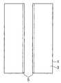
이러한 다광자 흡수를 이용하는 본 실시 형태와 관련되는 레이저 가공의 원 리에 대해서 도 1∼도 6을 이용하여 설명한다. 도 1은 레이저 가공중의 가공 대상물(1)의 평면도이고, 도 2는 도 1에 나타내는 가공 대상물(1)의 II-II선을 따른 단면도이고, 도 3은 레이저 가공 후의 가공 대상물(1)의 평면도이고, 도 4는 도 3에 나타내는 가공 대상물(1)의 IV-IV선을 따른 단면도이고, 도 5는 도 3에 나타내는 가공 대상물(1)의 V-V선을 따른 단면도이고, 도 6은 절단된 가공 대상물(1)의 평면도이다.The principle of laser processing according to the present embodiment using such multiphoton absorption will be described with reference to FIGS. 1 to 6. 1 is a plan view of the
도 1 및 도 2에 나타내듯이, 가공 대상물(1)의 표면(3)에는 절단 예정 라인(5)이 있다. 절단 예정 라인(5)은 직선상으로 뻗은 가상선이다. 본 실시 형태와 관련되는 레이저 가공은, 다광자 흡수가 생기는 조건에서 가공 대상물(1)의 내부에 집광점 P를 맞추어 레이저 광 L을 가공 대상물(1)에 조사하여 개질 영역(7)을 형성한다. 또한, 집광점은 레이저 광 L이 집광한 개소이다.As shown to FIG. 1 and FIG. 2, the cutting
레이저 광 L을 절단 예정 라인(5)을 따라(즉, 화살표 A방향을 따라) 상대적으로 이동시킴으로써, 집광점 P를 절단 예정 라인(5)을 따라 이동시킨다. 이에 의해 도 3∼도 5에 나타내듯이, 개질 영역(7)이 절단 예정 라인(5)을 따라 가공 대상물(1)의 내부에만 형성된다. 본 실시 형태와 관련되는 레이저 가공 방법은, 가공 대상물(1)이 레이저 광 L을 흡수함으로써 가공 대상물(1)을 발열시켜 개질 영역(7)을 형성하는 것은 아니다. 가공 대상물(1)에 레이저 광 L을 투과시키고 가공 대상물(1)의 내부에 다광자 흡수를 발생시켜 개질 영역(7)을 형성하고 있다. 따라서, 가공 대상물(1)의 표면(3)에서는 레이저 광 L이 거의 흡수되지 않기 때문에 가공 대상물(1)의 표면(3)이 용융하는 일은 없다.By moving the laser light L relatively along the cut schedule line 5 (that is, along the arrow A direction), the light collection point P is moved along the
가공 대상물(1)의 절단에 있어서, 절단하는 개소에 기점이 있으면 가공 대상물(1)은 그 기점으로부터 갈라지므로, 도 6에 나타내듯이, 비교적 작은 힘으로 가공 대상물(1)을 절단할 수가 있다. 따라서, 가공 대상물(1)의 표면(3)에 불필요한 갈라짐을 발생시키는 일 없이 가공 대상물(1)의 절단이 가능하게 된다.In the cutting of the
또한, 개질 영역을 기점으로 한 가공 대상물의 절단은 다음의 2가지가 생각될 수 있다. 하나는, 개질 영역 형성 후, 가공 대상물에 인위적인 힘이 인가됨으로써, 개질 영역을 기점으로 하여 가공 대상물이 갈라져 가공 대상물이 절단되는 경우이다. 이것은, 예를 들면 가공 대상물의 두께가 큰 경우의 절단이다. 인위적인 힘이 인가된다는 것은, 예를 들면, 가공 대상물의 절단 예정 라인을 따라 가공 대상물에 휨 응력이나 전단 응력을 가하거나 가공 대상물에 온도차를 줌으로써 열응력을 발생시키거나 하는 것이다. 또 다른 하나는, 개질 영역을 형성함으로써, 개질 영역을 기점으로 하여 가공 대상물의 단면 방향(두께 방향)을 향해 자연스럽게 갈라져 결과적으로 가공 대상물이 절단되는 경우이다. 이것은, 예를 들면 가공 대상물의 두께가 작은 경우 개질 영역이 하나이어도 가능하고, 가공 대상물의 두께가 큰 경우 두께 방향으로 복수의 개질 영역을 형성함으로써 가능하게 된다. 또한, 이 자연스럽게 갈라지는 경우도, 절단하는 개소에 있어서 개질 영역이 형성되어 있지 않은 부분상의 표면까지 갈라짐이 앞질러 가는 일이 없고, 개질 영역을 형성한 부분상의 표면만을 할단(割斷)할 수가 있으므로, 할단을 제어하기 좋게 할 수가 있다. 최근 실리콘 웨이퍼 등의 반도체 웨이퍼의 두께는 얇아지는 경향이 있으므로, 이러한 제어성이 좋은 할단 방법은 대단히 유효하다.In addition, the following two things can be considered as the cutting | disconnection of the process object from the modified area | region. One is a case where an artificial force is applied to an object to be processed after formation of the modified region, whereby the object is split from the modified region as a starting point and the object is cut. This is a cutting | disconnection, for example when the thickness of a process target object is large. An artificial force is applied to generate a thermal stress, for example, by applying a bending stress or a shear stress to a workpiece along a scheduled cutting line of the workpiece or by giving a temperature difference to the workpiece. Another one is a case where the modified region is naturally divided by forming the modified region toward the cross-sectional direction (thickness direction) of the object to be processed as a starting point, and as a result, the object is cut. This can be achieved by, for example, only one modified region when the thickness of the object is small, and by forming a plurality of modified regions in the thickness direction when the thickness of the object is large. In addition, even in the case of this naturally cracking, since the cracking does not go to the surface of the portion on which the modified region is not formed at the cut position, only the surface on the portion on which the modified region is formed can be cut. You can make it easier to control. Since the thickness of semiconductor wafers, such as a silicon wafer, tends to become thin in recent years, the cutting method with such controllability is very effective.
그런데, 본 실시 형태에 있어서 다광자 흡수에 의해 형성되는 개질 영역으로서 다음의 (1)∼(3)이 있다.By the way, in the present embodiment, there are the following (1) to (3) as modified regions formed by multiphoton absorption.
(1) 개질 영역이 하나 또는 복수의 크랙 스폿을 포함한 크랙 영역인 경우(1) When the modified area is a crack area including one or a plurality of crack spots
레이저 광을 가공 대상물(예를 들면, 유리나 LiTaO3로 이루어지는 압전 재료)의 내부에 집광점을 맞추어, 집광점에 있어서의 전기장 강도가 1×10⁸(W/㎠) 이상이고 한편 펄스폭이 1μs 이하인 조건으로 조사한다. 이 펄스폭의 크기는, 다광자 흡수를 생기게 하면서 가공 대상물에 불필요한 손상을 주지 않고, 가공 대상물의 내부에 크랙 영역을 형성할 수 있는 조건이다. 이에 의해 가공 대상물의 내부에는 다광자 흡수에 의한 광학적 손상이라고 하는 현상이 발생한다. 이 광학적 손상에 의해 가공 대상물의 내부에 열왜곡이 야기되고, 이에 의해 가공 대상물의 내부에 크랙 영역이 형성된다. 전기장 강도의 상한치로서는, 예를 들면 1×10¹²(W/㎠)이다. 펄스폭은 예를 들면 1ns∼200ns가 바람직하다. 또한, 다광자 흡수에 의한 크랙 영역의 형성은, 예를 들면, 제45회 레이저 열가공 연구회 논문집(1998년. 12월)의 제23 페이지~제28 페이지의 「고체 레이저 고조파에 의한 유리 기판의 내부 마킹(marking)」에 기재되어 있다.The laser light is focused on the inside of the object to be processed (for example, a piezoelectric material made of glass or LiTaO3 ), and the electric field intensity at the light collecting point is 1 × 10⁸ (W / cm 2) or more, while the pulse width is 1 μs. Investigate on the following conditions. This pulse width is a condition under which a crack region can be formed inside the object to be processed without causing unnecessary damage to the object to be processed while causing multiphoton absorption. As a result, a phenomenon called optical damage due to multiphoton absorption occurs inside the object to be processed. This optical damage causes thermal distortion inside the workpiece, whereby a crack region is formed inside the workpiece. As an upper limit of electric field intensity, it is 1 * 10 <12> (W / cm <2>), for example. The pulse width is preferably 1 ns to 200 ns, for example. In addition, the formation of the crack region by multiphoton absorption is described, for example, in pages 23 to 28 of the 45th Laser Thermal Processing Society Proceedings (December 1998). Internal marking ”.
본 발명자는 전기장 강도와 크랙의 크기와의 관계를 실험에 의해 구하였다. 실험 조건은 다음과 같다.The inventors obtained the relationship between the electric field strength and the size of cracks by experiment. Experimental conditions are as follows.
(A) 가공 대상물 : 파이렉스(등록상표) 유리(두께 700μm, 외경 4인치)(A) Object to be processed : Pyrex (registered trademark) glass (
(B) 레이저(B) laser
광원 : 반도체 레이저 여기 Nd:YAG 레이저Light source : Semiconductor laser excitation Nd : YAG laser
파장 : 1064nmWavelength: 1064nm
레이저 광 스폿(spot) 단면적 : 3.14×10⁻⁸㎠Laser light spot cross section: 3.14 × 10⁻⁸ cm 2
발진 형태 : Q 스위치 펄스Oscillation form : Q switch pulse
반복 주파수 : 100kHzRepetition frequency : 100kHz
펄스폭 : 30nsPulse width : 30ns
출력 : 출력<1mJ/펄스(pulse)Output : Output <1mJ / pulse
레이저 광 품질 : TEM00Laser light quality : TEM00
편광 특성 : 직선 편광Polarization characteristics : Linearly polarized light
(C) 집광용 렌즈(C) condensing lens
레이저 광파장에 대한 투과율 : 60%Transmittance to laser light wavelength: 60%
(D) 가공 대상물이 재치되는 재치대의 이동 속도 : 100mm/초(D) The moving speed of the mounting table on which the object is placed: 100 mm / sec
또한, 레이저 광 품질이 TEM00라는 것은, 집광성이 높고 레이저 광의 파장 정도까지 집광가능을 의미한다.In addition, the laser light quality of TEM00 means that light condensation is high and the light can be collected up to a wavelength of the laser light.
도 7은 상기 실험의 결과를 나타내는 그래프이다. 가로축은 피크파워 밀도이고, 레이저 광이 펄스 레이저 광이므로 전기장 강도는 피크파워 밀도로 나타난다. 세로축은 1 펄스의 레이저 광에 의해 가공 대상물의 내부에 형성된 크랙(crack) 스폿(spot)의 크기를 나타내고 있다. 크랙 스폿의 크기는 크랙 스폿의 형상 중 최대의 길이가 되는 부분의 크기이다. 그래프중의 검은 점으로 나타내는 데이터는 집광 용 렌즈(C)의 배율이 100배, 개구수(NA)가 0.80인 경우이다. 한편, 그래프중의 흰 점으로 나타내는 데이터는 집광용 렌즈(C)의 배율이 50배, 개구수(NA)가 0.55인 경우이다. 피크파워 밀도가 1011(W/㎠) 정도에서는 가공 대상물의 내부에 크랙 스폿이 발생하고, 피크파워 밀도가 크게 됨에 따라 크랙 스폿도 커지는 것을 알 수 있다.7 is a graph showing the results of the experiment. The abscissa is the peak power density, and since the laser light is pulsed laser light, the electric field intensity is represented by the peak power density. The vertical axis represents the size of a crack spot formed inside the object to be processed by one pulse of laser light. The size of the crack spot is the size of the portion of the shape of the crack spot that is the maximum length. Data represented by black dots in the graph is a case where the magnification of the condensing lens C is 100 times and the numerical aperture NA is 0.80. On the other hand, the data represented by the white dots in the graph is a case where the magnification of the condensing lens C is 50 times and the numerical aperture NA is 0.55. It can be seen that when the peak power density is about 1011 (W / cm 2), a crack spot occurs inside the object to be processed, and as the peak power density increases, the crack spot also increases.
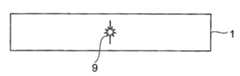
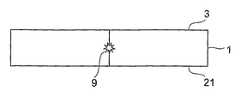
다음에, 크랙 영역 형성에 의한 가공 대상물의 절단의 메카니즘(mechanism)에 대해서 도 8∼도 11을 이용하여 설명한다. 도 8에 나타내듯이, 다광자 흡수가 생기는 조건에서 가공 대상물(1)의 내부에 집광점 P를 맞추어 레이저 광 L을 가공 대상물(1)에 조사하여 절단 예정 라인을 따라 내부에 크랙 영역(9)을 형성한다. 크랙 영역(9)은 하나 또는 복수의 크랙 스폿을 포함한 영역이다. 도 9에 나타내듯이, 크랙 영역(9)을 기점으로 하여 크랙이 한층 더 성장하고, 도 10에 나타내듯이, 크랙이 가공 대상물(1)의 표면(3)과 이면(21)에 도달하고, 도 11에 나타내듯이, 가공 대상물(1)이 갈라짐으로써 가공 대상물(1)이 절단된다. 가공 대상물의 표면과 이면에 도달하는 크랙은 자연스럽게 성장하는 경우도 있고, 가공 대상물에 힘이 인가됨으로써 성장하는 경우도 있다.Next, the mechanism of cutting of the object by crack formation will be described with reference to FIGS. 8 to 11. As shown in FIG. 8, the laser beam L is irradiated to the
(2) 개질 영역이 용융 처리 영역인 경우(2) When the reformed region is a molten processed region
레이저 광을 가공 대상물(예를 들면, 실리콘과 같은 반도체 재료)의 내부에 집광점을 맞추어, 집광점에 있어서의 전기장 강도가 1×10⁸(W/㎠) 이상이고 한편 펄스폭이 1μs 이하인 조건으로 조사한다. 이에 의해 가공 대상물의 내부는 다광자 흡수에 의해 국소적으로 가열된다. 이 가열에 의해 가공 대상물의 내부에 용융 처 리 영역이 형성된다. 용융 처리 영역이라는 것은 일단 용융 후 다시 고체화 한 영역이나, 확실히 용융한 상태의 영역이나, 용융 상태로부터 다시 고체화 하는 상태의 영역이고, 상변화한 영역이나 결정 구조가 변화한 영역이라고 할 수도 있다. 또, 용융 처리 영역이라는 것은 단결정 구조, 비정질 구조, 다결정 구조에 있어서, 어떤 구조가 다른 구조로 변화한 영역이라고 할 수도 있다. 즉, 예를 들면, 단결정 구조로부터 비정질 구조로 변화한 영역, 단결정 구조로부터 다결정 구조로 변화한 영역, 단결정 구조로부터 비정질 구조 및 다결정 구조를 포함하는 구조로 변화한 영역을 의미한다. 가공 대상물이 실리콘 단결정 구조의 경우, 용융 처리 영역은 예를 들면 비정질 실리콘 구조이다. 전기장 강도의 상한치로서는, 예를 들면 1×10¹²(W/㎠)이다. 펄스폭은 예를 들면 1ns∼200ns가 바람직하다.The laser beam is focused on the inside of the object to be processed (for example, a semiconductor material such as silicon) so that the electric field intensity at the light collecting point is 1 × 10⁸ (W / cm 2) or more and the pulse width is 1 μs or less. Investigate with As a result, the inside of the object to be processed is locally heated by multiphoton absorption. This heating forms a molten processed region within the object. The molten processed region may be a region which is once solidified after melting, a region which is surely melted, or a region which is solidified again from a molten state, and may be a region in which a phase change or a crystal structure is changed. The molten processed region may be referred to as a region in which a structure is changed to another structure in a single crystal structure, an amorphous structure, and a polycrystal structure. That is, for example, a region changed from a single crystal structure to an amorphous structure, a region changed from a single crystal structure to a polycrystalline structure, and a region changed from a single crystal structure to a structure including an amorphous structure and a polycrystalline structure. When the object to be processed is a silicon single crystal structure, the molten processed region is, for example, an amorphous silicon structure. As an upper limit of electric field intensity, it is 1 * 10 <12> (W / cm <2>), for example. The pulse width is preferably 1 ns to 200 ns, for example.
본 발명자는 실리콘 웨이퍼의 내부에서 용융 처리 영역이 형성되는 것을 실험에 의해 확인했다. 실험 조건은 다음과 같다.The inventors confirmed by experiment that a molten processed region was formed inside a silicon wafer. Experimental conditions are as follows.
(A) 가공 대상물 : 실리콘 웨이퍼(두께 350μm, 외경 4인치)(A) Object to be processed : Silicon wafer (thickness 350 μm, outer diameter 4 inches)
(B) 레이저(B) laser
광원 : 반도체 레이저 여기 Nd:YAG 레이저Light source : Semiconductor laser excitation Nd : YAG laser
파장 : 1064nmWavelength: 1064nm
레이저 광 스폿(spot) 단면적 : 3.14×10⁻⁸㎠Laser light spot cross section: 3.14 × 10⁻⁸ cm 2
발진 형태 : Q 스위치 펄스Oscillation form : Q switch pulse
반복 주파수 : 100kHzRepetition frequency : 100kHz
펄스폭 : 30nsPulse width : 30ns
출력 : 20μJ/펄스(pulse)Output : 20μJ / pulse
레이저 광 품질 : TEM00Laser light quality : TEM00
편광 특성 : 직선 편광Polarization characteristic : Linear polarization
(C) 집광용 렌즈(C) condensing lens
배율 : 50배Magnification : 50 times
N.A. : 0.55N.A. : 0.55
레이저 광파장에 대한 투과율 : 60%Transmittance to laser light wavelength: 60%
(D) 가공 대상물이 재치되는 재치대의 이동 속도 : 100mm/초(D) The moving speed of the mounting table on which the object is placed: 100 mm / sec
도 12는 상기 조건에서의 레이저 가공에 의해 절단된 실리콘 웨이퍼의 일부에 있어서의 단면의 사진을 나타낸 도이다. 실리콘 웨이퍼(11)의 내부에 용융 처리 영역(13)이 형성되어 있다. 또한, 상기 조건에 의해 형성된 용융 처리 영역(13)의 두께 방향의 크기는 100μm 정도이다.It is a figure which shows the photograph of the cross section in a part of silicon wafer cut | disconnected by the laser processing on the said conditions. The molten processed
용융 처리 영역(13)이 다광자 흡수에 의해 형성된 것을 설명한다. 도 13은 레이저 광의 파장과 실리콘 기판의 내부의 투과율과의 관계를 나타내는 그래프이다. 다만, 실리콘 기판의 표면측과 이면측 각각의 반사 성분을 제거하고, 내부만의 투과율을 나타내고 있다. 실리콘 기판의 두께 t가 50μm, 100μm, 200μm, 500μm, 1000μm의 각각에 대해서 상기 관계를 나타냈다.It will be described that the molten processed
예를 들면, Nd:YAG 레이저의 파장인 1064nm에 있어서, 실리콘 기판의 두께 가 500μm 이하의 경우, 실리콘 기판의 내부에서는 레이저 광이 80% 이상 투과하는 것을 알 수 있다. 도 12에 나타내는 실리콘 웨이퍼(11)의 두께는 350μm이므로, 다광자 흡수에 의한 용융 처리 영역(13)은 실리콘 웨이퍼의 중심 부근, 즉 표면으로부터 175μm의 부분에 형성된다. 이 경우의 투과율은, 두께 200μm의 실리콘 웨이퍼를 참고로 하면, 90% 이상이므로, 레이저 광이 실리콘 웨이퍼(11)의 내부에서 흡수되는 것은 아주 적고 거의가 투과한다. 이는 실리콘 웨이퍼(11)의 내부에서 레이저 광이 흡수되어, 용융 처리 영역(13)이 실리콘 웨이퍼(11)의 내부에 형성(즉, 레이저 광에 의한 통상의 가열로 용융 처리 영역이 형성)된 것이 아니고, 용융 처리 영역(13)이 다광자 흡수에 의해 형성된 것을 의미한다. 다광자 흡수에 의한 용융 처리 영역의 형성은, 예를 들면, 용접 학회 전국 대회 강연 개요 제66집(2000년 4월)의 제72 페이지~제73 페이지의 「피코초(pico-second) 펄스 레이저에 의한 실리콘의 가공 특성 평가」에 기재되어 있다.For example, in 1064 nm which is a wavelength of Nd: YAG laser, when the thickness of a silicon substrate is 500 micrometers or less, it turns out that 80% or more of laser beam transmits inside a silicon substrate. Since the thickness of the
또한, 실리콘 웨이퍼는, 용융 처리 영역을 기점으로 하여 단면 방향을 향해 갈라짐을 발생시키고, 그 갈라짐이 실리콘 웨이퍼의 표면과 이면에 도달함으로써 결과적으로 절단된다. 실리콘 웨이퍼의 표면과 이면에 도달하는 이 갈라짐은 자연스럽게 성장하는 경우도 있고, 가공 대상물에 힘이 인가됨으로써 성장하는 경우도 있다. 또한, 용융 처리 영역으로부터 웨이퍼의 표면과 이면에 갈라짐이 자연스럽게 성장하는 경우에 있어서, 용융 처리 영역이 용융의 상태로부터 갈라짐이 성장하든지, 혹은 용융의 상태로부터 다시 고체화 할 때에 갈라짐이 성장하는 경우의 어느 것이나 존재한다. 다만, 이러한 경우도 용융 처리 영역은 웨이퍼의 내부에만 형성 되어 절단 후의 절단면은 도 12와 같이 내부에만 용융 처리 영역이 형성되어 있다. 가공 대상물의 내부에 용융 처리 영역을 형성하는 경우, 할단(割斷)시 절단 예정 라인으로부터 벗어난 불필요한 갈라짐이 생기기 어렵기 때문에 할단 제어가 용이하게 된다.Further, the silicon wafer is cracked in the cross-sectional direction starting from the molten processed region, and the crack is cut off as a result of reaching the front and back surfaces of the silicon wafer. This crack reaching the front and back of the silicon wafer may grow naturally, or may grow when a force is applied to the object to be processed. In the case where the cracks naturally grow from the molten processed region to the front and back surfaces of the wafer, either the cracks grow from the molten state or the cracks grow when the solidified from the molten state again. Is present. However, even in such a case, the molten processed region is formed only in the inside of the wafer, and the cut surface after cutting is formed only in the inside as shown in FIG. 12. In the case where the molten processed region is formed inside the object to be processed, the splitting control becomes easy because unnecessary splitting off the cutting scheduled line during the cutting is unlikely to occur.
(3) 개질 영역이 굴절률 변화 영역인 경우(3) the modified region is a refractive index change region
레이저 광을 가공 대상물(예를 들면, 유리)의 내부에 집광점을 맞추어, 집광점에 있어서의 전기장 강도가 1×10⁸(W/㎠) 이상이고 한편 펄스폭이 1ns 이하인 조건으로 조사한다. 펄스폭을 매우 짧게 하여 다광자 흡수를 가공 대상물의 내부에 일으키게 하면, 다광자 흡수에 의한 에너지가 열에너지로 바뀌지 않고, 가공 대상물의 내부에는 이온 가수 변화, 결정화 또는 분극 배향 등의 영속적인 구조 변화가 야기되어 굴절률 변화 영역이 형성된다. 전기장 강도의 상한치로서는, 예를 들면 1×10¹²(W/㎠)이다. 펄스폭은 예를 들면 1ns 이하가 바람직하고, 1ps 이하가 한층 더 바람직하다. 다광자 흡수에 의한 굴절률 변화 영역의 형성은, 예를 들면, 제42회 레이저 열가공 연구회 논문집(1997년. 11월)의 제105페이지~제111페이지의 「펨토초(femto-second) 레이저 조사에 의한 유리 내부에의 광 야기 구조 형성」에 기재되어 있다.The laser beam is focused on the inside of the object to be processed (for example, glass), and irradiated under the condition that the electric field intensity at the focusing point is 1 × 10⁸ (W / cm 2) or more and the pulse width is 1 ns or less. When the pulse width is made very short to cause multiphoton absorption inside the workpiece, the energy due to multiphoton absorption does not change into thermal energy, and permanent structure changes such as ion valence change, crystallization, or polarization orientation do not occur inside the workpiece. Is caused to form a refractive index change region. As an upper limit of electric field intensity, it is 1 * 10 <12> (W / cm <2>), for example. For example, the pulse width is preferably 1 ns or less, and more preferably 1 ps or less. Formation of the refractive index change region by multiphoton absorption is described, for example, in the femto-second laser irradiation on
이상, 다광자 흡수에 의해 형성되는 개질 영역으로서 (1)∼(3)의 경우를 설명했지만, 웨이퍼 형상의 가공 대상물의 결정 구조나 그 벽개성(劈開性) 등을 고려하여 절단 기점 영역을 다음과 같이 형성하면, 그 절단 기점 영역을 기점으로 하여 한층 더 작은 힘으로, 또한, 정밀도 좋게 가공 대상물을 절단하는 것이 가능하게 된다.As mentioned above, although the case of (1)-(3) was demonstrated as a modified area | region formed by multiphoton absorption, a cutting starting point area | region is considered next in consideration of the crystal structure of a wafer-like process object, its cleavage property, etc. When formed as described above, it becomes possible to cut the object to be processed more precisely and with a smaller force with the cutting starting point region as a starting point.
즉, 실리콘 등의 다이아몬드 구조의 단결정 반도체로 이루어지는 기판의 경우는, (111)면(제1 벽개면)이나 (110)면(제2 벽개면)을 따른 방향으로 절단 기점 영역을 형성하는 것이 바람직하다. 또, GaAs 등의 섬아연광형 구조의 III-V족 화합물 반도체로 이루어지는 기판의 경우는, (110)면을 따른 방향으로 절단 기점 영역을 형성하는 것이 바람직하다. 또한, 사파이어(Al2O3) 등의 육방정계의 결정 구조를 가지는 기판의 경우는, (0001)면(C면)을 주면으로 하여 (1120)면(A면) 혹은 (1100)면(M면)을 따른 방향으로 절단 기점 영역을 형성하는 것이 바람직하다.That is, in the case of a substrate made of a single crystal semiconductor having a diamond structure such as silicon, it is preferable to form a starting point region for cutting in the direction along the (111) plane (first cleaved plane) or the (110) plane (second cleaved plane). Moreover, in the case of the board | substrate which consists of group III-V compound semiconductors of a galvanic structure, such as GaAs, it is preferable to form a cutting origin region in the direction along the (110) plane. In the case of a substrate having a hexagonal crystal structure such as sapphire (Al2 O3 ), the (0001) plane (C plane) is used as the main plane (1120) plane (A plane) or (1100) plane (M). It is preferable to form the starting point region for cutting in the direction along the plane).
또한, 상술한 절단 기점 영역을 형성해야 할 방향(예를 들면, 단결정 실리콘 기판에 있어서의 (111)면을 따른 방향), 혹은 절단 기점 영역을 형성해야 할 방향으로 직교하는 방향을 따라 기판에 오리엔테이션(orientation) 플랫(flat)을 형성하면, 그 오리엔테이션 플랫을 기준으로 함으로써, 절단 기점 영역을 형성해야 할 방향을 따른 절단 기점 영역을 용이하고 한편 정확하게 기판에 형성하는 것이 가능하게 된다.Further, orientation is performed on the substrate along the direction orthogonal to the direction in which the above-mentioned cutting origin region should be formed (for example, the direction along the (111) plane in the single crystal silicon substrate) or the direction in which the cutting origin region should be formed. By forming the orientation flat, it is possible to easily and accurately form the cutting origin region along the direction in which the cutting origin region is to be formed on the substrate by referring to the orientation flat.
이하, 실시예에 의해 본 발명에 대해서 보다 구체적으로 설명한다.Hereinafter, an Example demonstrates this invention more concretely.
[실시예 1]EXAMPLE 1
본 발명의 실시예 1에 대해서 설명한다. 실시예 1과 관련되는 레이저 가공 방법은, 가공 대상물의 내부에 다광자 흡수에 의한 개질 영역을 형성하는 개질 영 역 형성 공정과 가공 대상물이 절단되는 개소에 스트레스를 생기게 하는 스트레스 공정을 구비하고 있다.
실시예 1과 관련되는 레이저 가공 장치에 대해서 설명한다. 도 14는 개질 영역 형성 공정에서 이용되는 레이저 가공 장치(100)의 개략 구성도이다. 도시하듯이 레이저 가공 장치(100)는, 레이저 광 L을 발생하는 레이저 광원(101)과, 레이저 광 L의 출력이나 펄스폭 등을 조절하기 위해서 레이저 광원(101)을 제어하는 레이저 광원 제어부(102)와, 레이저 광 L의 반사 기능을 가지고 한편 레이저 광 L의 광축의 방향을 90° 바꾸도록 배치된 다이크로익미러(dichroic mirror)(103)와, 다이크로익 미러(103)로 반사된 레이저 광 L을 집광하는 집광용 렌즈(105)와, 집광용 렌즈(105)로 집광된 레이저 광 L이 조사되는 가공 대상물(1)이 재치되는 재치대(107)와, 재치대(107)를 X축 방향으로 이동시키기 위한 X축 스테이지(109)와, 재치대(107)를 X축 방향에 직교하는 Y축 방향으로 이동시키기 위한 Y축 스테이지(111)와, 재치대(107)를 X축 및 Y축 방향에 직교하는 Z축 방향으로 이동시키기 위한 Z축 스테이지(113)와, 이들 3개의 스테이지(109, 111, 113)의 이동을 제어하는 스테이지 제어부(115)를 구비한다. 또한, 실시예 1에 있어서, 가공 대상물(1)은 파이렉스(등록상표) 유리 웨이퍼이다.The laser processing apparatus which concerns on Example 1 is demonstrated. 14 is a schematic configuration diagram of a
Z축 방향은 가공 대상물(1)의 표면(3)과 직교하는 방향이므로 가공 대상물(1)로 입사하는 레이저 광 L의 초점심도의 방향이 된다. 따라서, Z축 스테이지(113)를 Z축 방향으로 이동시킴으로써, 가공 대상물(1)의 내부에 레이저 광 L의 집광점 P를 맞출 수가 있다. 또, 이 집광점 P의 X(Y)축 방향의 이동은 가공 대상물 (1)을 X(Y)축 스테이지(109)(111)에 의해 X(Y)축 방향으로 이동시킴으로써 행한다.Since the Z-axis direction is a direction orthogonal to the
레이저 광원(101)은 펄스 레이저 광을 발생하는 Nd:YAG 레이저이다. 레이저 광원(101)에 이용할 수가 있는 레이저로서, 이외에 Nd:YVO4 레이저나 Nd:YLF 레이저가 있다. 레이저 광원은 크랙 영역, 용융 처리 영역을 형성하는 경우, 전술의 레이저 광원을 이용하는 것이 적합하고, 굴절률 변화 영역을 형성하는 경우, 티탄 사파이어 레이저를 이용하는 것이 매우 적합하다. 실시예 1에서는 가공 대상물(1)의 가공에 펄스 레이저 광을 이용하고 있지만, 다광자 흡수를 일으키게 할 수가 있다면 연속파 레이저 광이어도 좋다.The
레이저 가공 장치(100)는 또한 재치대(107)에 재치된 가공 대상물(1)을 가시광선에 의해 조명하기 위해서 가시광선을 발생하는 관찰용 광원(117)과, 다이크로익 미러(103) 및 집광용 렌즈(105)와 동일 광축 상에 배치된 가시광용의 빔 분할기(119)를 구비한다. 빔 분할기(119)와 집광용 렌즈(105)의 사이에 다이크로익 미러(103)가 배치되어 있다. 빔 분할기(119)는 가시광선의 약 반을 반사하고 나머지의 반을 투과하는 기능을 가지고 한편 가시광선의 광축의 방향을 90° 바꾸도록 배치되어 있다. 관찰용 광원(117)으로부터 발생한 가시광선은 빔 분할기(119)로 약 반이 반사되고, 이 반사된 가시광선이 다이크로익 미러(103) 및 집광용 렌즈(105)를 투과하고, 가공 대상물(1)의 절단 예정 라인(5) 등을 포함한 표면(3)을 조명한다.The
레이저 가공 장치(100)는 또한 빔 분할기(119), 다이크로익 미러(103) 및 집광용 렌즈(105)와 동일 광축 상에 배치된 촬상 소자(121) 및 결상 렌즈(123)를 구 비한다. 촬상 소자(121)로서는 예를 들면 CCD(charge-coupled device) 카메라가 있다. 절단 예정 라인(5) 등을 포함한 표면(3)을 조명한 가시광선의 반사광은, 집광용 렌즈(105), 다이크로익 미러(103), 빔 분할기(119)를 투과하고, 결상 렌즈(123)로 결상되고 촬상 소자(121)로 촬상되어 촬상 데이터로 된다.The
레이저 가공 장치(100)는 또한 촬상 소자(121)로부터 출력된 촬상 데이터가 입력되는 촬상 데이터 처리부(125)와, 레이저 가공 장치(100) 전체를 제어하는 전체 제어부(127)와, 모니터(129)를 구비한다. 촬상 데이터 처리부(125)는 촬상 데이터를 기초로 하여 관찰용 광원(117)에서 발생한 가시광의 초점을 표면(3) 상에 맞추기 위한 초점 데이터를 연산한다. 이 초점 데이터를 기초로 하여 스테이지 제어부(115)가 Z축 스테이지(113)를 이동 제어함으로써, 가시광의 초점이 표면(3)에 맞도록 한다. 따라서, 촬상 데이터 처리부(125)는 오토포커스(auto-focus) 유닛(unit)으로서 기능한다. 또한, 가시광의 초점은 레이저 광 L의 집광점에 일치하고 있다. 또, 촬상 데이터 처리부(125)는 촬상 데이터를 기초로 하여 표면(3)의 확대 화상 등의 화상 데이터를 연산한다. 이 화상 데이터는 전체 제어부(127)에 보내어지고, 전체 제어부에서 각종 처리가 되어, 모니터(129)에 보내어진다. 이에 의해 모니터(129)에 확대 화상 등이 표시된다.The
전체 제어부(127)에는, 스테이지 제어부(115)로부터의 데이터, 촬상 데이터 처리부(125)로부터의 화상 데이터 등이 입력되고, 이러한 데이터도 기초로 하여 레이저 광원 제어부(102), 관찰용 광원(117) 및 스테이지 제어부(115)를 제어함으로써, 레이저 가공 장치(100) 전체를 제어한다. 따라서, 전체 제어부(127)는 컴퓨터 유닛으로서 기능한다.Data from the
또, 스트레스 공정에서 이용되는 흡수성 레이저 조사 장치는, 상술한 레이저 가공 장치(100)에 대해서, 레이저 광원과 다이크로익 미러만이 다른 구성을 취하고 있다. 흡수성 레이저 조사 장치의 레이저 광원으로서는, 연속파 레이저 광을 발생하는 파장이 10.6μm의 CO2 레이저를 이용하였다. 파이렉스(등록상표) 유리 웨이퍼인 가공 대상물(1)에 대해서 흡수성을 가지기 때문이다. 이하, 이 레이저 광원에서 발생하는 레이저 광을 「흡수성 레이저 광」이라고 한다. 또한, 빔 품질은 TEM00이고, 편광 특성은 직선 편광이다. 또, 가공 대상물(1)을 가열하고 또한 용융시키지 않을 정도의 강도로 하기 위해서 이 레이저 광원의 출력은 10W 이하로 되어 있다. 흡수성 레이저 조사 장치의 다이크로익 미러는 흡수성 레이저 광의 반사 기능을 가지고 한편 흡수성 레이저 광의 광축의 방향을 90° 바꾸도록 배치되어 있다.The absorbent laser irradiation apparatus used in the stress step has a configuration in which only the laser light source and the dichroic mirror differ from the
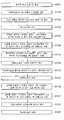
다음에, 도 14 및 도 15를 참조하여 실시예 1과 관련되는 레이저 가공 방법에 대해서 설명한다. 도 15는 레이저 가공 방법을 설명하기 위한 플로차트이다.Next, the laser processing method concerning Example 1 is demonstrated with reference to FIG. 14 and FIG. 15 is a flowchart for explaining a laser processing method.
우선, 가공 대상물(1)의 광흡수 특성을 도시하지 않는 분광 광도계 등에 의해 측정한다. 이 측정 결과에 기초하여 가공 대상물(1)에 대해서 투명한 파장 또는 흡수가 적은 파장의 레이저 광 L을 발생하는 레이저 광원(101)과 가공 대상물(1)에 대해서 흡수성 파장의 흡수성 레이저 광을 발생하는 레이저 광원을 선정하고, 각각 레이저 가공 장치(100)와 흡수성 레이저 조사 장치에 설정된다(S101). 다음에, 가공 대상물(1)의 두께를 측정한다. 두께의 측정 결과 및 가공 대상물(1)의 굴절률을 기초로 하여, 레이저 가공 장치(100)에 있어서의 가공 대상물(1)의 Z축 방향의 이동량을 결정한다(S103). 이는 레이저 광 L의 집광점 P를 가공 대상물(1)의 내부에 위치시키기 위해서, 가공 대상물(1)의 표면(3)에 위치하는 레이저 광 L의 집광점을 기준으로 한 가공 대상물(1)의 Z축 방향의 이동량이다. 이 이동량은 개질 영역 형성 공정에서 이용되는 레이저 가공 장치(100)의 전체 제어부(127)에 입력된다.First, the light absorption characteristic of the
가공 대상물(1)을 레이저 가공 장치(100)의 재치대(107)에 재치한다(S104). 그리고, 관찰용 광원(117)으로부터 가시광을 발생시켜 가공 대상물(1)을 조명한다(S105). 조명된 절단 예정 라인(5)을 포함한 가공 대상물(1)의 표면(3)을 촬상 소자(121)에 의해 촬상한다. 이 촬상 데이터는 촬상 데이터 처리부(125)에 보내어진다. 이 촬상 데이터에 기초하여 촬상 데이터 처리부(125)는 관찰용 광원(117)의 가시광의 초점이 표면(3)에 위치할 것 같은 초점 데이터를 연산한다(S107).The
이 초점 데이터는 스테이지 제어부(115)에 보내어진다. 스테이지 제어부(115)는 이 초점 데이터를 기초로 하여 Z축 스테이지(113)를 Z축 방향으로 이동시킨다(S109). 이에 의해 관찰용 광원(117)의 가시광의 초점이 표면(3)에 위치한다. 또한, 촬상 데이터 처리부(125)는 촬상 데이터에 기초하여 절단 예정 라인(5)을 포함한 가공 대상물(1)의 표면(3)의 확대 화상 데이터를 연산한다. 이 확대 화상 데이터는 전체 제어부(127)를 통해 모니터(129)에 보내어지고, 이에 의해 모니터(129)로 절단 예정 라인(5) 부근의 확대 화상이 표시된다.This focus data is sent to the
전체 제어부(127)에는 미리 단계 S103에서 결정된 이동량 데이터가 입력되어 있고, 이 이동량 데이터가 스테이지 제어부(115)에 보내어진다. 스테이지 제어부 (115)는 이 이동량 데이터에 기초하여 레이저 광 L의 집광점 P가 가공 대상물(1)의 내부가 되는 위치에, Z축 스테이지(113)에 의해 가공 대상물(1)을 Z축 방향으로 이동시킨다(S111).The movement amount data determined in step S103 is input to the
다음에, 레이저 광원(101)으로부터 레이저 광 L을 발생시켜, 레이저 광 L을 가공 대상물(1)의 표면(3)의 절단 예정 라인(5)에 조사한다. 도 16은 개질 영역 형성 공정에 있어서 레이저 가공중의 크랙 영역(9)을 포함한 가공 대상물(1)의 단면도이다. 도시하듯이 레이저 광 L의 집광점 P는 가공 대상물(1)의 내부에 위치하고 있으므로, 크랙 영역(9)은 가공 대상물(1)의 내부에만 형성된다. 그리고, 절단 예정 라인(5)을 따르도록 X축 스테이지(109)나 Y축 스테이지(111)를 이동시켜, 크랙 영역(9)을 절단 예정 라인(5)을 따르도록 가공 대상물(1)의 내부에 형성한다(S113).Next, the laser light L is generated from the
레이저 가공 장치(100)에 의해 개질 영역을 형성한 후, 가공 대상물(1)을 흡수성 레이저 조사 장치의 재치대(107)로 반송하여 재치한다(S115). 개질 영역 형성 공정에 있어서의 크랙 영역(9)은 가공 대상물(1)의 내부에만 형성되기 때문에, 가공 대상물(1)은 뿔뿔이 흩어지지 않게 되어 가공 대상물(1)을 용이하게 반송할 수가 있다.After the modified region is formed by the
그리고, 단계 117에 있어서 가공 대상물(1)을 조명하고, 단계 119에 있어서 관찰용 광원의 가시광의 초점이 가공 대상물(1)의 표면(3)에 위치할 것 같은 초점 데이터를 연산하고, 단계 121에 있어서 상기 초점이 가공 대상물(1)의 표면(3)에 위치하도록 가공 대상물(1)을 Z축 방향으로 이동하고, 이에 의해 흡수성 레이저 광 의 집광점이 가공 대상물(1)의 표면(3)에 합쳐진다. 또한, 이러한 단계 117, 단계 119, 단계 121에 있어서의 동작의 자세한 것은, 상술한 레이저 가공 장치(100)에 있어서의 단계 105, 단계 107, 단계 109와 각각 같다.Then, in
다음에, 흡수성 레이저 조사 장치의 레이저 광원으로부터 흡수성 레이저 광을 발생시켜, 흡수성 레이저 광을 가공 대상물(1)의 표면(3)의 절단 예정 라인(5)에 조사한다. 또한, 이 조사는 절단 예정 라인(5) 근방에의 조사이어도 좋다. 그리고, 절단 예정 라인(5)을 따르도록 흡수성 레이저 조사 장치의 X축 스테이지나 Y축 스테이지를 이동시켜, 절단 예정 라인(5)을 따라 가공 대상물(1)을 가열함으로써, 절단 예정 라인(5)을 따라 가공 대상물(1)이 절단되는 개소에 온도차에 의한 열응력 등의 스트레스를 생기게 한다(S123). 이때 흡수성 레이저의 강도는 가공 대상물(1)을 가열하고 또한 용융시키지 않을 정도이기 때문에 가공 대상물의 표면이 용융하는 일은 없다.Next, absorbing laser light is generated from the laser light source of the absorbing laser irradiation apparatus, and the absorbing laser light is irradiated to the cutting scheduled
도 17은 스트레스 공정에 있어서 레이저 가공중의 크랙 영역(9)을 포함한 가공 대상물(1)의 단면도이다. 도시하듯이 흡수성 레이저 광의 조사에 의해, 크랙 영역(9)을 기점으로 하여 크랙이 한층 더 성장하여 크랙이 가공 대상물(1)의 표면(3)과 이면(21)에 도달하고, 가공 대상물(1)에 절단면(10)이 형성되고 가공 대상물(1)이 절단된다(S125). 이에 의해 가공 대상물(1)을 실리콘 칩으로 분할한다.FIG. 17: is sectional drawing of the
또한, 실시예 1에 있어서는, 개질 영역으로서 크랙 영역이 형성되는 경우에 대해서 설명하였지만, 개질 영역으로서 상술한 것 같은 용융 처리 영역이나 굴절률 변화 영역이 형성되는 경우에 대해서도 마찬가지이고, 흡수성 레이저 광의 조사에 의해 스트레스를 생기게 하여 용융 처리 영역이나 굴절률 변화 영역을 기점으로 하여 크랙을 발생, 성장시켜 가공 대상물을 절단할 수가 있다.In addition, in Example 1, although the case where the crack area | region was formed as a modified area was demonstrated, the same also applies to the case where the above-mentioned melt processing area | region and refractive index change area | region are formed as a modified area | region, and it is applied to irradiation of an absorptive laser light. By generating stress, cracks can be generated and grown starting from the molten processed region or the refractive index change region to cut the object to be processed.
또, 가공 대상물의 두께가 큰 경우 등에서, 스트레스 공정에 의해 개질 영역을 기점으로서 성장한 크랙이 가공 대상물의 표면과 이면에 도달하지 않는 경우이어도, 휨 응력이나 전단 응력 등의 인위적인 힘을 인가함으로써 가공 대상물을 갈라서 절단할 수가 있다. 이 인위적인 힘은 보다 작은 힘으로 충분하기 때문에, 가공 대상물의 표면에 절단 예정 라인으로부터 벗어난 불필요한 갈라짐이 발생하는 것을 방지할 수가 있다.Further, even when the thickness of the object to be processed is large, even if the cracks grown from the modified region by the stress process do not reach the front and back surfaces of the object, the artificial object is applied by applying an artificial force such as bending stress or shear stress. You can cut and cut. Since this artificial force is sufficient with a smaller force, it can prevent that the unnecessary split | deviation from the cutting plan line arises on the surface of a to-be-processed object.
실시예 1의 효과를 설명한다. 이에 의하면 개질 영역 형성 공정에 있어서, 다광자 흡수를 일으키게 하는 조건으로 한편 가공 대상물(1)의 내부에 집광점 P를 맞추어, 펄스 레이저 광 L을 절단 예정 라인(5)에 조사하고 있다. 그리고, X축 스테이지(109)나 Y축 스테이지(111)를 이동시킴으로써, 집광점 P를 절단 예정 라인(5)을 따라 이동시키고 있다. 이에 의해 개질 영역(예를 들면, 크랙 영역, 용융 처리 영역, 굴절률 변화 영역)을 절단 예정 라인(5)을 따르도록 가공 대상물(1)의 내부에 형성하고 있다. 가공 대상물의 절단하는 개소에 어떠한 기점이 있으면, 가공 대상물을 비교적 작은 힘으로 나누어 절단할 수가 있다. 실시예 1에 의하면, 스트레스 공정에 있어서, 가공 대상물(1)에 절단 예정 라인(5)을 따라 흡수성 레이저 광을 조사하여, 온도차에 의한 열응력 등의 스트레스를 생기게 하고 있다. 따라서, 온도차에 의한 열응력 등의 스트레스라고 하는 비교적 작은 힘으로 가공 대상물(1)을 절단할 수가 있다. 이에 의해 가공 대상물(1)의 표면(3)에 절단 예정 라인(5)으로부터 벗어난 불필요한 갈라짐을 발생시키는 일 없이 가공 대상물(1)을 절단할 수가 있다.The effect of Example 1 is demonstrated. According to this, in the modification area | region formation process, the pulse laser light L is irradiated to the cutting |
또, 실시예 1에 의하면, 개질 영역 형성 공정에 있어서는, 가공 대상물(1)에 다광자 흡수를 일으키게 하는 조건으로 한편 가공 대상물(1)의 내부에 집광점 P를 맞추어 펄스 레이저 광 L을 조사하고 있기 때문에, 펄스 레이저 광 L은 가공 대상물(1)을 투과하고, 가공 대상물(1)의 표면(3)에서는 펄스 레이저 광 L이 거의 흡수되지 않는다. 또, 스트레스 공정에 있어서는, 흡수성 레이저 광의 강도는 가공 대상물(1)을 가열하고 또한 용융시키지 않을 정도이다. 따라서, 레이저 광의 조사가 원인으로 표면(3)이 용융 등의 손상을 받는 일은 없다.In addition, according to Example 1, in the modified region formation process, pulse laser light L is irradiated with the condensing point P inside the
이상 설명한 것처럼 실시예 1에 의하면, 가공 대상물(1)의 표면(3)에 절단 예정 라인(5)으로부터 벗어난 불필요한 갈라짐이나 용융이 생기는 일 없이, 가공 대상물(1)을 절단할 수가 있다. 따라서, 가공 대상물(1)이 예를 들면 반도체 웨이퍼인 경우, 반도체 칩에 절단 예정 라인으로부터 벗어난 불필요한 갈라짐이나 용융이 생기는 일 없이, 반도체 칩을 반도체 웨이퍼로부터 잘라낼 수 있다. 표면에 전극 패턴이 형성되어 있는 가공 대상물이나, 압전소자 웨이퍼나 액정 등의 표시 장치가 형성된 유리 기판과 같이 표면에 전자 디바이스가 형성되어 있는 가공 대상물에 대해서도 마찬가지이다. 따라서, 실시예 1에 의하면, 가공 대상물을 절단함으로써 제작되는 제품(예를 들면, 반도체 칩, 압전 디바이스 칩, 액정 등의 표시 장치)의 제품 수율을 향상시킬 수가 있다.As described above, according to the first embodiment, the
또, 실시예 1에 의하면, 가공 대상물(1)의 표면(3)의 절단 예정 라인(5)은 용융하지 않기 때문에, 절단 예정 라인(5)의 폭(이 폭은, 예를 들면 반도체 웨이퍼의 경우, 반도체 칩이 되는 영역끼리의 간격이다.)을 작게 할 수 있다. 이에 의해 한 장의 가공 대상물(1)로부터 제작되는 제품의 수가 증가해 제품의 생산성을 향상시킬 수가 있다.In addition, according to Example 1, since the cutting scheduled
또, 실시예 1에 의하면, 가공 대상물(1)의 절단 가공에 레이저 광을 이용하므로, 다이아몬드 컷터(cutter)를 이용한 다이싱((dicing)보다 복잡한 가공이 가능하게 된다. 예를 들면, 도 18에 나타내듯이, 절단 예정 라인(5)이 복잡한 형상이어도 절단 가공이 가능하게 된다.Moreover, according to Example 1, since laser light is used for the cutting of the
[실시예 2]EXAMPLE 2
본 발명의 실시예 2에 대해서 설명한다. 또한, 도 20∼도 23은 도 19에 나타내는 가공 대상물(1)의 XX-XX선을 따른 부분 단면도이다.Embodiment 2 of the present invention will be described. 20 to 23 are partial cross-sectional views along the line XX-XX of the
도 19 및 도 20에 나타내듯이, 가공 대상물(1)의 이면(21)으로 확장 가능한 확장 필름(보유부재)(19)을 붙이고, 이 확장 필름(19)의 표면(19a) 상에 가공 대상물(1)을 고정한다. 확장 필름(19)은, 그 외주부분이 링 형상의 필름 고정 프레임(20)에 붙여져, 이 필름 고정 프레임(20)에 고정되어 있다. 또한, 이 가공 대상물(1)은 두께 100μm의 실리콘 웨이퍼이다.19 and 20, an expandable film (holding member) 19 that is expandable to the
이와 같이, 가공 대상물(1), 확장 필름(19) 및 필름 고정 프레임(20)으로 이루어지는 유닛 U를, 예를 들면 상술의 레이저 가공 장치(100)의 재치대(107) 상에, 가공 대상물(1)의 표면(3) 측이 집광용 렌즈(105)로 대면하도록 재치한다. 그리고, 압력부재(107a)에 의해 필름 고정 프레임(20)을 재치대(107)에 고정함과 동시에, 확장 필름(19)을 재치대(107)에 진공 흡착한다.Thus, the unit U which consists of the
이어서, 도 19에 나타내듯이, 가공 대상물(1)의 오리엔테이션 플랫(16)에 평행한 방향과 수직인 방향에 연재(延在)하는 절단 예정 라인(5)을 격자상으로 설정한다. 이 절단 예정 라인은 웨이퍼 상에 형성되어 있는 회로 소자나 수광면 등의 기능 소자로 이루어지는 디바이스 형성면(700)의 사이에 설정되어 있다. 또, 도면에서는 간략하게 디바이스 형성면(700)은 일부에만 기재하고 있다.Next, as shown in FIG. 19, the cutting
그리고, 도 20에 나타내듯이, 가공 대상물(1)의 내부에 집광점 P1을 맞추어 레이저 광 L1을 조사하고, 그 집광점 P1을 절단 예정 라인(5)을 따라 이동시킴으로써 가공 대상물(1)의 내부에 개질 영역(7)을 형성한다. 이 개질 영역(7)에 의해, 가공 대상물(1)의 표면(레이저 광 입사면)(3)으로부터 소정 거리 내측에 절단 기점 영역(8)이 절단 예정 라인(5)을 따라 형성된다. 또한, 가공 대상물(1)이 실리콘 웨이퍼이기 때문에 개질 영역(7)으로서는 용융 처리 영역이 형성된다.Then, as shown in FIG. 20, the laser beam L1 is irradiated with the light collecting point P1 inside the
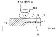
이어서, 도 21에 나타내듯이, 가공 대상물(1)의 표면(3)에 집광점 P2를 맞추어, 가공 대상물(1)에 대해서 흡수성을 가지는 레이저 광 L2를 조사하고, 그 집광점 P2를 절단 예정 라인(5)을 따라 이동시킨다. 이 레이저 광 L2의 조사에 의해, 절단 기점 영역(8)을 기점으로서 갈라짐(24)이 발생하고, 이 갈라짐(24)이 가공 대상물(1)의 표면(3)과 이면(21)에 도달한다. 이에 의해 가공 대상물(1)은 절단 예정 라인(5)을 따라 복수의 칩(25)으로 분할된다.Next, as shown in FIG. 21, the condensing point P2 is matched to the
이러한 갈라짐(24)의 주된 발생 원인으로서는, 레이저 광 L2의 조사에 의해 절단 예정 라인(5)을 따라 가공 대상물(1)이 가열되어, 가공 대상물(1)에 열응력이 생기는 것을 들 수 있다. 일례로서 레이저 광 L2의 조사에 의해, 개질 영역(7)과 가공 대상물(1)의 비개질 영역(가공 대상물(1)에 있어서의 개질 영역(7) 이외의 부분)의 계면에 미세한 균열이나 일그러짐이 생기고, 이러한 균열이나 일그러짐을 기점으로 하여 가열원으로서의 레이저 광 L2의 조사 부위를 향해 갈라짐이 진전할 것 같은 인장 응력이 생김으로써, 개질 영역(7)으로부터 표면(3) 또는 이면(21)에 갈라짐(24)이 발생한다.As a main cause of such a
또한, 실시예 2에서는, 레이저 광 L2로서 파장 808nm, 출력 14W의 레이저 광을 이용하고, 그 광원으로서 레이저 다이오드를 이용하였다. 또, 집광점 P2에 있어서의 빔 지름은 약 200μm로 하였다. 이러한 레이저 광 L2의 조사에 의하면, 가공 대상물(1)의 표면(3)의 용융을 방지하면서, 가공 대상물(1)을 가열할 수가 있다. 그리고, 집광점 P2에 있어서의 빔 지름을 줄이면 줄일수록, 가공 대상물(1)을 절단 예정 라인(5)을 따라 정밀도 좋게 분할할 수가 있다. 또, 빔 지름을 줄임으로써 웨이퍼 표면에 형성되어 있는 디바이스 형성면간에만 레이저 조사할 수 있으므로, 디바이스 형성면에 소용없는 레이저 광 L2를 조사하지 않고 구석 디바이스면을 보호할 수 있다.In Example 2, laser light having a wavelength of 808 nm and an output of 14 W was used as laser light L2, and a laser diode was used as the light source. In addition, the beam diameter in condensing point P2 was about 200 micrometers. According to the irradiation of the laser beam L2, the
가공 대상물(1)을 복수의 칩(25)으로 절단한 후, 유닛 U를 필름 확장 장치(200)로 반송한다. 도 22에 나타내듯이, 유닛 U는, 그 필름 고정 프레임(20)이 링 형상의 받이부재(201)와 링 형상의 압력부재(202)로 협지(挾持)되어 필름 확장 장치(200)에 고정된다. 그리고, 받이부재(201)의 내측에 배치된 원주상의 압압부재(押壓部材)(203)를 유닛 U의 하측으로부터 확장 필름(19)의 이면(19b)에 꽉 누르고, 또한, 도 23에 나타내듯이, 압압부재(203)를 상승시킨다. 이에 의해 확장 필름(19)에 있어서의 각 칩(25)의 접촉 부분이 외측으로 확장되어 각 칩(25)이 서로 이간하게 되고, 각 칩(25)을 용이하고 한편 확실하게 픽업(pick-up)하는 것이 가능하게 된다.After cutting the
이상의 실시예 2와 관련되는 레이저 가공 방법에 있어서는, 다광자 흡수에 의해 형성되는 개질 영역(7)에 의해, 절단 예정 라인(5)을 따라 가공 대상물(1)의 내부에 절단 기점 영역(8)을 형성할 수가 있다. 그리고, 가공 대상물(1)에 대해서 흡수성을 가지는 레이저 광 L2를 절단 예정 라인(5)을 따라 가공 대상물(1)에 조사함으로써, 절단 기점 영역(8)을 기점으로 하여 가공 대상물(1)에 갈라짐(24)을 발생시켜, 절단 예정 라인(5)을 따라 가공 대상물(1)을 정밀도 좋게 절단할 수가 있다. 또한, 가공 대상물(1)이 고정된 확장 필름(19)을 확장시킴으로써, 각 칩(25)이 이간하게 되기 때문에, 절단 예정 라인(5)을 따른 가공 대상물(1)의 절단의 확실성을 한층 더 향상시킬 수가 있다.In the laser processing method according to the second embodiment described above, the
[실시예 3]EXAMPLE 3
본 발명의 실시예 3에 대해서 설명한다. 실시예 3은, 레이저 광 L2를 조사했을 때에 발생하는 갈라짐(24)이 가공 대상물(1)의 표면(3)과 이면(21)에 도달하지 않는 점에서 실시예 2와 다르다. 이하, 이 실시예 2와의 상이점을 중심으로 설명한다. 또한, 도 24는 도 19에 나타내는 가공 대상물(1)의 XX-XX선을 따른 부분 단면도이다.The third embodiment of the present invention will be described. The third embodiment differs from the second embodiment in that the
실시예 2와 마찬가지로 가공 대상물(1), 확장 필름(19) 및 필름 고정 프레임 (20)으로 이루어지는 유닛 U를 준비하고, 예를 들면 상술의 레이저 가공 장치(100)를 이용하여 가공 대상물(1)의 내부에 개질 영역(7)을 형성하고, 이 개질 영역(7)에 의해, 가공 대상물(1)의 표면(3)으로부터 소정 거리 내측에 절단 기점 영역(8)을 절단 예정 라인(5)을 따라 형성한다. 또한, 가공 대상물(1)은 두께 300μm의 실리콘 웨이퍼이다.Similar to Example 2, the unit U which consists of the
이어서, 도 24에 나타내듯이, 가공 대상물(1)의 표면(3)에 집광점 P2를 맞추어, 가공 대상물(1)에 대해서 흡수성을 가지는 레이저 광 L2를 조사하고, 그 집광점 P2를 절단 예정 라인(5)을 따라 이동시킨다. 이 레이저 광 L2의 조사에 의해, 절단 기점 영역(8)을 기점으로서 갈라짐(24)이 발생한다. 다만, 실시예 3의 가공 대상물(1)의 두께(300μm)는 실시예 2의 가공 대상물(1)의 두께(100μm)에 비해 두껍기 때문에, 갈라짐(24)은 가공 대상물(1)의 표면(3)과 이면(21)에는 도달하지 않고, 가공 대상물(1)의 내부에 머문다. 또한, 레이저 광 L2의 조사 조건은 실시예 2와 같다.Next, as shown in FIG. 24, the condensing point P2 is matched to the
이어서, 실시예 2와 마찬가지로 유닛 U를 필름 확장 장치(200)로 반송한다. 그리고, 필름 확장 장치(200)에 있어서, 유닛 U의 하측으로부터 확장 필름(19)의 이면(19b)에 압압부재(203)를 꽉 누르고, 또한, 이 압압부재(203)를 상승시킨다. 이에 의해 확장 필름(19)에 있어서의 가공 대상물(1)의 접촉 부분이 외측으로 확장된다. 이 확장 필름(19)의 확장에 수반하여, 가공 대상물(1) 내의 갈라짐(24)의 선단이 가공 대상물(1)의 표면(3)과 이면(21)에 도달하고, 가공 대상물(1)이 절단 예정 라인(5)을 따라 복수의 각 칩(25)으로 분할되어 각 칩(25)이 서로 이간하게 된 다.Next, similarly to Example 2, the unit U is conveyed to the
또한, 레이저 광 L2의 조사 조건에 따라서는, 레이저 광 L2의 조사시에 갈라짐(24)이 발생하지 않는 경우가 있다. 이러한 경우이어도, 레이저 광 L2를 조사하지 않는 경우에 비하면, 확장 필름(19)의 확장에 의해, 가공 대상물(1)을 절단 예정 라인(5)을 따라 용이하게 한편 고정밀도로 분할할 수가 있다.Moreover, depending on the irradiation conditions of the laser beam L2, the
이상의 실시예 3과 관련되는 레이저 가공 방법에 있어서는, 상술한 실시예 2와 관련되는 레이저 가공 방법과 마찬가지로 절단 예정 라인(5)을 따라 가공 대상물(1)의 내부에 절단 기점 영역(8)을 형성할 수가 있다. 그리고, 가공 대상물(1)에 대해서 흡수성을 가지는 레이저 광 L2를 절단 예정 라인(5)을 따라 가공 대상물(1)에 조사함으로써, 이러한 조사를 하지 않는 경우에 비해 작은 힘에 의해, 절단 기점 영역(8)을 기점으로 한 갈라짐(24)을 가공 대상물(1)의 표면(3)과 이면(21)에 도달시킬 수가 있다. 따라서, 가공 대상물(1)이 고정된 확장 필름(19)을 보다 작은 힘으로 확장시킬 수가 있어 절단 예정 라인(5)을 따라 가공 대상물(1)을 정밀도 좋게 절단하는 것이 가능하게 된다. 또한, 이 확장 필름(19)을 확장시킴으로써, 각 칩(24)이 이간하게 되기 때문에, 절단 예정 라인(5)을 따른 가공 대상물(1)의 절단의 확실성을 한층 더 향상시킬 수가 있다.In the laser processing method according to the above-described third embodiment, the cutting
본 발명은 상술한 실시예 1∼실시예 3에는 한정되지 않는다.This invention is not limited to Example 1-Example 3 mentioned above.
예를 들면, 가공 대상물(1)의 재료, 및 그 가공 대상물(1)에 대해서 흡수성을 가지는 레이저 광 L2의 종류로서는, 다음과 같은 것이 바람직하다. 즉, 가공 대상물(1)이 실리콘 웨이퍼나 GaAs계 웨이퍼의 경우는, 레이저 광 L2로서 파장이 500nm∼1100nm의 레이저 광을 이용하는 것이 바람직하다. 구체적으로는, YAG 레이저의 2배파(파장 532nm), GaAs계의 반도체 레이저(파장 780nm나 파장 808nm), Nd 도핑된 섬유 레이저(파장 1060nm) 등이 있다. 또, 가공 대상물(1)이 유리인 경우는, 레이저 광 L2로서 파장이 2μm이상의 레이저 광을 이용하는 것이 바람직하다. 구체적으로는, CO2 레이저(파장 10.6μm), CO 레이저(파장 약 5. 5μm), 불화수소 레이저(파장 약 2. 9μm) 등이 있다.For example, the following are preferable as a kind of the material of the to-
또, 레이저 광 L2의 조사에 의해 발생하는 갈라짐(24)을 가공 대상물(1)의 표면(3) 또는 이면(21)의 어느 쪽이든 한쪽에 도달시켜도 좋다. 이러한 제어는 가공 대상물(1)의 두께 방향에 있어서의 중심 위치에서 표면(3) 또는 이면(21)의 어느 쪽이든 한쪽에 편의(偏倚)시켜 개질 영역(7)을 형성하는 것으로 가능하게 된다. 특히, 레이저 광 L2의 조사에 의해 갈라짐(24)을 가공 대상물(1)의 확장 필름(19) 측의 면에 도달시키면, 확장 필름(19)의 확장에 의한 가공 대상물(1)의 할단(割斷) 정밀도를 한층 더 향상시킬 수가 있다.Moreover, you may make the
또한, 「가공 대상물(1)의 두께 방향에 있어서의 중심 위치로부터 가공 대상물(1)의 표면(3) 측에 편의(偏倚)시켜 개질 영역(7)을 형성한다」란, 절단 기점 영역(8)을 구성하는 개질 영역(7)이, 가공 대상물(1)의 두께 방향에 있어서의 두께의 반의 위치에서 표면(3) 측에 편의하여 형성되는 것을 의미한다. 즉, 가공 대상물(1)의 두께 방향에 있어서의 개질 영역(7)의 폭의 중심 위치가, 가공 대상물(1)의 두께 방향에 있어서의 중심 위치에서 표면(3) 측에 편의하여 위치하고 있는 경우를 의미하고, 개질 영역(7)의 모든 부분이 가공 대상물(1)의 두께 방향에 있어서의 중심 위치에 대해서 표면(3) 측에 위치하고 있는 경우에만 한정하는 의미는 아니다. 가공 대상물(1)의 이면(21) 측에 편의(偏倚)시켜 개질 영역(7)을 형성하는 경우에 대해서도 마찬가지이다.In addition, the "starting area |
또, 상술한 레이저 광 L2의 조사는 절단 예정 라인(5) 상에의 조사였지만, 절단 예정 라인(5) 근방에의 조사이어도 좋다. 또, 레이저 광 L2의 집광점 P2의 위치는 가공 대상물(1)의 표면(3) 상이 아니어도 좋다.Moreover, although irradiation of the laser beam L2 mentioned above was irradiation on the
이상 설명한 것처럼, 본 발명과 관련되는 레이저 가공 방법에 의하면 절단 예정 라인을 따라 가공 대상물을 정밀도 좋게 절단할 수가 있다.As described above, according to the laser processing method according to the present invention, the object to be processed can be cut with high accuracy along the cutting schedule line.
Claims (20)
Translated fromKoreanPriority Applications (1)
| Application Number | Priority Date | Filing Date | Title |
|---|---|---|---|
| KR1020057015298AKR100813351B1 (en) | 2005-08-19 | 2003-03-12 | Laser processing method |
Applications Claiming Priority (1)
| Application Number | Priority Date | Filing Date | Title |
|---|---|---|---|
| KR1020057015298AKR100813351B1 (en) | 2005-08-19 | 2003-03-12 | Laser processing method |
Publications (2)
| Publication Number | Publication Date |
|---|---|
| KR20050111742A KR20050111742A (en) | 2005-11-28 |
| KR100813351B1true KR100813351B1 (en) | 2008-03-12 |
Family
ID=37286830
Family Applications (1)
| Application Number | Title | Priority Date | Filing Date |
|---|---|---|---|
| KR1020057015298AExpired - Fee RelatedKR100813351B1 (en) | 2005-08-19 | 2003-03-12 | Laser processing method |
Country Status (1)
| Country | Link |
|---|---|
| KR (1) | KR100813351B1 (en) |
Cited By (1)
| Publication number | Priority date | Publication date | Assignee | Title |
|---|---|---|---|---|
| US11227764B2 (en) | 2018-12-05 | 2022-01-18 | Samsung Display Co., Ltd. | Laser irradiation method and laser irradiation apparatus |
Citations (3)
| Publication number | Priority date | Publication date | Assignee | Title |
|---|---|---|---|---|
| KR20010017690A (en)* | 1999-08-13 | 2001-03-05 | 윤종용 | Apparatus for cutting glass with laser and method for cutting glass using the same |
| JP2001127015A (en)* | 2000-11-15 | 2001-05-11 | Nec Machinery Corp | Expander for wafer sheet |
| WO2002022301A1 (en)* | 2000-09-13 | 2002-03-21 | Hamamatsu Photonics K.K. | Laser beam machining method and laser beam machining device |
- 2003
- 2003-03-12KRKR1020057015298Apatent/KR100813351B1/ennot_activeExpired - Fee Related
Patent Citations (3)
| Publication number | Priority date | Publication date | Assignee | Title |
|---|---|---|---|---|
| KR20010017690A (en)* | 1999-08-13 | 2001-03-05 | 윤종용 | Apparatus for cutting glass with laser and method for cutting glass using the same |
| WO2002022301A1 (en)* | 2000-09-13 | 2002-03-21 | Hamamatsu Photonics K.K. | Laser beam machining method and laser beam machining device |
| JP2001127015A (en)* | 2000-11-15 | 2001-05-11 | Nec Machinery Corp | Expander for wafer sheet |
Cited By (2)
| Publication number | Priority date | Publication date | Assignee | Title |
|---|---|---|---|---|
| US11227764B2 (en) | 2018-12-05 | 2022-01-18 | Samsung Display Co., Ltd. | Laser irradiation method and laser irradiation apparatus |
| US11854804B2 (en) | 2018-12-05 | 2023-12-26 | Samsung Display Co., Ltd. | Laser irradiation method and laser irradiation apparatus |
Also Published As
| Publication number | Publication date |
|---|---|
| KR20050111742A (en) | 2005-11-28 |
Similar Documents
| Publication | Publication Date | Title |
|---|---|---|
| JP4606741B2 (en) | Processing object cutting method | |
| US8685838B2 (en) | Laser beam machining method | |
| US8247734B2 (en) | Laser beam machining method | |
| JP4322881B2 (en) | Laser processing method and laser processing apparatus | |
| JP3670267B2 (en) | Laser processing method | |
| JP4409840B2 (en) | Processing object cutting method | |
| JP2002192370A (en) | Laser beam machining method | |
| JP4167094B2 (en) | Laser processing method | |
| JP4659301B2 (en) | Laser processing method | |
| JP4509720B2 (en) | Laser processing method | |
| JP3867109B2 (en) | Laser processing method | |
| JP3761567B2 (en) | Laser processing method | |
| JP4837320B2 (en) | Processing object cutting method | |
| JP3761565B2 (en) | Laser processing method | |
| JP3990710B2 (en) | Laser processing method | |
| JP3867110B2 (en) | Laser processing method | |
| JP5025876B2 (en) | Laser processing equipment | |
| CN1758986B (en) | Laser beam machining method | |
| JP4146863B2 (en) | Semiconductor substrate cutting method | |
| KR100766727B1 (en) | Laser processing method | |
| JP2006191139A (en) | Laser beam machining method | |
| JP4663952B2 (en) | Laser processing apparatus and laser processing method | |
| JP2003088975A (en) | Laser beam machining method | |
| KR100813351B1 (en) | Laser processing method | |
| JP2004268103A (en) | Laser beam machining method |
Legal Events
| Date | Code | Title | Description |
|---|---|---|---|
| PA0105 | International application | St.27 status event code:A-0-1-A10-A15-nap-PA0105 | |
| P11-X000 | Amendment of application requested | St.27 status event code:A-2-2-P10-P11-nap-X000 | |
| P13-X000 | Application amended | St.27 status event code:A-2-2-P10-P13-nap-X000 | |
| PG1501 | Laying open of application | St.27 status event code:A-1-1-Q10-Q12-nap-PG1501 | |
| A201 | Request for examination | ||
| P11-X000 | Amendment of application requested | St.27 status event code:A-2-2-P10-P11-nap-X000 | |
| P13-X000 | Application amended | St.27 status event code:A-2-2-P10-P13-nap-X000 | |
| PA0201 | Request for examination | St.27 status event code:A-1-2-D10-D11-exm-PA0201 | |
| E902 | Notification of reason for refusal | ||
| PE0902 | Notice of grounds for rejection | St.27 status event code:A-1-2-D10-D21-exm-PE0902 | |
| T11-X000 | Administrative time limit extension requested | St.27 status event code:U-3-3-T10-T11-oth-X000 | |
| T11-X000 | Administrative time limit extension requested | St.27 status event code:U-3-3-T10-T11-oth-X000 | |
| T11-X000 | Administrative time limit extension requested | St.27 status event code:U-3-3-T10-T11-oth-X000 | |
| R18-X000 | Changes to party contact information recorded | St.27 status event code:A-3-3-R10-R18-oth-X000 | |
| T11-X000 | Administrative time limit extension requested | St.27 status event code:U-3-3-T10-T11-oth-X000 | |
| T11-X000 | Administrative time limit extension requested | St.27 status event code:U-3-3-T10-T11-oth-X000 | |
| T11-X000 | Administrative time limit extension requested | St.27 status event code:U-3-3-T10-T11-oth-X000 | |
| E13-X000 | Pre-grant limitation requested | St.27 status event code:A-2-3-E10-E13-lim-X000 | |
| P11-X000 | Amendment of application requested | St.27 status event code:A-2-2-P10-P11-nap-X000 | |
| P13-X000 | Application amended | St.27 status event code:A-2-2-P10-P13-nap-X000 | |
| E701 | Decision to grant or registration of patent right | ||
| PE0701 | Decision of registration | St.27 status event code:A-1-2-D10-D22-exm-PE0701 | |
| GRNT | Written decision to grant | ||
| PR0701 | Registration of establishment | St.27 status event code:A-2-4-F10-F11-exm-PR0701 | |
| PR1002 | Payment of registration fee | St.27 status event code:A-2-2-U10-U12-oth-PR1002 Fee payment year number:1 | |
| PG1601 | Publication of registration | St.27 status event code:A-4-4-Q10-Q13-nap-PG1601 | |
| G170 | Re-publication after modification of scope of protection [patent] | ||
| PG1701 | Publication of correction | St.27 status event code:A-5-5-P10-P19-oth-PG1701 Patent document republication publication date:20080407 Republication note text:Request for Correction Notice (Document Request) Gazette number:1008133510000 Gazette reference publication date:20080312 | |
| PR1001 | Payment of annual fee | St.27 status event code:A-4-4-U10-U11-oth-PR1001 Fee payment year number:4 | |
| PR1001 | Payment of annual fee | St.27 status event code:A-4-4-U10-U11-oth-PR1001 Fee payment year number:5 | |
| FPAY | Annual fee payment | Payment date:20130227 Year of fee payment:6 | |
| PR1001 | Payment of annual fee | St.27 status event code:A-4-4-U10-U11-oth-PR1001 Fee payment year number:6 | |
| P22-X000 | Classification modified | St.27 status event code:A-4-4-P10-P22-nap-X000 | |
| FPAY | Annual fee payment | Payment date:20140220 Year of fee payment:7 | |
| PR1001 | Payment of annual fee | St.27 status event code:A-4-4-U10-U11-oth-PR1001 Fee payment year number:7 | |
| FPAY | Annual fee payment | Payment date:20150224 Year of fee payment:8 | |
| PR1001 | Payment of annual fee | St.27 status event code:A-4-4-U10-U11-oth-PR1001 Fee payment year number:8 | |
| FPAY | Annual fee payment | Payment date:20160219 Year of fee payment:9 | |
| PR1001 | Payment of annual fee | St.27 status event code:A-4-4-U10-U11-oth-PR1001 Fee payment year number:9 | |
| P22-X000 | Classification modified | St.27 status event code:A-4-4-P10-P22-nap-X000 | |
| FPAY | Annual fee payment | Payment date:20170221 Year of fee payment:10 | |
| PR1001 | Payment of annual fee | St.27 status event code:A-4-4-U10-U11-oth-PR1001 Fee payment year number:10 | |
| FPAY | Annual fee payment | Payment date:20180220 Year of fee payment:11 | |
| PR1001 | Payment of annual fee | St.27 status event code:A-4-4-U10-U11-oth-PR1001 Fee payment year number:11 | |
| P22-X000 | Classification modified | St.27 status event code:A-4-4-P10-P22-nap-X000 | |
| FPAY | Annual fee payment | Payment date:20190219 Year of fee payment:12 | |
| PR1001 | Payment of annual fee | St.27 status event code:A-4-4-U10-U11-oth-PR1001 Fee payment year number:12 | |
| FPAY | Annual fee payment | Payment date:20200219 Year of fee payment:13 | |
| PR1001 | Payment of annual fee | St.27 status event code:A-4-4-U10-U11-oth-PR1001 Fee payment year number:13 | |
| PR1001 | Payment of annual fee | St.27 status event code:A-4-4-U10-U11-oth-PR1001 Fee payment year number:14 | |
| PR1001 | Payment of annual fee | St.27 status event code:A-4-4-U10-U11-oth-PR1001 Fee payment year number:15 | |
| PC1903 | Unpaid annual fee | St.27 status event code:A-4-4-U10-U13-oth-PC1903 Not in force date:20230307 Payment event data comment text:Termination Category : DEFAULT_OF_REGISTRATION_FEE | |
| PC1903 | Unpaid annual fee | St.27 status event code:N-4-6-H10-H13-oth-PC1903 Ip right cessation event data comment text:Termination Category : DEFAULT_OF_REGISTRATION_FEE Not in force date:20230307 | |
| R18-X000 | Changes to party contact information recorded | St.27 status event code:A-5-5-R10-R18-oth-X000 |