KR100812308B1 - Water Reuse System and Water Reuse Method - Google Patents
Water Reuse System and Water Reuse MethodDownload PDFInfo
- Publication number
- KR100812308B1 KR100812308B1KR1020070046181AKR20070046181AKR100812308B1KR 100812308 B1KR100812308 B1KR 100812308B1KR 1020070046181 AKR1020070046181 AKR 1020070046181AKR 20070046181 AKR20070046181 AKR 20070046181AKR 100812308 B1KR100812308 B1KR 100812308B1
- Authority
- KR
- South Korea
- Prior art keywords
- water
- filtering
- dilution
- outside
- electrical conductivity
- Prior art date
- Legal status (The legal status is an assumption and is not a legal conclusion. Google has not performed a legal analysis and makes no representation as to the accuracy of the status listed.)
- Active
Links
- XLYOFNOQVPJJNP-UHFFFAOYSA-NwaterSubstancesOXLYOFNOQVPJJNP-UHFFFAOYSA-N0.000titleclaimsabstractdescription263
- 238000000034methodMethods0.000titleclaimsabstractdescription41
- 239000012895dilutionSubstances0.000claimsabstractdescription50
- 238000010790dilutionMethods0.000claimsabstractdescription50
- 238000001914filtrationMethods0.000claimsabstractdescription42
- 238000007865dilutingMethods0.000claimsabstractdescription12
- 239000010865sewageSubstances0.000claimsdescription43
- 238000003908quality control methodMethods0.000claimsdescription12
- 238000004659sterilization and disinfectionMethods0.000claimsdescription11
- 241000588724Escherichia coliSpecies0.000claimsdescription10
- 230000000249desinfective effectEffects0.000claimsdescription5
- 239000002245particleSubstances0.000claimsdescription4
- 238000004064recyclingMethods0.000claimsdescription4
- 230000001939inductive effectEffects0.000claims2
- 239000012153distilled waterSubstances0.000description15
- 238000003860storageMethods0.000description8
- 238000010586diagramMethods0.000description4
- 238000002156mixingMethods0.000description3
- 230000008569processEffects0.000description3
- 239000004576sandSubstances0.000description3
- 239000000243solutionSubstances0.000description3
- 230000008901benefitEffects0.000description2
- 230000003247decreasing effectEffects0.000description2
- OSVXSBDYLRYLIG-UHFFFAOYSA-Ndioxidochlorine(.)Chemical compoundO=Cl=OOSVXSBDYLRYLIG-UHFFFAOYSA-N0.000description2
- 230000000694effectsEffects0.000description2
- 230000003993interactionEffects0.000description2
- 238000003973irrigationMethods0.000description2
- 230000002262irrigationEffects0.000description2
- 238000012544monitoring processMethods0.000description2
- 239000002904solventSubstances0.000description2
- QDHHCQZDFGDHMP-UHFFFAOYSA-NChloramineChemical compoundClNQDHHCQZDFGDHMP-UHFFFAOYSA-N0.000description1
- ZAMOUSCENKQFHK-UHFFFAOYSA-NChlorine atomChemical compound[Cl]ZAMOUSCENKQFHK-UHFFFAOYSA-N0.000description1
- 239000004155Chlorine dioxideSubstances0.000description1
- CBENFWSGALASAD-UHFFFAOYSA-NOzoneChemical compound[O-][O+]=OCBENFWSGALASAD-UHFFFAOYSA-N0.000description1
- 230000009471actionEffects0.000description1
- 230000008859changeEffects0.000description1
- 239000000460chlorineSubstances0.000description1
- 229910052801chlorineInorganic materials0.000description1
- 235000019398chlorine dioxideNutrition0.000description1
- 238000011109contaminationMethods0.000description1
- 239000000645desinfectantSubstances0.000description1
- 230000037213dietEffects0.000description1
- 235000005911dietNutrition0.000description1
- 239000003344environmental pollutantSubstances0.000description1
- 238000009313farmingMethods0.000description1
- 239000000835fiberSubstances0.000description1
- 230000004907fluxEffects0.000description1
- 239000013505freshwaterSubstances0.000description1
- 239000003673groundwaterSubstances0.000description1
- 230000012010growthEffects0.000description1
- 239000008235industrial waterSubstances0.000description1
- 238000002347injectionMethods0.000description1
- 239000007924injectionSubstances0.000description1
- 230000007774longtermEffects0.000description1
- 244000000010microbial pathogenSpecies0.000description1
- 230000008635plant growthEffects0.000description1
- 231100000719pollutantToxicity0.000description1
- 238000003825pressingMethods0.000description1
- 238000012958reprocessingMethods0.000description1
- 230000001954sterilising effectEffects0.000description1
- 238000003756stirringMethods0.000description1
Images


Classifications
- B—PERFORMING OPERATIONS; TRANSPORTING
- B01—PHYSICAL OR CHEMICAL PROCESSES OR APPARATUS IN GENERAL
- B01D—SEPARATION
- B01D35/00—Filtering devices having features not specifically covered by groups B01D24/00 - B01D33/00, or for applications not specifically covered by groups B01D24/00 - B01D33/00; Auxiliary devices for filtration; Filter housing constructions
- B—PERFORMING OPERATIONS; TRANSPORTING
- B01—PHYSICAL OR CHEMICAL PROCESSES OR APPARATUS IN GENERAL
- B01D—SEPARATION
- B01D37/00—Processes of filtration
- B01D37/04—Controlling the filtration
- C—CHEMISTRY; METALLURGY
- C02—TREATMENT OF WATER, WASTE WATER, SEWAGE, OR SLUDGE
- C02F—TREATMENT OF WATER, WASTE WATER, SEWAGE, OR SLUDGE
- C02F1/00—Treatment of water, waste water, or sewage
- C02F1/001—Processes for the treatment of water whereby the filtration technique is of importance
- C—CHEMISTRY; METALLURGY
- C02—TREATMENT OF WATER, WASTE WATER, SEWAGE, OR SLUDGE
- C02F—TREATMENT OF WATER, WASTE WATER, SEWAGE, OR SLUDGE
- C02F1/00—Treatment of water, waste water, or sewage
- C02F1/008—Control or steering systems not provided for elsewhere in subclass C02F
- C—CHEMISTRY; METALLURGY
- C02—TREATMENT OF WATER, WASTE WATER, SEWAGE, OR SLUDGE
- C02F—TREATMENT OF WATER, WASTE WATER, SEWAGE, OR SLUDGE
- C02F2209/00—Controlling or monitoring parameters in water treatment
- C02F2209/05—Conductivity or salinity
- C—CHEMISTRY; METALLURGY
- C02—TREATMENT OF WATER, WASTE WATER, SEWAGE, OR SLUDGE
- C02F—TREATMENT OF WATER, WASTE WATER, SEWAGE, OR SLUDGE
- C02F2303/00—Specific treatment goals
- C02F2303/04—Disinfection
Landscapes
- Chemical & Material Sciences (AREA)
- Life Sciences & Earth Sciences (AREA)
- Hydrology & Water Resources (AREA)
- Engineering & Computer Science (AREA)
- Environmental & Geological Engineering (AREA)
- Water Supply & Treatment (AREA)
- Organic Chemistry (AREA)
- Chemical Kinetics & Catalysis (AREA)
- Water Treatment By Electricity Or Magnetism (AREA)
- Separation Using Semi-Permeable Membranes (AREA)
Abstract
Translated fromKoreanDescription
Translated fromKorean도 1은 본 발명의 제1실시예에 따른 용수 재이용시스템의 구성을 도시한 블록도이며,1 is a block diagram showing the configuration of a water reuse system according to a first embodiment of the present invention,
도 2a는 본 발명에 따른 용수 재이용시스템의 필터링장치를 도시한 도면이며,Figure 2a is a view showing a filtering device of the water reuse system according to the present invention,
도 2b는 본 발명에 따른 용수 재이용시스템의 희석장치를 도시한 도면이며.Figure 2b is a view showing a dilution device of the water reuse system according to the present invention.
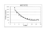
도 3은 본 발명에 따른 용수 재이용시스템에 의해 희석된 용수의 전기전도도를 도시한 도면이며,Figure 3 is a view showing the electrical conductivity of the water diluted by the water reuse system according to the present invention,
도 4는 본 발명의 제2실시예에 따른 용수 재이용시스템의 구성을 도시한 블록도이며,Figure 4 is a block diagram showing the configuration of a water reuse system according to a second embodiment of the present invention,
도 5는 본 발명에 따른 용수 재이용 방법을 도시한 흐름도이다.5 is a flowchart illustrating a water reuse method according to the present invention.
*도면의 주요 부분에 대한 부호의 설명** Description of the symbols for the main parts of the drawings *
10 : 유입장치 20 : 필터링장치10: inlet device 20: filtering device
20a : 여과장치 20b : 소독장치20a:
30 : 희석장치 30a : 감지부30:
30b : 제어부 30c : 디스플레이부30b:
30d : 저장부 40 : 공급장치30d: storage 40: supply device
50 : 유량조절장치 60 : 수질제어장치50: flow rate control device 60: water quality control device
본 발명은 용수 재이용시스템 및 용수 재이용방법에 관한 것이다. 보다 상세하게는, 하수처리수를 희석하는 용수 재이용시스템 및 용수 재이용방법에 관한 것이다.The present invention relates to a water reuse system and a water reuse method. More specifically, the present invention relates to a water reuse system and a water reuse method for diluting sewage treatment water.
우리나라는 농업용수와, 생활용수와, 공업용수의 용수수요량이 계속 증가하는 추세에 있으며, 용수의 공급량이 수요량에 미치지 못해 용수의 부족을 겪고 있다. 그 중에서도 농업용수는 국민의 식생활에 밀접한 관련이 있기 때문에 수질기준을 만족하는 농업용수를 적절히 공급하는 것은 중요한 문제이다. 특히, 2001년 수자원 장기계획에 의하면 2012년에는 수요관리 등을 통해 물 사용량을 억제한다고 하더라도 연간 약 18억 m3의 수자원이 부족할 것으로 예상하고 있다.In Korea, the demand for water for agriculture, living water, and industrial water continues to increase. Above all, since agricultural water is closely related to the diet of the people, it is important to supply agricultural water that satisfies the water quality standards. In particular, according to the 2001 Water Resources long-term plans in 2012, even if that inhibit water use through demand management, etc. it is expected to run out of water for 1.8 billion m3 per year.
용수의 부족을 해결하기 위한 방법으로는 용수의 수요관리 뿐만 아니라 대체수자원 개발과, 연계운영, 친환경적 신규 개발 등이 있지만, 그 중에서도 저렴한 비용에 의해 농업용수를 제공할 수 있는 장점이 있는 하수처리수의 재이용방법이 많이 이용된다.Solutions for water shortage include not only demand management but also alternative water resource development, linkage operation, and eco-friendly new development, but among them, sewage treatment water with the advantage of providing agricultural water at low cost. The reuse method of is widely used.
여기서, 종래의 용수 재이용시스템은 하수처리장으로부터 공급된 하수를 여 과장치에 의해 여과하고, 여과된 하수를 소독함으로써 하수처리수를 농업용수로 재이용한다. 그런데, 하수의 여과 및 소독에 의하더라도 처리된 하수의 전기전도도가 높아 농업용수로 이용함에 있어서 식물의 생장에 장애를 주며, 수중의 잔류오염물질 및 병원성 미생물이 잔존하는 문제가 있다.Here, the conventional water recycling system reuses the sewage treatment water as agricultural water by filtering the sewage supplied from the sewage treatment plant by a filtration device and disinfecting the filtered sewage. However, even by filtration and disinfection of sewage, the electrical conductivity of the treated sewage is high, which impedes the growth of plants when used as agricultural water, and there is a problem that residual pollutants and pathogenic microorganisms remain in the water.
따라서, 본 발명의 목적은 하수처리수에 대해 여과 및 소독 등을 수행할 뿐만 아니라 전기전도도를 낮추는 희석작용을 통하여, 저렴한 비용으로 안정적인 농업용수를 확보할 수 있는 용수 재이용시스템 및 용수 재이용방법을 제공하는 것이다.Accordingly, an object of the present invention is to provide a water reuse system and a water reuse method capable of securing stable agricultural water at low cost through a dilution action that not only performs filtration and disinfection of sewage treatment water but also lowers electrical conductivity. It is.
또한, 본 발명의 또다른 목적은 희석된 용수의 수질을 자동적으로 모니터링하고 목표값에 도달하도록 제어함으로써, 사용자의 편의성을 향상시키는 용수 재이용시스템 및 용수 재이용방법을 제공하는 것이다.It is still another object of the present invention to provide a water reuse system and a water reuse method for improving user convenience by automatically monitoring the water quality of diluted water and controlling to reach a target value.
상기 목적은, 용수 재이용시스템에 있어서, 상기 용수가 유입되는 유입장치와; 상기 유입된 용수를 필터링하는 필터링장치와; 상기 필터링된 용수의 전기전도도가 기설정된 값 이상인 경우, 상기 필터링된 용수를 희석하는 희석장치를 포함하는 것을 특징으로 하는 용수 재이용시스템에 의해 달성된다.The object of the present invention is to provide a water reuse system comprising: an inflow apparatus into which the water is introduced; A filtering device for filtering the introduced water; When the electrical conductivity of the filtered water is more than a predetermined value, it is achieved by a water reuse system comprising a dilution device for diluting the filtered water.
여기서, 상기 희석장치는 에너지 흐름법칙에 의해 상기 용수를 희석하는 것이 바람직하다.Here, it is preferable that the dilution device dilute the water by the law of energy flow.
그리고, 상기 필터링장치는, 상기 유입된 용수를 여과하는 여과장치와, 상기 유입된 용수를 소독하는 소독장치 중 적어도 어느 하나를 포함하는 것이 바람직하다.The filtering device preferably includes at least one of a filtration device for filtering the introduced water and a disinfection device for disinfecting the introduced water.
여기서, 상기 필터링장치와, 상기 희석장치 중 적어도 어느 하나는 상기 용수의 유량 및 지체속도를 제어하여 대장균 목표 수질을 제어하는 대장균 수질제어장치를 포함하는 것이 바람직하다.Here, at least one of the filtering device and the dilution device preferably includes an E. coli water quality control device for controlling the target water quality of E. coli by controlling the flow rate and the retardation speed of the water.
또한, 상기 희석된 용수를 펌프가압방식에 의해 외부로 공급하는 공급장치를 더 포함할 수 있다.The apparatus may further include a supply device for supplying the diluted water to the outside by a pump pressurization method.
그리고, 상기 외부로 공급되는 유량을 조절하는 유량조절장치를 더 포함할 수 있다.And, it may further include a flow rate adjusting device for adjusting the flow rate supplied to the outside.
여기서, 상기 외부로 공급되는 용수의 수질을 제어하는 수질제어장치를 더 포함하는 것이 바람직하다.Here, it is preferable to further include a water quality control device for controlling the water quality of the water supplied to the outside.
그리고, 상기 유입되는 용수는 하수처리장 방류수 및 지역오수 중 어느 하나를 포함하고, 상기 외부로 공급되는 용수는 농업용수를 포함하는 것이 바람직하다.The inflowing water may include any one of sewage treatment plant discharged water and local sewage, and the water supplied to the outside may include agricultural water.
한편, 용수 재이용방법에 있어서, 상기 용수가 유입되는 단계와; 상기 유입된 용수를 필터링하는 단계와; 상기 필터링된 용수의 전기전도도를 측정하는 단계와; 상기 측정된 전기전도도가 기설정된 값 이상인 경우, 상기 필터링된 용수를 희석하는 단계를 포함하는 것을 특징으로 하는 용수 재이용방법에 의해서도 상기 목적은 달성된다.On the other hand, water reuse method, the step of introducing the water; Filtering the introduced water; Measuring an electrical conductivity of the filtered water; The object is also achieved by the water reuse method, which comprises diluting the filtered water when the measured electrical conductivity is equal to or greater than a predetermined value.
여기서, 상기 용수를 희석하는 단계는, 에너지 흐름법칙에 의해 상기 용수를 희석하는 것이 바람직하다.Here, in the diluting of the water, it is preferable to dilute the water by the energy flow law.
또한, 상기 필터링하는 단계와, 상기 희석하는 단계 중 적어도 어느 하나는, 상기 용수의 유량 및 지체속도를 제어하여 대장균 목표 수질을 제어하는 단계를 더 포함할 수 있다.In addition, at least one of the filtering and diluting may further include controlling the target E. coli target water quality by controlling the flow rate and the retardation speed of the water.
그리고, 상기 희석된 용수를 펌프가압방식에 의해 외부로 공급하는 단계를 더 포함하는 것이 바람직하다.And, it is preferable to further include the step of supplying the diluted water to the outside by the pump pressure method.
또한, 상기 외부로 공급되는 용수의 유량을 조절하는 단계를 더 포함할 수 있다.In addition, the method may further include adjusting a flow rate of the water supplied to the outside.
그리고, 상기 외부로 공급되는 용수의 수질을 제어하는 단계를 더 포함할 수 있다.The method may further include controlling the water quality of the water supplied to the outside.
여기서, 상기 유입되는 용수는 하수처리장 방류수 및 지역오수 중 어느 하나를 포함하고, 상기 외부로 공급되는 용수는 농업용수를 포함하는 것이 바람직하다.Here, the inflowing water may include any one of sewage treatment plant discharged water and local sewage, and the water supplied to the outside may include agricultural water.
이하, 첨부된 도면을 참조하여 본 발명에 따른 용수 재이용시스템에 대해 상세히 설명한다.Hereinafter, with reference to the accompanying drawings will be described in detail for the water reuse system according to the present invention.
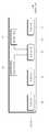
도 1은 본 발명의 제1실시예에 따른 용수 재이용시스템의 구성을 도시한 블록도이다. 도 1에 도시된 바와 같이, 본 발명의 제1실시예에 따른 용수 재이용시스템은 유입장치(10)와, 필터링장치(20)와, 희석장치(30)를 포함한다.1 is a block diagram showing the configuration of a water reuse system according to a first embodiment of the present invention. As shown in FIG. 1, the water reuse system according to the first embodiment of the present invention includes an
유입장치(10)는 용수가 유입되며, 유입장치(10)에 유입되는 용수는 하수처리장 방류수 및 지역오수 중 어느 하나를 포함할 수 있으며, 지역오수는 마을단위로 유입되는 것이 바람직하다. 용수가 하수처리수인 경우 하수처리장의 방류수구에서 펌프로 구현되며, 후술할 희석장치(30)에 필요한 희석수가 유입되는 유입장치가 별 도로 구비되는 것도 가능하다.
필터링장치(20)는 유입장치(10)로부터 유입된 용수를 필터링한다. 도 2a는 본 발명에 따른 필터링장치(20)를 도시한 도면이다. 도 2a에 도시된 바와 같이, 본 발명에 따른 필터링장치(20)는 여과장치(20a)와, 소독장치(20b)를 포함한다. 물론, 필터링장치(20)는 여과장치(20a)와, 소독장치(20b) 중 어느 하나만을 포함하는 것도 가능하다.The
여과장치(20a)는 유입장치(10)에 의해 유입된 용수를 여과하며, 보다 바람직하게는 완속모래를 이용하여 용수를 여과한다. 완속모래를 이용하는 경우, 용수의 탁도를 낮게 하여 살균효과를 증대시킬 수 있다. 그리고, 여과장치(20a)는 완속모래 이외에도 효율이 뛰어난 여재, 예를 들어 스폰지, 섬유 필터, 마이크로칩 필터, 바이오 필터 등을 이용하여 용수를 여과할 수 있다.The
소독장치(20b)는 유입장치(10)에 의해 유입된 용수를 소독하며, 보다 바람직하게는 자외선(Ultraviolet)에 의해 용수를 소독한다. 자외선에 의해 용수를 소독하는 경우, 소독제가 잔류하지 않고 과잉주입의 우려가 없으며 단순한 구조로 소독장치를 구성할 수 있는 장점이 있다.The
물론, 본 발명에 따른 소독장치(20b)는 염소, 오존(Ozone), 이산화염소(Chlorine dioxide), 클로라민(Choloramine) 등의 다양한 매체를 이용하여 용수를 소독할 수 있다.Of course, the
그리고, 본 발명에 따른 용수 재이용시스템(100)은 여과 및 소독 뿐만 아니라, 여과 및 소독된 용수를 재처리하여 저장 및 공급할 수 있는 저류공정을 더 거 칠 수 있다. 본 발명에 따른 용수 재이용시스템(100)에 하수처리수가 유입되어 농업용수를 공급하는 경우 5월부터 10월까지의 관개기간 중에 농업용수를 단속적으로 공급할 수 있으며, 관개기간 중에도 영농방법 또는 강우에 따라 농업용수를 공급하는 것이 가능하다.In addition, the
희석장치(30)는 필터링부(20)에 의해 필터링된 용수의 전기전도도가 기설정된 값 이상인 경우, 필터링된 용수를 희석한다. 구체적으로, 본 발명에 따른 희석장치(30)는 필터링된 용수를 희석수조 내에서 희석수와 혼합한다. 이러한 혼합과정은 필터링된 용수의 수질에 따라 반복될 수 있으며, 필터링된 용수의 전기전도도가 기설정값 이하가 될 때까지 반복되는 것이 바람직하다. 그리고, 필터링된 용수를 희석하기 위한 희석수는 일반적으로 지하수와, 하천수와, 저수지 담수 등을 포함하며, 균일한 수질의 매체인 증류수를 포함할 수 있으며, 희석장치(30) 내에 마련된 저장장치(미도시)에 저장될 수 있다.The
여기서, 본 발명에 따른 희석장치(30)에서는 에너지 흐름법칙에 의해 용수와 희석수가 혼합됨으로써 용수가 희석된다. 즉, 별도의 외부 에너지 없이도 용수와 희석수의 희석이 가능하다. 그리하여, 필터링된 용수는 희석수와 혼합되면 에너지 흐름법칙에 의해 전기전도도가 빠른 속도로 낮아지게 된다. 다만, 에너지 플럭스의 성장을 위해서 입자 간의 충돌이 필수적이므로 희석장치(30)에서 용수의 흐름속도를 느리게 하거나, 용수를 진동시켜 입자 간의 충돌을 유도할 수 있다. 또한, 본 발명에 따른 희석장치(30)는 용수와 희석수의 교반을 위한 교반기(미도시)를 포함하는 것도 가능하다.Here, in the
한편, 본 발명에 따른 희석장치(30)는 도 2b에 도시된 바와 같이, 감지부(30a)와, 제어부(30b)와, 저장부(30c)와, 디스플레이부(30d)를 포함할 수 있다.Meanwhile, as shown in FIG. 2B, the
감지부(30a)는 센서로 구현되어 필터링된 용수의 수질을 감지한다. 보다 바람직하게는 필터링된 용수의 전기전도도를 감지하여 제어부(30b)로 전달한다.The
제어부(30b)는 감지부(30a)에 의해 감지된 용수의 전기전도도가 기설정값 이상인지 여부를 판단한다. 그리하여, 판단 결과 필터링된 용수의 전기전도도가 기설정값 이상인 경우, 용수의 전기전도도가 기설정값 이하기 되도록 희석수의 혼합과정을 반복한다. 본 발명에 따른 제어부(30b)는 마이컴 및 소프트웨어로 구현될 수 있다.The
그리고, 본 발명에 따른 희석장치(30)는 용수의 전기전도도를 포함한 다양한 정보를 표시하는 디스플레이부(30c)를 더 포함할 수 있다. 그리하여, 사용자에게 희석된 용수의 수질에 대한 정보를 알릴 수 있다.In addition, the
본 발명에 따른 희석장치(30)는 저장부(30d)를 구비하여 감지된 전기전도도를 포함한 정보를 저장할 수 있다. 저장부(30d)는 용수의 전기전도도와 희석수의 희석배수를 포함한 정보를 데이터베이스에 의해 저장하는 것이 바람직하다.The
한편, 본 발명에 따른 필터링장치(20)와, 희석장치(30) 중 적어도 어느 하나는 용수의 유량 및 지체속도를 제어하여 대장균 목표 수질을 측정하고 제어하는 대장균 수질제어장치(미도시)를 포함할 수 있다. 이로써, 용수를 필터링하고 희석함과 동시에 대장균 목표 수질을 만족하는 농업용수를 외부에 공급할 수 있다. 여기서, 대장균 수질제어장치는 후술할 수질제어장치(60)에 포함되는 것도 가능하다.Meanwhile, at least one of the
또한, 본 발명에 따른 용수 재이용시스템(100)은 사용자가 원하는 전기전도도를 입력받기 위한 사용자입력부(미도시)를 포함할 수 있다.In addition, the
여기서, 감지부(30a)와, 제어부(30b)와, 디스플레이부(30c)와, 저장부(30d)가 희석장치(30) 내에 구비되는 것을 일예로 설명하고 있지만, 이들은 희석장치(30) 외부에 존재하는 것도 가능하다.Here, the
이하, 표 1과 도 3을 참조하여 본 발명에 따른 용수 재이용시스템(100)에 의해 희석된 용수의 전기전도도의 변화에 대해 설명한다.Hereinafter, with reference to Table 1 and FIG. 3, the change in the electrical conductivity of the water diluted by the
표 1은 전주시 하수종말처리장의 방류수를 본 발명에 따른 용수 재이용시스템(100)에 의해 희석한 결과, 희석된 용수의 전기전도도를 나타낸 표이다.Table 1 is a table showing the electrical conductivity of the diluted water as a result of diluting the discharged water of the sewage terminal treatment plant in Jeonju by the
표 1에 기재된 바와 같이, 하수종말처리장의 방류수를 순차적으로 희석한 결과, 희석된 용수의 전기전도도는 증류수의 양이 증가함에 따라 낮아지며, 실측값과 이론값은 대체로 일치하였다.As shown in Table 1, when the effluent water of the sewage treatment plant was sequentially diluted, the electrical conductivity of the diluted water decreased as the amount of distilled water increased, and the measured value and the theoretical value were generally in agreement.
여기서, 전기전도도의 실측값과 이론값이 일치하지 않는 이유는 희석수의 내부에서 용매와 용질 간에 상호 인력이 작용하고, 희석장치(30)에 함유되어 있는 성분의 증기압의 영향에 의한 것이다. 따라서, 실측값에 의하면 전기전도도의 감소량이 용액성분의 몰분율에 100% 비례하지는 않는다. 그러나, 용액의 전기전도도가 큰 경우, 용매와 용질 간의 상호작용이 증가하게 되고 증기압력의 감소효과가 발생하므로 실측값과 이론값의 편차가 크게 나타나며, 용액의 전기전도도가 작은 경우, 용매와 용질 간의 상호작용이 무시할 수 있을 정도로 작기 때문에 편차가 더욱 작아진다.The reason why the measured value and the theoretical value of the electrical conductivity do not coincide with each other is due to the mutual attraction between the solvent and the solute inside the dilution water and the influence of the vapor pressure of the components contained in the
한편, 도 3에 도시된 바와 같이, 희석장치(30)에 의해 희석된 용수의전기전도도는 50us/cm에 대응하는 것이 바람직하다. 물론, 필요한 농업용수의 수질에 따라 목표 전기전도도 값은 조절될 수 있다.On the other hand, as shown in Figure 3, the electrical conductivity of the water diluted by the
이하, 도 4를 참조하여 본 발명의 제2실시예에 따른 용수 재이용시스템(200)에 대해 상세히 설명한다.Hereinafter, the water reuse system 200 according to the second embodiment of the present invention will be described in detail with reference to FIG. 4.
도 4에 도시된 바와 같이, 본 발명의 제2실시예에 따른 용수 재이용시스템(200)은 공급장치(40)와, 유량조절장치(50)와, 수질제어장치(60)를 더 포함한다. 본 발명의 제1실시예에 따른 용수 재이용시스템(100)과 중복되는 구성에 대해서는 설명을 생략한다.As shown in FIG. 4, the water reuse system 200 according to the second embodiment of the present invention further includes a
공급장치(40)는 희석장치(30)에 의해 희석된 용수를 외부로 공급하며, 보다 바람직하게는 펌프가압방식에 의해 용수를 외부로 공급한다. 공급장치(40)는 용수의 원활한 유동을 위해 가압력을 부여하여 용수를 외부로 공급하며, 별도의 감지부(미도시)를 구비하여 외부로 공급되는 용수의 오염도를 측정할 수도 있다. 물론, 본 발명에 따른 공급장치(40)는 수문개폐방식에 의하는 것도 가능하다.The
유량조절장치(50)는 용수의 유량을 조절하며, 유량이 조절되는 용수는 유입장치(10)에 의해 유입되는 용수와, 희석장치(30)에 의해 희석되는 용수와, 공급장치(40)에 의해 외부로 공급되는 용수 중 적어도 어느 하나를 포함한다.The
구체적으로, 본 발명에 따른 유량조절장치(50)는 유량조절밸브에 의해 용수의 유량을 조절할 수 있으며, 유량조절장치(50)는 유입장치(10)와, 필터링장치(20)와, 희석장치(30)와, 공급장치(40) 각각에 구비되는 것도 가능하다.Specifically, the
수질제어장치(60)는 용수의 수질을 제어하며, 희석장치(30)에 의해 희석되어 공급장치(40)에 의해 외부로 공급되는 용수의 수질을 제어하는 것이 바람직하다.The water
본 발명에 따른 수질제어장치(60)는 공급장치(40)에 의해 외부로 공급되는 용수의 전기전도도가 기설정된 목표값의 허용범위에 속하지 않는 경우, 유입장치(10)에 의해 유입되는 용수와, 희석장치(30)가 용수를 희석하는 데 필요한 희석수의 유량을 조절하도록 유량조절장치(50)를 제어할 수 있다. 그리고, 수질제어장치(60)는 희석장치(30)와 마찬가지로 저장부(미도시)를 구비하여 외부로 공급되는 용수의 전기전도도를 저장할 수 있다.The water
이하, 도 5를 참조하여 본 발명에 따른 용수 재이용방법에 대해 설명한다.Hereinafter, a water reuse method according to the present invention will be described with reference to FIG. 5.
먼저, 용수가 유입장치(10)에 의해 유입되면(S10), 유입된 용수를 필터링부(20)에 의해 필터링한다(S20). 여기서, 단계 S10에서 유입되는 용수는 하수처리장 방류수 및 지역오수 중 어느 하나를 포함할 수 있으며, 지역오수는 마을단위로 유입되는 것이 바람직하다.First, when water is introduced by the inflow device 10 (S10), the water is filtered by the filtering unit 20 (S20). Here, the water flowing in step S10 may include any one of sewage treatment plant effluent and local sewage, the local sewage is preferably introduced into the village unit.
그리고, 단계 S20에서 필터링부(20)에 의해 필터링된 용수의 전기전도도를 측정한다(S30). 단계 S30에서 측정된 전기전도도가 기설정된 값 이상인지 여부를 판단하여(S40), 전기전도도가 기설정된 값 이상인 경우 필터링부(20)에 의해 필터링된 용수를 희석장치(30)에 의해 희석한다(S50).Then, the electrical conductivity of the water filtered by the
여기서, 단계 S50은 에너지 흐름법칙에 의해 용수를 희석하는 것이 바람직하며, 희석된 용수를 공급장치(40)에 의해 외부로 공급하는 단계를 더 포함할 수 있다. 그리고, 단계 S50은 희석된 용수의 유량을 조절하는 단계와, 희석된 용수의 수질을 제어하는 단계를 포함할 수 있다.Here, step S50 preferably dilutes the water by the energy flow law, and may further include supplying the diluted water to the outside by the
이상, 바람직한 실시예를 통하여 본 발명에 관하여 상세히 설명하였으나, 본 발명은 이에 한정되는 것은 아니며 특허청구범위 내에서 다양하게 실시될 수 있다.As mentioned above, the present invention has been described in detail through preferred embodiments, but the present invention is not limited thereto and may be variously implemented within the scope of the claims.
상기한 바와 같이, 본 발명에 따른 용수 재이용시스템 및 용수 재이용방법에 의하면 하수처리수를 여과 및 소독하고 전기전도도를 낮춤으로써, 저렴한 비용으로 안정적인 농업용수를 확보할 수 있다.As described above, according to the water reuse system and the water reuse method according to the present invention, by filtering and disinfecting the sewage treatment water and lowering the electrical conductivity, it is possible to secure stable agricultural water at low cost.
또한, 본 발명에 따른 용수 재이용시스템 및 용수 재이용방법에 의하면 희석된 용수의 수질을 자동적으로 모니터링하고 목표값에 도달하도록 제어함으로써, 사용자의 편의성을 제공할 수 있다.In addition, according to the water reuse system and the water reuse method according to the present invention can provide a user convenience by automatically monitoring the water quality of the diluted water and controlling to reach the target value.
Claims (15)
Translated fromKoreanPriority Applications (1)
| Application Number | Priority Date | Filing Date | Title |
|---|---|---|---|
| KR1020070046181AKR100812308B1 (en) | 2007-05-11 | 2007-05-11 | Water Reuse System and Water Reuse Method |
Applications Claiming Priority (1)
| Application Number | Priority Date | Filing Date | Title |
|---|---|---|---|
| KR1020070046181AKR100812308B1 (en) | 2007-05-11 | 2007-05-11 | Water Reuse System and Water Reuse Method |
Publications (1)
| Publication Number | Publication Date |
|---|---|
| KR100812308B1true KR100812308B1 (en) | 2008-03-10 |
Family
ID=39398379
Family Applications (1)
| Application Number | Title | Priority Date | Filing Date |
|---|---|---|---|
| KR1020070046181AActiveKR100812308B1 (en) | 2007-05-11 | 2007-05-11 | Water Reuse System and Water Reuse Method |
Country Status (1)
| Country | Link |
|---|---|
| KR (1) | KR100812308B1 (en) |
Cited By (2)
| Publication number | Priority date | Publication date | Assignee | Title |
|---|---|---|---|---|
| KR100839026B1 (en) | 2007-11-30 | 2008-06-17 | 한국농촌공사 | Desalination system for brackish water and how to convert brackish water to agricultural reuse water |
| WO2025133452A1 (en)* | 2023-12-22 | 2025-06-26 | Kemira Oyj | Wastewater effluent reuse |
Citations (4)
| Publication number | Priority date | Publication date | Assignee | Title |
|---|---|---|---|---|
| KR20010099528A (en)* | 2000-04-27 | 2001-11-09 | 이인화 | Nutrient solution disinfection and recycling system by utilizing ultraviolet light and photocatalyst effect |
| KR20020050437A (en)* | 2000-12-21 | 2002-06-27 | 신현준 | method for reusing rainwater |
| JP2004298055A (en) | 2003-03-31 | 2004-10-28 | Shimane Pref Gov | Culture solution production and supply system |
| KR20040101802A (en)* | 2003-05-27 | 2004-12-03 | 한라콘크리트 주식회사 | The equipment to stabilize and recycle withdrawed water |
- 2007
- 2007-05-11KRKR1020070046181Apatent/KR100812308B1/enactiveActive
Patent Citations (4)
| Publication number | Priority date | Publication date | Assignee | Title |
|---|---|---|---|---|
| KR20010099528A (en)* | 2000-04-27 | 2001-11-09 | 이인화 | Nutrient solution disinfection and recycling system by utilizing ultraviolet light and photocatalyst effect |
| KR20020050437A (en)* | 2000-12-21 | 2002-06-27 | 신현준 | method for reusing rainwater |
| JP2004298055A (en) | 2003-03-31 | 2004-10-28 | Shimane Pref Gov | Culture solution production and supply system |
| KR20040101802A (en)* | 2003-05-27 | 2004-12-03 | 한라콘크리트 주식회사 | The equipment to stabilize and recycle withdrawed water |
Cited By (2)
| Publication number | Priority date | Publication date | Assignee | Title |
|---|---|---|---|---|
| KR100839026B1 (en) | 2007-11-30 | 2008-06-17 | 한국농촌공사 | Desalination system for brackish water and how to convert brackish water to agricultural reuse water |
| WO2025133452A1 (en)* | 2023-12-22 | 2025-06-26 | Kemira Oyj | Wastewater effluent reuse |
Similar Documents
| Publication | Publication Date | Title |
|---|---|---|
| EP1017628B1 (en) | Water treatment system having dosing control | |
| KR101712582B1 (en) | recycle supplying systems of nutrient solution of cultivation under structure used ICT | |
| EP2527303A1 (en) | Reverse osmosis assembly | |
| EP1131481A1 (en) | Ozonated laundry system with water re-use capability | |
| KR101050374B1 (en) | Automatic operation device of small sewage treatment facility | |
| EP1089943A1 (en) | Filter cartridge assembly | |
| KR101259698B1 (en) | Water Treatment System of Water Park | |
| EP2706042A1 (en) | Point-of-use water dispenser and method for using said water dispenser | |
| US10689276B2 (en) | System and method for water disinfection | |
| KR100812308B1 (en) | Water Reuse System and Water Reuse Method | |
| JP2003126855A (en) | Membrane filtration system | |
| KR20130104089A (en) | Water treatment apparatus and water treatment method | |
| KR101274983B1 (en) | Method and apparatus for determining of the remained chlorine concentration using a sensor, and purified-water treatment system using the same | |
| KR101772558B1 (en) | Management System and Method for A Swimming Pool | |
| JP2004049953A (en) | UV disinfection device and disinfection system using the same | |
| CN104843914B (en) | Large-capacity integrated pure water supply system for laboratory | |
| KR101765669B1 (en) | Sterilizing Apparatus and Method of Inner Flow Path in Water Purifier | |
| KR101775845B1 (en) | Sterilizing method of waste nutrient solution using uv lamp | |
| KR102121841B1 (en) | Multi-source water treatment optimization system | |
| KR101774454B1 (en) | water quality purification equipment for swimming pool, and water quality purification methods | |
| KR101719349B1 (en) | Sterilization and cleaning kit using citric acid | |
| JP2004009032A (en) | Method of manufacturing deionized water, and hydroponics method and apparatus | |
| KR101729690B1 (en) | Clorine generator and management system using the same | |
| CN210237300U (en) | Oxidation-reduction potential accurate control system for reverse osmosis device | |
| CN114600760A (en) | Nutrient solution return irrigation adjusting method and nutrient solution circulating system |
Legal Events
| Date | Code | Title | Description |
|---|---|---|---|
| A201 | Request for examination | ||
| PA0109 | Patent application | Patent event code:PA01091R01D Comment text:Patent Application Patent event date:20070511 | |
| PA0201 | Request for examination | ||
| A302 | Request for accelerated examination | ||
| PA0302 | Request for accelerated examination | Patent event date:20070828 Patent event code:PA03022R01D Comment text:Request for Accelerated Examination Patent event date:20070511 Patent event code:PA03021R01I Comment text:Patent Application | |
| E902 | Notification of reason for refusal | ||
| PE0902 | Notice of grounds for rejection | Comment text:Notification of reason for refusal Patent event date:20071022 Patent event code:PE09021S01D | |
| E701 | Decision to grant or registration of patent right | ||
| PE0701 | Decision of registration | Patent event code:PE07011S01D Comment text:Decision to Grant Registration Patent event date:20080130 | |
| GRNT | Written decision to grant | ||
| PR0701 | Registration of establishment | Comment text:Registration of Establishment Patent event date:20080304 Patent event code:PR07011E01D | |
| PR1002 | Payment of registration fee | Payment date:20080305 End annual number:3 Start annual number:1 | |
| PG1601 | Publication of registration | ||
| G170 | Re-publication after modification of scope of protection [patent] | ||
| PG1701 | Publication of correction | ||
| PR1001 | Payment of annual fee | Payment date:20110303 Start annual number:4 End annual number:4 | |
| PR1001 | Payment of annual fee | Payment date:20120605 Start annual number:5 End annual number:5 | |
| FPAY | Annual fee payment | Payment date:20130404 Year of fee payment:6 | |
| PR1001 | Payment of annual fee | Payment date:20130404 Start annual number:6 End annual number:6 | |
| FPAY | Annual fee payment | Payment date:20140228 Year of fee payment:7 | |
| PR1001 | Payment of annual fee | Payment date:20140228 Start annual number:7 End annual number:7 | |
| FPAY | Annual fee payment | Payment date:20150212 Year of fee payment:8 | |
| PR1001 | Payment of annual fee | Payment date:20150212 Start annual number:8 End annual number:8 | |
| FPAY | Annual fee payment | Payment date:20160122 Year of fee payment:9 | |
| PR1001 | Payment of annual fee | Payment date:20160122 Start annual number:9 End annual number:9 | |
| FPAY | Annual fee payment | Payment date:20180222 Year of fee payment:11 | |
| PR1001 | Payment of annual fee | Payment date:20180222 Start annual number:11 End annual number:11 | |
| FPAY | Annual fee payment | Payment date:20200302 Year of fee payment:13 | |
| PR1001 | Payment of annual fee | Payment date:20200302 Start annual number:13 End annual number:13 | |
| PR1001 | Payment of annual fee | Payment date:20210324 Start annual number:14 End annual number:14 | |
| PR1001 | Payment of annual fee | Payment date:20220705 Start annual number:15 End annual number:15 |