KR100808845B1 - Method for refrigeration system control - Google Patents
Method for refrigeration system controlDownload PDFInfo
- Publication number
- KR100808845B1 KR100808845B1KR1020070064953AKR20070064953AKR100808845B1KR 100808845 B1KR100808845 B1KR 100808845B1KR 1020070064953 AKR1020070064953 AKR 1020070064953AKR 20070064953 AKR20070064953 AKR 20070064953AKR 100808845 B1KR100808845 B1KR 100808845B1
- Authority
- KR
- South Korea
- Prior art keywords
- temperature
- refrigeration
- case
- data
- controller
- Prior art date
- Legal status (The legal status is an assumption and is not a legal conclusion. Google has not performed a legal analysis and makes no representation as to the accuracy of the status listed.)
- Expired - Fee Related
Links
Images


Classifications
- F—MECHANICAL ENGINEERING; LIGHTING; HEATING; WEAPONS; BLASTING
- F25—REFRIGERATION OR COOLING; COMBINED HEATING AND REFRIGERATION SYSTEMS; HEAT PUMP SYSTEMS; MANUFACTURE OR STORAGE OF ICE; LIQUEFACTION SOLIDIFICATION OF GASES
- F25D—REFRIGERATORS; COLD ROOMS; ICE-BOXES; COOLING OR FREEZING APPARATUS NOT OTHERWISE PROVIDED FOR
- F25D29/00—Arrangement or mounting of control or safety devices
- H—ELECTRICITY
- H04—ELECTRIC COMMUNICATION TECHNIQUE
- H04Q—SELECTING
- H04Q9/00—Arrangements in telecontrol or telemetry systems for selectively calling a substation from a main station, in which substation desired apparatus is selected for applying a control signal thereto or for obtaining measured values therefrom
- G—PHYSICS
- G05—CONTROLLING; REGULATING
- G05D—SYSTEMS FOR CONTROLLING OR REGULATING NON-ELECTRIC VARIABLES
- G05D23/00—Control of temperature
- G05D23/19—Control of temperature characterised by the use of electric means
- G—PHYSICS
- G05—CONTROLLING; REGULATING
- G05D—SYSTEMS FOR CONTROLLING OR REGULATING NON-ELECTRIC VARIABLES
- G05D23/00—Control of temperature
- G05D23/19—Control of temperature characterised by the use of electric means
- G05D23/1902—Control of temperature characterised by the use of electric means characterised by the use of a variable reference value
- G05D23/1905—Control of temperature characterised by the use of electric means characterised by the use of a variable reference value associated with tele control
- F—MECHANICAL ENGINEERING; LIGHTING; HEATING; WEAPONS; BLASTING
- F25—REFRIGERATION OR COOLING; COMBINED HEATING AND REFRIGERATION SYSTEMS; HEAT PUMP SYSTEMS; MANUFACTURE OR STORAGE OF ICE; LIQUEFACTION SOLIDIFICATION OF GASES
- F25B—REFRIGERATION MACHINES, PLANTS OR SYSTEMS; COMBINED HEATING AND REFRIGERATION SYSTEMS; HEAT PUMP SYSTEMS
- F25B2400/00—General features or devices for refrigeration machines, plants or systems, combined heating and refrigeration systems or heat-pump systems, i.e. not limited to a particular subgroup of F25B
- F25B2400/07—Details of compressors or related parts
- F25B2400/075—Details of compressors or related parts with parallel compressors
- F—MECHANICAL ENGINEERING; LIGHTING; HEATING; WEAPONS; BLASTING
- F25—REFRIGERATION OR COOLING; COMBINED HEATING AND REFRIGERATION SYSTEMS; HEAT PUMP SYSTEMS; MANUFACTURE OR STORAGE OF ICE; LIQUEFACTION SOLIDIFICATION OF GASES
- F25B—REFRIGERATION MACHINES, PLANTS OR SYSTEMS; COMBINED HEATING AND REFRIGERATION SYSTEMS; HEAT PUMP SYSTEMS
- F25B2400/00—General features or devices for refrigeration machines, plants or systems, combined heating and refrigeration systems or heat-pump systems, i.e. not limited to a particular subgroup of F25B
- F25B2400/22—Refrigeration systems for supermarkets
- F—MECHANICAL ENGINEERING; LIGHTING; HEATING; WEAPONS; BLASTING
- F25—REFRIGERATION OR COOLING; COMBINED HEATING AND REFRIGERATION SYSTEMS; HEAT PUMP SYSTEMS; MANUFACTURE OR STORAGE OF ICE; LIQUEFACTION SOLIDIFICATION OF GASES
- F25B—REFRIGERATION MACHINES, PLANTS OR SYSTEMS; COMBINED HEATING AND REFRIGERATION SYSTEMS; HEAT PUMP SYSTEMS
- F25B2600/00—Control issues
- F25B2600/07—Remote controls
- F—MECHANICAL ENGINEERING; LIGHTING; HEATING; WEAPONS; BLASTING
- F25—REFRIGERATION OR COOLING; COMBINED HEATING AND REFRIGERATION SYSTEMS; HEAT PUMP SYSTEMS; MANUFACTURE OR STORAGE OF ICE; LIQUEFACTION SOLIDIFICATION OF GASES
- F25D—REFRIGERATORS; COLD ROOMS; ICE-BOXES; COOLING OR FREEZING APPARATUS NOT OTHERWISE PROVIDED FOR
- F25D2500/00—Problems to be solved
- F25D2500/04—Calculation of parameters
- F—MECHANICAL ENGINEERING; LIGHTING; HEATING; WEAPONS; BLASTING
- F25—REFRIGERATION OR COOLING; COMBINED HEATING AND REFRIGERATION SYSTEMS; HEAT PUMP SYSTEMS; MANUFACTURE OR STORAGE OF ICE; LIQUEFACTION SOLIDIFICATION OF GASES
- F25D—REFRIGERATORS; COLD ROOMS; ICE-BOXES; COOLING OR FREEZING APPARATUS NOT OTHERWISE PROVIDED FOR
- F25D2700/00—Means for sensing or measuring; Sensors therefor
- F25D2700/10—Sensors measuring the temperature of the evaporator
- F—MECHANICAL ENGINEERING; LIGHTING; HEATING; WEAPONS; BLASTING
- F25—REFRIGERATION OR COOLING; COMBINED HEATING AND REFRIGERATION SYSTEMS; HEAT PUMP SYSTEMS; MANUFACTURE OR STORAGE OF ICE; LIQUEFACTION SOLIDIFICATION OF GASES
- F25D—REFRIGERATORS; COLD ROOMS; ICE-BOXES; COOLING OR FREEZING APPARATUS NOT OTHERWISE PROVIDED FOR
- F25D2700/00—Means for sensing or measuring; Sensors therefor
- F25D2700/12—Sensors measuring the inside temperature
- F25D2700/123—Sensors measuring the inside temperature more than one sensor measuring the inside temperature in a compartment
- F—MECHANICAL ENGINEERING; LIGHTING; HEATING; WEAPONS; BLASTING
- F25—REFRIGERATION OR COOLING; COMBINED HEATING AND REFRIGERATION SYSTEMS; HEAT PUMP SYSTEMS; MANUFACTURE OR STORAGE OF ICE; LIQUEFACTION SOLIDIFICATION OF GASES
- F25D—REFRIGERATORS; COLD ROOMS; ICE-BOXES; COOLING OR FREEZING APPARATUS NOT OTHERWISE PROVIDED FOR
- F25D2700/00—Means for sensing or measuring; Sensors therefor
- F25D2700/16—Sensors measuring the temperature of products
- G—PHYSICS
- G01—MEASURING; TESTING
- G01K—MEASURING TEMPERATURE; MEASURING QUANTITY OF HEAT; THERMALLY-SENSITIVE ELEMENTS NOT OTHERWISE PROVIDED FOR
- G01K7/00—Measuring temperature based on the use of electric or magnetic elements directly sensitive to heat ; Power supply therefor, e.g. using thermoelectric elements
- G01K7/42—Circuits effecting compensation of thermal inertia; Circuits for predicting the stationary value of a temperature
- G01K2007/422—Dummy objects used for estimating temperature of real objects
Landscapes
- Engineering & Computer Science (AREA)
- Physics & Mathematics (AREA)
- Chemical & Material Sciences (AREA)
- Combustion & Propulsion (AREA)
- Mechanical Engineering (AREA)
- Thermal Sciences (AREA)
- General Engineering & Computer Science (AREA)
- General Physics & Mathematics (AREA)
- Automation & Control Theory (AREA)
- Computer Networks & Wireless Communication (AREA)
- Devices That Are Associated With Refrigeration Equipment (AREA)
- Cold Air Circulating Systems And Constructional Details In Refrigerators (AREA)
Abstract
Translated fromKoreanDescription
Translated fromKorean도 1은 본 발명의 바람직한 실시예에 따른 냉장 시스템을 제어하기 위한 방법 및 장치를 채용하는 냉장 시스템의 블록도.1 is a block diagram of a refrigeration system employing a method and apparatus for controlling a refrigeration system according to a preferred embodiment of the present invention.
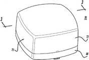
도 2는 본 발명에 따른 제품-시뮬레이팅 프로브의 사시도.2 is a perspective view of a product-simulating probe according to the present invention.
도 3은 도 2의 제품-시뮬레이팅 프로브의 저면 사시도.3 is a bottom perspective view of the product-simulating probe of FIG. 2.
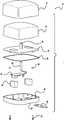
도 4는 도 2 및 도3의 제품-시뮬레이팅 프로브의 분해도.4 is an exploded view of the product-simulating probe of FIGS. 2 and 3.
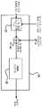
도 5는 본 발명에 따라 디스플레이 케이스로부터 주 제어기로 제품 온도 데이터를 전송하기 위한 하나의 구성을 예시하는 블록도.5 is a block diagram illustrating one configuration for transferring product temperature data from a display case to a main controller in accordance with the present invention.
도 6은 본 발명에 따라 디스플레이 케이스로부터 주 제어기로 제품 온도 데이터를 전송하기 위한 또다른 구성을 예시하는 블록도.6 is a block diagram illustrating another configuration for transferring product temperature data from a display case to a main controller in accordance with the present invention.
도 7은 본 발명에 따라 디스플레이 케이스로부터 주 제어기로 제품 온도 데이터 및 기타 모니터링된 데이터를 전송하기 위한 또다른 구성을 예시하는 블록도.7 is a block diagram illustrating another configuration for transmitting product temperature data and other monitored data from a display case to a main controller in accordance with the present invention.
도 8은 전자 압력 조절기를 사용한 회로 온도 제어를 예시하는 흐름도.8 is a flow chart illustrating circuit temperature control using an electronic pressure regulator.
도 9는 제품 시뮬레이터 온도 프로브에 기초한 플로팅 회로 또는 케이스 온도 제어를 예시하는 흐름도.9 is a flow diagram illustrating a floating circuit or case temperature control based on a product simulator temperature probe.
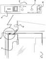
도 10은 본 발명에 따른 "세척"모드 스위치를 포함하고, 도 7의 블록도의 일부분을 나타내는 도.10 illustrates a portion of the block diagram of FIG. 7 including a “clean” mode switch in accordance with the present invention.
도 11은 본 발명에 따른 무선 주파수 모니터링 시스템을 예시하는 근사화도.11 is an approximation diagram illustrating a radio frequency monitoring system in accordance with the present invention.
도 12는 본 발명을 구현하는 냉장 시스템의 간명화된 다이아그램을 예시하는 근사화도.12 is an approximate diagram illustrating a simplified diagram of a refrigeration system embodying the present invention.
도 13은 본 발명에 따른 데드-밴드 제어를 사용하는 기화기 온도 제어를 예시하는 흐름도.13 is a flow diagram illustrating vaporizer temperature control using dead-band control in accordance with the present invention.
도 14는 본 발명에 따른 PI, PID 및 FL 제어를 사용하는 기화기 온도 제어를 예시하는 흐름도.14 is a flow diagram illustrating vaporizer temperature control using PI, PID and FL control in accordance with the present invention.
도 15는 냉장 시스템을 제어하는 데 사용하기 위한 에러 멤버쉽 함수 및 에러 비율 멤버쉽 함수를 각각 예시하는, 그래프 1 및 그래프 2를 포함하는 도.FIG. 15 includes Graph 1 and Graph 2, respectively illustrating an error membership function and an error rate membership function for use in controlling a refrigeration system.
본 발명은 일반적으로 식품 디스플레이 케이스의 온도를 모니터링 및 제어하는 것에 관한 것으로, 더욱 상세히는 식품 온도를 모니터링 및 제어하는 방법 및 장치에 관한 것이다.The present invention generally relates to monitoring and controlling the temperature of a food display case, and more particularly, to a method and apparatus for monitoring and controlling food temperature.
제조된 식품은 가공 공장으로부터 잡화점 가게로 운반되어, 오랫동안 디스플레이 케이스 선반에 놓이게 된다. 향상된 식품 품질을 위해, 제조 식품은 잡화점 가게 디스플레이 케이스에서 디스플레이되는 동안 임계 온도 한계치를 초과하지 않아야 한다. 조리되지 않은 제조 식품을 위해, 제품 온도는 41℉를 초과하지 않아야 하고, 조리된 제조 식품을 위해, 제품 온도는 140℉ 미만이 되지 않아야 한다. 다 른 말로 하면, 임계 온도 한계치는 약 41℉와 140℉ 사이 이어야 한다. 이러한 임계 온도 한계치 사이에서 박테리아는 고속으로 성장한다.The food produced is transported from the processing plant to the grocery store, where it is placed on display case shelves for a long time. For improved food quality, the manufactured food must not exceed the critical temperature limit while displayed in the grocery store display case. For uncooked manufactured foods, the product temperature should not exceed 41 ° F and for cooked prepared foods, the product temperature should not be below 140 ° F. In other words, the critical temperature limit should be between about 41 ° F and 140 ° F. Between these critical temperature limits, bacteria grow at a high rate.
제조 식품 온도를 안전한 한계치 이내에 유지시키려는 하나의 시도는 디스플레이 케이스가 지나치게 따뜻하거나 차갑게 되지 않도록 하기 위해 배출 공기 온도를 모니터링하는 것이다. 하지만, 제조 식품 온도와 배출 공기 온도는 반드시 상관관계에 있지 않다. 즉, 제조 식품 온도와 배출 공기 온도는 반드시 동일한 온도 경향을 띠지 않는 데 이는 제조 식품 온도는 제조 식품의 열 매스(mass)에 기인하여 배출 공기 온도가 크게 변동하기 때문이다. 더욱이, 초기 스타트업 및 디스플레이 케이스를 해동하는 동안, 공기 온도는 70℉에 이를 수 있는 반면에, 제조 식품 온도는 짧은 시간간격 동안에 훨씬 낮은 온도에 이를 수 있다. 결과적으로, 디스플레이 케이스내의 제조 식품의 온도를 모니터링하기 위해 일정 간격으로 제조 식품의 온도를 측정하는 것을 실제적이지 못하다.One attempt to keep the manufactured food temperature within safe limits is to monitor the exhaust air temperature to prevent the display case from becoming too warm or cold. However, the food temperature produced and the exhaust air temperature are not necessarily correlated. That is, the manufactured food temperature and the exhaust air temperature do not necessarily have the same temperature tendency, because the manufactured food temperature fluctuates greatly in the exhaust air temperature due to the thermal mass of the manufactured food. Moreover, while thawing the initial startup and display case, the air temperature can reach 70 ° F, while the manufactured food temperature can reach much lower temperatures for shorter time intervals. As a result, it is not practical to measure the temperature of the manufactured food at regular intervals to monitor the temperature of the manufactured food in the display case.
더욱 상세히는, 종래의 냉장 시스템에서, 주 제어기는 통상 온도를 기록(log) 및 제어한다. 일반적으로, 주 제어기는 잡화점 가게의 뒤편 또는 지붕에 위치된 압축기 실에 설치된다. 디스플레이 케이스 온도를 모니터링 및 제어하는 종래의 방법은 디스플레이 케이스에 설치된 배출 공기 온도 센서를 필요로 한다. 배출 공기 온도 센서는 전형적으로 압축기 실에 위치되는 아날로그 입력 보드에 연결된다. 온도 배선은 디스플레이 케이스로부터 압축기 실로 끌어내어 져야 하는 데, 이는 쉽지 않은 일이고 압축기 실이 디스플레이 케이스로부터 떨어져 있는 정도에 따라 비용이 많이 드는 일이다. 또한, 이러한 배선 및 설치 프로세스는 점포를 재 개장할 때 부담이 되고 비용이 많이들게 된다.More specifically, in conventional refrigeration systems, the main controller typically logs and controls the temperature. In general, the main controller is installed in a compressor chamber located behind or on the roof of a grocery store. Conventional methods of monitoring and controlling the display case temperature require an exhaust air temperature sensor installed in the display case. The exhaust air temperature sensor is typically connected to an analog input board located in the compressor compartment. Temperature wiring must be drawn from the display case to the compressor compartment, which is not easy and expensive, depending on how far the compressor compartment is from the display case. In addition, this wiring and installation process becomes burdensome and expensive when remodeling the store.
또한, 디스플레이 케이스는 주기적인 세척 및 유지보수를 필요로 하고, 이동안 디스플레이 케이스의 온도는 변동한다. 그러므로, 세척 및 유지보수 동안, 제어기가 디스플레이 케이스 온도를 모니터링 및 제어하는 것은 바람직하지 못하다.In addition, the display case requires periodic cleaning and maintenance, during which the temperature of the display case fluctuates. Therefore, during cleaning and maintenance, it is undesirable for the controller to monitor and control the display case temperature.
본 발명에 따른 냉장 시스템을 제어하는 방법 및 장치는 시뮬레이팅된 제품 데이터의 무선 전송을 제공함으로써 종래 기술의 한계를 극복한다. 본 발명에 따른 장치는 적어도 하나의 냉장 케이스 및 압축기 래크를 갖는 복수의 회로를 포함한다. 각각의 회로와 통신하는 전자 기화기 압력 조절기는 상기 회로중의 하나의 온도를 제어한다. 각각의 회로와 통신하는 센서는 회로로부터의 파라미터를 측정하고, 이 센서와 통신하는 트랜시버는 측정된 파라미터를 무선으로 전송한다. 수신기는 무선으로 전송된 측정된 파라미터를 수신한다. 수신기와 통신하는 제어기는 각각의 회로로부터 무선으로 전송된 측정된 파라미터에 기초하여 상기 압축기 래크의 흡입 압력 및 각각의 전자 기화기 압력 조절기를 제어한다.The method and apparatus for controlling a refrigeration system according to the present invention overcomes the limitations of the prior art by providing wireless transmission of simulated product data. The device according to the invention comprises a plurality of circuits having at least one refrigeration case and a compressor rack. An electronic vaporizer pressure regulator in communication with each circuit controls the temperature of one of the circuits. A sensor in communication with each circuit measures a parameter from the circuit, and a transceiver in communication with the sensor transmits the measured parameter wirelessly. The receiver receives the measured parameter transmitted wirelessly. A controller in communication with the receiver controls the suction pressure of each compressor rack and each electronic vaporizer pressure regulator based on measured parameters wirelessly transmitted from each circuit.
바람직하게, 본 발명의 트랜시버는 저전력을 소모한다. 저전력 트랜시버는 제한된 전송 범위를 가지고 이에따라 수신기에 근접하여 위치될 것을 필요로 한다. 저전력 트랜시버의 사용은 냉장고 케이스가 수신기로부터 위치되어야 할 거리를 제한할 수 있기 때문에, 본 발명은 수신기와 냉장고 케이스간에 신호를 수신 및 전송하는 일련의 중계기를 포함한다. 이 중계기는 수신기와 냉장고 케이스간의 거리를 넓힐 수 있는 브리지로서의 작용한다.Preferably, the transceiver of the present invention consumes low power. Low power transceivers have a limited transmission range and therefore need to be located in close proximity to the receiver. Since the use of low power transceivers can limit the distance that the refrigerator case should be located from the receiver, the present invention includes a series of repeaters for receiving and transmitting signals between the receiver and the refrigerator case. The repeater acts as a bridge that can extend the distance between the receiver and the refrigerator case.
본 발명은 또한, 바람직하게, 제1 또는 제2 모드에서 작동할 수 있는 모드 스위치를 포함한다. 이 모드 스위치는 제어기가 온도를 기록 및 조절하는 것을 일시 중지시키도록 신호하는 데 유용하다. 이 스위치는 냉장고 케이스를 세척 및 유지보수하는 동안에 유용하다.The invention also preferably comprises a mode switch capable of operating in the first or second mode. This mode switch is useful for signaling the controller to pause recording and adjusting temperature. This switch is useful during cleaning and maintenance of the refrigerator case.
도 1을 참조하면, 본 발명의 바람직한 실시예에 따른 냉장 시스템(10)의 상세한 블록도가 도시되어 있다. 냉장 시스템(10)은 압축기 래크(18) 내부에 모두 위치된 배출 헤더(16)와 공통 흡입 매니폴드(14)와 압축기 실(6)에서 함께 배관된 복수의 압축기(12)를 포함한다. 압축기 래크(18)는 냉각제 증기가 고압에서 액화되는 컨덴서(20)로 운반되는 냉각제 증기를 압축한다. 이 고압 액화된 냉각제는 배관(24)에 의해 잡화점 가게 플로어 공간(8)의 복수의 냉장 케이스(22)에 운반된다. 각각의 냉장 케이스(22)는 유사한 온도 범위에서 작동하는 복수의 냉장 케이스(22)로 이루어지는 별개의 회로(26)에 배열된다. 도1은 회로A, 회로B, 회로C 및 회로D로 표기된 4개의 회로를 예시한다. 4개의 냉장 케이스(22)로 이루어 진 각각의 회로(26)가 도시되어 있다. 그러나, 당업자는 냉장 시스템(10)내부에 임의의 개수의 회로(26) 및 회로(26) 내부에 임의의 개수의 냉장 케이스(22)가 채용될 수 있음을 인식할 것이다. 알 수 있는 바와 같이, 각각의 회로(26)는 일정 온도 범위에서 작동한다. 예로서, 회로A는 냉동 식품에, 회로B는 유제품에 회로C는 육류 등에 사용될 수 있다.1, a detailed block diagram of a
온도 필요조건은 각각의 회로(26)에 대해 상이하기 때문에, 각각의 회로(26)는 기화기 압력을 제어하는 작용을 하는 압력 조절기(28) 바람직하게는 전자 스텝퍼 조절기(ESR) 또는 밸브를 포함하고, 이에따라 냉장 케이스(22)내의 냉각된 공간의 온도를 제어한다. 바람직하게, 각각의 냉장 케이스(22)는 또한 자신의 기화기 및 팽창 밸브(도시되지 않음)를 포함하는 데, 이것은 냉각제의 과열을 제어하기 위한 기계적 또는 전자적 밸브를 포함한다. 이에 대해, 냉각제는 배관(24)에 의해 각각의 냉장 케이스(22)의 기화기에 운반된다. 냉각제는 고압 액체 냉각제를 저압 액체 및 증기의 조합 냉각제로 변화시키기 위해 압력이 강하하는 팽창 밸브를 통과한다. 따뜻한 공기가 냉장 케이스(22)로부터 기화기 코일을 가로질러 이동함에 따라, 저압 액체는 기체로 변한다. 이 저압 기체는 특정 회로(26)와 연관된 압력 조절기(28)로 운반된다. 압력 조절기(28)에서, 압력은 기체가 공통 흡입 매니폴드(14)를 통해 압축기 래크(18)로 복귀함에 따라 강하된다. 압축기 래크(18)에서, 저압 기체는 다시 고압으로 압축되어 컨덴서(20)로 운반되고, 이것은 다시 냉장 사이클을 개시시키기 위해 고압 액체를 생성한다.Since the temperature requirements are different for each
냉장 시스템(10)의 다양한 기능을 제어하기 위해, 주 냉장 제어기(30)가 사용되고 제어 알고리즘을 수행하고 구성 및 기록 성능을 포함하도록 구성 및 프로그램된다. 주 냉장 제어기(30)는 각각의 압력 조절기(ESR)(28)의 작동 및 전체 압축기 래크(18)를 위한 흡입 압력 설정 포인트를 제어한다. 주 냉장 제어기(30)는 바람직하게 조지아주 애틀란타 소재의 CPC사에 의해 제조된 아인슈타인 에리어 컨트롤러이거나, 본 명세서에서 참조문헌으로 통합되고, 2000년 3월 31일자로 특허출원된 발명의 명칭이 "Method and Apparatus For Refrigeration Syatem Control Using Electronic Evaporator Pressure Regulators"인 미국특허 출원번호 제 09/539,563호에 완전히 개시된 바와 같이 프로그래밍될 수 있는 기타 유형의 프로그램가능한 제어기일 수 있다. 주 냉장 제어기(30)는 입력/출력 모듈(32)을 통해 압축기 래크(18)내의 압축기(12)의 뱅크를 제어한다. 입력/출력 모듈(32)은 소망하는 흡입 압력을 제공하기 위해 압축기(12)를 턴 온 및 오프시키는 릴레이 스위치를 포함한다. 상기한 2000년 3월 31일자로 특허출원된 발명의 명칭이 "Method and Apparatus For Refrigeration Syatem Control Using Electronic Evaporator Pressure Regulators"인 미국특허 출원번호 제 09/539,563호에 완전히 개시된 바와 같이, 통신 네트워크 또는 버스를 통해 각각의 냉장 케이스(22)내의 각각의 전자 팽창 밸브를 통해 각각의 냉장 케이스(22)로의 과열을 제어하는 데 조지아주 애틀란타 소재의 CPC사 제조의 CC-100 케이스 제어기와 같은 개별 케이스 제어기가 사용될 수 있다. 대안으로, 기계적 팽창 밸브는 개별 케이스 제어기 대신에 사용될 수 있다. 개별 케이스 제어기가 이용되어야 한다면, 주 냉장 제어기(30)는 통신 버스를 통해 각각의 개별 케이스 제어기를 구성하는 데 사용될 수 있다.To control the various functions of the
압축기 래크(18)를 위한 흡입 압력을 모니터링하기 위해, 압력 트랜스듀서(40)는 압축기 래크(18)의 입력부에 위치되거나, 압축 조절기(28) 바로 다음에 위치된다. 압력 트랜스듀서(40)는 아날로그 신호를 아날로그 입력보드(38)에 전달하고, 이것은 아날로그 신호를 측정하여 이 정보를 통신 버스(34)를 통해 주 냉장 제어기(30)에 전달한다. 아날로그 입력보드(38)는 냉각 제어 환경에서 이용되는 종래의 아날로그 입력보드일 수 있다. 압력 트랜스듀서(40)는, 상기한 2000년 3월 31 일자로 특허출원된 발명의 명칭이 "Method and Apparatus For Refrigeration Syatem Control Using Electronic Evaporator Pressure Regulators"인 미국특허 출원번호 제 09/539,563호에 완전히 개시된 바와 같이, 압축기 래크(18)를 위한 흡입 압력의 적응성 제어를 가능케한다.To monitor the suction pressure for the
각각의 압축 조절기(28)의 개방을 변동시키기 위해, 전자 스텝퍼 조절기(ESR) 보드(42)는 8개 전자 스텝퍼 조절기(28)를 구동시킨다. 전자 스텝퍼 조절기(ESR) 보드(42)는 바람직하게 조지아주 애틀란타 소재의 CPC사 제조의 ESR-8 보드이고, 이것은 주 냉장 제어기(30)로부터의 제어를 통해, 스텝퍼 밸브(28)를 구동할 수 있는 8개 구동기로 이루어진다. 주 냉장 제어기(30), 입력/출력 모듈(32) 및 ESR 보드(42)는 압축기 실(6)에 배치되고 바람직하게 이들간의 데이터 교환을 용이하게 하기 위해 통신버스(34)를 통해 데이지 체인식으로 연결된다. 통신버스(34)는 바람직하게 RS-485 버스 또는 론워크스 에칠론 버스일 수 있다.In order to vary the opening of each
압축기 래크(18)에서의 흡입 압력은 각각의 회로(26)에 대한 온도 필요조건에 좌우된다. 예로서, 회로A는 10℉에서 작동하고, 회로B는 15℉에서 작동하고, 회로C는 20℉에서 작동하고, 회로D는 25℉에서 작동한다고 가정한다. 압력 트랜스듀서(40)를 통해 감지되는, 압축기 래크(18)에서의 흡입 압력은, 본 예에서는 회로A 또는 리드 회로인, 모든 회로(26)에 대한 최저 온도 필요조건에 기초한 흡입 압력 설정 포인트를 필요로 한다. 그러므로, 압축기 래크(18)에서의 흡입 압력은 회로A를 위해 10℉ 작동 온도를 달성하도록 설정된다. 이것은 압력 조절기(28)가 회로 A에서 거의 100% 개방되어질 것을 필요로 한다. 따라서, 흡입 압력이 회로 A에서 10℉ 작동 온도를 달성하도록 설정되고 어떠한 압력 조절기 밸브(28)도 각각의 회로(26)를 위해 사용되지 않는다면, 각각의 회로(26)는 동일한 온도에서 작동할 것이다. 그러나, 각각의 회로(26)는 서로 상이한 온도에서 작동하기 때문에, 전자 스텝퍼 조절기 또는 밸브(28)는 그 특정 회로(26)에 대해 대응하는 온도를 제어하기 위해 각각의 회로(26)를 위해 일정 비율만큼 닫혀진다. 온도를 회로B를 위해 15℉까지 상승시키기 위해, 다양한 필요조건을 충족시키기 위해 회로B의 전자 스텝퍼 조절기는 약간 닫혀지고, 회로C의 밸브(28)는 더욱 닫혀지고 회로D의 밸브(28)는 더더욱 닫혀진다.The suction pressure at the
각각의 전자 스텝퍼 조절기(ESR)(28)는 제품 시뮬레이팅 프로브(50)에 의해 근사화된 제조 식품 온도에 기초하거나, 또는 배출 온도 센서(48)에 의해 감지된 공기-배출 온도 및/또는 제품 시뮬레이팅 프로브(50)에 의해 근사화되고 디스플레이 모듈(46)을 통해 전송된 제조 식품 온도를 포함하는 다수의 온도 판독치에 기초하여 주 제어기(30)에 의해 제어된다.Each electronic stepper regulator (ESR) 28 is based on the manufactured food temperature approximated by the
각각의 냉장 케이스(22)내의 제조 식품의 온도에 기초하여 각각의 압력 조절기(28)의 개방을 제어하기 위해, 제품 온도는 본 발명에 따라 제품-시뮬레이팅 프로브(50)를 사용하여 근사화된다. 이에 대해, 각각의 냉장 케이스(22)는 연관된 제품-시뮬레이팅 프로브(50)를 갖는 것으로 도시되어 있다. 각각의 냉장 케이스(22)는 압력 조절기(28)를 제어하는 데 사용되는 평균/최소/최대 온도를 취하기 위해 개별적인 제품-시뮬레이팅 프로브(50)를 갖거나, 특히 각각의 냉장 케이스(22)는 주어진 회로(26)에 대해 거의 동일한 온도 범위에서 작동하기 때문에 냉장 케이스(22)의 주어진 회로(26)를 위해 사용될 수 있는 단일 제품-시뮬레이팅 프로브(50)를 가질 수 있다. 이들 온도 입력은 아날로그 입력 수신기(94)에 무선으로 전송되고, 이것은 다시 통신버스(96)를 통해 정보를 주 냉장 제어기(30)로 복귀시킨다. 대안으로, 수신기(94)는 신호를 전송 및 수신하기 위한 트랜시버일 수 있다.In order to control the opening of each
도 2 내지 4에 도시된 바와 같이, 제품-시뮬레이팅 프로브(50)는 주 냉장 제어기(30)에 온도 데이터를 제공한다. 바람직하게, 제품-시뮬레이팅 프로브(50)는 열 매스(74)와 온도 감지 엘리먼트(80)를 봉입하는 박스 형상 하우징(70)과 무선 송신기(82)를 포함하는 통합된 온도 측정 및 전송 장치이다. 하우징(70)은 베이스(86)에 체결된 커버(72), 및 디스플레이 케이스(22)에 프로브(50)의 부착을 용이하게 하는 커버(72)에 장착된 자석(84)을 포함한다. 커버(72)는 그 내부에 열 매스(74)를 기밀시키기 위해 베이스(86)에 부착된다. 자석(84) 대신에, 브래킷(85)을 디스플레이 케이스(22)에 체결시킴으로써 브래킷(85)이 사용될 수 있고 브래킷(85)을 프로브(50)의 베이스(86) 상의 상보형 슬롯에 미끄럼 장착시킴으로써 프로브(50)를 부착시킨다.As shown in FIGS. 2-4, the product-simulating
열 매스(74)는 제조 식품과 유사한 열-물리학적 특성을 갖는 물질을 수용하는 컨테이너이다. 제조 식품은 주로 워터를 포함하기 때문에, 열-물리학적 시뮬레이팅 물질은 저농도 폴리에틸렌(LPDE) 또는 프로필렌 글리콜과 같은 워터와 동일한 열적 특성을 갖는 고체 물질 또는 소금물일 수 있다. 열 매스를 위한 컨테이너는 바람직하게 플라스틱 백이고, 가장 바람직하게는 시뮬레이팅 물질을 기밀하게 포함하는, 유연성있는 폴리프로필렌 백이다. 대안으로, 더욱 강성인 물질이 사용될 수 있지만, 제조 식품과 유사한 열-물리학적 특성을 갖는 물질에 매우 근사하게 온도 감지 엘리먼트(80)를 수용하는 중앙에 배치된 채널(77)을 포함하여야 한다. 바람직하게, 열 매스(74)는 4%의 소금물로 채워진 16온스(1-핀트)기밀된 플라스틱 컨테이너이다.
온도 감지 엘리먼트(80)는 온도 제조 프로브(50)가 제조 식품의 시뮬레이팅된 내부 온도를 측정하도록 열 매스(74)내의 중앙에 내장된다. 온도 감지 엘리먼트(80)는 바람직하게 써미스터이다. 중앙 판(78)은 열 매스(74)에 대해 온도 감지 엘리먼트(80) 및 송신기(82)를 기밀시키고 열 매스(74)의 채널(77)내의 온도 감지 엘리먼트(80)를 지지하는 가로방향으로 뻗는 튜브(76)를 포함한다. 유연한 플라스틱 물질이 제조 식품과 유사한 열-물리학적 특성을 갖는 물질을 포함하는 데 사용되는 경우, 유연한 플라스틱 물질은 열 매스(74) 내부에 튜브(76)를 수용함으로써 채널(77)을 형성한다. 가스킷(89)은 송신기(82)를 포함하는 베이스(86)의 바닥부와 중앙 판(78)사이의 공간을 기밀시키기 위해 베이스(86)와 중앙 판(78)사이에 위치된다. 베이스(86)를 통해 수용된 파스너(91)는 중앙 판(78)에 체결되거나 몰딩된 너트 삽입부(93)의 나사산을 이룬 수용부를 통해 중앙 판(78)을 베이스(86)에 체결시킨다.The
무선 송신기(82)는 바람직하게 신호 조정 회로를 포함하고, 베이스(86)와 중앙 판(85)사이에 장착되고, 와이어(88)를 통해 온도 감지 센서(80)에 연결된다. 무선 송신기(82)는 무선 주파수(RF) 장치이고 파라미터 데이터를 전송한다. 대안으로, 무선 송신기(82)는 RF 파라미터 데이터를 송수신할 수 있는 트랜시버이다. 바 람직하게, 무선 송신기(82)는 파라미터 데이터 및 제어 입력 및 출력과 동일하거나 상이한 무선 주파수를 재전송하는, 내부 전력 또는 외부 전력으로 작동하는 중계기, 및 주 제어기(30)에 링크된 하나이상의 송신기(82) 및 수신기(94)와 같은 기타 하드웨어와 독립적으로 위치될 수 있는 독립적으로 작동 가능한 트랜시버 또는 송신기이다. 이러한 사항은 하기에서 상세히 설명된다. 무선 송신기(82)는 바람직하게 배터리와 같은 내부 전원으로 작동할 수 있지만, 대안으로 외부 전원에 의해 전력이 공급될 수 있다.The
바람직하게, 도 5에 도시된 바와 같이, 제품-시뮬레이팅 프로브(50)는 디스플레이 케이스(22)의 성능을 모니터링한다. 바람직하게, 한 프로브(50)는 각각의 디스플레이 케이스(22) 내부에 위치된다. 제품-시뮬레이팅 프로브(50)는 시뮬레이팅된 제품 온도 데이터를 수신기(94)에 전송하고, 수신기는 온도 데이터를 수집하여 통신버스(96)를 통해 상기 온도 데이터를 주 제어기(30)에 재전송한다. 주 제어기(30)는 온도 데이터를 기록 및 분석하며, 모니터링된 온도 데이터에 기초하여 디스플레이 케이스(22)의 온도를 제어한다.Preferably, as shown in FIG. 5, the product-simulating
도 6에 도시된 바와 같이, 본 발명의 대안 실시예는 송신기(82')(이것은, 대안으로 트랜시버일 수 있다)를 제품-시뮬레이팅 프로브(50')로부터 떨어져 배치시키고, 그후 와이어(84)를 통해 송신기(82')를 제품-시뮬레이팅 프로브(50')에 연결시킨 것을 포함한다. 이와 같은 본 발명의 변형에서, 제품-시뮬레이팅 프로브(50')는 내부 송신기(82)를 포함하지 않지만, 와이어(84)를 통해 온도 감지 센서(80)에 연결된 외부 송신기(82')에 연결된다. 선택적으로, 도시된 바와 같이, 배출 공기 감지 센서(48) 또는 임의의 기타 센서가 측정된 데이터를 전송하기 위해 마찬가지로 송신기(82')에 연결될 수 있다. 무선 송신기(82')는 디스플레이 케이스(22)에 외부적으로 장착되는 데 예를들어 디스플레이 케이스(22)의 최상부에 장착된다. 제품-시뮬레이팅 프로브(50')로부터 주 제어기(30)로 온도 데이터를 전송하는 방법은 상기한 바와 같이 동일하다.As shown in FIG. 6, an alternative embodiment of the present invention places
냉장 케이스(22)에 대한 온도 데이터를 수신기(94)로 전송하기 위해 외부 송신기(82')를 개별적인 제품-시뮬레이팅 프로브(50) 또는 프로브(50')를 사용하는 것과는 대조적으로, 온도 디스플레이 모듈(46)가 대안으로 도 7에 도시된 바와 같이 사용될 수 있다. 온도 디스플레이 모듈(46)은 바람직하게 조지아주 애틀란타 소재의 CPC사 제조의 TD3 케이스 온도 디스플레이이다. 디스플레이 모듈(46)은 바람직하게 각각의 냉장 케이스(22)에 장착되고, 무선 송신기(82')에 연결된다. 각각의 모듈(46)은 바람직하게 3개 온도 신호를 측정하지만, 필요에 따라 이보다 많거나 적은 신호를 측정할 수 있다. 이들 측정된 신호는 배출 공기 센서(48)에 의해 측정된 케이스 배출 공기 온도, 제품-시뮬레이터 프로브(50')에 의해 측정된 시뮬레이팅된 제품 온도, 및 해동 종료 센서(52)에 의해 측정된 해동 종료 온도를 포함한다. 이들 센서는 반환 공기 센서, 기화기 센서 및 세척 스위치 센서와 같은, 다른 센서와 상호교환될 수 있다. 디스플레이 모듈(46)은 임의의 온도 및/또는 케이스 상태(해동/냉각/경고)를 디스플레이하도록 구성될 수 있는 LED 디스플레이(54)를 포함한다.In contrast to using an individual transmitter-simulating
디스플레이 모듈(46)은 배출 공기 센서(48)를 통해 케이스 배출 공기 온도를 측정하고, 제품 프로브 온도 센서(50)를 통해 제품 시뮬레이팅된 온도를 측정하여 이들 데이터를 무선 송신기(82')를 통해 주 제어기(30)에 무선으로 전송하고, 이것은 데이터를 통신버스(96)를 통해 주 제어기(30)에 연결된 수신기(94)로 전송한다. 이 정보는 기록되어 본 명세서에서 설명되는 신규의 방법을 이용하는 후속하는 시스템 제어에 사용된다.The
더우기, 주 제어기(30)는 프로브(50), 또는 배출 온도 센서(48) 또는 해동 종료 센서(52), 반환 공기 센서, 기화기 온도 또는 세척 스위치 센서등을 포함하는 임의의 기타 센서에 의해 측정된 온도 데이터에 기초한 해동 파라미터 및 각각의 케이스(22)에 대한 경고 한계치를 설정하기 위해 사용자에 의해 구성될 수 있다. 경고가 발생하면, 주 제어기(30)는 바람직하게 예로서 TCP/IP를 사용하는 원격 다이얼 연결 또는 LAN/WAN을 포함하는, 통신버스(102)를 통해 원격으로 위치된 중앙 모니터링 스테이션(100)에 통지한다. 더욱이, 주 제어기(30)는 점포 관리인 또는 냉장 서비스 회사에 전화로 또는 전화선으로 연결된 모뎀을 사용하는 페이저를 통해 통지할 수 있다. 경고 및 해동 정보는 LED 디스플레이(54)에 상태를 디스플레이하기 위해 주 제어기(30)로부터 디스플레이 모듈(46)로 전송될 수 있다.Moreover, the
도 8을 참조하면, 분석되어지는 특정 회로(26)를 위해 전자 압력 조절기(ESR)(28)를 제어하는 온도 제어 로직(70)이 도시되어 있다. 이에 대해, 각각의 전자 압력 조절기(28)는 특정 회로(26)에 대해 케이스 온도를 측정함으로써 제어된다. 도 1에 도시된 바와 같이, 각각의 회로 A, B, C 및 D는 온도 데이터를 아날로그 신호 수신기(94)에 무선으로 전송하는 제품-시뮬레이팅 프로브(50,50')를 포함한다. 수신기(94)는 케이스 온도를 측정하고 통신 네트워크(34)를 사용하여 냉장 제어기(30)에 데이터를 전송한다. 온도 제어 로직 또는 알고리즘(70)은 냉장 제어기(30)에 프로그래밍되어 진다.Referring to FIG. 8, a
온도 제어 로직(110)은 특정 회로(26)의 각각의 케이스(22)로부터 각각의 온도(T1,T2,T3,...Tn)를 수신하거나 회로(26)의 하나의 케이스(22)로부터의 하나의 온도를 수신한다. 복수의 온도가 모니터링되어야 한다면, 이들 온도는 평균/최소/최대 온도 블록(72)에 의해 조정된다. 블록(72)은 각각의 케이스(22)로부터 수신된 각각의 온도(T1,T2,T3,...Tn)의 평균을 취하도록 구성될 수 있다. 대안으로, 평균/최소/최대 온도 블록(112)은 이용되어질 평균 값 또는 기타 적절한 값을 선택하기 위해 케이스(22)로부터 최소 및 최대 온도를 모니터링하도록 구성될 수 있다. 사용할 선택사항을 선택하는 것은 일반적으로 냉장 제어 시스템(10)에 이용될 하드웨어 유형에 기초하여 결정된다. 블록(112)으로부터, 온도(T_ct)가 에러 검출기(114)에 인가된다. 에러 검출기(114)는 냉장 제어기(30)에서 사용자에 의해 설정된 소망하는 회로 온도 설정 포인트(SP_ct)를 에러 값(E_ct)을 제공하기 위해 실제 측정된 온도(T_ct)과 비교한다. 여기서 다시, 에러 값(E_ct)은 ESR 보드(42)를 통해 제어되는 특정 전자 압력 조절기(ESR)(28)에 대한 특정 백분율(%) 밸브 개방(VO_ct)을 결정하기 위해 종래의 냉장 제어 알고리즘인 PI/PID/퍼지 로직 알고리즘(108)에 인가된다. VO_ct의 계산에 대한 더욱 상세사항은 하기에 설명된다.The
온도 제어 로직(110)이 구현하기에 효율적인 반면에, 부품 조달면에서 본질적으로 단점을 갖는다. 예로서, 각각의 케이스 온도 측정 센서는 각각의 디스플레이 케이스(22)를 일반적으로 압축기 실(6)에 위치하는 아날로그 입력 보드(38)에 연결하는 데 필요하다. 이것은 다량의 배선 및 고 설치비용을 발생시킨다. 그러나 본발명은 제품-시뮬레이팅 프로브(50,50'), 또는 배출 온도 센서(48) 또는 해동 종료 센서(52), 반환 공기 센서, 기화기 온도 또는 세척 스위치 센서등을 포함하는 기타 온도 센서로부터의 온도 데이터 전송을 무선으로 조정함으로써 상기와 같은 제한사항을 극복한다. 이러한 구성에 대한 추가의 개량은 도 1의 회로 A 및 도 7로 도시된 바와 같은 디스플레이 모듈(46)을 사용하는 것이다. 이에 대해, 각각의 케이스(22) 내부의 온도 센서는 온도 정보를 디스플레이 모듈(46)에 전송하고, 이것은 무선으로 데이터를 수신기(94)에 전송하고, 이것은 이 데이터를 제어기(30)에 전송한다. 어떠한 유형에서도, 온도 데이터는 아날로그 입력 보드(38)를 필요로 하지 않고 또는 다양한 센서를 아날로그 입력 보드(38)에 배선연결시키기 위해 냉장 케이스(22)로부터 냉장 제어기(30)로 직접 전송되고, 이에따라 배선 및 설치비용을 상당히 감소시킨다.While
이제 도 9를 참조하면, 제품-시뮬레이팅 프로브(50,50')로부터의 온도 측정에 기초하여 플로팅 회로 온도 제어 로직(116)이 예시되어 있다. 플로팅 회로 온도 제어 로직(116)은 블록(118)에서 시작한다. 블록(118)으로부터, 제어로직은 미분블록(120)으로 진행한다. 미분블록(120)에서, 지나간 한 시간 또는 기타 적절한 시간주기 동안 평균 제품 시뮬레이션 온도는 차이(diff)를 결정하기 위해 최대 허용가능한 제품 온도로부터 감산된다. 이에 대해, 제품 프로브(50)로부터의 측정치는 바람직하게 한 시간과 같은 일정시간에 대해 취해진 실행 평균으로 예를들어 10초마다 취해진다. 특정 냉장 케이스(22)에 저장된 제품의 유형은 일반적으로 최대 허용가능한 제품 온도를 제어한다. 예로서, 육류 제품에 대해, 41℉인 한계치는 일반적으로 냉장 케이스(22)에 육류를 유지보관하기 위한 최대 허용가능한 온도이다. 추가의 버퍼를 제공하기 위해, 최대 허용가능한 제품 온도는 이 최대 허용가능한 온도 보다 낮은 5℉(즉, 육류에 대해 36°)로 설정될 수 있다.Referring now to FIG. 9, floating circuit
미분블록(120)으로부터, 제어로직(116)은 결정블록(122), 결정블록(124) 또는 결정블록(126)으로 진행한다. 결정블록(122)에서, 미분블록(120)으로부터의 최대 허용가능한 제품 온도와 평균 제품 시뮬레이터 온도간의 차이는 5℉보다 크다면, 특정 회로(26)를 위한 온도 설정 포인트의 5℉ 감소는 변경블록(128)에서 수행된다. 여기서부터, 제어로직은 시작 블록(118)으로 복귀한다. 이 분기는 평균 제품 시뮬레이터 온도가 지나치게 따뜻하므로 냉각이 필요함을 식별한다. 결정블록(124)에서, 상기 차이가 -5℉보다 크고 5℉ 미만이라면, 이것은 평균 제품 온도가 충분히 최대 허용가능한 제품 온도에 근사함으로 블록(130)에서 어떠한 온도 설정 포인트의 변경도 수행되지 않는다는 것을 나타낸다. 결정 블록(126)에서 결정되는 바와 같이 차이가 -5℉ 미만이어야 한다면, 5℉ 만큼의 온도 설정 포인트의 증가가 블록(132)에서 수행된다.From
시뮬레이팅된 제품 온도에 기초하여 특정 케이스(22) 또는 전체회로(26)를 위해 회로 온도를 플로팅시킴으로써, 냉장 케이스(22)는 제어 기준이 제품 온도에 기초하여 결정되고 그렇지않은 경우엔 소망 온도의 정확한 지시인 온도로 결정되기 때문에 더욱 효과적인 방식으로 작동된다. 제어로직(116)에서 5℉인 차이가 식별된 반면에, 당업자는 이보다 더 높거나 낮은 온도 차이가 더욱 정밀한 튜닝을 제공하기 위해 이용될 수 있고 필요한 것은 회로 온도를 플로팅시키기 위해 높거나 낮은 온도 차이 제한일 뿐이라는 것을 인식하게 됨을 유의해야 한다. 또한, 플로팅 흡입 압력 제어 로직(80)과 조합하여 플로팅 회로 온도 제어로직(116)을 사용함으로써 더욱 큰 에너지 효율이 달성될 수 있음을 주목해야 한다. 상기와 같은 장치 및 방법에 관한 변형은 본 명세서에서 참조문헌으로 통합되고, 2000년 3월 31일자로 특허출원된 발명의 명칭이 "Method and Apparatus For Refrigeration Syatem Control Using Electronic Evaporator Pressure Regulators"인 미국특허 출원번호 제 09/539,563호에 설명되어 있다.By plotting the circuit temperature for a
도 10을 참조하면, 본 발명의 냉장 시스템(10)이 바람직하게 모드 스위치(150)를 포함하여 도시되어 있다. 도 10에 도시된 모드 스위치(150)는 디스플레이 모듈(46)과 통합되어져야 한다. 그러나, 모드 스위치(150)는 디스플레이 모듈(46)과의 통합에 제한되지 않으며 대응하는 냉장 케이스(22)상에, 그 내부에 또는 근방에 임의의 곳에 설치될 수 있다. 모드 스위치(150)는 제1위치에 대응하는 제1 모드로부터 제2위치에 대응하는 제2 모드로 스위칭될 수 있다. 제1 모드는 "정상" 동작 모드로 특징지워질 수 있는 반면에 제2 모드는 "세척" 동작 모드로 특징지워질 수 있다.Referring to FIG. 10, the
상기한 바와 같이, 냉장 케이스(22)는 정기적인 세척 스케쥴의 일부분으로서 세척되어야 하거나, 냉장 케이스(22)의 내부에 제조 식품을 채우는 경우에 세척될 것이 필요하다. 어느 경우에도, 냉장 케이스(22)의 온도 판독치는 세척 프로세스의 결과로서 손상된다. 이것은 냉장고 제어기(30)에 의해 기록되는 비정상 온도 데이 터이다. 비정상 온도 데이터가 기록되는 것을 방지하기 위해, 모드 스위치(150)는 냉장고 제어기(30)에게 냉장 케이스(22)가 세척되고 있다는 것을 신호전달 하도록 설계된다. 모드 스위치(150)의 작동시, 고유 메시지가 냉장고 제어기(30)에 전송된다. 이 메시지가 냉장고 제어기(30)에 의해 세척신호로서 해석된다면, 어떠한 온도 데이터도 냉장고 제어기(30)에 의해 특정한 냉장 케이스(22)를 위한 데이터로서 기록되지 않게된다. 세척 프로세스가 완료되면, 모드 스위치는 "정상" 동작 모드로 다시 스위칭되고 온도 기록은 정상적으로 진행될 수 있다. 바람직하게, 각각의 냉장 케이스(22)는 자신의 모드 스위치(150)에 의해 독립적으로 제어된다. 대안으로, 모드 스위치는 냉장 케이스(22)의 셋트와 결합될 수 있다.As noted above, the
일반적으로 기준 수치(152)로 도시된 시각적 검출 수단은 바람직하게 각각의 모드 스위치(150)와 결합된다. 시각적 검출 수단(152)은 사용자가 냉장고 제어기(30)에 액세스할 것을 필요로 하지 않고 특정한 냉장 케이스(22)의 동작 모드를 결정할 수 있게한다. 시각적 검출 수단(152)은 스위치 위치, 발광 다이오드(LED), 액정 디스플레이(LCD) 또는 램프등을 포함한다. 구현되어야 할 시각적 지시기의 유형은 특정한 설계에 좌우된다.The visual detection means, shown generally at
무선 시스템을 위한 송신기(82,82')는 바람직하게 저전력을 사용하고, 이것은 RF 센서(50,50')와 RF 수신기(94)로부터 및 RF 센서(50,50')와 RF 수신기(94)로 메시지를 보내기 위한 제한된 전송 범위로 되는 결과로 된다. 이와 같이, RF 수신기(94)는 이상적으로는 RF 센서(50,50')에 근접하여 위치된다. 그러나, RF 센서(50,50')에 근접하여 RF 수신기(94)를 위치시키는 것은 대형 빌딩 및 저장소에 배치된 특히 대형 시스템에 대해서는 항상 가능한 것은 아니다. 그러한 응용분야에선, RF 중계기가 유용하다.
도 11을 상세히 참조하면, RF 모니터링 시스템(160)이 상세히 도시되어 있다. RF 모니터링 시스템(160)은 상기한 제한된 전송 범위를 극복하기 위해 복수의 RF 중계기(162)를 구현한다. 각각의 RF 중계기(162)는 메시지를 상호 재전송하기 위해 수신기(94)와 제품 시뮬레이팅 프로브(50,50') 사이의 브리지로서 작용한다. RF 중계기(162)는 메시지를 청취한 다음 신호가 수신기(94)로 재전송되게 한다. 통상적으로 복수의 RF 중계기(62)가 동일한 시간에 또는 중복되는 시간에 메시지를 수신기(94)에 전송하면 메시지 "충돌"이 발생할 수 있다. 메시지 전송을 결정하기 위해, 수신기(94)는 RF 중계기(62)로부터의 데이터를 수집하고 RF 중계기의 입력측에 제품 시뮬레이팅 프로브(50,50')로 요구 정보를 중계하기 위해 폴링 체계를 사용한다. 결과적으로, RF 중계기(162)와 수신기(94)는 실질적으로 FCC의 일정한 필요조건(예로서, Parts 15.247 및 15.249)를 충족해야하는 저전력 트랜시버이다.Referring to FIG. 11 in detail, RF monitoring system 160 is shown in detail. RF monitoring system 160 implements a plurality of
동작시, 수신기(94)는 초기에 특정한 RF 중계기(162)에 "폴링" 신호 또는 메시지를 전송하고, RF 중계기(162)가 모든 대기중인 데이터를 전송하도록 신호전달한다. 이러한 신호의 수신시, RF 중계기(162)는 ALL PENDING DATA SENT 메시지를 포함한 모든 대기중인 데이터를 수신기(94)에 전송한다. 이 메시지는 수신기(94)에게 특정한 RF 중계기(162)가 모든 대기중인 데이터를 전송했다는 것을 신호한다. 그후 동일한 단계들이 각각의 RF 중계기(162)에 대해 반복된다. 수신기(94)가 1초 이내에 복귀 메시지를 수신하지 못하면, 특정한 RF 중계기(162)가 데이터를 전송하기 시작하기에 적당한 시간을 갖도록 하기 위해 SEND ALL PENDING DATA 신호를 2회이상 재전송하게 된다. 수신기(94)가 복귀 메시지를 수신하지 못하면, 수신기(94)는 에러를 플래그 표시하고 다음 RF 중계기(162)를 폴링한다. 데이터가 수신되면, 수신기(94)는 데이터를 적절한 냉장고 케이스(30)에 보낸다. 이것은 메시지를 특정한 냉장고 케이스(30)에 대응하는 입력/출력(I/O) 네트(164)를 통해 보냄으로써 달성된다. 개별적인 I/O 네트(164)는 각각 게이트웨이(166), 아날로그 입력 보드(168) 및 릴레이 출력 보드(170)를 포함한다. 아날로그 입력 보드(168) 및 릴레이 출력 보드(170)는 각각 무선 시스템으로 동작하지 못하는 기타 성분으로부터 및 이 성분으로 정보를 통신하기 위해 사용된다. 게이트웨이(166)는 수신기(94)로부터 데이터를 취하여 특정 영역 제어기(30)를 위해 포맷팅함으로써 "무선" 통신 시스템과 "정상" 통신 시스템간의 브리지 역할을 한다.In operation, the
상기한 PI, PID 및 FL 로직은 상기한 무선 통신 시스템을 구현하는 간명화된 냉장고 시스템(180)을 개략적으로 도시하는 도 12를 참조하여 더욱 상세히 설명된다. 냉장고 시스템(180)은 제어 루프(182)와 냉장고 루프(184)를 포함한다. 제어 루프(182)는 일반적으로 냉장고 제어기(30'), I/O 보드(32'), 수신기(94') 및 무선 공기 온도 센서(182)를 포함한다. 냉장고 루프(184)는 일반적으로 압축기(184), 기화기(190) 및 컨덴서(192)를 포함한다. 무선 공기 온도 센서(182)는 기화기(190) 근방에 위치된다.The PI, PID, and FL logic described above is described in more detail with reference to FIG. 12, which schematically illustrates a
냉장 시스템(180)의 정상적인 동작은 기화기(190)의 일별 해동을 포함한다. 기화기(190)의 해동은 특정 시간 주기 동안 지속되고 바람직하게 전기 가열 소자, 뜨거운 기체 또는 뜨거운 공기를 사용하여 히터(191)에 의해 달성된다. 일반적으로, 해동은 기화기(190)의 온도가 특정 값(예로서, 45℉)을 초과한다면 특정 시간 주기에 앞서 종료된다. 본 발명의 바람직한 해동 방법은 해동 종료를 결정하기 위해 무선 공기 온도 센서(186)(도 7을 참조)를 사용하는 것이다. 이 무선 공기 온도 센서는 당업계에서 공지된 써모스탯 스위치를 포함한다. 해동동안, 제어기(30')는 기화기(190)로의 냉각제의 흐름을 정지시키고 히터(191)를 개시시킨다. 해동을 위해 히터를 사용할 수 없는 경우에, 기화기(190)로의 냉각제의 공급을 정지시키고 기화기(190)의 온도의 상승을 허용함으로써 해동을 개시시킨다. 무선 공기 온도 센서(186)는 기화기(190)의 온도를 모니터링한다. 이 데이터는 수신기(94')를 통해 냉장고 제어기(30')에 전송된다. 그후 냉장고 제어기(30')는 압축기(188)의 적절한 출력을 결정하고 압축기(188)의 작동을 조정하기 위해 I/O 보드(32')를 통해 신호를 전송한다.Normal operation of the
상기한 바와 같이, 냉장 케이스(22) 내부의 온도를 제어하기 위한 다양한 알고리즘이 있다. 다시, 더욱 간명한 보기를 위해 도 12를 참조하여, 압축기(188)의 작동은 알고리즘의 출력에 의해 결정된다. 가능한 온도 제어 알고리즘으로는 데드-밴드 제어(DB), 비례/적분(PI)로직, 비례/적분/미분(PID)로직 및 퍼지 로직(FL)을 포함한다.As described above, there are various algorithms for controlling the temperature inside the
도 13은 냉장 케이스(22) 내부의 기화기 온도를 제어하기 위한 데드-밴드 제어 로직을 상세히 설명한다. 기화기 온도(T_ct)는 초기에 무선 공기 온도 센서(186)에 의해 측정되고 설정 포인트 온도(SP_ct)와 비교된다. 측정된 온도는 단 일 디스플레이 케이스에 관한 온도일 수 있거나 회로내의 일련의 디스플레이 케이스를 위한 최대 온도, 최소 온도 또는 평균 온도중의 하나일 수 있다. 에러(E_ct)는 측정된 기화기 온도(T_ct)와 설정 포인트 온도(SP_ct) 사이의 차이로서 계산된다. SP_ct를 미리설정하는 이외에, 사용자는 데드-밴드범위(DB)를 미리설정할 수 있다. DB는 T_ct가 변동할 수 있는 사이의 온도범위(예로서, +/-2℉)이다. T_ct가 DB의 상한 및 하한에 도달하면, 압축기(188)는 대응하여 작동된다. 통상적으로 압축기(188)는 T_ct가 상한에 도달하면 스위치 오프되고 T_ct가 하한에 도달하면 스위치 온된다. E_ct가 계산되면, 다음과 같은 로직은 압축기(188)의 작동을 조정한다.13 details the dead-band control logic for controlling the vaporizer temperature inside the
E_ct > DB/2 이면 ONON if E_ct> DB / 2
E_ct < -DB/2 이면 OFFOFF if E_ct <-DB / 2
예로서, 사용자가 +/-2℉의 DB로 SP가 45℉이도록 미리 설정한다고 가정한다. T_ct가 43℉ 미만이라면, 압축기(188)는 턴 온될 것이다. T_ct가 47℉ 보다 크다면, 압축기(188)는 턴 오프될 것이다.As an example, assume that the user presets the SP to 45 ° F with a DB of +/- 2 ° F. If T_ct is less than 43 ° F., compressor 188 will turn on. If T_ct is greater than 47 ° F., compressor 188 will be turned off.
도 14를 참조하여, PI, PID 및 FL 로직이 상세히 설명된다. DB 로직과 마찬가지로, 사용자는 온도 설정 포인트(SP_ct)를 미리설정해야 한다. 또한, 에러(E_ct)는 측정된 기화기 온도(T_ct)로부터 설정 포인트 온도(SP_ct)를 감산함으로써 계산된다. PID 로직을 사용하여, 3개의 압축기 제어 출력 계산치가 발생하는 데, 각각은 E_ct의 함수이다. 초기에, 비례 압축기 값(P)은 E_ct와 비례상수(kp)를 승산함으로써 결정된다. 이 계산은 다음 공식으로 주어진다.With reference to Fig. 14, the PI, PID and FL logic is described in detail. As with the DB logic, the user must preset the temperature set point (SP_ct). The error E_ct is also calculated by subtracting the set point temperature SP_ct from the measured vaporizer temperature T_ct. Using the PID logic, three compressor control output calculations are generated, each of which is a function of E_ct. Initially, the proportional compressor value P is determined by multiplying E_ct by the proportionality constant kp. This calculation is given by the formula:
P = kPE_ctP = kP E_ct
적분, 또는 합산 압축기 제어 출력(I)도 결정된다. 적분 압축기 제어 출력은 특정 시간 주기(Δt)에 대해, 특정 샘플링 비율에서의 E_ct 값의 합산값이다. 이 합산 값은 그후 시간 및 적분 상수(ki)가 승산된다. 이것은 다음 공식으로 나타내어진다.The integral or summation compressor control output I is also determined. The integral compressor control output is the sum of the E_ct values at a particular sampling rate, for a particular time period Δt. This summation value is then multiplied by the time and integration constant (ki). This is represented by the formula:
I = kiΣ(E_ct)ΔtI = ki Σ (E_ct) Δt
미분 압축기 값(D)은 미분 상수(kd)를 승산하고, 시간당 E_ct 변화로서 계산되고 다음 등식으로 결정된다.The differential compressor value D multiplies the differential constant kd and is calculated as the E_ct change per hour and determined by the following equation.
D = kd[(Et-Et-1)/Δt]D = kd [(Et -Et-1 ) / Δt]
압축기 제어 출력(P,I 및 D)은 압축기(188)가 작동해야 할 비율을 결정하는 전체 압축기 값(O_ct)를 얻기 위해 함께 가산된다. 예로서, P는 압축기(188)가 20%에서 작동하고, I는 10%에서 및 D는 -10%에서 작동할 것을 결정한다면, 압축기(188)는 20%(O_ct = P + I + D)에서 작동될 것이다.Compressor control outputs P, I and D are added together to obtain the total compressor value O_ct, which determines the rate at which compressor 188 should operate. As an example, if P determines that compressor 188 is operating at 20%, I is operating at 10% and D is at -10%, then compressor 188 is 20% (O_ct = P + I + D). Will work in.
PI 로직은, D 압축기 값이 고려되지 않는다(즉, 제로로 설정)는 예외를 제외하면, PI 로직에 대해 상기한 바와 동일하다.PI logic is the same as described above for PI logic, with the exception that the D compressor value is not taken into account (ie, set to zero).
퍼지-로직은 시간 주기 동안 샘플에 기초하여 압축기 출력을 조절한다. 상세히는, E_ct는 시간 주기 동안 샘플링된다. 제어 결정이 행해지면, 제어기(30')는 샘플 주기 동안 E_ct에 대해 평균, 최소 또는 최대 값중의 하나를 선택한다. 바람직한 온도 제어는 제어기(30') 내부에 프로그래밍된다. 제어기(30')는 또한 샘플 주기 동안, 에러 비율(E_rt)을 결정한다. E_rt는 E_ct가 샘플 주기 동안 증가하거나 감소하는 비율이다. E_rt 및 E_ct는 FL 프로세스 내부로의 입력으로서 사용된다.The purge-logic regulates compressor output based on the sample over a period of time. Specifically, E_ct is sampled for a time period. Once a control decision is made, the controller 30 'selects one of the average, minimum or maximum values for E_ct during the sample period. Preferred temperature control is programmed inside the controller 30 '. The controller 30 'also determines the error rate E_rt during the sample period. E_rt is the rate at which E_ct increases or decreases during the sample period. E_rt and E_ct are used as input into the FL process.
FL은 주어진 값 E_ct = 0.5 및 E_rt = -1.5 과 함께, 예로서 설명된다. 도 15의 그래프 1 및 2와 아래의 표1 및 2를 참조하여, 제1단계가 "퍼지화"로 명명되고, 이 단계 동안 멤버쉽 함수는 각각의 상기 그래프를 참조하여 E_rt 및 E_ct의 함수로서 결정된다. E_ct를 위한 멤버쉽 함수는, 네커티브 에러(N_ER) 제로 에러(ZE) 및 포지티브 에러(P_ER)를 포함한다. E_rt를 위한 멤버쉽 함수는, 네커티브 에러 비율(N_RT) 제로 에러 비율(ZE_RT) 및 포지티브 에러비율(P_RT)를 포함한다. 도 15의 그래프 1을 보면, E_ct = 0.5는 P_ER = 0.25 및 ZE = 0.75를 제공한다. 도 15의 그래프 2를 보면, E_rt = -1.5는 N_RT = 0.75 및 ZE_RT = 0.25를 제공한다. 다음 단계는 "최소/최대" 비교를 포함하고, 여기서 E_ct 및 E_rt 멤버쉽 함수는 낮은(최소) 값을 결정하기 위해 변동하는 조합과 비교된다. 이 단계는 현재의 예에 대해, 다음과 같이 된다.FL is described by way of example, with the given values E_ct = 0.5 and E_rt = -1.5. Referring to
(ZE,ZE_RT) = (0.75,0.25) => 최소 = 0.25(ZE, ZE_RT) = (0.75,0.25) => min = 0.25
(ZE,N_RT) = (0.75,0.75) => 최소 = 0.75(ZE, N_RT) = (0.75,0.75) => min = 0.75
(P_ER,ZE_RT) = (0.25,0.25) => 최소 = 0.25(P_ER, ZE_RT) = (0.25,0.25) => min = 0.25
(P_ER,N_RT) = (0.25,0.75) => 최소 = 0.25(P_ER, N_RT) = (0.25,0.75) => minimum = 0.25
표 1은 아래에 지정된 바와 같은 멥버 쉽 비교의 각각을 위한 비교에서 각각의 변화를 결정하기 위해 참조된다.Table 1 is referenced to determine each change in the comparison for each of the chambership comparisons as specified below.
표 1 및 표 2를 참조하면, 다음 값이 현재 예를 위해 제공된다.Referring to Tables 1 and 2, the following values are provided for the current example.
(ZE,ZE_RT) = (0.75,0.25) => 최소 = 0.25 및 (ZE,ZE_RT) = NC(ZE, ZE_RT) = (0.75,0.25) => min = 0.25 and (ZE, ZE_RT) = NC
(ZE,N_RT) = (0.75,0.75) => 최소 = 0.75 및 (ZE,N_RT) = MNC(ZE, N_RT) = (0.75,0.75) => min = 0.75 and (ZE, N_RT) = MNC
(P_ER,ZE_RT) = (0.25,0.25) => 최소 = 0.25 및 (P_ER,ZE_RT) = SPC(P_ER, ZE_RT) = (0.25,0.25) => min = 0.25 and (P_ER, ZE_RT) = SPC
(P_ER,N_RT) = (0.25,0.75) => 최소 = 0.25 및 (P_ER,N_RT) = SNC(P_ER, N_RT) = (0.25,0.75) => min = 0.25 and (P_ER, N_RT) = SNC
출력에서의 변화가 계속되면, 최대 비교값에 대응하는 출력에서의 변화가 선택되고 다른 것은 고려되지 않는다. 예로서, MNC는 상기 비교의 두 개에 대한 결과로서 가정된다. 최고 멤버쉽 함수에 대응하는 출력에서의 MNC 변화가 사용되고 다른 것은 후속 계산을 위해 고려되지 않는다.If the change in the output continues, the change in the output corresponding to the maximum comparison value is selected and nothing else is considered. As an example, the MNC is assumed as the result of two of the comparisons. MNC changes in the output corresponding to the highest membership function are used and others are not considered for subsequent calculations.
최종 단계는 "탈퍼지화" 비교 값의 함수로서 압축기 제어 출력에서의 백분율 변화와 출력값에서의 변화를 계산하는 "최소 비교"를 포함한다. 현재 예에 대해, 이들 값은,The final step includes a "minimum comparison" that calculates the percentage change in the compressor control output and the change in output as a function of the "de-purge" comparison value. For the current example, these values are
(ZE,ZE_RT) => 0.25 및 NC = 0%(ZE, ZE_RT) => 0.25 and NC = 0%
(ZE,N_RT) => 0.75 및 MNC = -20%(ZE, N_RT) => 0.75 and MNC = -20%
(P_ER,ZE_RT) => 0.25 및 SPC = 10%(P_ER, ZE_RT) => 0.25 and SPC = 10%
(P_ER,N_RT) => 0.25 및 SNC = -10%(P_ER, N_RT) => 0.25 and SNC = -10%
압축기 제어 출력에서의 백분율 변화는 다음과 같이 계산된다.The percentage change in compressor control output is calculated as follows.

이 예에 대해, 제어기(30')는 압축기 제어 출력을 10% 감소시키도록 신호한다. 그러므로, 압축기(188)가 현재 70% 작동한다면, 제어기(30')는 60%로 감소할 것을 신호한다. 바람직한 실시예에서, 제어기(30')는 0 및 100% 한계값으로 미리프로그래밍된다. FL 프로시저가 압축 조절 % = -30%를 계산하고 압축기(188)가 현재 20%로 작동한다면, 압축기(188)가 -10%로 작동하기에는 적절치 못하다. 그러므로, 제어기(30')는 하한치를 트리거링시키고 압축기(188)가 0% 또는 "오프"로 작동하도록 신호한다. 마찬가지로, FL 프로시저가 압축 조절 % = 20%를 계산하고, 압축기(188)가 현재 90%로 작동하는 것으로 가정한다. 압축기(188)가 110%로 작동하기에는 적절치 못하므로, 제어기(30')는 상한치를 트리거링시키고 압축기(188)가 110%로 작동하도록 신호한다.For this example, the controller 30 'signals to reduce the compressor control output by 10%. Therefore, if compressor 188 is currently operating 70%, controller 30 'signals to decrease to 60%. In the preferred embodiment, the controller 30 'is preprogrammed with 0 and 100% thresholds. If the FL procedure calculates compression control% = -30% and compressor 188 is currently operating at 20%, then compressor 188 is not suitable to operate at -10%. Therefore, controller 30 'triggers the lower limit and signals compressor 188 to operate at 0% or "off". Likewise, the FL procedure calculates compression regulation% = 20% and assumes that compressor 188 is currently operating at 90%. Since compressor 188 is not suitable to operate at 110%, controller 30 'triggers an upper limit and signals compressor 188 to operate at 110%.
또한, 제어기(30')는 주어진 냉장 시스템을 위해 하나 이상의 압축기를 제어할 수 있다. 이와 같이, 제어 방법은 압축기에 대해 변동될 수 있다. 예로서, 두 개의 압축기가 이용되고 제어기(30')는 압축 조절값 = 50%를 결정한다고 가정한다. 이 경우에, 하나의 압축기는 작동중지되고 다른 압축기는 100%로 작동하거나, 둘 다 50%로 작동할 수 있다. 냉장 시스템(180)을 참조하여, 상기 설명된 제어 및 해동 방법은 당업자에게는 용이하게 이해될 수 있는 바와 같이, 도 1의 냉장고 시스템(20)과 같은, 더욱 정교한 냉장고 시스템으로 구현될 수 있도록 응용될 수 있음을 유의해야 한다.In addition,
상기 논의는 단순히 본 발명의 예시적인 실시예를 설명 및 개시하는 것이다. 당업자는 본 발명의 범위 및 정신으로부터 벗어남이 없이 상기 설명 및 첨부 도면으로부터 다양한 변경, 수정 및 변형예가 가능함을 용이하게 인식할 것이다.The above discussion merely describes and discloses an exemplary embodiment of the present invention. Those skilled in the art will readily recognize that various changes, modifications and variations can be made from the above description and the accompanying drawings without departing from the scope and spirit of the invention.
상기와 같은 본 발명의 구성에 의해 디스플레이 케이스의 세척 및 유지보수 동안에도 제어기가 디스플레이 케이스 온도를 무선으로 모니터링 및 제어할 수 있고 이에따라 보다 향상된 식품 품질을 제공할 수 있다.According to the configuration of the present invention as described above, even during the cleaning and maintenance of the display case, the controller can wirelessly monitor and control the display case temperature, thereby providing improved food quality.
Claims (7)
Translated fromKoreanApplications Claiming Priority (4)
| Application Number | Priority Date | Filing Date | Title |
|---|---|---|---|
| US09/564,173US6502409B1 (en) | 2000-05-03 | 2000-05-03 | Wireless method and apparatus for monitoring and controlling food temperature |
| US09/564,173 | 2000-05-03 | ||
| US09/702,993 | 2000-10-31 | ||
| US09/702,993US6378315B1 (en) | 2000-05-03 | 2000-10-31 | Wireless method and apparatus for monitoring and controlling food temperature |
Related Parent Applications (1)
| Application Number | Title | Priority Date | Filing Date |
|---|---|---|---|
| KR1020010024143ADivisionKR100884267B1 (en) | 2000-05-03 | 2001-05-03 | Method and apparatus for wirelessly monitoring and controlling food temperature |
Publications (2)
| Publication Number | Publication Date |
|---|---|
| KR20070075426A KR20070075426A (en) | 2007-07-18 |
| KR100808845B1true KR100808845B1 (en) | 2008-03-03 |
Family
ID=27073482
Family Applications (3)
| Application Number | Title | Priority Date | Filing Date |
|---|---|---|---|
| KR1020010024141AExpired - Fee RelatedKR100826217B1 (en) | 2000-05-03 | 2001-05-03 | Method and apparatus for wirelessly monitoring and controlling food temperature |
| KR1020010024143AExpired - Fee RelatedKR100884267B1 (en) | 2000-05-03 | 2001-05-03 | Method and apparatus for wirelessly monitoring and controlling food temperature |
| KR1020070064953AExpired - Fee RelatedKR100808845B1 (en) | 2000-05-03 | 2007-06-29 | Method for refrigeration system control |
Family Applications Before (2)
| Application Number | Title | Priority Date | Filing Date |
|---|---|---|---|
| KR1020010024141AExpired - Fee RelatedKR100826217B1 (en) | 2000-05-03 | 2001-05-03 | Method and apparatus for wirelessly monitoring and controlling food temperature |
| KR1020010024143AExpired - Fee RelatedKR100884267B1 (en) | 2000-05-03 | 2001-05-03 | Method and apparatus for wirelessly monitoring and controlling food temperature |
Country Status (9)
| Country | Link |
|---|---|
| US (5) | US6502409B1 (en) |
| EP (5) | EP1152315A3 (en) |
| KR (3) | KR100826217B1 (en) |
| AR (2) | AR028077A1 (en) |
| AU (2) | AU775199B2 (en) |
| BR (2) | BRPI0102200B1 (en) |
| CA (2) | CA2345891C (en) |
| IL (2) | IL142926A0 (en) |
| MX (2) | MXPA01004409A (en) |
Families Citing this family (157)
| Publication number | Priority date | Publication date | Assignee | Title |
|---|---|---|---|---|
| US6505475B1 (en) | 1999-08-20 | 2003-01-14 | Hudson Technologies Inc. | Method and apparatus for measuring and improving efficiency in refrigeration systems |
| GB9926952D0 (en)* | 1999-11-16 | 2000-01-12 | Universal Master Products Limi | Food simulant temperature sensing device |
| US7062361B1 (en)* | 2000-05-02 | 2006-06-13 | Mark E. Lane | Method and apparatus for controlling power consumption |
| US6502409B1 (en)* | 2000-05-03 | 2003-01-07 | Computer Process Controls, Inc. | Wireless method and apparatus for monitoring and controlling food temperature |
| CA2409451C (en)* | 2000-05-16 | 2006-10-10 | Sigekazu Kawai | Equipment sensing system and equipment control device |
| JP2002092208A (en)* | 2000-09-13 | 2002-03-29 | Miura Co Ltd | Maintenance and management system for heat supply facilities |
| KR20010074005A (en)* | 2000-11-22 | 2001-08-04 | 안병진 | Food Hazard Critical Point Management System |
| US6324854B1 (en)* | 2000-11-22 | 2001-12-04 | Copeland Corporation | Air-conditioning servicing system and method |
| JP3581121B2 (en)* | 2000-12-21 | 2004-10-27 | 株式会社低温食品加工技術研究所 | Apparatus and method for maintaining quality of marine products market and seri market system for marine products market |
| US6725180B2 (en)* | 2001-01-12 | 2004-04-20 | Ingersoll-Rand Company | Environmental monitoring system |
| US6668240B2 (en)* | 2001-05-03 | 2003-12-23 | Emerson Retail Services Inc. | Food quality and safety model for refrigerated food |
| US6675591B2 (en)* | 2001-05-03 | 2004-01-13 | Emerson Retail Services Inc. | Method of managing a refrigeration system |
| US6892546B2 (en) | 2001-05-03 | 2005-05-17 | Emerson Retail Services, Inc. | System for remote refrigeration monitoring and diagnostics |
| US6549135B2 (en)* | 2001-05-03 | 2003-04-15 | Emerson Retail Services Inc. | Food-quality and shelf-life predicting method and system |
| MXPA04000520A (en)* | 2001-07-25 | 2004-07-23 | Atlinks Usa Inc | Method and system for efficiently regulating data transmissions. |
| JP2003130420A (en)* | 2001-10-26 | 2003-05-08 | Daikin Ind Ltd | Air conditioner control system and air conditioner |
| US20030182158A1 (en)* | 2002-03-21 | 2003-09-25 | Son William Y. | Health care monitoring system and method |
| US6889173B2 (en) | 2002-10-31 | 2005-05-03 | Emerson Retail Services Inc. | System for monitoring optimal equipment operating parameters |
| JP4239574B2 (en)* | 2002-11-29 | 2009-03-18 | 日新イオン機器株式会社 | Alarm management method and apparatus |
| US8463441B2 (en) | 2002-12-09 | 2013-06-11 | Hudson Technologies, Inc. | Method and apparatus for optimizing refrigeration systems |
| KR20040052096A (en)* | 2002-12-13 | 2004-06-19 | 엘지전자 주식회사 | Kimchi-refrigerator and temperature control method thereof |
| CA2428861A1 (en)* | 2003-05-16 | 2004-11-16 | Serge Dube | Method for controlling evaporation temperature in a multi-evaporator refrigeration system |
| ITTO20030382A1 (en)* | 2003-05-23 | 2004-11-24 | Wrap Spa | HOUSEHOLD APPLIANCES, IN PARTICULAR REFRIGERATION APPARATUS, |
| DE602004021821D1 (en)* | 2003-08-25 | 2009-08-13 | Computer Process Controls Inc | COOLING CONTROL SYSTEM |
| CN100576703C (en)* | 2003-12-30 | 2009-12-30 | 爱默生气候技术公司 | Compressor protection and diagnostic system |
| US7240501B2 (en)* | 2004-02-11 | 2007-07-10 | Door Miser, Llc | System for preventing condensation on refrigerator doors and frames |
| US20060026975A1 (en)* | 2004-02-11 | 2006-02-09 | John Bunch | Wireless system for preventing condensation on refrigerator doors and frames |
| US6983622B2 (en)* | 2004-04-20 | 2006-01-10 | Danfoss Commercial Compressors | Gas distribution device |
| US7412842B2 (en)* | 2004-04-27 | 2008-08-19 | Emerson Climate Technologies, Inc. | Compressor diagnostic and protection system |
| US8707861B2 (en)* | 2004-08-02 | 2014-04-29 | John Bean Technologies Corporation | Dry food pasteurization apparatus and method |
| US7275377B2 (en) | 2004-08-11 | 2007-10-02 | Lawrence Kates | Method and apparatus for monitoring refrigerant-cycle systems |
| US20060150662A1 (en)* | 2005-01-13 | 2006-07-13 | Samsung Electronics Co., Ltd. | Refrigerator and method for controlling the same |
| ATE553422T1 (en)* | 2005-02-21 | 2012-04-15 | Computer Process Controls Inc | CONTROL AND MONITORING SYSTEM FOR COMPANIES |
| US8302415B2 (en)* | 2005-03-18 | 2012-11-06 | Danfoss A/S | Method for controlling a refrigeration system |
| US7367198B2 (en)* | 2005-07-07 | 2008-05-06 | Hussmann Corporation | Method of control for a refrigerated merchandiser |
| US20070056956A1 (en)* | 2005-09-09 | 2007-03-15 | Maddox Harold D | Controlling spas |
| US20070058634A1 (en)* | 2005-09-09 | 2007-03-15 | Vipul Gupta | Interaction with wireless sensor devices |
| US20070089435A1 (en)* | 2005-10-21 | 2007-04-26 | Abtar Singh | Predicting maintenance in a refrigeration system |
| US7752853B2 (en) | 2005-10-21 | 2010-07-13 | Emerson Retail Services, Inc. | Monitoring refrigerant in a refrigeration system |
| US7752854B2 (en)* | 2005-10-21 | 2010-07-13 | Emerson Retail Services, Inc. | Monitoring a condenser in a refrigeration system |
| US7594407B2 (en) | 2005-10-21 | 2009-09-29 | Emerson Climate Technologies, Inc. | Monitoring refrigerant in a refrigeration system |
| US7596959B2 (en) | 2005-10-21 | 2009-10-06 | Emerson Retail Services, Inc. | Monitoring compressor performance in a refrigeration system |
| US20070089436A1 (en)* | 2005-10-21 | 2007-04-26 | Abtar Singh | Monitoring refrigerant in a refrigeration system |
| US7665315B2 (en)* | 2005-10-21 | 2010-02-23 | Emerson Retail Services, Inc. | Proofing a refrigeration system operating state |
| US20070093732A1 (en)* | 2005-10-26 | 2007-04-26 | David Venturi | Vibroacoustic sound therapeutic system and method |
| US7412837B2 (en)* | 2006-02-23 | 2008-08-19 | Dometic Sweden Ab | Method for use in controlling an absorption refrigerating system, and an absorption refrigerator |
| US7658334B2 (en)* | 2006-04-05 | 2010-02-09 | Smartfreeze S.R.L. | System for the real time inventory and localization of refrigerating containers and related method |
| US7797957B2 (en)* | 2006-04-12 | 2010-09-21 | Hussmann Corporation | Methods and apparatus for linearized temperature control of commercial refrigeration systems |
| DE102006029935A1 (en)* | 2006-06-29 | 2008-01-03 | Wurm Gmbh & Co. Kg Elektronische Systeme | Temperature measurement unit |
| US8590325B2 (en) | 2006-07-19 | 2013-11-26 | Emerson Climate Technologies, Inc. | Protection and diagnostic module for a refrigeration system |
| US20080120188A1 (en)* | 2006-08-15 | 2008-05-22 | Jason Mobley | Food temperature collection, storage and retrieval system |
| US8033716B1 (en) | 2006-08-23 | 2011-10-11 | Troy Marcus Tandy | Refrigeration temperature monitoring system and associated temperature display |
| US20080216494A1 (en) | 2006-09-07 | 2008-09-11 | Pham Hung M | Compressor data module |
| US7711515B2 (en)* | 2006-10-26 | 2010-05-04 | Current Energy Controls, Lp | System and method for automated parameter measurement |
| EP1927818B1 (en)* | 2006-11-30 | 2016-01-20 | Whirlpool Corporation | Method for controlling a refrigerating unit for fast freezing of food items and refrigerating unit configured to carry out such a method |
| US20080148751A1 (en)* | 2006-12-12 | 2008-06-26 | Timothy Dean Swofford | Method of controlling multiple refrigeration devices |
| US7878008B1 (en)* | 2006-12-18 | 2011-02-01 | Sprint Communications Company L.P. | Smart rack and intelligent wireless climate sensors |
| US20080159910A1 (en)* | 2006-12-29 | 2008-07-03 | Dick Paul H | Shipping container ozonation system |
| US20080274240A1 (en)* | 2007-05-03 | 2008-11-06 | Omar Germouni | Adaptive controller and expert system food processing |
| US20090037142A1 (en) | 2007-07-30 | 2009-02-05 | Lawrence Kates | Portable method and apparatus for monitoring refrigerant-cycle systems |
| US8393169B2 (en) | 2007-09-19 | 2013-03-12 | Emerson Climate Technologies, Inc. | Refrigeration monitoring system and method |
| US8160827B2 (en)* | 2007-11-02 | 2012-04-17 | Emerson Climate Technologies, Inc. | Compressor sensor module |
| US9140728B2 (en)* | 2007-11-02 | 2015-09-22 | Emerson Climate Technologies, Inc. | Compressor sensor module |
| US8020391B2 (en) | 2007-11-28 | 2011-09-20 | Hill Phoenix, Inc. | Refrigeration device control system |
| US20090299953A1 (en)* | 2008-06-02 | 2009-12-03 | Ted Wayne Sunderland | Merchandiser with automated report generation system |
| WO2010008343A1 (en)* | 2008-07-18 | 2010-01-21 | Sensimesh Pte Ltd | An apparatus and method for monitoring refrigerated containers |
| GB2465019B (en)* | 2008-11-06 | 2015-08-12 | Universal Master Products Ltd | Food simulant material for temperature control sensor |
| US8417386B2 (en)* | 2008-11-17 | 2013-04-09 | Trane International Inc. | System and method for defrost of an HVAC system |
| US8248252B2 (en) | 2008-11-21 | 2012-08-21 | Schechter Tech, Llc | Remote monitoring system |
| SG172881A1 (en)* | 2009-01-13 | 2011-08-29 | Millipore Corp | Improved biomaterial freezing |
| GB0902418D0 (en)* | 2009-02-16 | 2009-04-01 | Dfx Technology Ltd | An energy-saving control system with remote sensing |
| MX2011012546A (en) | 2009-05-29 | 2012-10-03 | Emerson Retail Services Inc | System and method for monitoring and evaluating equipment operating parameter modifications. |
| CN102472517B (en)* | 2009-07-13 | 2016-02-03 | 开利公司 | Transport refrigeration system, transport refrigeration unit and method thereof |
| US9958198B2 (en) | 2009-07-13 | 2018-05-01 | Carrier Corporation | Embedded cargo sensors for a refrigeration system |
| USD614974S1 (en) | 2009-09-29 | 2010-05-04 | Golberg Wayne C | Temperature monitor |
| WO2011041780A2 (en)* | 2009-10-02 | 2011-04-07 | The Controls Group, Inc. | Removal of an accumulated frozen substance from a cooling unit |
| US8522565B1 (en)* | 2009-10-20 | 2013-09-03 | The Veracity Group, Inc. | Refrigerator with removable cooling unit |
| CA2714227C (en)* | 2010-06-18 | 2011-10-25 | Guest Tek Interactive Entertainment Ltd. | User-profile server for providing user-tailored entertainment experience across different entertainment devices and method thereof |
| EP2434240A1 (en)* | 2010-09-28 | 2012-03-28 | A.P. Møller - Mærsk A/S | Method and system for temperature control in refrigerated storage spaces |
| WO2012041779A2 (en)* | 2010-09-28 | 2012-04-05 | A.P. Møller - Mærsk A/S | Method and system for temperature control in refrigerated storage spaces |
| CN102566622B (en)* | 2010-12-30 | 2014-03-19 | 泰州乐金电子冷机有限公司 | Temperature adjusting device for refrigerator |
| WO2012106520A1 (en)* | 2011-02-02 | 2012-08-09 | Oscomp Systems Inc. | Apparatus and methods for regulating material flow using a temperature-actuated valve |
| CA2934860C (en) | 2011-02-28 | 2018-07-31 | Emerson Electric Co. | Residential solutions hvac monitoring and diagnosis |
| EP2505978B1 (en)* | 2011-03-28 | 2017-05-10 | Nxp B.V. | Temperature sensor, electronic device and temperature measurement method |
| DE102011016735A1 (en)* | 2011-04-11 | 2012-10-11 | Liebherr-Hausgeräte Ochsenhausen GmbH | Cooling and/or freezing apparatus has a sensor for detecting parameter value comprising data related to different characteristics of apparatus, which is transferred to a receiver in wireless, optical or acoustic manner |
| CN102261807B (en)* | 2011-05-09 | 2013-11-06 | 合肥美的电冰箱有限公司 | General control method and system for multiple refrigeration equipment and refrigeration equipment |
| US8867187B2 (en) | 2011-06-01 | 2014-10-21 | Pfi Acquisition, Inc. | Apparatus for powering an accessory device in a refrigerated container |
| US9518943B2 (en)* | 2011-07-18 | 2016-12-13 | Lettuce Box, Llc | Temperature mimic probe for food products |
| US8779926B2 (en) | 2011-12-29 | 2014-07-15 | Schechter Tech, Llc | Presenting information regarding conditions of an environment with a visual representation of the environment |
| US8964338B2 (en) | 2012-01-11 | 2015-02-24 | Emerson Climate Technologies, Inc. | System and method for compressor motor protection |
| CN104350527A (en) | 2012-03-29 | 2015-02-11 | 红牛有限公司 | Storage device for articles having load state detection device for detecting removal, loading and/or the load state of the storage device |
| CN104350528A (en) | 2012-03-29 | 2015-02-11 | 红牛有限公司 | Computer network for monitoring and controlling storage facilities comprising load state device and user detection device |
| AU2012375604B2 (en) | 2012-03-29 | 2017-02-16 | Red Bull Gmbh | Storage facility for articles having a load state device and a user detection device |
| SI24036B (en)* | 2012-04-02 | 2020-08-31 | Gorenje Gospodinjski Aparati, D.D. | Cooking vessel lid with sensory device |
| US9480177B2 (en) | 2012-07-27 | 2016-10-25 | Emerson Climate Technologies, Inc. | Compressor protection module |
| US9310439B2 (en) | 2012-09-25 | 2016-04-12 | Emerson Climate Technologies, Inc. | Compressor having a control and diagnostic module |
| US9064389B1 (en) | 2012-11-13 | 2015-06-23 | e-Control Systems, Inc. | Intelligent sensor for an automated inspection system |
| CN103017919B (en)* | 2012-12-27 | 2015-06-17 | 合肥华凌股份有限公司 | Temperature sensing component and refrigeration equipment with same |
| US11493262B2 (en) | 2013-01-18 | 2022-11-08 | Triteq Lock And Security, L.L.C. | Cooler lock |
| US9803902B2 (en) | 2013-03-15 | 2017-10-31 | Emerson Climate Technologies, Inc. | System for refrigerant charge verification using two condenser coil temperatures |
| EP2971989A4 (en) | 2013-03-15 | 2016-11-30 | Emerson Electric Co | DIAGNOSTICS AND SYSTEM FOR HEATING, VENTILATION AND AIR CONDITIONING REMOTE MONITORING |
| US9551504B2 (en) | 2013-03-15 | 2017-01-24 | Emerson Electric Co. | HVAC system remote monitoring and diagnosis |
| WO2014165731A1 (en) | 2013-04-05 | 2014-10-09 | Emerson Electric Co. | Heat-pump system with refrigerant charge diagnostics |
| US10018400B2 (en) | 2013-08-13 | 2018-07-10 | Lennox Industries Inc. | Defrost operation management in heat pumps |
| US9470587B1 (en) | 2013-08-16 | 2016-10-18 | Cooper-Atkins Corporation | Solid thermal simulator sensing device |
| CN203480348U (en)* | 2013-10-09 | 2014-03-12 | 健鑫仪器有限公司 | Temperature control adjusting device |
| US9500532B2 (en) | 2014-01-30 | 2016-11-22 | Schechter Tech, Llc | Temperature monitoring with simulated thermal buffer |
| US9767232B2 (en) | 2014-01-30 | 2017-09-19 | Schechter Tech, Llc | Temperature monitoring with simulated thermal buffer computed at a base station |
| US9797785B2 (en) | 2014-06-04 | 2017-10-24 | Magnum Energy Solutions, LLC | Environmental condition surveillance and methods thereof |
| US10085584B2 (en) | 2014-06-09 | 2018-10-02 | Whirlpool Corporation | Method of regulating temperature for sous vide cooking and apparatus therefor |
| CN104155956A (en)* | 2014-08-19 | 2014-11-19 | 东华大学 | Wireless temperature remote monitoring system based on Wi-Fi |
| DE102014112251A1 (en)* | 2014-08-26 | 2016-03-03 | Vorwerk & Co. Interholding Gmbh | Automatic processing of a food |
| US9752810B1 (en) | 2014-10-29 | 2017-09-05 | Versid, Inc. | Refrigeration unit temperature alarm using thermal properties of food to eliminate false alarms |
| PL3056882T3 (en)* | 2015-02-13 | 2020-06-29 | Vorwerk & Co. Interholding Gmbh | Method for measuring a temperature within a kitchen appliance |
| DE102015202888A1 (en)* | 2015-02-18 | 2016-08-18 | BSH Hausgeräte GmbH | Domestic refrigerator with a wireless sensor unit |
| US10330099B2 (en) | 2015-04-01 | 2019-06-25 | Trane International Inc. | HVAC compressor prognostics |
| EP3292738B1 (en) | 2015-05-05 | 2020-12-30 | June Life, Inc. | A connected oven |
| US10739013B2 (en) | 2015-05-05 | 2020-08-11 | June Life, Inc. | Tailored food preparation with an oven |
| US9247322B1 (en) | 2015-05-29 | 2016-01-26 | Schechter Tech, Llc | Low-power user interface device for environmental monitoring system |
| US12222107B2 (en) | 2015-06-01 | 2025-02-11 | June Life, Llc | Thermal management system and method for a connected oven |
| US10846653B2 (en) | 2015-06-08 | 2020-11-24 | Hussmann Corporation | Food display system integrating retailer services with consumer engagement |
| CN105091498A (en)* | 2015-08-10 | 2015-11-25 | 惠而浦(中国)股份有限公司 | Electronic control refrigerator control method free of display screen |
| CN105115242A (en)* | 2015-09-07 | 2015-12-02 | 合肥美的电冰箱有限公司 | Refrigerator with movable sensor |
| WO2017081257A1 (en)* | 2015-11-12 | 2017-05-18 | Empa Eidgenössische Materialprüfungs- Und Forschungsanstalt | Artificial horticultural product with temperature sensor |
| BE1023856B1 (en)* | 2016-02-11 | 2017-08-22 | Efoodconsult Bvba | Isothermal box with cooling plates, built-in wireless temperature sensor and intelligent cloud application |
| US11176510B2 (en)* | 2016-03-18 | 2021-11-16 | Carrier Corporation | Cargo transport system for perishable products |
| WO2017195043A2 (en)* | 2016-04-13 | 2017-11-16 | Shoari Arian | Apparatus and methods for hygiene monitoring in restaurants and grocery superstores |
| US10401237B2 (en) | 2016-05-13 | 2019-09-03 | Digi International Inc. | Environmental sensor certification system |
| KR101843639B1 (en)* | 2016-06-09 | 2018-05-14 | 엘지전자 주식회사 | Refrigerator with managing freshness based on context awareness, server, portable device, and method of managing freshness |
| US10868857B2 (en) | 2017-04-21 | 2020-12-15 | Johnson Controls Technology Company | Building management system with distributed data collection and gateway services |
| US10333810B2 (en) | 2017-06-09 | 2019-06-25 | Johnson Controls Technology Company | Control system with asynchronous wireless data transmission |
| US10739028B2 (en)* | 2017-06-09 | 2020-08-11 | Johnson Controls Technology Company | Thermostat with efficient wireless data transmission |
| US10989464B2 (en) | 2017-07-20 | 2021-04-27 | Guido Dalmolin | System, method, and apparatus for monitoring refrigeration units |
| US10641532B2 (en)* | 2017-07-20 | 2020-05-05 | Guido Dalmolin | System, method, and apparatus for monitoring refrigeration units |
| US11725877B2 (en) | 2017-07-20 | 2023-08-15 | Guido Dalmolin | System, method, and apparatus for monitoring refrigeration units |
| US10648728B2 (en)* | 2017-09-29 | 2020-05-12 | Nxp Usa, Inc. | Multifunctional radio frequency systems and methods for UV sterilization, air purification, and defrost operations |
| US10955182B2 (en) | 2017-11-07 | 2021-03-23 | FreshRealm, LLC | Dynamic packing system |
| CN107806547A (en)* | 2017-11-17 | 2018-03-16 | 安徽翼迈科技股份有限公司 | A kind of collector with GPRS |
| US11116050B1 (en) | 2018-02-08 | 2021-09-07 | June Life, Inc. | High heat in-situ camera systems and operation methods |
| US10596878B2 (en) | 2018-03-30 | 2020-03-24 | Thermo King Corporation | Systems and methods for management of eTRU |
| US10723202B2 (en) | 2018-03-30 | 2020-07-28 | Thermo King Corporation | Systems and methods for coordinated control of multiple transport refrigeration systems |
| WO2019213933A1 (en)* | 2018-05-11 | 2019-11-14 | Ecolab Usa Inc | Hygiene system for a portable packaged food container |
| CN109539641A (en)* | 2018-10-17 | 2019-03-29 | 珠海格力电器股份有限公司 | Electronic expansion valve control system, control method and air conditioning unit |
| EP4061187B8 (en) | 2019-11-20 | 2025-06-18 | June Life, LLC | Method for estimating foodstuff completion time |
| CN113157015B (en)* | 2020-01-22 | 2022-05-24 | 广州汽车集团股份有限公司 | Thermal management system testing method, platform, computer equipment and readable storage medium |
| US11680712B2 (en) | 2020-03-13 | 2023-06-20 | June Life, Inc. | Method and system for sensor maintenance |
| US11593717B2 (en) | 2020-03-27 | 2023-02-28 | June Life, Inc. | System and method for classification of ambiguous objects |
| CN111780894B (en)* | 2020-07-06 | 2021-06-29 | 中国原子能科学研究院 | Real-time tracking measurement method for stable thermal power of radioactive samples |
| WO2022036321A1 (en) | 2020-08-14 | 2022-02-17 | June Life, Inc. | System and method for targeted heating element control |
| US11796248B2 (en)* | 2020-10-15 | 2023-10-24 | Haier Us Appliance Solutions, Inc. | Temperature probe for a refrigerator appliance |
| USD1007224S1 (en) | 2021-06-11 | 2023-12-12 | June Life, Inc. | Cooking vessel |
| USD978600S1 (en) | 2021-06-11 | 2023-02-21 | June Life, Inc. | Cooking vessel |
| CN114047730B (en)* | 2021-10-27 | 2023-10-27 | 华电西港发电有限公司 | Efficient energy-saving optimal control device for power generation production of thermal power plant |
| CN114791749B (en)* | 2021-12-27 | 2023-05-05 | 中国船舶工业综合技术经济研究院 | Isolation airtight capsule cabin for simulating and experiencing local weather conditions |
| US12276551B2 (en) | 2022-01-24 | 2025-04-15 | Thermco Products, Inc. | Wireless temperature monitoring buffering sensor and system |
| EP4421415B1 (en)* | 2023-02-22 | 2025-02-12 | Thermo King LLC | Control of a refrigeration circuit |
| KR102844527B1 (en)* | 2023-05-17 | 2025-08-11 | (주)가람이엔티 | Temperature monitoring system for refrigerator |
Citations (2)
| Publication number | Priority date | Publication date | Assignee | Title |
|---|---|---|---|---|
| JPS642343A (en)* | 1987-06-25 | 1989-01-06 | Matsushita Electric Ind Co Ltd | Semiconductor device |
| JP2007000994A (en)* | 2005-06-27 | 2007-01-11 | Toshiba Corp | Semiconductor device |
Family Cites Families (43)
| Publication number | Priority date | Publication date | Assignee | Title |
|---|---|---|---|---|
| US2923786A (en)* | 1958-02-28 | 1960-02-02 | Donald R Jones | Dial thermometer alarm device |
| US3343151A (en)* | 1964-07-13 | 1967-09-19 | Clark Equipment Co | Refrigeration warning system |
| US3690175A (en)* | 1971-04-05 | 1972-09-12 | Clark Equipment Co | Mechanism for predicting food temperatures |
| US4003124A (en)* | 1974-08-21 | 1977-01-18 | Swift And Company Limited | Method of making canned food recyclable thermal simulator |
| US3964313A (en)* | 1974-08-21 | 1976-06-22 | Swift & Company | Canned food recyclable thermal simulator |
| US4174517A (en)* | 1977-07-15 | 1979-11-13 | Jerome Mandel | Central system for controlling remote devices over power lines |
| JPS5894016A (en)* | 1981-12-01 | 1983-06-04 | Toshiba Corp | temperature control device |
| US4468135A (en)* | 1983-02-01 | 1984-08-28 | Kraft, Inc. | Retort pouch thermal simulator and method of optimizing heat transfer in retort conditions |
| JPS58179750A (en)* | 1983-03-16 | 1983-10-21 | Hitachi Ltd | Temperature sensing device |
| US4630221A (en)* | 1983-06-17 | 1986-12-16 | Johnson Service Company | Zone condition controller and method of using same |
| US4614089A (en)* | 1985-03-19 | 1986-09-30 | General Services Engineering, Inc. | Controlled refrigeration system |
| KR890009257Y1 (en)* | 1987-10-20 | 1989-12-20 | 이계석 | Hook for bag |
| US4829779A (en)* | 1987-12-15 | 1989-05-16 | Hussmann Corporation | Interface adapter for interfacing a remote controller with commercial refrigeration and environmental control systems |
| US4885564A (en)* | 1988-05-03 | 1989-12-05 | Thermo King Corporation | Power line carrier communication system for monitoring refrigerated containers |
| GB2235780A (en)* | 1989-09-05 | 1991-03-13 | Barker George & Co Ltd | A Temperature monitoring apparatus |
| US4970496A (en)* | 1989-09-08 | 1990-11-13 | Lee Mechanical, Inc. | Vehicular monitoring system |
| KR920003005A (en)* | 1990-07-05 | 1992-02-28 | 강진구 | Air conditioner |
| US5104037A (en)* | 1990-10-26 | 1992-04-14 | Aeg Westinghouse Transportation Systems, Inc. | Microprocessor controlled climate control device for a plurality of mass transit vehicles |
| IT1254692B (en)* | 1992-04-14 | 1995-09-28 | Whirlpool Italia | DEVICE TO DETECT THE TEMPERATURE OF CONTAINERS PLACED IN A REFRIGERATOR |
| KR0125753B1 (en)* | 1993-02-26 | 1998-04-01 | 김광호 | Refrigerator with fermentation chamber and its control method |
| US6116512A (en)* | 1997-02-19 | 2000-09-12 | Dushane; Steven D. | Wireless programmable digital thermostat system |
| US5460006A (en)* | 1993-11-16 | 1995-10-24 | Hoshizaki Denki Kabushiki Kaisha | Monitoring system for food storage device |
| KR0123432B1 (en)* | 1994-02-24 | 1997-11-15 | 김광호 | Temperature control device and method thereof |
| US5449112A (en)* | 1994-03-15 | 1995-09-12 | Heitman; Lynn B. | Method and apparatus for monitoring and controlling air handling systems |
| US5507464A (en)* | 1994-03-22 | 1996-04-16 | Minnesota Mining And Manufacturing Company | Article support using stretch releasing adhesives |
| US5437163A (en)* | 1994-08-22 | 1995-08-01 | Thermo King Corporation | Method of logging data in a transport refrigeration unit |
| WO1996031739A1 (en)* | 1995-04-04 | 1996-10-10 | Albin Smrke | Automatic temperature measurement based power control device |
| US6047557A (en)* | 1995-06-07 | 2000-04-11 | Copeland Corporation | Adaptive control for a refrigeration system using pulse width modulated duty cycle scroll compressor |
| US5867995A (en)* | 1995-07-14 | 1999-02-09 | Energy Controls International, Inc. | Electronic control of refrigeration systems |
| US5907491A (en)* | 1996-08-23 | 1999-05-25 | Csi Technology, Inc. | Wireless machine monitoring and communication system |
| US5959529A (en)* | 1997-03-07 | 1999-09-28 | Kail, Iv; Karl A. | Reprogrammable remote sensor monitoring system |
| JPH1151551A (en)* | 1997-07-28 | 1999-02-26 | Raito:Kk | Management system for room refrigerator and/or air conditioner in lodging facility, or the like |
| JPH1151449A (en)* | 1997-07-29 | 1999-02-26 | Osaka Gas Co Ltd | Indoor heater |
| JP3643688B2 (en)* | 1998-01-07 | 2005-04-27 | 三洋電機株式会社 | Pseudo load container for temperature control of cool box and method of arranging pseudo load container in cool box |
| US5939974A (en)* | 1998-02-27 | 1999-08-17 | Food Safety Solutions Corp. | System for monitoring food service requirements for compliance at a food service establishment |
| US6215405B1 (en)* | 1998-04-23 | 2001-04-10 | Digital Security Controls Ltd. | Programmable temperature sensor for security system |
| JPH11348647A (en)* | 1998-06-11 | 1999-12-21 | N Plan:Kk | Insulated car operation management device |
| JP2000088421A (en)* | 1998-09-18 | 2000-03-31 | Hitachi Ltd | refrigerator |
| KR19990046194A (en)* | 1998-09-30 | 1999-07-05 | 전주범 | Refrigeration fan control method |
| GB9926952D0 (en)* | 1999-11-16 | 2000-01-12 | Universal Master Products Limi | Food simulant temperature sensing device |
| US6360553B1 (en)* | 2000-03-31 | 2002-03-26 | Computer Process Controls, Inc. | Method and apparatus for refrigeration system control having electronic evaporator pressure regulators |
| US6502409B1 (en)* | 2000-05-03 | 2003-01-07 | Computer Process Controls, Inc. | Wireless method and apparatus for monitoring and controlling food temperature |
| EP1187021A3 (en) | 2000-09-06 | 2004-01-02 | Illinois Tool Works Inc. | Method and system for allocating processing time between two processors |
- 2000
- 2000-05-03USUS09/564,173patent/US6502409B1/ennot_activeExpired - Lifetime
- 2000-10-31USUS09/702,993patent/US6378315B1/ennot_activeExpired - Lifetime
- 2001
- 2001-05-01CACA002345891Apatent/CA2345891C/ennot_activeExpired - Lifetime
- 2001-05-02CACA002346206Apatent/CA2346206C/ennot_activeExpired - Lifetime
- 2001-05-02AUAU40295/01Apatent/AU775199B2/ennot_activeExpired
- 2001-05-02MXMXPA01004409Apatent/MXPA01004409A/enactiveIP Right Grant
- 2001-05-02EPEP01304034Apatent/EP1152315A3/ennot_activeCeased
- 2001-05-02AUAU40296/01Apatent/AU771602B2/ennot_activeExpired
- 2001-05-02EPEP10011856Apatent/EP2287699A3/ennot_activeWithdrawn
- 2001-05-02ILIL14292601Apatent/IL142926A0/enunknown
- 2001-05-02EPEP10011857Apatent/EP2287700A3/ennot_activeCeased
- 2001-05-02EPEP07008375Apatent/EP1814010A3/ennot_activeWithdrawn
- 2001-05-02EPEP01304035Apatent/EP1152316A3/ennot_activeWithdrawn
- 2001-05-02ILIL14292701Apatent/IL142927A0/enunknown
- 2001-05-02MXMXPA01004408Apatent/MXPA01004408A/enactiveIP Right Grant
- 2001-05-03KRKR1020010024141Apatent/KR100826217B1/ennot_activeExpired - Fee Related
- 2001-05-03ARARP010102095Apatent/AR028077A1/enactiveIP Right Grant
- 2001-05-03ARARP010102094Apatent/AR028076A1/enactiveIP Right Grant
- 2001-05-03BRBRPI0102200Apatent/BRPI0102200B1/ennot_activeIP Right Cessation
- 2001-05-03KRKR1020010024143Apatent/KR100884267B1/ennot_activeExpired - Fee Related
- 2001-05-03BRBR0102194-0Apatent/BR0102194A/ennot_activeIP Right Cessation
- 2002
- 2002-10-15USUS10/271,245patent/US7013661B2/ennot_activeExpired - Lifetime
- 2003
- 2003-03-17USUS10/390,308patent/US6779918B2/ennot_activeExpired - Lifetime
- 2004
- 2004-02-11USUS10/776,857patent/US7150156B2/ennot_activeExpired - Lifetime
- 2007
- 2007-06-29KRKR1020070064953Apatent/KR100808845B1/ennot_activeExpired - Fee Related
Patent Citations (2)
| Publication number | Priority date | Publication date | Assignee | Title |
|---|---|---|---|---|
| JPS642343A (en)* | 1987-06-25 | 1989-01-06 | Matsushita Electric Ind Co Ltd | Semiconductor device |
| JP2007000994A (en)* | 2005-06-27 | 2007-01-11 | Toshiba Corp | Semiconductor device |
Non-Patent Citations (3)
| Title |
|---|
| 공개실용신안 제 1989-9257호 |
| 공개특허 제1999-46194호 |
| 등록특허번호 제012343호 |
Also Published As
Similar Documents
| Publication | Publication Date | Title |
|---|---|---|
| KR100808845B1 (en) | Method for refrigeration system control | |
| US7270278B2 (en) | Distributed intelligence control for commercial refrigeration | |
| US6802186B2 (en) | Refrigerator system and software architecture | |
| WO2021175282A1 (en) | Temperature control method and apparatus, computer device, and computer readable storage medium | |
| EP0657707A1 (en) | A refrigerator | |
| AU2004202267B2 (en) | Wireless method and apparatus for monitoring and controlling food temperature | |
| EP1756494A1 (en) | Temperature control system in a refrigeration appliance | |
| BRPI0102194B1 (en) | METHOD FOR MONITORING AND CONTROL OF FOOD TEMPERATURE | |
| EP4160122A1 (en) | Method of controlling condensation on a refrigerator appliance and refrigerator thereof | |
| EP1175585B1 (en) | Microprocessor controlled demand defrost for a cooled enclosure | |
| JP2023045361A (en) | Information processor, program, abnormality detection method, abnormality detection system and cooling storage | |
| US20030001021A1 (en) | Methods and control unit for temperature controlled devices | |
| JP2023045360A (en) | Information processing device, program, anomaly detection method, anomaly detection system, and cooling storage | |
| JPS648265B2 (en) | ||
| JPH04295577A (en) | Method of temperature-controlling and defrosting for refrigerating showcase | |
| JP4557415B2 (en) | Food management method in the kitchen |
Legal Events
| Date | Code | Title | Description |
|---|---|---|---|
| A107 | Divisional application of patent | ||
| A201 | Request for examination | ||
| PA0107 | Divisional application | St.27 status event code:A-0-1-A10-A16-div-PA0107 St.27 status event code:A-0-1-A10-A18-div-PA0107 | |
| PA0201 | Request for examination | St.27 status event code:A-1-2-D10-D11-exm-PA0201 | |
| PG1501 | Laying open of application | St.27 status event code:A-1-1-Q10-Q12-nap-PG1501 | |
| E902 | Notification of reason for refusal | ||
| PE0902 | Notice of grounds for rejection | St.27 status event code:A-1-2-D10-D21-exm-PE0902 | |
| P11-X000 | Amendment of application requested | St.27 status event code:A-2-2-P10-P11-nap-X000 | |
| P13-X000 | Application amended | St.27 status event code:A-2-2-P10-P13-nap-X000 | |
| E701 | Decision to grant or registration of patent right | ||
| PE0701 | Decision of registration | St.27 status event code:A-1-2-D10-D22-exm-PE0701 | |
| GRNT | Written decision to grant | ||
| PR0701 | Registration of establishment | St.27 status event code:A-2-4-F10-F11-exm-PR0701 | |
| PR1002 | Payment of registration fee | Fee payment year number:1 St.27 status event code:A-2-2-U10-U11-oth-PR1002 | |
| PG1601 | Publication of registration | St.27 status event code:A-4-4-Q10-Q13-nap-PG1601 | |
| PR1001 | Payment of annual fee | Fee payment year number:4 St.27 status event code:A-4-4-U10-U11-oth-PR1001 | |
| PR1001 | Payment of annual fee | Fee payment year number:5 St.27 status event code:A-4-4-U10-U11-oth-PR1001 | |
| FPAY | Annual fee payment | Payment date:20130208 Year of fee payment:6 | |
| PR1001 | Payment of annual fee | Fee payment year number:6 St.27 status event code:A-4-4-U10-U11-oth-PR1001 | |
| FPAY | Annual fee payment | Payment date:20140211 Year of fee payment:7 | |
| PR1001 | Payment of annual fee | Fee payment year number:7 St.27 status event code:A-4-4-U10-U11-oth-PR1001 | |
| FPAY | Annual fee payment | Payment date:20150206 Year of fee payment:8 | |
| PR1001 | Payment of annual fee | Fee payment year number:8 St.27 status event code:A-4-4-U10-U11-oth-PR1001 | |
| LAPS | Lapse due to unpaid annual fee | ||
| PC1903 | Unpaid annual fee | Not in force date:20160226 Payment event data comment text:Termination Category : DEFAULT_OF_REGISTRATION_FEE St.27 status event code:A-4-4-U10-U13-oth-PC1903 | |
| PC1903 | Unpaid annual fee | Ip right cessation event data comment text:Termination Category : DEFAULT_OF_REGISTRATION_FEE Not in force date:20160226 St.27 status event code:N-4-6-H10-H13-oth-PC1903 |